Embed Size (px)
Citation preview
A Two-Phased Approach toModel Validation for theSusceptibility ModelAssessment and Range Test(SMART) Project
Gregoy Born Accesion For
NTIS CRA&I
Prq fr Ow, DTIC TAB
ULnW ShUI Air Force Unannounced IJustification
By
PM)KfAl FORCE Di-t, ibution ,
Availability Codes
Avail and orDist Special
Approved for puli Wns i~uo dWnl~ma
.,r~j~ . w t&idbyti Unit d Stated /iir iAui'e. . , ;;329bC-03 F-Futther infornation may bL, obtained
.iI t-t jflUDivisibi., Dirieto~iatc of Plans, l-q USAF.
Urary of Camgrm Caftalog Im Pubieatlom Data
bM. Gregory, 1951-A two-phaed approach to model validaftin for the umeptiblity
miodel acument md ringe test (SMART) Project Geo Bon.p. an.
"Preparel for the United Staze Air Farce""•MR-399-AF."Inhwdeg bibliogriapicul rekfeaice.ISBN 0-8330-55401. United Staim. Air Fmce-Weqpom symams, 2. Weapoc
sywmas--Ma&emaa model.Evaluio. L United StateAir Force. IL RAND. HI. Title.UG633.E683 1994
358A082--dc2D 94-19233
RAND is a nonprofit institution that seeks to improve public policy through
research and analysis. RAND's publications do not necessarily reflect theopinions or policies of its research sponsors.
Published 1994 by RAND1700 Main Street, P.O. Box 2138, Santa Monica, CA 90407-2138
To order RAND documents or to obtain additional Information, contact DistributionServices: Telephone: (310) 451-7002; Fax: (310) 451-6915; Internet: [email protected].
-iii -
PRNIACZ
This report proposes a preliminary framework for model validation
to be used in the overall model assessment methodology being developed
under the auspices of the Susceptibility Model Assessment and Range Test
(SMART) Project. This model validation ie,-'-k is based on an analogy
between model validation and weapon syste".. te-- and evaluation and
builds on important validation efforts alrea,' cctpleted and
demonstrated in the SMART Proof-of-Concept. The focus of this initial
effort is on the validation of sensor and weapon system models; however,
the methodology is potentially extendable to broader model classes.
This work, being conducted under the SMART Model Validation Stucy,
was initiated in April 1993 with funding provided to the RAND Project
AIR FORCE (PAF) contract via Military Interagency Purchase Requisition
(MIPR) from the SMART Project Office. The study is being conducted
under the Force Employment Project within PAF, which is sponsored by the
Air Force Director of Plans (AF/XOX). The Air Force point of contact
for the study is Mr. Allen Murashige of the Air Force Studies and
Analyses Agency (AFSAA).
This document is provided to the SMART Project Office in accordance
with task one of the RAND statement of work and should be of general
interest to anyone concerned with the credibility of military modeling
and simulation.
PROJZCY AIR FORCZE
Project AIR FORCE, a division of RAND, is the Air Force federally
funded research and development center (FFRDC) for studies and analyses.
It provides the Air Force with independent analyses of policy
alternatives affecting the development, employment, combat readiness,
and support of current and future aerospace forces. Research is beingperformed in three programs: Strategy, Doctrine, and Force Structure;
Force Modernization and Employment; and Resource Management and System
Acquisition.
- iv -
Project AIR FORCE is operated under Contract F49620-91-C-0003
between the Air Force and RAND.
Brent Bradley is Vice President and Director of Project AIR FORCE.
Those interested in further information concerning Project AIR FORCE
should contact his office directly:
Brent Bradley
RAND
1700 Main Street
P.O. Box 2138
Santa Monica, California 90407-2138
coarm-
Preface ............................................................. iiiFigure and Table .................................................... vii
Summary .............. ; ............................................... ix
Acknowledgments ..................................................... xiii
Acronyms ............................................................... xv
1. INTRODUCTION ....................................................... 1
2. MODEL VALIDATION FRAMEWORK ........................................ 6WEAPON SYSTEM TEST AND EVALUATION ANALOG ........................ 6PHASE I: FUNCTIONAL ELEMENT VALIDATION ......................... 7PHASE II: INTEGRATED MODEL VALIDATION .......................... 8
3. GENERIC PHASE II MODEL VALIDATION OBJECTIVES .................... 11
4. MODEL SPECIFIC PHASE II OBJECTIVES ............................... 15ESAMS ............................................................ 15
Critical Analytical Issues .................................. 18Measures of Effectiveness ................................... 22
ALARM........................................................... 24Critical Analytical Issues .................................. 26Measures of Effectiveness ................................... 27
5. VALIDATION PRIORITIES ............................................ 28ESAMS ............................................................ 29ALARM............................................................ 31
AppendixA. ESAMS Test Descriptions ...................................... 33B. ALARM Test Descriptions ...................................... 45
References ............................................................. 51
- vii -
1.1. Radio Frequency Functional Area Template ...................... 3
TYDBL
3.1. Generic Phase II Model Validation Template and MOEs .......... 12
- ix -
The Susceptibility Model Assessment and Range Test (SMART) Project
is a joint-service initiative tasked to define a model credibility
assessment methodology that will assist DoD decisionmakers with model
accreditation decisions. This methodology will integrate the key
features of verification, validation, and configuration management and,
as the project name implies, will base most of the validation efforts on
comparisons with range test data. The various elements of the SMART
methodology will be demonstrated by an actual application to a set of
five susceptibility models selected by a joint-service prioritization.
This report describes a two-phased approach for the SMART model
validation component of the overall methodology and is based on an
analogy between model validation and weapon system test and evaluation.
It incorporates the functional element decomposition and validation
previously developed for the SMART project as Phase I and adds an
integrated model validation as Phase II. Neither Phase I nor Phase II
alone is sufficient for model validation, but together they provide a
complementary and powerful methodology. The functional element
validation focuses on intermediate quantities usually inaccessible at
the integrated model level and avoids the aggregation and compensation
of errors often found in integrated model outputs. On the other hand,
even when all functional elements are valid, the integrated model
results may still be invalid since some critical functional elements may
be missing in the model or may be incorrectly integrated. The Phase II
validation is designed to reduce this possibility.
As described in Section 2, the objectives and procedures for Phase
I and Phase II validation are fundamentally different. The objective of
the functional element validation is to determine how accurately each
functional element of the model performs as compared to the actual
system component it is intended to represent. In this case, usually the
model must be decomposed into modules representing individual functional
elements, and separate software drivers must be developed to execute
these modules and output the performance characteristics of interest.
Owing to the detailed, technical characteristics of the functional
elements typically found in sensor and weapon system models, scientific
and technical intelligence (S&TI) data are more appropriate tnan flight
test data for their validation. The functional element decomposition
also requires a software familiarity that usually only the software
developers possess; consequently, they are integral to this phase of the
validation.
The objective of the integrated model validation is to determine
how accurately the model as a whole predicts operational capabilities of
an actual sensor or weapon system. The four-step procedure described
consists of identifying critical analytical issues (CAIs), defining
measures of effectiveness (MOEs), designing and conducting specific
tests to resolve CAIs, and analyzing and documenting the results. Owing
to the operational nature of the Phase II validation, operational flight
test data should be used for model comparisons. To avoid any
appearances of prejudice, the Phase II validation should be conducted by
someone other than the model developers. Ideally, the Phase II
validator will have appropriate analytical and operational expertise in
addition to model familiarity.
Section 3 describes generic Phase II model validation objectives
for the general class of aizcraft susceptibility models. CAIs can be
categorized by the different phases of a weapon engagement. Four phases
are identified and consist of: target detection, target tracking,
weapon flyout, and weapon intercept. Some susceptibility models such as
sensor models may model only the target detection or detection and
tracking phases while missile and gun models will model all four phases.
Operational MOEs for each phase are also proposed in this section.
Section 4 illustrates how the generic Phase II model validation
template is used to develop model-specific CAIs for two models: the
Enhanced Surface-to-Air Missile Simulation (ESAMS) and the Advanced Low-
Altitude Radar Model (ALARM). Tentative lists of CAIs and appropriate
MOEs are presented. General test procedures and data analysis for each
CAI are more fully described in the notional test plans presented in
Appendices A and B.
- xi -
Section 5 acknowledges the practical difficulties of completing a
comprehensive model validation based exclusively on comparisons to test
data but argues that comprehensive model validation is not necessary for
the majority of model applications. By decomposing the validation
requirements into multiple, independent CAIs, only the CAIs relevant to
the application of interest must be validated. Based on the most common
model applications, some CAIs are more important than others, and
Section 5 proposes a prioritization scheme for initial validation of
ESAMS and ALARM.
- xiii -
Funding for this work was provided to the RAND Project AIR FORCE
contract via MIPR from the SMART Project Office. The author would also
like to thank James Dewar who reviewed the draft manuscript and offered
several suggestions for improvemen.t.
Xv-
ACRONTUS
AAA Anti-Aircraft Artillery
AAM Air-to-Air Missile
AASPEM Air-to-Air System Performance Evaluation Model
AFSAA A~r Force Studies and Analyses Agency
AF/WL Air Force/Wright Laboratories
AGC Automatic Gain Control
AGL Above Ground-Level
ALARM Advanced Low-' titude Radar Model
CAI Critical Analytical Issue
COEA Cost and Operational Effectiveness Analyses
COI Critical Operational Issue
CPA Closest Point of Approach
CW Continuous Wave
DECM Deceptive Electronic Countermeasures
DMA Defense Mapping Agency
DMSO Defense Modeling and Simulation Office
DT Developmental Testing
DT&E Developmental Test and Evaluation
ECCM Electronic Counter-Countermeasures
ECM Electronic Countermeasures
ESAMS Enhanced Surface-to-Air Missile Simulation
ESL Encounter Simulation Laboratory
FAT Functional Area Template
FME Foreign Materiel Exploitation
GAO General Accounting Office
IR Infrared
JTCG/AS Joint Technical Coordinating Group/Aircraft Survivability
LFT Live Fire Test
LIMSCOPE Limitation to Scope (of testing)
LO Low Observable
MIPR Military Interagency Purchase Requisition
MITL Man-in-the-Loop
- xvi -
MOE Measure of Effectiveness
MOP Measure of Performance
MORS Military Operations Research Society
MSL Mean Sea-Level
MTI Moving Target Indication
OSD Office of the Secretary of Defense
OT Operational Testing
PK Probability of Kill
PRF Pulse Repetition Frequency
RADGUAS Radar-Directed Gun Simulator
RCS Radar Cross Section
RF Radio Frequency
RMS Root Mean Square
SAIC Science Applications International Corporation
SAM Surface-to-Air Missile
SEKE Spherical Earth Knife-Edge
SIMVAL Simulation Validation
SMART Susceptibility Model Assessment and Range Test
SNR Signal-to-Noise Ratio
S&TI Scientific and Technical Intelligence
TBJ Terrain Bounce Jamming
TECHEVAL Technical Evaluation
TEMP Test and Evaluation Master Plan
TRAP Trajectory Analyses Program
TSPI Time-Space-Position Information
VHF Very High Frequency
VV&A Verification, Validation, and Accreditation
XOX Director of Plans
1. INTRODUCTION
As modeling and simulation continue to pervade every area of the
Department of Defense (DoD) and become standard tools for decision-
making, the consumers of modeling and simulation results have become
more critical and now require evidence that the modeling and simulation
results accurately reflect real-world outcomes. This concern is
reflected, for example, in several General Accounting Office (GAO)
reports [1,2] and DoD Directive 5000.2 (3] that require verification,
validation, and accreditation (VV&A) for all modeling and simulation
used in any phase of weapon system acquisition. While some VV&A has
been attempted in the past, these efforts have not been widespread,
consistent, or adequately documented.
The difficulty of precisely defining VV&A, let alone establishing
standard VV&A procedures, is contributing to the VV&A problem. This is
a consequence of the many diverse applications of modeling and
simulation. For military modeling and simulation, the DoD 4s developing
formal definitions of VV&A and will issue them shortly in the form of a
DoD Directive. Recently, the Military Operations Research Society
(MORS) published a collection of papers on the subject stemming from its
Simulation Validation (SIMVAL) series of workshops [4]. It includes a
reprinted version of a RAND study done specifically for the Defense
Modeling and Simulation Office (DMSO), which reflects the conclusions of
a DMSO VV&A working group and discusses both subtleties of VV&A and
procedural approaches [51. References 4 and 5 are consistent in their
essential features and definitions. Also see Reference 6 for a
discussion of limitations in our ability to validate models. It
proposes a number of alternative criteria for model evaluation.
Of the primary components of model credibility assessment, namely,
verification, validation, and configuration management, validation is
the component concerned with comparisons of modeling and simulation
results to real-world outcomes. MORS defines validation as "the process
of determining the degree to which a model is an accurate representation
of the real world from the perspective of the intended use of the model'
-2-
(4]. Potentially, there are many approaches to model validation ranging
from comparisons with the judgments of domain experts (i.e. face'
validation), comparisons with intelligence data or other validated model
results, comparisons to validated hardware simulators, and comparisons
with test data from laboratory and field testing of the real system.
The Susceptibility Model Assessment and Range Test (SMART) project
is a joint-service initiative established in FY91 under the Joint
Technical Coordinating Group/Aircraft Survivability (JTCG/AS) and funded
by the Developmental Test and Evaluation office Live Fire Test office
within the Office of the Secretary of Defense (OSD/DT&E/LFT) with the
purpose of developing a joint-service model credibility assessment
methodology. The SMART project is focused on the VV&A of a limited set
of aircraft susceptibility modelsI and as the name implies, advocates an
approach to model validation that emphasizes the comparison of modeling
and simulation results to operational flight test results.
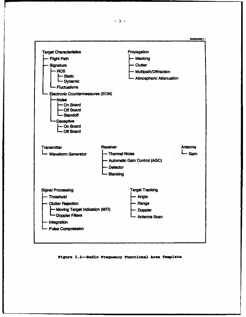
Recognizing that many aircraft susceptibility models have similar
modeling components or functional elements, the original SMART approach
started with the decomposition of a given susceptibility model into
common functional areas. Each functional area is further decomposed
into functional elements as illustrated for radio-frequency (RF) sensors
in Figure 1.1 (71; then the same functional element in all models can be
validated with a common database of test results. This approach
potentially avoids the redundant and costly testing otherwise necessary
to validate each model.
Currently, the functional element decomposition has been applied to
three models: ESAMS, ALARM, and the RADGUNS model [7,8]. Five
functional elements in ESAMS and ALARM were compared with both
scientific and technical intelligence (S&TI) data and flight test data
from the ICON GLASS exploitation effort during the SMART Proof-of-
Concept (9,10]. These comparisons served two purposes: (1) to refine
IThe SMART model set includes five models: Enhanced Surface-to-AirMissile Simulation (ESAMS), Advanced Low-Altitude Radar Model (ALARM),Radar-Directed Gun Simulation (RADGUNS), the Trajectory Analyses Program(TRAP), and the Air-to-Air System Performance Evaluation Model (AASPEM).
-3-
-UUID ~ I.f
Target Characteristics Propagation
SFlight Path - Masking
SSignature ClutterRCS - MultpattWDIlffraction
StLyatic LAtmospherlc Attenuation
SFluctuations
Electronic Countermeasures (ECM)-Noise-. On Board
-Deceptive
Transmitter Receiver AntennaL Waveform Generator - Thermal Noise L Gain
Automatic Gain Control (AGC)
DetectorBlanking
Signal Processing Target Tracking
Threshold -Angle
Clutter Rejection - Range
L Moving Target Indication (MTI DopplerDoppler Filters L Antenna Scan
Integration
Pulse Compression
Figure 1.1-Radio Frequency Functional Area Tonmlate
-4-
various generic model components by using threat-specific data from the
S&TI and (2) to identify modeling errors.
Several errors were successfully identified in both ESAMS and ALARM
during the proof-of-concept (10,11] and convincingly demonstrate the
value of the functional element decomposition and validation. Of
particular significance, two problems discovered in ALARM compensated
one another at the integrated model level. One was a moving target
indication (MTI) modeling error that resulted in an overestimation of
signal-to-noise ratios (SNR); the other was the neglect of tracking
errors that underestimated the SNR [11]. Compensating errors of this
type are extremely difficult to identify in an integrated-model approach
to validation and demonstrate that functional element validation is a
necessary first step.
On the other hand, the validation of the individual functional
elements alone is not sufficient evidence that the overall model is
validated. The basis for this assertion is that all models are only
approximations of the real world, and any neglected aspect whether
intentional or unintentional could potentially invalidate the overall
model even when all modeled functional elements are valid. Also,
validated functional elements could be improperly integrated and result
in an invalid model. Therefore, the final model output needs some
validity check.
A two-phased approach to model validation that addresses both
concerns combines the existing functional element validation with an
integrated-model validation. This approach can be based on an analogy
with weapon system test and evaluation and is described in Section 2
with an emphasis on the Phase II or integrated-model validation.
Section 3 discusses generic, model-independent Phase II validation
objectives for the general class of aircraft susceptibility models.
Section 4 focuses on specific Phase II validation objectives for ESAMS
and ALARM. Notional test plans that describe data requirements, test
procedures, and data analysis necessary to resolve the specific
validation issues for ESAMS and ALARM are presented in Appendices A and
B, respectively. Given the limited resources available for model
validation, Section 5 offers some guidance in the prioritization of

I5-
critical aualytical issues (CAIs) for ESAMS and ALARM. While a
comprehensive model validation may be unattainable, useful validation
for the majority of common model uses is not.
6-
2. * )DUL VALIDATION VPWUE
As described in the Introduction, the original SMART approach to
model validation involved model decomposition into functional elements
and the validation of individual functional elements. While this first
step is necessary, it is not sufficient; an additional step is necessary
that examines the integrated model results. In this section, we
describe a two-phased approach to model validation that preserves the
functional element validation as Phase I and adds the integrated model
validation as Phase II. The objectives and approaches of each phase are
fundamentally different and can be likened to the two phases of weapon
system test and evaluation.
WEAPOK SYITZ TET AND RVALUATION ANALOG
Before describing the two-phased approach to model validation, it
is useful to briefly examine the test and evaluation of weapon systems
within DoD (for further details see Reference (31). During the
acquisition process, weapon systems must pass two phases of test and
evaluation before full scale production is authorized. The first phase
is developmental test and evaluation; the second phase is operational
test and evaluation. Without going into excessive detail, the primary
objective of developmental testing (DT) is to demonstrate that a weapon
system meets all technical performance requirements as specified in the
Test and Evaluation Master Plan (TEMP). For aircraft weapon systems
this demonstration usually consists of bench or anechoic chamber testing
and limited flight testing in which the test article is instrumented to
record technical performance data. This testing is conducted by
technical experts and is the responsibility of the developing agency
(program manager). In addition, DT is often conducted with contractor
support since hardware or software modifications may be necessary to
meet the system specifications.
Once a weapon system has passed the technical evaluation
(TECHEVAL), it is certified ready for operational testing (OT). OT is
then conducted to demonstrate that the weapon system can meet critical
-7-
operational effectiveness and suitability requirements, which
collectively are referred to as critical operational issues (COIs).
Sufficient resources (e.g., number of missiles to test, funding for
flight hours on a test range, cr number and types of threat systems) are
rarely available to complete a comprehensive operational test. Simply
too many weapon system employment conditions exist to test them all with
statistical confidence. The COIs help provide a focus on the most
critical test conditions; however, many examples exist of weapon systems
that were successfully tested and fielded yet possessed serious
operational deficiencies. In spite of these limitations, OT provides an
essential, independent evaluation of operational capabilities by
service-representative personnel.
For modeling and simulation software, a test and evaluation or
validation procedure can be established by analogy. The "DT phase' may
be defined to consist of the functional element decomposition and the
comparison of functional element performance to test data, while the OOT
phase' may be defined to consist of an evaluation of integrated model
performance.
1UM I: VWCTYIOUAL ZLým VILIDATIOK
The objective of the functional element validation is to
demonstrate that the individual functional elements of the model
accurately represent the performance or characteristics of the
corresponding target or weapon system attributes. First and foremost,
the corresponding software modules in the model must be able to be
isolated and tested independently from the rest of the model. Since
this typically will not represent an intended use of the model, this
testing requires software engineering to isolate a particular software
module and to develop the necessary off-line drivers to test them. This
software engineering requires a code familiarity that usually only the
software developers possess; consequently, they are integral to the
functional element validation.
The next step is to compare the functional element performance or
characteristics with actual system data. For example, the validity of a
target tracking element depends on dynamic filter responses. Its
I8-
validation requires a comparison between the modeled filter resp ase to
the actual system filter response. Typically these data are available
from S&TI analyses of foreign materiel exploitation (FME) where filter
responses to standard step and ramp input signals are tested and
documented. Given the narrow focus and generally technical nature of
the functional element performance or characteristics, S&TI data and not
flight test data are the appropriate source for functional element
validation.
Appropriate measures of effectiveness (MOEs) or measures of
performance (MOPs) to compare in the functional element validation are
technical system performance parameters. These may include voltages,
powers, or signal-to-noise or signal-to-interference ratios. It is the
model developers again who will be the most knowledgeable in designing
specific comparison tests and in choosing the appropriate measures.
Pub= 1: ZNTEATU DMOELor VALXMZION
The objective of the Phase II validation is to execute the model as
originally intended by the model design and to compare the available
outputs to performance capabilities of the real system. To achieve this
objective, a number of steps will be required that can be patterned
after related steps in the operational testing of weapon systems.
The first step in this process is simply to identify a list of
model uses that need validation of model outputs. As in the case of
operational testing, it will rarely be possible to validate the model
for all possible applications. The most critical applications-namely,
those for which the model will be used most frequently or those for
which the model may be particularly sensitive--will be identified as
CAIs in analogy to the COIs of weapon system test and evaluation. For
aircraft susceptibility models, these CAIs represent issues such as the
detectability of aircraft with conventional signatures (a frequent model
usage), as well as the detectability of low-observable (LO) aircraft (a
stressing model usage requiring accurate clutter and multipath
modeling).
Weapon system COIs are usually stated as questions to be resolved
in OT (e.g., "Does the system accurately detect and identify. . . ? or
-9-
"Is the system reliable, maintainable, and available?'). Effectiveness
and suitability criteria are usually provided in the TEMP, and the
resolution of COIs is based on a comparison of test results to these
criteria. In model validation, the situation is less straightforward.
Potentially a model may be used for several diverse applications that
require different degrees of accuracy. For this reason, a specific CAI
would be worded to ask, for example, OHow accurately does the model
predict . . .a rather than 'Does the model accurately predict. . . .
The determination that a demonstrated accuracy is acceptable for a
specific application is a model accreditation decision and should be
separate from model validation.
The next step is to identify appropriate MOEs or MOPs for each CAl.
These quantities have operational and analytical significance. Example
MOEs may include radar detection range, track error, missile miss
distance, etc., not voltages, powers, or signal-to-interference ratios
as used in the Phase I validation. These MOEs provide the basis for
comparing Phase II model validation results to operational test data and
consequently determine the data that are needed.
The third step is to design and conduct the tests. Similar to
operational test and evaluation, a single test does not-have to be
designed to resolve all the critical analytical issues. Rather an
incremental approach that prioritizes CAIs for resolution may be useful.
This approach may allow the validation of certain CAIs and subsequent
model accreditation for certain limited applications, while deferring
those CAIs for which test data are unavailable or difficult to obtain
such as LO detection data or fuzing and warhead data.
Another important consideration in the design of a validation test
plan is the number of replications needed for each test condition to
ensure that any comparisons between flight test data and model results
have statistical confidence. It is often difficult to determine this
number a priori since it will depend on the variance of the replications
and the type of statistical test used and may be constrained by other
factors such as available funding or range access.
The last step is to analyze and document the results. This step
involves the evaluation of MOEs, comparisons between test data and model
- 10 -
results, and the resolution of CAIs. Unlike the situation in
operational testing of weapon systems where a minimum performance
threshold is usually provided to the test agency and must be met or
exceeded to satisfactorily resolve a COI, generally model validation
will not have threshold values. The resolution of CAIs requires a
statement of model accuracy with respect to validation data and some
estimate of the statistical confidence.
Just as the operational test and evaluation of weapon systems
requires an independent test agency to preclude the appearance of
prejudice in the testing, the Phase II validation should be conducted by
someone other than the model developers. Ideally, the Phase II
validator will have the appropriate analytical and operational expertise
in addition to model familiarity.
- 11 -
3. gIOffRZC PS I MODUDZL VALDTZON OBJrCTIVES
Aircraft survivability is defined as consisting of two major
components: susceptibility and vulnerability. Susceptibility is
defined as 'the degree to which a device, equipment, or weapon system is
open to effective attack due to one or more inherent weaknesses [3],0
while vulnerability is defined as 'characteristics of a system that
cause it to suffer definite degradation as a result of having been
subjected to a certain level of effect in an unnatural hostile
environment (3].' Aircraft susceptibility models, therefore, in general
are designed to predict the conditions under which aircraft can be
detected and effectively attacked with sensors and weapon systems of all
types. These include RF, infrared (IR), and electro-optical sensors,
anti-aircraft artillery (AAA), surface-to-air missile (SAM) systems, and
air-to-air missile (AAM) systems, for example.
Just as functional comnmonalities among different aircraft
susceptibility models allow the identification of functional areas and
functional elements in the Phase I validation, other model commonalities
allow the identification of common validation categories in the Phase II
validation. For example, the successful engagement of an aircraft can
be decomposed into (at least) four engagement phases. These phases
usually consist of target detection, followed by target tracking, weapon
launch and flyout, and finally, weapon intercept. Each engagement phase
usually has different effectiveness measures that can be examined as a
function of scenario conditions such as target flight path, signature,
countermeasures, and different natural environments (i.e., terrestrial
and atmospheric characteristics).
Using this categorization, a generic, Phase II model validation
template is presented in Table 3.1 along with important operational
MOES. The first category is target detection. This category of vali-
dation issues is common to both sensor and weapon system models, whereas
the remaining categories generally apply only to weapon system models. 1
1Target tracking is a sensor function; however, tracking is onlynecessary to guide a weapon.
- 12 -
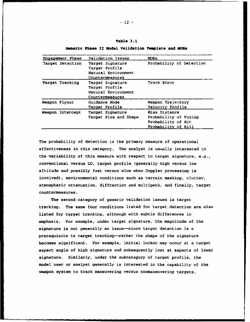
Table 3.1
Generic Phase I1 Model Validation Temlate and MDRa
Engagement Phase Validation Issues MOEsTarget Detection Target Signature Probability of Detection
Target ProfileNatural EnvironmentCountermeasures
Target Tracking Target Signature Track ErrorTarget ProfileNatural EnvironmentCountermeasures
Weapon Flyout Guidance Mode Weapon TrajectoryTarget Profile Velocity Profile
Weapon Intercept Target Signature Miss DistanceTarget Size and Shape Probability of Fuzing
Probability of HitProbability of Kill
The probability of detection is the primary measure of operational
effectiveness in this category. The analyst is usually interested in
the variability of this measure with respect to target signature, e.g.,
conventional versus LO, target profile (generally high versus low
altitude and possibly fast versus slow when Doppler processing is
involved), environmental conditions such as terrain masking, clutter,
atmospheric attenuation, diffraction and multipath, and finally, target
countermeasures.
The second category of generic validation issues is target
tracking. The same four conditions listed for target detection are also
listed for target tracking, although with subtle differences in
emphasis. For example, under target signature, the magnitude of the
signature is not generally an issue-since target detection is a
prerequisite to target tracking-rather the shape of the signature
becomes significant. For example, initial lockon may occur at a target
aspect angle of high signature and subsequently lost at aspects of lower
signature. Similarly, under the subcategory of target profile, the
model user or analyst generally is interested in the capability of the
weapon system to track maneuvering versus nonmaneuvering targets,
- 13
whereas random target maneuvers have less affect cn target detection.
In general, more varied countermeasures exist for degrading tracking
effectiveness.
Track error is the primary MOE for target tracking. Predicted
track errors plotted as a function of time or target position for
nonmaneuvering targets may provide a useful validation of modeled servo
responses in azimuth, elevation, range, and Doppler. For maneuvering
targets or targets in the presence of countermeasures, comparing time-
averaged track error distributions may be sufficient.
The third category listed in Table 3.1 is weapon flyout. Guidance
mode and target profile are two conditions identified in this category.
The guidance mode may be 'unguided' as in the case of an anti-aircraft
artillery round, or it may be one of potentially several operator-
selectable modes for complex radar-guided missiles. Target profile is
an important validation issue since some weapons are relatively slow and
nonmaneuverable and may be defeated with simple target maneuvers, even
though the target is being accuirately tracked. For both conditions the
primary MOEs of interest are the weapon trajectory and velocity profile.
The last category listed in Table 3.1 is weapon intercept. Two
validation issues in this category are target signature and target size.
Target signature is listed because weapons that use a proximity fuze to
detonate a warhead require the detection of reflected target energy.
The target signature seen by a weapon fuze at close range may be
significantly different from that seen by a ground-based tracking radar
(i.e., near- versus far-field radar cross sections).
Target size and shape are also important for determining whether a
weapon projectile (bullet or wai°,ead fragment) will impact the target.
The probability of hit depends on the presented area of the target to
the weapon projectile or fragmentation pattern. Example target classes
of different size and shape, which should be separately examined for
model validation include heavy bombers and cargo aircraft (e.g., B-52,
B-lB, C-130), fighters (e.g., F-15, F-16, F-18), and drones or missiles
(e.g., BQM-74, Tomahawk, ALCM, SCUD, JSOW).
Individual weapon intercept outcomes depend on a number of random
variables and cannot be predicted deterministically. The validation of
- 14 -
issues in this category, therefore, requires the comparison of MOE
distributions for model and test results. The four MOEs identified in
Table 3.1 are miss distance, which is defined as the closest point of
approach (CPA), the probability of fuzing that is appropriate for
weapons with a fuze-activated warhead, the probability of hit, and the
probability of kill (PK) given a hit.)
As mentioned previously, not all the validation issues are relevant
for each susceptibility model. Those that are will depend on specific
model capabilities and intended applications. Using Table 3.1 as a
generic template, model-specific validation issues (the CAIs) can be
straightforwardly developed. This process is illustrated for ESAMS and
ALARM in the next section.
2The scope of the SMART project is limited to susceptibilitymodeling; therefore, vulnerability, i.e., the conditional probability ofkill given a hit will be considered a limitation to the scope of SMARTvalidation (LIMSCOPE).
- 15 -
4. MODEL SPECIFIC PHUE II OBJECTIVES
Having briefly discussed the generic or model independent aspects
of the Phase II model validation in Section 3, this section illustrates
the development of model-specific CAIs for ESAMS and ALARM. Model-
specific CAIs will depend on intended model uses that are limited by
modeling resolution, available output quantities, and simplifying
assumptions. After discussing the general model uses and limitations,
we present a tentative list of CAIs and MOEs for both models. Some
obvious subjectivity is involved when defining CAIs since two or more
subobjectives may be combined into a single CAI to keep the overall
number of CAIs manageable.
ESAMS
The ESAMS model was developed to predict the capabilities of radar
and infrared guided SAM systems possessed by the former Soviet Union.
The original model design and development date back to the late 1970s
and are based on intelligence assessments and engineering estimates of
Soviet SAM design and performance capabilities. BDM developed and
currently maintains ESAMS under contract with the Air Force Studies and
Analyses Agency (AFSAA). The model is written in FORTRAN, and the
current version (2.6.2) consists of approximately 130,000 lines of code
(50 percent of which are comments) in about 750 subroutines. ESAMS has
been widely used in each of the services for aircraft survivability
assessments, in numerous studies including cost and operational
effectiveness analyses (COEAs), and in support of operational
evaluations.
ESAMS contains a fairly detailed level of modeling and numerous
user-selectable options. For example, the model can be run with a
smooth, flat earth and a model-defined target flight path consisting of
constant speed, heading, and altitude, or the user may model a specific
geographical location and input Defense Mapping Agency (DMA) digital
terrain elevation data and mission plan a more realistic flight path.
The target signature may optionally include the effects of glint and
- 16 -
scintillation, terrain clutter is computed for any of a dozen different
terrain types, and various options exist to model target endgame
maneuvers, electronic countermeasures (ECM), and warhead fuzing.
Radar detection in ESAMS is basically modeled at the radar rangeequation level of detail with clutter and multipath optionally included.
Target tracking is modeled via detailed range, angle, and Doppler
tracking loops with system-specific filter and servo responses. The
missile performance is modeled with equations of motion involving five
degrees-of-freedom (roll stabilized) and uses thrust, mass, and drag
data obtained from intelligence assessments or FME.
The user is responsible for defining most of the target-related
characteristics in ESAMS. These include the target signature,
vulnerability data, and ECM. Target signatures can be specified at
arbitrary resolution in elevation and azimuth. Vulnerability data
consist of blast kill radii and the location and size of aircraft
vulnerable components. The types of ECM modeled include most types of
deception generated by self-protection janmers (e.g., range and velocity
gate pull-off techniques, swept square waves, etc.), in addition to
chaff and towed decoys.
In spite of the numerous modeling options, several model
assumptions and limitations also potentially preclude the model's use in
certain applications. ESAMS is currently designed to model both the
target acquisition and target tracking functions of the SAM fire control
radar1 and missile flyout at user-defined launch times. Other equipment
normally deployed in a SAM fire unit may include additional target
acquisition radars and command and control vehicles, which are not
modeled. Typically, a target engagement sequence begins when the target
acquisition radars first detect a target or targets. This information
is then relayed to a command and control vehicle where the target tracks
are fused and correlated with other target data possibly from remote
sensors. Targets are prioritized and selected for engagement, and
1Some of the SAM systems modeled have separate (but co-located)radars for acquisition and track while other systems use a single radarwith separate acquisition and track modes.
- 17 -
target assignments are finally relayed to the fire control operators.
The fire control radar must be slewed to the correct target azimuth and
elevation angles; then the target is detected and locked-on.
An ESAMS simulation begins with the fire control radar already
boresighted on the target; as soon as the SNR is sufficient to acquire
and lock-on, a missile may be launched. This assumption, referred to as
"Nperfect cueing," precludes the analysis of the various hand-off delays.
Another model limitation is related to the assumption of perfect
cueing. ESAMS has only a limited capability to model target
reacquisition following a break-lock in tracking. If sufficient angle
or range errors are induced into the tracking loops (e.g., by clutter or
deceptive electronic countermeasures [DECM]) to cause a loss of
tracking, no capability exists to reacquire the target. If the break-
lock occurs in the Doppler tracking loop of a missile seeker, however,
reacquisition of the target Doppler frequency is modeled according to
known or assessed capabilities of the specific seekers.
Other model limitations include the lack of standoff noise or
deception jammers, e.g., the EF-iI1A or EA-6B, no man-in-the-loop (MITL)
modeling, and the restriction to single target engagements. 2 Mission
planning against SAM defenses normally includes standoff jammer support.
Neglecting this support in the simulation restricts potential
applications. The omission of MITL modeling precludes the analysis of
important electronic counter-countermeasures (ECCM), such as manual
tracking and mode switching, that further limits the model
applicability. The restriction to single-target engagements, while
adequate for many older Soviet SAM systems, does not accurately
represent several of the more modern, phased-array systems with multi-
target engagement capability. ESAMS does not provide an accurate
representation of SAM effectiveness in any of these situations.
In applications for which the model limitations are acceptable, the
single, most frequently used ESAMS output is the PK. For a given target
signature, vulnerability, and flight path, the SAM engagement or PK
envelope can be predicted. These engagement envelopes are frequently
2Many of the SAM systems modeled in ESAMS have multitargetengagement capabilities, but this capability is not modeled.
- 18 -
used as inputs to more highly aggregated models such as mission-level or
campaign models or are used in relative comparisons for targets with
different signature characteristics, electronic countermeasures, etc.
While the PK is probably the most frequently used model output, it
is beyond the scope of the SMART validation effort. As described in
Section 3, four phases are characteristic of a SAM engagement, and ESAMS
outputs other useful information associated with each of these phases.
For example, in the target detection phase, ESAMS can be used to predict
target acquisition and lockon ranges as a function of target signature,
profile, and environmental conditions. In the target tracking phase,
mean track errors and cumulative distributions have been used to assess
the effectiveness of different countermeasures. Missile fly-out
modeling determines the kinematic engagement envelope (footprint) for a
SAM system, and ESAMS-predicted missile trajectory or velocity profiles
are frequent inputs to higher-level models such as mission-level or
campaign-level models. Finally, in the weapon intercept phase, missile
miss distances and probabilities of kill are frequently used to assess
different target signatures, vulnerabilities, and endgame
countermeasures. For a comprehensive model validation, all the
available model outputs must be validated in each engagement phase.
Critical Analytical Issues
This subsection develops the CAIs for ESAMS validation based upon
available model outputs and potentially stressing applications
associated with each of the four weapon engagement phases described
generically in Section 3.
Target Detection. Given that the ESAMS assumptions of perfect
cueing and neglect of standoff ECM are acceptable for a particular
analysis, target detection is the first phase in a SAM engagement. Most
aircraft currently fielded have relatively large RF and IR cross
sections (,conventional' signatures). For many ESAMS applications, the
validation of detection ranges for aircraft with conventional signatures
is sufficient. Other aircraft such as the F-117, B-2, and F-22 and some
cruise missiles have LO signatures. LO signatures present a
particularly stressing case for radar detection modeling since the
-19 -
detection of LO aircraft (particularly at low altitude) requires that RF
propagation and terrain clutter be accurately modeled. For this reason
and the additional difficulty of gaining access to test data for
validation involving LO aircraft, two separate target detection CAIs are
proposed for each SAM sensor modeled: 3
How accurateiy does the ESAMS SA-X model predict target
detection ranges for targets with conventional signatures in
the absenc• of electronic countermeasures?
How accurately does the ESAMS SA-X model predict target
detection ranges for targets with LO signatures in the absence
of electronic countermeasures?
Target Tracking. Once ESAMS has predicted that the target SNR is
adequate for detection, the model transitions to the track mode and
determines whether the SNR and SAM tracking response is adequate to lock
on to and track the target. Target tracking is not only sensitive to
the SNR but depends significantly on target maneuvers and DECM intended
to induce range, angle, or Doppler errors into the tracking loops.
Given the relatively large number of potential countermeasures that can
be modeled in ESAMS, the best validation approach is to focus on the
more benign conditions first, i.e., nonmaneuvering and maneuvering
targets with no ECM first then subsequently extend the validation to
include ECM focusing on a particular category of ECM separately (e.g.,
chaff, DECM. towed decoys, etc.).
Target tracking in some SAM systems is further complicated by the
missile guidance mode. Many SAM systems employ command-guidance, which
only requires target tracking by the fire control radar. Other SAM
systems, however, employ a guidance mode referred to as semiactive
homing in which the fire control radar tracks and illuminates the target
with continuous wave (CW) RF energy; a seeker located on the missile
also tracks the target via the reflected energy. For these semiactive
3The most general case has three sensors: the acquisition radar(or acquisition mode of a multifunction radar), the track radar, and amissile seeker.
- 20 -
homing systems, both the ground-based radar and missile-seeker tracking
must be validated.
Based on the preceding discussion, nine target tracking CAIs are
proposed:
How accurately does the ESAMS SA-X model predict target
tracking errors for nonmaneuvering targets in the absence of
electronic countermeasures?
" How accurately does the ESAMS SA-X model predict target
tracking errors for maneuvering targets in the absence of
electronic countermeasures?
" How accurately does the ESAMS SA-X model predict target
tracking errors for nonmaneuvering and maneuvering targets in
the presence of electronic countermeasures consisting of chaff?
" How accurately does the ESAMS SA-X model predict target
tracking errors for nonmaneuvering and maneuvering targets in
the presence of electronic countermeasures consisting of DECM?
" How accurately does the ESAMS SA-X model predict target
tracking errors for nonmaneuvering and maneuvering targets in
the presence of electronic countermeasures consisting of a
towed decoy?
" How accurately does the ESAMS SA-X model predict target
tracking errors for nonmaneuvering and maneuvering targets in
the presence of electronic countermeasures consisting of
terrain bounce jamming?
" How accurately does the ESAMS SA-X model predict missile-seeker
tracking for semiactive homing missiles against nonmaneuvering
targets in the absence of electronic countermeasures?
" How accurately does the ESAMS SA-X model predict missile-seeker
tracking for semiactive homing missiles against maneuvering
targets in the absence of electronic countermeasures?
" How accurately does the ESAMS SA-X model predict missile-seeker
tracking for semiactive homing missiles against nonmaneuvering
and maneuvering targets in the presence of electronic
- 21 -
countermeasures including chaff, DECM, towed decoys, and
terrain bounce jamming?
Missile Flyout. Once a SAM system locks on to a target and
launches a missile, tracking errors are computed and fed into a guidance
computer (or auto-pilot in semiactive systems), and missile control
surface corrections are computed to guide the missile to target
intercept. Most of the engagement conditions that affect target
tracking will also affect missile flyout (i.e., target maneuvers and
countermeasures) but for simplicity are categorized into three CAIs for
validation:
How accurately does the ESAMS SA-X model predict missile fly-
out trajectories and times of flight for nonmaneuvering targets
in the absence of target countermeasures?
How accurately does the ESAMS SA-X model predict missile fly-
out trajectories and times of flight for maneuvering targets in
the absence of target countermeasures?
0 How accurately does the ESAMS SA-X model predict missile fly-
out trajectories and times of flight for nonmaneuvering and
maneuvering targets in the presence of target countermeasures
including chaff, towed decoys, on-board self-protection
jamming, or terrain bounce jamming?
Missile Intercept. The final phase of a SAM engagement is missile
intercept or the endgame. The missile must be guided sufficiently close
to the target so that the fuze will detect the target and detonate the
warhead. The distance and target-missile orientation also determine
warhead blast and fragment damage; therefore, accurate predictions of
missile miss distance and the probability of fuzing are important model
outputs.
At warhead detonation, ESAMS computes warhead blast and fragment
damage based on user-defined blast radii and vulnerable components for
the target of interest. As previously mentioned, the scope of the SMART
validation precludes a vulnerability validation; therefore, the ESAMS
- 22
computed PK will not be validated. The PK, however, can be written as
the product of a conditional probability of kill given a hit times the
probability of hit. By definition, the probability of hit is part of
the target susceptibility and technically within the scope of the SMART
validation.
The validation of the ESAMS-predicted probability of hit requires
destructive testing, which is usually a LIMSCOPE in OT. The expense of
shooting down a tactical aircraft, particularly an LO aircraft, will
preclude the complete validation of this model output. Some data may be
obtainable for target drones or cruise missiles used in live-fire tests.
We propose three missile intercept CAIs for ESAMS validation:
" How accurately does the ESAMS SA-X model predict missile miss
distance and endgame geometry distributions at the time of CPA?
" How accurately does the ESAMS SA-X model predict the
probability of missile fuzing?
" How accurately does the ESAMS SA-X model predict the
probability of hit given missile fuzing?
1aauremoa of Xffoativmoss
Target detection and lock-on range are the appropriate MOEs for
validating the ESAMS target acquisition CAIs. To adequately test the
target acquisition CAIs, model predictions must be compared with test
data for multiple nonmaneuvering profiles both radially toward the SAM
radar and at fixed offsets from the radar, for several different
aircraft types with conventional and LO signatures, and at several
different altitudes.
Track error is the primary MOE for validating ESAMS target tracking
predictions. This error occurs between the radar or missile seeker
boresight and the actual target position. Modeled and actual track
errors can be compared as either time series in azimuth, elevation, and
range or as statistical distributions (for stationary time series). It
is important not only that ESAMS accurately predicts track errors when
the SAM radar is tracking but also that break-lock occurrences (caused
by terrain masking, clutter, or ECM) are modeled accurately. As
- 23 -
mentioned previously, ESAMS does not model target reacquistion after a
break-lock in tracking (except for Doppler reacquisition in missile
seekers); therefore, some of the generic MOEs proposed in Section 3,
such as the probability of track, mean track duration, and mean
reacquisition time, are irrelevant except for missile-seeker modeling.
Modeled and measured missile fly-out trajectories are most easily
contrasted by comparing times-of-flights and plots of x,y, and z
position as a function of time or as a function of ground distance from
the launch site. Often visual inspection is sufficient to estimate the
accuracy; however, quantitative measures such as the root mean square
(RMS) error or the correlation coefficient are also useful as single-
valued quantitative measures.
Appropriate MOEs for missile intercept or endgame validation
include missile miss distance, the probability of fuzing, the
probability of hit given fuzing, and the probability of kill given a
hit. Missile miss distance is defined as the point of closest approach
to the target. The probability of fuzing is defined as the number of
intercepts in which missile fuzing occurs divided by the total number of
missile intercepts tested.
Undoubtedly, the PK is the single, most frequently used ESAMS
output; however, as stated earlier, the PK includes a vulnerability
component and is currently beyond the scope of the SMART validation.
The probability of hit is a susceptibility measure, but its validation
requires destructive testing, which generally is also a LI1SCOPE to
operational testing.
Missile intercept MOEs are sensitive to random tracking and
guidance errors, endgame target maneuvers, and ECM; therefore, single
intercept comparisons are not sufficient. It is necessary to
characterize the distribution of missile intercept MOEs such as missile
miss distance and to compare the distribution means and standard
deviations from testing and model prediction. The expense of testing a
statistically significant number of telemetered threat missiles against
target drones will generally preclude complete resolution of the endgame
CAIs.
- 24 -
Notional test plans developed from the ESAMS CAIs and HOEs listed
in this section are described in Appendix A. Each test consists of
three sections: (1) the statement of objective that is based on a
specific CAI, (2) the test procedure that identifies important test
conditions, target profiles, and test data, and (3) the data analysis.
ALA=
ALARM is a generic radar detection model that can be used to
compute the probability of target detection for potentially all types of
land- or sea-based radars. Like ESAMS, ALARM is a government-owned
model and is widely used in aircraft survivability assessments. ALARM
was developed and is currently maintained by Science Applications
International Corporation (SAIC) under contract with the Air Force
Wright Laboratories (AF/WL). The model is written in FORTRAN, and the
current version (ALARM 91) ccs'sts of approximately 23,000 lines of
code (40 percent comments) in about 100 subroutines.
Radar detection in ALARM is basically modeled at the radar range
equation level of detail with separate algorithms for low or medium
pulse repetition frequency (PRF) radars with moving target indication
(MTI) and pulsed Doppler or CW radars. Like ESAMS, several user-
selectable options are available to enhance the modeling realism. For
example, ALARM can be executed in either a featureless terrain mode
(round, smooth earth) or in a site-specific mode that uses DMA digital
terrain elevation data to compute terrain masking, multipath, and
diffraction. Other options include the capability to model one or more
standoff noise jammers (e.g., EF-i1IA or EA-6B) and the radar cross
section (RCS) enhancement from rotor blades on rotary-wing aircraft.
Also like ESAMS, ALARM incorporates certain modeling assumptions
and limitations that potentially preclude its use in certain
applications. For example, ALARM is not a time-based simulation and
does not model antenna scan. The antenna is always pointed in azimuth
toward the true target location, and no scan-to-scan correlation
information is used to compute the probability of detection. In
reality, the assertion is that an experienced radar operator can use
scan-to-scan signal correlation (i.e., M hits out of N scans) to improve
- 25 -
the probability of detection. The neglect of antenna scan also
introduces errors in predicted detection ranges for *pop-upo targets,
i.e., targets that become unmasked during a scan period when the antenna
beam is at a different azimuth angle.
Another ALARM limitation is the antenna pattern representation.
The model user defines antenna patterns by entering the gain at a fixed
angular resolution along one cut in azimuth (elevation angle constant)
and one cut in elevation (constant azimuth). The full three-dimensional
pattern is then constructed by means of linear interpolation in azimuth
and elevation. This assumption introduces errors for multi-beam radars
and for antenna sidelobe characterization that could invalidate model
use in applications involving sidelobe jamming or in applications
requiring accurate clutter prediction (i.e., for LO targets).
For user-specified radar and antenna characterization data and
aircraft signature and location data, ALARM computes basically three
output quantities: the detected target power, clutter power, and the
signal-to-interference ratio. The model will also indicate whether the
target is masked or unmasked by terrain, and if unmasked whether it is
detected or not based on the user-specified target fluctuation
statistics and desired probabilities of detection and false alarm.
ALARM validation, therefore, requires a comparison of model-predicted
probabilities of detection to actual flight test data.
One complication that arises for ALARM validation is the lack of
standard radar and antenna input data. The developers of ALARM assumed
each model user would provide the radar and antenna data necessary to
characterize the system they wished to model. Analysts typically
consult available intelligence sources for data; however, the available
multiple sources are not always consistent, which can lead to different
performance predictions. This problem will be avoided within the SMART
project by using data sets developed from measured hardware data. The
ALARM radar and antenna data extracted from S&TI data and used for the
functional element validation will be considered part of the "modell and
used in the Phase II validation.
- 26
Critical Analytical issues
Since ALARM is only a sensor model and not a weapon system model
like ESAMS, only the first category of validation issues in Table 3.1 is
relevant. Similar to ESAMS applications, the majority of ALARM
applications will involve aircraft with conventional signatures. For
this reason and the fact that LO signatures will critically stress the
accuracy of signal propagation and clutter modeling, separate CAIs are
proposed for targets with conventional and LO signatures. Also since
different algorithms are used to model low and medium PRF radars versus
pulsed Doppler or CW radars, these two radar classes must be validated
separately by representative systems. 4
The ALARM option of predicting target probabilities of detection in
the presence of standoff noise jamming is a sufficiently critical
application to require separate validation; therefore, a separate CAI is
proposed. In addition, the extensive spherical earth knife-edge (SEKE)
diffraction code integrated into ALARM 91 requires separate validation. 5
Based on these model considerations, we propose the following six
CAIs:
How accurately does the ALARM model predict the probability of
target detection for pulsed radars against targets with
conventional radar cross sections in the absence of standoff
noise jamming?
" How accurately does the ALARM model predict the probability of
target detection for pulsed radars against targets with LO
radar cross sections in the absence of standoff noise jamming?
" How accurately does the ALARM model predict the probability of
target detection for pulse Doppler or CW radars against targets
4While the ALARM 'code' can be validated generically by validatingthe model outputs for several representative systems, the ALARM 'model'must encompass the threat-specific input data and requires validation ona system-by-system basis using comparisons to actual test data.
5Purportedly this code has been validated by MIT LincolnLaboratories; however, its integration into ALARM requires separatevalidation. Knife-edge diffraction is particulary important for low-frequency RF propagation, e.g., associated with very high frequency(VHF) radars.
- 27 -
with conventional RCSs in the absence of standoff noise
jamming?
How accurately does the ALARM model predict the probability of
target detection for pulse Doppler or CW radars against targets
with LO radar cross sections in the absence of standoff noise
jamming?
How accurately does the ALARM model predict the probability of
target detection for pulsed and pulse Doppler radars in the
presence of standoff noise jamming?
How accurately does the ALARM model predict terrain masking and
diffraction?
Xeaasuzes of Uffoctivonmes
As previously mentioned in Section 2, operational MOEs are
appropriate for the Phase II validation. ALARM computes and outputs
target signal powers, clutter powers, and signal-to-interference ratios
as a function of input target cross section and profile and indicates
whether the target is masked, unmasked (but not detected), or detected.
Only this last output (i.e., the specification of target detection as a
function of range) is operationally measurable without special
instrumentation and is the primary MOE for the ALARM Phase II
validation.
Initial detection range is an important analytical MOE buL not the
only one. The accurate prediction of terrain masking, clutter or ECM
masking, and antenna nulls must also be validated. This can be done
using the probability of correct correlation, which is simply defined as
the ratio of correctly predicted detection opportunities or detection
intervals divided by the total number of detection opportunities or
detection interval.
Notional test plans for Phase II ALARM validation based on the CAIs
and MOEs in this section are described in Appendix B.
- 28 -
5. VALXIDATION PRIORITIES
One objective of this report is to identify a reasonably
comprehensive set of validation requirements for Phase II or integrated
model validation for the set of models being considered in the SMART
project. As described generically in Section 3, these requirements can
be categorized by the different engagement phases modeled with different
requirements characteristic to each phase. Specific requirements are
developed for ESAMS and ALARM based on model uses in Section 4 and are
referred to as CAIs. These CAIs are stated as questions of the form:
"How accurately does the model predict. . .' The validation approach
advocated by the SMART project consists of resolving these CAIs by
comparing the model outputs to laboratory and field test data from the
actual hardware being modeled.
In general, extensive field testing probably will not be conducted
exclusively to support model validation. Field testing is expensive but
essential for other purposes such as training, test, and evaluation of
weapon systems. S&TI centers also field test exploited threat systems
to characterize performance capabilities. Data collection is typically
not a high priority during training exercises; however, operational test
and evaluation and S&TI tests are both potentially useful sources of
data for model validation and may be leveraged by additional resources
when necessary.
Typically, the lack of available field test data for certain CAIs
or small sample sizes for others will preclude a comprehensive model
validation. Simply too many combinations of threat types, target types,
flight profiles, environmental conditions, and countermeasures exist to
test them all with statistical confidence. On the other hand, a
comprehensive model validation does not have to be completed before a
model can be validly used for specific applications. One benefit of the
CAI approach is that by decomposing the overall model validation into
multiple, independent objectives, these individual objectives (i.e.,
CAIs) may be validated sequentially on a priority basis. Once a
- 29 -
particular CAI has been validated, the model can be accredited for that
specific application.
How should the CAIs be prioritized for validation? This
consideration is important since once a prioritization has been
established, it determines how to allocate available resources. Initial
model validation should prioritize the CAIs based on the most common
model applications, but subsequent prioritization may be driven by
specific model applications. For example, an F-22 study might require
the validation of LO detection modeling, whereas a study involving the
F-15E TEWS might require electronic countermeasure validation. As a
general rule, the more benign or less stressing CAIs should be validated
before more stressing CAIs. It does not make sense to validate target
tracking in the presence of countermeasures before validating target
tracking without countermeasures because if the latter is invalid, the
former is probably invalid also.
Based on the common uses of ESAMS and ALARM, what validation
priorities can be recommended?
ESAMS
The most basic use of ESAMS is the computation of PK envelopes for
RF SAMs. For aircraft with conventional RCS (5 to 10 dB or greater) in
the absence of countermeasures, the PK envelope will be determined
either by the kinematic range of the missile for targets at medium to
high altitude or by the radar horizon for targets at low altitude and by
the vulnerability of the target aircraft. The validity of the missile
flyout and endgame modeling are most important for these applications.
Moreover, for applications that require only the PK envelope, the
specific missile trajectory is not critical-only the maximum range,
altitude, and, to a lesser extent, the weapon speed (that determines the
intercept point) are the only missile fly-out quantities that need to be
validated. These quantities are largely determined by the propulsion
and aerodynamic characteristics of the missile and are insensitive to
target type.
The primary weapon intercept or endgame CAIs that are important for
aircraft with conventional RCS are the probability of fuzing and the PK
- 30 -
given fuzing. Both the probability of fuzing and the PK given fuzing
are aircraft-specific and depend on the missile-aircraft endgame
geometry. The validation of the probability of fuzing requires the
comparison of model results to a relatively large number of missile
encounters at various miss distances and endgame geometries. This
amount of data will not be available from telemetered live firings and
will require laboratory testing. The PK given fuzing depends on the
vulnerability to blast and warhead fragments, the endgame encounter
geometry, and the kill category required ('KKR, `K°, "AO, etc.). In
ESAMS, aircraft vulnerability is defined by input data that have to be
separately validated.
For aircraft with reduced or LO RCS, target detection and tracking
CAIs have a greater impact on the size and shape of the PK envelope.
Radar detection in ESAMS is based on the radar range equation. This
equation has been independently validated by extensive empirical data
and does not require revalidation in ESAMS for free-space detection
(i.e., detection at medium to high altitude where terrain clutter is not
significant). The resolution of free-space target detection CAIs then
only requires that the variables in the radar range equation such as
power, wavelength, antenna gain, target cross section, etc., be
validated. For low-altitude targets, terrain clutter and multipath
propagation are important. Computational methodologies for predicting
clutter and multipath and clutter rejection in the radar receiver have
not been independently validated to the extent of the radar range
equation and, therefore, require explicit validation in ESAMS.
Another set of important ESAMS applications is the prediction of
electronic countermeasures on SAM effectiveness, and the largest class
of countermeasures is probably DECM. DECM techniques are generally
designed to disrupt the target tracking radar or missile seeker;
therefore, the validation of ESAMS for these applications requires the
validation of target tracking CAIs both without (dry) and with DECM
(wet). Both the track error dispersion and error response to changes in
range and angle rates (dry and wet) are critical for modeling DECM
effectiveness and should be validated after missile flyout, endgame, and
detection CAIs.
- 31 -
The set of CAIs just discussed is summarized in priority order
below:
1. Missile Flyout-nonmaneuvering; no ECM
2. Missile Intercept-probability of hit
3. Target Detection--conventional signatures
4. Target Detection-LO signatures
5. Target Tracking-nonmaneuvering targets; no ECM
6. Target Tracking-nonmaneuvering targets; DECM.
This initial list covers a majority of ESAMS applications. The
other CAIs defined in Section 4 can be addressed as needed to support
specific model applications.
ALAMThe scope of validation for ALARM is much narrower than ESAMS and
focuses only on radar detection. The majority of ALARM applications
deal with detection of both conventional and LO target signatures in the
absence of countermeasures. For this reason, the CAIs for pulsed and
pulse Doppler detection of conventional targets with no countermeasures
are recommended with the highest priority, followed by the CAIs for
pulsed and pulse Doppler detection of LO targets with no counter-
measures. These CAIs are followed with lower priority by detection in
the presence of standoff noise jamming and by the CAI for terrain
masking and diffraction. This order is summarized below:
1. Target Detection--pulsed radars; conventional signatures
2. Target Detection-pulse-Doppler radars; conventional signatures
3. Target Detection-pulsed radars; LO signatures
4. Target Detection--pulse-Doppler radars; LO signatures
5. Target Detection-standoff jamming
6. Target Detection-terrain masking and diffraction.
Similar to ESAMS, the probability of detection for free-space detection
in ALARM is based on the radar range equation. Aircraft with
~ 32 -
conventional signatures require primarily the validation of input data.
For low-altitude aircraft, particularly aircraft with LO signatures,
terrain e- 'ter and multipath require explicit validation. The
predic of detection ranges in the presence of standoff jamming and
the prediction of terrain masking or knife-edge diffraction are less
common ALARM applications and are consequently prioritized below the
other CAIs.
- 33 -
A. ]SAWS TSBTY MBCRXP'ION
T8 3MBAK- 1: TARGM D3TUCTXON--CONMVNZONAL BZ0GAT=ZB
Objective
The objective of this test is to determine how accurately the ESAMS
SA-X model predicts target detection ranges for targets with
conventional signatures in the absence of electronic countermeasures.
Procedure
Flight testing will be conducted with both fixed and rotary wing
aircraft having conventional signatures. The target aircraft will fly
straight and level profiles starting beyond the maximum detection range
of the test system and will ingress at a constant heading. The target
will maintain this nonmaneuvering profile flying past the test system
and egressing until beyond maximum detection range. Multiple runs will
be flown with each of several different target types at several
different altitudes (e.g., 200, 1500, and 20,000 feet) and with initial
points and headings chosen to examine several different cross-range
offsets. Low altitude profiles will be flown at a constant above
ground-level (AGL) altitude and will be chosen to provide intervals of
terrain masking. The high altitude profiles will be flown at a constant
mean sea-level (MSL) altitude.
Test data required include time-space-position information (TSPI)
for all target profiles, blip-to-scan time histories for the acquisition
radar from which the initial detection range, mask ranges or lose detect
ranges, MTI blind speeds, Doppler notches, etc., will be extracted.
Additional data items required include the effective radiated power of
the radar, a clutter map of the site, dynamic target RCS measurements or
target RCS estimation using calibration spheres, and latitude,
longitude, and altitude of the test system to reference terrain features
of the test facility to DMA digital terrain elevation data.
Data Analysis
The target RCS, TSPI data, and terrain elevation and clutter data
will be used as inputs to the ESAMS model. Target detection as a
- 34 -
function of range will be computed with the model for the acquisition
radar and compared with the flight test results. Statistical analyses
(e.g., t-test, Wilcoxon, Kolmogorov-Smirnov, etc.) will determine the
accuracy of mean detection ranges by target type averaged over all
profiles.
Target detections computed with the model will also be compared to
test data to correlate segments of flight profiles in which detection
was lost because of clutter, terrain masking, MTI blind speeds, Doppler
notches, etc. These comparisons will be presented graphically as a
function of mission time or range from the radar and will be summarized
by the probability of correct correlation defined as the ratio of
correctly predicted scans (or scan intervals) divided by the total
number of scans (or profile time).
TYST 3R3111-2: TARGET XDTZY -- LO 83M1TYRl
Objective
The objective of this test is to determine how accurately the ESAMS
SA-X model predicts target detection ranges for targets with LO
signatures in the absence of ECMs.
?roxeft a
This test will be conducted with the same procedure used in Test
ESAMS-1 with available LO targets.
Data Analysis
Data analysis will be identical to Test ESAMS-I.
TYS! T33B11-3: TARCIT TWUNG-HOUIVUVUIM AYERGFTS
Objectivo
The objective of this test is to determine how accurately the ESAMS
SA-X model predicts target tracking errors for nonmaneuvering targets in
the absence of ECMs.
ProceQure
This test will be conducted in conjunction with Test ESAMS-I.
After initial target detection, the target will be handed off to the
track radar and tracked throughout the remainder of the profile. If a
- 35 -
break-lock occurs after the initial lockon, range reference radars may
be used to reposition the radar boresight and facilitate reacquisition.
In addition to the data items specified in Test ESAMS-l-namely dynamic
target RCS or calibration spheres, TSPI, and a site clutter map-Test
ESAMS-2 requires target azimuth, elevation, and range measured by the
test radar and the computed track errors in azimuth, elevation, and
range measured with respect to the reference radar as a function of
mission time.
Data Analysis
Target RCS, TSPI data, and terrain elevation and clutter will be
used as inputs to the ESAMS model. Predicted track errors in azimuth,
elevation, and range will be computed and compared with the flight test
data. Graphical plots and time series analyses will be used to analyze
the accuracy and dispersion of the predicted ESAMS tracking errors.
TZRT KMUKS-4: TARGET TRXCX0---K MINTAPNTRGNT8
Objective
The objective of this test is to determine how accurately the ESAMS
SA-X model predicts target tracking errors for maneuvering targets in
the absence of electronic countermeasures.
Proced=e
The procedure for this test is similar to that for Test ESAMS-3,
except that target profiles will involve a two-dimensional, 3g weave.
Data Analysis
The data analysis for this test is identical to Test ESAMS-3.
TZBYT /J•M-5: TAROZT TY CK-INO--Cl (CHAFF)
Objective
The objective of this test is to determine how accurately the ESAMS
SA-X model predicts target tracking errors for nonmaneuvering and
maneuvering targets in the presence of electronic countermeasures
consisting of chaff.
- 36 -
Procedure
This test requires target tracking data similar to that identified
in Tests ESAMS-3 and ESAMS-4 and may be conducted in conjunction with
those tests by including the manual deployment of chaff on some target
passes. In addition to the data specified in Tests ESAMS-3 and ESAMS-4,
this test requires the ejection time of each chaff bundle.
Data Analysis
Target RCS, TSPI data, terrain elevation and clutter, and chaff
deployment times will be used as inputs to the ESAMS model. Predicted
track errors in azimuth, elevation, and range will be computed and
compared with the flight test data. Graphical plots and time series
analyses will be used to analyze the accuracy and dispersion of the
predicted ESAMS tracking errors. The number of target break-locks and
reacquisition times will also be compared.
TYS" SAaWM-6: TARO=TT 'C"XNO- 3C (DC)
abjectly.
The objective of this test is to determine how accurately the ESAMS
SA-X model predicts target tracking errors for nonmaneuvering and
maneuvering targets in the presence of ECMs consisting of DECM.
Procedure
This test will require target tracking data similar to that
identified in Tests ESAMS-3 and ESAMS-4 and may be conducted in
conjunction with those tests by including DECM on some of the target
passes. In addition to the data specified in Tests ESAMS-3 and ESAMS-4,
this test requires jamner characterization data including power and
antenna gain, jammer on/off times, and the transmitted waveform
description.
Data Analysis
Target RCS, TSPI data, terrain elevation and clutter, and jammer
characterization and waveform data will be used as inputs to the ESAMS
model. Predicted track errors in azimuth, elevation, and range will be
computed and compared with the flight test data. Graphical plots and
- 37 -
time series analyses will be used to analyze the accuracy and dispersion
of the predicted ESAMS tracking errors. The number of target break-
locks and reacquisition times will also be compared.
TZUB? 3A3S-7: TARGET T'R'KING---M (TOWD DECOY)
Objective
The objective of this test is to determine how accurately the ESAMS
SA-X model predicts target tracking errors for nonmaneuvering and
maneuvering targets in the presence of ECMs consisting of a towed decoy.
Procedure
This test will require target tracking data similar to that
identified in Tests ESAMS-3 and ESAMS-4 and may be conducted in
conjunction with those tests by deploying a towed decoy on some target
passes. In addition to the data specified in Tests ESAMS-3 and ESAMS-4,
this test requires the towed decoy deployment time, deployment rate,
decoy orientation (distance and angle) with respect to the aircraft,
decoy characterization data including power and antenna gain pattern,
jammer on/off times, and the decoy waveform description.
Data Anualyals
Target RCS, TSPI data, terrain elevation and clutter, and decoy
deployment time, characterization, and waveform data will be used as
inputs to the ESAMS model. Predicted track errors in azimuth,
elevation, and range will be computed and compared with the flight test
data. Graphical plots and time series analyses will be used to analyze
the accuracy and dispersion of the predicted ESAMS tracking errors.
TEO?3•SAS-8: TARGET TRACKXNG-ECK (TET)
Objective
The objective of this test is to determine how accurately the ESAMS
SA-X model predicts target tracking errors for nonmaneuvering and
maneuvering targets in the presence of ECMs consisting of terrain bounce
jamming (TBJ).
- 38 -
Procedure
This test will require target tracking data similar to that
identified in Tests ESAMS-3 and ESAMS-4 and may be conducted in
conjunction with those tests by deploying TBJ on some of the low-
altitude target passes. In addition to the data specified in Tests
ESAMS-3 and ESAMS-4, this test requires jammer characterization data
including power and antenna gain pattern, jammer on/off times, and the
waveform description.
Data Analysis
Target RCS, TSPI data, terrain elevation and clutter, and terrain
bounce jammer characterization and waveform data will be used as inputs
to the ESAMS model. Predicted track errors in azimuth, elevation, and
range will be computid and compared with the flight test data.
Graphical plots and time series analyses will be used to analyze the
accuracy and dispersion of the predicted ESAMS tracking errors. The
number of target break-locks and reacquisition times will also be
compared.
YZST U8AS-9: MISSILZ SEM R TARGETS
Objective
The objective of this test is to determine how accurately the ESAMS
SA-X model predicts missile seeker tracking for semiactive homing
missiles against nonmaneuvering targets in the absence of electronic
countermeasures.
Procedure
The primary source of data for this test will be captive-carried
missile seekers. A second source of data will be telemetered live
missile firings when available. The target aircraft will fly straight
and level profiles radially toward the ground-based target tracking
radar and at various offsets. Target passes will consist of multiple
low-, medium-, and high-altitude profiles at several different
airspeeds. The airborne seeker testbed will fly simulated missileprofiles against the target at several different ranges. The ground-based, target-tracking and target-illumination radars must be
- 39 -
transmitting and tracking the target. Test data required include target
and airborne testbed TSPI, target signature, effective radiated power of
the target illuminator at the missile seeker, missile seeker tracking
errors, and seeker clutter.
Data Analysis
The target and airborne seeker testbed TSPI, target RCS, and
terrain elevation and clutter will be used as inputs to the ESAMS model.
The model will be run with the user-defined missile flight path option
using the airborne seeker testbed TSPI. Predicted seeker track errors
in azimuth and elevation will be computed and compared with the flight
test data. Graphical plots and time series analyses will be used to
analyze the accuracy and dispersion of the predicted ESAMS seeker
tracking errors.
T BTRBAMS-10bs MISSILE 5R TRACKIN-- AXmVRRIMTARGETS
ObJective
The objective of this test is to determine how accurately the ESAMS
SA-X model predicts missile seeker tracking for semiactive homing
missiles against maneuvering targets in the absence of ECMs.
Procedure
The procedure for this test is similar to that for Test ESAMS-9,
except that target profiles will involve a two-dimensional, 3g weave.
Data Analysis
The data analysis for this test is identical to Test ESAMS-9.
TEST RAMSB-11: MISSILE SE TRACKMIG--CK
ObJective
The objective of this test is to determine how accurately the ESAMS
SA-X model predicts missile seeker tracking for semiactive homing
missiles against nonmaneuvering and maneuvering targets in the presence
of electronic countermeasures including chaff, DECM, towed decoys, and
terrain bounce jamming.
- 40 -
Pzocedure
This test requires seeker tracking data similar to that identified
for Tests ESAMS-9 and -10. This test may be conducted in conjunction
with those tests by including ECM on some target passes. ECM
characterization data similar to those identified in Tests ESAMS-5-8 are
required.
Data Analysis
The data analysis for this test is similar to Test ESAMS-9. In
addition to seeker tracking errors, the number of target break-locks
caused by ECM and seeker reacquisition times will also be computed.
TZT IBAMS-12: MISSILBFLYO TARCGTS
Objective
The objective of this test is to determine how accurately the ESAMS
SA-X model predicts missile flyout trajectories and times-of-flight for
nonmaneuvering targets in the absence of electronic countermeasures.
Procedure
The procedure for this test requires telemetered live missile
firings of the SA-X system against target drones. Target profiles will
be straight and level flybys with altitudes and airspeeds chosen to
exercise all guidance modes of the system, except those guidance modes
used exclusively in the presence of ECM.
The data required for this test include target signature and TSPI,
atmospheric data (winds, air density, and temperature as a function of
altitude), system latitude and longitude, site clutter map, time of
missile launch, time of flight to missile intercept or CPA, and missile
position, velocity vectors (Cartesian coordinates), and orientation
(roll, yaw, pitch) as a function of fly-out time.
Data Analysis
The target TSPI, terrain elevation and clutter, and wind data will
be used as inputs to the ESAMS model. If the atmospheric density
profile is significantly different from the standard atmosphere used in
the simulation, these data will also be used via a lookup table. The
- 41 -
model will be executed with missile launch times and guidance modes
corresponding to those in the tests and the resulting missile
trajectories computed. The observed and computed trajectories will be
compared graphically by plotting down-range, cross-range, and altitude
components of missile position and speed profiles as a fun-7tion of
mission time. Errors between measured and computed missile position
components and speed will also be quantified by computing and tabulating
the RMS errors. Measured and conputed times-of-flight and the relative
error will also be reported.
TEST ESANB-13: MISSILE FLYOUT-•MANXUZRIN TARGETS
Objective
The objective of this test is to determine how accurately the ESAMS
SA-X model predicts missile flyout trajectories and times-of-flight for
maneuvering targets in the absence of electronic countermeasures.
Procedure
The procedure for this test is similar to that of Test ESAMS-12
except that target profiles will involve a two-dimensional 3g weave.
Data Analysis
The data analysis for this test is identical to Test ESAMS-12.
TEST RBANS-14: MISSILE FLYOUT--ECX
Objective
The objective of this test is to determine how accurately the ESAMS
SA-X model rredicts missile flvout trajectories and times-of-flight for
nonmaneuveiing and maneuvering targets in the presence of ECMs including
chaff, DECM, towed decoys, and terrain bounce jamming.
Procedure
The procedure for this test is similar to those of Tests ESAMS-12
and -13. The presence of ECMs may induce alternative guidance modes or
ECCM features of the hardware.
- 42 -
DATA ANALYSIS
The data analysis for this test is identical to Tests ESAMS-12
and -13.
TRST ISAKS-15: MISSILE INTERCEPT---MISS DISTANCE
Objective
The objective of this test is to determine how accurately the ESAMS
SA-X model predicts missile miss distance and endgame geometry
distributions at the time of CPA.
Procedure
The validation of model predicted miss distances requires the
measurement of miss distance from live missile firings to a precision of
1 meter or less. The miss distance will be defined as the missile
distance from the target centroid at the time of CPA. Missile miss
distance and missile-target body orientations are critical inputs to the
subsequent determination of the probabilities of hit and kill.
Missile intercept MOEs are sensitive to random tracking and
guidance errors, endgame maneuvers, and ECM; therefore, the comparison
of MOE distributions rather than single flyout results are necessary.
These data can be obtained from the live-fire testing described in Tests
ESAMS-12-14.
Data Azalyais
Target RCS, TSPI, terrain elevation, clutter, ECM characterization
and missile time-of-launch data will be used as inputs to the ESAMS
model. Multiple Monte Carlo replications of the model will be run for
each test condition, and the proportion of model runs as a function of
miss distance will be plotted. The test results will be plotted as an
overlay to the model results, and an accuracy assessment will be made
based on a comparison of mean miss distances and the relative
dispersions of the model and test distributions. This comparison will
be made separately for nonmaneuvering targets, maneuvering targets, and
targets in the presence of ECM.
- 43 -
TEBST 3811g-16: MIBBSILE IIZRCEPT--.MSSILE FUZING
Objective
The objective of this test is to determine how accurately the ESAMS
SA-X model predicts the probability of missile fuzing.
Procedure
This test may be conducted in conjunction with the live-fire tests
described in ESAMS-12-14. The time of missile fuzing is one desired
data item from the telemetry unit. In addition to the live-fire data, a
supplemental source of data for the resolution of this CAI may be
available from Phase I or functional element validation testing. Fuzing
data can also be obtained from laboratory testing in which a missile
fuze is mounted on a track and run by an actual aircraft target or scale
model suspended in various orientations. This type of testing is done
at several laboratories such as the Encounter Simulation Laboratory
(ESL) in Corona, Calif. This type of test data is particularly useful
to assess the probability of fuzing for LO targets.
Data Analysis
For the live fire test data, target RCS, TSPI, terrain elevation,
clutter, ECM characterization, and time-of-launch data will be used as
inputs to the ESAMS model. Multiple Monte Carlo replications of the
model using both the glitter-point endgame model (the default) and the
advanced fuze model will be run for each test condition, and the
probability of fuzing as a function of miss distance will be computed
for both the test data and model runs.
For the laboratory data (if available), ESAMS will be run with the
missile flight path simulated in testing specified as input. Similar to
the procedure for the live-fire data, the probability of fuzing will be
computed for both the glitter point and advanced fuze models and
compared to test results.
TZST 3511-17: MISSILE INTERCEPT--PROMABILITY OF HIT
Objective
The objective of this test is to determine how accurately the ESAMS
SA-X model predicts the probability of hit given missile fuzing.
- 44
Pzrocduze
The resolution of this CAI will be based on static warhead
detonation data used for Phase I or functional element validation.
Blast and fragmentation data consisting of fragment mass and velocity
distributions as a function of distance and aspect angle from the
warhead are required.
Data Analyaia
The probability of hit is defined as the probability that warhead
detonation will result in physical damage to the target. 1 For modeling
purposes, target damage is defined as any intercept that results in a PK
that is greater than zero. The validation of the probability of hit,
therefore, requires an assessment of both the warhead blast and
fragmentation modeling and target vulnerability data.
1The probability that this damage will impair the target fromaccomplishing its intended mission is the conditional probability ofkill given a hit and is a function of the target vulnerability.
- 45 -
B. ALARM TEST DESCRIPTIONS
TEST ALARM-I: PULSED RAkDARS V'EWS CONVENTIONAL SIGNATMURS
ObJeotive
The objective of this test is to determine how accurately the ALARM
model predicts target detection ranges for pulsed radars against targets
with conventional signatures in the absence of electronic
countermeasures.
Procedure
This test will require target detection data from a representative
sample of pulsed radars against both fixed and rotary wing aircraft
having conventional signatures. The target aircraft will fly straight
and level profiles starting beyond the maximum detection range of the
test system and will ingress at a constant heading until detected.
After initial detection, the target aircraft will turn and egress in the
opposite direction until the track is lost. Multiple runs will be flown
with each of several different target types at several different
altitudes (e.g., 200, 1500, and 20,000 feet) and with initial points and
headings chosen to examine several different cross-range offsets. Low
altitude profiles will be flown at a constant AGL altitude and will be
chosen to provide intervals of terrain masking. The high-altitude
profiles will be flown at a constant MSL altitude.
Test data required include TSPI for all target profiles, blip-to-
scan time histories for the test radars from which the initial detection
range, mask ranges or lose detect ranges, MTI blind speeds, etc., will
be extracted. Additional data items required include a clutter map of
the site, dynamic target RCS measurements or target RCS estimation using
calibration spheres, and latitude, longitude, and altitude of the test
system to reference terrain features of the test facility to DMA digital
terrain elevation data.
Data Analysis
The target RCS, TSPI data, and terrain elevation and clutter data
will be used as inputs to the ALARM model. Target detection as a
- 46 -
function of range will be computed with the model for the test radars
and compared with the flight test results. Statistical analyses will
determine the accuracy of mean detection ranges by target type averaged
over all profiles.
Target detections computed with the model will also be compared to
test data to correlate segments of flight profiles in which detection
was lost because of clutter, terrain masking, MTI blind speeds, etc.
These comparisons will be presented graphically as a function of mission
time or range from the radar and will be summarized by the probability
of correct correlation defined as the ratio of correctly predicted scans
(or scan intervals) divided by the total number of scans (or profile
time).
TEST ALARM-2: PULSED RADARS VERSUS LO SIGNATURES
Objective
The objective of this test is to determine how accurately the ALARM
model predicts target detection ranges for pulsed radars against targets
with LO signatures in the absence of electronic countermeasures.
Procedure
This test will be conducted with the same procedure used in Test
ALARM-l using available LO targets.
Data Analysis
Data analysis will be identical to Test ALARM-i.
TEST ALARK-3: PULSED DOPPLER RADARS VERSUS CONVENTONAL SIGNATURES
Objective
The objective of this test is to determine how accurately the ALARM
model predicts target detection ranges for pulsed Doppler radars against
targets with conventional signatures in the absence of ECMs.
Procedure
This test will be conducted with the same procedure used in Test
ALARM-I using pulsed Doppler radars.
- 47 -
Data Analysis
Data analysis will be identical to Test ALARM-i.
TWST ALRM-4: PULSD DOPPLER RADARS VERSUS LOW OBSERVABLE (LO)
ObJective
The objective of this test is to determine how accurately the ALARM
model predicts target detection ranges for pulsed Doppler radars against
targets with LO signatures in the absence of ECMs.
Procedure
This test will be conducted with the same procedure used in Test
ALARM-3 using available LO targets.
Data Analysis
Data analysis will be identical to Test ALARM-i.
TEST ALARM-5: ELECTRONIC CO a (ECK)
Objective
The objective of this test is to determine how accurately the ALARM
model predicts target detection ranges for both pulsed and pulsed
Doppler radar. gainst targets in the presence of standoff noise
jamming.
Procedure
In addition to the target aircraft, this test will require the
presence of a standoff jamming aircraft. As in the other tests, the
target aircraft will fly straight and level profiles at a constant MSL
altitude starting beyond the maximum detection (burn-though) range and
will ingress at a constant heading until detected. After initial
detection, the target aircraft will turn and egress in the opposite
direction until the track is lost. Multiple runs will be flown with
each of several different target types at several different altitudes,
and the standoff jammer will be stationed at several different ranges
and altitudes with variable angular separation with respect to the
target aircraft.
- 48 -
Test data required include target and jammer TSPI, blip-to-scan
time histories for the test radars from which the initial detection
range, mask ranges or lose detect ranges, MTI blind speeds, etc., will
be extracted. Jammer characterization data required include jammer
power, antenna gain, on/off times, center frequency, and bandwidth.
Additional data items required include a clutter map of the site,
dynamic target RCS measurements or target RCS estimation using
calibration spheres, and latitude, longitude, and altitude of the test
system to reference terrain features of the test facility to DMA digital
terrain elevation data.
Data Analysis
The target RCS and TSPI, jammer position and power, and terrain
elevation and clutter will be used as inputs to the ALARM model. Target
detection as a function of range will be computed with the model for the
test radars and compared with the flight test results. Statistical
analyses will determine the accuracy of mean detection ranges by target
type averaged over target profiles and jammer power and geometries.
Target detections computed with the model will also be compared to
test data to correlate segments of flight profiles in which detection
was lost because of jamming, clutter, terrain masking, MTI blind speeds,
etc. These comparisons will be presented graphically as a function of
mission time or range from the radar and will be summarized by the
probability of correct correlation defined as the ratio of correctly
predicted scans (or scan intervals) divided by the total number of scans
(or profile time).
TRST ALARK-6: RI PROPAQ&TION
ObJoctive
The objective of this test is to determine how accurately the ALARM
model predicts terrain masking and diffraction.
Proceduze
Since RF diffraction and multipath are most pronounced at very high
frequencies (VHF), frequencies, this test will compare measured and
predicted detection ranges from one or more VHF radars against low-
- 49 -
altitude targets. For this test, target aircraft will fly terrain
following (constant AGL) profiles at constant headings starting beyond
the radar horizon and ingressing past the test system. Targets may
egress along the same or a different heading until past the radar
horizon. Some of the profiles should contain terrain masked intervals
to examine knife-edge diffraction of the RF signal.
Test data required include TSPI for all target profiles, blip-to-
scan time histories for the test radars from which the initial detection
range, mask ranges or lose detect ranges, MTI blind speeds, Doppler
notches, etc., will be extracted. Additional data items required
include a clutter map of the site, dynamic target RCS measurements or
target RCS estimation using calibration spheres, and latitude,
longitude, and altitude of the test system to reference terrain features
of the test facility to DMA digital terrain elevation data.
Data Analysis
Data analysis will be identical to Test ALARM-1.
- 51 -
1. Models, Data, and War: A Critique of the Foundation for DefenseAnalyses, PAD-80-21, U.S. General Accounting Office, Washington,D.C., March 1980.
2. Improved Assessment Procedures Would Increase the Credibility ofResults, PEMD-88-3, U.S. General Accounting Office, Washington,D.C., December 1987.
3. Defense Acquisition Management Policies and Procedures, DoDInstruction 5000 Series, Washington, D.C., February 1991.
4. Ritchie, Adella E., (ed.), Simulation Validation WorkshopProceedings (SIMVAL II), Military Operations Research Society(MORS), 31 March-2 April 1992.
5. Davis, Paul K., Generalizing Concepts and Methods of Verification,Validation, and Accreditation (VV&A) for Military Simulations,R-4249-ACQ, RAND, 1992.
6. Hodges, James S., and James A. Dewar, Is It You or Your ModelTalking? A Framework for Model Validation, R-4114-AF/A/OSD, RAND,1992.
7. ALARM Functional Element Assessment Report for the SMART ProjectProof of Concept, Vol. I, SAIC, Report JTCG/AS-92-SM-014, JointTechnical Coordinating Group on Aircraft Survivability, July 1992.
8. Functional Element Decomposition and Data Requirements Dictionaryfor the SMART Project, BDM International, Inc., Report JTCG/AS-92-SM-012, Joint Technical Coordinating Group on AircraftSurvivability, July 1992. (Classified publication; not authorizedfor public release.)
9. ICON GLASS Electronic Combat Vulnerability Assessment and SubsystemPerformance Characterization, Foreign Aerospace Science andTechnology Center (FASTC), February 1992. (Classified publication;not authorized for public release.)
10. ESAMS Functional Element Assessment Report for the SMART ProjectProof of Concept, BDM International, Inc., Report JTCG/AS-92-SM-013, Joint Technical Coordinating Group on Aircraft Survivability,July 1992. (Classified publication; not authorized for publicrelease.)
11. Annotated Briefing for the SMART Project Proof of Concept, JTCG/AS-92-SM-019, Joint Technical Coordinating Group on AircraftSurvivability, July 1992.