Embed Size (px)
DESCRIPTION
A tutorial for high speed photography
Citation preview

A Tutorial in High-Speed Photography with Electronic Flash
©1992-96 Loren M. Winters
TABLE OF CONTENTS
NOTES ABOUT THE EQUIPMENT AND ACTIVITIES 2
SECTION I. ELECTRONIC FLASH AND SOUND TRIGGERS 3
Activity 1. Getting acquainted with the Vivitar 283 flash unit 3Activity 2. Controlling flash duration 4Activity 3. Measuring flash duration 7Activity 4. Triggering the flash unit with sound 9
SECTION II. PHOTOGRAPHIC TECHNIQUES 11
Activity 5. Photographing bursting balloons and breaking bulbs 11Activity 6. Photographing the smash of a tennis ball or racquetball 16Activity 7. Using a contact trigger to capture a football kick 17Activity 8. Photographing waveforms on an elastic band 18
SECTION III. PHOTOGATE TRIGGERS AND DELAY UNITS 19
Activity 9. Using an interrupter photogate to observe a plucked cord 19Activity 10. Capturing vertical jumps with a photogate 21Activity 11. Using an electronic delay with a contact trigger 23Activity 12. Plucked cords and rubber bands 24Activity 13. Photographing splashes 25Activity 14. Using a light slave 26
SECTION IV. MEASURING SMALL TIME INTERVALS AND HIGH SPEEDS 28
Activity 15. Speed of sound 28Activity 16. Speed of a balloon rip 30
APPENDICES 31
Appendix A. Using Polaroid cameras 31Appendix B. References 32Appendix C. Photographic Basics 33Appendix D. Building your own sound trigger 34Appendix E. Using a tape recorder as a sound trigger 35Appendix F. Photogate trigger circuits 36Appendix G. Electronic delay circuit 38Appendix H. Making a contact trigger 39Appendix I. Problems in high-speed measurement 40
Notes About the Equipment and Activities
This guide is intended to serve as a tutorial for learning some techniques of high-speedphotography using equipment that is readily available to amateur photographers. Knowledgeof the basics of handling a camera and selecting exposure is assumed. The use of a 35-mmcamera with manual focusing and aperture settings and a B shutter setting is recommended.Two convenient accessories are a tripod and cable release. Film with an ISO rating of 400 is agood choice for most situations.
The activities assume the use of Vivitar 283 flash units.1 However, the activities couldeasily be adapted to the use of other automatic flash units. If the unit does not have a PC cord(for connection of triggers), an alternative is the use of a hot shoe adapter which consists of ahot shoe with a PC cord leading from it. This accessory can be found at many photo stores.
The electronic triggers that are used for the flash units can be constructed withcommon electronic components. A basic knowledge of electricity and electronics will behelpful.2
Access to a darkroom for black-and-white printing and processing is helpful in quicklyevaluating the photographs from the activities. Another possibility is the use of a Polaroidcamera. This is described in Appendix A.
The activities are divided into four sections. Section I provides an introduction toelectronic flash and sound triggers. Section II describes photographic techniques using asingle flash unit with a sound or contact trigger. Section III covers the use of photogatetriggers and delay circuits, also with a single flash unit. Section IV describes quantitative ap-plications that use two flash units and a high-frequency clock for measuring small timeintervals and high speeds. The appendices provide references, circuit diagrams, and practiceproblems.
Items of equipment that are common to all the activities in a particular section arelisted at the beginning of the section. Items that are specific to particular activities are listed atthe beginning of the activity.
The activities are only a sampling of what can be done with simple triggers. Forinspiration and more ideas, see Refs. 5-7 in Appendix B.
1 These are available at photo stores and catalog outlets beginning at about $70. For a better price, look for aused unit.2 Getting Started In Electronics by Forrest M. Mims, III, available at Radio Shack stores is a good beginningreference for electronic project work.
3
SECTION I. Electronic Flash and Sound Triggers
The common items of equipment for the activities in this section are a Vivitar 283 flash unit
and instruction booklet, PC cord, SB-4 adapter, extension cord, and flash clamp. Additional
items for particular activities are listed at the beginning of the corresponding activity.
Activity 1. Getting acquainted with the Vivitar 283 flash unit
1. While most electronic flash units can be used for high-speed photography, we will be
using the Vivitar 283 unit. Refer to the instruction booklet for information on the 283's
features. For more general information on how an electronic flash unit works, see Refs. 1-3 in
Appendix B.
The 283 is a rugged flash unit, and handling it carefully will help it last a long time.
One vulnerable part is the flash foot; it tends to break off easily. Another is the xenon flash
tube. If the unit is dropped, a small crack in the tube would render the unit useless.
Power can be provided to the Vivitar 283 with 4 AA batteries or with an SB-4 AC
adapter3. Use the AC adapter for now and whenever possible to conserve batteries. Note
that the power switch does not function when using the adapter. The flash capacitor should
begin to energize as soon as the adapter is plugged in. When the orange light on the back of
the flash unit comes on, the capacitor is almost completely charged. Wait several seconds to
provide extra time for charging. Now point the flash at a nearby object (preferably not your
partner's face) and push on the orange light to discharge the flash.
2. There are other ways to discharge the flash unit Plug the PC cord into the side of the flash
unit. Then use something metallic, such as a key or paper clip, to short across the terminals at
the end of the cord. This will discharge the flash. Also try shorting across the terminals on the
flash foot. One terminal is on the bottom and the other on the side of the foot.
By shorting across the terminals, you are completing a trigger circuit within the flash
unit that initiates the discharge of the main flash capacitor through the flash tube. Once
started, the discharge proceeds to completion unless quenched by a means that will be
3 This accessory is no longer being made by Vivitar.
4
discussed in the next activity. The voltage across the flash terminals is an important
consideration when connecting the flash unit to external trigger circuits. For the 283 that you
are using, this voltage is less than 10 V. However, some flash units, including versions of the
283 made before 1984, have 200-300 V across the flash terminals. If you have such a unit,
you will be able to identify it by the sting you feel when you short the flash terminals with your
finger.
3. Whenever you finish using the flash unit, it is a good idea to discharge the flash capacitor
completely after the unit is turned off. To do this, first set the dial on the sensor module
(labeled auto-thyristor) to M (for manual). Then discharge the flash unit.
4. The instructor will show you a disassembled
flash unit so that you can see the interior parts
for yourself. The largest component is the main
flash capacitor, which stores electrical energy
for the flash discharge. Other components in-
clude the flash tube and the power supply.
Activity 2. Controlling flash duration
Additional equipment: 100-kΩ variable resistor
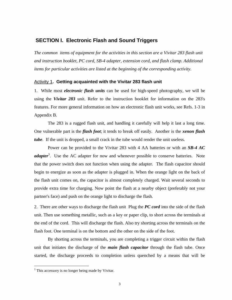
Background: An important factor to control for
high-speed photography is the flash duration,
that is, the amount of time the flash of light
lasts. Typically, one wants the shortest possible
burst of light. Fig. 1 shows the intensity of the
light vs. time for a full discharge. The intensity is
not constant but rather increases from 0 to a
maximum in about 0.3 ms4. It then decreases
more gradually over a period of about a milli-
4 The abbreviation, ms, stands for millisecond. The prefix, milli-, represents thousandths. Thus, 1 ms = 0.001 s(second).
5
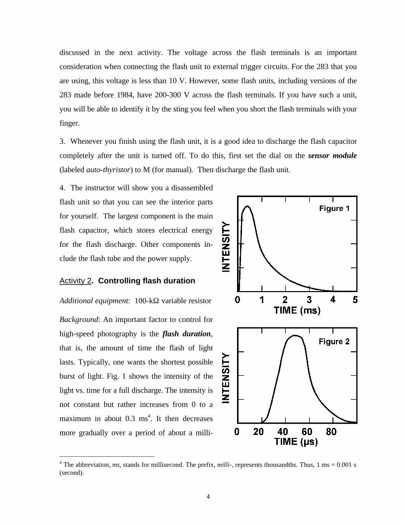
second. This is too long for high-speed photographs. However, if the flash unit is used in the
automatic exposure5 mode, the duration can be decreased to as little as 30 µs6. Such a
discharge is represented in Fig. 2. Note that the time scale is expanded by a factor of 50 over
that of Fig. 1. The intensity scale is expanded by about a factor of 10, pointing to the fact that
decreasing the duration of the flash also decreases the brightness. A 30-µs burst will be quite
dim compared to a full discharge. However, there will still be sufficient light for photography.
In order to obtain the briefest flash of light, you will need to arrange for the intensity
of the reflected light to be as great as possible7. In this activity, you’ll find out how to do that.
1. Note the small, circular window on the front of the auto-thyristor module. This window
allows light to reach a light detector8 inside the module. Light must reach this detector in or-
der for the flash unit to operate in its automatic mode. In the M (manual) setting, the window
is completely covered, and the flash unit produces its brightest and longest flash of light. For
each of the colored settings--yellow, blue, red, purple--a different neutral-density filter is ro-
tated in place over the light detector. These filters reduce the intensity of light reaching the
light detector. The darker the filter, the brighter and longer the flash of light will be.9 For high-
speed photography, the most transparent filter would be used in order to obtain the shortest
flash duration.
Which of the colored settings gives the shortest flash duration? Which gives the
longest? In order to find out, aim the flash unit at a distant wall, making sure to keep the
window over the light detector uncovered. Placing the flash unit in each of the colored
automatic modes in turn, discharge the flash unit. Which mode gave the brightest flash?
Which gave the dimmest? Remember that the brighter the flash, the longer it lasts.
2. Another way to change the amount of light reflected to the light detector is to change the
distance from the flash unit to the subject. Try this by discharging the flash when it is very
5 In the automatic mode, the light reflected by the subject is detected by a photoresistor in the auto-thyristormodule on the front of the 283. A small capacitor in series with the photoresistor charges through it. When thevoltage across the capacitor reaches some predetermined amount, the flash discharge is quenched.6 The abbreviation, µs, stands for microsecond. The prefix, micro-, represents millionths. Thus, 1 µs = 0.001ms = 0.000001 s.7 This results because the resistance of the photoresistor decreases as the light intensity increases. The lowerthe resistance, the quicker the series capacitor will charge.8 This is the photoresistor referred to in footnote 5.
6
close to the wall and then again when it is as far away as you can get it. Use the yellow auto-
matic mode. (You should have found that the yellow mode gives the shortest flash of light.)
Did you get the brighter flash when the unit was closer or farther from the wall? Can you ex-
plain why this result is to be expected?
What does this tell you about where you should place the flash unit for taking high-speed pho-
tographs?
3. A third way to change how much light is reflected to the light detector is to change the
background. A dark background will obviously reflect much less light than a white one at the
same distance. Try this by discharging the flash unit first toward a white wall and then toward
a black curtain at the same distance as the wall. What did you find out?
4. Of the second and third factors discussed above, the second is the more important. That’s
because a black background can still reflect a significant amount of light. It’s usually best to
set the auto-thyristor module on yellow and place the background as far away as possible
from the subject being photographed.
In order to review what you have done so far, what three things can you do in order to
obtain the shortest burst of light from the flash unit?
a.
b.
c.
9 One would use darker filters in order to use smaller apertures for greater depth-of-field. For high-speedphotography, however, the greater flash duration that results is usually undesirable.
7
In addition to minimizing flash duration, using the yellow automatic mode will
maximize battery life. Therefore, whenever possible when using batteries, be sure the flash
unit is placed in the yellow mode and that the flash head is in the 90° position so that the
reflected light reaches the light detector. Be sure, of course, that your hand doesn’t cover the
detector.
5. The Vivitar 283 has a feature that makes it possible to conveniently adjust flash duration.
Note that the auto-thyristor module can be removed. Pull it straight out, away from the flash
unit. This will expose an arrangement of five holes. The two holes on the right (as seen with
the flash unit upright and facing you) are the connections for the light detector. By inserting
the leads of a variable resistor into these two holes, you can control the flash duration (and
brightness) directly. Try this now with the 100-kΩ variable resistor.
Activity 3. Measuring flash duration
Additional equipment: 100-kΩ variable resistor AC motor with clock disc Ring stand and clamp Electronic stroboscope
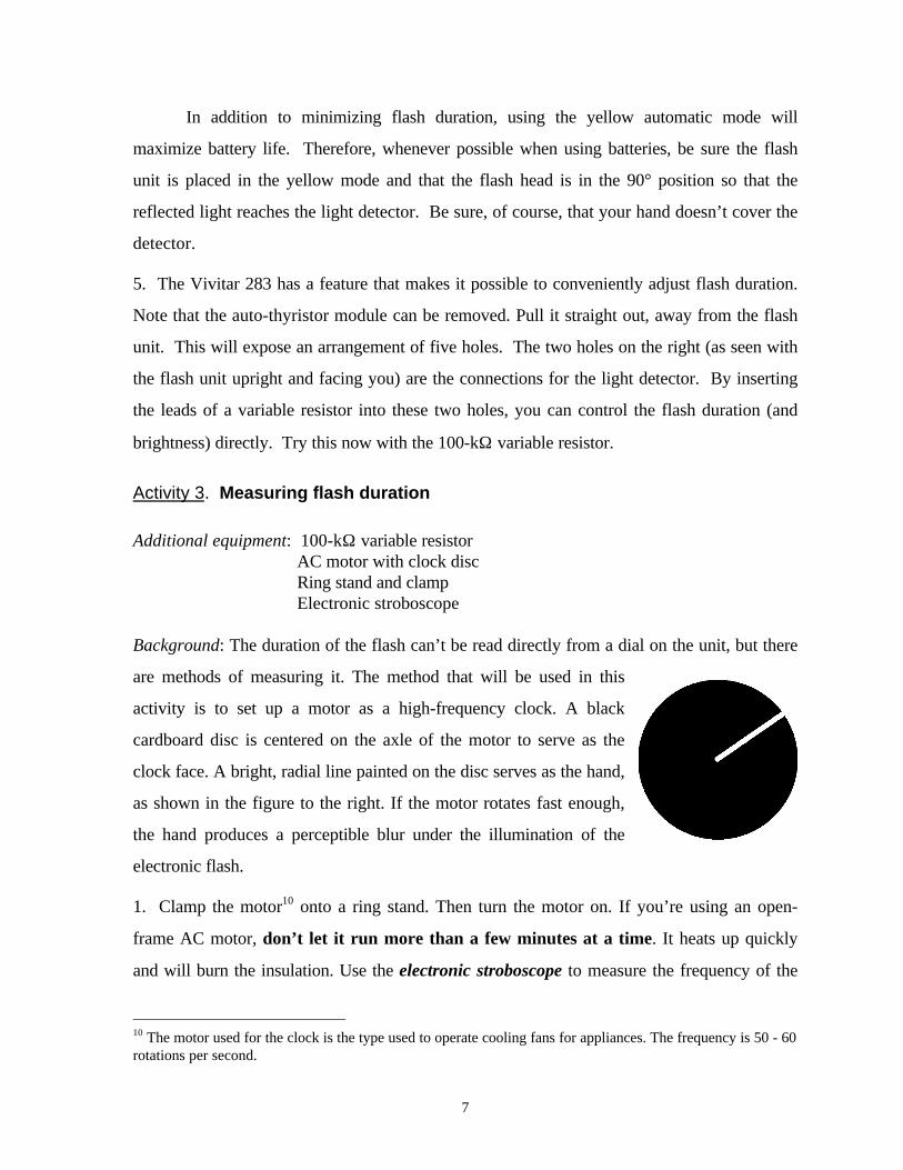
Background: The duration of the flash can’t be read directly from a dial on the unit, but there
are methods of measuring it. The method that will be used in this
activity is to set up a motor as a high-frequency clock. A black
cardboard disc is centered on the axle of the motor to serve as the
clock face. A bright, radial line painted on the disc serves as the hand,
as shown in the figure to the right. If the motor rotates fast enough,
the hand produces a perceptible blur under the illumination of the
electronic flash.
1. Clamp the motor10 onto a ring stand. Then turn the motor on. If you’re using an open-
frame AC motor, don’t let it run more than a few minutes at a time. It heats up quickly
and will burn the insulation. Use the electronic stroboscope to measure the frequency of the
10 The motor used for the clock is the type used to operate cooling fans for appliances. The frequency is 50 - 60rotations per second.
8
motor. This is done by adjusting the stroboscope frequency until the hand of the clock disc
appears stationary. To insure that the clock hand is making only a single rotation between
flashes, double the stroboscope frequency. If two equally-bright images of the hand are seen
180° apart, the original frequency was the correct one. Record the clock frequency in flashes
per minute. Then calculate the number of flashes per second.
Clock frequency (fpm) = Clock frequency (fps) =
2. Calculate how long it would take for the hand of the clock to move through an angle of
90°. Repeat for 1°.
3. In order to use the clock to make accurate measurements of flash duration, it’s necessary
to take photographs of the rotating disc. For this activity, however, you can simply view the
disc and make relative judgements about the angle through which the hand moves. Set the
flash unit on the purple automatic mode and point it at the rotating disc, about a meter away.
Discharge the unit, watching the disc as you do so. Back up to larger and larger distances
from the disc, noting the amount of blur each time. Then repeat with the flash unit set on the
yellow automatic mode. Also try with the auto-thyristor set on M. Finally, make some tests
with the 100-kΩ resistor replacing the auto-thyristor module. Give the results of the tests.
effect of increasing distance:
effect of yellow compared to purple:
effect of M setting:
effect of increasing variable resistance:
9
Activity 4. Triggering the flash unit with sound
Additional equipment: Piezoelectric sound triggerBalloon and pin
Background: You’ve already seen how to trigger a flash discharge by shorting across the flash
terminals. In this activity, you will use a sound trigger, a circuit that shorts the terminals elec-
tronically in response to sound.
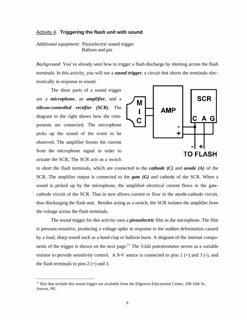
The three parts of a sound trigger
are a microphone, an amplifier, and a
silicon-controlled rectifier (SCR). The
diagram to the right shows how the com-
ponents are connected. The microphone
picks up the sound of the event to be
observed. The amplifier boosts the current
from the microphone signal in order to
actuate the SCR, The SCR acts as a switch
to short the flash terminals, which are connected to the cathode (C) and anode (A) of the
SCR. The amplifier output is connected to the gate (G) and cathode of the SCR. When a
sound is picked up by the microphone, the amplified electrical current flows in the gate-
cathode circuit of the SCR. That in turn allows current to flow in the anode-cathode circuit,
thus discharging the flash unit. Besides acting as a switch, the SCR isolates the amplifier from
the voltage across the flash terminals.
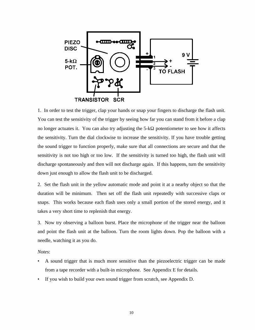
The sound trigger for this activity uses a piezoelectric film as the microphone. The film
is pressure-sensitive, producing a voltage spike in response to the sudden deformation caused
by a loud, sharp sound such as a hand clap or balloon burst. A diagram of the internal compo-
nents of the trigger is shown on the next page.11 The 5-kΩ potentiometer serves as a variable
resistor to provide sensitivity control. A 9-V source is connected to pins 1 (+) and 3 (-), and
the flash terminals to pins 2 (+) and 3.
11 Kits that include this sound trigger are available from the Edgerton Educational Center, 208 16th St.,Aurora, NE.
10
1. In order to test the trigger, clap your hands or snap your fingers to discharge the flash unit.
You can test the sensitivity of the trigger by seeing how far you can stand from it before a clap
no longer actuates it. You can also try adjusting the 5-kΩ potentiometer to see how it affects
the sensitivity. Turn the dial clockwise to increase the sensitivity. If you have trouble getting
the sound trigger to function properly, make sure that all connections are secure and that the
sensitivity is not too high or too low. If the sensitivity is turned too high, the flash unit will
discharge spontaneously and then will not discharge again. If this happens, turn the sensitivity
down just enough to allow the flash unit to be discharged.
2. Set the flash unit in the yellow automatic mode and point it at a nearby object so that the
duration will be minimum. Then set off the flash unit repeatedly with successive claps or
snaps. This works because each flash uses only a small portion of the stored energy, and it
takes a very short time to replenish that energy.
3. Now try observing a balloon burst. Place the microphone of the trigger near the balloon
and point the flash unit at the balloon. Turn the room lights down. Pop the balloon with a
needle, watching it as you do.
Notes:
• A sound trigger that is much more sensitive than the piezoelectric trigger can be made
from a tape recorder with a built-in microphone. See Appendix E for details.
• If you wish to build your own sound trigger from scratch, see Appendix D.
11
SECTION II. Photographic Techniques
In addition to the flash equipment used in the activities of the last section, those in this sec-
tion require a camera, film, and background cloth. A Vivitar flash accessory that may be
useful is an extender cord for the auto-thyristor module. If you are using a Polaroid camera,
see Appendix A.
Activity 5. Photographing bursting balloons and breaking bulbs
Additional equipment: Piezoelectric sound triggerBalloons, pin, light bulbs, safety glasses
Background: In this activity, you’ll learn the basics of taking photographs of high-speed
events using a single flash unit, triggered by sound.12 Before you take a photograph, there are
several decisions to be made.
• What camera, lens, and film will be used?
The answer to this question may depend on what you have available. There are only a few
requirements. The camera should have a B shutter setting and the lens should have
manually-adjustable aperture and focus. The choice of film is not critical. A medium speed
film (ISO 400) is sufficient for most purposes. The only advantage of higher film speeds is
to make it possible to use smaller lens apertures, thus increasing depth-of-field.
• How far from the subject to be photographed will the camera be?
Usually, one tries to place the camera as close as possible so that the image of the event to
be photographed will fill the frame of film. If the subject is small, the minimum focusing
distance of the camera may limit the size of the image.
• What background will be used and how far behind the subject will it be?
It is frequently desirable to have a dark, featureless background that will not distract at-
tention from the main subject. A sheet of dark cloth or paper can be placed behind the
12 If you’re not already familiar with the subjects of film exposure and depth-of-field, see Appendix C.
12
subject. The surface should be rough to minimize glare. The farther behind the subject the
background can be, the better. This will decrease the intensity of reflected light.
• Where will the flash unit be placed?
The flash unit is usually placed as close to the subject as possible, while still giving uniform
coverage. This increases the concentration of light on the subject, as needed when the
flash duration is short. One should also consider the angle at which the light strikes the
subject. By choosing the angle correctly, shadows can be produced that help to show
structure and texture in the subject. If the flash unit is placed on the hot shoe of the cam-
era, care must be taken that opening the shutter of the camera does not discharge the unit.
This can be done simply by putting a piece of tape over the center contact on the flash
foot.
• How far from the source of sound will the sound trigger be placed?
The greater the distance of the sound trigger from the source of sound, the longer the de-
lay will be before the flash discharges. If one is not sure how much delay is needed, the
trigger can initially be placed very close to the source and then moved farther away if nec-
essary.
• What lens aperture will be used?
If the flash unit is used on an automatic setting, the selection of the lens aperture is easy.
Set the calculator dial located on the side of the flash unit to the speed of the film being
used. Then read the aperture opposite the color of the automatic setting. This assumes
that the flash unit and camera are the same distance from the subject. If this is not the case,
the auto-thyristor module can be moved to the location of the camera using an auto-
thyristor extender cord. Ask the instructor for one.
Note: If you have substituted a variable resistor for the auto-thyristor module, you may
need to use trial-and-error in order to determine the correct exposure. Alternatively, you
can quickly determine exposure if you have access to a flash exposure meter.
13
1. Before taking photographs, you’ll need to prepare a table to record information about each
photograph that you take. With this data and the corresponding set of prints, you’ll be able to
decide how to make changes in your setup in order to improve the photographs for you next
roll of film. In addition, if you happen to discover something interesting, you’ll have the
record to corroborate your discovery. A table for your first roll of film is given on the next
page, and descriptions of the column headings follow that. Additional data pages are included
at the end of this manual.
2. Set up to take a photograph of a balloon burst. If you have a tripod, use it to mount your
camera. You may also find it convenient to use a flash clamp to clamp the flash to the table.
Be careful, though, to place it so that you are not prone to bump into as you move around.
3. Once you are set up, check to make sure that the lens aperture is correct, the camera shut-
ter is placed on B, and the lens is focused on the subject. Then turn out the room lights, hold
the shutter open, pop the balloon, close the shutter, and turn on the lights. Try again, using a
different sound trigger position to capture the burst in a different stage.
4. You can use the same setup as above to photograph the smash of a light bulb. Simply re-
place the balloon with a bulb. You could drop the bulb from a height onto the table or hit it
with a heavy object. As a safety precaution, wear safety glasses if you are close to the bulb.
You may find that the sound trigger has to be placed much further away than for a balloon
burst. This is because the bulb breaks much slower than the balloon bursts.

14
ROLL DESCRIPTION ______________________ ROLL ID ___________ DATE _____________
PHOTOGRAPHER _______________________________ CAMERA ________________________
CAMERA LENS ________________ FILM USED _____________ FILM SPEED _____________
FLASH UNIT USED ___________________
Give any additional information and a sketch of the photographic setup on the back.
FRAMECOUNT.
NEG.NO.
APER-TURE
FLASHMODE
FLASHDIST.
CAMERADIST.
TRIGGERDIST.
SUBJECT DESCRIPTION
15
Descriptions of column headings
ROLL DESCRIPTION: Give a descriptive title to identify the roll of film being shot (forexample, Needle bursts of air balloons)
ROLL ID: Give a shorthand code to identify each roll (for example, LW-1)
DATE: Give the date or dates when the photos were taken.
PHOTOGRAPHER: Your own name and any other direct contributors to the photos
CAMERA: Manufacturer and model of the camera used
CAMERA LENS: Manufacturer, model, and focal length of the lens used
FILM USED: Manufacturer and type of film used
FILM SPEED: ISO number of the film
FLASH UNIT USED: Manufacturer and model of the camera used
List data in the table consecutively as you take photographs. Be sure to include a line in thetable for each frame advance of the film. If, for example, the flash doesn't fire, indicate that inthe appropriate line of the data table.
FRAME COUNT: the number given by the frame counter of your camera.
NEG NO: Fill this in after you get your film developed. It's the number on the film that iden-tifies each frame. This number may differ from the frame counter.
APERTURE: f-stop selected for the photograph
FLASH MODE: exposure mode of the flash unit (for example, auto yellow)
For the three distances below, be sure to indicate units of measurement (for example, feet ormeters)
FLASH DISTANCE: distance from the flash unit to the subject of the photograph
CAMERA DISTANCE: distance from the camera to the subject
TRIGGER DISTANCE: distance from the sound trigger to the subject
SUBJECT DESCRIPTION: Describe what you photographed. Tell enough to allow you tomatch the negative with the data (for example: red air balloon, late rip)
16
Activity 6. Photographing the smash of a tennis ball or racquetball
Additional equipment: Piezoelectric sound triggerTennis ball or racquetball and racketLarge cloth sheet or blanket
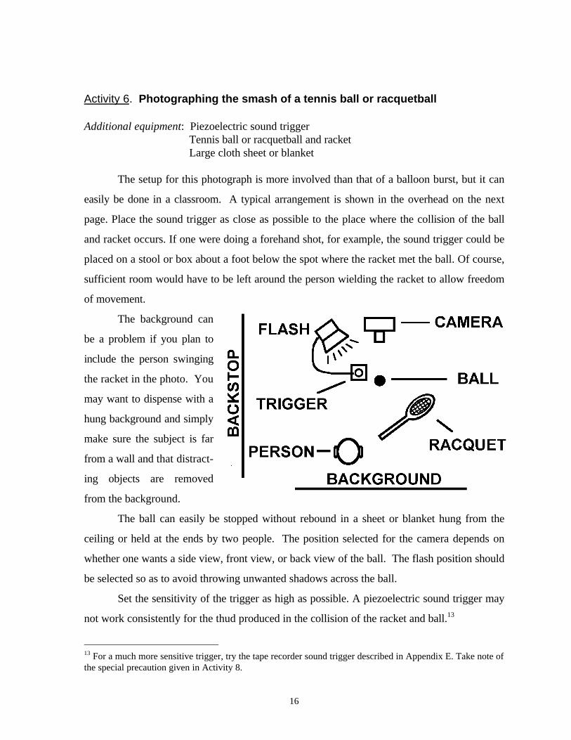
The setup for this photograph is more involved than that of a balloon burst, but it can
easily be done in a classroom. A typical arrangement is shown in the overhead on the next
page. Place the sound trigger as close as possible to the place where the collision of the ball
and racket occurs. If one were doing a forehand shot, for example, the sound trigger could be
placed on a stool or box about a foot below the spot where the racket met the ball. Of course,
sufficient room would have to be left around the person wielding the racket to allow freedom
of movement.
The background can
be a problem if you plan to
include the person swinging
the racket in the photo. You
may want to dispense with a
hung background and simply
make sure the subject is far
from a wall and that distract-
ing objects are removed
from the background.
The ball can easily be stopped without rebound in a sheet or blanket hung from the
ceiling or held at the ends by two people. The position selected for the camera depends on
whether one wants a side view, front view, or back view of the ball. The flash position should
be selected so as to avoid throwing unwanted shadows across the ball.
Set the sensitivity of the trigger as high as possible. A piezoelectric sound trigger may
not work consistently for the thud produced in the collision of the racket and ball.13
13 For a much more sensitive trigger, try the tape recorder sound trigger described in Appendix E. Take note ofthe special precaution given in Activity 8.
17
Before attempting photographs, have the person who swings the racket take some
practice swings with the room lights on. Then repeat with the lights off. If the room is too
dark, a penlight can be used to illuminate the ball during the swing. The flash will probably be
bright enough in comparison so that the light from the penlight is not noticeable.
If you wish, try different camera, flash, and sound trigger positions in order to examine
how the shape of the ball changes throughout a collision. Also, compare the deformation of a
tennis ball to that of a racquetball, which is much softer than a tennis ball.
Activity 7. Using a contact trigger to capture a football kick
Additional equipment: 1-2 m long hookup wiresAluminum foilFootball and teeBackstop blanket
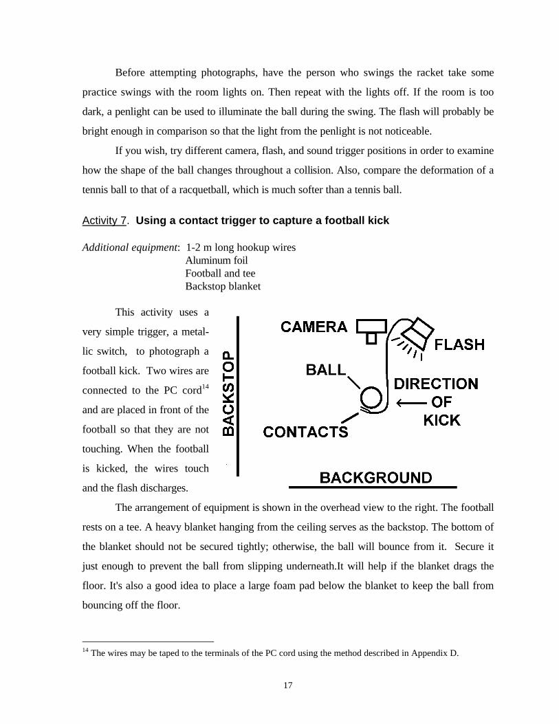
This activity uses a
very simple trigger, a metal-
lic switch, to photograph a
football kick. Two wires are
connected to the PC cord14
and are placed in front of the
football so that they are not
touching. When the football
is kicked, the wires touch
and the flash discharges.
The arrangement of equipment is shown in the overhead view to the right. The football
rests on a tee. A heavy blanket hanging from the ceiling serves as the backstop. The bottom of
the blanket should not be secured tightly; otherwise, the ball will bounce from it. Secure it
just enough to prevent the ball from slipping underneath.It will help if the blanket drags the
floor. It's also a good idea to place a large foam pad below the blanket to keep the ball from
bouncing off the floor.
14 The wires may be taped to the terminals of the PC cord using the method described in Appendix D.
18
The camera may rest on the floor or be raised with a stack of books. The flash is
placed nearby. The wires from the PC cord should be taped in place in front of the ball (or just
to the side if you don't want the wires in the photograph). Small strips of aluminum foil can be
taped to the bare ends of the wires to provide greater contact area. When the ball is kicked, it
should force the wires into contact and set off the flash unit. You may want to experiment
with the positioning of the wires in order to capture the football at different stages during the
kick.
Activity 8. Photographing waveforms on an elastic band
Additional equipment: Tape recorder sound triggerLarge rubber band
With a sensitive sound trigger, a snapped elastic band can be observed almost immedi-
ately after its release. The tape recorder sound trigger described in Appendix E works particu-
larly well for this.
Use a large rubber band or a length of elastic cord. If you use a rubber band, cut it so
that you can stretch it end-to-end. Hold the microphone of the tape recorder near the point
where the band will be plucked. Aim the flash unit at the band. When the band is plucked and
the flash discharges, the initial waveform can be observed.15 To observe the waveform at a
later time, move the microphone further from the release point of the cord.
If photographs are to be taken, one must be aware that the small size of the subject
will fool the flash unit's automatic exposure circuit. The exposure of the film will be
determined primarily by the light reflected from the background. This will quench the flash
discharge later than needed for correct exposure of the cord. The problem can be minimized
by hanging a background (even a dark one) within about a meter of the cord. One could also
try photographing a shadow of the cord cast on a white background.
Special precaution: Another problem in taking photographs is that the click of the camera
shutter may actuate the sound trigger prematurely, giving unwanted exposures. To avoid this,
hold a hand over the camera lens while opening the shutter.
15 For an explanation of the interesting waveforms produced on the cord, see Refs. 9 and 10 in Appendix B.
19
SECTION III. Photogate Triggers and Delay Units
The common items of equipment for the activities in this section are a Vivitar 283 flash unit
and instruction booklet, PC cord, SB-4 adapter, extension cord, flash clamp, camera, film,
and background cloth. Additional items for particular activities are listed at the beginning of
the corresponding activity.
Activity 9. Using an interrupter photogate to observe a plucked cord
Additional equipment: Interrupter photogate triggerElastic cord (approx. 1/8” diameter and 0.5 m long)Two supports for the cord
Background: A photogate consists of an emitter and detector of light aimed at each other.
The emitter may produce a beam of visible or infrared light. The interruption of the beam
serves as the triggering event. The emitter may be a light-emitting diode (LED), a laser, or a
beam of white light from, say, a penlight. The detector is a phototransistor, serving as a vari-
able resistor whose resistance depends on the intensity of detected light.
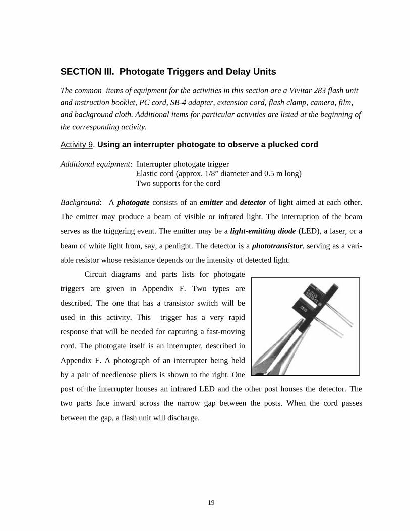
Circuit diagrams and parts lists for photogate
triggers are given in Appendix F. Two types are
described. The one that has a transistor switch will be
used in this activity. This trigger has a very rapid
response that will be needed for capturing a fast-moving
cord. The photogate itself is an interrupter, described in
Appendix F. A photograph of an interrupter being held
by a pair of needlenose pliers is shown to the right. One
post of the interrupter houses an infrared LED and the other post houses the detector. The
two parts face inward across the narrow gap between the posts. When the cord passes
between the gap, a flash unit will discharge.
20
If you did Activity 8, you used a sensitive sound trigger to observe the shape of a
plucked, elastic cord. In this activity, the interrupter photogate will be used for observing the
shape.16
1. You’ll first need to adjust the photogate trigger for maximum sensitivity. Turn the sensitiv-
ity knob (or variable resistance) one way or the other until the flash discharges spontaneously.
Then back off slightly to the point where the flash will discharge when something is passed
through the gap of the interrupter. What you have done is found the threshold for spontane-
ous triggering. As long as the resistor is just below the threshold, the trigger will be at its most
sensitive. Above the threshold, the trigger will not function.
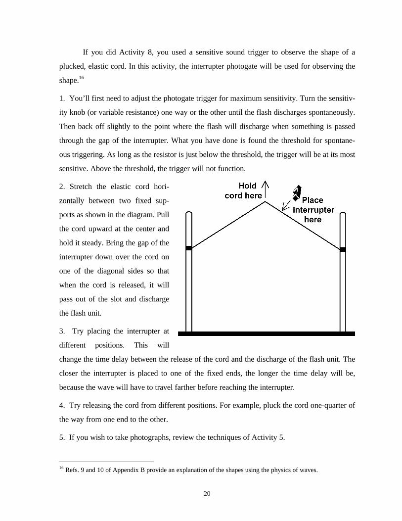
2. Stretch the elastic cord hori-
zontally between two fixed sup-
ports as shown in the diagram. Pull
the cord upward at the center and
hold it steady. Bring the gap of the
interrupter down over the cord on
one of the diagonal sides so that
when the cord is released, it will
pass out of the slot and discharge
the flash unit.
3. Try placing the interrupter at
different positions. This will
change the time delay between the release of the cord and the discharge of the flash unit. The
closer the interrupter is placed to one of the fixed ends, the longer the time delay will be,
because the wave will have to travel farther before reaching the interrupter.
4. Try releasing the cord from different positions. For example, pluck the cord one-quarter of
the way from one end to the other.
5. If you wish to take photographs, review the techniques of Activity 5.
16 Refs. 9 and 10 of Appendix B provide an explanation of the shapes using the physics of waves.
21
Activity 10. Capturing vertical jumps with a photogate
Additional equipment: Photogate trigger (transistor type)Jumping discs
Background: The discs that you will use in this activity are made from bimetallic strips. The
top and bottom of each disc are actually made of thin pieces of two different metals such as
brass and iron. These metals expand (or contract) at different rates when heated (or cooled).
This effect makes it possible for a disc to jump off a table on its own. The disc has two states
which can be obtained by snapping the center of the disc in or out. The disc naturally snaps
into its low-energy state when left on its own. In order to make the disc work, snap it into its
high-energy state and hold it there while heating it in your hand. Then place the disc, convex
upward, on a cool surface. As the disc cools, the metal on top contracts faster than the metal
on the bottom. This soon causes the disc to snap back to its low-energy state. When it does
so, the middle part pushes off of the table, causing the disc to jump. While the disc used in this
activity is a novelty, bimetallic strips are extremely important as temperature sensors in heat-
ing systems.
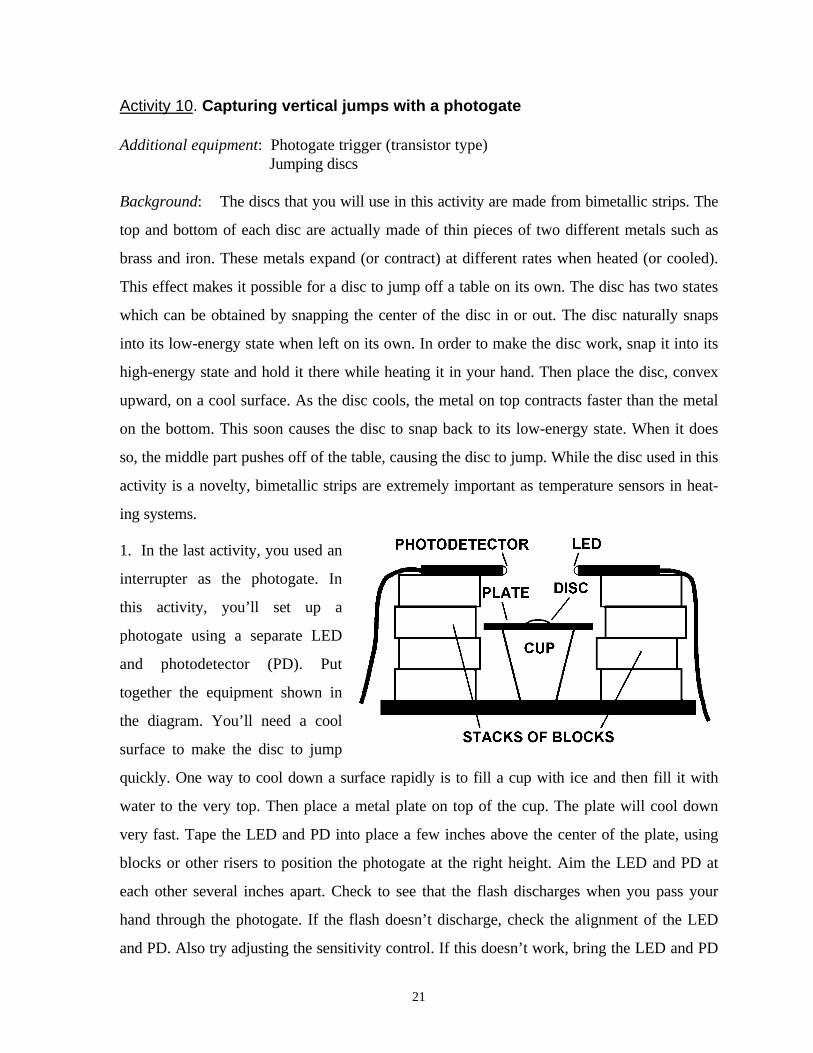
1. In the last activity, you used an
interrupter as the photogate. In
this activity, you’ll set up a
photogate using a separate LED
and photodetector (PD). Put
together the equipment shown in
the diagram. You’ll need a cool
surface to make the disc to jump
quickly. One way to cool down a surface rapidly is to fill a cup with ice and then fill it with
water to the very top. Then place a metal plate on top of the cup. The plate will cool down
very fast. Tape the LED and PD into place a few inches above the center of the plate, using
blocks or other risers to position the photogate at the right height. Aim the LED and PD at
each other several inches apart. Check to see that the flash discharges when you pass your
hand through the photogate. If the flash doesn’t discharge, check the alignment of the LED
and PD. Also try adjusting the sensitivity control. If this doesn’t work, bring the LED and PD
22
close together, about an inch apart. Once you get the photogate working, then you can move
the two parts away from each other gradually, checking to make sure that the photogate
continues to work. When you have the LED and PD positioned where you want them, adjust
the sensitivity for a maximum as described in Activity 9.
2. Prepare a disc for jumping as described in the Background. Then place it in the center of
the metal plate. When it jumps and passes through the photogate, the flash unit will discharge
and you’ll be able to see the disc. Does the disc flip as it jumps? You can try placing the pho-
togate at different heights in order to see the disc in different parts of its jump.17 You can also
try putting several discs on the plate at once. They won’t all jump at the same time, so you can
see them one after the other.
A related activity--Capturing the burst of a popcorn kernel: If you can capture a jumping
disc with a photogate, you can also capture a jumping popcorn kernel as it pops. This is easi-
est to do by heating one kernel at a time on a hot plate. You’ll need to put your LED and PD
far apart and just above the surface of the hot plate. This will require some careful adjusting.
Do this before turning on the hot plate so that you don’t burn yourself.
A good way to heat a single kernel is to place it inside a small iron washer and then
put a few drops of cooking oil inside the washer. Position the washer so that the kernel will
pass through the photogate as it’s jumping off the hot plate. Most kernels open very rapidly,
so you’ll probably see the kernel bursting open.
You may find that the spray of oil from the burst can break the infrared beam prema-
turely. If so, decrease the sensitivity of the detector so that tiny oil globules will not trigger
the flash unit.
One problem with taking photos of bursting popcorn kernels is that you’re never sure
when they’re going to pop. You may have to hold the shutter of your camera open for a long
time in the dark room, waiting for the kernel to pop. After a while, you may learn to anticipate
when a kernel is going to pop so that you can open the shutter just before that. Some variables
that you’ll learn to optimize if you work long enough are the temperature of the griddle and
17 You’ll learn in the next activity how to use an electronic circuit to create a time delay between theinterruption of the photogate and the discharge of the flash unit. If you already know how to use this circuit,you could use it with the jumping disc.
23
the amount of oil that you drop in the washer. You need to be patient and be willing to make
many trials. You may want to try placing the photogate at different heights above the hot plate
so that you can capture a kernel later in its burst. Be careful not get cooking oil spray on your
camera and, more importantly, in your eyes. It may be a good idea to wear glasses or goggles.
Activity 11. Using an electronic delay with a contact trigger
Additional equipment: Electronic delay unit with selection of capacitorsContact triggerRubber ballSquish ballWater balloon
Background: When using a photogate trigger, the flash discharges as soon as the beam is
broken. For some situations, it may be desirable to have a time delay between the breaking of
the beam and the discharge of the flash unit. For example, if a ball were dropped through the
photogate, a delay would be necessary in order to capture the ball as it collided with a table or
the floor. A delay circuit that can be used with the photogate trigger is described in Appendix
G. The purpose of this activity will be to learn how to use the electronic delay with another
type of trigger, called a contact trigger. A contact trigger is simply composed of two metal
strips or plates that are normally held a small distance apart by an insulator. The two plates are
connected with wires to the PC cord of a flash unit. When the plates are forced together by,
say, a colliding object, the flash unit will discharge. A method of making a contact trigger such
as the one that will be used in this activity is described in Appendix H.
1. Connect a flash unit to output 2 of the delay box. Connect the leads of a 1-µf capacitor to
the clips on the side of the box. This capacitor and the setting of the variable resistor deter-
mine the length of the delay. Turn the resistor to mid range. Then push the test button to
trigger the flash unit. You should notice a short delay before the flash unit discharges. Try
turning the resistor to different values to see how that affects the delay. What is the maximum
value of the delay?18 the minimum value? You’ll probably find that when the resistor is turned
18 The delay (in seconds) is approximately equal to the product of the capacitance (in µf) and the setting of thevariable resistor (in MΩ). If the meximum value of the variable resistor is 1 MΩ, as in the circuit of AppendixG, then the maximum time delay with a 1-µf capacitor is 1 second.
24
too low, the flash will not discharge at all. Now replace the 1-µf capacitor with the 0.1-µf
one. Is the delay noticeable? Whenever using the delay box, you’ll need to decide what
capacitor to use in order to get best results.
2. Place the contact trigger on a table. Connect the wire leads to the input of the delay box.
Aim the flash unit so that it will illuminate a ball as it strikes the table. A squish ball (available
at some toy stores) works best for short drops. Use the delay box, with an appropriate capaci-
tor selection, to observe the collision of the ball with the trigger at different times after con-
tact. Some trial and error may be necessary to determine which capacitor is best. The best
selection will allow you to scan the entire time interval of the collision--but not much more
than that--by turning the variable resistor through its entire range. One problem that you may
notice in using the contact trigger is that the flash unit discharges on consecutive bounces of
the ball. Turn on the reset delay switch to eliminate these unwanted flash discharges.19
3. Try dropping a water balloon onto the trigger. First, put the contact trigger into a plastic
bag with only the wires coming out. Seal the bag well to keep water from leaking into it. Set
the trigger on a slightly raised platform in a tray to catch water in case the balloon breaks.
You can probably use the same capacitor as for the squish ball. The water balloon takes on an
interesting variety of shapes will it is collapsing onto the trigger and also while it is rebound-
ing. Be sure to scan the entire time interval of the collision and a little beyond.
Note: You may wish to calibrate the delay unit so that you know the values of the delays for
various resistor settings. This can be done by connecting flash units to both of the outputs
and measuring the time interval between flash discharges with a high-speed clock. (See
Activity 3.)
Activity 12. Plucked cords and rubber bands
Additional equipment: Bracket photogatePhotogate trigger (transistor type) and cord to delay unitElectronic delay unit with selection of capacitorsElastic cordTwo supports for the cord
19 See Appendix G for to find out how different reset delay times are achieved.

25
Rubber band gun
Background: In Activity 9, you used an interrupter
photogate to observe waveforms on a plucked, elastic
cord. You achieved different delays by moving the
interrupter to various positions along the cord. In this
activity, you’ll use a bracket-type photogate in a fixed
position in order to obtain a wider range of delays. The
bracket holds the infrared LED and photodetector farther apart than the interrupter, thus
allowing larger objects to pass through.
1. In order to observe waveforms
on an elastic cord, connect the
photogate to the delay unit. Use a
0.01-µf capacitor with the delay
unit, and connect the flash unit to
output 2. Adjust the photogate to
maximum sensitivity as described
in Activity 9. Set up the ar-
rangement shown to the right. Tape the photogate to the tabletop and stretch the cord be-
tween two fixed supports. Pull the cord down into the bracket and release it in order to dis-
charge the flash unit. Adjust the delay in order to show the cord at different times after re-
lease. If you need greater delay times, use a larger capacitor. Adding a second 0.01-µf capaci-
tor in parallel with the first will double the maximum delay time.
2. If you have a rubber band gun, hold the end of the barrel near the photogate and fire a rub-
ber band through the photogate. Adjust the delay to show the band at various times after it
leaves the gun.
Activity 13. Photographing splashes
Additional equipment: Photogate trigger (Schmitt trigger type) and cord to delay unitElectronic delay with 0.5-µf capacitor2 support stands for LED and photodetector
26
Milk, dropper, ball, bucket of water or aquarium tank
The Schmitt trigger photogate described in Appendix F works best for this activity.
Set up a photogate with separate infrared LED and photodetector facing each other about half
an inch apart and about a foot above the table top. Connect the output of the photogate to the
input of the delay box, and connect output 2 of the delay box to a flash unit. Adjust the pho-
togate for maximum sensitivity. Release a milk drop just above the gate. Adjust the delay so
that you can capture the drop as it strikes the table. The 0.5-uf capacitor will provide delays
up to about a half second.
Since the milk drop is small, you may not be able to get close enough to produce a
large image of the splash on film. In order to produce a bigger splash, drop a ball into a bucket
of water. By adjusting the delay, you should be able to see the circular wall of water that
forms as the ball is breaking the surface. At slightly later times, you may be able to capture
the jet of water that rises vertically as the water rushes inward to close the cavity formed by
the ball. If you drop the ball into an aquarium of water and aim the flash unit through the side,
you can adjust the delay to see the path of the ball in the water.
Activity 14. Using a light slave
Additional equipment: Electronic delay unit and capacitor selectionNPN phototransistor (e.g. TIL414)Second flash unit
A light slave is a trigger that sets off one flash unit in response to the flash of light
from another. These are often used by photographers to illuminate a subject with more than
one flash unit without the need of long cords. The master flash unit may be used on the
camera hot shoe and the slave unit positioned to the side.
The delay box can serve as a light slave simply by connecting an NPN phototransistor
to the input. Connect the emitter to the positive side of the input and the collector to the nega-
tive. In this configuration, a flash of light on the transistor will have the effect of dropping the
voltage across it, thus triggering the delay circuit.
Using the delay box as a light slave makes it possible to interject a time delay between
the discharge of the master and slave flash units. Use one flash unit directly on your camera so
27
that it discharges upon pressing the shutter. Use the second flash unit, connected to output 2
of the delay box, off the camera. Of course, you’ll have to select a shutter speed long enough
so that the slave unit discharges before the shutter closes. And you’ll have to pick relatively
slow-moving objects since you have to trigger the shutter manually.
If you have a camera with an electronic shutter release, you may want to try
connecting a trigger (contact, sound, or photogate) to the input of the shutter release. In that
way, the event that you are photographing will trip the camera. This would make it possible to
work in a room with subdued lighting, since the shutter would not be open for long. Keep in
mind, though, that for most cameras there is a significant delay (hundredths of a second)
between the trigger signal and the opening of the shutter.
Note: By using the delay box as a light slave and connecting a single flash unit to output 2,
you can cause the flash to trigger repetitively on its own flashes of light. There is, however, a
minimum delay which is influenced by the recycling time of the flash unit.
28
SECTION IV. Measuring Small Time Intervals and High Speeds
In addition to a camera and accessories, the activities in this section require two 283 flash
units and accessories. The high-frequency clock described in Activity 3 is needed for timing.
While a stroboscope is convenient for frequency measurement, an alternative is described at
the end of Activity 15.
Activity 15. Speed of sound
Additional equipment: 2 piezoelectric sound triggersMeter stick and protractor2 wooden blocks
Note: Before doing this activity, try Problem 1 in Appendix I for practice.
1. For this and the next activity, you’ll be using two sound triggers and two flash units. Set
up the high-speed clock as you did in Activity 3 and measure its frequency. In that activity
you were measuring the duration of a single flash. In this activity, you’ll measure the time in-
terval between two flash discharges to use in determining the speed of sound.
Frequency of clock =
2. Connect a sound trigger to each flash unit (in yellow automatic mode) and arrange them so
that they illuminate the clock disc. Adjust each trigger for maximum sensitivity. (Note that if
the sensitivity is too high, the flash will not discharge at all.) Place both triggers next to each
other and stand about a meter away. Clap the blocks together, watching the rotating clock
disc while you are doing this. If the two triggers have identical sensitivities, the flash units will
discharge simultaneously, giving a single image of the radial line on the disc. If you see two
images separated by more than a few degrees, adjust the sensitivity of one trigger until it
matches that of the other. (In order to determine which flash discharged first, put a piece of
colored acetate film--such as a report cover--over one of the flash units.)
29
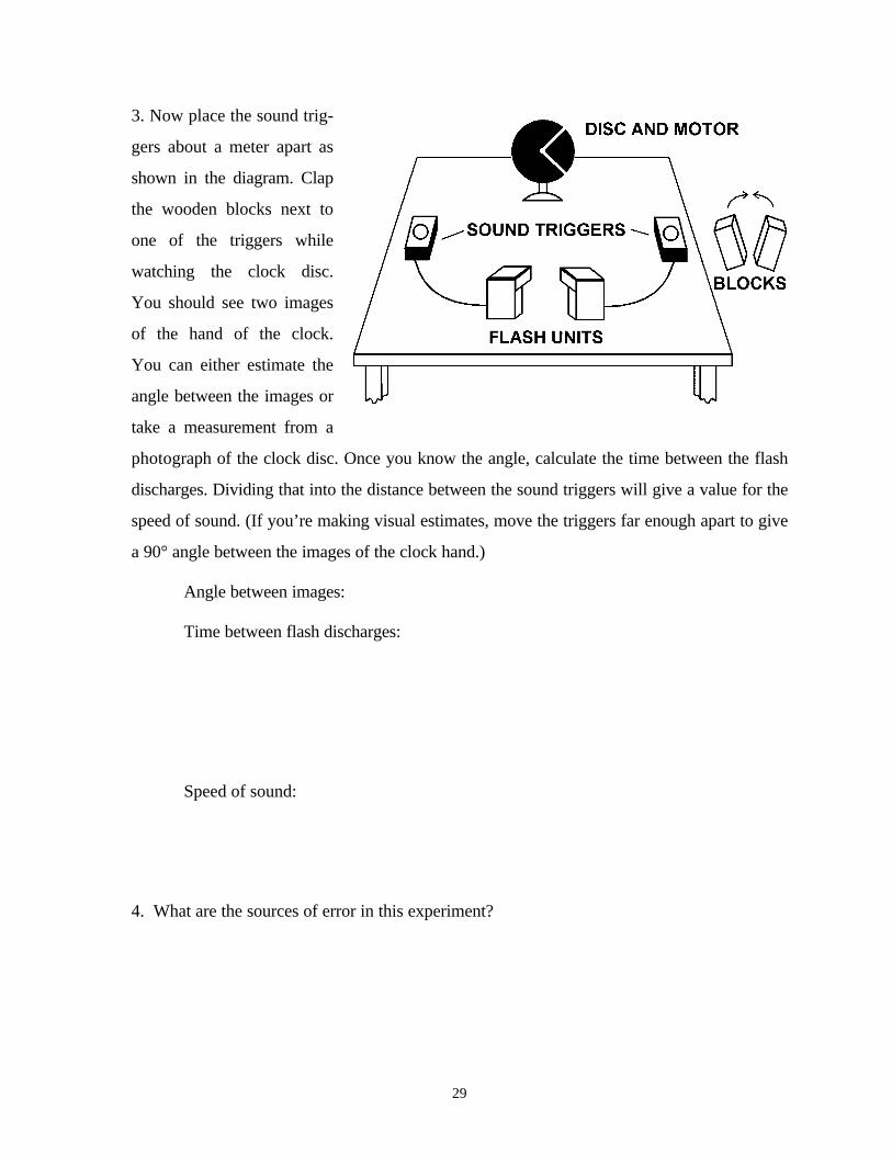
3. Now place the sound trig-
gers about a meter apart as
shown in the diagram. Clap
the wooden blocks next to
one of the triggers while
watching the clock disc.
You should see two images
of the hand of the clock.
You can either estimate the
angle between the images or
take a measurement from a
photograph of the clock disc. Once you know the angle, calculate the time between the flash
discharges. Dividing that into the distance between the sound triggers will give a value for the
speed of sound. (If you’re making visual estimates, move the triggers far enough apart to give
a 90° angle between the images of the clock hand.)
Angle between images:
Time between flash discharges:
Speed of sound:
4. What are the sources of error in this experiment?
30
An alternative frequency measurement: Frequency can be measured using an infrared photo-
gate interfaced to a computer. Punch a hole near the edge of the clock disc. Then position the
photogate so that the hole passes through the gate once per rotation.
Activity 16. Speed of a balloon rip
Additonal equipment: 2 piezoelectric sound triggersMeter stick and protractorLarge balloon, preferably cylindricalNeedle or pin
Note: Before doing this activity, try Problem 2 in Appendix I for practice. The photograph for
that problem will also help in setting up the experiment.
1. The setup for this activity is similar to that of the previous one. Blow up a large balloon,
and place sound triggers at both ends of it. Situate the clock disc above the front edge of the
balloon and as nearly parallel to the film plane of the camera as possible. (See the photograph
in Appendix I.) Place both flash units next to each other and just to the right out of the picure.
The reason for this placement is so that the shadows cast by the rips will contrast with the rips
themselves. Use the yellow automatic range, and close the lens aperture 1 stop from that indi-
cated by the calculator dial. This corrects for the fact that the balloon will be illuminated by
two flashes of light.
2. Prepare for a photograph and puncture the balloon near the left end. Make an enlargement
of the negative and determine the speed of the rip according to the method of Problem 2.
(Remember, you will need to know the diameter of the clock disc.)
Note: If you take photographs with a Polaroid camera, see Appendix A for suggestions. In
determining exposure, remember that in this experiment each exposure results from two
flashes of light.
31
APPENDICES
Appendix A. Using Polaroid cameras
Two Polaroid cameras that are often used for general recording purposes are the EESpecial and the 240 Automatic Land. These cameras can also be used with electronic flash forhigh-speed photography. One should use type 667 film, an ISO-3000 black-and-white film.Getting good exposures can be tricky, since neither camera has an aperture ring. Also, thecameras cannot be placed closer than 1 m from the subject. On the EE Special, the lens is fo-cused by turning a dial on the lens to the measured camera-to-subject distance. On the 240Land, a lever near the shutter button is pushed back-and-forth, and a rangefinder is used todetermine the best focus.
Both cameras have a photoelectric cell that measures ambient light and automaticallyadjusts the shutter speed for proper exposure. For high-speed photography, this cell should becovered with something opaque. This will allow the shutter to be held open as long as neces-sary in readiness for the flash discharge.
Given below are recommendations for obtaining good exposures with these cameras.It is assumed that a Vivitar 283 flash unit is placed half as far from the subject as the camera isand that the unit is set for minimum intensity and duration (see Activity 2). If the camera wereplaced at its closest focusing distance of 1 m, the flash unit would then be half a meter away.These would be typical conditions for many photographic situations.
Polaroid EE Special Camera
Set the slide bar on top of the camera to the 3000ER setting. If the photograph isoverexposed, you can reduce the exposure by holding a neutral density filter over the front ofthe lens during the exposure. Unfortunately, the only other control over exposure is to changethe flash-to-subject distance.
240 Automatic Land Camera
Set the film speed dial under the lens to 3000. Beside this dial is a lever that selectstwo different lighting situations. The settings are read on a panel above the lens. Set this leverto Outdoors or Flash.
Another possibility is to set the film speed to a much lower value, say, 150. Then, setthe lighting selector to Bright Sun. If the photo is over- or under-exposed, the film speed dialmay be adjusted either to 300 or 75.
32
Appendix B. References
1. James Bailey, How to select and use Electronic Flash (HP Books, Tucson, AZ, 1983).
2. Lester Lefkowitz, The Kodak Workshop Series: Electronic Flash, (Eastman Kodak,Rochester, 1986).
3. Harold E. Edgerton, Electronic Flash, Strobe (The MIT Press, Cambridge, MA, 1983),pp. 24-32.
4. M. L. Berry, "Stop Action Photography," The Physics Teacher 13, 418 (1975).
5. Harold E. Edgerton and James R. Killian, Jr., Moments of Vision: The StroboscopicRevolution in Photography (The MIT Press, Cambridge, MA, 1985).
6. Estelle Jussim and Gus Kayafas, Stopping Time, (Abrams, New York, 1987).
7. Stephen Dalton, Split Second, (Salem House, Salem, NH, 1984).
8. Loren M. Winters, "High-Speed Photography with Sound Triggers", The Physics Teacher28, 12 (1990).
9. Philip M. Morse, Vibration and Sound, (American Institute of Physics, 1976), pp.71-89.
10. Judith C. Brown, "Time-dependent behavior of strings using Fourier analysis," AmericanJournal of Physics 54, 125 (1986).
11. David L. Vernier, How to Build a Better Mousetrap, (Vernier Software, Portland, 1986),p. 1-14.
12. Forrest M. Mims III, 555 Timer IC Circuits, Radio Shack publication, p. 10.
33
Appendix C. Photographic Basics
Selecting aperture (f-stop)
If you want to take good high-speed photographs consistently, one thing you need toknow is how to select the aperture of your camera lens. On most lenses, the aperture dial hasa sequence of numbers 22, 16, 11, 8, 5.6, 4, 2.8, 2, 1.4, 1.0. These numbers are called f-stopsand are written f/22, f/16, etc. Some lens won't go as high as 22 and most won't go as low as1.0. The f-stop is related to the size of the aperture in an inverse way; that is, the larger the f-stop, the smaller the aperture.
It's useful to know how many times more light one aperture lets in than another. Forexample, f/4 lets in twice as much light as f/5.6, f/5.6 lets in twice as much as f/8, and f/22 letsin half as much as f/16. Here's a problem showing how you might use this knowledge in flashphotography.
Problem: Suppose you've determined that f/5.6 is the best f-stop to use for taking a high-speed photograph of a bursting balloon using Kodak Gold 400 film. Another personwants to take a photograph of the same subject, but she has Kodak Gold 100 film. Whatf-stop should she select?
Solution: Each film has an ISO rating which indicates its sensitivity to light. (Gold 400has ISO 400 while Gold 100 has ISO 100.) ISO 400 film is four times as sensitive to lightas ISO 100. This means that the ISO 100 film requires four times as much light to pro-duce the same exposure as the ISO 400 film. The way to get four times the light is toopen the aperture wider. f/4 would give twice as much light as f/5.6. Using f/2.8 wouldgive another factor of two more light. Altogether, that would be 2x2 = 4 times as muchlight.
Depth-of-field
The aperture that you select for a photograph affects two things: 1) the exposure ofthe film and 2) the depth-of-field. Depth-of-field refers to the range of distances in front ofand behind the subject that will be in acceptable focus in the photograph. There are two waysto increase depth-of-field when using a particular lens:
a. use a smaller aperture (larger f-stop),b. move farther from the subject,
Suppose that you're photographing a balloon burst and you want the balloon to be infocus from front-to-back. You may not want to move too far from the balloon, because youwant it to appear large in the photograph. That means you would need to use a smaller aper-ture. This may require you to use a more sensitive film, that is, one with a larger ISO rating.(See problem above.)
34
Appendix D. Building your own sound trigger
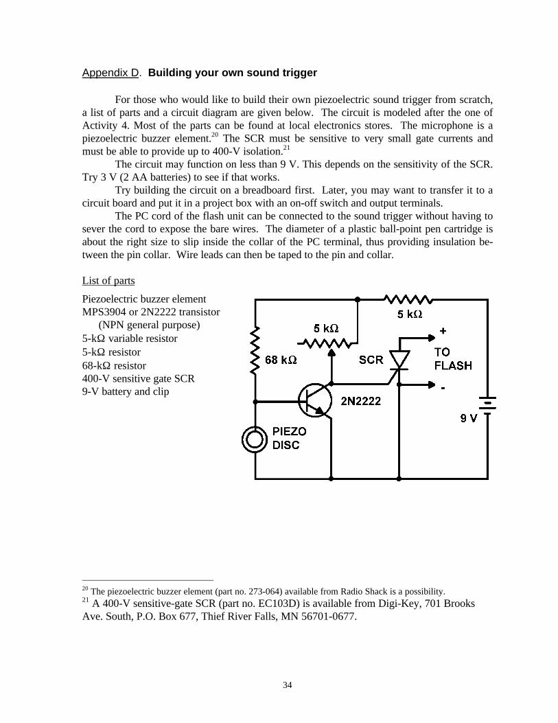
For those who would like to build their own piezoelectric sound trigger from scratch,a list of parts and a circuit diagram are given below. The circuit is modeled after the one ofActivity 4. Most of the parts can be found at local electronics stores. The microphone is apiezoelectric buzzer element.20 The SCR must be sensitive to very small gate currents andmust be able to provide up to 400-V isolation.21
The circuit may function on less than 9 V. This depends on the sensitivity of the SCR.Try 3 V (2 AA batteries) to see if that works.
Try building the circuit on a breadboard first. Later, you may want to transfer it to acircuit board and put it in a project box with an on-off switch and output terminals.
The PC cord of the flash unit can be connected to the sound trigger without having tosever the cord to expose the bare wires. The diameter of a plastic ball-point pen cartridge isabout the right size to slip inside the collar of the PC terminal, thus providing insulation be-tween the pin collar. Wire leads can then be taped to the pin and collar.
List of parts
Piezoelectric buzzer elementMPS3904 or 2N2222 transistor
(NPN general purpose)5-kΩ variable resistor5-kΩ resistor68-kΩ resistor400-V sensitive gate SCR9-V battery and clip
20 The piezoelectric buzzer element (part no. 273-064) available from Radio Shack is a possibility.21 A 400-V sensitive-gate SCR (part no. EC103D) is available from Digi-Key, 701 BrooksAve. South, P.O. Box 677, Thief River Falls, MN 56701-0677.
35
Appendix E. Using a tape recorder as a sound trigger
A very sensitive sound trigger can be made by using a tape recorder for themicrophone and amplifier components. It will respond to thuds, such as a tennis ball collidingwith a racket, and softer sounds, such as the twang of a snapped cord. The microphone of thetape recorder picks up the sound of the event to be observed. The recorder converts thissound to an electrical signal and amplifies it in order to gate an SCR. Not all tape recorderswill work as sound triggers. Check to make sure that yours gives an output to the earphonewhile recording.
Follow the steps below to connect the tape recorder to the SCR and to the PC cord ofthe flash. The 400-V SCR used is available from Radio Shack (part no. 276-1020).
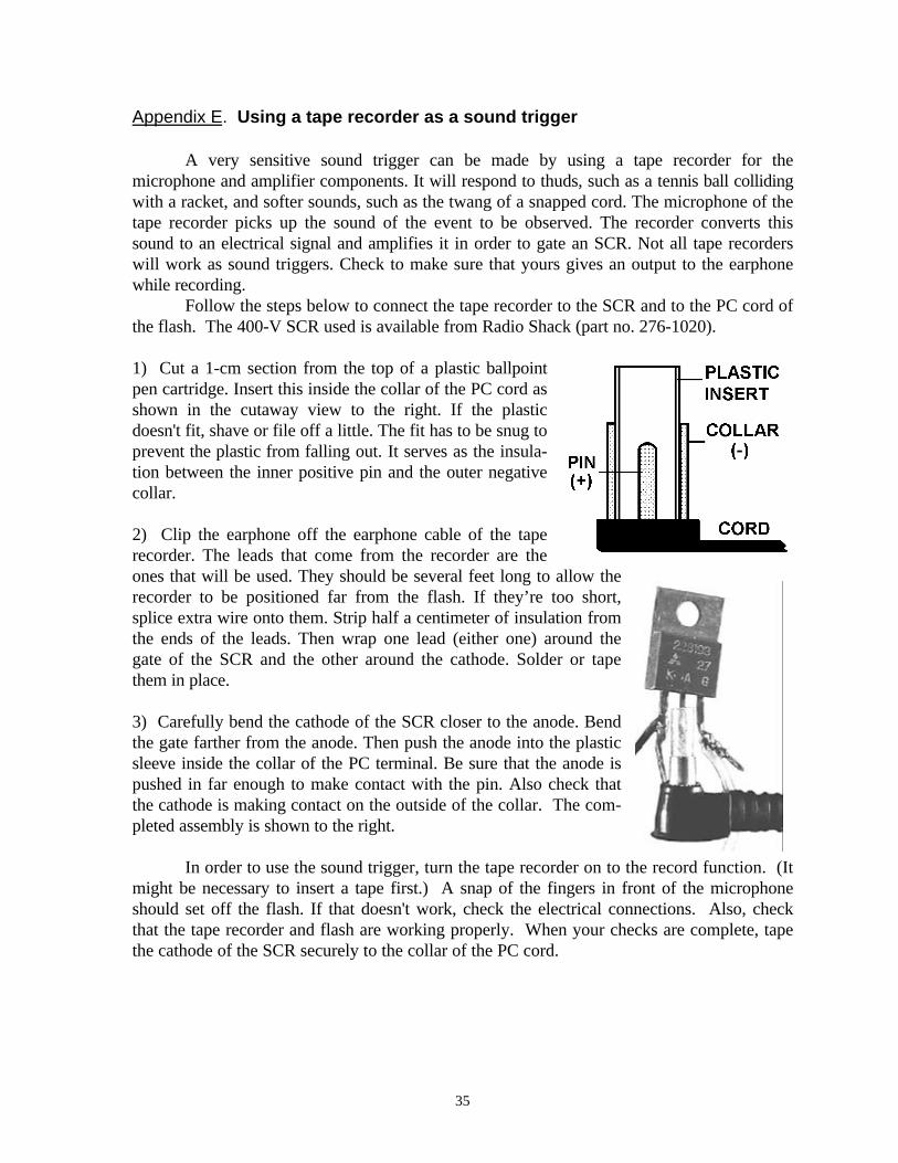
1) Cut a 1-cm section from the top of a plastic ballpointpen cartridge. Insert this inside the collar of the PC cord asshown in the cutaway view to the right. If the plasticdoesn't fit, shave or file off a little. The fit has to be snug toprevent the plastic from falling out. It serves as the insula-tion between the inner positive pin and the outer negativecollar.
2) Clip the earphone off the earphone cable of the taperecorder. The leads that come from the recorder are theones that will be used. They should be several feet long to allow therecorder to be positioned far from the flash. If they’re too short,splice extra wire onto them. Strip half a centimeter of insulation fromthe ends of the leads. Then wrap one lead (either one) around thegate of the SCR and the other around the cathode. Solder or tapethem in place.
3) Carefully bend the cathode of the SCR closer to the anode. Bendthe gate farther from the anode. Then push the anode into the plasticsleeve inside the collar of the PC terminal. Be sure that the anode ispushed in far enough to make contact with the pin. Also check thatthe cathode is making contact on the outside of the collar. The com-pleted assembly is shown to the right.
In order to use the sound trigger, turn the tape recorder on to the record function. (Itmight be necessary to insert a tape first.) A snap of the fingers in front of the microphoneshould set off the flash. If that doesn't work, check the electrical connections. Also, checkthat the tape recorder and flash are working properly. When your checks are complete, tapethe cathode of the SCR securely to the collar of the PC cord.
36
Appendix F. Photogate trigger circuits
Two circuits are described. Each uses an infrared emitter and detector. (A penlightcan provide a substitute for the infrared emitter, even when using an infrared detector.) Thetransistor switch has a very rapid response and is good for triggering on fast-moving objects.The Schmitt trigger works better for slow-moving objects such as a milk drop falling throughthe photogate.
There are many infrared emitters and photodetectors that can be used with thesecircuits. The ones that are given in the parts lists are usually available from Radio Shack.
An interrupter is a device that includes both an emitter and detector in a single,molded-plastic package. An interrupter is useful when the object that breaks the infraredbeam is narrow, since the gap between detector and emitter is only about an eighth of an inch.One possible interrupter that can be used with either circuit is given below.22
A. Transistor switch
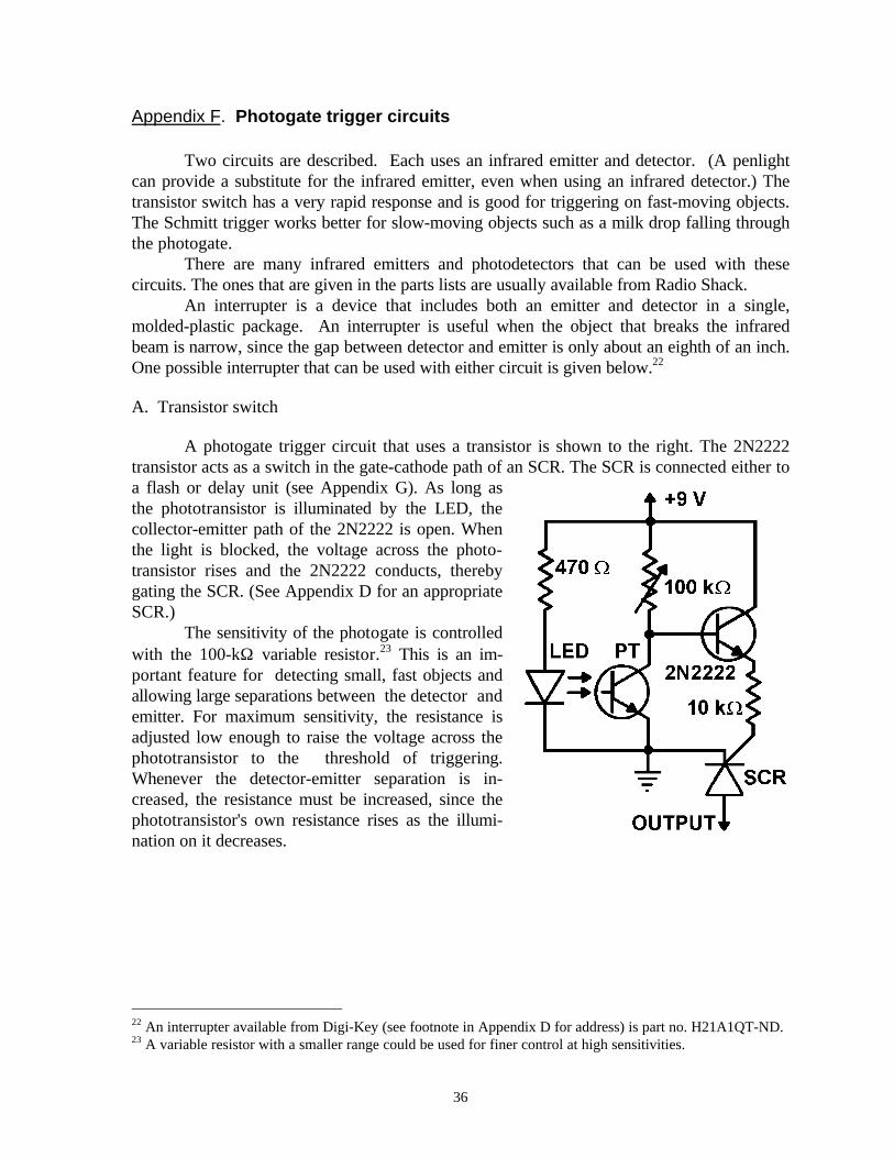
A photogate trigger circuit that uses a transistor is shown to the right. The 2N2222transistor acts as a switch in the gate-cathode path of an SCR. The SCR is connected either toa flash or delay unit (see Appendix G). As long asthe phototransistor is illuminated by the LED, thecollector-emitter path of the 2N2222 is open. Whenthe light is blocked, the voltage across the photo-transistor rises and the 2N2222 conducts, therebygating the SCR. (See Appendix D for an appropriateSCR.)
The sensitivity of the photogate is controlledwith the 100-kΩ variable resistor.23 This is an im-portant feature for detecting small, fast objects andallowing large separations between the detector andemitter. For maximum sensitivity, the resistance isadjusted low enough to raise the voltage across thephototransistor to the threshold of triggering.Whenever the detector-emitter separation is in-creased, the resistance must be increased, since thephototransistor's own resistance rises as the illumi-nation on it decreases.
22 An interrupter available from Digi-Key (see footnote in Appendix D for address) is part no. H21A1QT-ND.23 A variable resistor with a smaller range could be used for finer control at high sensitivities.
37
Parts list for transistor switch
Infrared emitter (XC-880-A) 470-Ω resistorInfrared phototransistor (TIL414) 10-kΩ resistor2N2222 transistor 400-V sensitive gate SCR9-V battery and clip 100-kΩ variable resistor
B. Schmitt trigger
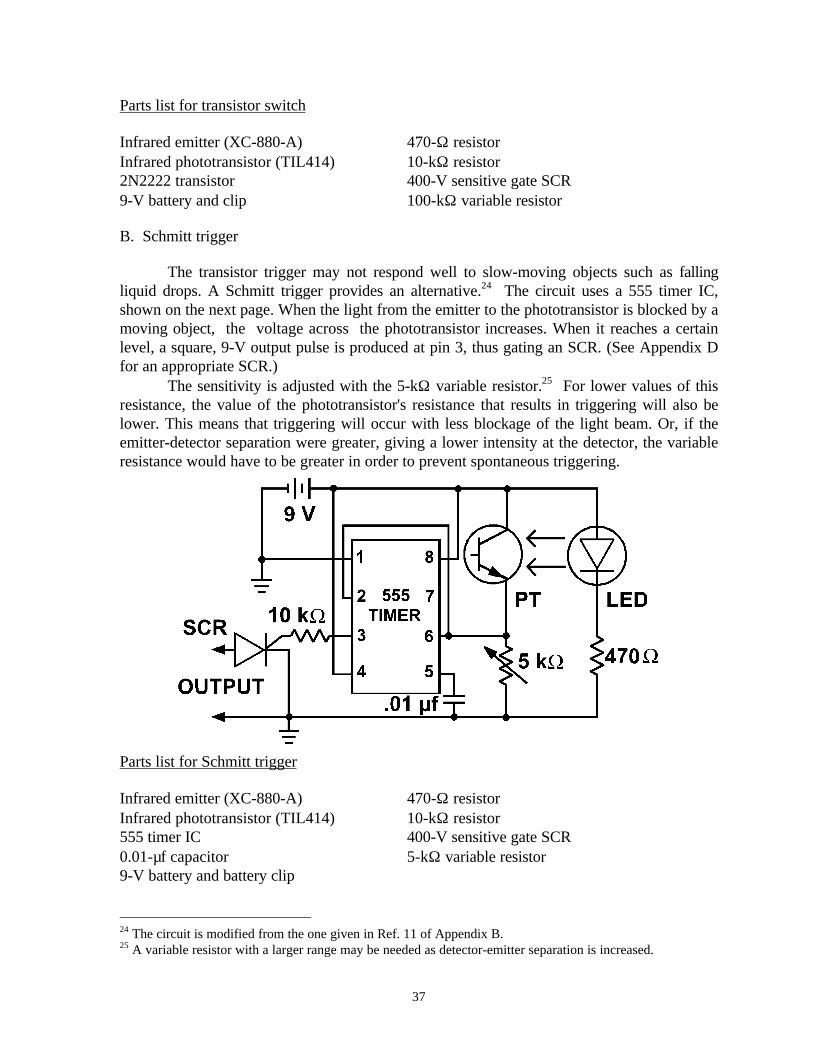
The transistor trigger may not respond well to slow-moving objects such as fallingliquid drops. A Schmitt trigger provides an alternative.24 The circuit uses a 555 timer IC,shown on the next page. When the light from the emitter to the phototransistor is blocked by amoving object, the voltage across the phototransistor increases. When it reaches a certainlevel, a square, 9-V output pulse is produced at pin 3, thus gating an SCR. (See Appendix Dfor an appropriate SCR.)
The sensitivity is adjusted with the 5-kΩ variable resistor.25 For lower values of thisresistance, the value of the phototransistor's resistance that results in triggering will also belower. This means that triggering will occur with less blockage of the light beam. Or, if theemitter-detector separation were greater, giving a lower intensity at the detector, the variableresistance would have to be greater in order to prevent spontaneous triggering.
Parts list for Schmitt trigger
Infrared emitter (XC-880-A) 470-Ω resistorInfrared phototransistor (TIL414) 10-kΩ resistor555 timer IC 400-V sensitive gate SCR0.01-µf capacitor 5-kΩ variable resistor9-V battery and battery clip
24 The circuit is modified from the one given in Ref. 11 of Appendix B.25 A variable resistor with a larger range may be needed as detector-emitter separation is increased.
38
Appendix G. Electronic delay circuit
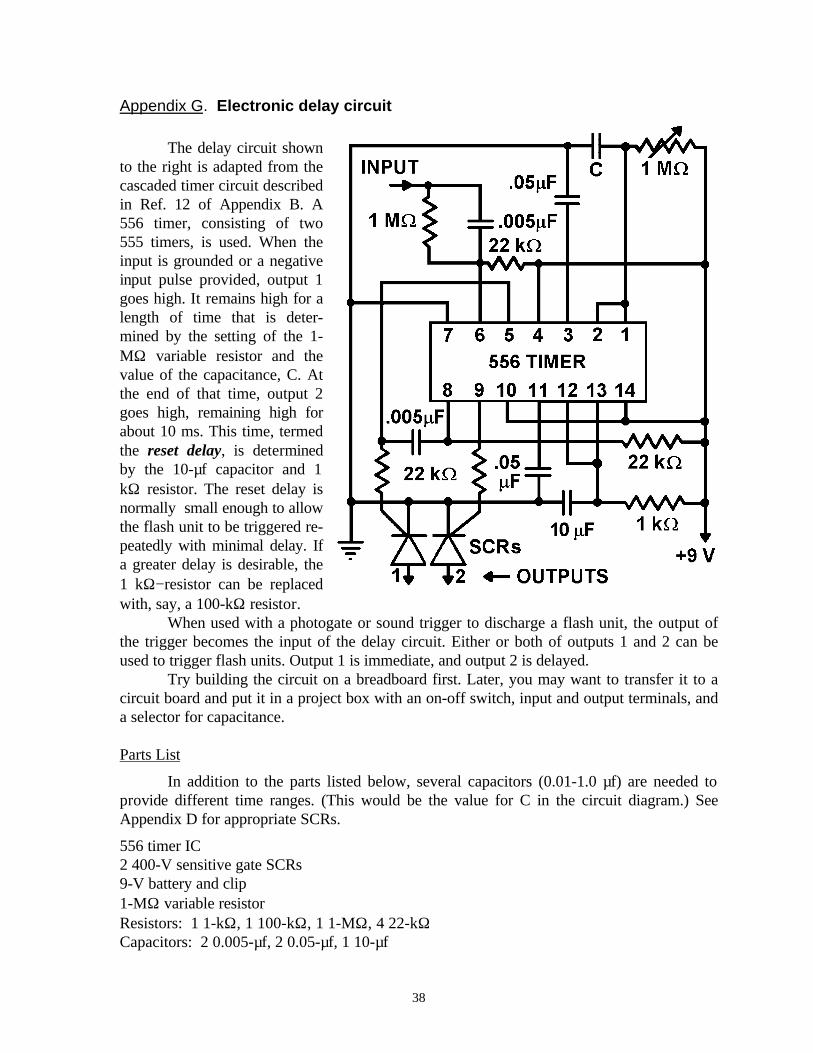
The delay circuit shownto the right is adapted from thecascaded timer circuit describedin Ref. 12 of Appendix B. A556 timer, consisting of two555 timers, is used. When theinput is grounded or a negativeinput pulse provided, output 1goes high. It remains high for alength of time that is deter-mined by the setting of the 1-MΩ variable resistor and thevalue of the capacitance, C. Atthe end of that time, output 2goes high, remaining high forabout 10 ms. This time, termedthe reset delay, is determinedby the 10-µf capacitor and 1kΩ resistor. The reset delay isnormally small enough to allowthe flash unit to be triggered re-peatedly with minimal delay. Ifa greater delay is desirable, the1 kΩ−resistor can be replacedwith, say, a 100-kΩ resistor.
When used with a photogate or sound trigger to discharge a flash unit, the output ofthe trigger becomes the input of the delay circuit. Either or both of outputs 1 and 2 can beused to trigger flash units. Output 1 is immediate, and output 2 is delayed.
Try building the circuit on a breadboard first. Later, you may want to transfer it to acircuit board and put it in a project box with an on-off switch, input and output terminals, anda selector for capacitance.
Parts List
In addition to the parts listed below, several capacitors (0.01-1.0 µf) are needed toprovide different time ranges. (This would be the value for C in the circuit diagram.) SeeAppendix D for appropriate SCRs.
556 timer IC2 400-V sensitive gate SCRs9-V battery and clip1-MΩ variable resistorResistors: 1 1-kΩ, 1 100-kΩ, 1 1-MΩ, 4 22-kΩCapacitors: 2 0.005-µf, 2 0.05-µf, 1 10-µf
39
Appendix H. Making a contact trigger
Here is one way to make a contact trigger. Begin by assembling the following supplies:
2 20-cm squares of stiff cardboard (1-2 mm thick)2 20-cm squares of aluminum foil1 20-cm square of black construction paper or poster boardGlue and tape2 1-m wire leads
Now do the following:
1) Smooth any wrinkles out of a 20-cm square of aluminum foil. Then glue the foil to thesame size stiff cardboard. Tape the bare end of a 1-m wire lead to one corner of the foil.
2) Smooth out another 20-cm square of aluminum foil and glue it to black poster board orconstruction paper of the same size. Tape another 1-m wire lead to a corner of this foil.
3) From a second 20-cm square of stiff cardboard, cut out a 15-cm square hole, leaving asquare frame of 2.5 cm width. Glue this frame onto the foil prepared in step 2).
4) Arrange the various pieces as shown in the diagram below. Notice that the cardboardframe acts as a spacer to separate the pieces of foil. If an object is dropped onto the upperpiece, it will be forced into contact with the lower.
40
Appendix I. Problems in high-speed measurement
Problem 1. High-speed clocks
a. Clocks with rotating hands measure time in terms of the angle swept out by the hand duringthe time interval. Representing the angle as θ and the period of the hand as T, write an equa-tion for the time interval, ∆t, in terms of θ and T.
The photograph to theright shows two rotat-ing discs, A and B.Although each dischas a single hand, twoimages of the hand areseen because the discswere lit by sequentialbursts of light fromtwo flash units. Thefrequency of disc Bwas measured with astroboscope and foundto be 50.5 rotationsper second.
b. Determine the time interval between the bursts of light. Also estimate the uncertainty inyour result, based on the accuracy and precision of your measurement of angle.
c. Determine the period of disc A.
41
Problem 2. Speed of a balloon rip
The figure below shows a double-exposure of a balloon rip taken according to the method ofActivity 17. The frequency of the clock was 51.7 rotations per second, and the diameter of thedisc was 0.105 m.
a. Measure the angle swept out by the clock hand and calculate the time interval between theflashes of light.
b. Measure the diameter of the clock disc on the photograph and calculate a scale factor to beused in converting distances measured on the photograph to actual size.
42
c. Measure the distance between the two images of the rip vertex. Then use the scale factorto convert to actual size.
d. Calculate the speed of the rip.
e. Estimate the uncertainties in your measurements of distance and time. Use them to estimatethe uncertainty in the measurement of speed.