Embed Size (px)
Citation preview

A TRIDENT SCHOLAR PROJECT REPORT
NO. 246
'Design and Construction of a Thermophotovoltaic Energy Conversion System Using Combustion Gases from a T-58 Gas Turbine"
UNITED STATES NAVAL ACADEMY ANNAPOUS, MARYLAND
This document has been approved for public release and sale; its distribution is unlimited.
20031204 007 USNA-1531-2
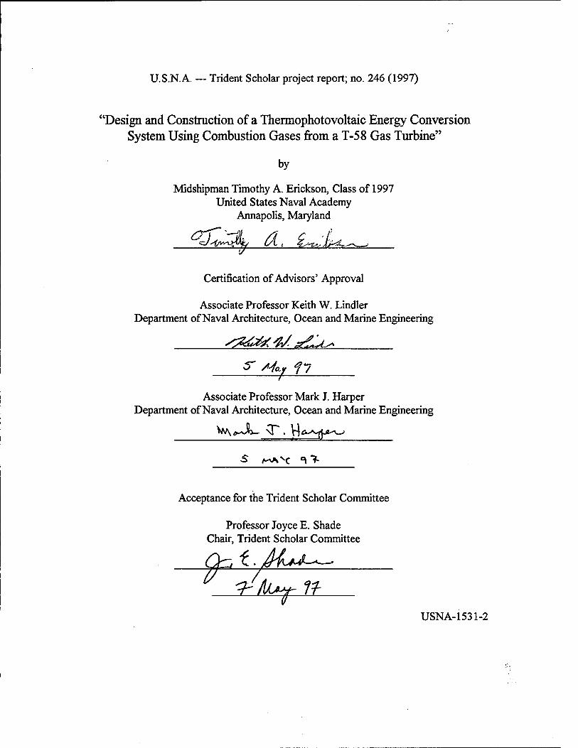
REPORT DOCUMENTATION PAGE. Form Approved 0MB No. 074-0188
Public reporting burden for this collection of information is estimated to average 1 hour per response, including g the time for reviewing instmctions, searching existing data sources, gathering and maintaining the data needed, and completing and reviewing the collection of information. Send comments regarding this burden estimate or any other aspect of the collection of information, including suggestions for reducing this burden to Washington Headquarters Services, Directorate for Information Operations and Reports, 1215 Jefferson Davis Highway, Suite 1204, Arlington, VA 22202-4302, and to the Office of Management and Budget, Paperwork Reduction Project (0704-0188), Washington, DC 20503.
1. AGENCY USE ONLY (Leave blank) 2. REPORT DATE 7 May 1997
3. REPORT TYPE AND DATE COVERED
4. TITLE AND SUBTITLE Design and construction of a thermophotovoltaic energy conversion system using combustion gases from a T-58 gas turbine
5. FUNDING NUMBERS
6. AUTHOR(S) Timothy A. Erickson
7. PERFORMING ORGANIZATION NAIVIE(S) AND ADDRESS(ES)
U.S. Naval Academy Annapolis, MD
8. PERFORMING ORGANIZATION REPORT NUMBER
USNA Trident Scholar project report no. 246 (1997)
9. SPONSORING/MONITORING AGENCY NAME(S) AND ADDRESS(ES) 10. SPONSORING/MONITORING AGENCY REPORT NUMBER
11. SUPPLEMENTARY NOTES Accepted by the U.S. Trident Scholar Committee
12a. DISTRIBUTION/AVAILABILITY STATEMENT This document has been approved for pxiblic release; its distribution is UNLIMITED.
12b. DISTRIBUTION CODE
13. ABSTRACT: An ongoing project at the U.S. Naval Academy involves the development of a prototype ThermoPhotoVoltaic (TPV) generator that uses a General Electric T-58 gas turbine as the heat source. The combustion gas was tapped from the T-58's combustor through em igniter port and then extracted through a silicon carbide composite tube into a ceramic emitter. The emitter was also made from the same silicon carbide composite. The TFV generator was designed to ease removal of the emitter so different materials could be tested at a later date. The ceramic emitter is heated by the combustion gas via convection, and then serves the 'HyV generator by radiating the heat outwards where it can be absorbed by thermophotovoltaic cells and converted directly into electricity. This paper details the design and construction of the TPV generator and gives results of initial tests of the gas tiirbine.
14. SUBJECT TERMS Composite, gas turbine, emitter, thermophotovoltaic
15. NUMBER OF PAGES
16. PRICE CODE
17. SECURITY CLASSIFICATION OF REPORT
18. SECURITY CLASSIFICATION OF THIS PAGE
19. SECURITY CLASSIFICATION OFABSTRACT
20. LIMITATION OF ABSTRACT
NSN 7540-01-280-5500 (Rev.2-89)
Standard Form 298 Prescribed by ANSI Std. Z39-18 298-102
U.S.N.A. -- Trident Scholar project report; no. 246 (1997)
"Design and Construction of a Themiophotovoltaic Energy Conversion System Using Combustion Gases from a T-58 Gas Turbine"
by
Midshipman Timothy A. Erickson, Class of 1997 United States Naval Academy
Annapolis, Maryland
cy^i'v-
Certification of Advisors' Approval
Associate Professor Keith W. Lindler Department of Naval Architecture, Ocean and Marine Engineering
^^^gj^^^'^.g^^
^ y-^y f 7
Associate Professor Mark J. Harper Department of Naval Architecture, Ocean and Marine Engineering
V/A»>Jta— \P. v4<&>\.|^.j-'>>_^
-5 A-AAH '\ "^
Acceptance for the Trident Scholar Committee
Professor Joyce E. Shade Chair, Trident Scholar Committee
-A <hkA^n
USNA-153I-2
ABSTRACT
An ongoing project at the U.S. Naval Academy involves the development of a prototype ThermoPhotoVoltaic (TPV) generator that uses a General Electric T-58 gas turbine as the heat source. The combustion gas was tapped from the T-58's combustor through an ignitor port and then extracted through a silicon carbide composite tube into a ceramic emitter. The emitter was also made from the same silicon carbide composite. The TPV generator was designed to ease removal of the emitter so different materials could be tested at a later date. The ceramic emitter is heated by the combustion gas via convection, and then serves the TPV generator by radiating the heat outwards where it can be absorbed by thermophotovoltaic cells and converted directly into electricity. This paper details the design and construction of the TPV generator and gives results of initial tests of the gas turbine.
KEYWORDS: composite, gas turbine, emitter, thermophotovohaic

TABLE OF CONTENTS ABSTRACT TABLE OF CONTENTS LIST OF FIGURES
1 2 4
1.0 SUMMARY
1.1 OBJECTIVES 1.2 METHODOLOGY
5 6
2.0 BACKGROUND 7
3.0 PHASE I - SUPPORTING RESEARCH 9
3.1 EMITTER 9 3.2 TPV CELLS AND THE PHOTOELECTRIC EFFECT 11 3.3 CERAMICS 14 3.4 CERAMIC COMPOSITES 15 3.5 COMBUSTORLAYOUT 16 3.6 TEMPERATURE PROFILE EXPERIMENT 17
4.0 PHASE II - SYSTEM DESIGN 27
4.1 INTIAL PARAMETERS 4.2 MOUNTING SYSTEM 4.3 THREADED ROD 4.4 LOWER STEEL PLATE 4.5 CERAMIC BLOCK 4.6 EXTRACTION TUBE 4.7 UPPER STEEL PLATE 4.8 GAS TUBE 4.9 EMITTER 4.10 COOLING MODULE 4.11 STEEL END CAP 4.12 CERAMIC END CAP 4.13 SPRINGS
27 29 31 32 33 37 39 40 42 43 45 46 47

5.0 PHASE III - FINAL DESIGN 49
5.1 ASSEMBLY OF TPV GENERATOR 49 5.2 PLAN DRAWINGS FOR INDIVIDUAL COMPONENTS 62
6.0 CONCLUSIONS 70
6.1 PROJECT RESULTS 70 6.2 CONCLUSIONS 70
REFERENCES 72
APPENDICES 75
A. ANALYSIS OF GAS FLOW EFFECTS 76 B. MATERIALS TEST: OMEGATITE450 82 C. RADIATION SHAPE FACTORS 86
LIST OF FIGURES
HGUREl. PHOTOVOLTAIC CELL 7 nGUEE2. PLANCK'S LAW 10 FIGURES. THERMOPHOTOVOLTAIC CELL 12 FIGURE 4. COMBUSTOR LAYOUT 16 HGURES. PHASE I PROBE DESIGN 19 FIGURE 6. THERMOCOUPLE PROBE DEPTH 21 nGURET PHASED PROBE DESIGN 21 nGURE8. T-58 TEMPERATURE PROFILE 26 FIGURE 9. PRELIMINARY GENERATOR DESIGN 28 FIGURE 10. FRONT MOUNTING BRACKETS 29 FIGURE 11. MOUNTING PLATE 30 nOURE 12. MOUNTING PLATE INSTALLATION 31 HGURE 13. THREADED ROD AND NUT 31 HGURE 14. THREADED ROD INSTALLATION 32 nGURE 15. LOWER STEEL PLATE 33 FIGURE 16. CERAMIC BLOCK 35 HGURE 17. EXTRACTION TUBE INSTALLATION 37 HGURE 18. ALUMINA GASKETS 39 HGURE 19. IGNITOR AND CERAMIC COLLAR 39 FIGURE 20. UPPER STEEL PLATE 40 HGURE 21. EXTRACTION/GAS TUBE 40 HGURE 22. EMITTER/GAS TUBE INSTALLATION 42 HGURE 23. EMmER 43 HGURE 24. COOLING MODULE (PROFILE AND CROSS SECTION) 44 HGURE 25. STEEL END CAP 45 FIGURE 26. CERAMIC END CAP 46 HGURE 27. CERAMIC AND STEEL END CAP 47 HGURE 28. INSTALLATION-MOUNTING PLATETBRACKETS 50 FIGURE 29. INSTALLATION-THREADED RODS 51 HGURE 30. INSTALLAHON-LOWER STEEL PLATE 52 HGURE 31. INSTALLATION-CERAMIC BLOCK 53 HGURE 32. INSTALLATION-UPPER STEEL PLATE 54 FIGURE 33. INSTALLATION-COOLING MODULE 55 FIGURE 34. BSrSTALLATION-EMirTER 56 HGURE 35. INSTALLATION-END CAP 57 HGURE 36. INSTALLATION-SPRINGS 58 HGURE 37. INSTALLATION-WASHERS 59 HGURE 38. INSTALLATION-DIMENSIONS 60 HGURE 39. INSTALLATION COMPLETE 61 HGURE 40. MOUNTING PLATE (TOP) 62 HGURE 41. FORWARD MOUNTING BRACiCETS 63 HGURE 42. AFT MOUNTING BRACKETS 64 HGURE 43. THREADED ROD AND WASHER 65 HGURE 44. STEEL COMPONENTS 66 HGURE 45. CERAMIC COMPONENTS 67 HGURE 46. EMirTER AND GAS TUBE 68 HGURE 47. COOLING MODULE PLANS 69 FIGURE 48. CROSS SECTION OF T-58 COMBUSTOR SECTION 76 HGURE 49. MAXIMUM EXTRACTION TUBE DIMENSIONS 77 HGURE 50. FORCE DIAGRAM FOR EXTRACTION TUBE 81 HGURE 51. EXTRACTION TUBE PROTOTYPE 83 HGURE 52. SHAPE FACTOR (FOIL) 86 HGURE 53. SHAPE FACTOR (CELL) 87

1.0 SUMMARY
The scope of this project involves the development of a thermophotovoltaic generator using a T-58 gas turbine engine as a heat source, including documentation of completed work and research.
1.1 OBJECTIVES
The sponsors of the project dictated that a working thermophotovohaic power generation demonstration unit be completed which meets the following guidelines:
1. Use high temperature gas from a T-58 gas turbine as the heat source 2. Be self-contained and mounted to the T-58 3. Use cooling water to maintain cell temperature 4. Automatically shut off in event of cooling failure 5. Produce 100 watts electricity
forth: In addition to the design guidelines, the following research directives were set
1. Determine the radial temperature profile of the T-58 combustor 2. Assess material suitability and selection 3. Explore use of Labview "virtual instrument" control panel programming 4. Conduct force analysis of gas flow on the tube inside the combustor
1.2 METHODOLOGY
In accordance with Section 1.1, the objectives and directives of the project were completed through the following design approach:
Phase I: Supporting Research For Phase I, a literature review was conducted to include the applicable material concepts, theory of photovoltaic operation, and necessary heat transfer equations and design considerations.
Phase II: Svstem Design Structural computations and physical size constraints and requirements were defined and used to make schematic drawings. Materials selection and testing was carried out in the U.S. Naval Academy technical support shop.
Phase ni: Final Design The design was refined based on prior evaluation and testing. Further refinements were made to compensate for fabrication constraints.
2.0 BACKGROUND
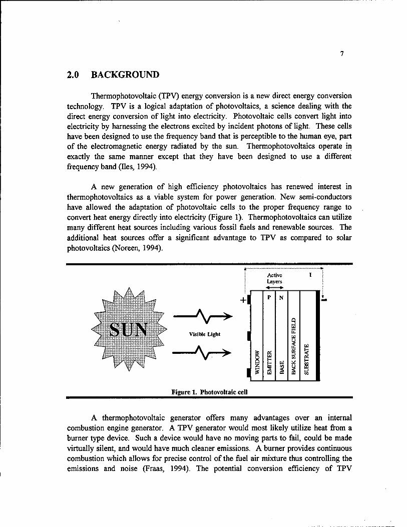
Thermophotovoltaic (TPV) energy conversion is a new direct energy conversion technology. TPV is a logical adaptation of photovoltaics, a science dealing with the direct energy conversion of light into electricity. Photovoltaic cells convert light into electricity by harnessing the electrons excited by incident photons of light. These cells have been designed to use the frequency band that is perceptible to the human eye, part of the electromagnetic energy radiated by the sun. Thermophotovoltaics operate in exactly the same manner except that they have been designed to use a different frequency band (lies, 1994).
A new generation of high efficiency photovoltaics has renewed interest in thermophotovoltaics as a viable system for power generation. New semi-conductors have allowed the adaptation of photovoltaic cells to the proper frequency range to convert heat energy directly into electricity (Figure 1). Thermophotovoltaics can utilize many different heat sources including various fossil fuels and renewable sources. The additional heat sources offer a significant advantage to TPV as compared to solar photovoltaics (Noreen, 1994).
A^ Visible Li^t
Ar^ I
I
Active Layers
w
U3
Figure 1. Photovoltaic cell
A thermophotovoltaic generator offers many advantages over an internal combustion engine generator. A TPV generator would most likely utilize heat from a burner type device. Such a device would have no moving parts to fail, could be made virtually silent, and would have much cleaner emissions. A burner provides continuous combustion which allows for precise control of the fuel air mixture thus controlling the emissions and noise (Fraas, 1994). The potential conversion efficiency of TPV

generators is increasing with research and already exceeds that for the competing direct energy conversion technologies of thermionics and thermoelectrics. Thermophotovoltaics offer an order of magnitude greater power densities than fiiel cells (Krist, 1994).
It has been proposed that thermophotovoltaics be used in many varied applications. They would be excellent for remote electrical generators, especially in areas with natural gas or oil pipelines and no electrical service. Thermophotovohaics can also be used for co-generation in large power plants, by using heat energy rejected to the exhaust. Thermophotovoltaics could enable gas-powered appliances to be run independently of the electrical grid that normally powers the ignition and control systems. TPV would also be very effective for a hybrid electric vehicle and could replace a small internal combustion engine with a cleaner continuous burner. Some of this technology already exists. TPV power generation can draw on existing technology such as radiant burners used for paint drying, advanced high temperature gas turbines, high temperature heat exchangers, and solar photovoltaic concentrators (Noreen, 1994).
3.0 PHASE I - SUPPORTING RESEARCH
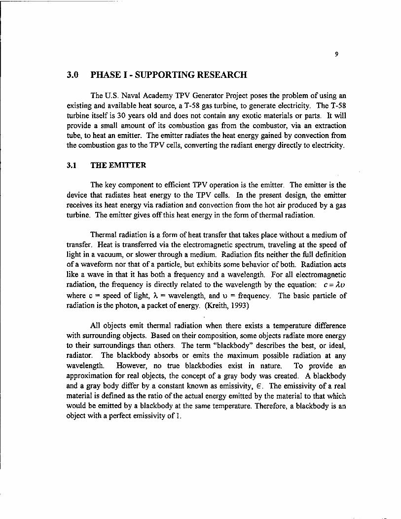
The U.S. Naval Academy TPV Generator Project poses the problem of using an existing and available heat source, a T-58 gas turbine, to generate electricity. The T-58 turbine itself is 30 years old and does not contain any exotic materials or parts. It will provide a small amount of its combustion gas from the combustor, via an extraction tube, to heat an emitter. The emitter radiates the heat energy gained by convection from the combustion gas to the TPV cells, converting the radiant energy directly to electricity.
3.1 THE EMITTER
The key component to efficient TPV operation is the emitter. The emitter is the device that radiates heat energy to the TPV cells. In the present design, the emitter receives its heat energy via radiation and convection from the hot air produced by a gas turbine. The emitter gives off this heat energy in the form of thermal radiation.
Thermal radiation is a form of heat transfer that takes place without a medium of transfer. Heat is transferred via the electromagnetic spectrum, traveling at the speed of light in a vacuum, or slower through a medium. Radiation fits neither the full definition of a waveform nor that of a particle, but exhibits some behavior of both. Radiation acts like a wave in that it has both a frequency and a wavelength. For all electromagnetic radiation, the frequency is directly related to the wavelength by the equation: c = Zo where c = speed of light, X = wavelength, and u = frequency. The basic particle of radiation is the photon, a packet of energy. (Kreith, 1993)
All objects emit thermal radiation when there exists a temperature difference with surrounding objects. Based on their composition, some objects radiate more energy to their surroundings than others. The term "blackbody" describes the best, or ideal, radiator. The blackbody absorbs or emits the maximum possible radiation at any wavelength. However, no true blackbodies exist in nature. To provide an approximation for real objects, the concept of a gray body was created. A blackbody and a gray body differ by a constant known as emissivity, 6. The emissivity of a real material is defined as the ratio of the actual energy emitted by the material to that which would be emitted by a blackbody at the same temperature. Therefore, a blackbody is an object with a perfect emissivity of 1.
10
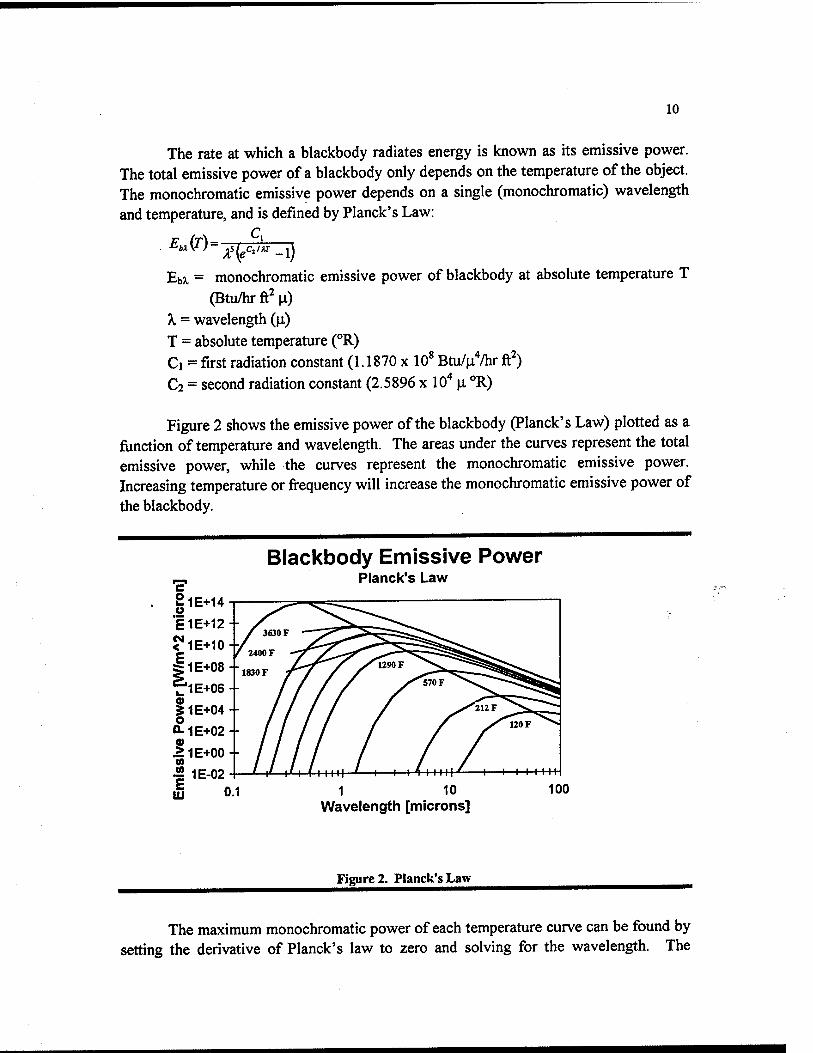
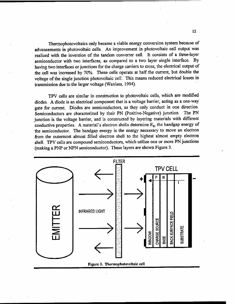
The rate at which a blackbody radiates energy is known as its emissive power. The total emissive power of a blackbody only depends on the temperature of the object. The monochromatic emissive power depends on a single (monochromatic) wavelength and temperature, and is defined by Planck's Law:
Eb^ = monochromatic emissive power of blackbody at absolute temperature T (Btu/hr ft^ \i)
X = wavelength (\i) T = absolute temperature (°R) Ci = first radiation constant (1.1870 x 10* Btu/\i%T ft^) C2 = second radiation constant (2.5896 x lO'* \x °R)
Figure 2 shows the emissive power of the blackbody (Planck's Law) plotted as a function of temperature and wavelength. The areas under the curves represent the total emissive power, while the curves represent the monochromatic emissive power. Increasing temperature or frequency will increase the monochromatic emissive power of the blackbody.
|lE+14
I1E+12--
<'lE+10+,
ilE+08 +
f'lE+oe
51E+04
Q-1E+02 9* >1E+00-- w I 1E-02 II 0.1
Blackbody Emissive Power Planck's Law
1 10 Wavelength [microns]
Figure 2. Planck's Law
The maximum monochromatic power of each temperature curve can be found by setting the derivative of Planck's law to zero and solving for the wavelength. The
11
resulting relation is known as Wein's Displacement law, given by the equation ^axT = 5216.4(i°R. This equation corresponds to the diagonal line in Figure 2.
The total emissive power of a blackbody is found by the summation of all monochromatic emissive powers. Integration yields the Stefan-Boltzmann law:
£j, (r) = (JT* where Eb = total emissive power (Btu/hr ft^)
T = absolute temperature (°R) a = Stefan-Boltzmann Constant
0.1714 X 10'* Btu/hr ft^°R^ The Stefan-Boltzmann law shows that the emissive power is proportional to the fourth power of the temperature. Therefore, increasing temperature will significantly increase the radiation emitted by a blackbody.
In order to achieve high power density, it is necessary for the emitter material to have as high an emissivity as possible. Besides high emissivity, the emitter must withstand high temperatures. At the temperatures necessary for a TPV generator, the melting or sublimation of the emitter material is of concern (Noreen, 1994). The material has to be strong to withstand loading from thermal expansion. The material must also have a low thermal mass in order to speed heat up and cool down. The thermal mass will dictate the amount of damage done to the system in the event of a cooling system failure. A low thermal mass ensures rapid heat dissipation to the air by convection, thereby avoiding exposure of the cells to high temperatures for extended periods.
The operating temperature of the emitter is of great importance. The emitter material's durability at high temperature will determine the upper operating temperature limit. By the nature of their construction, TPV cells are most efficient converting radiant energy at a particular wavelength. This wavelength is a function of the semiconductor materials that compose TPV cells. As Wien's displacement law predicts, the peak frequency of the radiated light from the emitter is dependent on the surface temperature of the emitter (Krieth, 1993). To maximize the efficiency of the TPV generator, it is necessary to select the emitter temperature such that the energy is radiated at the particular wavelength efficiently converted by the TPV cells.
3.2 TPV CELLS AND THE PHOTOELECTRIC EFFECT
Thermophotovoltaic cells are responsible for the actual electrical power generation inside the TPV generator. TPV cells convert the radiant energy from the emitter directly into electricity using the photoelectric effect.
12
Thermophotovoltaics only became a viable energy conversion system because of advancements in photovoltaic cells. An improvement in photovoltaic cell output was realized with the invention of the tandem converter cell. It consists of a three-layer semiconductor with two interfaces, as compared to a two layer single interface. By having two interfaces or junctions for the charge carriers to cross, the electrical output of the cell was increased by 70%. These cells operate at half the current, but double the voltage of the single junction photovoltaic cell. This means reduced electrical losses in transmission due to the larger voltage (Wanlass, 1994).
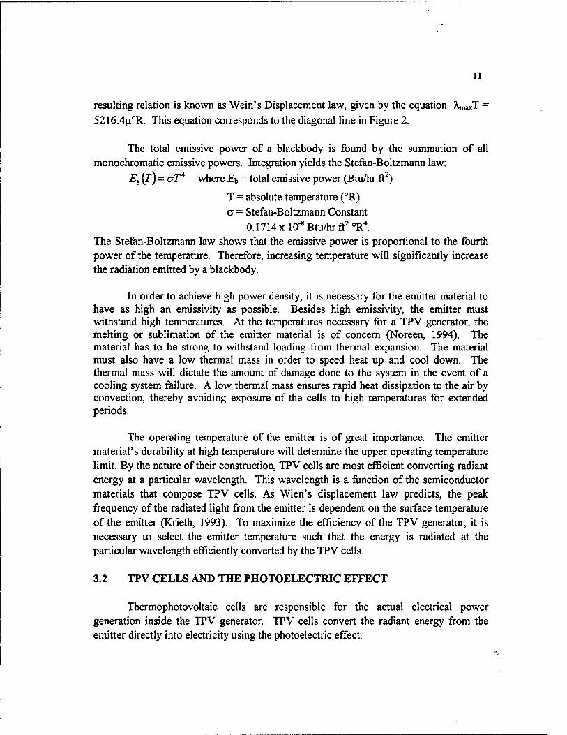
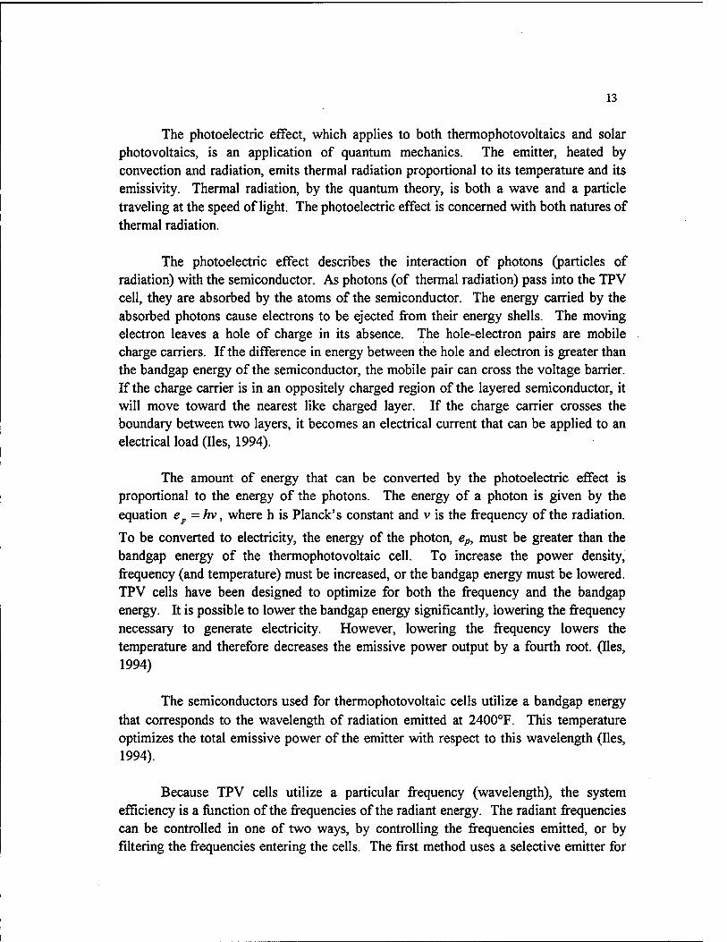
TPV cells are similar in construction to photovoltaic cells, which are modified diodes. A diode is an electrical component that is a vohage barrier, acting as a one-way gate for current. Diodes are semiconductors, as they only conduct in one direction. Semiconductors are characterized by their PN (Positive-Negative) junction. The PN junction is the vohage barrier, and is constructed by layering materials with different conductive properties. A material's electron shells determine Eg, the bandgap energy of the semiconductor. The bandgap energy is the energy necessary to move an electron from the outermost almost filled electron shell to the highest almost empty electron shell. TPV cells are compound semiconductors, which utilize one or more PN junctions (making a PNP or NPN semiconductor). These layers are shown Figure 3.
TPV CELL
u p N 1
1 m o
s IXI LL. UJ o
_j <c III o u- t- CO oa 5 < UJ =5 oz o O to fc r^ rr LU i^ CO
1 WIN
CO OQ => CO
Figure 3. Thermophotovoltaic cell
13
The photoelectric effect, which applies to both thermophotovoltaics and solar photovoltaics, is an application of quantum mechanics. The emitter, heated by convection and radiation, emits thermal radiation proportional to its temperature and its emissivity. Thermal radiation, by the quantum theory, is both a wave and a particle traveling at the speed of light. The photoelectric effect is concerned with both natures of thermal radiation.
The photoelectric effect describes the interaction of photons (particles of radiation) with the semiconductor. As photons (of thermal radiation) pass into the TPV cell, they are absorbed by the atoms of the semiconductor. The energy carried by the absorbed photons cause electrons to be ejected from their energy shells. The moving electron leaves a hole of charge in its absence. The hole-electron pairs are mobile charge carriers. If the difference in energy between the hole and electron is greater than the bandgap energy of the semiconductor, the mobile pair can cross the voltage barrier. If the charge carrier is in an oppositely charged region of the layered semiconductor, it will move toward the nearest like charged layer. If the charge carrier crosses the boundary between two layers, it becomes an electrical current that can be applied to an electrical load (lies, 1994).
The amount of energy that can be converted by the photoelectric effect is proportional to the energy of the photons. The energy of a photon is given by the equation e^ =hv, where h is Planck's constant and v is the frequency of the radiation.
To be converted to electricity, the energy of the photon, ep, must be greater than the bandgap energy of the thermophotovoltaic cell. To increase the power density, frequency (and temperature) must be increased, or the bandgap energy must be lowered. TPV cells have been designed to optimize for both the frequency and the bandgap energy. It is possible to lower the bandgap energy significantly, lowering the frequency necessary to generate electricity. However, lowering the frequency lowers the temperature and therefore decreases the emissive power output by a fourth root. (lies, 1994)
The semiconductors used for thermophotovoltaic cells utilize a bandgap energy that corresponds to the wavelength of radiation emitted at 2400°F. This temperature optimizes the total emissive power of the emitter with respect to this wavelength (lies, 1994).
Because TPV cells utilize a particular frequency (wavelength), the system efficiency is a function of the frequencies of the radiant energy. The radiant frequencies can be controlled in one of two ways, by controlling the frequencies emitted, or by filtering the frequencies entering the cells. The first method uses a selective emitter for
14
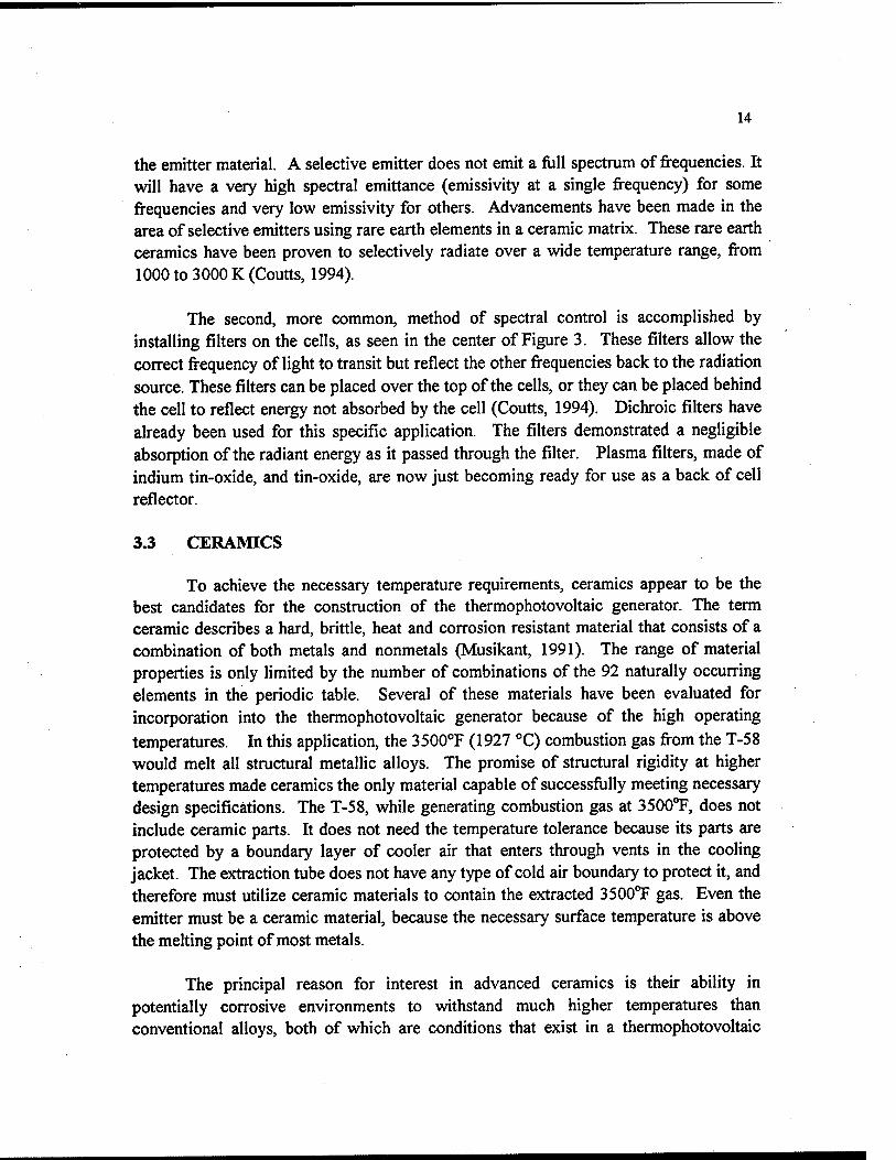
the emitter material. A selective emitter does not emit a fiill spectrum of frequencies. It will have a very high spectral emittance (emissivity at a single frequency) for some frequencies and very low emissivity for others. Advancements have been made in the area of selective emitters using rare earth elements in a ceramic matrix. These rare earth ceramics have been proven to selectively radiate over a wide temperature range, from 1000 to 3000 K (Coutts, 1994).
The second, more common, method of spectral control is accomplished by installing filters on the cells, as seen in the center of Figure 3. These filters allow the correct frequency of light to transit but reflect the other frequencies back to the radiation source. These filters can be placed over the top of the cells, or they can be placed behind the cell to reflect energy not absorbed by the cell (Coutts, 1994). Dichroic filters have already been used for this specific application. The filters demonstrated a negligible absorption of the radiant energy as it passed through the filter. Plasma fihers, made of indium tin-oxide, and tin-oxide, are now just becoming ready for use as a back of cell reflector.
3.3 CERAMICS
To achieve the necessary temperature requirements, ceramics appear to be the best candidates for the construction of the thermophotovoltaic generator. The term ceramic describes a hard, brittle, heat and corrosion resistant material that consists of a combination of both metals and nonmetals (Musikant, 1991). The range of material properties is only limited by the number of combinations of the 92 naturally occurring elements in the periodic table. Several of these materials have been evaluated for incorporation into the thermophotovoltaic generator because of the high operating temperatures. In this application, the 3500°F (1927 °C) combustion gas from the T-58 would melt all structural metallic alloys. The promise of structural rigidity at higher temperatures made ceramics the only material capable of successfijlly meeting necessary design specifications. The T-58, while generating combustion gas at 3500TF, does not include ceramic parts. It does not need the temperature tolerance because its parts are protected by a boundary layer of cooler air that enters through vents in the cooling jacket. The extraction tube does not have any type of cold air boundary to protect it, and therefore must utilize ceramic materials to contain the extracted 3500TF gas. Even the emitter must be a ceramic material, because the necessary surface temperature is above the melting point of most metals.
The principal reason for interest in advanced ceramics is their ability in potentially corrosive environments to withstand much higher temperatures than conventional alloys, both of which are conditions that exist in a thermophotovoltaic

15
generator. However, these excellent properties do not come without a penalty, as flaw sensitivity is the trademark of ceramics (Musikant, 1991). These flaws were explicitly seen in the alumina product Omegatite (Appendix A). lonically bonded molecules typify ceramic materials. The nature of this bond forms a material that is very strong, but also very hard (Smith, 1993). The material has no ductility and is therefore extremely brittle. The characteristics of the ionic bond, in conjunction with flaws already present, make for a very brittle material. This is not suitable for components subject to mechanical stress and thermal shock.
In temperature ranges where common alloys would meU or evaporate, ceramics offer the advantage of high temperature stability as long as the temperature remains fairly constant. However, to be useflil, ceramics must be able to withstand the thermal shock of events like engine ignition, flame out, or temperature excursions that could lead to catastrophic failure of components. To decrease the danger of catastrophic failure of a component due to thermal shock, a ceramic with a low thermal expansion coefficient should be selected (Larsen, 1985). The thermal gradient across the wall thickness of the component is the cause of the shock. The shock will be minimized if the magnitude of the expansion is similar from one wall section to the next. A large thermal expansion coefficient would cause dislocations between parallel planes in the crystal structure, leading to unwanted crack propagation. Crack propagation under tensile stress causes the brittle fi-acture of the ceramic material.
The inherent flaws of a ceramic make it more susceptible to cracking. These " flaws act as a starting point for crack propagation. The number, size, and location of these flaws directly affect the point at which the material will brittle fi-acture. Improved manufacturing techniques would raise the quality of the products and increase their resistance to brittle fracture. It is currently necessary to perform a nondestructive evaluation of a ceramic's properties. Each piece must be sampled to ensure that the properties of the ceramic are consistent. A statistical analysis is performed for the scatter in properties between samples (Musikant, 1991). The variance is documented along with the quantitative properties of the sample.
3.4 CERAMIC COMPOSITES
The primary method of improving ceramic materials is the use of composites. A composite is an artificially created material with two or more separate phases combined during the manufacturing stage of the material. Compositization works by introducing structural materials into a ceramic matrix (Trefilov, 1995). Fine fibrous materials, called whiskers, are added to the ceramic to make up a fourth of the total volume. The incorporation of additional materials stops the microcracking that leads to premature
16
fracture. The additional material is an interruption in the crystalline structure through which the cracks cannot pass (Musikant, 1991). The cracks traversing perpendicular to a whisker must pull the whisker out of the matrix and break the molecular bonds that hold the whisker in place (Trefilov, 1995).
3.5 COMBUSTOR LAYOUT
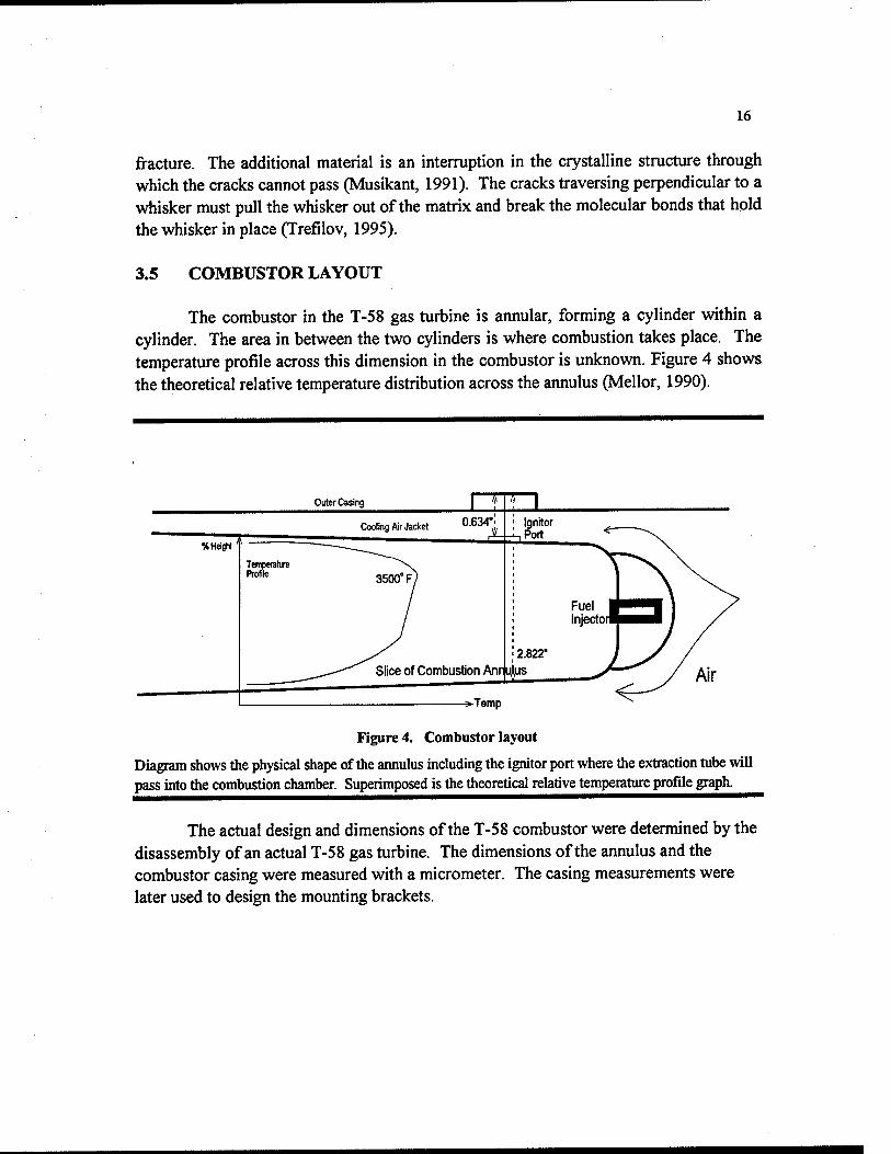
The combustor in the T-58 gas turbine is annular, forming a cylinder within a cylinder. The area in between the two cylinders is where combustion takes place. The temperature profile across this dimension in the combustor is unknown. Figure 4 shows the theoretical relative temperature distribution across the annulus (Mellor, 1990).
Outer Casing
Cooling Air Jacket 0.634' Ignitor .Port
2.822'
Slice of Combustion Anrijijkjs^
-^Temp
Figure 4. Combustor layout
Diagram shows the physical shape of the annulus including the ignitor port where the extraction tube will pass into the combustion chamber. Superimposed is the theoretical relative temperature profile graph.
The actual design and dimensions of the T-58 combustor were determined by the disassembly of an actual T-58 gas turbine. The dimensions of the annulus and the combustor casing were measured with a micrometer. The casing measurements were later used to design the mounting brackets.

17
3.6 TEMPERATURE PROFILE EXPERIMENT
PURPOSE:
The purpose of the experiment was to ascertain the temperature profile across the combustor of the T-58 gas turbine engine. The temperature profile had never been recorded and is otherwise unavailable. The temperature profile is necessary in order to choose the best depth inside the combustor to place the gas extraction tube for the thermophotovoltaic generator.
CONSIDERATIONS:
The estimated temperature for the combustor gases is SSOO'T'; however, the temperature profile inside the combustion chamber has never been measured. This experiment should verify this number and approximate the distance fi^om the outer wall to this point.
Because the estimated temperature of the combustor gases is beyond the melting temperature for most metals, special materials and implements were used to complete the experiment. Because of the temperature requirements, a type C thermocouple (Tungsten, Rhenium) was selected. However, this thermocouple is not designed to operate in an oxidizing environment. Therefore, these thermocouples were used for limited periods and fi^equently changed out because they oxidized when exposed to the flame.
The thermocouples themselves consist only of the two metals in thin wires welded together at a point. These wires do not have any structural properties of their own, and need a structural support. The same problem of temperature applies to most structural materials as well. The choice of structural support is very important, as the material must not melt or decompose at high temperatures, nor fi-acture fi^om the stress of gas flowing over it. Most importantly, it must be resistant to thermal shock. During turbine start-up, the temperature will increase fi-om room temperature to operating temperature in a matter of seconds. The same company that manufactures the type C thermocouples also manufactures an aluminum oxide thermocouple sheath. These sheaths have a product name of Omegatite 450, and were given thermal shock tests using an oxy-acetylene torch (see Appendix B). The thin thermocouple sheaths were the only pieces that did not exhibit any ill effects fi-om the test.
Another concern with the thermocouple sheaths is stress induced by the flow of combustion gas. The force fi^om the flow of combustion gas was calculated for the
18
extraction tube, which is 4 times the diameter of the sheath (Appendix A). Using this force, which is obviously well above what would be expected for the much smaller sheath, the stress was calculated and found to be much lower than the yield strength for the material. The strength of the Omegatite was proven sufficient to vwthstand the combustor gas flow.
TEMPERATURE PROFILE TEST: PHASE ONE
Before measurements could be taken, a method for insertion of the thermocouple into the combustor was found. The turbine ignitor was hollowed out with a drill and the thermocouple sheath was inserted through this piece. The ignitor was sealed to prevent combustion gases from leaving the turbine, while at the same time it facilitated movement of the thermocouple up or down in the combustor.
A thermocouple probe was fabricated by mounting the sheath inside a piece of metal that could be screwed into the ignitor. The sheath would be press fit into the metal collar to form a gas tight seal; the threads on the collar formed a gas tight seal between the collar and the walls of the ignitor. Stainless steel was chosen for the collar because of its non-corrosive properties. Temperature was not a concern for this component, as it would be located in the cooling air jacket. Thermal conduction through the sheath was not a concern either. In thermal shock testing it was found that the Omegatite 450 material did not conduct heat well, as demonstrated by the ability of Midshipman Erickson to hold one end with unprotected skin, while the other end was glowing white hot.
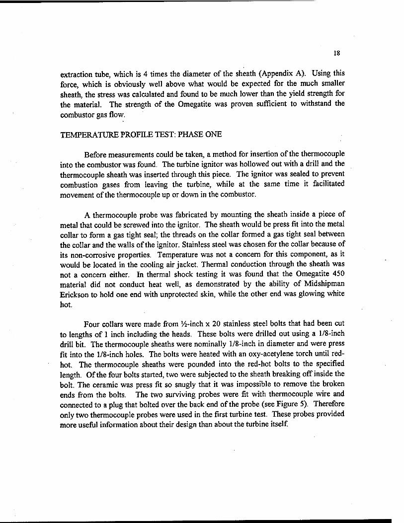
Four collars were made from '/2-inch x 20 stainless steel bolts that had been cut to lengths of 1 inch including the heads. These bohs were drilled out using a 1/8-inch drill bit. The thermocouple sheaths were nominally 1/8-inch in diameter and were press fit into the 1/8-inch holes. The bolts were heated with an oxy-acetylene torch until red- hot. The thermocouple sheaths were pounded into the red-hot bolts to the specified length. Of the four bolts started, two were subjected to the sheath breaking off inside the bolt. The ceramic was press fit so snugly that it was impossible to remove the broken ends from the bohs. The two surviving probes were fit with thermocouple wire and connected to a plug that bolted over the back end of the probe (see Figure 5). Therefore only two thermocouple probes were used in the first turbine test. These probes provided more usefiil information about their design than about the turbine itself
19
(ID 1 jd_ CXneoxttAHTriemioeeuiWSheati |9
1 <I5 . ,_ , U '
Figure 5. Phase I Probe Design
DATA COLLECTION:
During this first test (15 JAN 97), the longer of the two probes was inserted into the combustor and the combustor was started. The engine itself was quickly cycled, for fear of the loss of the probe, which could cause severe foreign object damage to the engine itself The probe was removed and inspected. The tip had carbon buildup, but no other signs of wear. The decision was made to try the second probe, as the safety of installing such a device was now proven. The back portion (past the seal) broke during threading into the ignitor. The break in the thermocouple sheath allowed gases from the combustor to flow out through the tiny holes where the thermocouple wire resides. These two small jets of hot gas could be seen from the control room, but caused no damage to the equipment. Carbon buildup was also found on the tip of the probe and also appeared around the holes where the gases escaped.
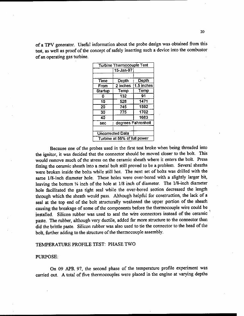
The following data were collected from the first test of the T-58 gas turbine. This data was taken manually using an Omega DP-81T thermocouple reader. This device was calibrated using an Electronic Development Corporation DC Voltage Standard millivolt power supply. The Omega DP-81T requires a 54mV source to calibrate, while the individual thermocouples were calibrated using an ice water bath at 32°F. The thermocouples were accurate to ± 2°F. This data remains unconnected. The raw data must be corrected for the self-emittance of thermal energy from the thermocouple itself as its temperature increases. This occurs because the thermocouple is much hotter than the combustor's walls, which are being cooled by the cooling air. This is known to be the case because the 2-inch probe struck the side of the combustor, and read temperatures in the range of 700 to 800°F. The 1.5-inch probe read temperatures in the region of 1700°F, over twice that of the walls. Because the corrections to the data have not been made, these values are only relative temperatures. The 1000°F relative temperature difference will certainly cause the thermocouple to radiate to the walls. Because of the depth of these probes in the combustor, the data collected was not further analyzed, as it will not yield information useful for the design
20
of a TPV generator. Useful information about the probe design was obtained from this test, as well as proof of the concept of safely inserting such a device into the combustor of an operating gas turbine.
Turbine Thermocouple Test 15-Jan-97
Time Depth Depth From 2 inches 1.5 inches
Startup Temp Temp 0 132 91 10 528 1471 20 745 1592 30 775 1702 40 1683 sec degrees Fahrenheit
Uncorrected Data Turbine at 56% of full power
Because one of the probes used in the first test broke when being threaded into the ignitor, it was decided that the connector should be moved closer to the bok. This would remove much of the stress on the ceramic sheath where it enters the bolt. Press fitting the ceramic sheath into a metal bolt still proved to be a problem. Several sheaths were broken inside the bohs while still hot. The next set of bolts was drilled with the same 1/8-inch diameter hole. These holes were over-bored with a slightly larger bit, leaving the bottom Vi inch of the hole at 1/8 inch of diameter. The 1/8-inch diameter hole facilitated the gas tight seal while the over-bored section decreased the length through which the sheath would pass. Although helpful for construction, the lack of a seal at the top end of the bolt structurally weakened the upper portion of the sheath causing the breakage of some of the components before the thermocouple wire could be installed. Silicon rubber was used to seal the wire connectors instead of the ceramic paste. The rubber, although very ductile, added far more structure to the connector than did the brittle paste. Silicon rubber was also used to tie the connector to the head of the bolt, fiirther adding to the structure of the thermocouple assembly.
TEMPERATURE PROFILE TEST: PHASE TWO
PURPOSE:
On 09 APR 97, the second phase of the temperature profile experiment was carried out. A total of five thermocouples were placed in the engine at varying depths
21
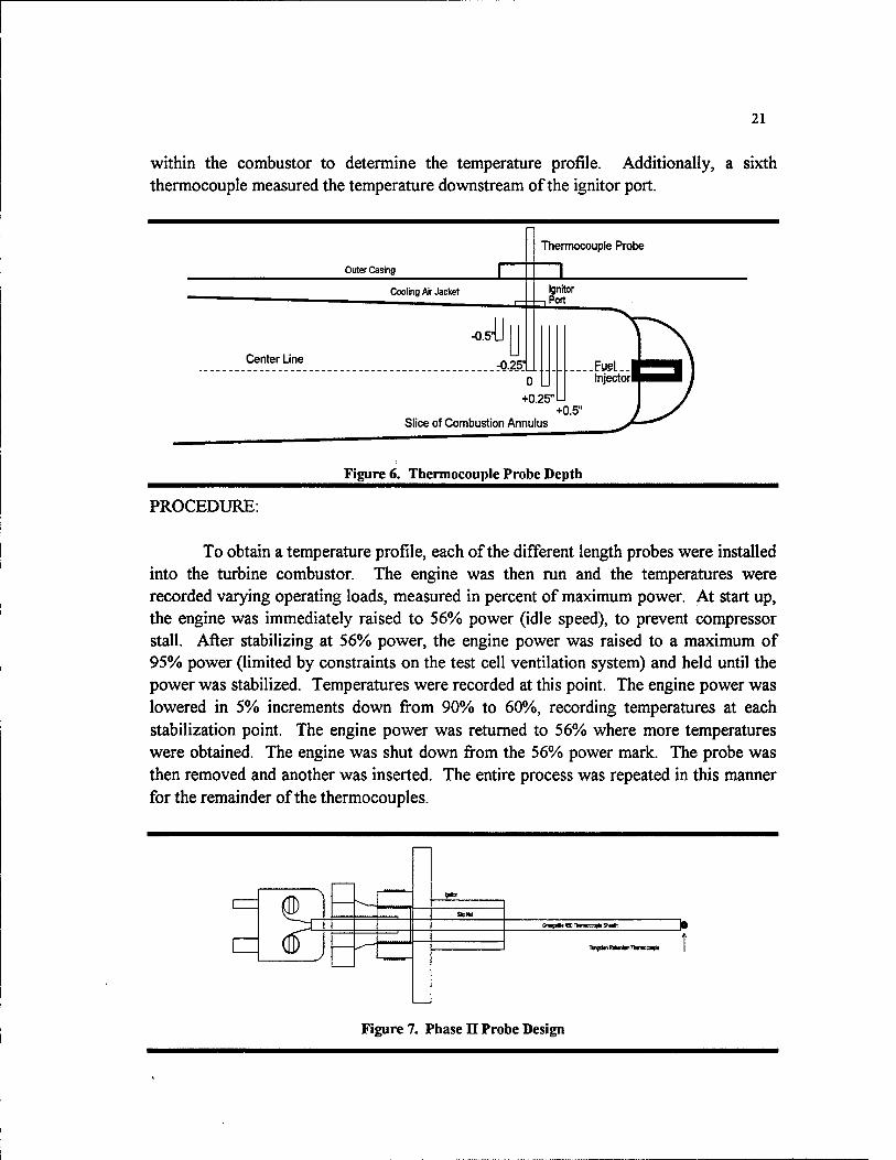
within the combustor to determine the temperature profile. Additionally, a sixth thermocouple measured the temperature dovsoistream of the ignitor port.
Thermocouple Probe
Figure 6. Thermocouple Probe Depth
PROCEDURE:
To obtain a temperature profile, each of the different length probes were installed into the turbine combustor. The engine was then run and the temperatures were recorded varying operating loads, measured in percent of maximum power. At start up, the engine was immediately raised to 56% power (idle speed), to prevent compressor stall. After stabilizing at 56% power, the engine power was raised to a maximum of 95% power (limited by constraints on the test cell ventilation system) and held until the power was stabilized. Temperatures were recorded at this point. The engine power was lowered in 5% increments down from 90% to 60%, recording temperatures at each stabilization point. The engine power was returned to 56% where more temperatures were obtained. The engine was shut down fi^om the 56% power mark. The probe was then removed and another was inserted. The entire process was repeated in this manner for the remainder of the thermocouples.
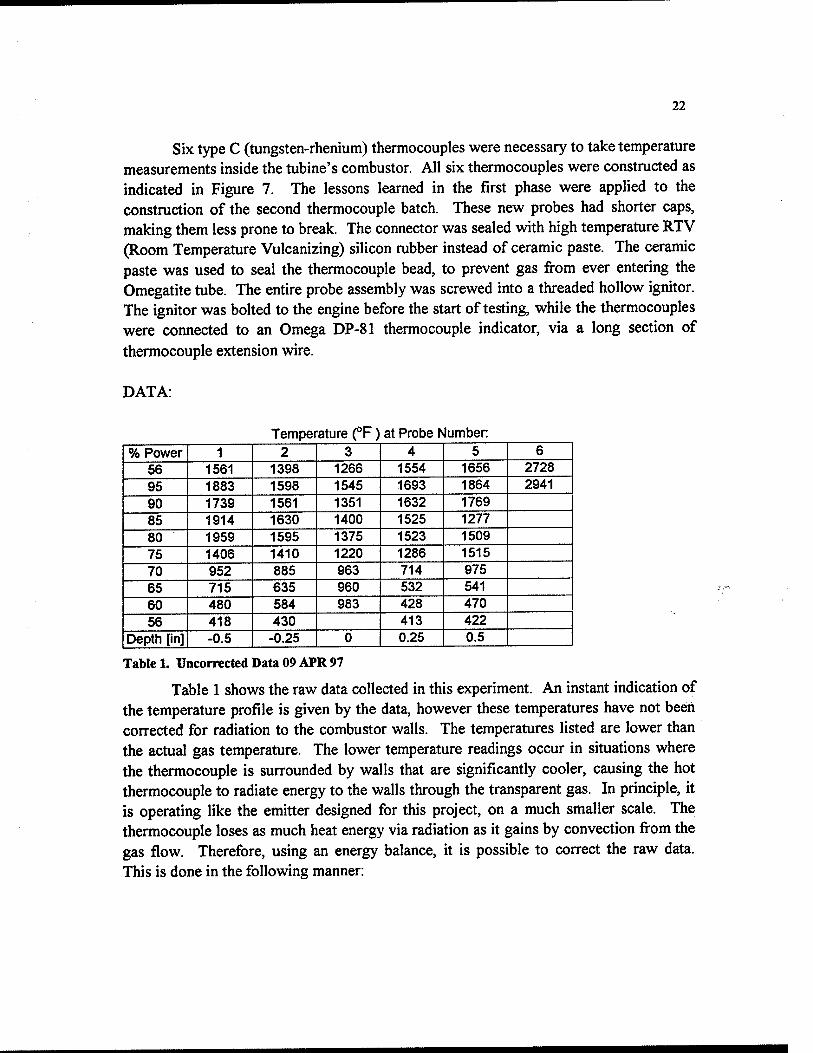
OnwgmN 45D TlwnneewpH Snwft
Ttfljnio Rlfllnim TrNfTDOCOUpIl
Figure 7. Phase n Probe Design
22
Six type C (tungsten-rhenium) thermocouples were necessary to take temperature measurements inside the tubine's combustor. All six thermocouples were constructed as indicated in Figure 7. The lessons learned in the first phase were applied to the construction of the second thermocouple batch. These new probes had shorter caps, making them less prone to break. The connector was sealed with high temperature RTV (Room Temperature Vulcanizing) silicon rubber instead of ceramic paste. The ceramic paste was used to seal the thermocouple bead, to prevent gas from ever entering the Omegatite tube. The entire probe assembly was screwed into a threaded hollow ignitor. The ignitor was bolted to the engine before the start of testing, while the thermocouples were connected to an Omega DP-81 thermocouple indicator, via a long section of thermocouple extension wire.
DATA:
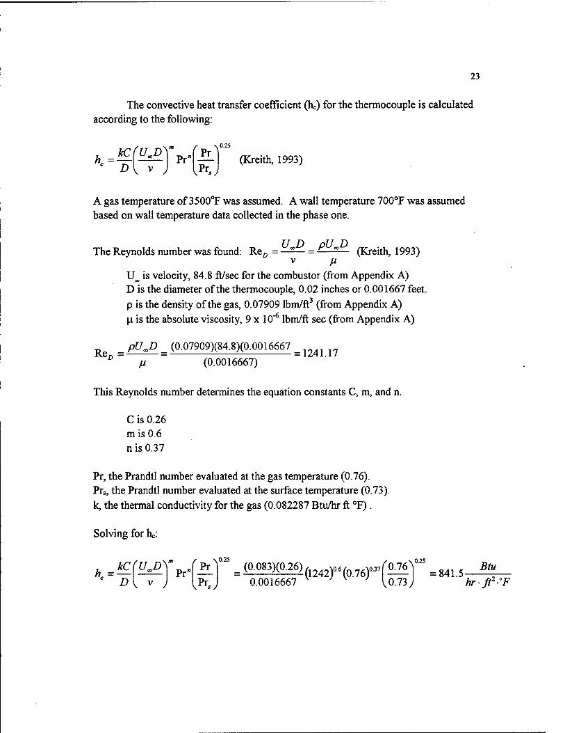
Temperature (°F) at Probe Number % Power 1 2 3 4 5 6
56 1561 1398 1266 1554 1656 2728
95 1883 1598 1545 1693 1864 2941
90 1739 1561 1351 1632 1769
85 1914 1630 1400 1525 1277
80 1959 1595 1375 1523 1509
75 1406 1410 1220 1286 1515
70 952 885 963 714 975 65 715 635 960 532 541 60 480 584 983 428 470 56 418 430 413 422
Depth [in] -0.5 -0.25 0 0.25 0.5
Table 1. Uncorrected Data 09 APR 97
Table 1 shows the raw data collected in this experiment. An instant indication of the temperature profile is given by the data, however these temperatures have not been corrected for radiation to the combustor walls. The temperatures listed are lower than the actual gas temperature. The lower temperature readings occur in situations where the thermocouple is surrounded by walls that are significantly cooler, causing the hot thermocouple to radiate energy to the walls through the transparent gas. In principle, it is operating like the emitter designed for this project, on a much smaller scale. The thermocouple loses as much heat energy via radiation as it gains by convection from the gas flow. Therefore, using an energy balance, it is possible to correct the raw data. This is done in the following manner:
23
The convective heat transfer coefficient (he) for the thermocouple is calculated according to the following:
'^-^
kC(UD\ Pr"
' Pr^
vP^.y (Kreith, 1993)
A gas temperature of 3500°F was assumed. A wall temperature 700°F was assumed based on wall temperature data collected in the phase one.
The Reynolds number was found: Re^ = —^— = ^ " (Kreith, 1993) V //
U^ is velocity, 84.8 ft/sec for the combustor (from Appendix A) D is the diameter of the thermocouple, 0.02 inches or 0.001667 feet. p is the density of the gas, 0.07909 Ibm/ft^ (from Appendix A) \i is the absolute viscosity, 9x10"^ Ibm/ft sec (from Appendix A)
Re ^ PU^D ^ (0.07909)(84.8)(0.0016667 ^^,^^ ^^ ^ fi (0.0016667)
This Reynolds number determines the equation constants C, m, and n.
C is 0.26 m is 0.6 n is 0.37
Pr, the Prandtl number evaluated at the gas temperature (0.76). Prs, the Prandtl number evaluated at the surface temperature (0.73). k, the thermal conductivity for the gas (0.082287 Btu/hr ft °F).
Solving for he:
// = D
fuM Pr"
^Pr^
vPr.y = (Q-^^^>(Q-^^>(l242)-(0.76)'
0.0016667 ^ ^ ^ ^ 0.76
0.73
.0.25
= 841.5- Btu
hrft'F
24
To find the actual gas temperature, To, an energy balance must be preformed. The heat convected to the thermocouple is equal to the heat radiated from the thermocouple.
KA,(T^ -T,)=Area{T; -T^,^) (Kreith, 1993)
TT is the thermocouple temperature, in °R. TwALL is the wall temperature, 1160°R (700°F). e, emissivity, is 0.53 for pure carbon, which coated the thermocouple during
testing. a, the Stephan Boltzman constant, 0.1714 x 10"* Btu/hr ft^ "R".
This yields the following equation, which was entered into the spreadsheet for correction.
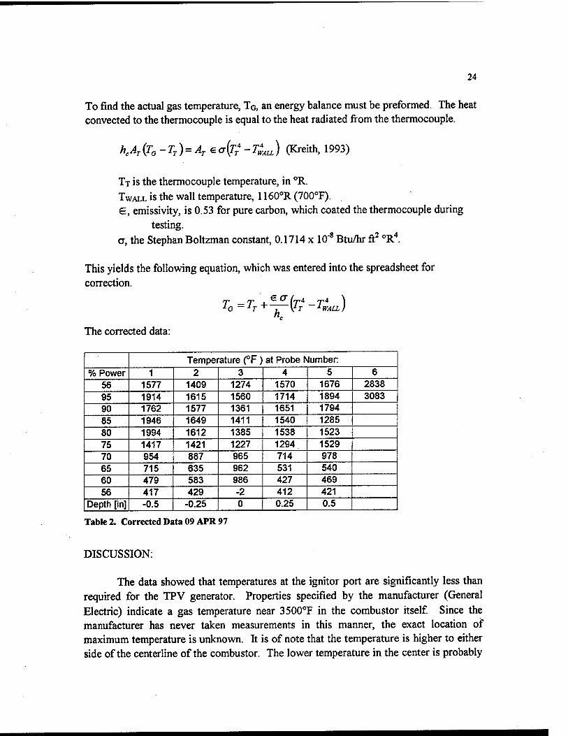
7Q — Tj + \^j I WALL)
The corrected data:
Temperature (°F) at Probe Number
% Power 1 2 3 4 5 6 56 J 1577 1409 1274 1570 1676 2838
95 1914 1615 1560 1714 1894 3083
90 1762 1577 1361 1651 1794
85 1946 1649 1411 1540 1285
80 1994 1612 1385 1538 1523
75 1417 1421 J 1227 1294 1529
70 954 887 965 714 978 65 715 635 962 531 540 60 479 583 986 427 469 56 417 429 -2 412 421
Depth [in] -0.5 -0.25 0 0.25 0.5
Table!. Corrected Data 09 APR 97
DISCUSSION:
The data showed that temperatures at the ignitor port are significantly less than required for the TPV generator. Properties specified by the manufacturer (General Electric) indicate a gas temperature near 3500°F in the combustor itself Since the manufacturer has never taken measurements in this manner, the exact location of maximum temperature is unknown. It is of note that the temperature is higher to either side of the centerline of the combustor. The lower temperature in the center is probably
25
due to the incomplete combustion of the fiiel. The centeriine is directly downstream of the fiiel injectors (Mellor, 1990). The fuel would burn outward from its fuel source, meaning that more complete combustion would have taken place by the time the gas reached the outer walls of the combustor. It may also be hotter toward the wall because of the influx of oxygen, since some cooling air enters the combustor along its walls.
Thermocouple six read a temperature of 3083°F before it meUed. Thermocouple six was installed 0.7 inches downstream of the ignitor port, at a depth of +0.5 inches from centeriine. The measured temperature is much closer to the predicted value. It is quite possible that the higher temperature was due to more complete combustion farther down stream from the ignition point. During turbine startup, the ignitor discharges a spark that ignites the atomized fuel, which starts burning at this point. Traveling downstream would allow more fuel to undergo oxidation, thus producing a higher gas temperature. Because the thermocouple melted so quickly, it is impossible to know if a stable temperature had been reached. As the temperature was steadily increasing at the point of failure, it can be assumed that the steady state temperature was greater than 3083°F. The tungsten rhenium thermocouples are intended for use in temperatures as high as 4200°F. It is possible that the temperature somewhere between the ignitor opening and the thermocouple exceeded 4200°F causing the thermocouple to melt away.
The temperatures varied greatly with power settings. The temperature profile roughly supports the notion that temperature increases with power output. This happens because the amount of fiiel being utilized would increase under loading. The additional fuel per unit time would cause more heat to be produced and then absorbed by both the thermocouple and by the combustor casing. The temperature varied particularly in the 80% power range, depending on the depth. The reason for such a variation could only be a change in the flow pattern within the combustor at this power level. The reduced airflow may be directed differently by the fuel injectors, moving the burning gases closer to the outside wall.

26
T-58 Temperature Profile
Depth [in]
-0.5
95 90
-0.25
85 80 75 70 65 Percent Power [%]
0 — +0.25 +0.5 +1"DS
Figures. T-58 Temperature Profile
CONCLUSIONS:
1. The temperature of the gas at the ignitor port is too low to power the thermophotovoltaic generator.
2. Much higher temperatures can be found downstream of the ignitor. It may be necessary to tap into the side of the combustor if continued combustion in the gas extraction tube is not sufficient to obtain the high temperatures needed for TPV power generation.
3. At a depth of-0.5 inches from the centerline, a maximum temperature occurred at 80% power.
27
4.0 PHASE II - SYSTEM DESIGN
4.1 INITIAL PARAMETERS
The initial design (Figure 9) of the thermophotovoltaic generator started as a device that would hold a 1-inch outer diameter tube and a smaller inner tube. Based on maximum flow calculations (Lindler, 1995) for the gas exiting the combustor, a Vi-inch inner diameter tube was deemed necessary to allow for the appropriate mass flow rate. A maximum mass flow rate of 305 Ib/hr could theoretically pass through the '/4-inch inner diameter tube. However, pressure drops and frictional losses cause the actual flow rate to be less. The actual mass flow rate was estimated to be about 200 Ib/hr (Lindler, 1995), yielding an estimated 18,000 Btu (British Thermal Units) of energy per hour (5276 Watts). The central core of the generator, the emitter, radiates this 18,000 Btu of energy each hour. With an assumed emissivity of 0.9 and an emitter temperature of 2400°F (to match the needs of the TPV cells), the emitter surface area was calculated to be 0.1744 fl^ (162 cm^). Based on a cylindrical geometry, and a height of 8 inches (20.32 cm), the corresponding diameter of the emitter was found to be about 1 inch (2.54 cm) (Lindler, 1995).

Zirconia
pm rm,.,.
-wmm.
QZSZSSZ
^AjihAA
steel Mounting Plate
^
Silico 1- Carbide
H Y/W/M?/>/A Boron Nitride
ru
^^ steel (other materials as marked)
rfTi rm.,
1
28
Figure 9. Preliminary Generator Design

29
4.2 MOUNTING SYSTEM
The initial generator design was large enough to accommodate up to a 10-inch emitter of 1-inch diameter. Because the steel plates are of considerable weight, a substantial mount for the generator was designed. The mount offers a flat surface to which the generator can be bolted. A system of brackets was designed, shown in Figure 10, that could be bolted to the existing flanges that separate the combustor section from the compressor and turbine sections of the gas turbine. The flanges are of different diameters and have different boh patterns, as shown in Figure 11, requiring individual design for each of four brackets. The brackets were then cut from 3/16-inch low carbon steel. Low carbon steel was chosen over stainless steel because it is easier to drill and fold, and is readily available. To form a flat surface to attach the mounting plate, each bracket was bent so that the folded pieces would all form a parallel surface.
Figure 10. Front Mounting Brackets
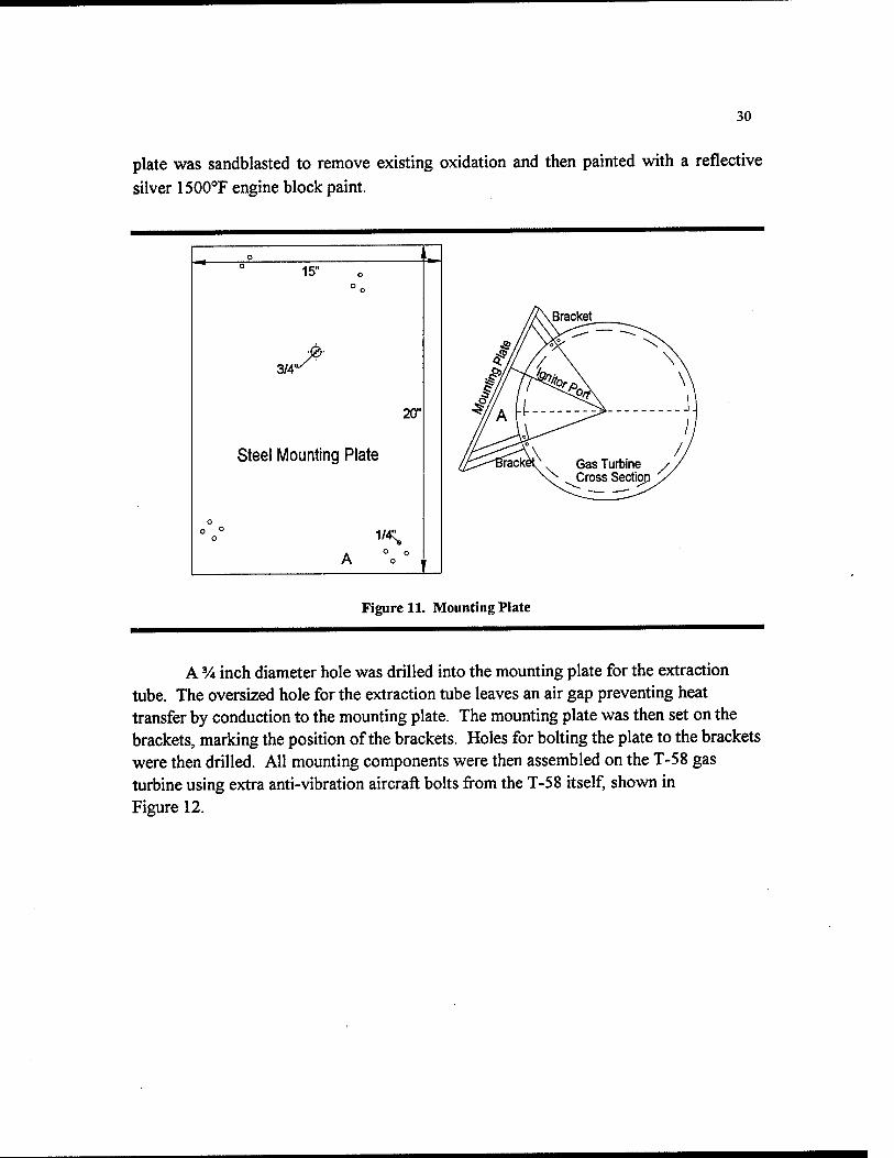
The mounting plate was cut from the same type of low carbon steel. The mounting plate was Vi inch thick, 15 inches wide and 20 inches long, as shown in Figure 11. The extents of the plate are larger than the dimensions of the TPV generator in order to accommodate the edges of the four brackets. The oversize provides a workstation area that could be used for future emitter/TPV experiments. The large size also dissipates any heat conducted to the mounting plate. To prevent oxidation, the mounting
30
plate was sandblasted to remove existing oxidation and then painted with a reflective silver 1500°F engine block paint.
3/4'
15"
^
20'
Steel Mounting Plate
1/4^
Figure 11. Mounting Plate
A % inch diameter hole was drilled into the mounting plate for the extraction tube. The oversized hole for the extraction tube leaves an air gap preventing heat transfer by conduction to the mounting plate. The mounting plate was then set on the brackets, marking the position of the brackets. Holes for bolting the plate to the brackets were then drilled. All mounting components were then assembled on the T-58 gas turbine using extra anti-vibration aircraft bolts jfrom the T-58 itself, shown in Figure 12.
31
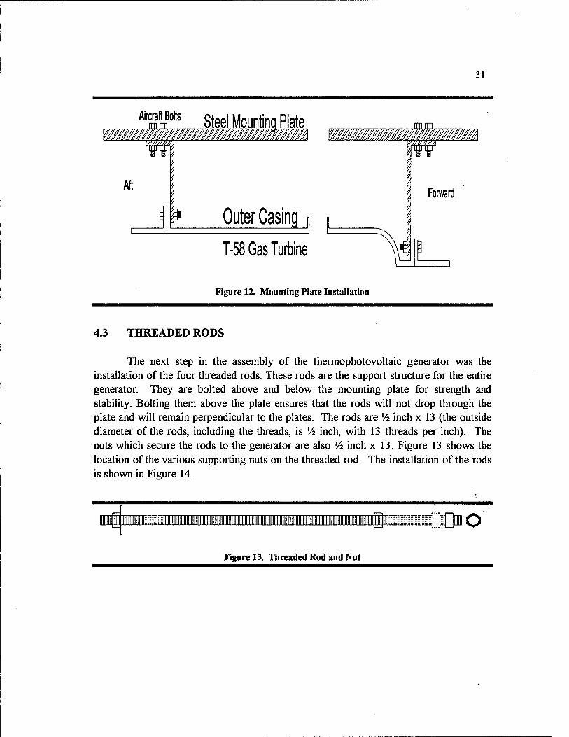
Steel Mounting Plate DSL m
Outer Casing
T-58 Gas Turbine
Figure 12. Mounting Plate Installation
4.3 THREADED RODS
The next step in the assembly of the thermophotovoltaic generator was the installation of the four threaded rods. These rods are the support structure for the entire generator. They are bolted above and below the mounting plate for strength and stability. Bolting them above the plate ensures that the rods will not drop through the plate and will remain perpendicular to the plates. The rods are V2 inch x 13 (the outside diameter of the rods, including the threads, is V2 inch, with 13 threads per inch). The nuts which secure the rods to the generator are also V2 inch x 13. Figure 13 shows the location of the various supporting nuts on the threaded rod. The installation of the rods is shown in Figure 14.
Figure 13. Threaded Rod and Nut
32
'''''" w-
'^- «
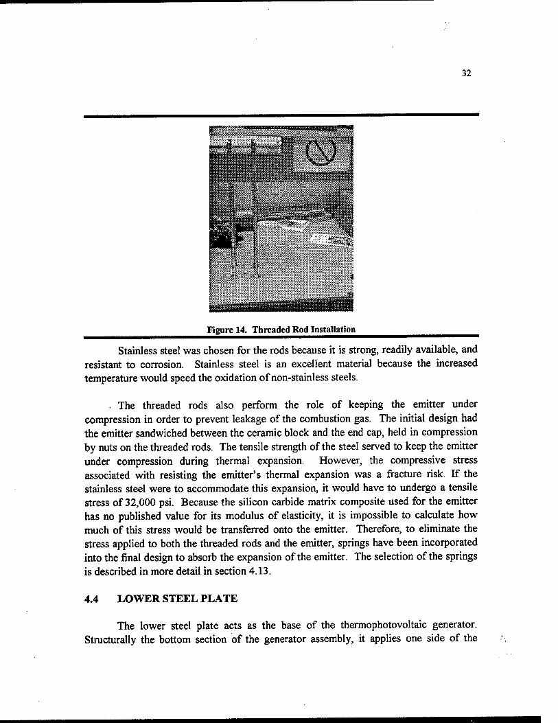
Figure 14. Threaded Rod Installation
Stainless steel was chosen for the rods because it is strong, readily available, and resistant to corrosion. Stainless steel is an excellent material because the increased temperature would speed the oxidation of non-stainless steels.
. The threaded rods also perform the role of keeping the emitter under compression in order to prevent leakage of the combustion gas. The initial design had the emitter sandwiched between the ceramic block and the end cap, held in compression by nuts on the threaded rods. The tensile strength of the steel served to keep the emitter under compression during thermal expansion. However, the compressive stress associated with resisting the emitter's thermal expansion was a fracture risk. If the stainless steel were to accommodate this expansion, it would have to undergo a tensile stress of 32,000 psi. Because the silicon carbide matrix composite used for the emitter has no published value for its modulus of elasticity, it is impossible to calculate how much of this stress would be transferred onto the emitter. Therefore, to eliminate the stress applied to both the threaded rods and the emitter, springs have been incorporated into the final design to absorb the expansion of the emitter. The selection of the springs is described in more detail in section 4.13.
4.4 LOWER STEEL PLATE
The lower steel plate acts as the base of the thermophotovoltaic generator. Structurally the bottom section of the generator assembly, it applies one side of the
33
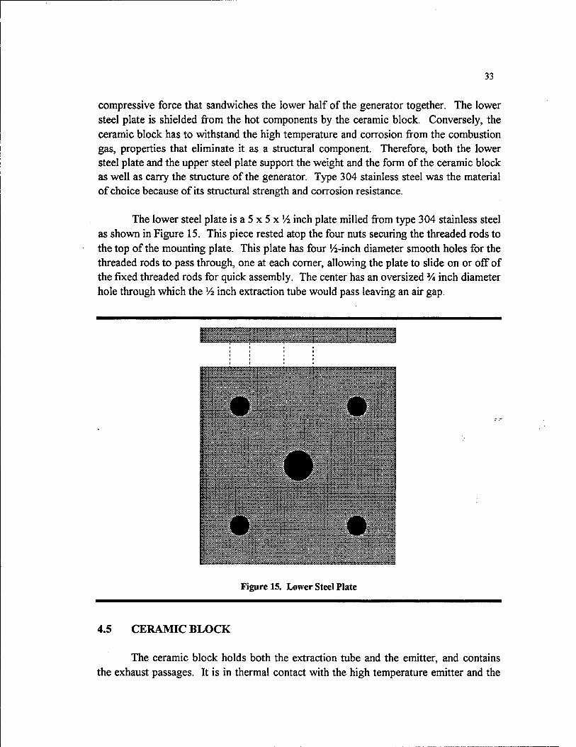
compressive force that sandwiches the lower half of the generator together. The lower steel plate is shielded from the hot components by the ceramic block. Conversely, the ceramic block has to withstand the high temperature and corrosion from the combustion gas, properties that eliminate it as a structural component. Therefore, both the lower steel plate and the upper steel plate support the weight and the form of the ceramic block as well as carry the structure of the generator. Type 304 stainless steel was the material of choice because of its structural strength and corrosion resistance.
The lower steel plate is a 5 x 5 x V2 inch plate milled from type 304 stainless steel as shown in Figure 15. This piece rested atop the four nuts securing the threaded rods to the top of the mounting plate. This plate has four '/4-inch diameter smooth holes for the threaded rods to pass through, one at each comer, allowing the plate to slide on or off of the fixed threaded rods for quick assembly. The center has an oversized % inch diameter hole through which the V2 inch extraction tube would pass leaving an air gap.
Figure 15. Lower Steel Plate
4.5 CERAMIC BLOCK
The ceramic block holds both the extraction tube and the emitter, and contains the exhaust passages. It is in thermal contact with the high temperature emitter and the

34
extraction tube. Its purpose is to hold the emitter and extraction/gas tubes and redirect gas flow from the base of the emitter into the exhaust channel. The ceramic block also protects the structural upper and lower steel plates from high temperatures.
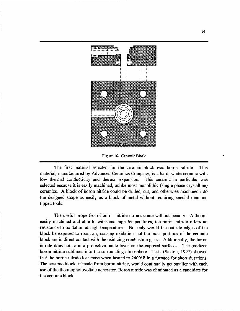
A 5 X 5 X lV2-inch block was machined to hold the extraction tube and the emitter by drilling concentric holes of varying diameters at different depths as shown in Figure 16. The central hole was '/a inch in diameter to hold the extraction tube. This hole went completely through the block. Next, a ^-inch hole was drilled into the block to a depth of 5/8 inch. This hole collects and redirects the exhaust gases out of the block through a '/2-inch hole drilled from the side of the block. Lastly, 1-inch and 1'/2-inch holes were drilled in the center of the block, extending down '/4 inch and 1/8 inch respectively. These cuts allowed for the installation of a 1-inch or l'/2-inch diameter emitter.
Because of the complex design of the ceramic block, material selection became extremely important. The material would have to withstand high temperatures without being adversely affected, yet retain some ability to be machined. When working with ceramics, this seems an impossible combination. The material would also have a small thermal conductivity to limit the heat conducted to the stainless steel components. It must also have a low thermal expansion rate. This block undergoes some thermal expansion. However, it cannot be allowed to expand more than the steel plates without damaging them. As the block prevents the steel plates from heating up, it was impossible to design both components with equal expansion rates.
35
Figure 16. Ceramic Block
The first material selected for the ceramic block was boron nitride. This material, manufactured by Advanced Ceramics Company, is a hard, white ceramic with low thermal conductivity and thermal expansion. This ceramic in particular was selected because it is easily machined, unlike most monolithic (single phase crystalline) ceramics. A block of boron nitride could be drilled, cut, and otherwise machined into the designed shape as easily as a block of metal without requiring special diamond tipped tools.
The useful properties of boron nitride do not come without penalty. Although easily machined and able to withstand high temperatures, the boron nitride offers no resistance to oxidation at high temperatures. Not only would the outside edges of the block be exposed to room air, causing oxidation, but the inner portions of the ceramic block are in direct contact with the oxidizing combustion gases. Additionally, the boron nitride does not form a protective oxide layer on the exposed surfaces. The oxidized boron nitride sublimes into the surrounding atmosphere. Tests (Saxton, 1997) showed that the boron nitride lost mass when heated to 2400°F in a furnace for short durations. The ceramic block, if made fi-om boron nitride, would continually get smaller with each use of the thermophotovoltaic generator. Boron nitride was eliminated as a candidate for the ceramic block.

36
The next idea proposed (Patterson, 1997) for the ceramic block was to use bronze with water cooling channels. Bronze would be easy to machine, readily available, and inexpensive. Soldering copper tubing to the outside block could provide cooling water. This idea, although an excellent solution for the block itself, is not practical for the thermophotovoltaic generator. Heat removed from the block by cooling water lowers the amount of heat energy available to the emitter. Heating the emitter to 2400°F is paramount to the success of the design, rendering the bronze block idea unusable.
A third material was suggested for the ceramic block (Patterson, 1997). The material was another machinable ceramic, aluminum silicate. The aluminum silicate is temperature tolerant and will not sublime in an oxidizing environment. It has almost no thermal expansion—after firing. The aluminum silicate is easily machined before firing, able to be scratched with a fingernail.
The firing process involves slowly heating the components up to 2000°F in a fiimace. Testing of the aluminum silicate on 01 April 1997, showed that the firing process hardens the ceramic and causes a 2% expansion in size. This meant that all dimensions of the final product had to be decreased by 2% before machining to account for this expansion. The ceramic block was machined to from the aluminum silicate and then fired in a furnace for 16 hours at temperatures as high as 2000°F.
The aluminum silicate material also simplifies the attachment of the extraction tube and the gas tube. Because the aluminum silicate is easily machined, it was possible to cut a collar from the block and then thread both pieces. This collar compresses an alumina fiber seal when tightened. As the seal compresses, its inside diameter decreases, forming a tight seal around the extraction/gas tube. The new seal design required the center hole to be increased in diameter, allowing clearance for the extraction/gas tube.
37
4.6 EXTRACTION TUBE
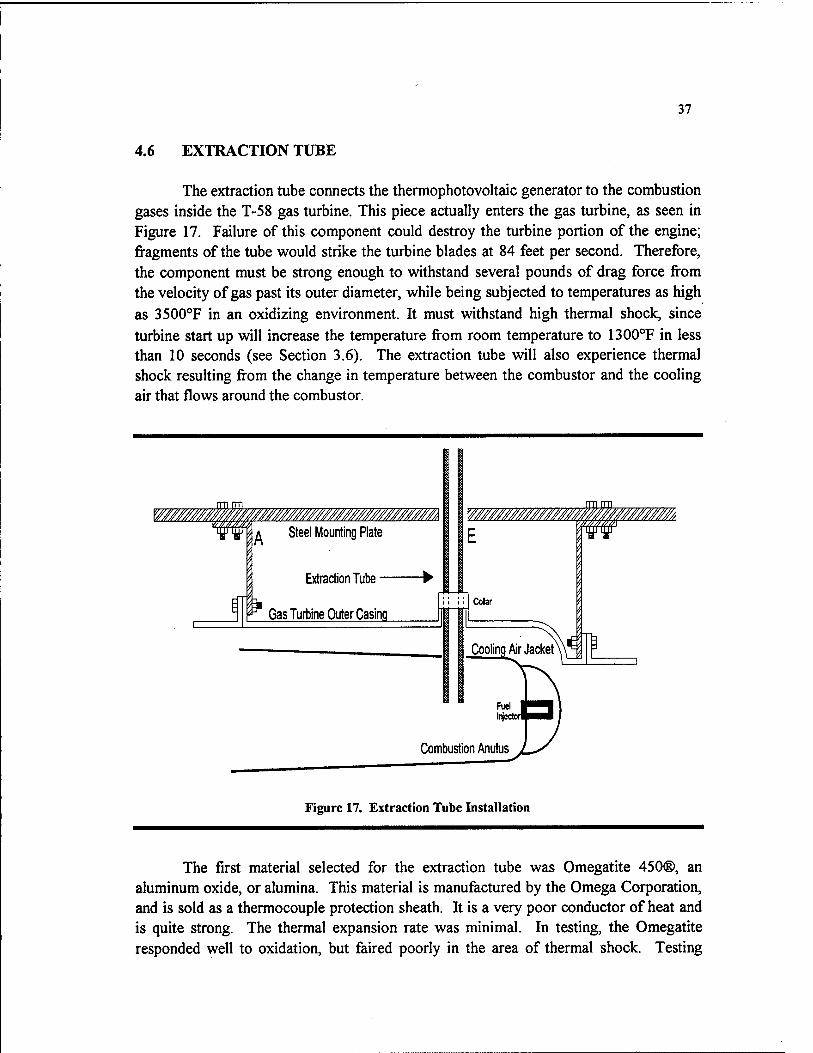
The extraction tube connects the thermophotovoltaic generator to the combustion gases inside the T-58 gas turbine. This piece actually enters the gas turbine, as seen in Figure 17. Failure of this component could destroy the turbine portion of the engine; fragments of the tube would strike the turbine blades at 84 feet per second. Therefore, the component must be strong enough to withstand several pounds of drag force from the velocity of gas past its outer diameter, while being subjected to temperatures as high as 3500°F in an oxidizing environment. It must withstand high thermal shock, since turbine start up will increase the temperature from room temperature to 1300°F in less than 10 seconds (see Section 3.6). The extraction tube will also experience thermal shock resulting from the change in temperature between the combustor and the cooling air that flows around the combustor.
Figure 17. Extraction Tube Installation
The first material selected for the extraction tube was Omegatite 450®, an aluminum oxide, or alumina. This material is manufactured by the Omega Corporation, and is sold as a thermocouple protection sheath. It is a very poor conductor of heat and is quite strong. The thermal expansion rate was minimal. In testing, the Omegatite responded well to oxidation, but faired poorly in the area of thermal shock. Testing
38
conducted with an oxy-acetylene torch (see Appendix B) resuhed in the destmction of the material under slight vibration and even under no load. This material would be unsuitable for this application.
The next material choice for the extraction tube was zirconia (zirconium oxide). Zirconia is monolithic ceramic touted as having the very best thermal shock characteristics. Testing proved this reputation to be false (Saxton, 1997). The zirconia sample detonated when touched by the flame of the oxy-acetylene torch making it unsuitable for use inside the gas turbine.
Because of the physical and thermal stresses that the component would undergo inside the turbine, it was suggested that a monolithic composite would not be appropriate for this application (Patterson, 1997). A ceramic composite would exhibit better qualities for such an application. It was also recommended that a singular tube be used for both the extraction tube and the gas tube, because it would be easier to construct and easier to seal inside the ceramic block (Patterson, 1997). Pure silicon carbide would be able to vdthstand the high temperatures and the stresses, but would suffer oxidation. A silicon carbide fiber composite could be densified with an inert ceramic to protect it jfrom oxidation. Two designs were proposed: a short lead-time, single-weave silicon carbide-fiber tube, densified with silicon carbide and halfnium carbide, and a longer lead-time, triple-weave version. The first design would successfiiUy extract the necessary gases fi-om the turbine combustor, while the second would specifically improve the emissivity of the gas tube.
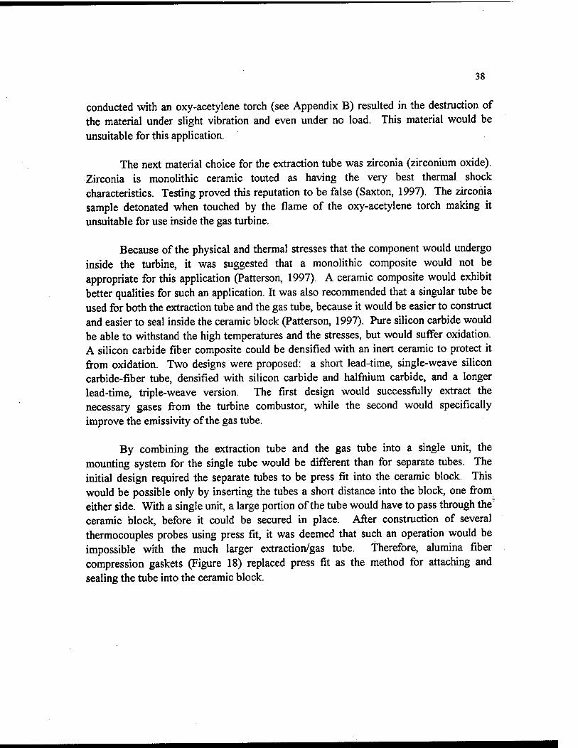
By combining the extraction tube and the gas tube into a single unit, the mounting system for the single tube would be different than for separate tubes. The initial design required the separate tubes to be press fit into the ceramic block. This would be possible only by inserting the tubes a short distance into the block, one from either side. With a single unit, a large portion of the tube would have to pass through the' ceramic block, before it could be secured in place. After construction of several thermocouples probes using press fit, it was deemed that such an operation would be impossible with the much larger extraction/gas tube. Therefore, alumina fiber compression gaskets (Figure 18) replaced press fit as the method for attaching and sealing the tube into the ceramic block.
39
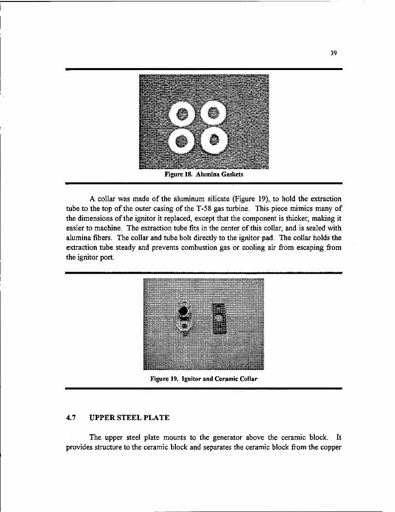
A collar was made of the aluminum silicate (Figure 19), to hold the extraction tube to the top of the outer casing of the T-58 gas turbine. This piece mimics many of the dimensions of the ignitor it replaced, except that the component is thicker, making it easier to machine. The extraction tube fits in the center of this collar, and is sealed with alumina fibers. The collar and tube bolt directly to the ignitor pad. The collar holds the extraction tube steady and prevents combustion gas or cooling air from escaping from the ignitor port.
Figure 19. Ignitor and Ceramic Collar
4.7 UPPER STEEL PLATE
The upper steel plate mounts to the generator above the ceramic block. It provides structure to the ceramic block and separates the ceramic block from the copper

40
cooling module. Type 304 stainless steel was used for this component because of its resistance to oxidation, especially when heated. The plate design is shown in Figure 20.
^^^^^^^^^^^ ̂ ^^^^^^1 ^^^^^^^^^^^^^^^s^ ̂ ^^^^:^«S«W * ^^ ^^ ^^^^ ̂ ^^^^
11 h^i IB H ̂ ^^^Hl Hi 1 ̂ ^^B ̂ ^^B ^^^& ̂ ^^^^ ^^»« fflSSS^Sg ^^^^^^ ^^^^^
^^H H ̂ Bi H^^B ^^^p ̂ ^^^^ ̂ ^^^ ^^^^^^ ■ 1 1 1 1 ■
Figure 20. Upper Steel Plate
The upper steel plate slides over the threaded rods, resting atop the ceramic block. Depending on whether or not the cooling module is installed, the nuts, which secure the lower assembly in compression, bolt directly on the upper steel plate or just above the lower foot of the cooling module. The upper steel plate distributes the pressure of these nuts over the 25 square inches of the ceramic block's top.
4.8 GAS TUBE
The gas tube (which has been combined with the extraction tube) takes the combustion gas to the top of the generator where it is turned 180 degrees. The gas then travels in the space between the gas tube and the inside surface of the emitter itself It is necessary to direct the gas to the top of the generator and then double back down the length of the emitter in order to achieve a uniform emitter temperature. The uniform temperature distribution is critical to the efficient operation of the thermophotovoltaic cells. The gas tube is shown with the extraction tube in Figure 21.
Extraction Tube Gas Tube t^vM/uvyy mMMjvMju
O D C3
Figure 21. Extraction/Gas Tube

41
The initial concept offered several ideas to uniformly distribute the temperature across the emitter's length. Assuming no inside tube, the hot combustion gas would start at the base of the emitter and rise to the top and be exhausted. This causes the highest emitter temperature to be at the very bottom, where the gas temperature is greatest. The temperatures would decrease up the length of the emitter, as the combustion gas cooled. The coldest point would be at the very top of the emitter. This linearly decreasing temperature profile would not be optimal for thermophotovoltaic energy conversion, as the wavelengths of emitted light change with temperature.
An inner gas tube could be installed inside the emitter to direct the gas flow for a more uniform temperature distribution. One method would have holes in the gas tube, which would port hot gas into the emitter tube at several points down its length, varying the mass flow of gas along the length of the emitter. The design, size, shape, placement, and number of holes are all variable. The first method was dismissed because a simpler method was found.
The second method uses a solid gas tube and a turning vane at the end to redirect the gas in the opposite direction, sending the hottest gases to the top of the generator. At the bottom of the generator, the temperature of the gas is greatest. The gas loses heat to its surroundings as it travels upwards in the gas tube, heating the walls of the gas tube. The hot gas tube radiates heat to the emitter. The gas at the top of the generator is cooler because some heat has transferred to the gas tube. The gas is redirected toward the bottom of the generator, and passes through the space between the gas tube and emitter. The gas heats the emitter by convection. However, because the gas temperature is decreasing as it travels toward the bottom of the generator, the emitter surface temperature also decreases. The additional radiant energy fi-om the gas tube makes up for the reduced convective heat transfer at the bottom of the generator (see Figure 22). This design was intensively modeled by Dr. Keith Lindler with a Quattro Pro spreadsheet, and subsequently selected for the actual generator design (Lindler, 1995).
The gas tube must withstand high temperature and oxidation. These parameters quickly eliminated the possibility of using refi^actory metals for this component. Initially, the gas tube was to be made of the Omegatite 450, which, after testing, was eliminated because of its inability to withstand thermal shock. Also eliminated after testing was zirconia, which detonated when rapidly heated. Silicon carbide seemed to be the best monolithic ceramic for this component, but a V4 inch diameter tube of this material was not available. Therefore, a silicon carbide ceramic matrix composite was selected for this component. For simplicity of construction, the gas tube was combined with the extraction tube, to be woven as a single piece from silicon carbide fiber. The weave is densified with silicon carbide and halfnium carbide for forty hours (Patterson,

42
1997). The ceramic composite offers the advantage of having high strength and temperature tolerance, while capable of being rolled to any specified diameter. The densification process allov^s the composite to be impregnated with materials that will be less affected by the oxidizing environment.
W////M W/Am'M'///i>i/M^
G« Turtint OuItT Ctsino
W!7?M
Figure 22. Emitter/Gas Tube Installation
The drawing shows both a 1-inch and 1.5 inch emitter tube positioned around the gas tube.
4.9 EMITTER
The emitter is the heart of the thermophotovoltaic generator. It is the emitter that converts the heat energy from the combustion process into thermal radiation, for conversion to electricity by the thermophotovoltaic cells. Because of the critical nature of this component, the optimization of the emitter material is an entire project in itself (Saxton, 1997).
43
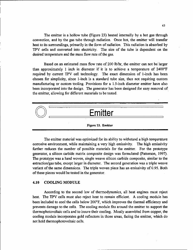
The emitter is a hollow tube (Figure 23) heated internally by a hot gas through convection, and by the gas tube through radiation. Once hot, the emitter will transfer heat to its surroundings, primarily in the form of radiation. This radiation is absorbed by TPV cells and converted into electricity. The size of the tube is dependent on the desired temperature and the mass flow rate of the gas.
Based on an estimated mass flow rate of 200 Ib/hr, the emitter can not be larger than approximately 1 inch in diameter if it is to achieve a temperature of 2400°F required by current TPV cell technology. The exact dimension of 1-inch has been chosen for simplicity, since 1-inch is a standard tube size, thus not requiring custom manufacturing or custom tooling. Provisions for a 1.5-inch diameter emitter have also been incorporated into the design. The generator has been designed for easy removal of the emitter, allowing for different materials to be tested.
Emitter Figure 23. Emitter
The emitter material was optimized for its ability to withstand a high temperature corrosive environment, while maintaining a very high emissivity. The high emissivity further reduces the number of possible materials for the emitter. For the prototype generator, a silicon carbide matrix composite design was formulated (Patterson, 1997). The prototype was a hand woven, single weave silicon carbide composite, similar to the extraction/gas tube, except larger in diameter. The second generation was a triple weave variant of the same dimensions. The triple woven piece has an emissivity of 0.95. Both of these pieces would be tested in the generator.
4.10 COOLING MODULE
According to the second law of thermodynamics, all heat engines must reject heat. The TPV cells must also reject heat to remain efficient. A cooling module has been included to cool the cells below 200°F, which improves the thermal efficiency and prevents damage to the cells. The cooling module fits around the emitter to support the thermophotovoltaic cells and to insure their cooling. Mostly assembled from copper, the cooling module incorporates gold reflectors in those areas, facing the emitter, which do not hold thermophotovoltaic cells.
44
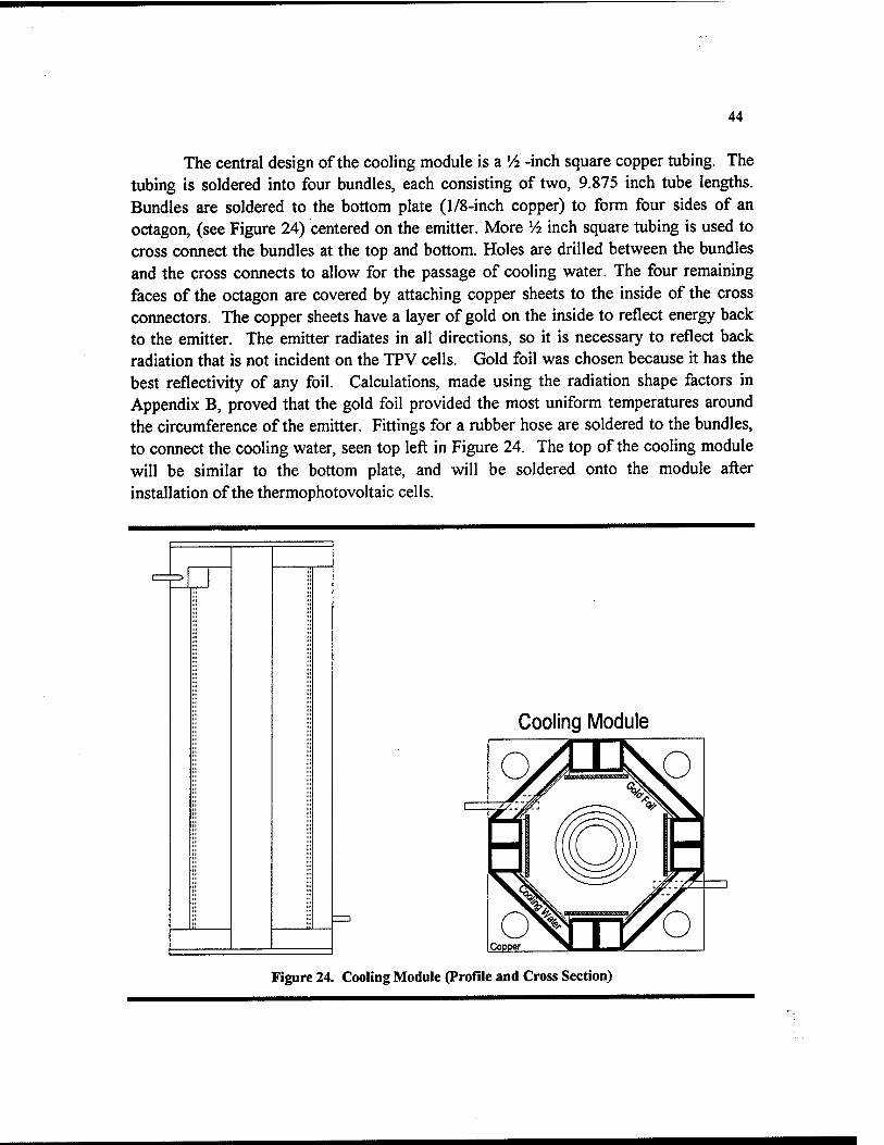
The central design of the cooling module is a V2 -inch square copper tubing. The tubing is soldered into four bundles, each consisting of two, 9.875 inch tube lengths. Bundles are soldered to the bottom plate (1/8-inch copper) to form four sides of an octagon, (see Figure 24) centered on the emitter. More 14 inch square tubing is used to cross connect the bundles at the top and bottom. Holes are drilled between the bundles and the cross connects to allow for the passage of cooling water. The four remaining faces of the octagon are covered by attaching copper sheets to the inside of the cross connectors. The copper sheets have a layer of gold on the inside to reflect energy back to the emitter. The emitter radiates in all directions, so it is necessary to reflect back radiation that is not incident on the TPV cells. Gold foil was chosen because it has the best reflectivity of any foil. Calculations, made using the radiation shape factors in Appendix B, proved that the gold foil provided the most uniform temperatures around the circumference of the emitter. Fittings for a rubber hose are soldered to the bundles, to connect the cooling water, seen top left in Figure 24. The top of the cooling module will be similar to the bottom plate, and will be soldered onto the module after installation of the thermophotovoltaic cells.
Cooling Module
Figure 24. Cooling Module (Profile and Cross Section)
45
Thermophotovoltaic cells, mounted to copper plates, will be fastened to the inside of the bundles with high temperature adhesive. The copper backing will conduct the heat from the cells to the bundles where the cooling water will absorb the heat energy. Copper has been selected for the cooling module because it is easy to work and has excellent thermal conductivity. Cooling water flow rate will be adjustable to maintain the thermophotovoltaic cells well below 200°F.
The cooling module was not designed as a structural member, but should be strong enough to protect the cells. The top and bottom of the module will have holes for the threaded rods. The bottom will be secured to the upper steel plate with four nuts. These nuts will firmly anchor the cooling module to the lower generator assembly.
4.11 STEEL END CAP
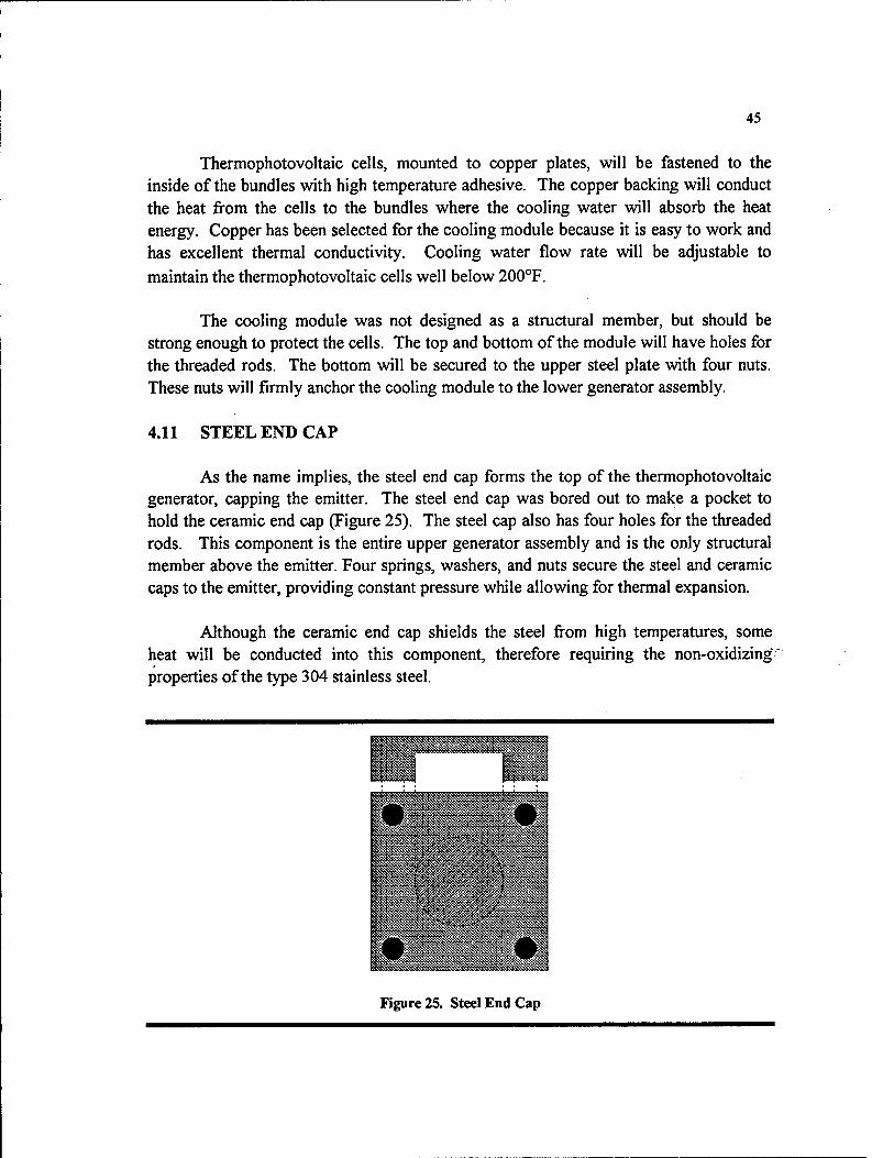
As the name implies, the steel end cap forms the top of the thermophotovoltaic generator, capping the emitter. The steel end cap was bored out to make a pocket to hold the ceramic end cap (Figure 25). The steel cap also has four holes for the threaded rods. This component is the entire upper generator assembly and is the only structural member above the emitter. Four springs, washers, and nuts secure the steel and ceramic caps to the emitter, providing constant pressure while allowing for thermal expansion.
Although the ceramic end cap shields the steel from high temperatures, some heat will be conducted into this component, therefore requiring the non-oxidizing properties of the type 304 stainless steel.
Figure 25. Steel End Cap
46
Initially bolted to the top of the generator using four nuts on the threaded rods, this design did not account for the thermal expansion of the emitter or the gas tube. Because of the high thermal loads and the brittleness of ceramic materials, the upper generator assembly was redesigned to accommodate thermal expansion, relieving stress placed on the emitter. Four large springs hold the steel end cap in place against the force of the combustion gas impinging on the ceramic end cap, providing up to 247 pounds of force and preventing gas from escaping from around the edges of the emitter.
4.12 CERAMIC END CAP
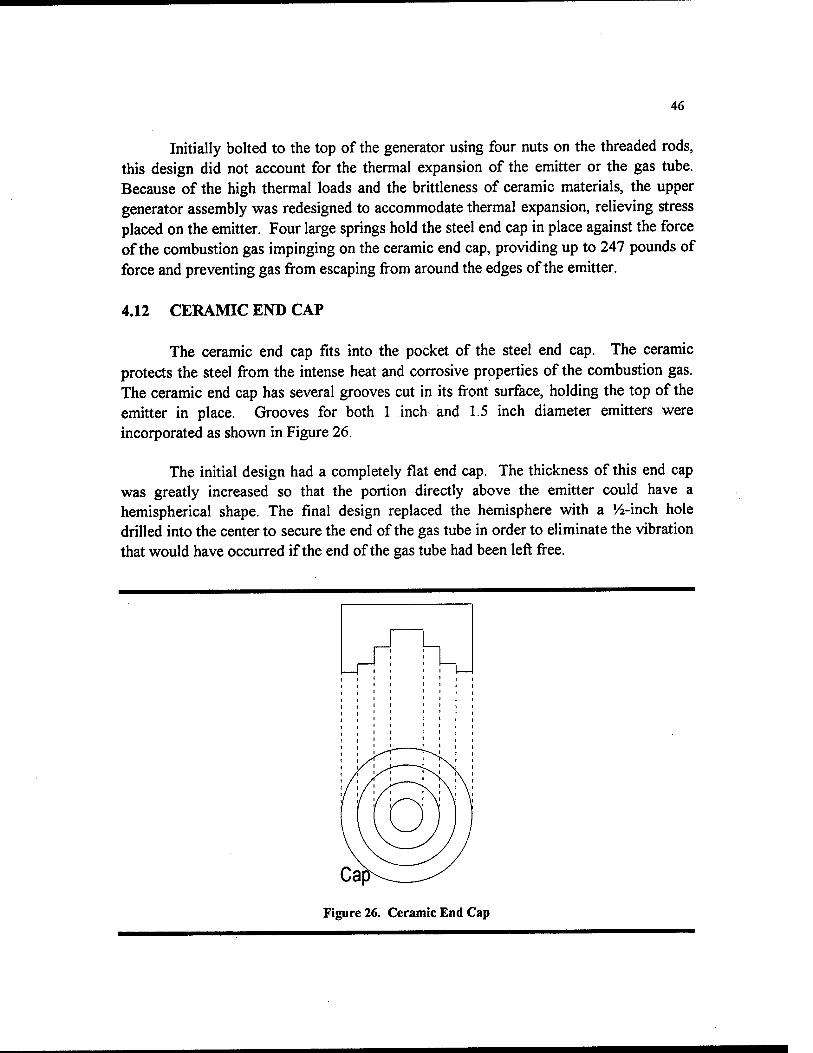
The ceramic end cap fits into the pocket of the steel end cap. The ceramic protects the steel from the intense heat and corrosive properties of the combustion gas. The ceramic end cap has several grooves cut in its front surface, holding the top of the emitter in place. Grooves for both 1 inch and 1.5 inch diameter emitters were incorporated as shown in Figure 26.
The initial design had a completely flat end cap. The thickness of this end cap was greatly increased so that the portion directly above the emitter could have a hemispherical shape. The final design replaced the hemisphere with a '/2-inch hole drilled into the center to secure the end of the gas tube in order to eliminate the vibration that would have occurred if the end of the gas tube had been left free.
Figure 26. Ceramic End Cap

47
The prototype ceramic end cap was machined from aluminum silicate, having the same material requirements as the ceramic block. Originally the component was to be made from boron nitride. This material, while machinable, would have sublimed in those areas in contact with the combustion gas. Zirconia was also considered, but its thermal shock characteristics were not nearly as promising. Because of the similar requirements for the material, the same aluminum silicate was chosen for the ceramic end cap as the ceramic block. The cap was machined and then fired. The dimensions were altered 2% to offset the firing expansion. The completed cap assembly is shown in Figure 27.
^^^ ^^^^^^^ '^%%%%^ ^s Ceramic End Cap ^S
-^^
Figure 27, Ceramic and Steel End Cap
4.13 SPRINGS
Springs were not originally part of the design. Concern for compressive stress on the emitter brought about the use of springs to hold the steel end cap in place above the emitter. The springs allow for the thermal expansion of the emitter without stretching the threaded rods. The modulus of elasticity for the emitter is not known, due to its custom made composite nature, preventing a calculation for the deformation of the emitter and threaded rods when the force of the expanding emitter is applied.
Normally, one component undergoes compression while the other is in tension, reaching an equilibrium point. The equilibrium point is derived from the modulus of elasticity for each material. Even without knowing the modulus for the emitter, experience suggests that the stainless steel threaded rods will not deform appreciably. The force of thermal expansion would then act on the emitter, compressing it to its unheated length. Compressive stress could lead to emitter failure. The springs allow the end cap to float upwards, providing sufficient force to prevent combustion gas leakage without excessive force on the emitter.
48
Because the springs compress due to the expansion of the emitter, some force will be applied in the opposite direction, trying to compress the emitter. Since force on the emitter is to be as low as possible, the springs must be as small as possible. A worst case expansion for the emitter was calculated using the expansion rate of silicon/silicon carbide, which has an order of magnitude greater expansion rate than other silicon carbide ceramics. The thermal expansion of a 10-inch emitter would be approximately 0.1 inches. The lightest springs that would fit on the threaded rods produced 6 pounds of force on the emitter when compressed 0.1 inches. The springs have the additional advantage of preloading to deliver a known force. It is possible to increase or decrease the force on the emitter by adjusting the top nuts, allowing experimental compensation.
A spreadsheet was developed to predict the velocity of the gas at the ceramic end cap. The velocity of the gas, changing directions 180° at the end cap, imparts a force calculated to be 247 pounds. Therefore, the small springs, providing only 6 pounds of force, would not maintain the seal with the ceramic end cap. The force of the gas would lift the steel end cap off the emitter and gas would escape through the gap. Springs that could provide 247 pounds were necessary to counteract the force imparted by the moving gas. To deliver this force, M&R Springs MC125Q01-N were selected. The springs were compressed 0.35 inches during assembly to provide the 247 pounds of force needed to seal the combustion gas. All 247 pounds of precompressive force act directly on the emitter when no gas is flowing. To prevent cold compression of the emitter caused by the downward travel of the steel end cap, the cooling module has been designed to limit the motion of the cap.

49
5.0 PHASE III - FINAL DESIGN
5.1 ASSEMBLY OF THERMOPHOTOVOLTAIC GENERATOR
5.1.2 LIST OF COMPONENTS
KEY COMPONENT NAME MATERIAL SOURCING A Mounting Plate/Brackets 304 Stainless Steel USNA Shop B Threaded Rods 304 Stainless Steel USNA Shop C Lower Steel Plate 304 Stainless Steel USNA Shop D Ceramic Block Aluminum Silicate McMaster-Carr E Extraction Tube/Collar SiC composite TAT F Upper Steel Plate 304 Stainless Steel USNA Shop G Gas Tube SiC comopsite TAT H Emitter SiC composite TAT
1 Cooling Module Copper sheet Copper and Brass J Steel End Cap 304 Stainless Steel Copper and Brass K Ceramic End Cap Aluminum Silicate McMaster-Carr L Springs Music Wire M&R Springs M Washers 304 Stainless Steel USNA Shop N Exhaust Tubing Aluminum Silicate McMaster-Carr
5.1.3 ASSEMBLY
The following diagrams will show a progressive construction of the TPV generator. Each piece is depicted on a separate page in the order that the components would be put together. Assembly starts with the installation of the mounting brackets and mounting plates, followed by the threaded rods. From this point, the rest of the components are fit over the threaded rods from top to bottom, ending with the washers and top nuts.

50
Figure 28. Installation-Mounting Plate/Brackets
First the mounting brackets are attached to the side of the T-58 gas tuibine. These brackets are cut to fit the existing holes on the flanges, which hold the outer combustor casing in place. Atop the brackets, a 15 by 20-inch steel plate is bolted, shown as part A.
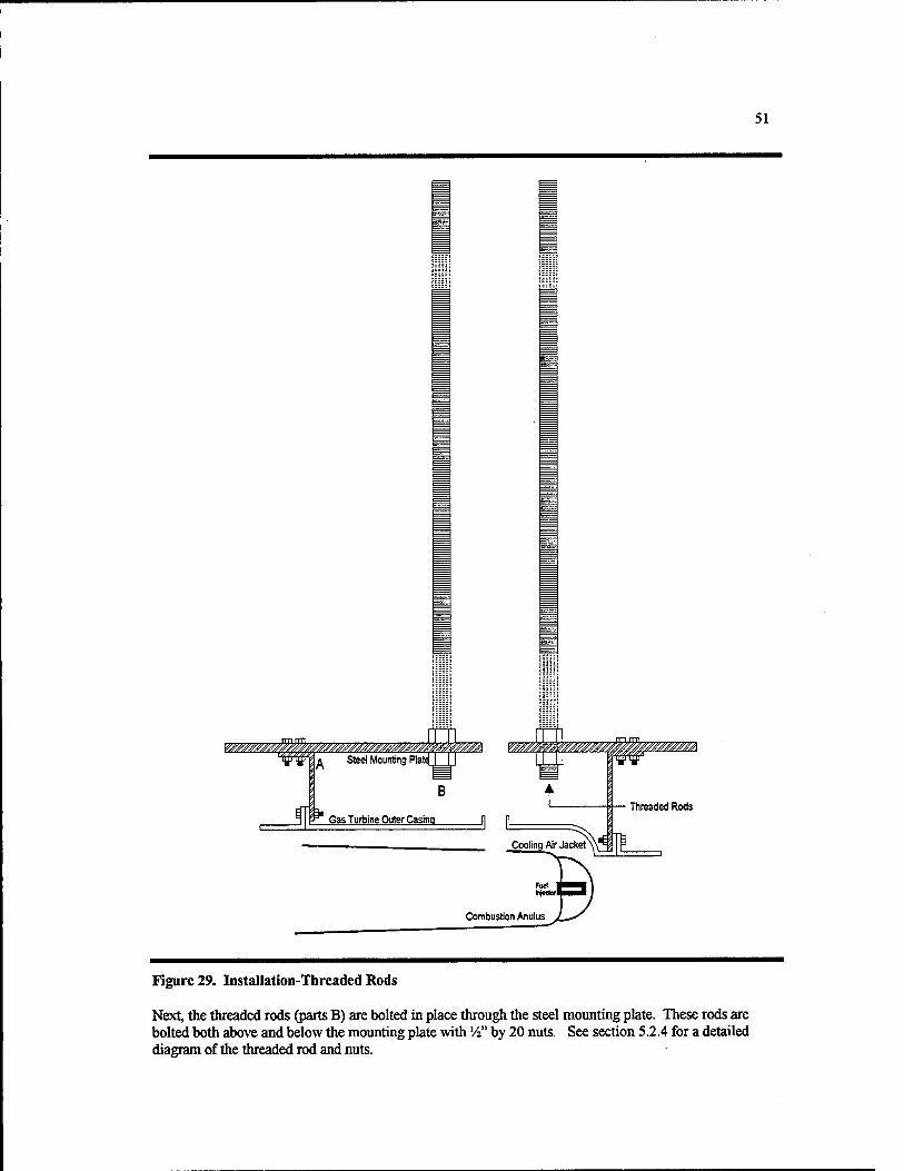
51
Figure 29. Installation-Threaded Rods
Next, the threaded rods (parts B) are bolted in place through the steel mounting plate. These rods are bolted both above and below the mounting plate with '/i" by 20 nuts. See section 5.2.4 for a detailed diagram of the threaded rod and nuts.
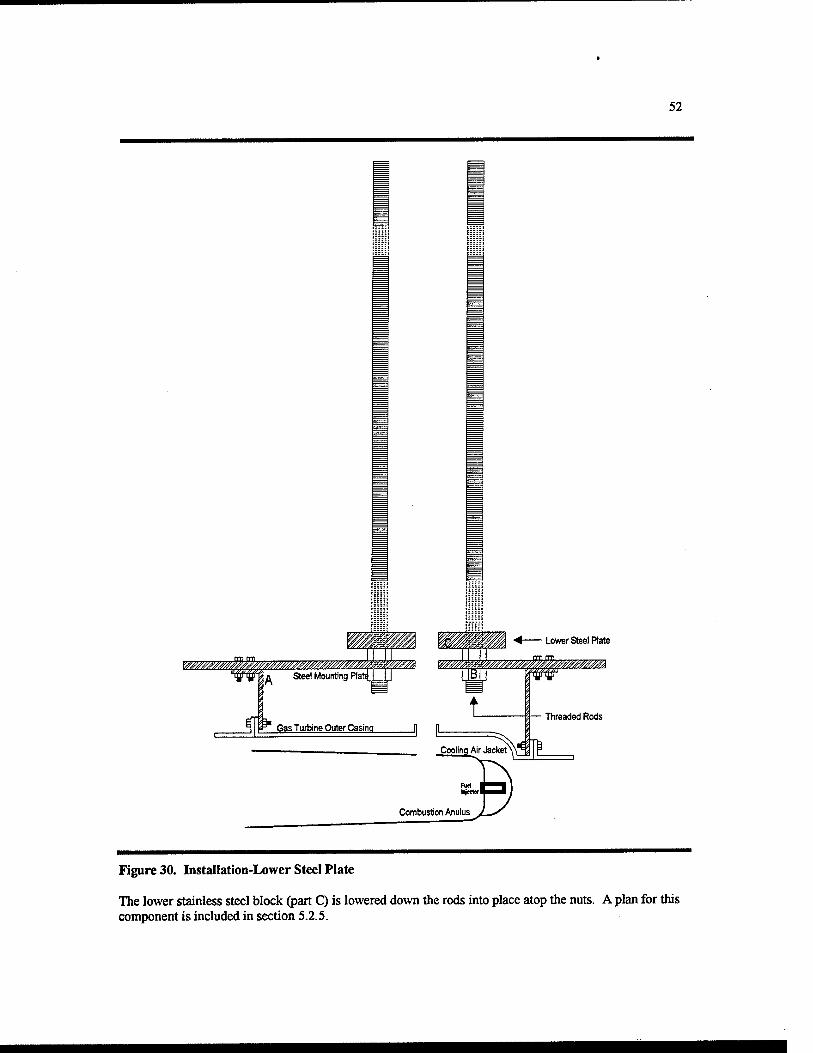
52
Figure 30, Installation-Lower Steel Plate
The lower stainless steel block (part C) is lowered down the rods into place atop the nuts. A plan for this component is included in section 5.2.5.

53
Exhaust Tube—i
Jl
A Steel Mounting Plal
Extraction Tube
Gas Turbine Outer Casing
Gas Tube
Cerannic Blocl<
Lower Steel Plate
Threaded Rods
Figure 31. Installation-Ceramic Block
The ceramic collar is fit onto the lower section of the extraction tube (part E). This collar bolts to the combustor casing of the T-58. The extraction/gas tube seals into the ceramic block (part D) with compressed alumina fiber. The exhaust tube (part N) is similarly sealed into the ceramic Block.
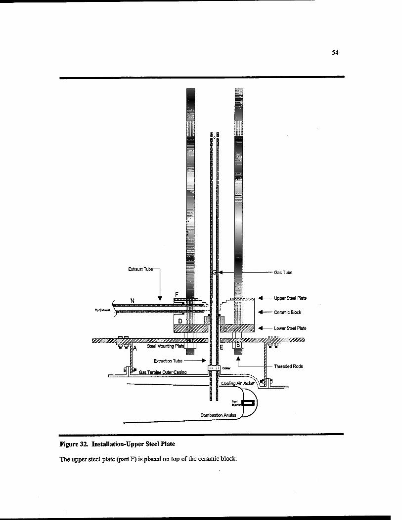
54
Gas Tube
Upper Steel Plate
Ceramic Block
Figure 32. Installation-Upper Steel Plate
The upper steel plate (part F) is placed on top of the ceramic block.
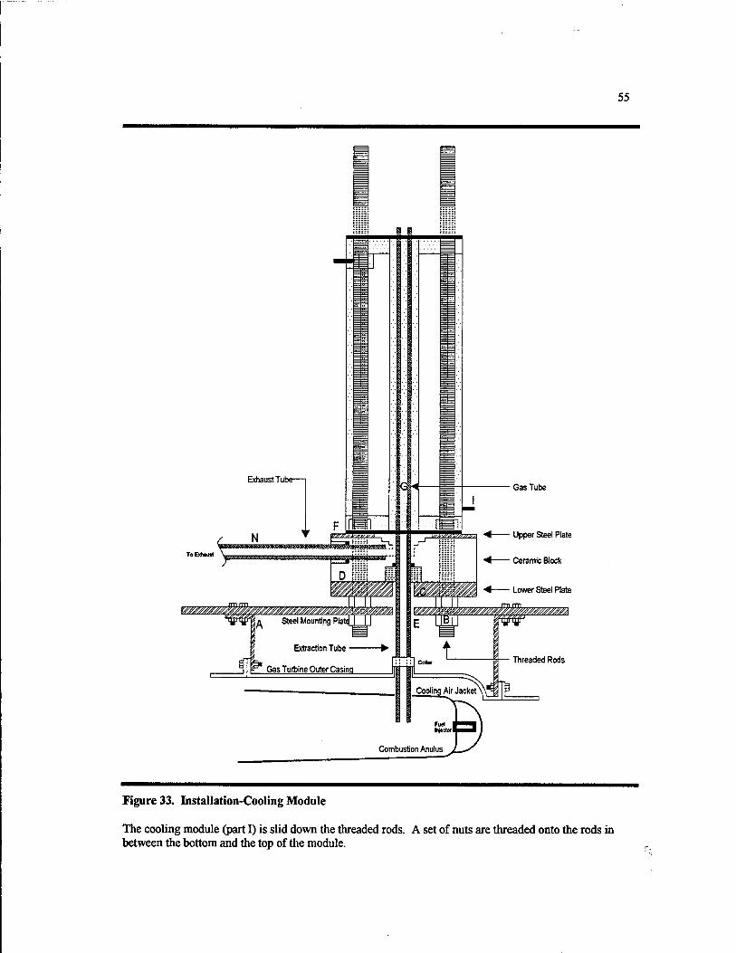
55
Upper Steel Plate
Ceramic Block
Figure 33. Installation-Cooling Module
The cooling module (part I) is slid down the threaded rods. A set of nuts are threaded onto the rods in between the bottom and the top of the module.
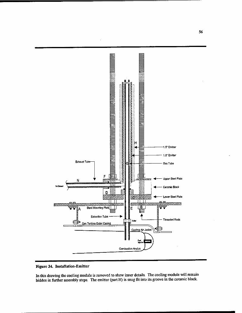
56
Figure 34. Installation-Emitter
In this drawing the cooling module is removed to show inner details. The cooling module will remain hidden in further assembly steps. The emitter (part H) is snug fit into its groove in the ceramic block.
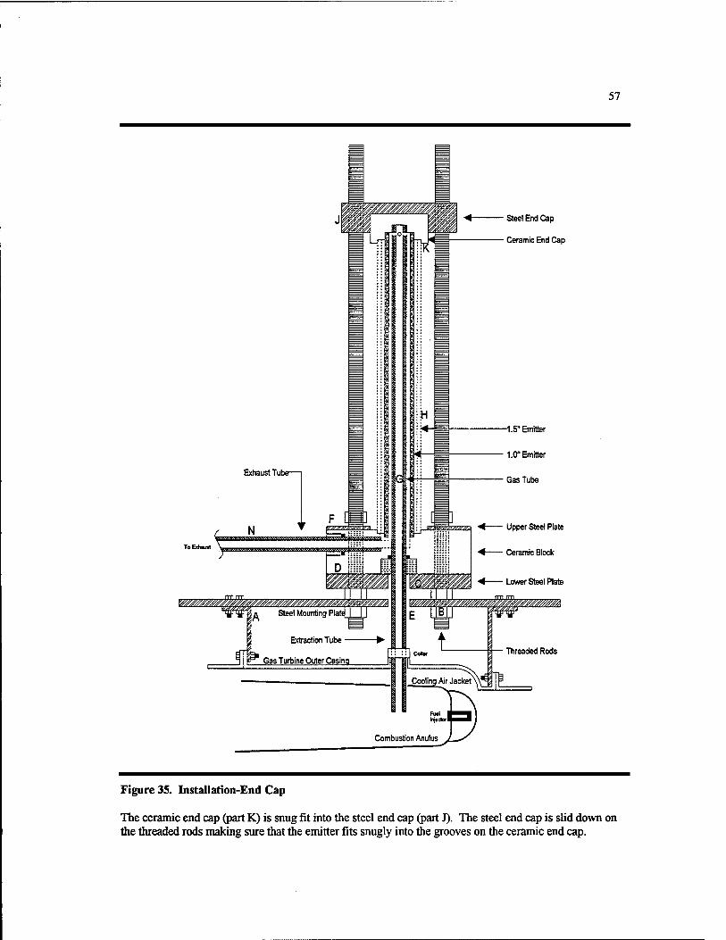
57
' Steel End Cap
' Ceramic End Cap
Figure 35. Installation-End Cap
The ceramic end cap (part K) is snug fit into the steel end cap (part J). The steel end cap is sUd down on the threaded rods making sure that the emitter fits snugly into the grooves on the ceramic end cap.

58
M&R Springs MC12raOf-N
' Steel End Cap
■ Ceramic End Cap
Threaded Rods
Figure 36. Installation-Springs
Four M&R Springs, model MC125Q01-N, (part L) are placed around the threaded rods on top of the steel end cap.
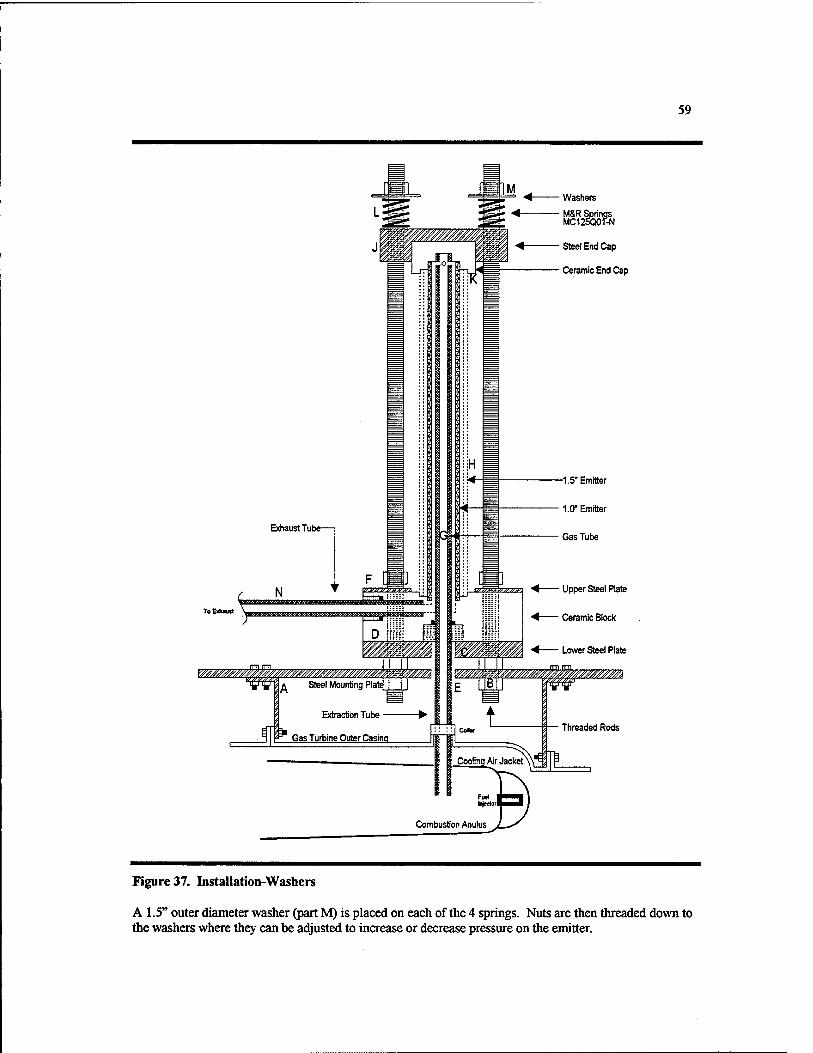
59
■ Washers
• M&R Springs MC12K10f-N
• Steel End Cap
' Ceramic End Cap
-1.5" Emitter
1.0" Emitter
' Upper Steel Plate
' Ceramic Block
Figure 37. Installation-Washers
A 1.5" outer diameter washer (part M) is placed on each of the 4 springs. Nuts are then threaded down to the washers where they can be adjusted to increase or decrease pressure on the emitter.
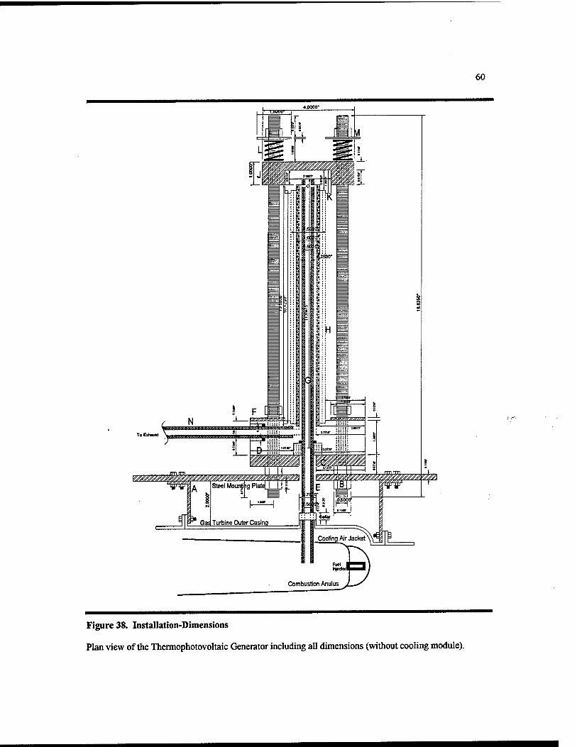
60
Figure 38. Installation-Dimensions
Plan view of the Thermophotovoltaic Generator including all dimensions (without cooling module).

61
Extraction Tube
Gas Turbine Outer Casing
Washers
MSR Springs
Steel End Cap
Ceramic End Cap
Cooling Air Jacket
Connbustion Anulus
' — Threaded Rods
Figure 39. Installation Complete
Plan view of the Thennophotovoltaic Generator including cooling module. Plans for the individual parts are located in section 5.2.

62
5.2 PLAN DRAWINGS FOR INDIVIDUAL COMPONENTS
5.2.1 STEEL MOUNTING PLATE
Figure 40. Mounting plate (top)
Top view of steel mounting plate. The extraction tube passes from the generator into the combustor through the ^-inch hole. Four mounting brackets will hold the plate 2 inches above the combustor outer casing and are bolted to the plate through VJ-inch holes.
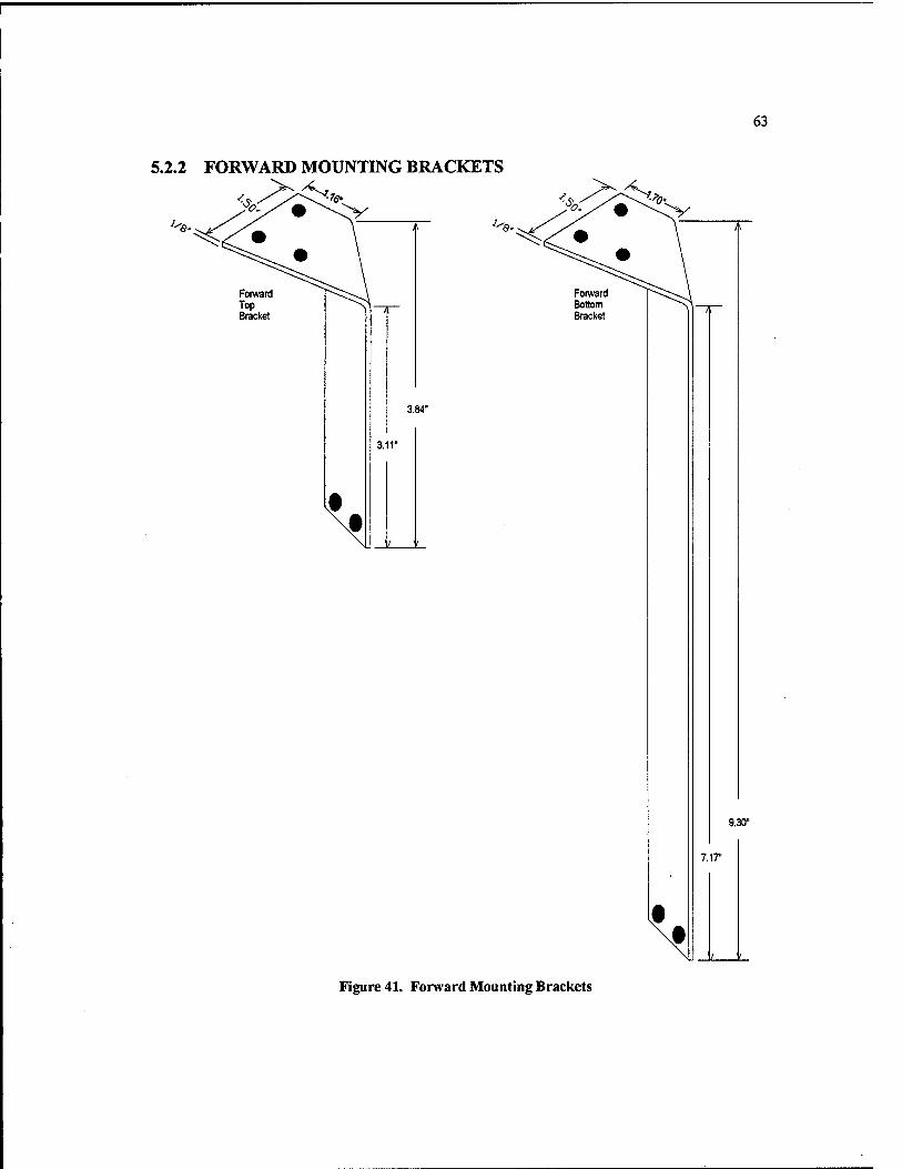
63
5.2.2 FORWARD MOUNTING BRACKETS
Forward Bottom Bracket
9.30"
7.ir
Jz L.
Figure 41. Forward Mounting Brackets
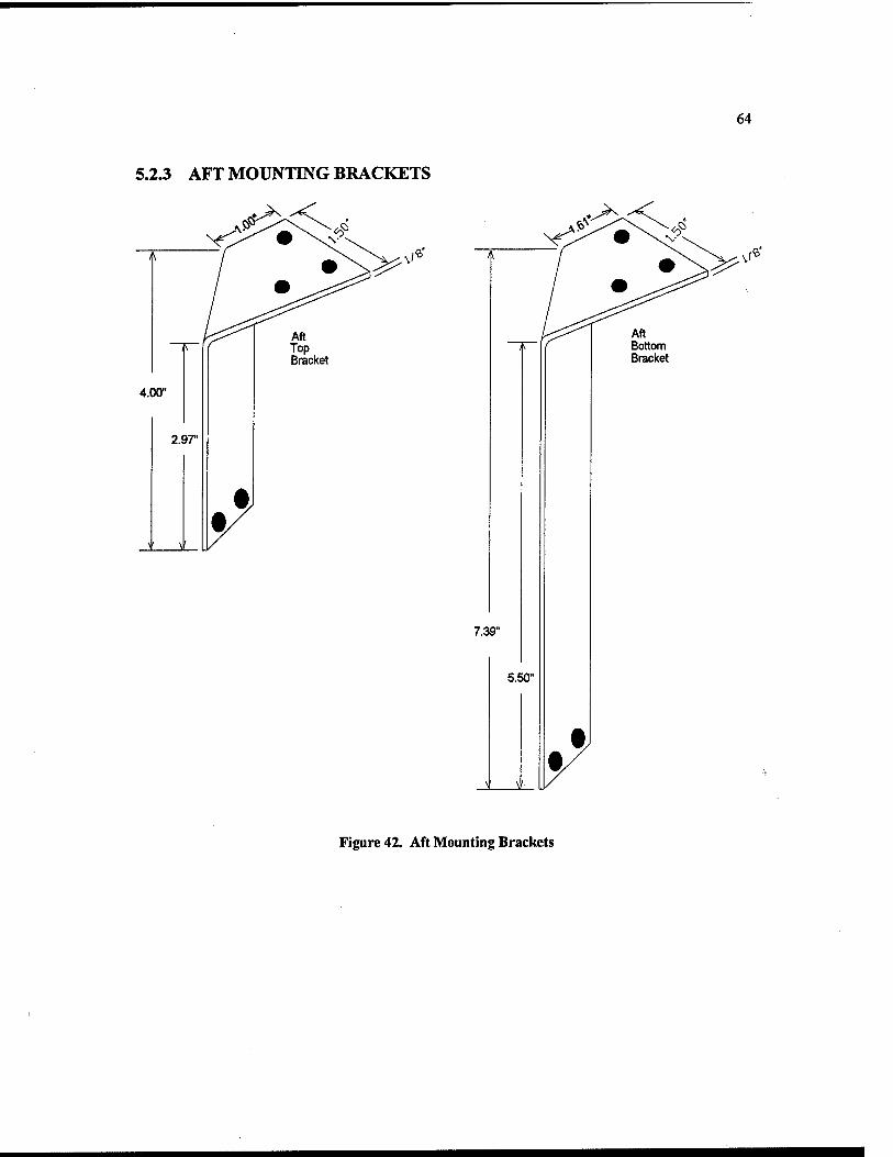
64
5.2.3 AFT MOUNTING BRACKETS
^'^^Xf\
7.39"
5.50"
Aft Bottom Bracket
Figure 42. Aft Mounting Brackets
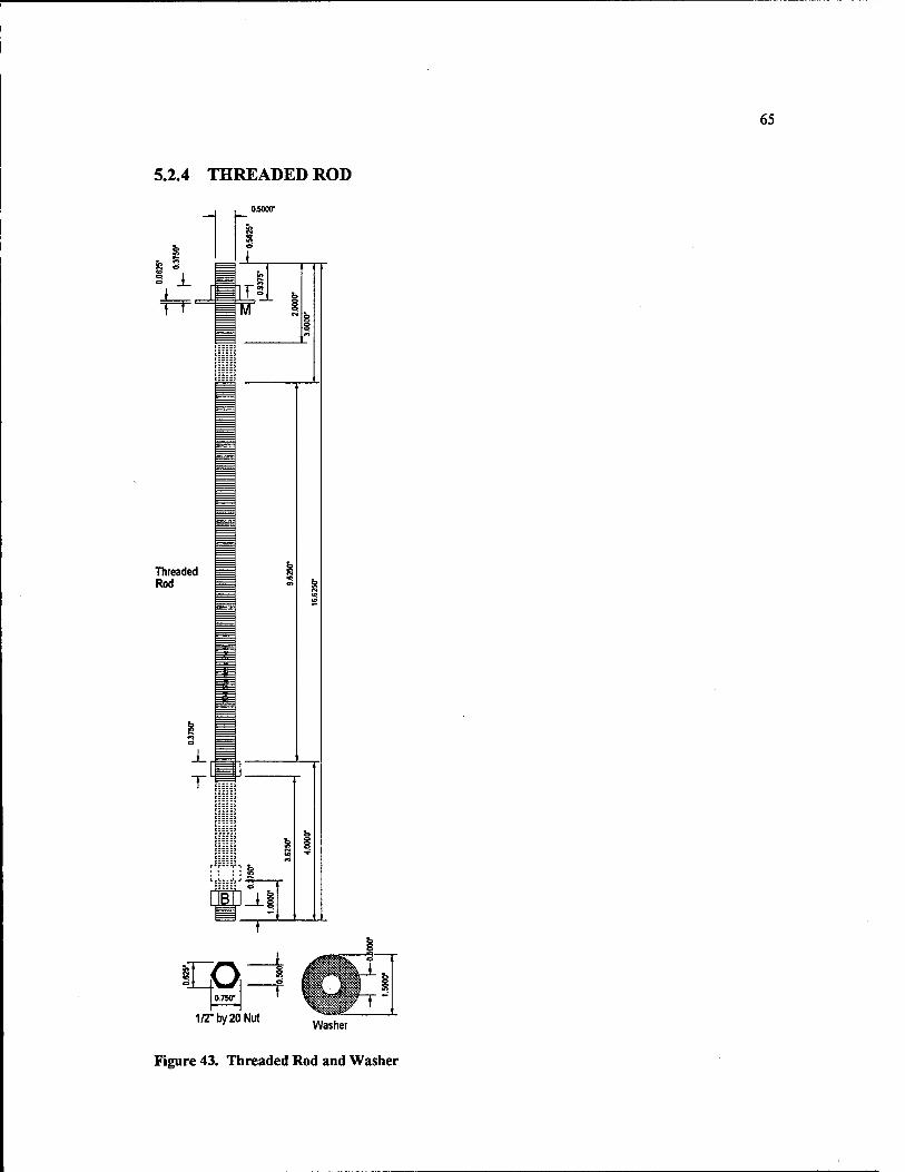
65
5.2.4 THREADED ROD
J_
Threaded Rod
TT^m-jj[
OiOOO"
I0750'
1/2-by20Nut ^^^^^^
Figure 43. Threaded Rod and Washer

5.2.5 STEEL COMPONENTS
66
5.000'
1 r' 1.000'
, 0750'
.^-KT;
^c>~^' '^ i^'-:'? ;^'' 1 1000- ]
5.000'
!■ '1
0,500-, 2.000* 1500- Ho.500f~~
Type 304 Stainless Steel Components
Figure 44. Steel Components

5.2.6 CERAMIC COMPONENTS
67
0.250"
0.750"
Machinable Ceramic Collar
1 1.750"
0.875" ^ 1- 0.250"
T ^ ll 0.250'
5.000"
^^(i jfrwpff^J^TOV^TW^'V
8I0CK innnr I
' ■
Machinable Ceramic Components
Figure 45. Ceramic Components
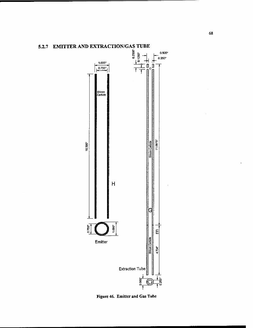
68
5.2.7 EMITTER AND EXTRACTION/GAS TUBE
«S e -^
1.000" ° - '• LL°- [5 -H
0.500"
250"
0.750", tZi^lT
Silicon Carbide
T"
H
Emitter
Extraction Tube
Gi
Figure 46. Emitter and Gas Tube
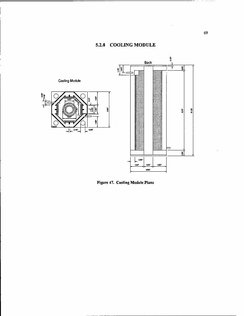
5.2.8 COOLING MODULE
69
Cooling Module
^|_«'=5-^ |_"
Back 1 k 1
— c^ * i ^ ^
=D
i
§
rooo- ^sm■
isxr
Figure 47. Cooling Module Plans

70
6.0 RESULTS AND CONCLUSIONS
6.1 PROJECT RESULTS
The following products were the result of the U.S. Naval Academy Thermophotovoltaic Generator Trident research:
1. A comprehensive design analysis was conducted to meet the criteria for a prototype thermophotovoltaic generator. The Trident report details this design analysis and includes the blueprints for the completed TPV generator. The blueprints contain a step by step assembly of the generator and schematics for all individual components including selected materials.
2. A temperature profile for the T-58 gas turbine combustor was successfully measured. The data collected resulted in a graph that shows the temperature as a function of depth and operating power. This information will be used to determine the optimum placement of the generator's extraction tube.
3. A prototype generator was constructed to the design specifications. Although untested at this juncture, the generator is complete and ready for testing.
6.2 CONCLUSIONS
1. There is a sufficient materials technology base to support continued development of TPV generators that utilize combustion gas. These materials are expensive but are available and are viable solutions to the materials problems encountered with the high temperatures of a TPV generator.
2. The temperature of gas at the ignitor port of a T-58 gas turbine is below 2400°F, rendering it impossible to meet desired temperatures for the generator's emitter, unless combustion continues within the extraction tube.
3. Tapping the turbine combustor downstream could yield the necessary gas temperature to heat the emitter to 2400°F.
4. Thermal shock and oxidation are the primary concerns for selecting a material for use in a hot gas powered TPV generator. High strength is also a major concern for the component that is inserted into the turbine. This piece could cause foreign object damage (FDD) if it structurally failed and was swept into the turbine blades.
71
5. Ceramic composites are the only solution to thermal shock problems encountered with the nearly instantaneous temperature increase during turbine start-up.
6. It is possible to insert a foreign object such as a thermocouple or gas extraction tube into the combustor of a gas turbine without affecting the performance of the engine.
7. A system for the controlled expansion of the emitter and gas tubes is necessary to prevent extremely large compressive stresses. Springs can be used to provide this controlled expansion.

72
REFERENCES
Baldasaro, P.F. et al. "Experimental Assessment of Low Temperature Voltaic Energy Conversion," AIP Conference Proceedings 321: The First NREL Conference on Thermophotovoltaic Generation of Electricity. New York: American Institute of Physics Press, 1994.
Boyce, Meherwan P., Gas Turbine Engineering Handbook. London: Gulf Publishing Company, 1982.
Cengel, Yanus A., and Michael A. Boles. Thermodynamics: An Engineering Approach. New York: McGraw-Hill, Inc., 1994.
Chubb, Donald, and Robert Nelson, "Workshop 3: Emission and Spectral Control," AIP Conference Proceedings 321: The First NREL Conference on Thermophotovoltaic Generation of Electricity. New York: American Institute of Physics Press, 1994.
Cohen, H. et al.. Gas Turbine Theory. New York: John Wiley & Sons, Inc., 1987.
Coutts, Timothy J. and John P. Benner, AIP Conference Proceedings 321: The First NREL Conference on Thermophotovoltaic Generation of Electricity. New York: American Institute of Physics Press, 1994.
Fox, Robert W., and Alan T. McDonald, Introduction to Fluid Mechanics. New York: John Wiley & Sons, 1973.
Fraas, Lewis et al. "Electric Power Production Using New GaSb Photovoltaic Cells with Extended Infrared Response," AIP Conference Proceedings 321: The First NREL Conference on Thermophotovoltaic Generation of Electricity. New York: American Institute of Physics Press, 1994.
lies, Peter A., "Photovohaic Principles Used in Thermophotovoltaic Generators," Aff Conference Proceedings 321: The First NREL Conference on Thermophotovoltaic Generation of Electricity. New York: American Institute of Physics Press, 1994.
Kreith, Frank and Mark Bohn, Principles of Heat Transfer. 5''' ed. St. Paul, Minnesota: West Publishing, 1993.

73
Krist, K., "GRI Research on Thermophotovoltaics," AIP Conference Proceedings 321: The First NREL Conference on Thermophotovoltaic Generation of Electricity. New York: American Institute of Physics Press, 1994.
Larsen, D.C., et al., Ceramic Materials for Advanced Heat Engines. New Jersey: Noyes Publications, 1985.
Lindler, Keith, USNATPV. Vers. 1.0. Computer Software, U.S. Naval Academy, 1995. Quattro Pro® for Windows 5.0 or higher 901K, disk.
Mellor, A.M., Design of Modem Turbine Combustors. London: Harcourt Brace Jovanovich Publishing, 1990
McHenry, Robert, "The Design and Construction of a High Temperature Photon Emitter for a Thermophotovoltaic Generator." Trident Scholar Report. U.S. Naval Academy. May, 1995.
Munson, Bruce et al. Fundamentals of Fluid Mechanics. New York: John Wiley & Sons, 1994.
Musikant, Solomon, What Every Engineer Should Know About Ceramics. New York: Marcel Dekker, 1991.
Noreen, Darryl, and John P. Brermer. "Heat Sources and the Emitting Surfaces," ADP Conference Proceedings 321: The First NREL Conference on Thermophotovohaic Generation of Electricity. New York: American Institute of Physics Press, 1994.
Patterson, Mark. Technology Assessment and Transfer, Annapolis, Maryland. Telephone and Personal Correspondence: 1997.
Quick Beam. Software. Engineering Software Company, Dallas, Texas.
Saxton, Patrick C, "Thermophotovoltaic Emitter Material Selection and Design." Trident Scholar Report. U.S. Naval Academy. May, 1997.
Smith, William F., Foundations of Materials Science and Engineering. New York: McGraw Hill, 1993.
The Temperature Handbook. Stamford, Connecticut: Omega Engineering Inc., 1995.

74
Trefilov, V.I., Ceramic- and Carbon-Matrix Composites. London: Chapman & Hall, 1995.
Wanlass, M.W., and RJ. Schwartz, "Introduction to Workshop on Spectral Control and Converters," AIP Conference Proceedings 321: The First NREL Conference on Thermophotovoltaic Generation of Electricity. New York: American Institute of Physics Press, 1994.
75
APPENDICES
A. ANALYSIS OF GAS FLOW EFFECTS ON EXTRACTION TUBE 76 B. MATERIALS TESTING 82 C. RADIATION SHAPE FACTORS 86
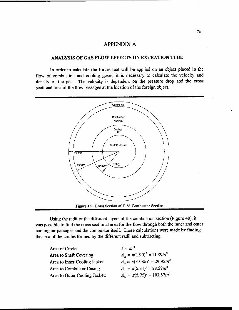
76
APPENDIX A
ANALYSIS OF GAS FLOW EFFECTS ON EXTRATION TUBE
In order to calculate the forces that will be applied on an object placed in the flow of combustion and cooling gases, it is necessary to calculate the velocity ^nd density of the gas. The velocity is dependent on the pressure drop and the cross sectional area of the flow passages at the location of the foreign object.
Figure 48. Cross Section of T-58 Combustor Section
Using the radii of the different layers of the combustion section (Figure 48), it was possible to find the cross sectional area for the flow through both the inner and outer cooling air passages and the combustor itself These calculations were made by finding the area of the circles formed by the different radii and subtracting.
Area of Circle: Area to Shaft Covering:
Area to Inner Cooling jacket:
Area to Combustor Casing:
Area to Outer Cooling Jacket:
4 = ;<3.086)'=29.92/«'
^,, = ;<5.31)'=88.58/«'
^«. = ^5.75)' = 103.87/w'

77
Component areas:
Combustor Area: Aor^us^r =A„- 4. = 88.58 - 29.92 = 58.66 in^
Cooling Jacket Area: A^,„^ = Ac -4..*««o. "^^ = 103.87-58.66-11.39 = 33.82 in'
C! Cooling Jacket 0.444"
Extraction Tube
Combustion Chamber
2.306"
2 3/4"
Figure 49. Maximum Extraction Tube dimensions
Velocity calculations:
Constants:
From T-58F Technical Manual -^^ lb ,^^^ lb
mair = 656 = 10.93 — min sec
TtlCombustor = 0. 25/Wm> • •
mjacket = O.lSniair
Pconi>ustor='^^^PSia
T;^, = 5SrF=l041.6TR
Tc„^.,=3500'F=3959.6rR
Gas Laws (Cengel, 1994) psiaft^
/? = 0.3704^ lbm°R
Pv = RT
m = pAV

78
Compute density:
P 1 P Pv = RT=>-^ = -^-— = p
RT V RT
^^, = ^ = ^^^ = 0.3058^^ Px
7Siaft^
Ibm^R
(0.3704 ^^Pi^)(1041.67°i?) Ibm- R
p =.^^ = \\^t^ = 0.0791
RTc (0.3704^^'^/ )(3959.67°) ^^
Compute velocity:
mcombustor = 0.25 niair =^ Pc^cK:
—) = (0.0791-^)(58.662/«')(-i^' sec /r' ^144zV
ft
mcc^ustor = 0.25(10.93-^) = (0.0791^(58.662/«')(—=^)Fc
'^Combustor ~ °^- ° „ ^ sec
m Jacket = 0.15m air = PjAjVj
mjacket = 0.75(10.93—) = (0.3058-^)(33.812/«')(-i^)F, sec // 144zw
V =1142— '^Jacket - ^^^•''„„„ sec
Viscosity calculations: The viscosity for air is not published for temperatures as high as 3500 degrees. The value of the dynamic viscosity was calculated using the equation:
3
p = -^ (Fox, 1973)
where b and s are unitless constants for the fluid. These constants must be solved for air utilizing known values of the dynamic viscosity.
Pick 2 Points: T=273°K n=17.456xl0-^ T=1273°K n=48.445xl0"^

79
Substitute both points into equation:
7.456xlO- = *P^ 48.445 X10-«=»^'S' 5+273 5+1273
5+273 = *(258403987.2) 5 + 1273 = ft(937548288.2)
s = 107.48 b = 0.000000147
Solve dynamic viscosity {\x) in combustor and cooling jacket:
Combustor Cooling Jacket 3
_ Z>(3960)^ _ Z>(1042)^ Mcc^stor - ^^395Q ^J'-clce, " ^ + 1042
ft-s ft-s
Compute the Reynolds Numbers:
Re,=^^ Re,=^^
(0.079 A)(84.8^)(0.0425//) (0.3058^)(114.15-^)(0.0425/0 ft sec T> _ /' sec
Re^ - „ Re^ - „ 9.006x10-*-^^ 4.301 xlO""-^^
ft-s ft-s
Rec= 31650.051 = 3.1x10^ Re^ =344931.52 = 3.4x10'
The coefficient of drag for a tube is tabulated by the Reynold's number (Munson, 1994). The Reynolds numbers determined the following values for the drag coefficient:
C^^=1.2 Q,=1.0
The coefficient of drag is defined by the equation:
C = ^°"=^ =>£) =r —oTPhD -pU^bD 2

80
The drag per unit length is calculated with the above equation. It is necessary to find the drag per length in order to calculate the bending moment on the drawing tube.
Drag Force:
Combustion Section
^ = C^ ^pU'D = (1.2)(^)(0.0791^)(84.8£)^(0.0425/0(^^^^^) = 0.451^
Dforce = ^* = 0.451-^(0.179/0 = 0.081/^>^
Cooling Jacket Section:
^ = C,^pU'D = (104)(0-3058^)(114.5£)^(0.0425//)(^^1^) = 2.648^
Dporce = ^^* = 2.648^(0.037//) = 0.098/Z>^ b jt
These forces act on the surfaces as indicated in Figure 50. The force per unit length was necessary as the force acts evenly across each respective section of the drawing tube.
The force per unit length was entered into the computer program Quick Beam, treating the drawing tube as a cantilever supported at the base plate, where it intersects the outer turbine casing. The force acting at the base was calculated as 0.1846 Ibf With a cross sectional area of 0.094 in^, this creates a shear stress in the base of the tube of 1.97 psi. For the worst case scenario, it was assumed that all forces acted at a single point. The force acting on the base would then be 2.73 Ibf, for a total shear stress of 29.1 psi, well within the safe operating limits of the material.
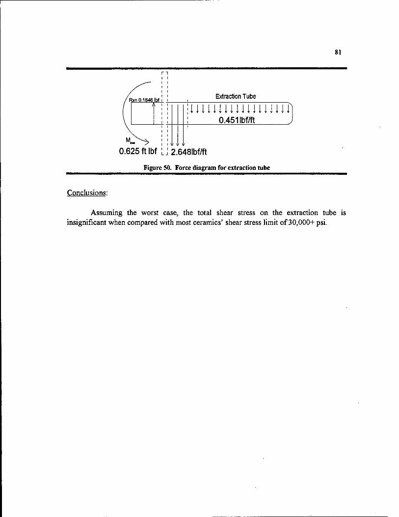
SI
n
Rxn 0.1846 Ibf Extraction Tube
0.625 ft Ibf LJ
0.451 Ibf/ft
2.648lbf/ft
Figure 50. Force diagram for extraction tube
Conclusions:
Assuming the worst case, the total shear stress on the extraction tube is insignificant when compared with most ceramics' shear stress limit of 30,000+ psi.
82
APPENDIX B
MATERIALS TESTING
PURPOSE:
The material Omegatite 450 was tested for durability and suitability for use in a thermophotovoltaic generator at high temperatures. This product is designed for use at extremely high temperatures. Commercially, it is used to shield thermocouples. For the current project, it was to be used as an extraction tube to draw hot combustion gases from the inside of a gas turbine. Omegatite was selected because it was designed to handle temperatures in excess of 4000°F, had enough shear strength to withstand the force of flowing combustion gas, and had an extremely low thermal conductivity.
Tests were conducted to qualitatively simulate the environment inside the combustion chamber of a T-58 gas turbine by placing the samples of Omegatite in the flame of an acetylene torch and heating them evenly until fracture. The initial samples used were shards of Omegatite 450 from a broken tube. Then a portion of the tube was tested, as was a capped end section of tube. Tubes of different wall thickness were also tried, as well as the almost solid, commercially available thermocouple sheath.
PROCEDURE AND DATA.
Test 1: Two shards were heated as read by thermocouple probe at 540°C, until they radiated their own light. These shards were to be quenched in 0.2°C degree water. However, after heating, both shards showed signs of cracking. Both shards fractured into 3 pieces when moved with tongs. The pieces that remained in the tongs were quenched. These quenched pieces fragmented into many smaller pieces. The quenched Omegatite, when removed from the water, was whiter in color, and crumbled easily in hand. Such adverse reaction to thermal shock made further, more quantitative testing necessary.
Test 2: A sample of a '/2-inch outer diameter, 3/8-inch inner diameter Omegatite 450 tube was heated in the same manner as in Test 1. The top portion of the tube (standing on end) was heated evenly until it glowed red hot. The bottom of this tube did not glow, indicating the extremely poor thermal conductivity of this material. Upon reaching a stay of radiance, cracks in the material became evident. Although visible, these cracks did not cause the material to fracture. However, after cooling, these cracks were still visible.
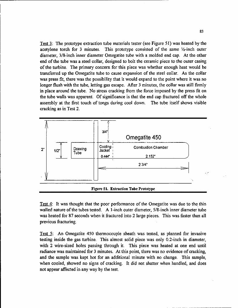
83
Test 3: The prototype extraction tube materials tester (see Figure 51) was heated by the acetylene torch for 3 minutes. This prototype consisted of the same '/4-inch outer diameter, 3/8-inch inner diameter Omegatite tube with a molded end cap. At the other end of the tube was a steel collar, designed to bolt the ceramic piece to the outer casing of the turbine. The primary concern for this piece was whether enough heat would be transferred up the Omegatite tube to cause expansion of the steel collar. As the collar was press fit, there was the possibility that it would expand to the point where it was no longer flush with the tube, letting gas escape. After 3 minutes, the collar was still firmly in place around the tube. No stress cracking fi-om the force imposed by the press fit on the tube walls was apparent. Of significance is that the end cap fi^actured off the whole assembly at the first touch of tongs during cool down. The tube itself shows visible cracking as in Test 2.
I\
2" 1/2" Drawing Tube
\l
3/4*
Cooling i Jacl<et I
0.444" I
Omegatite 450
Combustion Chamber
2.152"
2 3/4"
Figure 51. Extraction Tube Prototype
Test 4: It was thought that the poor performance of the Omegatite was due to the thin walled nature of the tubes tested. A 1-inch outer diameter, 5/8-inch inner diameter tube was heated for 87 seconds when it fractured into 2 large pieces. This was faster than all previous fi-acturing.
Test 5: An Omegatite 450 thermocouple sheath was tested, as planned for invasive testing inside the gas turbine. This almost solid piece was only 0.2-inch in diameter, with 2 wire-sized holes passing through it. This piece was heated at one end until radiance was maintained for 3 minutes. At this point, there was no evidence of cracking, and the sample was kept hot for an additional minute with no change. This sample, when cooled, showed no signs of cracking. It did not shatter when handled, and does not appear affected in any way by the test.
84
Test 6: To test for flaws present in the material, a '/2-inch outer diameter, V^-inch inner diameter tube, uncut, was passed in the flame for 5 seconds to get a slightly red glow. Five seconds was enough time to clearly see cracking in the material. After cooling, these cracks were still visible.
DISCUSSION:
These tests were in some ways spurred on because of an accident. The first Omegatite tube was taken to the Technical Support Division Shop, to be cut into smaller sample pieces. The cut tube shattered when subjected to a slight impact. The nature of the impact should not have caused the fi-acture at all. It was necessary to perform these tests to see that the cracks causing the material to fail were always in the material, just not necessarily visible.
The first test only proved that the material had obvious structural changes occurring at high temperature. The second test showed the cracks both during heating and after cooling that would be seen in all further samples except for the thermocouple sheath. The cracks apparent on the second sample corresponded with the jagged edges around the top of the tube from the accidental fi-acture. There is the possibility that these cracks were either always present, or developed in the material during cutting. The possibility was fiirther illustrated by the failure of the prototype invasive materials tester, which showed cracking immediately and later fractured along one of these cracks. Through this test, all samples had come from the same tube, which could have been manufactured pooriy, or was unique in some other unknown way. A large piece was heated and immediately showed the cracking. Under heating conditions, the large piece fractured, without any physical pressure being applied. However, the large piece had also been cut. An uncut sample was tested to determine the extent of damage caused by the cutting action. An uncut, '/2-inch outer diameter, '/i-inch inner diameter tube was passed through the flame until cherry red. This small amount of heating left the same pattern of cracking visible on the tube. This eliminated the possibility that cutting affecting the structural integrity of the Omegatite. Lastly, a thermocouple sheath was heated. It did not show any signs of cracking, nor did it become brittle and fracture. This is most likely due to the piece's very small size, or else the piece was manufactured by a different process than the tubes that does not leave large invisible flaws in the material. For the tubes, the flaws appeared immediately. They did not have the time to form as in Test 6.
There is also the possibility that the larger samples cracked because of uneven heating. The smaller thermocouple sheath would quickly reach a uniform temperature, while the larger tubes have a substantial thermal gradient across the tube walls. The
85
varying temperatures would cause varying degrees of thermal expansion, causing thermal shock. Thermal shock or manufacturing flaws could have been the cause of the material fracture.
CONCLUSIONS:
The Omegatite 450 does withstand the temperatures for which it is designed but is subject to fracture because of the propagation of cracks already present in the material and extensive thermal shock. Internal flaws are a trademark of all ceramics and would cause the immediate crack appearance seen in this material. These flaws however, render the Omegatite 450 unusable in the gas turbine as an extraction tube as the slightest vibration could send fragments into the engine. The thermocouple sheath is capable of withstanding the high temperatures and ftmction normally. It is strong enough to be used as the sheath protecting thermocouples used to measure gas temperature inside the combustion chamber of the T-58 gas turbine.

86
APPENDIX C
RADIATION SHAPE FACTORS
The TPV generator converts radiant thermal energy into electricity using thermophotovoltaic cells. These cells face a radiant emitter that emits the thermal radiation necessary for electrical power generation. However, these cells do not completely surround the emitter tube. Areas without cells reflect the thermal energy back to the emitter tube using gold foil. The reflectivity of the gold foil and that of the spectral filters on the cells is different. Because materials testing showed problems with thermal shock for ceramics, there was concern that a circumferential temperature gradient might also cause a thermal shock failure. The radiation shape factors were calculated and used in a spreadsheet to model the circumferential temperature profile.
Cells
Figure S2. Shape Factor (foil)
The geometry of emitter and cell array determines the radiation shape factor. The bottom set of cells has been omitted for clarity. This diagram shows the geometry for radiation leaving the emitter and striking the gold foil.
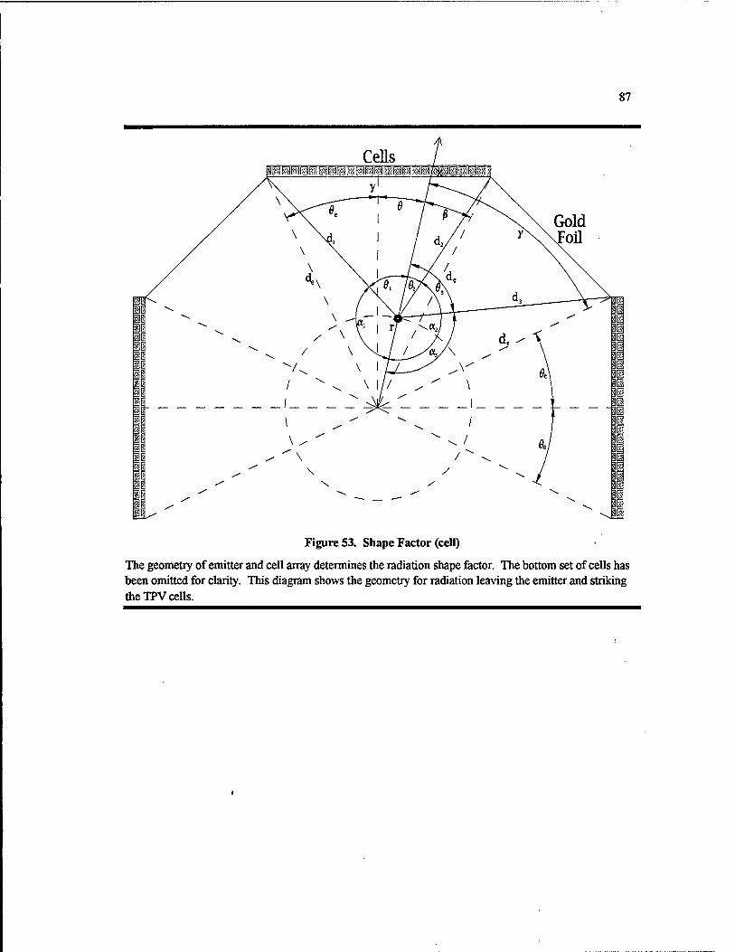
87
Gold Foil
Figure S3. Shape Factor (cell)
The geometry of emitter and cell array determines the radiation shape factor. The bottom set of cells has been omitted for clarity. This diagram shows the geometry for radiation leaving the emitter and striking the TPV cells.
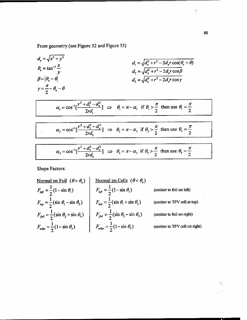
From geometry (see Figure 52 and Figure 53)
88
^ =tan-'- y
dx = -^d] +r^- Id/ cos(^, + 6)
d^=^dl+r''-2d/co&p
di = yjd^ +r^- 2d/ cos y
.,y+d^-di. 71 TC 0^ = n- a, if ^] > — then use ^, = —
7t 7t 6, = n- a, if ^, > — then use 9.= —
_,j^^d\-d]. 71 7V 6. = 7t- a, if ^, > — then use ft = —
Shape Factors:
Normal on Foil {6> 6^)
'P;<,;,=-(sJn^,-sin^2)
Normal on Cells {6<9^)
i^,_,=l(l-sin0,) 2 j_ 2
1
^o;,=r(sin^i+sin^2)
(emitter to foil on left)
(emitter to TPV cell at top)
(emitter to foil on right)
(emitter to TPV cell on right)
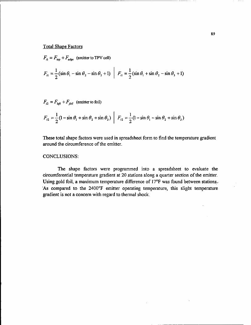
89
Total Shape Factors
i=;, = F^^ + F^^^^ (emitter to TPV cell)
iv, = —(sin 6^ - sin 6^ - sin ^3 +1) ivi = — (sin 0^ + sin 6^ - sin 6^ +1)
^2 = ^te/j + -^/o./ (emitter to foil)
i^2 = —(1 - sin ^1 + sin ^2 + sin 0^) Fj2 = —(} - sin ^1 - sin 9^ + sin ^3)
These total shape factors were used in spreadsheet form to find the temperature gradient around the circumference of the emitter.
CONCLUSIONS:
The shape factors were programmed into a spreadsheet to evaluate the circumferential temperature gradient at 20 stations along a quarter section of the emitter. Using gold foil, a maximum temperature difference of 17°F was found between stations.- As compared to the 2400°F emitter operating temperature, this slight temperature gradient is not a concern with regard to thermal shock.