Embed Size (px)
Citation preview
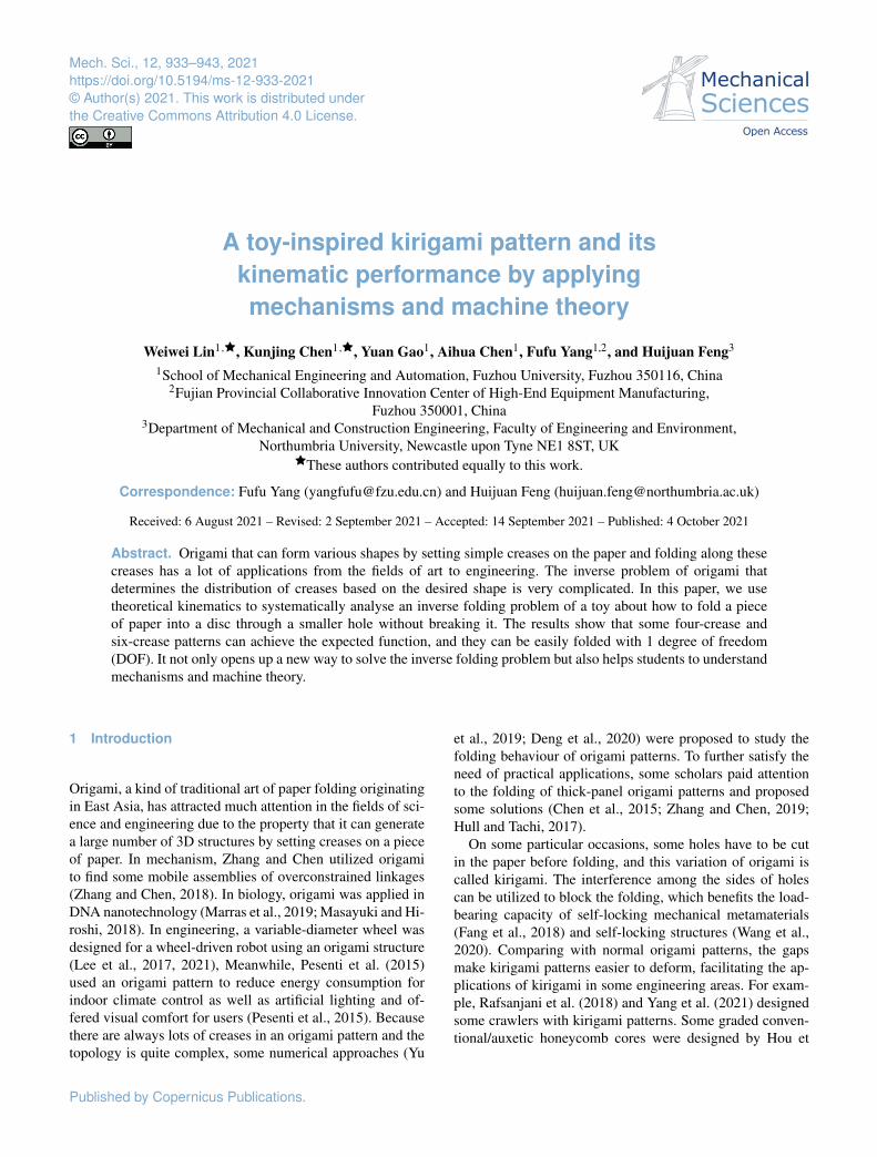
Mech. Sci., 12, 933–943, 2021https://doi.org/10.5194/ms-12-933-2021© Author(s) 2021. This work is distributed underthe Creative Commons Attribution 4.0 License.
A toy-inspired kirigami pattern and itskinematic performance by applyingmechanisms and machine theory
Weiwei Lin1,�, Kunjing Chen1,�, Yuan Gao1, Aihua Chen1, Fufu Yang1,2, and Huijuan Feng3
1School of Mechanical Engineering and Automation, Fuzhou University, Fuzhou 350116, China2Fujian Provincial Collaborative Innovation Center of High-End Equipment Manufacturing,
Fuzhou 350001, China3Department of Mechanical and Construction Engineering, Faculty of Engineering and Environment,
Northumbria University, Newcastle upon Tyne NE1 8ST, UK�These authors contributed equally to this work.
Correspondence: Fufu Yang ([email protected]) and Huijuan Feng ([email protected])
Received: 6 August 2021 – Revised: 2 September 2021 – Accepted: 14 September 2021 – Published: 4 October 2021
Abstract. Origami that can form various shapes by setting simple creases on the paper and folding along thesecreases has a lot of applications from the fields of art to engineering. The inverse problem of origami thatdetermines the distribution of creases based on the desired shape is very complicated. In this paper, we usetheoretical kinematics to systematically analyse an inverse folding problem of a toy about how to fold a pieceof paper into a disc through a smaller hole without breaking it. The results show that some four-crease andsix-crease patterns can achieve the expected function, and they can be easily folded with 1 degree of freedom(DOF). It not only opens up a new way to solve the inverse folding problem but also helps students to understandmechanisms and machine theory.
1 Introduction
Origami, a kind of traditional art of paper folding originatingin East Asia, has attracted much attention in the fields of sci-ence and engineering due to the property that it can generatea large number of 3D structures by setting creases on a pieceof paper. In mechanism, Zhang and Chen utilized origamito find some mobile assemblies of overconstrained linkages(Zhang and Chen, 2018). In biology, origami was applied inDNA nanotechnology (Marras et al., 2019; Masayuki and Hi-roshi, 2018). In engineering, a variable-diameter wheel wasdesigned for a wheel-driven robot using an origami structure(Lee et al., 2017, 2021), Meanwhile, Pesenti et al. (2015)used an origami pattern to reduce energy consumption forindoor climate control as well as artificial lighting and of-fered visual comfort for users (Pesenti et al., 2015). Becausethere are always lots of creases in an origami pattern and thetopology is quite complex, some numerical approaches (Yu
et al., 2019; Deng et al., 2020) were proposed to study thefolding behaviour of origami patterns. To further satisfy theneed of practical applications, some scholars paid attentionto the folding of thick-panel origami patterns and proposedsome solutions (Chen et al., 2015; Zhang and Chen, 2019;Hull and Tachi, 2017).
On some particular occasions, some holes have to be cutin the paper before folding, and this variation of origami iscalled kirigami. The interference among the sides of holescan be utilized to block the folding, which benefits the load-bearing capacity of self-locking mechanical metamaterials(Fang et al., 2018) and self-locking structures (Wang et al.,2020). Comparing with normal origami patterns, the gapsmake kirigami patterns easier to deform, facilitating the ap-plications of kirigami in some engineering areas. For exam-ple, Rafsanjani et al. (2018) and Yang et al. (2021) designedsome crawlers with kirigami patterns. Some graded conven-tional/auxetic honeycomb cores were designed by Hou et
Published by Copernicus Publications.
934 W. Lin et al.: A toy-inspired kirigami pattern and its kinematic performance
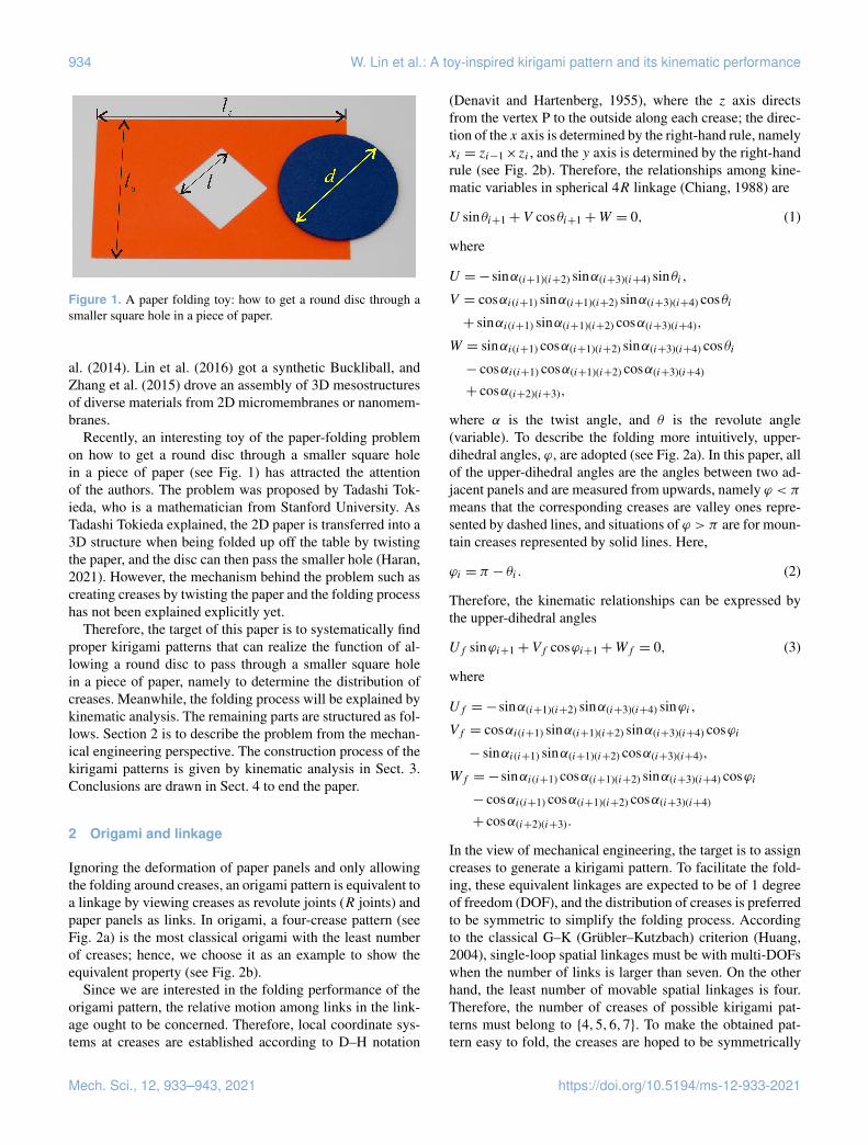
Figure 1. A paper folding toy: how to get a round disc through asmaller square hole in a piece of paper.
al. (2014). Lin et al. (2016) got a synthetic Buckliball, andZhang et al. (2015) drove an assembly of 3D mesostructuresof diverse materials from 2D micromembranes or nanomem-branes.
Recently, an interesting toy of the paper-folding problemon how to get a round disc through a smaller square holein a piece of paper (see Fig. 1) has attracted the attentionof the authors. The problem was proposed by Tadashi Tok-ieda, who is a mathematician from Stanford University. AsTadashi Tokieda explained, the 2D paper is transferred into a3D structure when being folded up off the table by twistingthe paper, and the disc can then pass the smaller hole (Haran,2021). However, the mechanism behind the problem such ascreating creases by twisting the paper and the folding processhas not been explained explicitly yet.
Therefore, the target of this paper is to systematically findproper kirigami patterns that can realize the function of al-lowing a round disc to pass through a smaller square holein a piece of paper, namely to determine the distribution ofcreases. Meanwhile, the folding process will be explained bykinematic analysis. The remaining parts are structured as fol-lows. Section 2 is to describe the problem from the mechan-ical engineering perspective. The construction process of thekirigami patterns is given by kinematic analysis in Sect. 3.Conclusions are drawn in Sect. 4 to end the paper.
2 Origami and linkage
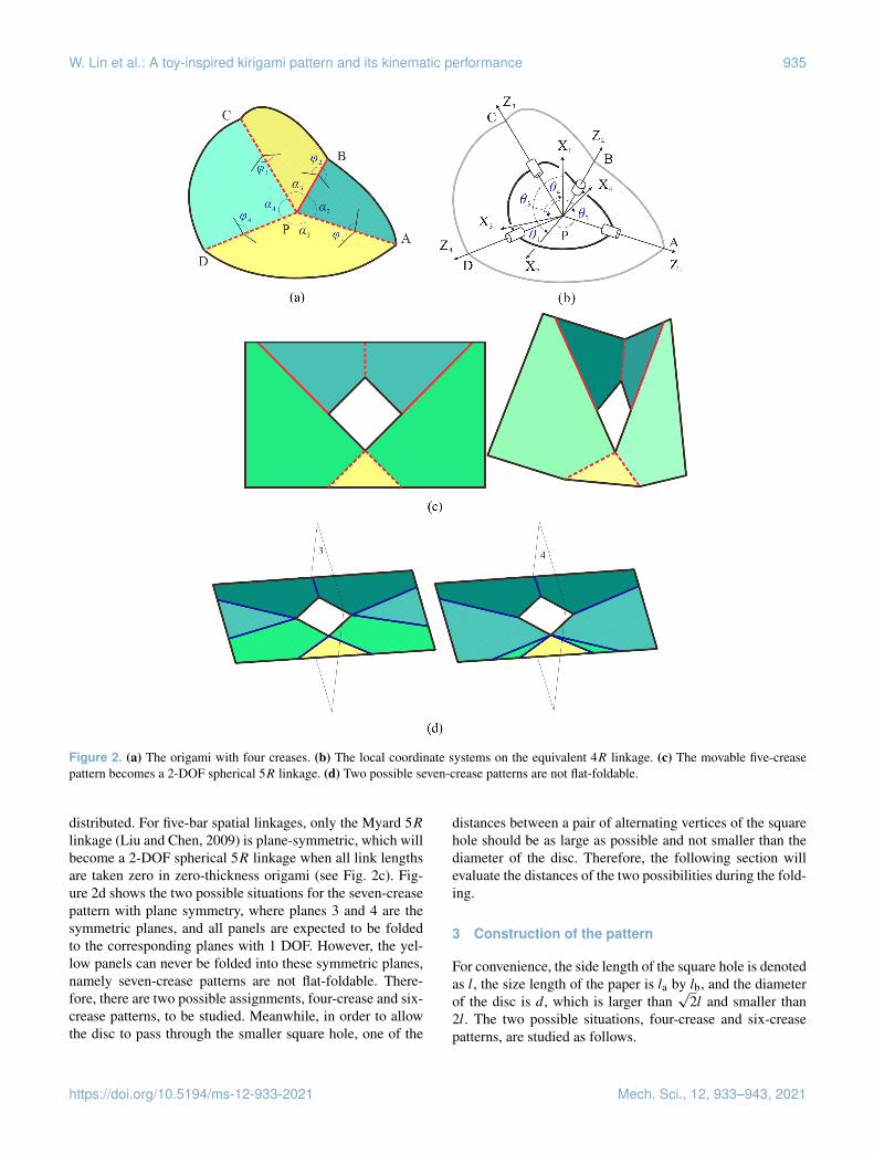
Ignoring the deformation of paper panels and only allowingthe folding around creases, an origami pattern is equivalent toa linkage by viewing creases as revolute joints (R joints) andpaper panels as links. In origami, a four-crease pattern (seeFig. 2a) is the most classical origami with the least numberof creases; hence, we choose it as an example to show theequivalent property (see Fig. 2b).
Since we are interested in the folding performance of theorigami pattern, the relative motion among links in the link-age ought to be concerned. Therefore, local coordinate sys-tems at creases are established according to D–H notation
(Denavit and Hartenberg, 1955), where the z axis directsfrom the vertex P to the outside along each crease; the direc-tion of the x axis is determined by the right-hand rule, namelyxi = zi−1×zi , and the y axis is determined by the right-handrule (see Fig. 2b). Therefore, the relationships among kine-matic variables in spherical 4R linkage (Chiang, 1988) are
U sinθi+1+V cosθi+1+W = 0, (1)
where
U =−sinα(i+1)(i+2) sinα(i+3)(i+4) sinθi,
V = cosαi(i+1) sinα(i+1)(i+2) sinα(i+3)(i+4) cosθi+ sinαi(i+1) sinα(i+1)(i+2) cosα(i+3)(i+4),
W = sinαi(i+1) cosα(i+1)(i+2) sinα(i+3)(i+4) cosθi− cosαi(i+1) cosα(i+1)(i+2) cosα(i+3)(i+4)
+ cosα(i+2)(i+3),
where α is the twist angle, and θ is the revolute angle(variable). To describe the folding more intuitively, upper-dihedral angles, ϕ, are adopted (see Fig. 2a). In this paper, allof the upper-dihedral angles are the angles between two ad-jacent panels and are measured from upwards, namely ϕ < πmeans that the corresponding creases are valley ones repre-sented by dashed lines, and situations of ϕ > π are for moun-tain creases represented by solid lines. Here,
ϕi = π − θi . (2)
Therefore, the kinematic relationships can be expressed bythe upper-dihedral angles
Uf sinϕi+1+Vf cosϕi+1+Wf = 0, (3)
where
Uf =−sinα(i+1)(i+2) sinα(i+3)(i+4) sinϕi,
Vf = cosαi(i+1) sinα(i+1)(i+2) sinα(i+3)(i+4) cosϕi− sinαi(i+1) sinα(i+1)(i+2) cosα(i+3)(i+4),
Wf =−sinαi(i+1) cosα(i+1)(i+2) sinα(i+3)(i+4) cosϕi− cosαi(i+1) cosα(i+1)(i+2) cosα(i+3)(i+4)
+ cosα(i+2)(i+3).
In the view of mechanical engineering, the target is to assigncreases to generate a kirigami pattern. To facilitate the fold-ing, these equivalent linkages are expected to be of 1 degreeof freedom (DOF), and the distribution of creases is preferredto be symmetric to simplify the folding process. Accordingto the classical G–K (Grübler–Kutzbach) criterion (Huang,2004), single-loop spatial linkages must be with multi-DOFswhen the number of links is larger than seven. On the otherhand, the least number of movable spatial linkages is four.Therefore, the number of creases of possible kirigami pat-terns must belong to {4,5,6,7}. To make the obtained pat-tern easy to fold, the creases are hoped to be symmetrically
Mech. Sci., 12, 933–943, 2021 https://doi.org/10.5194/ms-12-933-2021
W. Lin et al.: A toy-inspired kirigami pattern and its kinematic performance 935
Figure 2. (a) The origami with four creases. (b) The local coordinate systems on the equivalent 4R linkage. (c) The movable five-creasepattern becomes a 2-DOF spherical 5R linkage. (d) Two possible seven-crease patterns are not flat-foldable.
distributed. For five-bar spatial linkages, only the Myard 5Rlinkage (Liu and Chen, 2009) is plane-symmetric, which willbecome a 2-DOF spherical 5R linkage when all link lengthsare taken zero in zero-thickness origami (see Fig. 2c). Fig-ure 2d shows the two possible situations for the seven-creasepattern with plane symmetry, where planes 3 and 4 are thesymmetric planes, and all panels are expected to be foldedto the corresponding planes with 1 DOF. However, the yel-low panels can never be folded into these symmetric planes,namely seven-crease patterns are not flat-foldable. There-fore, there are two possible assignments, four-crease and six-crease patterns, to be studied. Meanwhile, in order to allowthe disc to pass through the smaller square hole, one of the
distances between a pair of alternating vertices of the squarehole should be as large as possible and not smaller than thediameter of the disc. Therefore, the following section willevaluate the distances of the two possibilities during the fold-ing.
3 Construction of the pattern
For convenience, the side length of the square hole is denotedas l, the size length of the paper is la by lb, and the diameterof the disc is d , which is larger than
√2l and smaller than
2l. The two possible situations, four-crease and six-creasepatterns, are studied as follows.
https://doi.org/10.5194/ms-12-933-2021 Mech. Sci., 12, 933–943, 2021
936 W. Lin et al.: A toy-inspired kirigami pattern and its kinematic performance
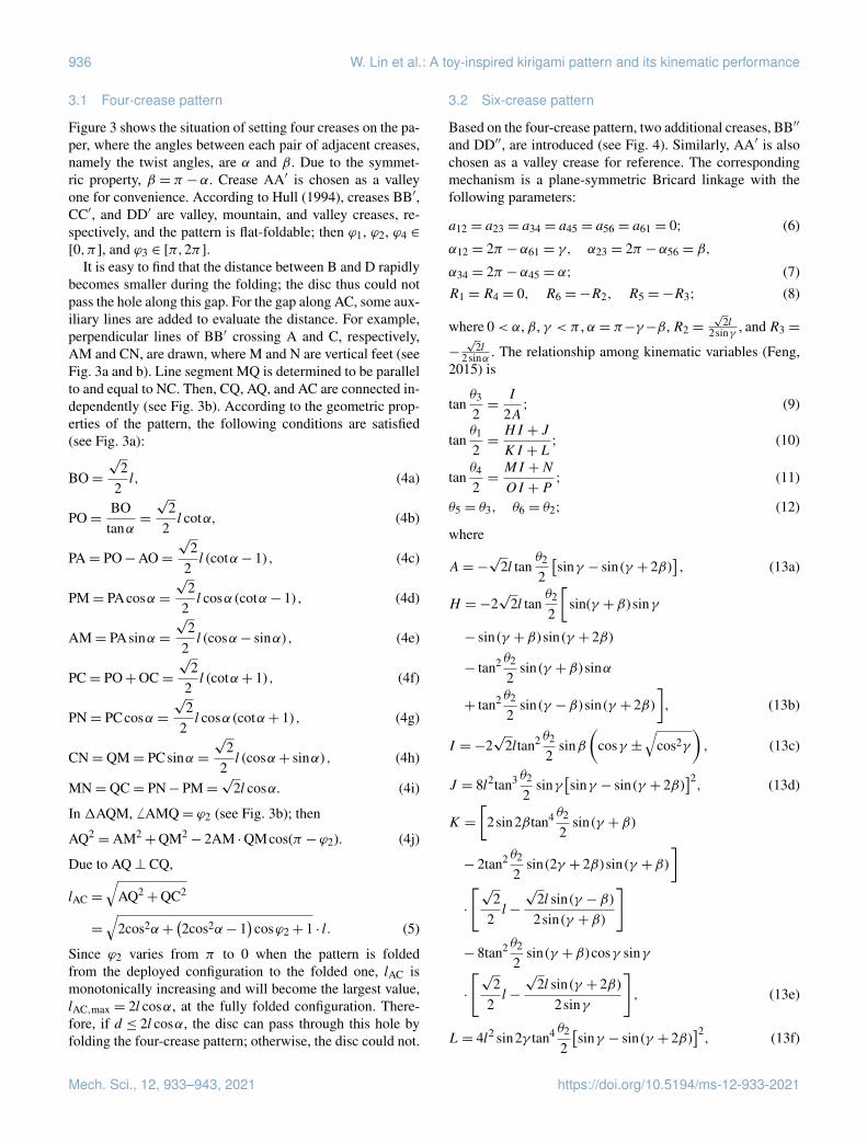
3.1 Four-crease pattern
Figure 3 shows the situation of setting four creases on the pa-per, where the angles between each pair of adjacent creases,namely the twist angles, are α and β. Due to the symmet-ric property, β = π −α. Crease AA′ is chosen as a valleyone for convenience. According to Hull (1994), creases BB′,CC′, and DD′ are valley, mountain, and valley creases, re-spectively, and the pattern is flat-foldable; then ϕ1, ϕ2, ϕ4 ∈
[0,π ], and ϕ3 ∈ [π,2π ].It is easy to find that the distance between B and D rapidly
becomes smaller during the folding; the disc thus could notpass the hole along this gap. For the gap along AC, some aux-iliary lines are added to evaluate the distance. For example,perpendicular lines of BB′ crossing A and C, respectively,AM and CN, are drawn, where M and N are vertical feet (seeFig. 3a and b). Line segment MQ is determined to be parallelto and equal to NC. Then, CQ, AQ, and AC are connected in-dependently (see Fig. 3b). According to the geometric prop-erties of the pattern, the following conditions are satisfied(see Fig. 3a):
BO=
√2
2l, (4a)
PO=BO
tanα=
√2
2l cotα, (4b)
PA= PO−AO=
√2
2l (cotα− 1) , (4c)
PM= PAcosα =
√2
2l cosα (cotα− 1) , (4d)
AM= PAsinα =
√2
2l (cosα− sinα) , (4e)
PC= PO+OC=
√2
2l (cotα+ 1) , (4f)
PN= PCcosα =
√2
2l cosα (cotα+ 1) , (4g)
CN= QM= PCsinα =
√2
2l (cosα+ sinα) , (4h)
MN= QC= PN−PM=√
2l cosα. (4i)
In 1AQM, 6 AMQ= ϕ2 (see Fig. 3b); then
AQ2= AM2
+QM2− 2AM ·QMcos(π −ϕ2). (4j)
Due to AQ⊥ CQ,
lAC =
√AQ2+QC2
=
√2cos2α+
(2cos2α− 1
)cosϕ2+ 1 · l. (5)
Since ϕ2 varies from π to 0 when the pattern is foldedfrom the deployed configuration to the folded one, lAC ismonotonically increasing and will become the largest value,lAC,max = 2l cosα, at the fully folded configuration. There-fore, if d ≤ 2l cosα, the disc can pass through this hole byfolding the four-crease pattern; otherwise, the disc could not.
3.2 Six-crease pattern
Based on the four-crease pattern, two additional creases, BB′′
and DD′′, are introduced (see Fig. 4). Similarly, AA′ is alsochosen as a valley crease for reference. The correspondingmechanism is a plane-symmetric Bricard linkage with thefollowing parameters:
a12 = a23 = a34 = a45 = a56 = a61 = 0; (6)
α12 = 2π −α61 = γ, α23 = 2π −α56 = β,
α34 = 2π −α45 = α; (7)R1 = R4 = 0, R6 =−R2, R5 =−R3; (8)
where 0< α, β, γ < π , α = π−γ−β,R2 =√
2l2sinγ , andR3 =
−
√2l
2sinα . The relationship among kinematic variables (Feng,2015) is
tanθ3
2=
I
2A; (9)
tanθ1
2=HI + J
KI +L; (10)
tanθ4
2=MI +N
OI +P; (11)
θ5 = θ3, θ6 = θ2; (12)
where
A=−√
2l tanθ2
2
[sinγ − sin(γ + 2β)
], (13a)
H =−2√
2l tanθ2
2
[sin(γ +β) sinγ
− sin(γ +β) sin(γ + 2β)
− tan2 θ2
2sin(γ +β) sinα
+ tan2 θ2
2sin(γ −β) sin(γ + 2β)
], (13b)
I =−2√
2ltan2 θ2
2sinβ
(cosγ ±
√cos2γ
), (13c)
J = 8l2tan3 θ2
2sinγ
[sinγ − sin(γ + 2β)
]2, (13d)
K =
[2sin2βtan4 θ2
2sin(γ +β)
− 2tan2 θ2
2sin(2γ + 2β) sin(γ +β)
]·
[√2
2l−
√2l sin(γ −β)
2sin(γ +β)
]
− 8tan2 θ2
2sin(γ +β)cosγ sinγ
·
[√2
2l−
√2l sin(γ + 2β)
2sinγ
], (13e)
L= 4l2 sin2γ tan4 θ2
2
[sinγ − sin(γ + 2β)
]2, (13f)
Mech. Sci., 12, 933–943, 2021 https://doi.org/10.5194/ms-12-933-2021
W. Lin et al.: A toy-inspired kirigami pattern and its kinematic performance 937
Figure 3. The four-crease pattern (a) at the deployed configuration, and (b) at the folding configuration.
M =−2√
2l tanθ2
2
[sin(γ +β) sinγ
− sin(γ +β) sin(γ + 2β)
− tan2 θ2
2sin(γ +β) sinγ
+ tan2 θ2
2sin(γ −β) sin(γ + 2β)
], (13g)
N = 8l2tan3 θ2
2sinγ
[sinγ − sin(γ + 2β)
]2, (13h)
O =
[2sin2βtan4 θ2
2sin(γ +β)
+ 2tan2 θ2
2sin(2γ + 2β) sin(γ +β)
]·
[√2
2l−
√2l sin(γ −β)
2sin(γ +β)
]
+ 8tan2 θ2
2sin(γ +β) sin2γ
·
[√2
2l−
√2l sin(γ + 2β)
2sinγ
], (13i)
P =−4l2 sin2γ tan4 θ2
2
[sinγ − sin(γ + 2β)
]2. (13j)
Here, variable I has two solutions, which represent two mov-ing paths. I remains zero in one of the solutions, whichmeans there is no folding along creases BB′ and DD′, andit degenerates to a spherical 4R mode. The situation, I = 0,is thus not considered in the following analysis, then
I =−4√
2ltan2 θ2
2cosγ sinβ. (14)
Because γ will determine the positions of the added creases(i.e. BB′′ and DD′′) and the range of γ (i.e. γ ∈ (0,π/2),γ = π/2, γ ∈ (π/2,π )) will also influence the distribution ofmountain or valley creases, we will study the three ranges asthree schemes I, II, and III, respectively. It should be noticedthat when γ 6= π/2, Eqs. (9)–(11) become, by considering
Eq. (14),
θ3 = 2arctan
[2tan θ2
2 cosγ sinβsinγ − sin(γ + 2β)
]; (15)
θ1 = 2arctan
(1
tan θ22 cosγ
); (16)
θ4 = θ1, θ5 = θ3, θ6 = θ2. (17)
3.2.1 Scheme I for γ ∈(0,π/2
)When γ ∈ (0,π/2) (see Fig. 4), the relationship betweenupper-dihedral angles and revolute variables is
ϕ2 = π + θ2; (18)
ϕ1 =
θ1 = 2arctan
(1
tan θ22 cosγ
)θ2 ∈ [−π,0) ,
2π + θ1 = 2π + 2arctan(
1tan θ2
2 cosγ
)θ2 ∈ [0,π ] ;
(19)
ϕ3 = π + θ3 = π + 2arctan
[2tan θ2
2 cosγ sinβsinγ − sin(γ + 2β)
]; (20)
ϕ4 = ϕ1, ϕ5 = ϕ3, ϕ6 = ϕ2. (21)
Substituting Eqs. (18)–(20) into Eqs. (15) and (16),
ϕ1 =
−2arctan
(tan ϕ2
2cosγ
)ϕ2 ∈ [0,π ] ,
2π−2arctan(
tan ϕ22
cosγ
)ϕ2 ∈ (π,2π ] ;
(22)
ϕ3=π−2arctan[
2cot ϕ22 cosγ sinβ
sinγ − sin(γ + 2β)
]. (23)
According to Eqs. (21)–(23), when ϕ2 = π and ϕ1 = ϕ4 =
ϕ3 = ϕ5 ≡ π , the pattern locates at the fully deployable con-figuration. While ϕ2 = 0, ϕ1 = ϕ4 ≡ 0, and ϕ3 = ϕ5 ≡ 2π ,the pattern is always flat-foldable. To show the folding per-formance in detail, Fig. 5 shows the curves among upper-dihedral angles for γ = 3π/4, 2π/3, 5π/12 when α = π/6.
https://doi.org/10.5194/ms-12-933-2021 Mech. Sci., 12, 933–943, 2021
938 W. Lin et al.: A toy-inspired kirigami pattern and its kinematic performance
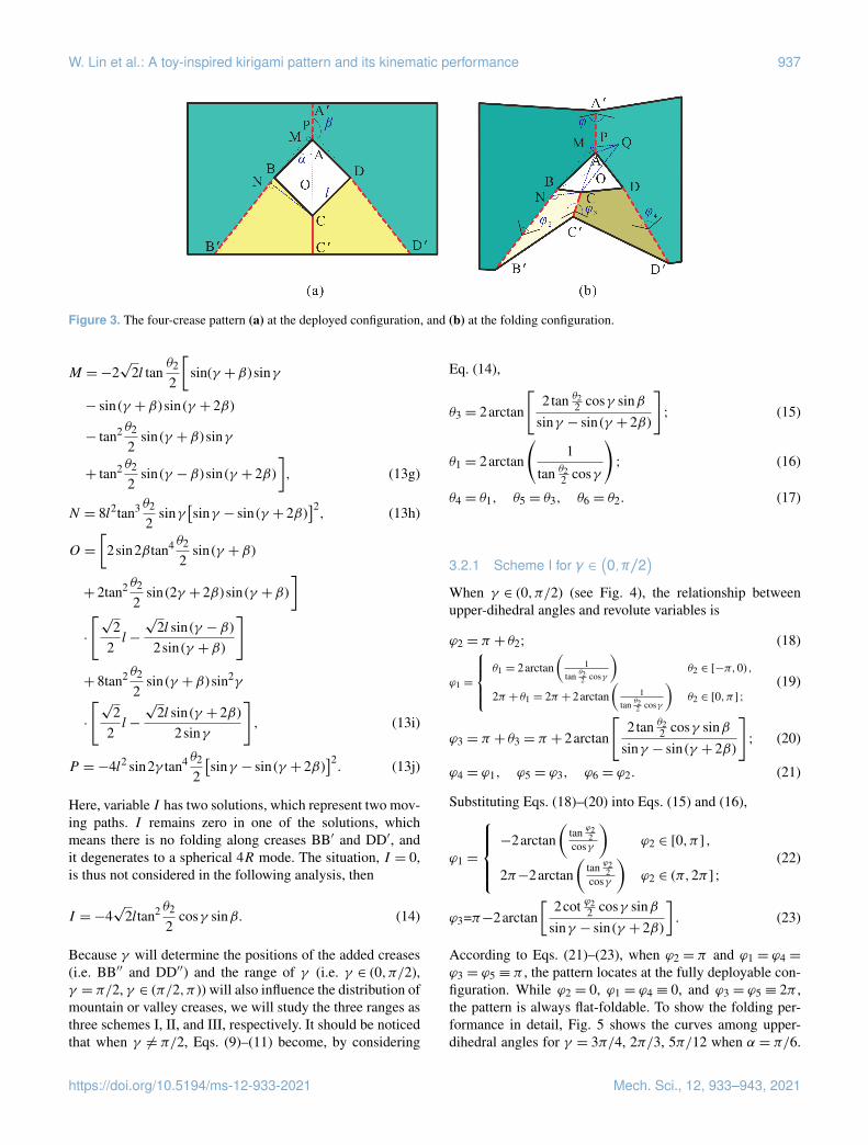
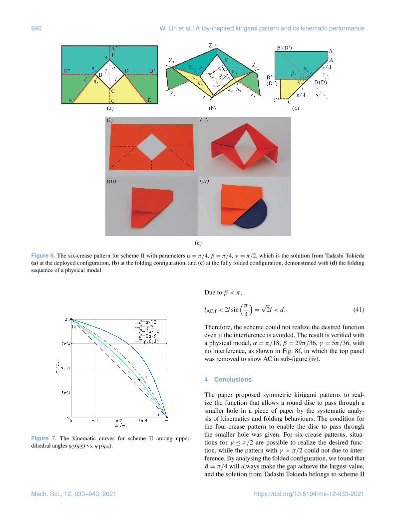
Figure 4. The six-crease pattern for scheme I with parameters α = 5π/36, β = π/4, γ = 11π/18 (a) at the deployed configuration, (b) atthe folding configuration, and (c) at the fully folded configuration, demonstrated with (d) the folding sequence of a physical model.
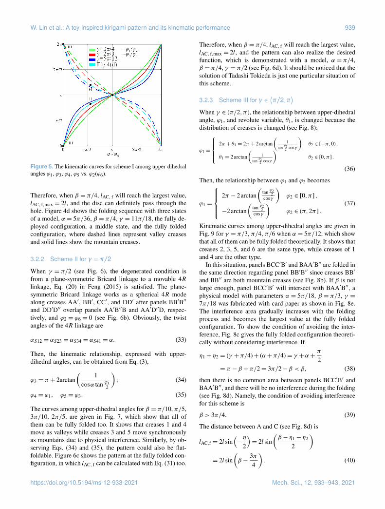
All curves pass through the point (π , π ), which representsthe deployed configuration in a plane, and pass the point (0,0), which represents the fully folded configuration in a plane.The types of creases 1, 2, 4, and 6 are the same and are dif-ferent from those of creases 3 and 5 according to the range ofupper-dihedral angles, and the pattern could be folded alongtwo sides due to ϕ2 = ϕ6 ∈ (0,2π ). The distance between Aand C can be obtained by the transformation of coordinatesystems. In system 1,
1A=[
0 0√
22 l (cotγ + 1) 1
]T, (24)
and in system 4,
4C =[
0 0√
22 l (cotα+ 1) 1
]T. (25)
It can be transformed into system 1,1C = T21T32T43
4C, (26)
in which Tij represents the transformation matrix from sys-tem i to system j (Dai, 2014):
T43 =
cosθ3 −cosα sinθ3 sinα sinθ3 0sinθ3 cosα sinθ3 −sinα cosθ3 00 sinα cosα −
√2l
2sinα0 0 0 1
, (27)
T32 =
cosθ2 −cosβ sinθ2 sinβ sinθ2 0sinθ2 cosβ sinθ2 −sinβ cosθ2 00 sinβ cosβ
√2l
2sinγ0 0 0 1
, (28)
T21 =
cosθ1 −cosγ sinθ1 sinγ sinθ1 0sinθ1 cosγ sinθ1 −sinγ cosθ1 00 sinγ cosγ 00 0 0 1
, (29)
Then, the distance between A and C is
lAC =
∣∣∣1A−1C
∣∣∣ . (30)
To make the disc through the hole, the largest value of lACshould be larger than d, lAC,max > d . According to the above-mentioned analysis, the pattern is flat-foldable. Figure 4cshows the fully folded configuration, in which lAC, f is relatedto η,
η = η1+ η2−β =(γ +
π
4
)+
(α+
π
4
)−β =
3π2− 2β, (31)
Then,
lAC,f = 2l sin(
2π −η
2
)= 2l sin
(π4+β
). (32)
Mech. Sci., 12, 933–943, 2021 https://doi.org/10.5194/ms-12-933-2021
W. Lin et al.: A toy-inspired kirigami pattern and its kinematic performance 939
Figure 5. The kinematic curves for scheme I among upper-dihedralangles ϕ1, ϕ3, ϕ4, ϕ5 vs. ϕ2(ϕ6).
Therefore, when β = π/4, lAC, f will reach the largest value,lAC, f,max = 2l, and the disc can definitely pass through thehole. Figure 4d shows the folding sequence with three statesof a model, α = 5π/36, β = π/4, γ = 11π/18, the fully de-ployed configuration, a middle state, and the fully foldedconfiguration, where dashed lines represent valley creasesand solid lines show the mountain creases.
3.2.2 Scheme II for γ = π/2
When γ = π/2 (see Fig. 6), the degenerated condition isfrom a plane-symmetric Bricard linkage to a movable 4Rlinkage, Eq. (20) in Feng (2015) is satisfied. The plane-symmetric Bricard linkage works as a spherical 4R modealong creases AA′, BB′, CC′, and DD′ after panels BB′B′′
and DD′D′′ overlap panels AA′B′′B and AA′D′′D, respec-tively, and ϕ2 = ϕ6 = 0 (see Fig. 6b). Obviously, the twistangles of the 4R linkage are
αS12 = αS23 = αS34 = αS41 = α. (33)
Then, the kinematic relationship, expressed with upper-dihedral angles, can be obtained from Eq. (3),
ϕ3 = π + 2arctan(
1cosα tan ϕ1
2
); (34)
ϕ4 = ϕ1, ϕ5 = ϕ3. (35)
The curves among upper-dihedral angles for β = π/10, π/5,3π/10, 2π/5, are given in Fig. 7, which show that all ofthem can be fully folded too. It shows that creases 1 and 4move as valleys while creases 3 and 5 move synchronouslyas mountains due to physical interference. Similarly, by ob-serving Eqs. (34) and (35), the pattern could also be flat-foldable. Figure 6c shows the pattern at the fully folded con-figuration, in which lAC, f can be calculated with Eq. (31) too.
Therefore, when β = π/4, lAC, f will reach the largest value,lAC, f,max = 2l, and the pattern can also realize the desiredfunction, which is demonstrated with a model, α = π/4,β = π/4, γ = π/2 (see Fig. 6d). It should be noticed that thesolution of Tadashi Tokieda is just one particular situation ofthis scheme.
3.2.3 Scheme III for γ ∈(π/2,π
)When γ ∈ (π/2,π ), the relationship between upper-dihedralangle, ϕ1, and revolute variable, θ1, is changed because thedistribution of creases is changed (see Fig. 8):
ϕ1 =
2π + θ1 = 2π + 2arctan
(1
tan θ22 cosγ
)θ2 ∈ [−π,0) ,
θ1 = 2arctan(
1tan θ2
2 cosγ
)θ2 ∈ [0,π ] .
(36)
Then, the relationship between ϕ1 and ϕ2 becomes
ϕ1 =
2π − 2arctan
(tan ϕ2
2cosγ
)ϕ2 ∈ [0,π ] ,
−2arctan(
tan ϕ22
cosγ
)ϕ2 ∈ (π,2π ] .
(37)
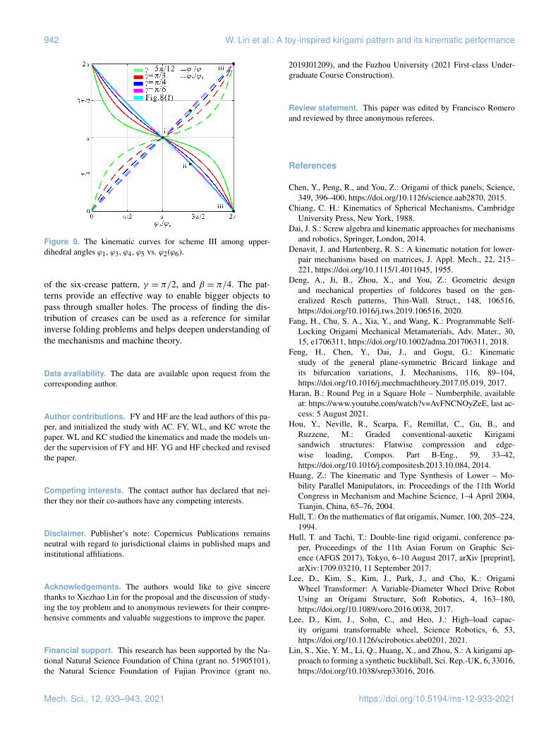
Kinematic curves among upper-dihedral angles are given inFig. 9 for γ = π/3, π/4, π/6 when α = 5π/12, which showthat all of them can be fully folded theoretically. It shows thatcreases 2, 3, 5, and 6 are the same type, while creases of 1and 4 are the other type.
In this situation, panels BCC′B′ and BAA′B′′ are folded inthe same direction regarding panel BB′B′′ since creases BB′
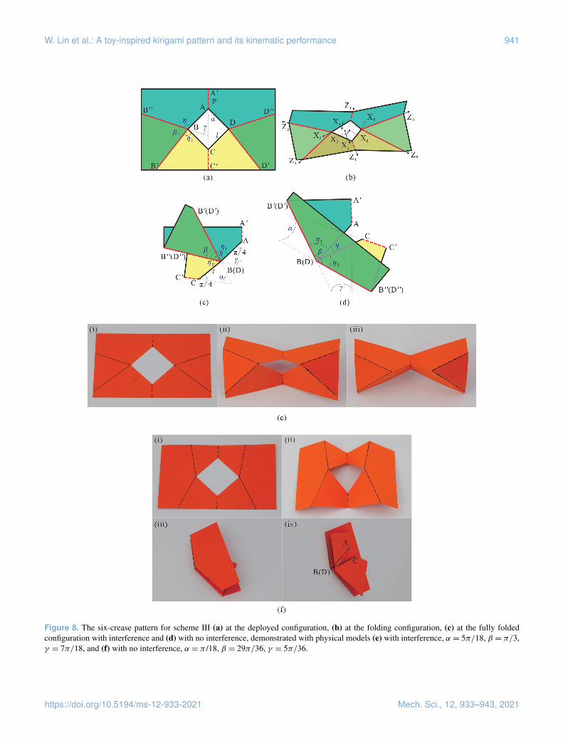
and BB′′ are both mountain creases (see Fig. 8b). If β is notlarge enough, panel BCC′B′ will intersect with BAA′B′′, aphysical model with parameters α = 5π/18, β = π/3, γ =7π/18 was fabricated with card paper as shown in Fig. 8e.The interference area gradually increases with the foldingprocess and becomes the largest value at the fully foldedconfiguration. To show the condition of avoiding the inter-ference, Fig. 8c gives the fully folded configuration theoreti-cally without considering interference. If
η1+ η2 = (γ +π/4)+ (α+π/4)= γ +α+π
2= π −β +π/2= 3π/2−β < β, (38)
then there is no common area between panels BCC′B′ andBAA′B′′, and there will be no interference during the folding(see Fig. 8d). Namely, the condition of avoiding interferencefor this scheme is
β > 3π/4. (39)
The distance between A and C (see Fig. 8d) is
lAC,f = 2l sin(−η
2
)= 2l sin
(β − η1− η2
2
)= 2l sin
(β −
3π4
). (40)
https://doi.org/10.5194/ms-12-933-2021 Mech. Sci., 12, 933–943, 2021
940 W. Lin et al.: A toy-inspired kirigami pattern and its kinematic performance
Figure 6. The six-crease pattern for scheme II with parameters α = π/4, β = π/4, γ = π/2, which is the solution from Tadashi Tokieda(a) at the deployed configuration, (b) at the folding configuration, and (c) at the fully folded configuration, demonstrated with (d) the foldingsequence of a physical model.
Figure 7. The kinematic curves for scheme II among upper-dihedral angles ϕ3(ϕ5) vs. ϕ1(ϕ4).
Due to β < π ,
lAC,f < 2l sin(π
4
)=√
2l < d. (41)
Therefore, the scheme could not realize the desired functioneven if the interference is avoided. The result is verified witha physical model, α = π/18, β = 29π/36, γ = 5π/36, withno interference, as shown in Fig. 8f, in which the top panelwas removed to show AC in sub-figure (iv).
4 Conclusions
The paper proposed symmetric kirigami patterns to real-ize the function that allows a round disc to pass through asmaller hole in a piece of paper by the systematic analy-sis of kinematics and folding behaviours. The condition forthe four-crease pattern to enable the disc to pass throughthe smaller hole was given. For six-crease patterns, situa-tions for γ ≤ π/2 are possible to realize the desired func-tion, while the pattern with γ > π/2 could not due to inter-ference. By analysing the folded configuration, we found thatβ = π/4 will always make the gap achieve the largest value,and the solution from Tadashi Tokieda belongs to scheme II
Mech. Sci., 12, 933–943, 2021 https://doi.org/10.5194/ms-12-933-2021
W. Lin et al.: A toy-inspired kirigami pattern and its kinematic performance 941
Figure 8. The six-crease pattern for scheme III (a) at the deployed configuration, (b) at the folding configuration, (c) at the fully foldedconfiguration with interference and (d) with no interference, demonstrated with physical models (e) with interference, α = 5π/18, β = π/3,γ = 7π/18, and (f) with no interference, α = π /18, β = 29π/36, γ = 5π/36.
https://doi.org/10.5194/ms-12-933-2021 Mech. Sci., 12, 933–943, 2021
942 W. Lin et al.: A toy-inspired kirigami pattern and its kinematic performance
Figure 9. The kinematic curves for scheme III among upper-dihedral angles ϕ1, ϕ3, ϕ4, ϕ5 vs. ϕ2(ϕ6).
of the six-crease pattern, γ = π/2, and β = π/4. The pat-terns provide an effective way to enable bigger objects topass through smaller holes. The process of finding the dis-tribution of creases can be used as a reference for similarinverse folding problems and helps deepen understanding ofthe mechanisms and machine theory.
Data availability. The data are available upon request from thecorresponding author.
Author contributions. FY and HF are the lead authors of this pa-per, and initialized the study with AC. FY, WL, and KC wrote thepaper. WL and KC studied the kinematics and made the models un-der the supervision of FY and HF. YG and HF checked and revisedthe paper.
Competing interests. The contact author has declared that nei-ther they nor their co-authors have any competing interests.
Disclaimer. Publisher’s note: Copernicus Publications remainsneutral with regard to jurisdictional claims in published maps andinstitutional affiliations.
Acknowledgements. The authors would like to give sincerethanks to Xiezhao Lin for the proposal and the discussion of study-ing the toy problem and to anonymous reviewers for their compre-hensive comments and valuable suggestions to improve the paper.
Financial support. This research has been supported by the Na-tional Natural Science Foundation of China (grant no. 51905101),the Natural Science Foundation of Fujian Province (grant no.
2019J01209), and the Fuzhou University (2021 First-class Under-graduate Course Construction).
Review statement. This paper was edited by Francisco Romeroand reviewed by three anonymous referees.
References
Chen, Y., Peng, R., and You, Z.: Origami of thick panels, Science,349, 396–400, https://doi.org/10.1126/science.aab2870, 2015.
Chiang, C. H.: Kinematics of Spherical Mechanisms, CambridgeUniversity Press, New York, 1988.
Dai, J. S.: Screw algebra and kinematic approaches for mechanismsand robotics, Springer, London, 2014.
Denavit, J. and Hartenberg, R. S.: A kinematic notation for lower-pair mechanisms based on matrices, J. Appl. Mech., 22, 215–221, https://doi.org/10.1115/1.4011045, 1955.
Deng, A., Ji, B., Zhou, X., and You, Z.: Geometric designand mechanical properties of foldcores based on the gen-eralized Resch patterns, Thin-Wall. Struct., 148, 106516,https://doi.org/10.1016/j.tws.2019.106516, 2020.
Fang, H., Chu, S. A., Xia, Y., and Wang, K.: Programmable Self-Locking Origami Mechanical Metamaterials, Adv. Mater., 30,15, e1706311, https://doi.org/10.1002/adma.201706311, 2018.
Feng, H., Chen, Y., Dai, J., and Gogu, G.: Kinematicstudy of the general plane-symmetric Bricard linkage andits bifurcation variations, J. Mechanisms, 116, 89–104,https://doi.org/10.1016/j.mechmachtheory.2017.05.019, 2017.
Haran, B.: Round Peg in a Square Hole – Numberphile, availableat: https://www.youtube.com/watch?v=AvFNCNOyZeE, last ac-cess: 5 August 2021.
Hou, Y., Neville, R., Scarpa, F., Remillat, C., Gu, B., andRuzzene, M.: Graded conventional-auxetic Kirigamisandwich structures: Flatwise compression and edge-wise loading, Compos. Part B-Eng., 59, 33–42,https://doi.org/10.1016/j.compositesb.2013.10.084, 2014.
Huang, Z.: The kinematic and Type Synthesis of Lower – Mo-bility Parallel Manipulators, in: Proceedings of the 11th WorldCongress in Mechanism and Machine Science, 1–4 April 2004,Tianjin, China, 65–76, 2004.
Hull, T.: On the mathematics of flat origamis, Numer, 100, 205–224,1994.
Hull, T. and Tachi, T.: Double-line rigid origami, conference pa-per, Proceedings of the 11th Asian Forum on Graphic Sci-ence (AFGS 2017), Tokyo, 6–10 August 2017, arXiv [preprint],arXiv:1709.03210, 11 September 2017.
Lee, D., Kim, S., Kim, J., Park, J., and Cho, K.: OrigamiWheel Transformer: A Variable-Diameter Wheel Drive RobotUsing an Origami Structure, Soft Robotics, 4, 163–180,https://doi.org/10.1089/soro.2016.0038, 2017.
Lee, D., Kim, J., Sohn, C., and Heo, J.: High–load capac-ity origami transformable wheel, Science Robotics, 6, 53,https://doi.org/10.1126/scirobotics.abe0201, 2021.
Lin, S., Xie, Y. M., Li, Q., Huang, X., and Zhou, S.: A kirigami ap-proach to forming a synthetic buckliball, Sci. Rep.-UK, 6, 33016,https://doi.org/10.1038/srep33016, 2016.
Mech. Sci., 12, 933–943, 2021 https://doi.org/10.5194/ms-12-933-2021

W. Lin et al.: A toy-inspired kirigami pattern and its kinematic performance 943
Liu, S. Y. and Chen, Y.: Myard linkage and its mo-bile assemblies, Mech. Mach. Theory, 44, 1950–1963,https://doi.org/10.1016/j.mechmachtheory.2009.05.001, 2009.
Marras, A. E., Su, H. J., and Castro, C.: Design of DNA OrigamiMachines and Mechanisms, in: ASME 2019 ASME Interna-tional Design Engineering Technical Conferences, 18–21 Au-gust 2019, Anaheim, CA, https://doi.org/10.1115/IMECE2012-87848, 2019.
Masayuki, E. and Hiroshi, S.: DNA OrigamiNanomachines, Molecules, 23, 1766,https://doi.org/10.3390/molecules23071766, 2018.
Pesenti, M., Masera, G., and Fiorito, F.: Shaping an origami shadingdevice through visual and thermal simulations, Enrgy. Proced.,78, 346–351, https://doi.org/10.1016/j.egypro.2015.11.663,2015.
Rafsanjani, A., Zhang, Y., Liu, B., Rubinstein, S. M.,and Bertoldi, K.: Kirigami skins make a simplesoft actuator crawl, Science Robotics, 3, eaar7555,https://doi.org/10.1126/scirobotics.aar7555, 2018.
Wang, X., Guest, S. D., and Kamien, R. D.: Keeping It Together:Interleaved Kirigami Extension Assembly, Phys. Rev. X, 10,011013, https://doi.org/10.1103/physrevx.10.011013, 2020.
Yang, Y., Vella, K., and Holmos, D. P: Grasp-ing with kirigami shells, Science Robotics, 6, 54,https://doi.org/10.1126/SCIROBOTICS.ABD6426, 2021.
Yu, Y., Chen, Y., and Paulino, G. H.: On the unfolding process oftriangular Resch patterns: a finite particle method investigation,in: Proceedings of the ASME 2019 International Design Engi-neering Technical Conferences, 18–21 August 2019, Anaheim,CA, USA, V05BT07A048, https://doi.org/10.1115/DETC2019-98121, 2019.
Zhang, X. and Chen, Y.: Mobile assemblies of Bennett linkagesfrom four-crease origami patterns, P. Roy. Soc. A, 474, 2210,https://doi.org/10.1098/rspa.2017.0621, 2018.
Zhang, X. and Chen, Y.: Vertex-splitting on a dia-mond origami pattern, J. Mech. Robot., 11, 031014,https://doi.org/10.1115/1.4043214, 2019.
Zhang, Y., Yan, Z., Nan, K., and Xiao, D.: A mechanicallydriven form of kirigami as a route to 3D mesostructures inmicro/nanomembranes, P. Natl. Acad. Sci. USA, 112, 11757–11764, https://doi.org/10.1073/pnas.1515602112, 2015.
https://doi.org/10.5194/ms-12-933-2021 Mech. Sci., 12, 933–943, 2021