Embed Size (px)
Citation preview
Int. J. Communications, Network and System Sciences, 2011, 4, 683-695 doi:10.4236/ijcns.2011.411084 Published Online November 2011 (http://www.SciRP.org/journal/ijcns)
Copyright © 2011 SciRes. IJCNS
A Topology-Based Conflict Detection System for Firewall Policies Using Bit-Vector-Based Spatial Calculus
Subana Thanasegaran, Yi Yin, Yuichiro Tateiwa, Yoshiaki Katayama, Naohisa Takahashi Department of Computer Science and Engineering, Nagoya Institute of Technology, Nagoya, Japan
E-mail: {subana, katayama, tateiwa, naohisa}@moss.elcom.nitech.ac.jp, [email protected] Received September 1, 2011; revised September 30, 2011; accepted October 12, 2011
Abstract Firewalls use packet filtering to either accept or deny packets on the basis of a set of predefined rules called filters. The firewall forms the initial layer of defense and protects the network from unauthorized access. However, maintaining firewall policies is always an error prone task, because the policies are highly com- plex. Conflict is a misconfiguration that occurs when a packet matches two or more filters. The occurrence of conflicts in a firewall policy makes the filters either redundant or shadowed, and as a result, the network does not reflect the actual configuration of the firewall policy. Hence, it is necessary to detect conflicts to keep the filters meaningful. Even though geometry-based conflict detection provides an exhaustive method for error classification, when the number of filters and headers increases, the demands on memory and computation time increase. To solve these two issues, we make two main contributions. First, we propose a topol- ogy-based conflict detection system that computes the topological relationship of the filters to detect the con- flicts. Second, we propose a systematic implementation method called BISCAL (a bit-vector-based spatial calculus) to implement the proposed system and remove irrelevant data from the conflict detection computa- tion. We perform a mathematical analysis as well as experimental evaluations and find that the amount of data needed for topology is only one-fourth of that needed for geometry. Keywords: Packet Filtering, Misconfiguration, Network Security, Spatial Analysis
1. Introduction
A firewall protects the network from unauthorized access and provides secure access to the outside world. Packet filtering techniques in a firewall provide an initial level of security and operate on the network layer or the inter- net layer. Packet filtering controls the network traffic with a predefined, ordered set of filters called a firewall policy (FP). Every filter f in the FP has a condition and an action. If a filter matches a packet P the filter action is carried out on packet P. The action can be either accept or deny the packet. Many packet filtering schemes such as IPFW or IPFIREWALL in FreeBSD is a first match-ing filtering scheme [1]. IPFW is a FreeBSD sponsored firewall software application enables use of sophisticated filtering capabilities.
Managing and maintaining firewall policies is an ex- tremely complicated job for the network administrator because the policies are constantly subject to modifica- tion. For example, while examining 37 firewalls in pro- duction enterprise networks, Wool found that all the
firewalls were misconfigured and vulnerable [2]. When the network behavior is different from the ac-
tual configuration of a policy, potential security holes are created. For example, if an IP address is mistaken in an FP, it allows unintended traffic in the network and can cause security holes. A conflict is a type of misconfigu- ration that occurs when a packet P matches two or more filters. It is a common misconfiguration in firewalls. Hamed et al. found that there is a high probability of even expert system administrators and network practi- tioners creating conflicts [3]. Conflicts render the filters redundant or shadowed, and as a result, the actual con- figuration of the firewall policy is not reflected in the network.
Various techniques have been developed to manage firewall policies [3-22]. Among these are firewall analy- sis tools [4,5] and techniques that focus on minimizing the firewall rules [6]. Other related works detect conflicts by using geometrical analysis [7-9]. Yin et al. developed a conflict detection technique based on geometrical analysis, which provides systematic conflict classifica-

S. THANASEGARAN ET AL. 684
tion [8]. However, this technique becomes very de- manding in terms of memory and computation time when the number of header fields and filters increases. To solve this problem, we have presented a topological approach to detect conflicts [10,11]. In this approach, we introduced a bit-vector based spatial calculus named BISCAL and constructed a new conflict detection frame- work through BISCAL which analyzes the topological relationship of the filters to detect and classify conflicts. This paper extends and strengthens that framework by describing the design and implementation of the topol- ogy-based conflict detection system that shows how ef- fectively the BISCAL can be adopted for conflict de- tection and by presenting quantitative evaluations of the system. In this paper, our main contributions are as fol- lows:
1) We have presented a systematic implementation method based on BISCAL to construct a conflict detec- tion system that efficiently classifies conflicts by treating with topological relationships between filters effectively, and can remove the irrelevant data from the conflict de- tection in the intermediate stage of computation.
2) We have performed comparative studies through mathematical and experimental analysis to show that the topological approach requires much less computation time and storage than geometrical approach in conflict detection.
We implement the topological approach using BIS- CAL to extract the conflicting filters from the firewall policy. The main advantage of BISCAL is that the opera- tions on the filter sets become easier. The rest of the pa- per is organized as follows. In Section 2, we discuss re- lated works. In Section 3, we explain the firewall policy used in the conflict detection system. Section 4 discusses the spatial relationship of the filters, and Section 5 ex-plains the conflict classification in detail. The operators and supporting vectors of BISCAL are explained in Sec-tion 6. Section 7 gives an overview of the proposed sys-tem and its computational steps. The evaluation and comparative analysis of our approach are discussed in Section 8. And finally, in Section 9, we present the con-clusions and discuss future research directions.
2. Related Work
Over the past few years, research and analysis of firewall policies has received considerable attention [2-28]. Al- Share et al. proposed an algorithm to detect conflicts caused by one filter on another in a firewall policy on the basis of the relationship between the two filters [12]. This relationship was defined according to their predi- cates such that they satisfied the conditions in {⊂ ⊃ =}. However, the problem with this algorithm is that when the corresponding predicates of two filters overlap,
the relationship between the two filters cannot be deter- mined, because overlapping predicates do not satisfy any of the conditions in{⊂ ⊃ =}. Therefore, the algorithm for detecting conflicts also does not work when overlap- ping predicates appear between two filters.
V. Capretta et al. proposed a formalization of conflict detection for firewalls. They defined conflict for the rules if and only if the actions of the rules are different [13]. In such conflict detection, redundancy cannot be detected, as the redundant filters have the same action, but our system analyzes the filters with both the same and dif- ferent actions, and conflicts are classified in detail.
Mayer et al. developed a firewall analysis tool Fang to perform customized queries on a set of filters and to ex- tract the filters in a firewall policy [4]. Wool et al. im- proved the usability of Fang [5]. These tools and meth- ods help administrators to manually verify the correct- ness of a firewall policy. Unfortunately, they require a high degree of user expertise to write proper queries and identify the problems in firewall policies.
H. G. Verizon et al. proposed a fast and scalable method for resolving the anomalies in firewall policies [14], which can be useful for large-scale firewall policies. H. Hu et al. proposed a firewall anomaly management and resolution environment: FAME, and developed a grid-based visualization of the firewall policy [15]. Liu et al. used firewall decision trees to detect and remove the redundant filters [16]. K. Matsuda proposed a model called matrix decomposition to analyze the filters in the firewall policy with a few compression methods [17]. If for some reason, an administrator needs to intentionally embed redundant filters, which will conflict with the other filters in a firewall policy, we will inform the ad- ministrator of the presence of conflicts instead of re- moving these redundant filters. This also helps the ad- ministrators to add, delete, or modify the existing filters according to their own intentions, as we have classified the conflict contents in detail.
T. Srinivasan et al. proposed a scalable and parallel packet classification method using an aggregated bit vector [24]. Lakshman et al. proposed high-speed pol- icy-based packet forwarding using bit-level parallelism [25]. Both the above methods yield good results by using the bit-vector data structure for packet classification schemes. Baboescu et al. proposed a fast and scalable conflict detection technique for packet classifiers using a bit-vector. It detects the conflicting pairs, but it does not classify the conflicts explicitly [22]. Our method effi- ciently utilizes the bit-vector in our conflict detection system through BISCAL and explicitly classifies as er- rors and warnings, which helps administrators to re-con- figure the policies more easily.
Copyright © 2011 SciRes. IJCNS
S. THANASEGARAN ET AL. 685 3. Background
An FP consists of an ordered set of m filters, and it is expressed as follows:
0 1 1FP : , , , mf f f
where if two filters, if and , 0, 1 and , jf i j m i j are such that i < j, filter if is placed before jf in the FP. We follow the first matching filter scheme, and therefore, if has a higher priority than jf during exe-
cution. Each filter 0, 1 if i n consists of n key
fields, called predicates 0 1 1 and an action. The filter
,i i inp p p if is expressed as shown below:
0 1 1: , , actioni i i inf p p p
The commonly used matching keys in a header are protocol (represented as Pro), source IP (SrcIP), destina- tion IP (DesIP), source port (SrcPort), and destination port (DesPort).
Each predicate 0, 1 , 0, 1 ikp i m k n
can be represented as an exact value, a prefix, a range value, or a list in many firewall systems. However, in this paper, we use range value for the sake of simplicity and because a filter with predicates in other forms can be easily con- verted into one or multiple filters with range values. Each predicate 0, 1 , 0, 1 ikp i m k n
a u b is rep-
resented as ik k ik , by using a uniform range value and the value in the kth key field of the packet header, uk. The default filter is the lowest priority filter that denies access to all the packets when no other filter matches the packet.
,ika b ik
We represent a filter in the form called internal form, which includes the range values instead of the predicates in n key fields. An internal form filter fi is represented as follows:
0 0 1 1 1 1: , , , , , action i i i i i in inf a b a b a b
Assume that the values of the header of packet P are represented as . A packet P matches fi if and 0 1 1, nu u u
,a u b a only if .
An example policy consisting of internal form filters is shown in Table 1, where f5 is the default filter.
0 0 0 0 0 0 1 1i i i i in nu b a u b 1in
4. Spatial Relationship of Filters
According to Max J. Egenhofer, we can classify the spa- tial relationships on the basis of the spatial concepts [29]. The three relationships are 1) topological relationships, 2) spatial and strict order relationships, and 3) metric (geo- metric) relationships. Here, we focus on geometric and topological relationships and analyze how they differ in terms of conflict detection.
Table 1. A sample firewall policy FP1.
SrcIP DesIP Action
f0 [0,3) [3,7) Accept
f1 [0,3) [3,7) Deny
f2 [1,5) [1,5) Accept
f3 [3,5) [1,3) Deny
f4 [5,7) [1,3) Accept
f5 [0,232) [0,232) Deny
4.1. Geometric Relationship of Filters
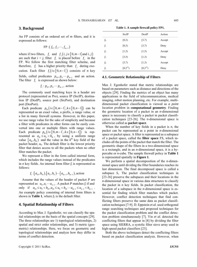
Max J. Egenhofer stated that metric relationships are based on parameters such as distance and directions of the objects [29]. Finding the metrics of an object has many applications in the field of telecommunication, medical imaging, robot motion planning, etc. For example, multi- dimensional packet classification is viewed as a point location problem in computational geometry. Finding the geometric location of a packet in an n-dimensional space is necessary to classify a packet in packet classifi-cation techniques [23-26]. The n-dimensional space is otherwise called as packet space.
When the number of key fields in a packet is n, the packet can be represented as a point in n-dimensional space or packet space. A filter is represented as a subspace of a packet space, called the filter space FS, which in- cludes all the points of the packet that match the filter. The geometric shape of the filters in a two-dimensional space is a rectangle, and in an n-dimensional space, it is a hy- percube or n-cube. The sample firewall policy in Table 1 is represented spatially in Figure 1.
We perform a spatial decomposition of the n-dimen- sional space until dividing the filter boundaries reaches its last dimension. The final decomposed space is called a subspace Si. The packet classification techniques in [23-26] preserve the subspaces and their locations in the n-dimensional space in various data structures to classify the packet in n key fields. In packet classification, the location of a subspace in the n-dimensional space is es-sential for finding which filter matches which packet. However, conflict detection techniques that find con- flicting filters preserve the same data as packet classifi- cation techniques [7-9]. D. Eppstein et al. used orthogonal range searching techniques and proposed techniques for the packet classification problem and the conflict detec- tion problem simultaneously [7]. Yin et al. detected the conflicting filters that appear in [8] by dividing the filter space using SIERRA, a systolic filter sieve array used in high-speed packet classifiers [23].
Both the above techniques detect the conflicting filters based on packet classification analysis. However, when
Copyright © 2011 SciRes. IJCNS

S. THANASEGARAN ET AL. 686
the number of key fields and filters increases, the con- ventional methods used in [7-9] are extremely demand- ing in terms of memory and computation time, as they depend on geometry-based packet classification tech- niques. As far as conflicts are concerned, rather than us- ing packet classification, we should focus on filter classi- fication. Therefore, in our paper, we propose to focus only on filter classification and therefore solve the drawbacks of the previous approaches based on the geometrical relationship of the filters.
4.2. Topological Relationship of Filters
According to Max J. Egenhofer, topological relationships are a subset of spatial relationships [29]. Topological notations include the concepts of continuity, closure, interior, and boundary, and are defined in terms of neigh- borhood relations. Topological equivalence is a crucial criterion when comparing the relationships between ob- jects. Topological equivalence does not preserve distances and directions. Topology refers to the way in which the filters are connected to each other. Therefore, filter clas- sification can be performed by identifying the topologi- cal relationship of the filters, which is the basic require- ment for conflict detection.
In our approach, as we have discussed earlier, we per- form the n-dimensional spatial decomposition, and then further analyze the filters in the subspaces to find the topological relationships of the filters. The difference between the number of subspaces required for conflict detection using topology and geometry is explained be- low. Geometry-based systems consider all the subspaces for conflict detection, as the location of all the subspace is important for packet classification techniques. In a topology-based system, the location is discarded, and concentrates only on the uniqueness of the subspace. In other words, it only selects the subspaces with different filter sets by removing subspaces with the same filter sets.
Therefore, the number of subspaces (the amount of data required for conflict detection) is smaller for topol- ogy-based systems than for geometry-based systems.
For example, in Figure 1, the number of subspaces considered in the geometrical approach is thirteen. In the topological approach, it is five, because there are only five unique subspaces with different filter sets, namely 0 1 0 1 2 2 2 3 4, , , , , , , ,f f f f f f f f f . As a result,
when the number of filters and key fields increase, the difference in the number of subspaces considered for conflict detection varies drastically between the topo- logical and geometrical approaches. Therefore, we can say that identifying only the topological relationships improves the efficiency of the conflict detection system
by removing the irrelevant data from the conflict com- putation. In this way, we can achieve our target of solv- ing the two issues, namely, large memory usage and computation time. We use experiments to verify this in later sections.
Conflict detection is performed by finding the topo- logical relationship of the filters. There are nine possible topological relations between any two objects, as they appeared in [29]. We have extracted five topological relationships (TR) to identify conflicts between any pair of filters, if and jf . In other words, TR (fi, fj) = {dis- joint, inside, contains, equal, overlap}. The relations are shown in two dimensions in Figure 2, and can be gener- alized for higher dimensions. The filter space of a filter f is represented by FS (f).
Disjoint: TR ,i jf f = disjoint when the intersection of the filters spaces is empty or FS FS i jf f , as shown in Figure 2(a).
Inside: TR ,i jf f = inside when fj is completely
enclosed by fi or FSFS j if f , as shown in Figure
2(b). Contains: When if is enclosed by filter jf , or FS FSj if f , then we say that there exists a rela-
tion TR ,i jf f = contains between filters fi and fj, as
shown in Figure 2(c). Contains is the converse of the inside relation.
Equal: TR ,i jf f = equal when if and jf are equal, or FS FSi if f , as shown in Figure 2(d).
f0, f1
f2
f3 f4
SrcIP
DesIP232
232
0 1 3 75
1
3
5
f57
S0
S1
S4
S5
S8 S11
S3 S7 S10
S2 S6 S9 S12
Figure 1. Spatial decomposition of filters of FP1 defined in Table 1.
fi fj fi
fj
fifjfifj
fi
fj
(a) (b) (c) (d) (e)
Figure 2. Topological Relationships. (a) Disjoint; (b) Inside; (c) Contains; (d) Equal; (e) Overlap.
Copyright © 2011 SciRes. IJCNS
S. THANASEGARAN ET AL. 687
Overlap: When if and jf do not satisfy any one of the above four relationships, then we can say that
TR ,i j f f = overlap, as shown in Figure 2(e).
5. Classification of Conflicts
Conflicts are classified in filter pairs, ,i jf f , where i < j and filter fj has an error or warning caused by fi. The errors and warnings of the filter fj can be classified ex- clusively by the type of topology between fj and fi and the actions of fj and fi as follows.
1) Shadowing error: A filter fj has a shadowing error caused by fi when
a) TR (fi, fj) = equal, fi·action ≠ fj·action, b) TR (fi, fj) = inside, fi·action ≠ fj·action. In this case, the filter fj is never executed, as fi prevents
fj from matching all the packets. 2) Redundancy error: A filter fj has a redundancy
error caused by fi when a) TR (fi, fj) = equal, fi·action = fj·action, b) TR (fi, fj) = inside, fi·action = fj·action. In this case, the filter fj is never executed, as the filter fi
prevents fj from matching all the packets that fj can match. The redundant filters in the FP unnecessarily increase the size of the FP, and even removing fj does not change the semantics of FP.
3) Correlation warning: A filter fj has a correlation warning caused by fi when
TR (fi, fj) = overlap, fi·action ≠ fj·action.
If filter fj has a correlation warning caused by fi, fj is sometimes not executed for the packets that match the filter fi.
4) Generalization warning: A filter fj has a generali- zation warning caused by fi when
TR (fi, fj) = contains, fi·action ≠ fi·action.
The filter fj is executed only when packets arrive that does not satisfy fi.
5) Redundancy warning: A filter fj has a redundancy warning caused by fi when
a) TR (fi, fj) = contains, fi·action = fj·action, b) TR (fi, fj) = overlap, fi·action = fj·action The filter fj is sometimes executed, as fi prevents fj
from matching some packets that can match fj. However, if a filter fj is disjoint to the other filters, then it does not fall within any of the above conflict classifications. In this case, we refer to it as a neither error nor warning filter.
6. BISCAL
BISCAL operates on the filter sets to extract the topo- logical relationship of the filters. It treats the filter sets in a bit-vector format and uses seven primitive operators to
find the topological relationship of the filters and three special vectors called characterization vectors to preserve the intermediate results. The main advantage of BISCAL is that it finds the disjoint filters in the intermediate stage of computation and removes those filters from the con- flict computation. This is because a filter that is disjoint in any dimension is always disjoint in n dimensions.
6.1. Data Structure: Bit-Vector
An FP which consists of m filters is represented by a bit-vector 0b b 1m , where a bit bi in the bit-vector represents the filter fi. If a filter is selected from the FP, then the value of the corresponding bit is 1, and if not, then the value of the bit is 0. For example, let FP0 con- sist of 0 1 2 3, , , , 4f f f f f . If filters 1 3 4, ,f f f are se- lected from FP0, then the bit-vector is [01011]. Because this paper focuses on bit-vectors, hereinafter we will re- fer to a bit-vector as simply vector. The main reason for choosing the bit-vector representation is that it makes easier to apply logical operations to find the topological relationships between the filters. We introduce a function V2S that transforms the 1 s in the vector to its corre- sponding filters. For example, V2S ([11100]) = {f0, f1, f2}.
6.2. Primitive Operators
There are seven primitive operators in BISCAL that compute the topological relationships of the filters. They are explained with example vectors v1 and v2, where v1= [1010] and v2 = [1011].
1) AND Operator (AND): This operator computes a bit-wise AND for a set of vectors. For example, AND ({v1, v2}) = AND ({[1010], [1011]}) = [1010].
2) Cartesian-AND Operator (C-AND): It computes the Cartesian product of two sets of vectors A and B and then computes the logical AND for the resulting vectors. C-AND (A, B) = {AND ((a, b)), | (a, b) ∈ A × B}.
3) OR Operator (OR): This operator computes a bit-wise OR for a set of vectors. For example, OR (v1, v2) = OR ({[1010], [1011]}) = [1011].
4) Counting one Operator (C1): This operator counts the number of 1s in an input vector. For example, C1 (v1) = C1 ([1010]) = 2.
5) NOT Operator (NOT): This operator returns the complement of an input vector. For example, NOT (v1) = NOT ([1010]) = [0101].
6) Pair-filters Operator (PF): This operator returns a set from two filter sets that contain the possible combi- nations of the two filters in each of the input vectors. For example, PF ([1010], [1011]) = {{f0, f2}, {f0, f2}, {f0, f3}, {f2 f3}}.
Copyright © 2011 SciRes. IJCNS

S. THANASEGARAN ET AL. 688
5
7) Permutation Operator (PO): This operator returns a set from two filter sets in which each filter is a filter selected from each of two input filter sets. For example, PO ({f0}, {f1, f2}) = {{f0, f1}, {f0, f2}}.
6.3. Characterization Vectors
Characterization vectors are the vectors that characterize the topological relationship of the filters. There are two types of characterization vectors: 1) vectors characterize- ing the topological relationship of the filters in the packet space, called CV and, 2) vectors characterizing the topo- logical relationship of the filters projected on each axis of the packet space, called PCV.
6.3.1. Characterization Vectors for Filters in the Packet Space
CVs characterize the topological relationship of the fil- ters in n-dimensional packet space. They consist of the following three kinds of vectors.
1) Co-Existence Vectors Set (OVS): OV is a vector in which a bit of the vector is 1 if the corresponding filter co-exists with another filter in some subspace of the packet space. OVS is a set of all OVs. For example, in Figure 1, f0, f1 and f2 co-exist in S4, therefore the vector representation is, OV = [11100].
2) Fully Covered Vector (FV): FV is vector in which the value of bi is 1, if fi is fully covered in n-dimensional space. For example, in Figure 1, f0, f1 and f3 are fully covered in two-dimension and therefore, FV = [11010].
3) Disjoint Vector (DV): If a filter fi is disjoint from all other filters in n-dimensional space, then the value of bit bi is set to 1 in DV. For example, in Figure 1, f4 is a disjoint filter and therefore DV = [00001].
6.3.2. Characterization Vectors for Projections of Filters on Each Axis of the Packet Space
PCVs are computed by using the projection of the filters on each axis of the packet space. The 1m is an ordered set of the ith predicates of the filters in FP and the projection of the filters on the ith axis of the packet space corresponding to the ith key, Xi. All the pro- jected filters except for the default filter are decomposed in the boundaries specified by their ith predicate. As a result of the decomposition, the axis is divided into mul- tiple intervals. Figure 3 shows an example of the spatial division for the projection of the filters in FP1 on the 0th axis corresponding to the 0th key X0 or SrcIP and shows that six intervals,
0 , ,iX f f
0 , ,I I , ,
, are made by the decomposi- tion of 0 0 5X f f .
Each interval has a set of filters, called sub-domain filter set, in which ith predicate of the filter is always true within the interval. The sub-domain filter sets for all the
f0
f1
f3
f2f4
{f0,f1} {f0,f1,f2} {f2} {f2,f3} {f4}
SrcIP (X0)
0 1 2 3 4 5
I0 I1 I2 I3 I4 I5
{ }
Figure 3. Spatial division for the projection of the filters in FP1 on the 0th key X0 or SrcIP. intervals on the ith axis except the empty sets form a set, named SFSi. Each sub-domain filter set is transformed into a vector, and as a result, the SFSi is transformed into a set of vectors, SVSi. If a filter fi exists in a sub-domain filter set, the corresponding bit of the vector bi is set to 1. For example, SFS0 = 0 1 0 1 2 2 2 3, , , , , , , ,f f f f f f f f
4f and SVS0 = 11000 , 11100 , 00100 , 00110 ,
00001 for the spatial division for the projection of the filters in FP1 mentioned in the above.
PCVi characterizes the topological relationship of the projected filters on the ith axis and consists of the fol- lowing three kinds of vectors.
1) POVSi: POVi is a vector in which a bit of the vec- tor is 1 if the corresponding projected filter co-exists with another projected filter in some interval on the ith axis of the packet space. POVSi is a set of all POVSis. For example, in Figure 3, POVS0 = {[11000], [11100], [00110]}.
2) PFVi: PFVi is vector in which the value of bit bi is 1 if the projection of fi is fully covered on ith axis of the packet space. For example, in Figure 3, the projections of {f0, f1} and {f3} are fully covered and therefore, PFV0
= [11010]. 3) PDVi: If a filter fi is disjoint from all other filters
projected on ith axis of the packet space, then the value of bi is set to 1 in PDVi. For example, in Figure 3, f4 is dis- joint and therefore PDV0 = [00001].
7. Implementation of Topology-Based Conflict Detection System
7.1. System Overview
The proposed system detects and classifies the conflicts in the given firewall policy, FP, which consists of m fil- ters and n key fields. The default filter is the least prior- ity filter fm–1 and is not considered for conflict detection
Copyright © 2011 SciRes. IJCNS

S. THANASEGARAN ET AL.
Copyright © 2011 SciRes. IJCNS
689
1m
7.2. PCV Extractor as it always conflicts with the remaining filters. Our sys- tem computes the topological relation of each filter pair (fi, fj), where fj is the conflicting filter and fi is the conflict causing filter. It then decides the errors and warnings for fj according to the topological relation based on the con- flict classification described in Section 4.
The PCV extractors calculate POVSs, PDVs and PFVs by the following steps.
STEP 3-1: POVSi is computed as follows: Initialize POVSi = {Ø}; For all v ∈ SVSi, if C1 (v) > 1, POVSi = POVSi ∪ v; The overview of the proposed system is shown in
Figure 4 and consists of a vertical decomposer, spatial divisors, PCV extractors, a CV extractor, and a TR ex- tractor.
For example, POVS0 = 11000 , 11100 , 00110 for the SVS0 calculated above.
STEP 3-2: PDVi is calculated as follows: PDVi = NOT (OR (POVSi)); The system receives the FP, and follows the procedure
given below. For example, when POVS0 is the value calculated above, PDV0 = NOT 11110 00001 . STEP 1: The vertical decomposer divides the FP into
n sequences. Each sequence includes the ith predicate of the filters in FP and represents projections of the filters in FP on the ith axis of the packet space, , where i is from 0 to n – 1.
0 , ,iX f f
STEP 3-3: In the calculation of PFVi, the non-fully covered filters on the ith axis of the packet space are computed initially and lastly the fully covered filters are computed. The non-fully covered filters are identified in NFi by finding a vector in SVSi with a single 1, because the non-fully covered filters are somehow alone in any subspace. For example, in Figure 3, f2 is a non-fully covered filter, because f2 is alone in I2. In this way, the corresponding bits of non-fully covered filters are made 0, and the fully covered vector PFVi is derived.
STEP 2: The spatial divisor makes SFSi by the spatial division of the projection 1m on the ith axis in the way as described in the Section 6.3.2 for each projection where i is from 0 to n – 1.
0 , ,iX f f
STEP 3: The PCVi extractor transforms SFSi into SVSi in the way as described in the Section 6.3.2 and calculates PCVi by applying the BISCAL to the vectors in the SVSi where i is from 0 to n – 1.
Initialize NFi = {Ø}; For all v ∈ SVSi, if C1 (v) =1, NFi = NFi ∪ v; PFVi = NOT (OR (NFi)); STEP 4: The CV extractor calculate the CVs by com-
bining the results of PCVs with the BISCAL. For example, in X0, SVS0 = {[11000], [11100], [00100],
[00110], [00001]}, as mentioned above, NF0 = {[00100], [00001]}, and PFV0 = NOT ([00101]) = [11010].
STEP 5: The TR extractor calculates the topological relationship among all combinations of two filters in the FP using BISCAL and classifies them into two types of errors, three types of warnings and others (neither errors nor warnings), as explained in Section 5.
7.3. CV Extractor
CV Extractor calculates the CVs using the PCVi The computation of the last three steps is taken over
by BISCAL. It extracts the topological relationships for all the combinations of two filters from the CVs, and classifies them into five types of conflicts and others (neither error nor warning filters). The last three steps are explained in detail in the following subsections.
0, , 1 i n , calculated in the previous subsection. Before the computation of the CVs, we remove the al- ready computed disjoint filters from POVSi 0, , 1 i n and PFVi . Using this technique, we improve our system efficiency, as unnecessary computations are removed by discarding
0, , 1 i n
Input
FP Vertical Decomposer
Spatial Divisor
CV Extractor
PCV0
Extractor
TRExtractor
.
.
PCV0
SFS0
X0(f0….fm-1)
Xn-1(f0…fm-1)
.
.
PCVn-1
CV
SFSn-1
Output
1. Shadowing error2. Redundancy error3. Generalization warning4. Correlation warning5. Redundancy warning6. Neither error nor warning filters
.
.
.
.
Spatial Divisor
Spatial Divisor
PCVi
Extractor
SFSi PCVi
PCVn-1
Extractor
X0(f0 ··· fm–1)
Xn-1(f0 ··· fm–1)
Figure 4. System overview of topology-based conflict detection system.

S. THANASEGARAN ET AL. 690
possibilities to make a filter pair with disjoint filters dur- ing the computation.
We introduce a vector DV , in which the value of a bit of the vector is 1 if the sponding filter is disjoint in an
corresimiy one dimension. It is lar to DV because a bit in
DV is 1 if the corresponding filter is disjoint on the n- dimensional space, but is different from DV in that a bit in
might be 0 if the corresponding filter is disjoint on the n-dimensional space. The POVSi and PFVi calculated
previous subsection are replaced with iOVS
DV
in the and FV, respectively. Here, a bit becomes “0” if the corre-sponding filter is shown to be a disjoint filter in DV , in
r to improve the efficiency of the computation. STEP 4-1: DV , iOVS and FV are calculated as
follows. In this step, the disjoint filters are removed
orde
from
For each i = 0 to , = C-AN (NOT ), POVS ), and NOT (DV’), PFV );
is lculatellow whi
re
iVS and F the possibility of a disjoint
filter in the upcoming conflict detection steps.
0 i 1DV PDV PDV PDV n OR ;
O V to discard
1n FV =
iOVSAND (
D( DV i i
STEP 4-2: The OVS ca d according to the fo ing sub-steps, ch calculate the intermediate
sults, IR, and then finally, the OVS.
OVS ;
01IR OVS C - AND1 ;
For i = 2 to , repeat
i-1
For all , if ∪v; STEP ension
on it is ful vered in all one dimen d th
,OVS
1n
IR - ANDi iOVS ,OVS C ;
1nv IR 4-3: A
v 1, OVS O S C1filter is fully covered in an n dim
V
ly when ly co sions, anerefore FV is computed as follows:
NF n ;
For all , if ∪v; 1v IR n v 1 NF nC1 , NF
0 nFV 1FV FV , NFnAND NOT OR ;
STEP 4-4: DV is calculated in the same way as the vectors of one-dimension.
For example, the CVs for FP1, shown in Table 1, are computed for two dimension (SrcIP, DesIP), as follows:
DV OVS NOT OR ;
VS 11000 , 11100 , 00110 , FV = [11010] and DV = [00001].
7.4. TR Extra
O
ctor
ulates the sets of filter pairs, CCTP
and CCTPtopology, so that we can obtain the topological relationships for all the filter pairs in the firewall policy
The TR Extractor calc
from the above sets, and apply the rules for conflict clas- sification defined in Section 5. Filter pairs that have the conflict causing topology are defined in CCTP as fol- lows:
CCTP , TR , inside,contains,equal, i j i jf f f f
overla p .
Two filter pairs that have the same topological rela- tionship a defined in CCTPtopology in more detail, as follows:
re
topologyCCTP , , topology i j i jf f TR f f ,
where “topology” is one of inside, contains, equal, or overlap.
For example:
CCTP , , overlap f f TR f f . overlap i j i j
putation of disjoint filters The disjoint filters are computed in the DF as follows:
whic 4
Step 5-2: Compu
P ∪ PF (v); For example, the CCTP of FP1 is as follows:
Step 5-1: Com
DF = V2S (DV);
For example, for FP1, DF = V2S ([00001]) = {f4}, h shows that f FP1. is a disjoint filter of
tation of CCTP
CCTP ;
For each v ∈ OVS, CCTP = CCT
OVS 11000 , 11100 , 00110 ,
0 1 0 2 1 2 2 3CCTP , , , , , , , f f f f f f f f .
STEP 5-3: Classification of topology betw n filter pairs
Initially, we calculate the fully covered filter pairs and th
P 5-3-1: Computation of fully covered filter pa
SP, where S is a set of al
d filter pairs. If f is a fully covered filter in S, and f (
ee
,en lastly, each CCTPtopology. STEirs We introduce two sets, S and
l fully covered filters in FP, and SP is a set of fully covere j
i i < j) is some filter in FP, a filter pair (fi, fj) is in either one of CCTPinside, CCTPcontains, or CCTPequal. The com- putational steps for S and SP are as follows: Initialize SP ;
S = V2S (FV);
for each fk {
of S, do FFk = 11 1
for each v O;
VS, if bk of v is 1, FFk = AND (FFk, v);
Copyright © 2011 SciRes. IJCNS

S. THANASEGARAN ET AL. 691
0 in FF (FFk));}
OVS= {[11000],
[1
[00110].
Set bk to k; SP = SP ∪ PO ({fk}, V2S
For example, the SP for FP1 is calculated as follows: S= V2S ([11010]) = {f0, f1, f3} and [11100], [00110]}. Then, FF0 = AND {[11111], [11000],
1100]} = [11000]. Similarly, FF1 and FF3 are calculated as follows: FF1 =
AND ([11111], [11000], [11100]) = [11000], FF3 = AND ([11111], [00110]) =
Set fk bit to 0 in FFk, and therefore, FF0 = [01000], FF1 = [10000] and FF3 = [00100].
0 1 1 0 3 2
0 1 3 2
, , ,
, , , .
SP f f f f f f
f f f f
PO PO PO
STEP5-3-2: Computation of CCTPtopology All the combinations of filter pairs are classified using
the values calculated above, according to their topologi- ca
l relationships.
equalCCTP , , , , SP i j i j i jf f f f S f f ;
insideCCTP , , , , SP i j i j i jf f f S f S f f ;
containCCTP , , , , SP i j i j i jf f f S f S f f ; The CCTPoverlap is calculated as follows:
CCTPoverlap = CCTP ∩ SP; For example, the SP for FP1 calculated in the STEP
5-3-1 leads us to the following two sets:
equal 0 1CCTP , f f
and
inside 2 3CCTP , f f
and
overlap 0 2 1 2CCTP , , , f f f . f
Step 5-4: Conflict Classification By using the sets of filter pairs calculated in the pre-
vious steps, we can determine the topological relation- sh filters fi and fj, and ac
ing caused by f0, and a correlation warn- in
We have evaluated our proposed system using a mathe- ith a special case. We have developed
e efficiency of the con- flict detection system is decided by the number of sub-
space with a numerical digit. The sub- sp
times the value of m in to
ips TR (fi, fj) between any pair of cording to the rules described in Section 5, any filter fj
is classified. For example, the filters in FP1 are classified as fol-
lows: f1 has a shadowing error caused by f0, f2 has a re- dundancy warn
g caused by f1, f3 has a shadowing error caused by f2 and f0 and f4 have neither errors nor warnings.
8. Evaluation
matical analysis w
a prototype of our system in JAVA programming lan- guage and then performed an experimental analysis to evaluate the efficiency of the proposed system.
8.1. Mathematical Analysis
As we have discussed earlier, th
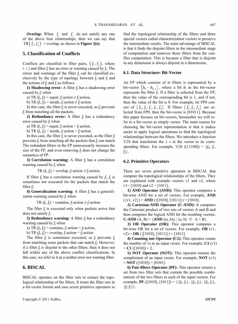
spaces required to find the relationship between the fil- ters. The basic difference in geometry and topology is that topology considers only the unique subspaces, whereas geometry considers all the subspaces. Therefore, the computation time and memory requirements for a topology-based approach are less than that of a geome- try-based approach. But in general, it is difficult to mathematically analyze the difference between the com- putation time and memory requirements in geometry and topology-based approaches. Therefore, we selected an example policy, FPA, which includes a lot of conflicts, with each and every filter is symmetrical to each other, and every filter conflicting with all the other filters. The two-dimensional spatial representation of FPA with 3 filters is shown in Figure 5(a) and m + 1 filter is shown in Figure 5(b).
In Figure 5(a), for sake of simplicity, we have repre- sented each sub
aces with the same filter sets (non-unique subspaces) are represented by a single numerical digit. For example, the number zero refers the subspace of filter f0, and the number four represents the subspace with filters {f1, f2}. Firstly, we compare the difference between the number of subspaces in Figure 5(a). The computation of con- flicts through topological approach requires only six subspaces, whereas the geometrical approach requires all thirteen subspaces for conflict detection. Likewise, if new filters are added by preserving the symmetrical structure, as shown in Figure 5(b), we derived the dif- ference in subspaces required for the topology and ge- ometry approaches for Figure 5.
When an m + 1th filter is added in FPA, the number of new subspaces increases by four
tal and there exists m + 1 number of unique subspaces following the sum of natural number series. Therefore in topological approach, when the m + 1th filter is added, the number of subspaces considered for conflict detec- tion is m + 1. However, in the geometrical approach, when the m + 1th filter is added, the total number of sub- spaces considered is four times the value of m. We can derive the following equations for the number of sub- spaces NSi for both approaches.
Topology:
2NS 2 m mi m
Copyright © 2011 SciRes. IJCNS
S. THANASEGARAN ET AL.
Copyright © 2011 SciRes. IJCNS
692
f0
f1
f2
X0
X1
0
0
21
5
2
1
4 4 33
1 1
f0
f1
X0
X1
fm+1
fm
...
(a) (b)
Figu and
re 5. FPA in two dimensions. (a) 3 filters; (b) m + 1 filters.
tional geometry-based approaches [7-9]. Our experiments were performed on Intel (R) Core
(TM) i5 750 @ 2.6 2.67 GHz w 00GM RAM g on Win profession con-
FPA FPB.
i iNS 1 NS 1 m m m . CPU 7 GHz ith 4.
runnin dows 7 al. We and
Geometry: ducted experiments with two policies, FPA is the policy discussed in the previo 22
iNS 1 m m m
us subsection, and FPB is a synthetic firewall policy, which is gener- ated by adding a large number of filters to a small prac- tical firewall. We have developed FPB based on the practical firewall policy being used in our lab. It consists of 99 packet filters of 5 dimensions, with 32-bit SrcIP, DesIP addresses, 16-bit SrcPort, DesPort numbers, and an 8-bit protocol. The synthetic firewall policy (FPB) ranges in size from 100 to 1000. In this paper, like other firewall management techniques [3-22], we did not con- sider the stateful filters for experimental evaluation. The treatment of conflict detection in stateful firewalls is a topic for future work. We conducted three experiments with both FPA and FPB.
Exp.1: Comparative performance analysis of topology and geometry [7-9] using FPA.
Exp.2: Evaluation of the system behavior in different scenarios by varying the ratio of wildcards in FPB.
Exp.3: Evaluation of
and
i iNS 1 NS 4 m m . m
We have substituted different values of , and tabu- lated the number of subspaces in Table 2. Our mathe- m
xperimental Analysis
y performing a compara- tive analysis between the proposed system and conven-
Numb y
m
atical analysis shows that the number of subspaces for the topology approach is nearly one-fourth of the geo- metrical approach in two-dimensional space. The differ- ence between the topology approach and the geometry approach is much larger when the dimension increases. In practical firewall policies, the efficiency of the topol- ogy approach is extremely high, because BISCAL re- moves the disjoint filters in the intermediate computation itself. We verify these using experiments in the next sec- tion.
8.2. Esystem behavior in practical
firewall policies by varying the number of filters in FPB. In the three experiments, we h
We have evaluated our system bave measured parame-
ters such as memory and computation time. Memory is compared by examining the number of subspaces
Table 2. Results of mathematical analysis. (NS)
required for conflict computation. Computation time is the measure of the program execution time until conflict er of filters Geometry Topolog
2 5 3
5 41 15
1 1 5
1000 1,998,001 500,500
00 9801 050
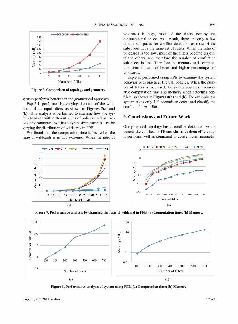
classification. We conducted three experiments, as shown above, and plotted graphs showing the number of filters on the x-axis, and the computation time expressed in seconds and memory expressed in KB and MB on the y-axis. The results of Exp.1 are shown in Figure 6. It is clear from the graph that our proposed topology-based
S. THANASEGARAN ET AL. 693
0
20
40
60
80
100
120
140
160
180y
(KB
)
5 10 15 20 25 30
Mem
ro
Number of filters
TOPOLOGY GEOMETRY
Figure 6. Comparison of topology and geometry. system performs better than the geometrical approach.
Exp.2 is performed by varying the ratio of the wild- cards of the input filters, as shown in Figures 7(a) nd (b). T sys-
m behaves with different kinds of polices used in vari- y
va
ahis analysis is performed to examine how the
teous environments. We have synthesized various FPs b
rying the distribution of wildcards in FPB. We found that the computation time is less when the
ratio of wildcards is in two extremes. When the ratio of
wildcards is high, most of the filters occupy the n-dimensional space. As a result, there are only a few unique subspaces for conflict detection, as most of the subspaces have the same set of filters. When the ratio of wildcards is too low, most of the filters become disjoint to the others, and therefore the number of conflicting subspaces is less. Therefore the memory and computa- tion time is less for lower and higher percentages of wildcards.
Exp.3 is performed using FPB to examine the system behavior with practical firewall policies. When the num- ber of filters is increased, the system requires a reason- able computation time and memory when detecting con- flicts, as shown in Figures 8(a) and (b). For example, the system takes only 100 seconds to detect and classify the conflicts for m = 500.
9. Conclusions and Future Work
Our proposed topology-based conflict detection system detects the conflicts in FP and classifies them efficiently. It performs well as compared to conventional geometri-
0.001
0.01
0.1
1
10
100
100 200 300 400 500 600 700 800 900 1000
Mem
ory
(MB
)
Number of filters
10% 30% 50% 70% 90%
(a) (b)
Figure 7. Performance analysis by changing the ratio of wildcard in FPB. (a) Computation time; (b) Memory.
0.1
1
10
100
1000
100 200 300 400 500 600 700
Com
puta
tion
time
(s)
Number of filters
0.01
0.1
1
10
100
100 200 300 400 500 600 700
Mem
ory
)
Number of filters
(M
B
(a) (b)
Figure 8. Performance analysis of system using FPB. (a) Computation time; (b) Memory.
Copyright © 2011 SciRes. IJCNS
S. THANASEGARAN ET AL. 694
cal approaches and efficiently utilizes the two important resources: computation time and memory. Our future research plan focuses on the detection of conflicts caused by combinations of filters in firewall policies and con- flict detection in stateful firewalls [28].
10. Acknowledgements
This research was partially supported by JSPS KAKENHI 23500085 and by the Hori Science and Art Foundation.
11. References
[1] The FreeBSDhttp://freebsd
Documentation Project, Ipfw, .org/doc/enUS.ISO88591/books/handbook/f
irewalls-ipfw.html
[2] A. Wool, “A Quantitative Study of firewall Configuration Errors,” Computer, Vol. 37, No. 6, 2004, pp. 62-67. doi:10.1109/MC.2004.2
[3] H. Hamed and A. I. Shaer, “Taxonomy of Conflicts in Network Security Policies,” IEEE Communications Maga-
. 134-141. 607877
zine, Vol. 44, No. 3, 2006, ppdoi:10.1109/MCOM.2006.1
itecting the Lumeta Firewall Analyzer,”the 10th conference on USENIX Security
Symposium, Berkeley, August 2001, pp. 85-97.
ransactions on Computers, Vol. 59,
[4] A. Mayer, A. Wool and E. Ziskind, “FANG: A Firewall Analysis Engine,” 2000 IEEE Symposium on Security and Privacy, Oakland, 14-17 May 2000, pp. 177-187.
[5] A. Wool, “ArchProceedings of
[6] M. Yoon, S. Chen and Z. Zhang, “Minimizing the Max-imum Firewall Rule Set in a Network with MultipleFirewalls,” IEEE T
No. 2, 2010, pp. 218-230. doi:10.1109/TC.2009.172
[7] D. Eppstein and S. Muthukrishnan, “Internet Packet FiManagement and Rectang
lterle Geometry,” Proceedings
i, “Detection of of Filters Based on
a-
Security
n Firewall Poli-
Analysis of Distributed Firewall Policies,” IEEE Journal on Selected Areas in Communications, Vol. 23, No. 10, 2005, pp. 2069-2084. doi:10.1109/JSAC.2005.854119
[13] V. Capretta, B. Stepien, A. Felty and S. Matwin, “Formal Correctness of Conflict Detection for Firewalls,” Pro- ceedings of the 2007 ACM Workshop on Formal Methods in Security Engineering, Virginia, November 2007, pp. 22-30.
[14] H. K. Verizon and K. A. Ahmat, “Fast and Scalable Me- thod for Resolving Anomalies in Firewall Policies,” 14th IEEE Global Internet Symposium 2011, Shanghai, 15 April 2011, pp. 839-844.
lkarni, “FAME: A Firewall vironment,” 3rd ACM Work-
ity Configuration,
Redundancy
,” in Japanese, The Informa-
A Toolkit for Firewall Modeling and Ana-
ee
, S. Suri and G. Parulkar, “Detecting and Resolv-
of the
12th Annual ACM-SIAM Symposium on Discrete Algo- rithms, Washington, 2001, pp. 827-835.
[8] Y. Yin, Y. Katayama and N. TakahashConflicts Caused by a CombinationsSpatial Relationships,” The Information Processing Soci- ety of Japan, Vol. 49, 2008, pp. 3121-3135.
[9] Y. Yin, R. S. Bhuvaneswaran, Y. Katayama and N. T kahashi, “Implementation of Packet Filter Configurations Anomaly Detection System with SIERRA,” International Conference on Information and Communication , Beijing, 2005, pp. 467-480.
[10] T. Subana, Y. Yin, Y. Tateiwa, Y. Katayama and N. Ta-kahashi, “A Topological Approach to Detect Conflicts in Firewall Policies,” 2009 IEEE International Symposium on Parallel & Distributed Processing, Rome, May 2009.
[11] T. Subana, Y. Yin, Y. Tateiwa, Y. Katayama and N. Ta- kahashi, “BISCAL: A Bit-Vector Based Spatial Calculus for Analyzing the Mis-Configurations i cies,” IEICE Technical Report, Vol. 108, No. 409, 2009, pp. 101-106.
[12] E. Al-Shaer and H. Hamed, “Conflict Classification and
[15] H. Hu, G. J. Ahn and K. KuAnomaly Management Enshop on Assurable and Usable SecurChicago, October 2010, pp. 17-26.
[16] A. X. Liu and M. G. Goudam, “Complete Detection in Firewalls,” Proceeding of 19th Annual IFIP Conference on Data and Applications Security, Storrs, 2005, pp. 196-209.
[17] K. Matsuda, “A Packet Filtering Rules Compression by Decomposing into Matrixestion Processing Society of Japan, Vol. 48, No. 10, 2007, pp. 3357-3364.
[18] K. Golnabi, R. K. Min, L. Khan, and E. Al. Shaer, “Analysis of Firewall Policy Rules Using Data MiningTechniques,” 10th IEEE/IFIP Network Operations and Management Symposium, Vancouver, 3-7 April 2006, pp. 305-315.
[19] L. Yuan, J. Mai, Z. Su, H. Chen and P. Mohapatra, “FIREMAN: lysis,” Proceeding of 2006 IEEE Symposium on Security and Privacy, Oakland, 21-24 May 2006, pp. 199-213.
[20] B. Zhang, E. AI. Shaer, R. Jagadeesan, J. Riely and C. Pitcher, “Specifications of a High-Level Conflict-FrFirewall Policy Language for Multi-Domain Networks,” Proceedings of the 12th ACM Symposium on Access con-trol Models and Technologies, Sophia Antipolis, 20- 22 June 2007, pp. 185-194.
[21] A. Hariing Packet Filter Conflicts,” Proceeding of 19th Annual Joint Conference of the IEEE Computer and Communi- cations Societies, Tel Aviv, 26-30 March 2000, pp. 1203-1212.
[22] F. Baboescu and G. Varghese, “Fast and Scalable Con- flict Detection for Packet Classifiers,” 10th IEEE Inter- national Conference on Network Protocols, Paris, 12-15 November 2002, pp. 270-279. doi:10.1109/ICNP.2002.1181414
[23] N. Takahashi, “A Systolic Sieve Array for Real-Time Packet Classification,” The Information Processing Soci- ety of Japan, Vol. 42, No. 2, 2001, pp. 146-166.
del,” Proceedings of the international symposium on Parallel Computing in Electrical Engi-
[24] T. Srinivasan, N. Dhanasekar, M. Nivedita, R. Dhivya- krishnan and A. A. Azeezunnisa, “Scalable and Parallel Aggregated Bitvector Packet Classification Using Prefix Computation Mo
Copyright © 2011 SciRes. IJCNS

S. THANASEGARAN ET AL. 695
ations, Technologies, Architectures, and Pro-
ed-
,
Binary Topo-
neering, Bialystok, 13-17 September 2006, pp. 139-144.
[25] T. V. Lakshman, “High-Speed Policy Based Packet For- warding Using Efficient Multi-Dimensional Range Match- ing,” Proceedings of the ACM SIGCOMM’98 Conference on Applic
Augu
tocols for Computer Communication, Vancouver, 2-4 September 1998, pp. 203-214.
[26] S. Singh, F. Baboescu, G. Varghese and J. Wang, “Packet Classification Using Multidimensional Cutting,” Proceings of the 2003 Conference on Applications, Technologies, Architectures, and Protocols for Computer Communica- tions, Karsruhe, 7 February 2003, pp. 213-224.
[27] M. Buddhikot, S. Suri and M. Waldvogel, “Space De- composition Techniques for Fast Layer-4 Switching,” Proceedings: Protocols for High-Speed Networks, Salem
st 1999, pp. 25-42.
[28] K. Hida, Y. Katayama and N. Takahashi, “A Filter Re- verse Search System for LANs with Stateful Firewalls,” IEICE Technical Report, Vol. 107, No. 483, 2007, pp. 65-70.
[29] Max J. Egenhofer, “A Formal Definition oflogical Relationships,” 3rd International Conference on Foundations of Data Organization and Algorithms, Vol. 367, 1989, pp. 457-472.
Copyright © 2011 SciRes. IJCNS


![:: Protecting your infrastructure · Proxy Filter (Content Filtering, URLFiltering, WebAntivirus [AV]) UNLIMITED USERS . VPN FIREWALL CONTENT FILTERING IDPS Features TRAFFIC SHAPER](https://img.pdfslide.us/doc/110x75/5f035fea7e708231d408e6d7/-protecting-your-infrastructure-proxy-filter-content-filtering-urlfiltering.jpg)


![A Virtual Firewall Mechanism Using Army Nodes to Protect Cloud … firewall... · 2015-05-01 · cloud resources. Handling DDoS [7] requires filtering the flooding attack and processing](https://img.pdfslide.us/doc/110x75/5ed3d752cd225536e01de722/a-virtual-firewall-mechanism-using-army-nodes-to-protect-cloud-firewall-2015-05-01.jpg)