Embed Size (px)
Citation preview
A TOOLKIT FOR THE DESIGN OF AMBISONIC DECODERS
Aaron J. Heller, SRI International, Menlo Park, CA US Eric M. Benjamin, Surround Research, Pacifica, CA US Richard Lee, Pandit Litoral, Cooktown, QLD AU
Linux Audio Conference, April 13, 2012
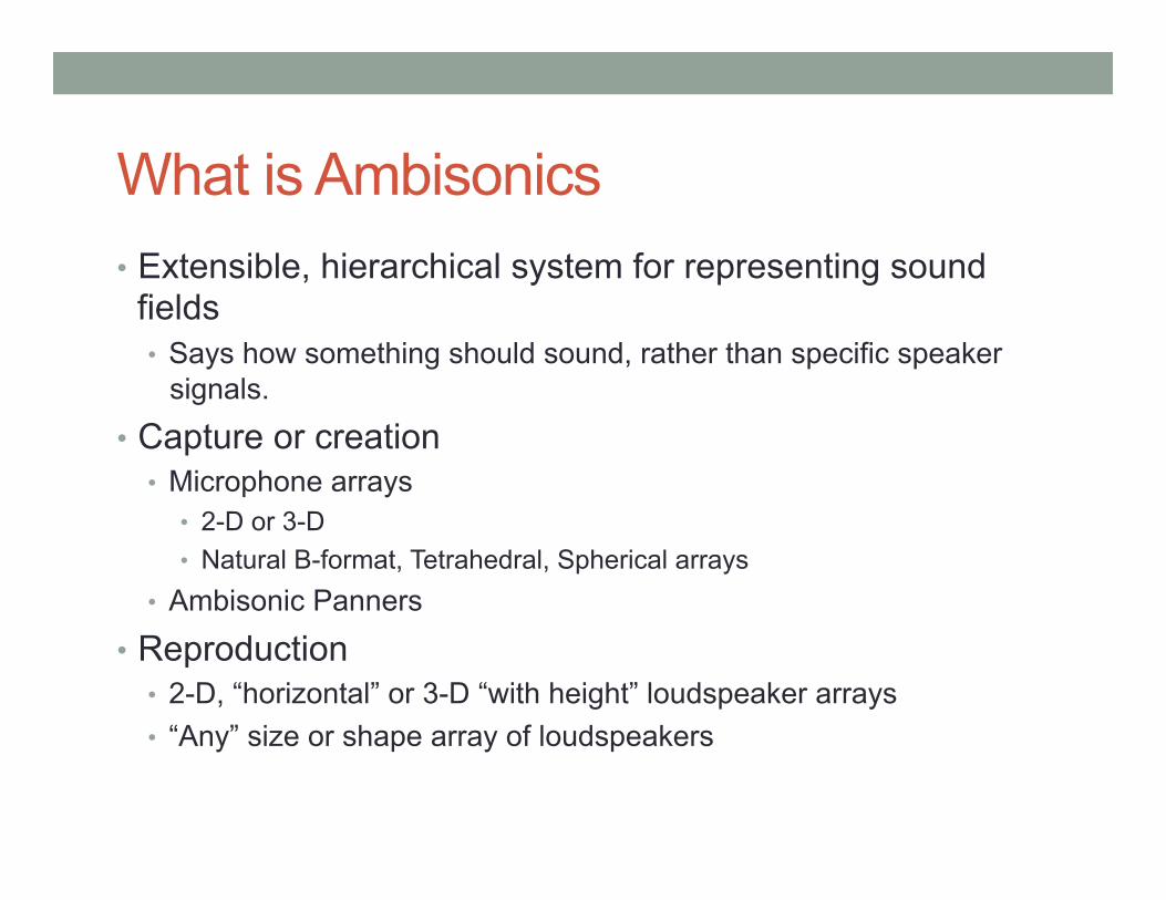
What is Ambisonics • Extensible, hierarchical system for representing sound
fields • Says how something should sound, rather than specific speaker
signals.
• Capture or creation • Microphone arrays
• 2-D or 3-D • Natural B-format, Tetrahedral, Spherical arrays
• Ambisonic Panners
• Reproduction • 2-D, “horizontal” or 3-D “with height” loudspeaker arrays • “Any” size or shape array of loudspeakers
Extensible? • Ambisonics was originally implemented as first order,
although always conceived as a hierarchical system • More recently, various system have worked with as high
as 5th order. • CCRMA Listening Room works with signals up to 3rd order
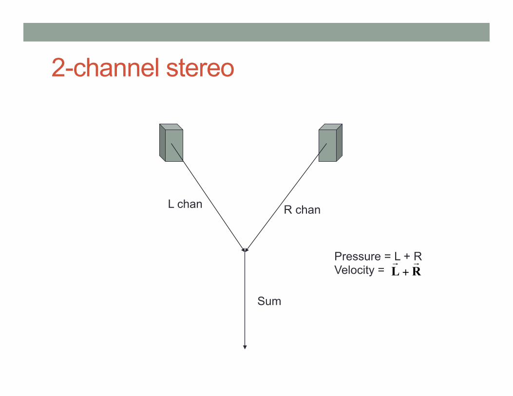
2-channel stereo
L chan R chan
Sum
Pressure = L + R Velocity = RL
+
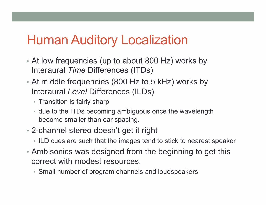
Human Auditory Localization • At low frequencies (up to about 800 Hz) works by
Interaural Time Differences (ITDs) • At middle frequencies (800 Hz to 5 kHz) works by
Interaural Level Differences (ILDs) • Transition is fairly sharp • due to the ITDs becoming ambiguous once the wavelength
become smaller than ear spacing.
• 2-channel stereo doesn’t get it right • ILD cues are such that the images tend to stick to nearest speaker
• Ambisonics was designed from the beginning to get this correct with modest resources. • Small number of program channels and loudspeakers
Gerzon’s Theory of Auditory Localization • Early workers in stereo did theoretical analysis showing
how stereo did (or didn’t) provide proper localization cues • Gerzon’s contribution was to integrate those theories and
came up with a theory that defined • rV, the vector sum of the signals from the loudspeakers • rE, the vector sum of the squares of the signals from the
loudspeakers.
• By providing a simple mathematical encapsulation, we can use these to • design decoders • prove theorems, e.g., polygonal decoder theorem • help understand what various spatial sound reproduction systems
can and cannot do
Localization Vector Theory • rV predicts low-frequency localization almost perfectly.
• If rV=1, then low-frequency sounds will be precisely located.
• rE predicts mid-frequency localization moderately well. • If rE=1, then mid-frequency localization will be good • BUT… rE is always less than1, unless the sound is coming from a
single point source. • At best rE = cos(θ/2), where θ is the angle between the
loudspeakers, so for a square array rE ≤ 0.707. • In general, rE is low in directions with few loudspeakers • Best we can do is have it change smoothly in performance from
dense areas to sparse areas.
Energy Localization Vector • Maximizing rE and getting it to point in the right direction is
the crux of the decoder design problem. • Easy with regular arrays • Irregular arrays always involve tradeoffs • Virtually all real world arrays are irregular!
• Arrays need to fit in real rooms • ITU 5.1 is the dominant domestic standard, rear speakers 120° apart.
• Because it is a non-linear function of speaker position, we currently need to use numerical optimization methods.
What is a Decoder • In Ambisonics, the program format is independent of the
reproduction layout. • The decoder’s task is to create the best perceptual
impression possible that the sound field is being reproduced accurately, given the resources available • Bandwidth, number of speakers, configuration of speakers …
• We use the term “decoder” to mean the configuration for a decoding engine that does the actual signal processing • E.g., Ambdec
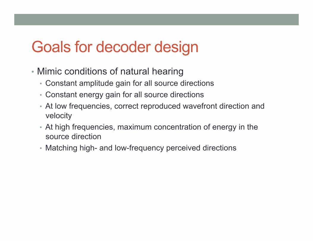
Goals for decoder design • Mimic conditions of natural hearing
• Constant amplitude gain for all source directions • Constant energy gain for all source directions • At low frequencies, correct reproduced wavefront direction and
velocity • At high frequencies, maximum concentration of energy in the
source direction • Matching high- and low-frequency perceived directions
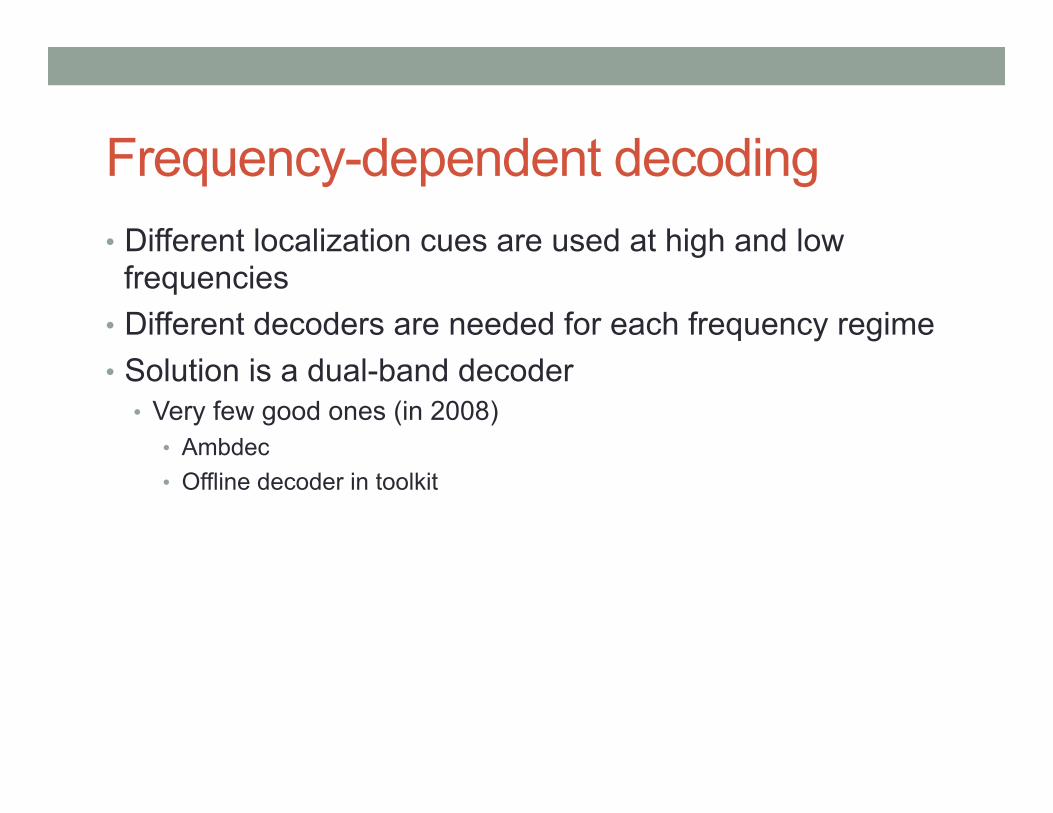
Frequency-dependent decoding • Different localization cues are used at high and low
frequencies • Different decoders are needed for each frequency regime • Solution is a dual-band decoder
• Very few good ones (in 2008) • Ambdec • Offline decoder in toolkit
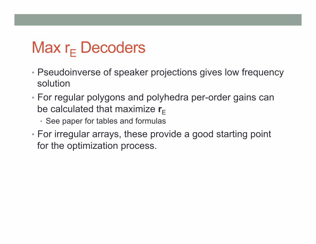
Max rE Decoders • Pseudoinverse of speaker projections gives low frequency
solution • For regular polygons and polyhedra per-order gains can
be calculated that maximize rE • See paper for tables and formulas
• For irregular arrays, these provide a good starting point for the optimization process.
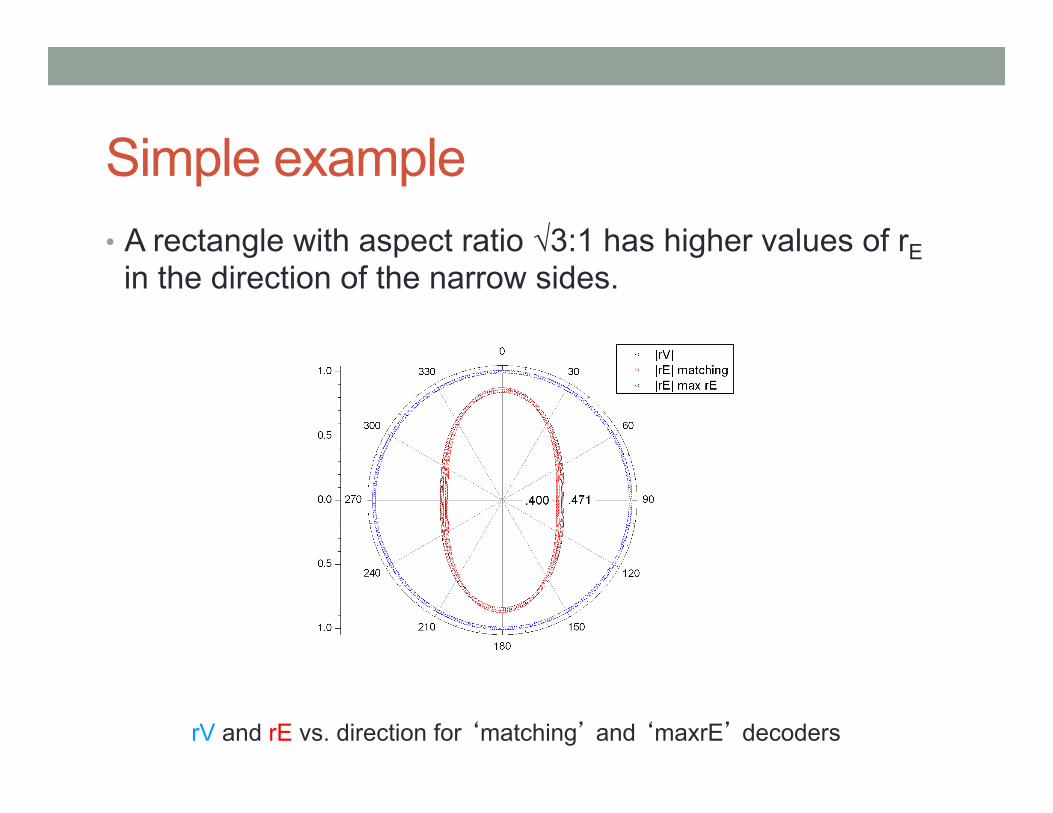
Simple example • A rectangle with aspect ratio √3:1 has higher values of rE
in the direction of the narrow sides.
rV and rE vs. direction for ‘matching’ and ‘maxrE’ decoders
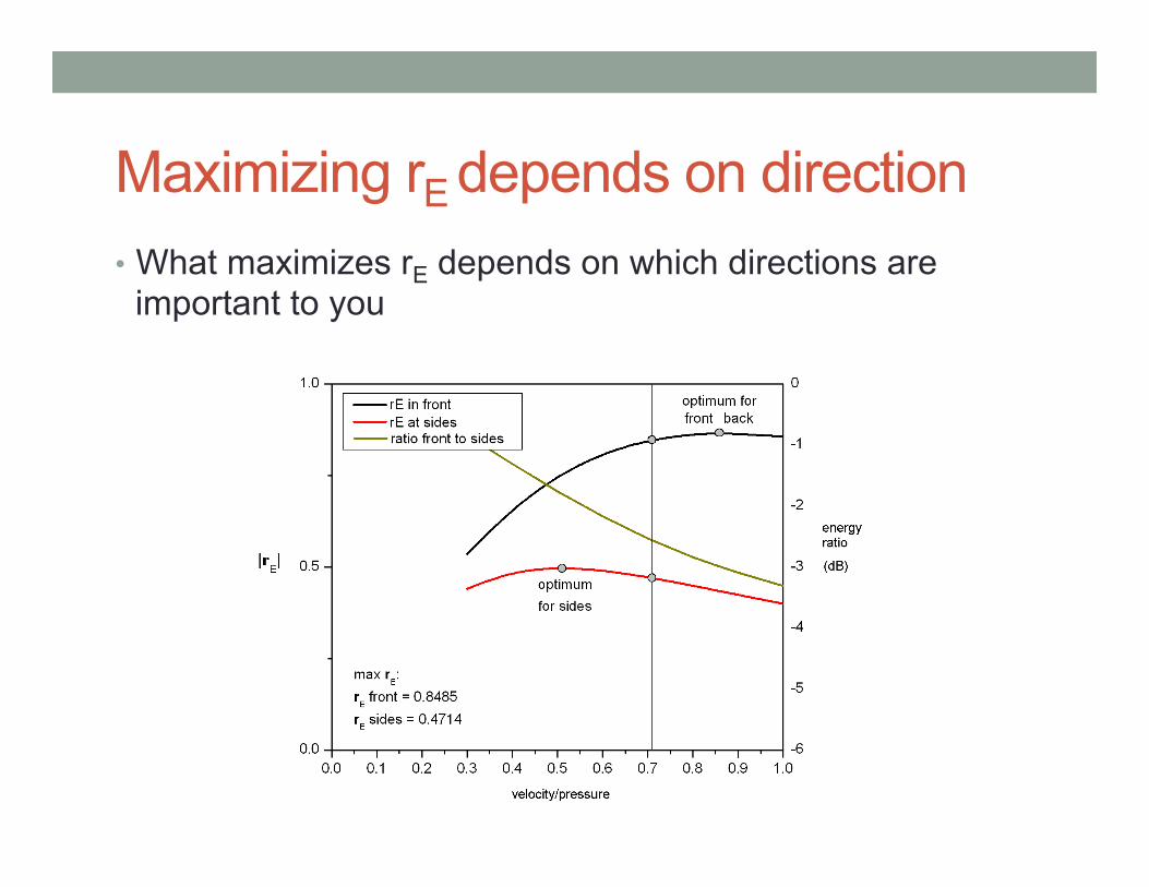
Maximizing rE depends on direction • What maximizes rE depends on which directions are
important to you
Optimization • With irregular arrays, simply scaling the LF and HF
matrices does not result in rv and rE pointing in the same direction
• Key psychoacoustic criteria for good reproduction are non-linear functions of speaker locations, so we need to use numerical optimization techniques.
• We use the NLOpt library for nonlinear optimization • Free and open source • Provides a common API to a number of algorithms • Supports a number of local and global “derivative free” optimization
algorithms.
Optimization Criteria • For each test direction, we compute
• Amplitude gain, P • Energy gain, E • Velocity localization vector, rV • Energy localization vector, rE
• Summarize • Deviation of amplitude gain from 1 along the X-axis • Minimum, maximum, and RMS values of
• Amplitude gain • Energy gain • Magnitude of rV • Magnitude of rE • Pairwise angular deviations of rV, rE, and source direction
• Weighted sum to compute single figure of merit, which is minimized • Directional weighting possible • Soft limits
Test Directions • Each candidate set of parameters is evaluated from a
number of directions • 2D, 180 or 360 evenly spaced directions • 3D, no more than 20 points can be distributed uniformly on a
sphere
• Lebedev-Laikov quadrature • Defines sets of points and weights that provide exact results for
integration of spherical harmonics • Current implementation uses 2702 points, roughly 3° spacing.
• Toolkit also provides grids sampled in uniform azimuth and elevation increments – useful for visualization.
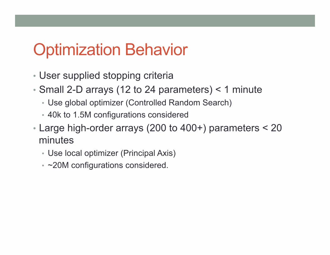
Optimization Behavior • User supplied stopping criteria • Small 2-D arrays (12 to 24 parameters) < 1 minute
• Use global optimizer (Controlled Random Search) • 40k to 1.5M configurations considered
• Large high-order arrays (200 to 400+) parameters < 20 minutes • Use local optimizer (Principal Axis) • ~20M configurations considered.
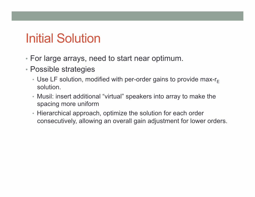
Initial Solution • For large arrays, need to start near optimum. • Possible strategies
• Use LF solution, modified with per-order gains to provide max-rE solution.
• Musil: insert additional “virtual” speakers into array to make the spacing more uniform
• Hierarchical approach, optimize the solution for each order consecutively, allowing an overall gain adjustment for lower orders.
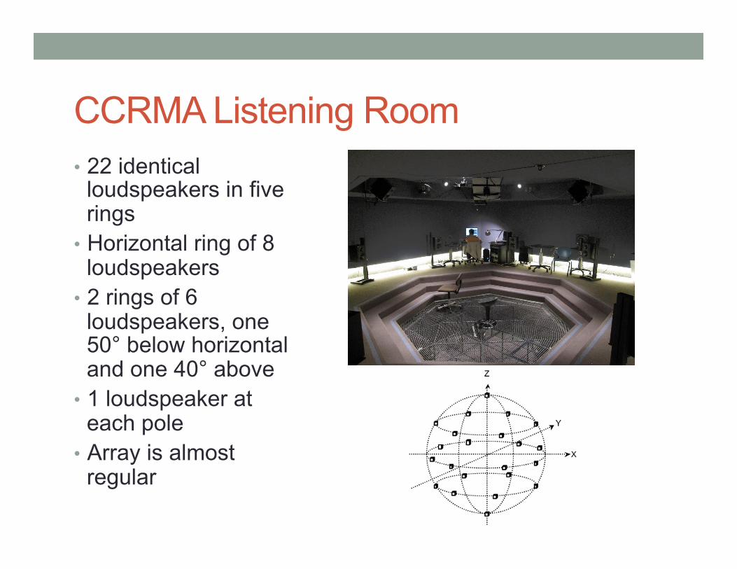
CCRMA Listening Room • 22 identical
loudspeakers in five rings
• Horizontal ring of 8 loudspeakers
• 2 rings of 6 loudspeakers, one 50° below horizontal and one 40° above
• 1 loudspeaker at each pole
• Array is almost regular
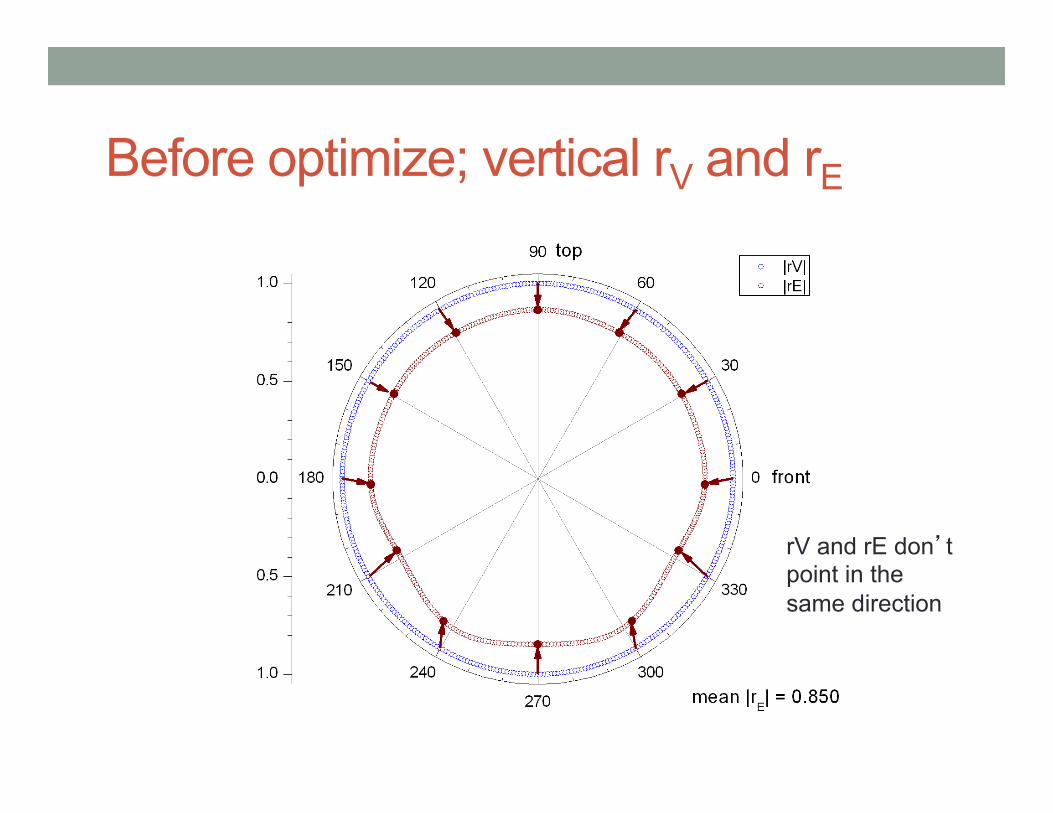
Before optimize; vertical rV and rE
rV and rE don’t point in the same direction
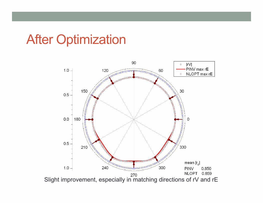
After Optimization
Slight improvement, especially in matching directions of rV and rE
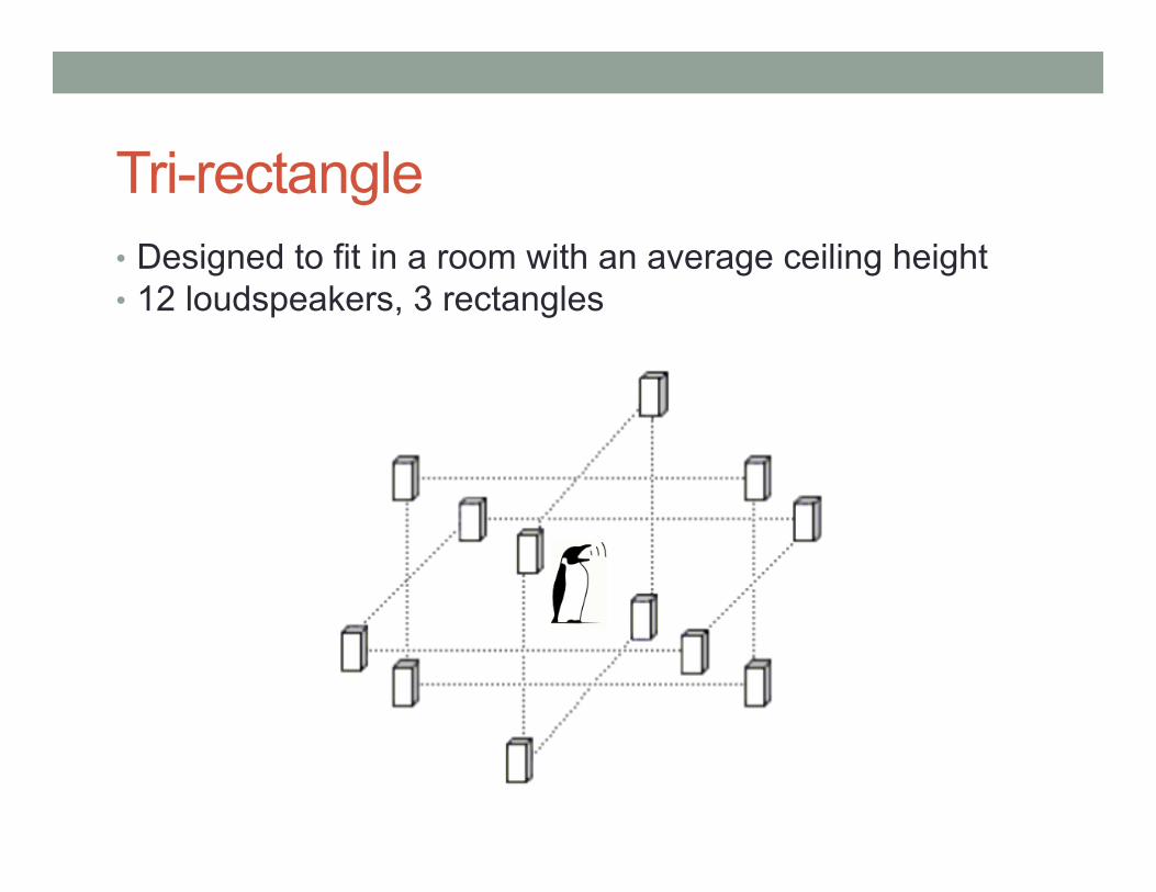
Tri-rectangle • Designed to fit in a room with an average ceiling height • 12 loudspeakers, 3 rectangles
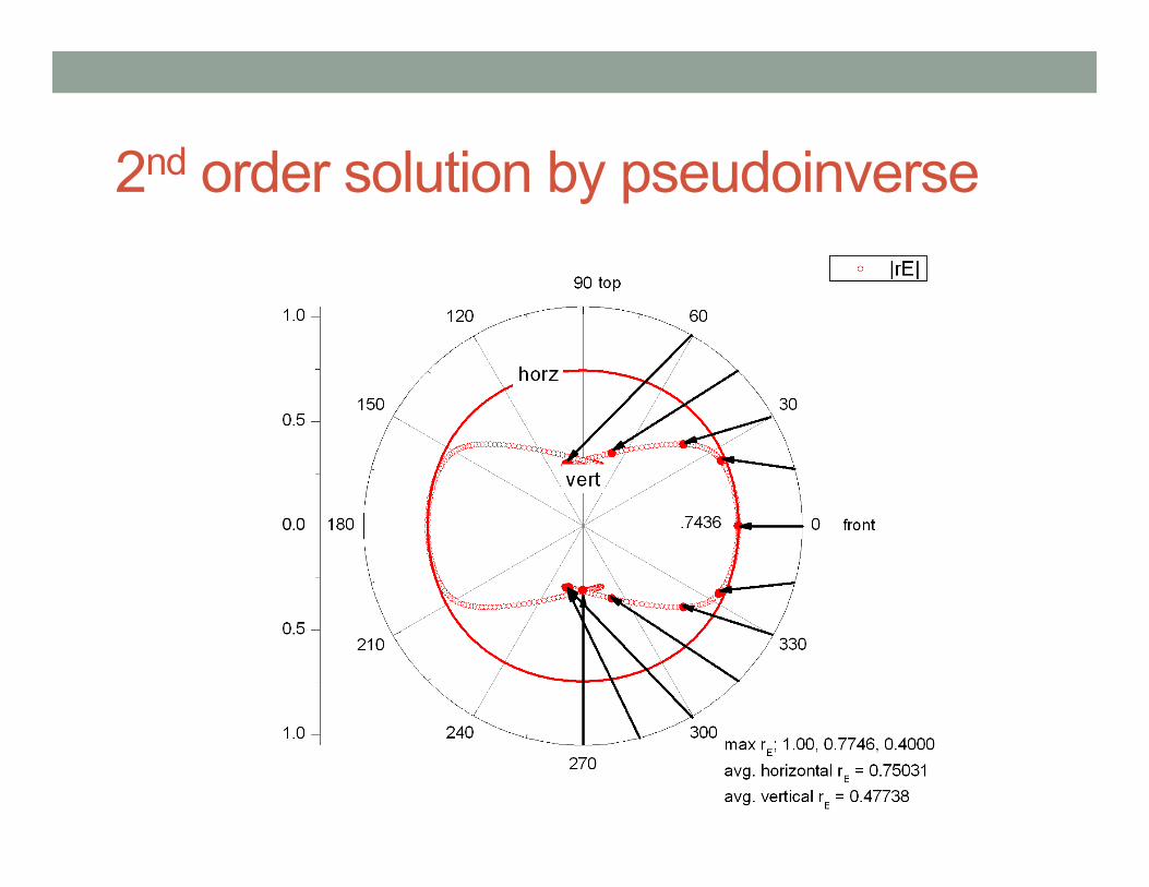
2nd order solution by pseudoinverse
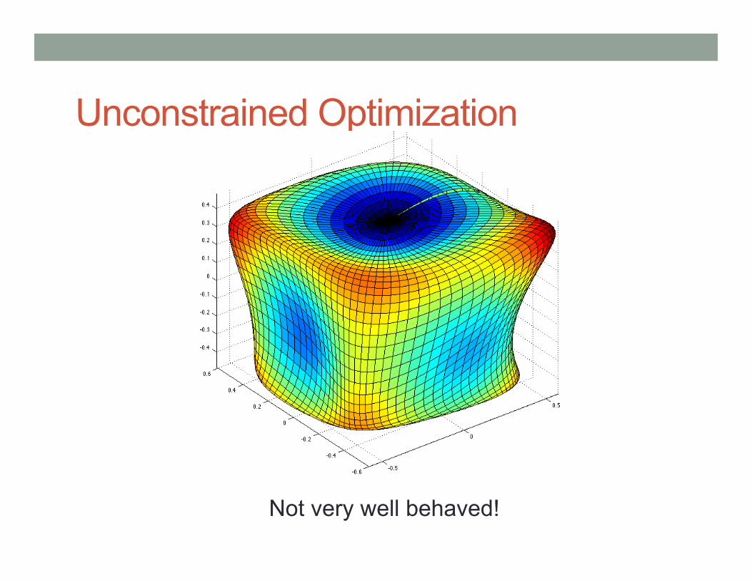
Unconstrained Optimization
Not very well behaved!
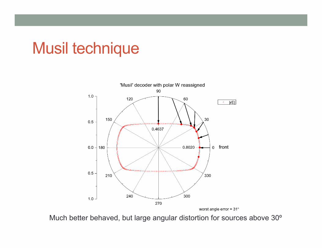
Musil technique
Much better behaved, but large angular distortion for sources above 30º
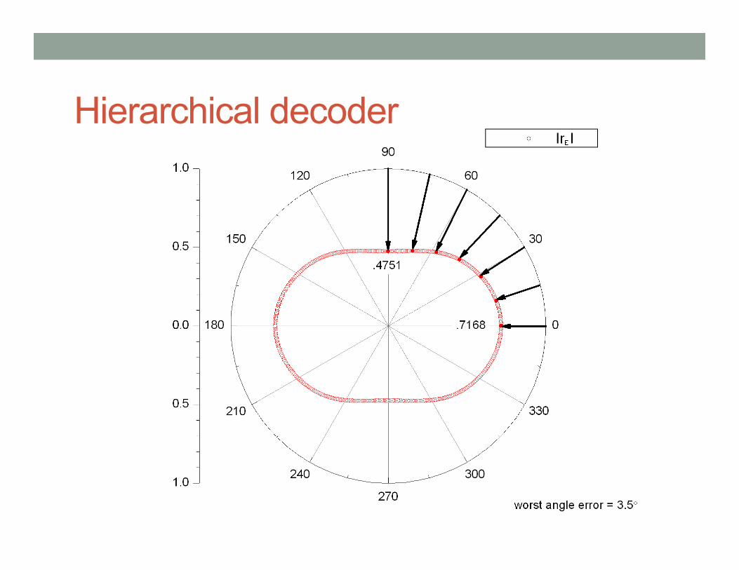
Hierarchical decoder
Implementation • Toolkit is implemented in Gnu Octave
• Runs in MATLAB too. (about 2x faster) • Older 2-D version in C++, but performance almost as fast. • Most of computation is matrix multiplication
• CUDA version possible • Used to design current decoder for CCRMA Listening
Room • Includes
• Tools for regular arrays • Nonlinear optimizer • Reference offline decoder • Output functions for Ambdec config files
• Beta release in early May.
Summary • Toolkit for design of HOA decoders for irregular arrays
• Implements multiple strategies
• Good results • Need good initial solution for large arrays
• Open problems • LF/HF matching • Automated evaluation of initial conditions and result

Thanks! • Fernando for giving us the challenge of designing a new
decoder for the Listening Room. • LAC 2012 organizers • CCRMA • Linux community


![VRIF Guidelines 2 · 2020. 6. 4. · Amendment Enhancements for High Efficiency WLAN (IEEE 802.11ax) [ACN] Ambisonic data exchange formats – Ambisonic Channel Number (Wikipedia)](https://img.pdfslide.us/doc/110x75/5fc06d1b5a042e3fdb268930/vrif-guidelines-2-2020-6-4-amendment-enhancements-for-high-efficiency-wlan.jpg)
![Welcome [lac.linuxaudio.org]lac.linuxaudio.org/2014/download/Meet_MOD.pdf · Welcome Gianfranco Ceccolini – CEO at Musical Operating Devices – Mechanical engineer – Guitar player](https://img.pdfslide.us/doc/110x75/5e80ad09bba5de40071285fa/welcome-lac-lac-welcome-gianfranco-ceccolini-a-ceo-at-musical-operating-devices.jpg)