Embed Size (px)
Citation preview
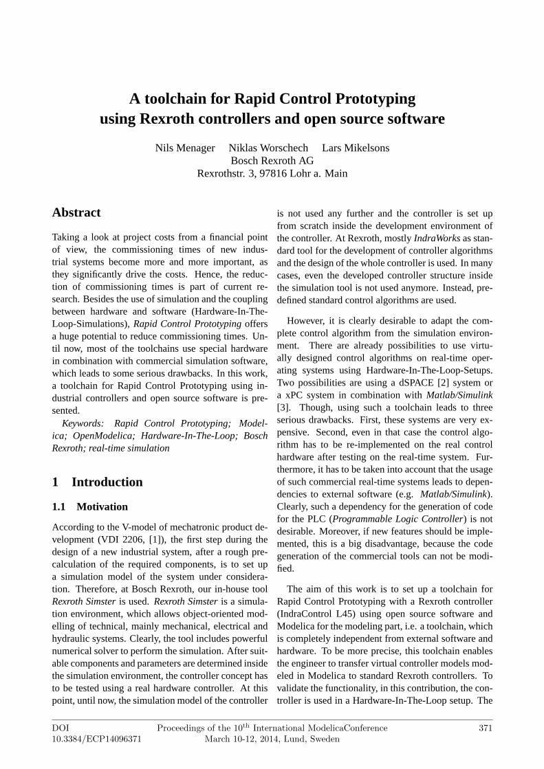
A toolchain for Rapid Control Prototypingusing Rexroth controllers and open source software
Nils Menager Niklas Worschech Lars MikelsonsBosch Rexroth AG
Rexrothstr. 3, 97816 Lohr a. Main
Abstract
Taking a look at project costs from a financial pointof view, the commissioning times of new indus-trial systems become more and more important, asthey significantly drive the costs. Hence, the reduc-tion of commissioning times is part of current re-search. Besides the use of simulation and the couplingbetween hardware and software (Hardware-In-The-Loop-Simulations),Rapid Control Prototyping offersa huge potential to reduce commissioning times. Un-til now, most of the toolchains use special hardwarein combination with commercial simulation software,which leads to some serious drawbacks. In this work,a toolchain for Rapid Control Prototyping using in-dustrial controllers and open source software is pre-sented.
Keywords: Rapid Control Prototyping; Model-ica; OpenModelica; Hardware-In-The-Loop; BoschRexroth; real-time simulation
1 Introduction
1.1 Motivation
According to the V-model of mechatronic product de-velopment (VDI 2206, [1]), the first step during thedesign of a new industrial system, after a rough pre-calculation of the required components, is to set upa simulation model of the system under considera-tion. Therefore, at Bosch Rexroth, our in-house toolRexroth Simster is used.Rexroth Simster is a simula-tion environment, which allows object-oriented mod-elling of technical, mainly mechanical, electrical andhydraulic systems. Clearly, the tool includes powerfulnumerical solver to perform the simulation. After suit-able components and parameters are determined insidethe simulation environment, the controller concept hasto be tested using a real hardware controller. At thispoint, until now, the simulation model of the controller
is not used any further and the controller is set upfrom scratch inside the development environment ofthe controller. At Rexroth, mostlyIndraWorks as stan-dard tool for the development of controller algorithmsand the design of the whole controller is used. In manycases, even the developed controller structure insidethe simulation tool is not used anymore. Instead, pre-defined standard control algorithms are used.
However, it is clearly desirable to adapt the com-plete control algorithm from the simulation environ-ment. There are already possibilities to use virtu-ally designed control algorithms on real-time oper-ating systems using Hardware-In-The-Loop-Setups.Two possibilities are using a dSPACE [2] system ora xPC system in combination withMatlab/Simulink[3]. Though, using such a toolchain leads to threeserious drawbacks. First, these systems are very ex-pensive. Second, even in that case the control algo-rithm has to be re-implemented on the real controlhardware after testing on the real-time system. Fur-thermore, it has to be taken into account that the usageof such commercial real-time systems leads to depen-dencies to external software (e.g.Matlab/Simulink).Clearly, such a dependency for the generation of codefor the PLC (Programmable Logic Controller) is notdesirable. Moreover, if new features should be imple-mented, this is a big disadvantage, because the codegeneration of the commercial tools can not be modi-fied.
The aim of this work is to set up a toolchain forRapid Control Prototyping with a Rexroth controller(IndraControl L45) using open source software andModelica for the modeling part, i.e. a toolchain, whichis completely independent from external software andhardware. To be more precise, this toolchain enablesthe engineer to transfer virtual controller models mod-eled in Modelica to standard Rexroth controllers. Tovalidate the functionality, in this contribution, the con-troller is used in a Hardware-In-The-Loop setup. The
DOI10.3384/ECP14096371
Proceedings of the 10th International ModelicaConferenceMarch 10-12, 2014, Lund, Sweden
371
validation of the controller in combination with a realsystem is part of current work.
1.2 Outline of this paper
In the first section of this paper, a short introductioninto Rapid Control Prototyping is given. Furthermore,a standard toolchain for using Rapid Control Proto-typing nowadays is discussed. In the second section,after requirements for the toolchain have been defined,the specific parts of the toolchain are presented. Thefunctionality of the toolchain is finally verified usinga Hardware-In-The-Loop setup consisting of a realRexroth hardware controller running controller codeof an industrial control algorithm created in Modelicaand a model of a hydro-mechanic system. In the lastpart, a short summary and an outlook on further inves-tigation is presented.
2 Rapid Control Prototyping
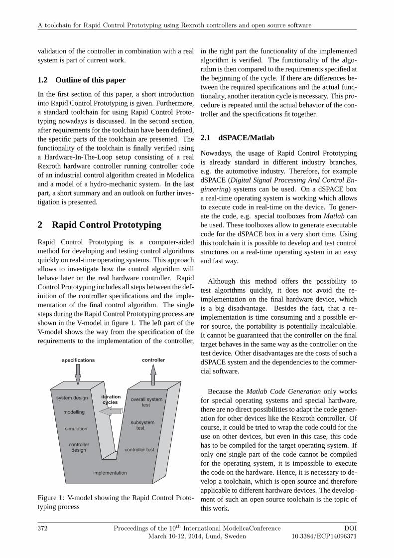
Rapid Control Prototyping is a computer-aidedmethod for developing and testing control algorithmsquickly on real-time operating systems. This approachallows to investigate how the control algorithm willbehave later on the real hardware controller. RapidControl Prototyping includes all steps between the def-inition of the controller specifications and the imple-mentation of the final control algorithm. The singlesteps during the Rapid Control Prototyping process areshown in the V-model in figure 1. The left part of theV-model shows the way from the specification of therequirements to the implementation of the controller,
specifications controller
implementation
controller test
subsystemtest
overall systemtest
system design
modelling
simulation
controllerdesign
iterationcycles
Figure 1: V-model showing the Rapid Control Proto-typing process
in the right part the functionality of the implementedalgorithm is verified. The functionality of the algo-rithm is then compared to the requirements specified atthe beginning of the cycle. If there are differences be-tween the required specifications and the actual func-tionality, another iteration cycle is necessary. This pro-cedure is repeated until the actual behavior of the con-troller and the specifications fit together.
2.1 dSPACE/Matlab
Nowadays, the usage of Rapid Control Prototypingis already standard in different industry branches,e.g. the automotive industry. Therefore, for exampledSPACE (Digital Signal Processing And Control En-gineering) systems can be used. On a dSPACE boxa real-time operating system is working which allowsto execute code in real-time on the device. To gener-ate the code, e.g. special toolboxes fromMatlab canbe used. These toolboxes allow to generate executablecode for the dSPACE box in a very short time. Usingthis toolchain it is possible to develop and test controlstructures on a real-time operating system in an easyand fast way.
Although this method offers the possibility totest algorithms quickly, it does not avoid the re-implementation on the final hardware device, whichis a big disadvantage. Besides the fact, that a re-implementation is time consuming and a possible er-ror source, the portability is potentially incalculable.It cannot be guaranteed that the controller on the finaltarget behaves in the same way as the controller on thetest device. Other disadvantages are the costs of such adSPACE system and the dependencies to the commer-cial software.
Because theMatlab Code Generation only worksfor special operating systems and special hardware,there are no direct possibilities to adapt the code gener-ation for other devices like the Rexroth controller. Ofcourse, it could be tried to wrap the code could for theuse on other devices, but even in this case, this codehas to be compiled for the target operating system. Ifonly one single part of the code cannot be compiledfor the operating system, it is impossible to executethe code on the hardware. Hence, it is necessary to de-velop a toolchain, which is open source and thereforeapplicable to different hardware devices. The develop-ment of such an open source toolchain is the topic ofthis work.
A toolchain for Rapid Control Prototyping using Rexroth controllers and open source software
372 Proceedings of the 10th International ModelicaConferenceMarch 10-12, 2014, Lund, Sweden
DOI10.3384/ECP14096371
3 Realization of the toolchain
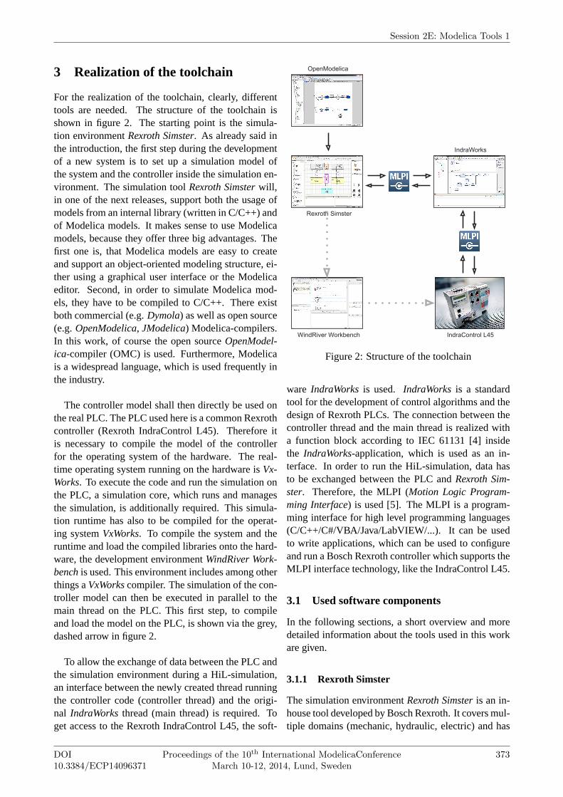
For the realization of the toolchain, clearly, differenttools are needed. The structure of the toolchain isshown in figure 2. The starting point is the simula-tion environmentRexroth Simster. As already said inthe introduction, the first step during the developmentof a new system is to set up a simulation model ofthe system and the controller inside the simulation en-vironment. The simulation toolRexroth Simster will,in one of the next releases, support both the usage ofmodels from an internal library (written in C/C++) andof Modelica models. It makes sense to use Modelicamodels, because they offer three big advantages. Thefirst one is, that Modelica models are easy to createand support an object-oriented modeling structure, ei-ther using a graphical user interface or the Modelicaeditor. Second, in order to simulate Modelica mod-els, they have to be compiled to C/C++. There existboth commercial (e.g.Dymola) as well as open source(e.g.OpenModelica, JModelica) Modelica-compilers.In this work, of course the open sourceOpenModel-ica-compiler (OMC) is used. Furthermore, Modelicais a widespread language, which is used frequently inthe industry.
The controller model shall then directly be used onthe real PLC. The PLC used here is a common Rexrothcontroller (Rexroth IndraControl L45). Therefore itis necessary to compile the model of the controllerfor the operating system of the hardware. The real-time operating system running on the hardware isVx-Works. To execute the code and run the simulation onthe PLC, a simulation core, which runs and managesthe simulation, is additionally required. This simula-tion runtime has also to be compiled for the operat-ing systemVxWorks. To compile the system and theruntime and load the compiled libraries onto the hard-ware, the development environmentWindRiver Work-bench is used. This environment includes among otherthings aVxWorks compiler. The simulation of the con-troller model can then be executed in parallel to themain thread on the PLC. This first step, to compileand load the model on the PLC, is shown via the grey,dashed arrow in figure 2.
To allow the exchange of data between the PLC andthe simulation environment during a HiL-simulation,an interface between the newly created thread runningthe controller code (controller thread) and the origi-nal IndraWorks thread (main thread) is required. Toget access to the Rexroth IndraControl L45, the soft-
Figure 2: Structure of the toolchain
ware IndraWorks is used. IndraWorks is a standardtool for the development of control algorithms and thedesign of Rexroth PLCs. The connection between thecontroller thread and the main thread is realized witha function block according to IEC 61131 [4] insidethe IndraWorks-application, which is used as an in-terface. In order to run the HiL-simulation, data hasto be exchanged between the PLC andRexroth Sim-ster. Therefore, the MLPI (Motion Logic Program-ming Interface) is used [5]. The MLPI is a program-ming interface for high level programming languages(C/C++/C#/VBA/Java/LabVIEW/...). It can be usedto write applications, which can be used to configureand run a Bosch Rexroth controller which supports theMLPI interface technology, like the IndraControl L45.
3.1 Used software components
In the following sections, a short overview and moredetailed information about the tools used in this workare given.
3.1.1 Rexroth Simster
The simulation environmentRexroth Simster is an in-house tool developed by Bosch Rexroth. It covers mul-tiple domains (mechanic, hydraulic, electric) and has
Session 2E: Modelica Tools 1
DOI10.3384/ECP14096371
Proceedings of the 10th International ModelicaConferenceMarch 10-12, 2014, Lund, Sweden
373
been developed for the design and optimization of con-trolled automation systems. The component library in-cludes both generic and Rexroth specific components,which can simply be placed on the worksheet usingdrag and drop.Rexroth Simster includes a special sim-ulation core. This simulation core offers an interfacefor models from the standardSimster libraries, whichare implemented in C/C++. The C/C++ code gener-ated by theOpenModelica-compiler implements thesame interface. Thus, the simulation core can handleboth models from the own internal library and Model-ica models. Detailed information about the developedsimulation runtime is given in [6].
3.1.2 WindRiver Workbench
WindRiver Workbench is an eclipse-based develop-ment environment forVxWorks and is used in ver-sion 3.3. VxWorks is a real-time operating system,which is mainly used in embedded systems and is theoperating system running on Rexroth hardware con-trollers. Included in the development environment isa VxWorks compiler, which generates executable codefrom C/C++-code. The tool is used to compile boththe controller model and the simulation core for theuse on the hardware controller. The classes inside thesimulation core are compiled into dynamically linkedlibraries, which leads to.out-files. These.out-fileshave then to be moved to the internal flash card of theRexroth hardware. This is done using an FTP client.
3.1.3 IndraWorks
IndraWorks is a tool developed by Bosch Rexroth andis used as standard tool for the development of con-trol algorithms and the entire configuration of the PLC.InsideIndraWorks, an application to run on the hard-ware can be created. After having configured the con-nection parameters (IP address, type of connection),the algorithms are developed using the IEC 61131-3standard PLC programming languages. Furthermore,additional languages especially for the use of motioncommands (PLCOpen) are available. During the run-time of the controller, the process can be visualizedand monitored using plotter and other visualizationtools.
3.1.4 Motion Logic Programming Interface
TheMotion Logic Programming Interface is an inter-face supporting many high level programming inter-face and is also developed by Bosch Rexroth. Using
this interface, it is possible to write applications to con-figure and run Bosch Rexroth devices which supportthe MLPI interface technology. It contains a set ofheaders and libraries. There are 8 different libraries,which allow access to different parts of the controller:
• mlpiAPILib includes functions to connect anddisconnect MLPI
• mlpiSystemLib includes functions to read systeminformation like temperature, diagnosis data andthe firmware version
• mlpiParameterLib includes functions to read-/write parameter
• mlpiLogicLib includes functions to start/stop/re-set the PLC, load PLC programs, browse/read-/write symbol variables
• mlpiMotionLib allows access to general motionfunctions, single axis motion, cyclic commandsand synchrone axis motion
• mlpiContainerLib allows cyclic read/write accesswith fast container buffer mechanism
• mlpiWatchdogLib includes functions to monitorthe user application
• mlpiTraceLib includes functions for the traceconfiguration and to add, collect and view debuginformation.
There are four different MLPI toolboxes, each sup-porting a different programming language. Here, thetoolbox for C/C++ is used. In this work, MLPI is usedon the hand side to realize the data exchange betweenthe simulation toolRexroth Simster and the hardwarecontroller. Furthermore, MLPI is used as interface be-tween the user and the controller to change controllerparameter inside the controller code. The structure andfunctional principle of MLPI is explained in [5].
3.2 Connecting the different components tothe toolchain
To ensure the functionality of the toolchain, some ad-ditional aspects must be considered while connectingthe different parts to the toolchain. The different as-pects are discussed in the following, each in an ownsubsection.
A toolchain for Rapid Control Prototyping using Rexroth controllers and open source software
374 Proceedings of the 10th International ModelicaConferenceMarch 10-12, 2014, Lund, Sweden
DOI10.3384/ECP14096371

3.2.1 Modifications inside the simulation core
An important point is the library handling inVxWorks.Hence, each location inside the code loading a libraryhas to be modified. To ensure the functionality in boththe new operating system (VxWorks) and the old en-vironment (Microsoft Windows), pre-processor com-mands are used to decide which implementation isused. Using this method the same runtime can beused in bothRexroth Simster and on the PLC, which isan important requirement. To load dynamic librariesin VxWorks, the following basic framework has to beused:i n t l i b r a r y F i l e = open ( " l i b . ou t " , O_RDONLY, 0 7 7 7 ) ;i f ( l i b r a r y F i l e == ERROR)
/ / E r r o r l o a d i n g l i b r a r y
MODULE_ID c_moduleId = loadModule ( l i b r a r y F i l e ,LOAD_ALL_SYMBOLS ) ;
c l o s e ( l i b r a r y F i l e ) ;i f ( c_moduleId == NULL)
/ / Unable t o l oad as module
e x t e r n SYMTAB_ID sysSymTbl ;SYM_TYPE symType ;doub le (∗ f u n c P t r ) ( i n t ) ;
i f ( symFindByName ( sysSymTbl , " name " ,( cha r∗∗ ) &f u n c P t r , &symType ) == ERROR)
/ / Symbol no t found
doub le a = f u n c P t r ( 2 ) ;
After the library is loaded by theopen command,all symbols are loaded using theloadModule function.This allows to get access to the functions inside thelibrary. The next step is to create a function pointer.The function pointer in this example points on a func-tion, which gets an integer as input variable and whichreturns a double value. The last step is to search aspecific function in the symbol list using thesymFind-ByName function. This function pointer can then beused to call the function inside the library.
3.2.2 Synchronization of the HiL-setup
The next aspect is the synchronization between thesimulation of the system insideRexroth Simster andthe code execution on the PLC. It is clear, that bothprocesses have to run synchronized, so that the ex-changed data fit together.Rexroth Simster is a win-dows application and therefore, without any modifica-tions, not real-time capable. That means, that the cal-culation time depends on the complexity of the modeland the workload of the used operating system. Thus,the simulation can be faster or slower than real-time.In contrast, a PLC is a hard real-time system with afixed cycle time. At the beginning of one cycle, the
Initialize
userstop
Delay
tex = t
PLC calculation
One stepsimulation
!userstop
Write inputson PLC
Read outputsfrom PLC
t − tex < tcycle
t − tex == tcycle
PLC calculation running
PLC calculation finished
Figure 3: UML Diagram showing the synchronization
inputs of the controller are read. Then, the controlalgorithm is executed and the output data based onthe input data is computed. The last step is to writethe calculated values to the output. Therefore, thecontroller expects input signals in real-time. Usinga standard PLC containing a standardIndraWorks ap-plication (i.e. the controller computes the output inreal-time) in a Hardware-In-The-Loop-setup with theRexroth Simster, there are two possibilities: either thesimulation is forced to run in real-time or the controllerhas to be adapted to the simulation speed of the simu-lation environment.
Because the second way has some big advantages,the slowdown of the controller has been realized. Onemain advantage is the user-friendliness. Main usersof this toolchain are engineers like start-up engineers,who shall design a new industrial system and do nothave the possibility to use a real-time operating sys-tem on their working computer. Additionally, this wayis more comfortable, as there are no limits with regardto applicable numerical solve algorithms or the com-plexity of the model.
To realize the slowdown of the controller, a triggervariable inside the controller application to start thetask is necessary, which activates one calculation step
Session 2E: Modelica Tools 1
DOI10.3384/ECP14096371
Proceedings of the 10th International ModelicaConferenceMarch 10-12, 2014, Lund, Sweden
375
on the controller. After the simulation is progressed bythe length of the cycle time, the simulation is stoppedand the values of the input variables on the controllerare set inside theIndraWorks application using MLPIcommands. After that, the trigger variable is set totrue, which starts the calculation of one single step ofthe controller. At the end of the computation, anothervariable, which indicates that the computation is fin-ished, is set totrue. The simulation environment readsthe output values from the controller and sets both thetrigger variable and the variable indicating the end ofthe calculation tofalse. These steps are repeated untilthe end of the simulation time is reached.
In the setup described in this contribution, how-ever, the control algorithm is not implemented inIn-draWorks and therefore not computed inside the mainthread of the controller, but in the separate controllerthread running in parallel to the main thread, whichmakes the situation more complicated. This means,that the program is not controlled via anIndraWorkstask like in the case discussed before.
3.2.3 Establishment of a connection between thedifferent threads
The next challenge is the establishment of the con-nection between the controller thread and the mainthread, because the MLPI commands allow only ac-cess to variables and functions inside theIndraWorksapplication running on the PLC. The connection be-tween both threads is realized via a function block in-side theIndraWorks application. It is possible to linkan external implementation to a function block, so thisfunction block has no own implementation.
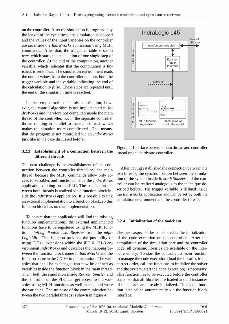
To ensure that the application will find the missingfunction implementations, the external implementedfunctions have to be registered using the MLPI func-tion mlpiLogicPouExtensionRegister from the mlpi-LogicLib. This function provides the possibility ofusing C/C++ extensions within the IEC 61131-3 en-vironmentIndraWorks and describes the mapping be-tween the function block name inIndraWorks and thefunction name in the C/C++ implementation. The vari-ables that shall be exchanged can now be defined asvariables inside the function block in the main thread.Then, both the simulation insideRexroth Simster andthe controller on the PLC can get access to the vari-ables using MLPI functions as well as read and writethe variables. The structure of the communication be-tween the two parallel threads is shown in figure 4.
IndraLogic L45
Functionblock
interface
RexrothSimster
MLPI functionregistration
Simulation ofcontroller model
Main
thre
ad
Contr
olle
r th
read
activate
input/output variables
Figure 4: Interface between main thread and controllerthread on the hardware controller
After having established the connection between thetwo threads, the synchronization between the simula-tion of the system insideRexroth Simster and the con-troller can be realized analogous to the technique de-scribed before. The trigger variable is defined insidetheIndraWorks application and can be set by both thesimulation environment and the controller thread.
3.2.4 Initialization of the toolchain
The next aspect to be considered is the initializationof the code execution on the controller. After thecompilation of the simulation core and the controllercode, all dynamic libraries are available on the inter-nal memory. To start the controller, a main functionto manage the code execution (load the libraries in thecorrect order, call the functions to initialize the solverand the system, start the code execution) is necessary.This function has to be executed before the controllerstarts, so that all libraries are loaded and all instancesof the classes are already initialized. This is the func-tion later called automatically via the function blockinterface.
A toolchain for Rapid Control Prototyping using Rexroth controllers and open source software
376 Proceedings of the 10th International ModelicaConferenceMarch 10-12, 2014, Lund, Sweden
DOI10.3384/ECP14096371
3.2.5 Resulting workflow for the toolchain
Regarding all the aspects discussed before, the result-ing workflow for the toolchain can be derived. Assum-ing, that the simulation model of the system and thecontroller inside the simulation environmentRexrothSimster already exist, the first step is to compile thesimulation core and the controller code for the oper-ating system of the controller (VxWorks). Therefore,a new project inside WindRiver Workbench has to becreated. The classes inside the simulation core have tobe compiled into dynamically linked libraries, whichleads to.out-files. These.out-files have then to bemoved to the internal flash card of the Rexroth hard-ware. This is done using an FTP client. The next stepis to register the executable main function containingthe initialization of the simulation on the controller(see section 3.2.4). The registration is done using theMLPI functionmlpiPouExtensionRegister. The syntaxis as follows:
MLPIRESULT m l p i L o g i c P o u E x t e n s i o n R e g i s t e r (c o n s t MLPIHANDLE connec t i on ,c o n s t WCHAR16∗ name ,c o n s t MLPIPOUFNCPTR f u n c t i o n ,c o n s t ULONG s i g n a t u r e = 0 ,c o n s t ULONG v e r s i o n = 0 ) .
The first input parameter is the connection handleautomatically created when a connection to the hard-ware via MLPI is established, the second parameteris the name of the POU (Program Organization Unit)in IndraWorks, in this case the name of the functionblock, the third parameter is the function pointer to theC/C++ implementation, while the fourth and fifth de-scribe the signature of the POU interface and the ver-sion of the POU library, if implemented within a li-brary, and have not necessarily to be set, as they arepredefined with 0 [7].
Now the implementation of the function block inter-face inside theIndraWorks application is made knownto the IndraWorks application. As the next step, theIndraWorks application, which only consists of thefunction block with the external implementation andthe definitions of the variables to be exchanged dur-ing the simulation as well as the trigger variable (seesection 3.2.2), can also be uploaded to the hardwaredevice (if theIndraWorks application is uploaded be-fore the registration of the functions is executed, therewill be linker errors for the external implementation ofthe function block).
The next step is to start the initialization of thecontroller on the hardware, i.e. to active the func-
tion block. Therefore the task controlling the func-tion block has to be started. This can again be realizedvia MLPI. The task is defined astriggered task, whichallows to start the task setting the activation variableto true. The start of the main function effects, thatall necessary libraries are loaded and the simulationmanager is started. Inside the simulation manager,a query is continuously performed, whether the trig-ger variable to start one calculation step is set or not.For the connection to the hardware device from theRexroth Simster side, a special component is neces-sary, which has been developed for HiL-tasks (MLPI-Coupler). The component has several inputs and out-puts and contains the MLPI-commands to both writethe data from the different inputs on the device andread the data from the device and set the values to theoutputs of the component. The names of the variablesinside IndraWorks can be set as component parame-ters.
The last step is to start the simulation insideRexrothSimster. The cycle time between the exchange of thedata can also be set in the MLPICoupler component.The simulation of the system triggers then the simu-lation on the hardware device. The synchronizationbetween both simulations is realized as described insection 3.2.2.
3.2.6 Automation of the toolchain
The toolchain presented in this work is not fully auto-mated until now. In one of the next releases ofRexrothSimster, Modelica support will be added to the sim-ulation environment. Until now, an additional Mod-elica environment is necessary to build up the con-troller simulation model. In the future, Modelica mod-els can directly be created inside the simulation tool.The code generation is integrated into the simulationcore, so that the executable code can directly be gen-erated. This allows a fully automated toolchain, wherethe controller model can be set up inside the simula-tion environment and automatically be compiled andsent to the controller. Starting the simulation insideRexroth Simster activates the toolchain (compile thecontroller model, transfer the code to the controller,load the simulation core libraries, start controller codeexecution).
4 Application on an example system
To verify the functionality, the toolchain is used to de-velop an appropriate control structure for the control
Session 2E: Modelica Tools 1
DOI10.3384/ECP14096371
Proceedings of the 10th International ModelicaConferenceMarch 10-12, 2014, Lund, Sweden
377
PressurePressure
VelocityAcceleration
cylinderstiffnesscylinder rod
Load and process
Motion controller
pressure transducer pP pressure transducer pT
HPU
WRx prop valve
cylinder port A cylinder port B
line P line T
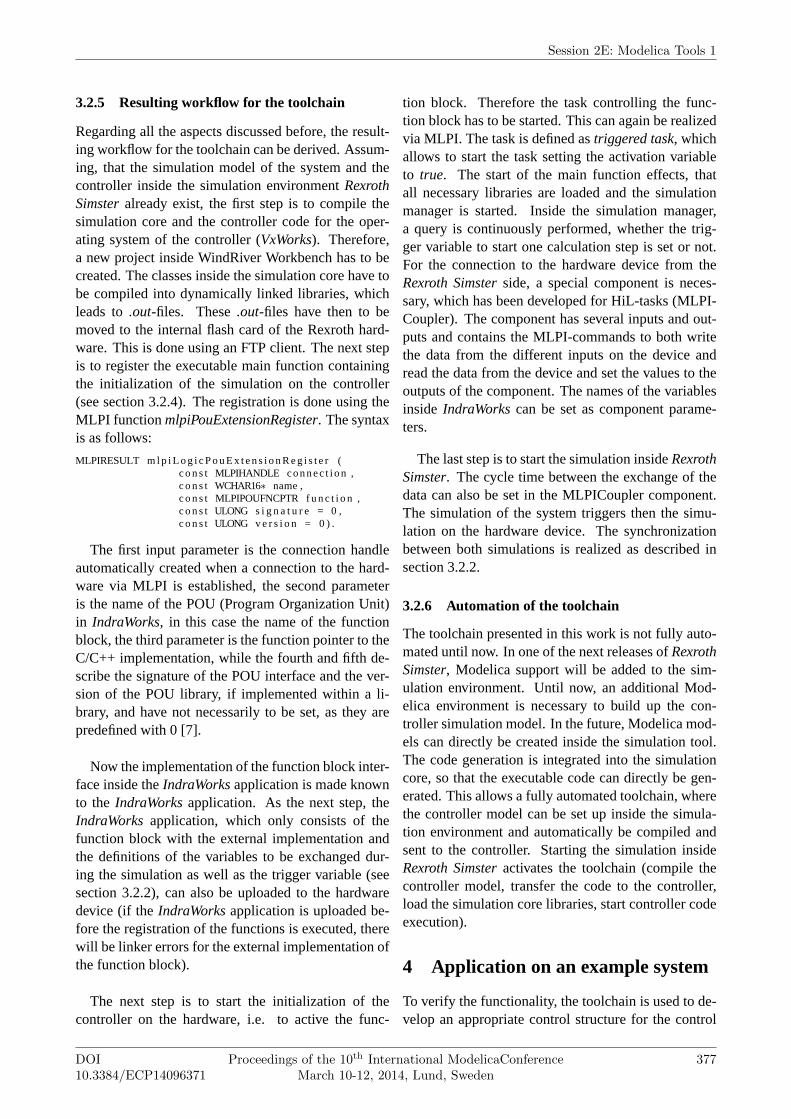
Figure 5: System model inside Rexroth Simster
of an industrial hydro-mechanical system, namely asingle hydraulic axis. This system model is build in-sideRexroth Simster and simulates the behavior of thehydro-mechanical system. The structure of this simu-lation model can be seen in figure 5. This model alsoincludes a control loop which has been developed vir-tually inside the simulation environment.
4.1 Model of the system
The single axis model consists of five sub-blocks, eachhighlighted in a different color. The light blue block isthe HPU (hydraulic pumping unit), i.e. it realizes theoil supply for the hydraulic system and includes theoil tank, a variable pump which is powered by an elec-tric motor. The motor speed is power- and pressure-controlled. Additionally an accumulator is included inthe HPU to ensure the oil supply for temporary highdemands on oil.
The yellow block shows a generic WRx propor-tional valve, which limits the volume flow of the hy-draulic fluid. Using the input signal port of the valve,the spool position of the valve can be modified. Thevalve’s dynamics is modelled with a PT2-behaviorwith power limit, the flow is modelled via a character-istic curve depending on the piston stroke (Q = f (s)).
The connections between the pump and the valve aremodelled by lines including frictional losses. The dif-ferential cylinder is modelled inside the grey box. Thesimulation model of the cylinder considers Stribeckfriction (static friction, running friction and Coulombfriction), internal leakage and external leakage. Addi-tionally the cylinder model has two end stops for thepiston, which are implemented using momentum con-servation (optionally a coefficient of restitution can bespecified).
The load is modeled inside the orange sub-box andconsiders the force resulting from the load mass, thegravity force, the plastic and the elastic deformation.The velocity of the cylinder piston is defined by theuser and is available as characteristic curve in the formv = f (t). The position profile for the cylinder, whichcan be obtained through integration of the velocityprofile, is shown in figure 6 (blue curve).
4.2 Modeling the controller
To realize the control, the current position of the cylin-der piston has to be measured. Therefore, the internalposition measuring system of the cylinder, which is in-cluded in the cylinder model, is used. As first try forthe controller structure a position controller is used.The position controller compares the current positionof the piston with the desired position from the profile.The difference (control error) is then multiplied by again factor (P-controller). The profile and the con-troller structure are implemented inside the rose boxin figure 5.
4.3 Starting the RCP process
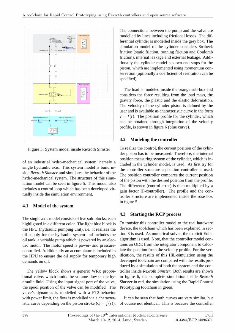
To transfer this controller model to the real hardwaredevice, the toolchain which has been explained in sec-tion 3 is used. As numerical solver, the explicit Euleralgorithm is used. Note, that the controller model con-tains an ODE from the integrator component to calcu-late the position from the velocity profile. For the ver-ification, the results of this HiL-simulation using thedeveloped toolchain are compared with the results pro-duced by a simulation of both the system and the con-troller insideRexroth Simster. Both results are shownin figure 6, the complete simulation insideRexrothSimster in red, the simulation using the Rapid ControlPrototyping toolchain in green.
It can be seen that both curves are very similar, butof course not identical. This is because the controller
A toolchain for Rapid Control Prototyping using Rexroth controllers and open source software
378 Proceedings of the 10th International ModelicaConferenceMarch 10-12, 2014, Lund, Sweden
DOI10.3384/ECP14096371
0 1 2 3 4 5 6 7−20
0
20
40
60
80
100
120
simulation time
po
sitio
n
profile curve (desired)
cylinder position RCP
cylinder position Simster
Figure 6: Results from the first controller implemen-tation and comparison with the Rexroth Simster simu-lation
insideRexroth Simster is a continuous controller andgets the position update from the cylinder in everysolver time step, while the simulation on the hardwaredevice (like every hardware controller) is updated onlyin the cycle time of the connection between simula-tion and hardware. But as the differences are verysmall, the functionality of the toolchain and the dataexchange can definitely be verified.
4.4 Improvements on the controller
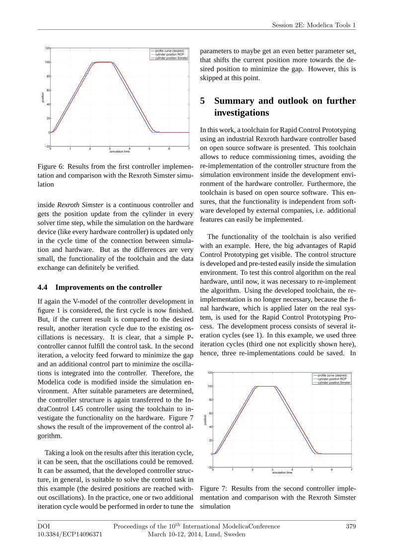
If again the V-model of the controller development infigure 1 is considered, the first cycle is now finished.But, if the current result is compared to the desiredresult, another iteration cycle due to the existing os-cillations is necessary. It is clear, that a simple P-controller cannot fulfill the control task. In the seconditeration, a velocity feed forward to minimize the gapand an additional control part to minimize the oscilla-tions is integrated into the controller. Therefore, theModelica code is modified inside the simulation en-vironment. After suitable parameters are determined,the controller structure is again transferred to the In-draControl L45 controller using the toolchain to in-vestigate the functionality on the hardware. Figure 7shows the result of the improvement of the control al-gorithm.
Taking a look on the results after this iteration cycle,it can be seen, that the oscillations could be removed.It can be assumed, that the developed controller struc-ture, in general, is suitable to solve the control task inthis example (the desired positions are reached with-out oscillations). In the practice, one or two additionaliteration cycle would be performed in order to tune the
parameters to maybe get an even better parameter set,that shifts the current position more towards the de-sired position to minimize the gap. However, this isskipped at this point.
5 Summary and outlook on furtherinvestigations
In this work, a toolchain for Rapid Control Prototypingusing an industrial Rexroth hardware controller basedon open source software is presented. This toolchainallows to reduce commissioning times, avoiding there-implementation of the controller structure from thesimulation environment inside the development envi-ronment of the hardware controller. Furthermore, thetoolchain is based on open source software. This en-sures, that the functionality is independent from soft-ware developed by external companies, i.e. additionalfeatures can easily be implemented.
The functionality of the toolchain is also verifiedwith an example. Here, the big advantages of RapidControl Prototyping get visible. The control structureis developed and pre-tested easily inside the simulationenvironment. To test this control algorithm on the realhardware, until now, it was necessary to re-implementthe algorithm. Using the developed toolchain, the re-implementation is no longer necessary, because the fi-nal hardware, which is applied later on the real sys-tem, is used for the Rapid Control Prototyping Pro-cess. The development process consists of several it-eration cycles (see 1). In this example, we used threeiteration cycles (third one not explicitly shown here),hence, three re-implementations could be saved. In
0 1 2 3 4 5 6 7−20
0
20
40
60
80
100
120
simulation time
po
sitio
n
profile curve (desired)
cylinder position RCP
cylinder position Simster
Figure 7: Results from the second controller imple-mentation and comparison with the Rexroth Simstersimulation
Session 2E: Modelica Tools 1
DOI10.3384/ECP14096371
Proceedings of the 10th International ModelicaConferenceMarch 10-12, 2014, Lund, Sweden
379
more complex systems, of course, the controller struc-ture also gets more complex.
In this contribution, the RCP toolchain is verifiedvirtually in a HiL-setup. In the future, the controllerexecuting the code has to be tested on a real system.Therefore, theIndraWorks program has to be adapted.In the HiL-setup, the simulation insideRexroth Sim-ster uses MLPI commands to write the values to thevariables in theIndraWorks application. If the con-troller is connected to a real system, the input andoutput signals are transferred via the input and outputports on the controller. Additional code for the map-ping between the I/O ports and the variables is nec-essary. An important point is the observation of thecalculation times. It has to be investigated in the fu-ture, how the strict observance of the calculation timescan be guaranteed.
Another part of the future is work is to fully auto-mate the toolchain, as described in section 3.2.6.
The simulation core can not only be used to simulatecontroller models to realize Rapid Control Prototypingand couple hardware and software in a Hardware-In-The-Loop simulation. It is also possible to simulatewhole system models, which opens the door to manyother fields of application. One field of applicationare alternative control concepts like Model PredictiveControl. Model Predictive Control calculates the cur-rent control action by solving an optimal control prob-lem at each sampling instant using the current state ofthe plant as initial state. The cost function of an opti-mal control problem is optimized subject to differentconstraints. One main constraint is the system dynam-ics in the formx = f(x, t). This condition requires thesimulation of the system in each optimization step.
References
[1] Richtlinie, V. D. I. "2206"’ - Entwick-lungsmethodik für mechatronische Systeme,Berlin 2004
[2] http://www.dspace.com/en/pub/start.cfm
[3] http://www.mathworks.com
[4] John, K.H.; Tiegelkamp, M. - IEC 61131-3: Pro-gramming Industrial Automation Systems, 2010
[5] Engels, E.; Gabler, T. - Universelle Pro-grammierschnittstelle für Motion-Logic Sys-teme - Struktur, Funktionen und Anwendung inForschung und Lehre, Tagungsband AALE 2012
[6] Worschech, N.; Mikelsons, L. - A Toolchainfor Real-Time Simulation using the OpenMod-elica Compiler. In: Proceedings of the 9th In-ternational Modelica Conference, September 3-5, 2012, Munich, Germany.
[7] Bosch Rexroth AG - Motion Logic ProgrammingInterface (MLPI) Documentation
[8] GNU GCC Release Information, URL:http://gcc.gnu.org/gcc-3.4/
A toolchain for Rapid Control Prototyping using Rexroth controllers and open source software
380 Proceedings of the 10th International ModelicaConferenceMarch 10-12, 2014, Lund, Sweden
DOI10.3384/ECP14096371