Embed Size (px)
Citation preview

A TIME-REVERSAL SPATIAL HARDENING EFFECT FOR INDOOR SPEED ESTIMATION
Feng Zhang?†, Chen Chen?†, Beibei Wang?†∗, Hung-Quoc Lai?∗ and K. J. Ray Liu?†
?Origin Wireless Inc., 7500 Greenway Center Drive, Suite 1070, MD 20770, USA.†University of Maryland, College Park, MD 20742, USA.
Email: {fzhang15, cc8834, kjrliu}@umd.edu†, {beibei.wang, quoc.lai}@originwireless.net∗
ABSTRACT
Time-reversal (TR) transmission scheme has attracted moreand more attention from both academia and industry due toits ability to focus the energy of a transmitted signal at an in-tended focal spot, both in the time and spatial domains. Basedon the extensive data collected in the real world, we observethat the energy distribution around the focal spot is highly sta-tionary and location-independent, which we call as the “TRspatial hardening effect”. This is because TR scheme addsup numerous copies of the transmitted signal bouncing offdifferent scatterers coherently and the randomness from theenvironment is averaged out. We characterize the statisticalbehaviors of the energy distribution around the focal spot us-ing a statistical model. By exploiting the hardening effect,the moving speed of transceivers can be estimated in indoorenvironments and extensive experiments show the superiorityof the proposed method compared with previous works usingRF signals.
Index Terms— indoor speed estimation, spatial harden-ing effect, time-reversal
1. INTRODUCTION
Time-reversal resonating effect is a fundamental physicalresonance phenomenon that can focus the energy of a trans-mitted signal at an intended focal spot both temporally andspatially. The research of TR dates back to the 1950s, whereTR was utilized to align the phase differences caused by mul-tipath fading during long-distance information transmissions[1], and the resonating effect was also observed in a practi-cal underwater propagation environment [2]. The capacity ofTR technology in refocusing the energy in the vicinity of anintended focal spot at a particular moment enables wide ap-plications of TR techniques in acoustic communications [3],wireless communications [1, 4, 5, 6], and indoor positioningsystems [7, 8].
TR scheme enjoys its elegant simplicity as it harvests en-ergy from the surrounding environment by exploiting the mul-tipath propagation, giving rise to the well-known TR resonat-ing effect. The TR resonating effect has been well studiedin theory under very strong assumptions on the propagation
medium such as homogeneity and discrete scattering [9, 10,11]. It is studied via numerical simulations an experimentsin controlled environments, for instance, reverberation cham-bers consisting of metallic walls [12, 13, 14]. Recently, H.El-Sallabi et al. conducted an experiment in an indoor spacewith 240 MHz bandwidth [15]. However, they investigate thespatial focusing effect at one fixed location and only with aresolution of half-wavelength, far from enough to fully unveilthe details of the energy distribution of the received signalwithin the focal spot. In addition, only a single realizationof the received energy around the focal spot was measuredwhich fails to shed light on the statistical behaviors of the en-ergy distribution.
To investigate the energy distribution within the focusingball, we collect the channel impulse responses (CIR) exten-sively in real-world rich-scattering environments with a muchfiner measurement resolution. We observe that the energydistribution inside the focusing ball is highly stationary andlocation-independent. We call such a phenomenon as the TRspatial hardening effect. Using the measurement data, we de-velop a statistical model to explain the observed TR hardeningphenomenon.
Further, this location-independent characteristic can beapplied in indoor speed estimation, since the decay of the re-ceived energy can be translated to the distance away from thefocal spot. Traditional methods for speed estimation basedon Doppler shift fails to track (human walking) speed whenRF signals are reflected by numerous scatterers in typicalindoor environments and when the speed is too slow to pro-duce perceptible Doppler shift. Other schemes such as theinertial sensor based schemes [16] and the coherence timebased method [17] cannot perform well either since they aregenerally based on the strong assumption of uniform walkingspeed. Using the location-independent characteristic of TRresonating effect, the proposed speed estimation algorithmcan produce accurate estimations in a complicated indoorenvironment using RF signals even when the speed is lowand non-uniform, which have been validated through experi-ments.
The rest of the paper is organized as follows. Section 2describes the TR transmission scheme and shows the TR res-onating effect obtained from measurement data using our own
5955978-1-5090-4117-6/17/$31.00 ©2017 IEEE ICASSP 2017

platform. TR spatial hardening effect is presented in Section 3followed by statistical explanations. Section 4 presents a TR-based indoor speed estimation algorithm and the experimentresults. Finally, conclusion is drawn in Section 5.
2. PRELIMINARIES
2.1. TR Transmission Scheme
Consider a radio rich-scattering environment, i.e., it canbe either indoor or metropolitan area. Consider a wirelesstransceiver pair each equipped with a single omnidirec-tional antenna in a rich-scattering environment. Given alarge enough bandwidth, the MPCs in a rich-scattering envi-ronment can be resolved into multiple taps in discrete-timeand let h(k; ~T → ~R0) denote the k-th tap of the CIR from~T to ~R0, where ~T and ~R0 denotes the coordinates of thetransmitter and receiver, respectively. In the TR transmissionscheme, the receiver at ~R0 first transmits an impulse and thetransmitter at ~T captures the CIR from ~R0 to ~T . Then thetransmitter at ~T simply transmits back the reversed and con-jugated version of the captured CIR, i.e., h∗(−k; ~R0 → ~T ),where ∗ denotes complex conjugation. In the following, ~R0
is called the focal spot. Without loss of generality, we useh(k; ~R) instead of h(k; ~R0 → ~T ) when ~T is fixed. With thechannel reciprocity, i.e., the forward and backward channelare identical which has been verified experimentally [8], thereceived signal at ~R can be written as
s(k; ~R) =
L−1∑l=0
h(l; ~R)h∗(l − k; ~R0), (1)
where L is the length of the CIR, h(l − k; ~R0) = 0 when(l− k) /∈ {0, 1, ..., L− 1}, and k ∈ {−(L− 1), ..., (L− 1)}.When ~R = ~R0 and k = 0, |s(k; ~R)| attains the maximumvalue
∑L−1l=0 |h(l, R)|2 when all MPCs are accumulated co-
herently, i.e., the signal energy is refocused on one particu-lar spatial location at one specific time instance. This phe-nomenon is termed as the TR spatial-temporal resonating ef-fect. To study the TR resonating effect in the spatial domain,we fix k = 0 and define the TR resonating strength (TRRS)as the normalized received signal energy at ~R, given by
η(h(~R0),h(~R)) =
∣∣∣∣∣∣∣∣∣∣s(0; ~R)√
L−1∑l=0
|h(l; ~R0)|2√L−1∑l=0
|h(l; ~R)|2
∣∣∣∣∣∣∣∣∣∣
2
,
(2)assuming the transmitter simply transmits back the time re-versed and conjugated version of ~R0.
2.2. Energy Distribution in TR Resonating Effect
To understand the TR spatial-temporal resonating effectas well as to study the spatial distribution of TRRS with a finegranularity, we conduct extensive experiments in a typical in-door environment using customized TR devices operating at5GHz ISM band with 125MHz bandwidth. The TR transmit-ter is placed at an NLOS position with no direct path betweenthe transmitter and the receiver, as shown in Fig. 1 and theTR receiver is placed on the channel probing platform. CIRscorresponding to the locations from a square area with dimen-sion 5cm × 5cm are measured and the measurement resolu-tion is 0.5cm. In total, 121 CIRs are captured. In Fig. 2, wedemonstrate the TRRS at different locations when the focalspot ~R0 is located in the middle of the square area. As wecan observe, TRRS is very close to 1 in the vicinity of ~R0, in-dicating a very high similarity in CIRs between the locationsvery close to ~R0, but decays rapidly when the distance to ~R0
increases. This observation illustrates the energy distributionof the TR spatial resonating effect around a focal spot for asingle realization.
Channel Probing Table
TR-RX TR-TX
Fig. 1. TR system prototypes and channel probing platform.
Spatial Domain
x-axis (mm)
-20 -10 0 10 20
y-a
xis
(m
m)
-20
-10
0
10
20
0
0.2
0.4
0.6
0.8
1
(a) Spatial resonating effect
Time index k (8 ns)-20 -10 0 10 20
TR
RS
0
0.2
0.4
0.6
0.8
1Time domain
(b) Temporal resonating effect
Fig. 2. TR resonating effect in spatial and time domains.
3. TR SPATIAL HARDENING EFFECT
3.1. Experiment Setup and Observations
In order to investigate the energy distribution around dif-ferent focal spots, we randomly choose 55 locations on thechannel probing platform as different focal spots. The short-est distance between any two focal spots is 20cm. For eachfocal spot ~R0, we measure the CIRs from 20 equally-spacedlocations with a resolution of 0.5cm lying on the same straight
5956
line with ~R0. For each ~R0, we calculate the TRRS betweenthe CIRs obtained at ~R0 and those associated with nearby lo-cations. Then, we plot the TRRS decay curve which depictsthe impact of distance on TRRS. In Fig. 3, we demonstratean ensemble composed by 55 TRRS decay curves as well asthe TRRS variance at different distances. The results implythat the TRRS decreases rapidly with the distance d and sat-urates when d ≥ 20mm. Meanwhile, the TRRS variance isvery small near the focal spot, indicating that the TRRS ispredictable when the distance between the focal spot and thelocation is sufficiently small. Based on this observation, we
Distance d (mm)
0 5 10 15 20 25 30 35 40
TR
resonating s
trength
0
0.2
0.4
0.6
0.8
1
(a) TRRS decays w.r.t. dDistance d (mm)
0 5 10 15 20 25 30 35 40
Variance
×10-3
0
0.5
1
1.5
2
2.5
3
3.5
4
(b) Sample variances w.r.t. d
Fig. 3. TRRS decay curves from 55 different focal spots.
define the TR spatial hardening effect as follows: in a rich-scattering environment and given a sufficiently large band-width, time-reversal can focus the energy around the focalspot in a highly predictable way.
3.2. Statistical Modeling of TR Resonating Effect
Now we treat the CIR as a random vector denoted as Hand thus h(~R) can be treated as a realization of H at loca-tion ~R. We use H(l) to denote the l-th element of H wherel = 0, 1, ..., L−1. Let (H,Hd) denote the pair of CIR randomvectors with distance d apart from each other, and a realiza-tion of (H,Hd) at location (~R0, ~R0 + ~∆) can be presented as(h(~R0),h(~R0 + ~∆)
)for any ‖~∆‖2 = d. Based on the CIR
measurements, we conclude:
Fact 1. H(l) is a complex Gaussian random variable, dis-tributed as CN(0, σ2
0e−αl), ∀l = 0, 1, ..., L− 1. 1
Fact 2. H(l) and H(k) are independent, ∀l 6= k.
We use the sample correlation ρ (H(l),Hd(k)) as themetric to quantify the correlation between H(l) and Hd(k),which is defined as
ρ (H(l),Hd(k)) =
N∑i=1
(h(i)(l)− h̄(l)
)∗ (h
(i)d (k)− h̄d(k)
)[(
N∑i=1
∣∣h(i)(l)− h̄(l)∣∣2)( N∑
i=1
∣∣∣h(i)d (l)− h̄d(l)
∣∣∣2)] 12
, (3)
1α equals to 0.1952 in our typical indoor environment.
where N is the number of samples, h(i)(l) stands for the l-thcomponent of the i-th sample pair and h̄(l) is defined as the
sample mean, i.e., h̄(l) ,N∑i=1
h(i)(l). The results in Fig. 4
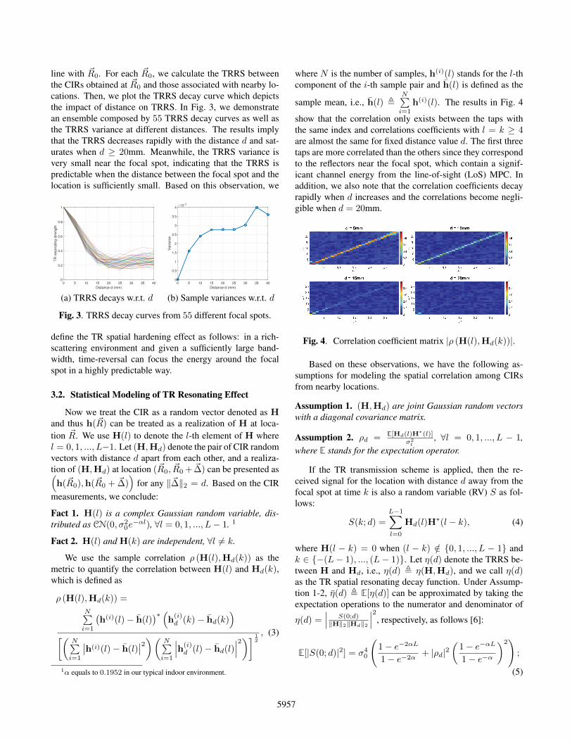
show that the correlation only exists between the taps withthe same index and correlations coefficients with l = k ≥ 4are almost the same for fixed distance value d. The first threetaps are more correlated than the others since they correspondto the reflectors near the focal spot, which contain a signif-icant channel energy from the line-of-sight (LoS) MPC. Inaddition, we also note that the correlation coefficients decayrapidly when d increases and the correlations become negli-gible when d = 20mm.
Fig. 4. Correlation coefficient matrix |ρ (H(l),Hd(k))|.
Based on these observations, we have the following as-sumptions for modeling the spatial correlation among CIRsfrom nearby locations.
Assumption 1. (H,Hd) are joint Gaussian random vectorswith a diagonal covariance matrix.
Assumption 2. ρd = E[Hd(l)H∗(l)]σ2l
, ∀l = 0, 1, ..., L − 1,where E stands for the expectation operator.
If the TR transmission scheme is applied, then the re-ceived signal for the location with distance d away from thefocal spot at time k is also a random variable (RV) S as fol-lows:
S(k; d) =
L−1∑l=0
Hd(l)H∗(l − k), (4)
where H(l − k) = 0 when (l − k) /∈ {0, 1, ..., L − 1} andk ∈ {−(L− 1), ..., (L− 1)}. Let η(d) denote the TRRS be-tween H and Hd, i.e., η(d) , η(H,Hd), and we call η(d)as the TR spatial resonating decay function. Under Assump-tion 1-2, η̄(d) , E[η(d)] can be approximated by taking theexpectation operations to the numerator and denominator of
η(d) =∣∣∣ S(0;d)‖H‖2‖Hd‖2
∣∣∣2, respectively, as follows [6]:
E[|S(0; d)|2] = σ40
(1− e−2αL
1− e−2α+ |ρd|2
(1− e−αL
1− e−α
)2)
;
(5)
5957

E[‖H‖22‖Hd‖22] = σ40
(|ρd|2
1− e−2αL
1− e−2α+
(1− e−αL
1− e−α
)2).
(6)The average of the TR spatial resonating decay function η(d)can be obtained from the measured data and the joint Gaus-sian approximations 2 respectively as shown in Fig. 5. Theresult shows that the proposed approximations match the ex-periment result well with respect to the TR spatial resonatingdecay function, which indicates that the approximations canindeed capture the essential characteristics of the TR spatialresonating effect. Given a realization of the CIR at the focal
!!"0 5 10 15 20 25
!
0
0.2
0.4
0.6
0.8
1TR Spatial Resonating Decay Functions
Measured spatial decay function
Joint Gaussian approximation
Fig. 5. The average of TR spatial resonating decay function.
spot H = h, the variance of the received signal S(0; d) is
Var[S(0; d)|H = h] = σ20(1− |ρd|2)h′Λh, (7)
where Λ is a diagonal matrix with the (k, k)-th element givenas e−α(k−1). For locations in the close vicinity of the focalspot, the variance of the received signal energy is also smallsince |ρd| is close to 1. Given a larger bandwidth, σ2
0 de-creases since the total channel power gain distributes amonga larger number of taps, which will further decrease the vari-ance of S(0; d). Therefore, the TR spatial hardening effectonly happens when the bandwidth is large enough.
4. TR-BASED SPEED ESTIMATION
The TR transceiver pair is placed in an NLOS scenarioand CIRs are measured constantly with a channel probing rateof 100Hz. The core idea of the algorithm is to translate the re-duction in the resonating strength into the moving distance ofthe TR transmitter or receiver. In addition, we use an averag-ing window with length N to further mitigate the fluctuationsof the TR spatial resonating decay function.
2The correlation coefficients are obtained from the measured CIRs.
Algorithm 1 TR indoor speed estimationInput: The most recent N CIRs: [ht−N+1, ...,ht]Output: Speed estimation at time t: v̂(t)
1: Initialization: Σ← 0, Ts (channel probing interval)2: for i ∈ {t−N + 1, ..., t− 1} do3: Σ← Σ + η(hi,hi+1)4: end for5: v̂(t) = η̄−1(Σ/(N−1))
Ts
To evaluate the performance of the speed estimationscheme, we conduct two experiments as follows. (i) In thefirst experiment, one participant carries the TR transmitterand walks at 0.5m/s. (ii) We fasten the TR transmitter to theend of a R = 2.17 meters long string and the other end of thestring is tied to the ceiling. We release the string at an angleof θ = 0.22 rads with respect to the vertical direction. Thetheoretical speed of the TR transmitter at time t can be com-puted as v(t) = θωR cos(ωt + φ), where ω =
√g/R, g is
the gravitational acceleration, and φ is the initial phase. Theexperimental results in Fig. 6 shows that the proposed speedestimation algorithm can work very well in both slow human-walking and fast-changing speed settings. One thing to noteis that the result is independent of the specific locations ofthe TR receiver even when the transceiver pair is placed in anNLOS setting which indicates that the TR spatial hardeningeffect is indeed uniform in typical indoor environments.
Time (s)
0 5 10 15 20
m/s
0
0.1
0.2
0.3
0.4
0.5
0.6
0.7
Real-time speed estimation
Controlled walking speed
Stop walking
Start walkingKeep static
(a) Walking speed estimationTime (s)
0 5 10 15 20 25
m/s
0
0.2
0.4
0.6
0.8
1
1.2Real-time speed estimation
Theoretical pendulum speed
(b) Pendulum speed estimation
Fig. 6. Experiment results of real-time speed estimations ofthe two cases.
5. CONCLUSIONS
In this paper, we present a statistical model of TRRS inclose proximity to the focal spot to depict the TR spatial hard-ening effect based on extensive experiment results in an in-door environment with fine granularity measurement. Lever-aging the TR spatial hardening effect, we present a TR-basedindoor speed estimation scheme with high accuracy in an in-door environment.
5958

6. REFERENCES
[1] C. Yan, B. Wang, Y. Han et al., “Why Time Reversal forFuture 5G Wireless?,” in IEEE Signal Processing Mag-azine, 33(2):17–26, 2016.
[2] P. Roux, B. Roman and M. Fink, “Time-reversal inan ultrasonic waveguide,” in Applied Physics Letters,70(14):1811–1813, 1997.
[3] M. Fink, “Time-reversed acoustics,” in Scientific Amer-ican, 281(5):91–97, 1999.
[4] M. Emami, M. Vu, J. Hansen, A.J. Paulraj and G. Papan-icolaou, “Matched filtering with rate back-off for lowcomplexity communications in very large delay spreadchannels,” in Proceedings of the Thirty-Eighth AsilomarConference on Signals, Systems and Computers, 218–222, 2004.
[5] B. Wang, Y. Wu, F. Han, Y. Yang and K.J. Liu, “Greenwireless communications: A time-reversal paradigm,”in IEEE Journal on Selected Areas in Communications,29(8):1698–1710, 2011.
[6] F. Han, Y. Yang, B. Wang et al., “Time-reversal di-vision multiple access over multi-path channels,” inIEEE Transactions on Communications, 60(7):1953–1965, 2012.
[7] C. Chen, Y. Chen, H.Q. Lai, Y. Han and K.J.R. Liu,“High Accuracy Indoor Localization: A WiFi-BasedApproach,” in Proceedings of IEEE International Con-ference on Acoustics, Speech and Signal Processing(ICASSP), 2016.
[8] Z.H. Wu, Y. Han et al., “A time-reversal paradigm forindoor positioning system,” in IEEE Transactions on Ve-hicular Technology, 64(4): 1331–1339, 2015.
[9] C. Oestges, A.D. Kim et al., “Characterization ofspace-time focusing in time-reversed random fields,”in IEEE Transactions on Antennas and Propagation,53(1): 283–292, 2005.
[10] J. De Rosny, G. Lerosey and M. Fink, “Theory ofelectromagnetic time-reversal mirrors,” in IEEE Trans-actions on Antennas and Propagation, 58(10): 3139–3149, 2010.
[11] L. Borcea, G. Papanicolaou, and C. Tsogka, “Theoryand applications of time reversal and interferometricimaging,” in Inverse Problems 19(6):139–164, 2003.
[12] G. Lerosey, J. De Rosny, A. Tourin and M. Fink, “Fo-cusing beyond the diffraction limit with far-field timereversal,” in Science, 315(5815): 1120–1122, 2007.
[13] G. Lerosey, J. De Rosny, A. Tourin, A. Derode andM. Fink, “Time reversal of wideband microwaves,” inApplied Physics Letters, 88(15): 154101–154101, 2006.
[14] G. Lerosey, J. De Rosny, A. Tourin, A. Derode, G. Mon-taldo, and M. Fink, “Time reversal of electromagneticwaves and telecommunication,” in Radio Science, 40(6),2005.
[15] H. El-Sallabi, P. Kyritsi, A. Paulraj, and G. Papanico-laou, “Experimental investigation on time reversal pre-coding for spacetime focusing in wireless communica-tions,” in IEEE Transactions on Instrumentation andMeasurement, 59(6): 1537–1543, 2010.
[16] Z. Yang, C. Wu, Z. Zhou, X. Zhang, X. Wang and Y. Liu,“Mobility increases localizability: A survey on wirelessindoor localization using inertial sensors,” in ACM Com-puting Surveys (CSUR), 47(3): 54, 2015.
[17] B. Pricope, and H. Haas, “Experimental validation ofa new pedestrian speed estimator for OFDM systemsin indoor environments,” in the Proceedings of IEEEGlobal Telecommunications Conference, 2011.
5959