Embed Size (px)
Citation preview

This document is downloaded from DR‑NTU (https://dr.ntu.edu.sg)Nanyang Technological University, Singapore.
A thermo‑metallurgical‑mechanical model forselective laser melting of Ti6Al4V
Li, Biao; Zhou, Kun; Tan, Pengfei; Shen, Fei
2019
Tan, P., Shen, F., Li, B., & Zhou, K. (2019). A thermo‑metallurgical‑mechanical model forselective laser melting of Ti6Al4V. Materials & Design, 168, 107642‑.doi:10.1016/j.matdes.2019.107642
https://hdl.handle.net/10356/106822
https://doi.org/10.1016/j.matdes.2019.107642
© 2019 Elsevier Ltd. This is an open access article under the CC BY‑NC‑ND license(http://creativecommons.org/licenses/by‑nc‑nd/4.0/).
Downloaded on 13 Mar 2022 13:52:59 SGT

Materials and Design 168 (2019) 107642
Contents lists available at ScienceDirect
Materials and Design
j ourna l homepage: www.e lsev ie r .com/ locate /matdes
A thermo-metallurgical-mechanical model for selective laser meltingof Ti6Al4V
Pengfei Tan, Fei Shen, Biao Li, Kun Zhou ⁎Singapore Centre for 3D Printing, School of Mechanical & Aerospace Engineering, Nanyang Technological University, 50 Nanyang Avenue, 639798, Singapore
H I G H L I G H T S G R A P H I C A L A B S T R A C T
• A thermo-metallurgical-mechanicalcoupling model for selective laser melt-ing is developed.
• The model considers powder-liquid-solid transition and solid-state phasetransformation.
• The model can predict temperature,solid-state phase and residual stressfields.
• The consideration of solid-state phasetransformation reduces tensile stressesand increases compressive stresses.
⁎ Corresponding author.E-mail address: [email protected] (K. Zhou).
https://doi.org/10.1016/j.matdes.2019.1076420264-1275/© 2019 Elsevier Ltd. This is an open access art
a b s t r a c t
a r t i c l e i n f oArticle history:Received 26 October 2018Received in revised form 21 January 2019Accepted 8 February 2019Available online 11 February 2019
A thermo-metallurgical-mechanical coupling model is developed to predict temperature, solid-state phase andresidual stress fields for the multi-track multi-layer selective laser melting process of Ti6Al4V. The model con-siders the solid-state phase transformation (SSPT) and powder-liquid-solid transition which includes melting,vaporization, solidification, shrinkage and cooling phenomena. The thermal analysis is based on the transientheat conduction problem with a volumetric heat source describing the laser absorption and scattering in thepowder bed. The volume fraction evolution of metallurgical phases is determined by temperature history andused to obtain the volumetric change strain due to the SSPT. An elasto-plastic constitutive law considering thestrains that are induced by thermal gradients and the SSPT is proposed to evaluate stress fields.Modelling resultsreveal that the consideration of the SSPT leads to the decrease of tensile residual stresses and increase of com-pressive residual stresses, and the residual stress component in the scanning direction is larger than the othertwo stress components.
icle under the CC BY-NC-ND li
© 2019 Elsevier Ltd. This is an open access article under the CC BY-NC-ND license(http://creativecommons.org/licenses/by-nc-nd/4.0/).
Keywords:3D printingSelective laser meltingThermo-metallurgical-mechanical modelResidual stress fieldSolid-state phase transformation
1. Introduction
Selective laser melting (SLM), a powder bed fusion technique, uses ahigh-intensity laser beam to selectively fuse powder particles layer bylayer for printing highly-customized and cost-effective products.
cense (
However, SLM-printed products suffer from disadvantages such aspoor surface finish, thermal distortion and unsatisfactory mechanicalstrength characteristics [1]. Among these deficiencies, residual stresses,which mainly result from large thermal gradients in the layer-wise ad-ditive manufacturing process, may have a detrimental influence on di-mensional accuracy and mechanical performance. To reduce suchinfluence, numerical approaches are widely employed to give insightinto the evolution of residual stresses as well as transient temperaturefields during the manufacturing process.
http://creativecommons.org/licenses/by-nc-nd/4.0/).

2 P. Tan et al. / Materials and Design 168 (2019) 107642
Development of a reliable thermo-mechanical coupling model isof prime significance in residual stress analysis since there exists acomplex interaction between thermal and mechanical behavioursin the SLM process. The sequentially coupling thermo-mechanicalmodel which consists of a heat transfer analysis and a subsequentstress analysis has been prevalently employed for the SLM process[2–5]. The thermo-mechanical model can provide a guide to studya variety of measures to minimize residual stresses such as processparameters optimization [6], pre-heating and post heat treatment[7–9], and scanning strategy [10–12]. In recent years, researchershave devoted efforts to improving the thermo-mechanicalmodel. Li et al. [13] developed a multi-scale methodology which in-tegrates microscale, mesoscale and macroscale thermo-mechanicalmodels. Also, Mukherjee et al. [14] improved the thermal model forresidual stress analysis by considering thermal-fluid effects in themelt pool.
Despite great progress in the current thermo-mechanical model, themetallurgical solid-state phase transformation (SSPT) has not yet beenconsidered for the stress analysis in the SLM process. The SSPT, whichis often associated with the change of material properties, volumetricchange and transformation-induced plasticity, has been recognized asa crucial factor for the formation of residual stresses for some carbonsteels and titanium alloys [15–17]. Pioneering works about the stressanalysis with consideration of the SSPT has been conducted in thelaser welding process [18–21] and direct laser deposition (DLD) process[17,22]. However, as a powder-bed manufacturing technique, SLM in-volves more complex physicochemical phenomena such as the laser-powder interaction, powder-liquid-solid transition and volume shrink-age of the powder bed. For a multi-track multi-layer SLM process, theprinted product repeatedly undergoes the SSPT due to preheating andreheating from adjacent tracks or layers, which increases the complex-ity and significance of the phase transformation. Additionally, SLM ex-hibits a high temperature gradient and rapid solidification and coolingrates, which are of great importance tomicrostructural phase formationand characteristics [23].
As a two-phase titanium alloy (α and β phases), Ti6Al4V hasattracted extensive attention for SLM owing to its high strength-to-weight ratio, excellent corrosion resistance and good stability in awide range of working temperature [6,24]. Metallurgical phase compo-sitions of Ti6Al4V in the SSPT are dependent on the temperature historyand cooling rate. The phase transformation kinetics are governed by adiffusive transformation of the α to β phase in the heating process,while the transformation product of the β phase depends on thecooling rate in the cooling process. When the cooling rate is lessthan around 20 K/s, the β phase decomposes back to the α phase[25,26]. For a faster cooling rate, the diffusionless transformationprocess from the β phase to the martensite α′ phase starts to occur.Furthermore, when the cooling rate is larger than 410 K/s, the βphase is fully transformed to the martensite phase α′ [27]. Althoughthe kinetics of the SSPT for Ti6Al4V in the SLM process have beenstudied [23,28,29], the effects of the SSPT on the thermal stress evo-lution have not been well understood.
The objective of this work is to investigate the effects of the SSPT onthe residual stress evolution during the SLM process of Ti6Al4V. Athermo-metallurgical-mechanical coupling model considering theSSPT is developed to simulate the multi-track multi-layer manufactur-ing process. The developed model considers the metallurgical SSPTand powder-liquid-solid transition including the melting, vaporization,solidification, shrinkage and cooling processes. The thermophysicaland mechanical properties associated with the temperature andmetallurgical compositions are taken into account. The temperaturefield is obtained by solving the heat conduction governing equationwith a volumetric heat source describing the laser-powder interac-tion. An elasto-plastic constitutive relationship considering the ther-mal strain and volumetric change strain is proposed to evaluatestress fields.
2. Thermo-metallurgical-mechanical coupling model development
This section introduces how to develop the thermo-metallurgical-mechanical coupling model for the SLM process. In the coupling proce-dure, the temperature field is first obtained by solving transient heatconduction and then used to evaluate the metallurgical solid-phasefield. Subsequently, the temperature and solid-state phase fields areimported into the mechanical analysis model to obtain thermal strainand volumetric change strain, respectively. A detailed coupling proce-dure is illustrated by the flowchart in Fig. A1 of Appendix A. The cou-pling model is developed by finite element method (FEM) in theANSYS parametric design language.
2.1. Thermo-metallurgical model
2.1.1. Heat conduction governing equationA three-dimensional transient heat conduction governing equation
with temperature-dependent material properties and the volumetricheat source is expressed as [30]
ρ∂H∂t
¼ ∇ � k∇ Tð Þ½ � þ QV; tN0
T ¼ T0; t ¼ 0
8<: ; ð1Þ
where T is the temperature at point (x, y, z) at time t; ρ, H and k are thetemperature-dependent density, enthalpy and thermal conductivity, re-spectively; QV is the volumetric heat source. The air natural convectionand radiation to the ambient environment on the top surface of thepowder bed can be expressed by [18].
−k∂T∂z
¼ δω T4−T∞4
� �þ hcon T−T∞ð Þ; ð2Þ
where δ is the Stefan-Boltzmann constant taken as 5.67 × 10⁸, ω is theemissivity, T∞ is the ambient temperature taken as 298 K, and hcon isthe heat convection coefficient (W/(m2·K)). Other surfaces are as-sumed to be under thermal insulating boundary conditions.
Due to the porosity in the powder bed, the laser radiation can beabsorbed or scattered by powder particles and the substrate. Based onthe interactionmodel of the laser beam and powder particles, the volu-metric heat source is expressed as [31].
QV x; y; zð Þ ¼ −γS0 x; yð Þdq ξð Þdξ
; S0 x; yð Þ ¼ 2Pπr02
e−
2 x2þy2ð Þr0
2 ; ð3Þ
where γ is the extinction coefficient, the dimensionless coordinate ξ=γz denotes the extinction thickness along the z direction, S0(x, y) is theGauss surface distribution of the laser energy, P is the laser power, r0 isthe laser beam radius and the normalized laser irradiance q is given byEqs. (B1) and (B2) in Appendix B.
2.1.2. Modelling solid-state phase transformationTi6Al4V with both α and β phases may undergo the SSPT during the
heating and cooling processes. A schematic of the volumetric changedue to the SSPT during the heating and cooling processes is given inFig. 1. When the temperature reaches the transformation temperatureBs during the heating process, the α phase starts to be transformed tothe β phase. Since the unit cell volume of the β phase is larger thanthat of the α phase, the material volume decreases with the increasingtemperature. During the cooling process, when the temperature islower than the transformation temperatureMs, thematerial volume in-creases in the phase transformation of the β to α (or α′).
During the heating process, the volume fraction of the β phase isgiven by the Castro model [32]:
f β Tð Þ ¼ 0:075þ 0:92 exp −0:0085 B f−Tð Þð Þ; 298 KbTbB f1 ; T NB f
�; ð4Þ

Fig. 1. Schematic of the volumetric change due to the SSPT.
3P. Tan et al. / Materials and Design 168 (2019) 107642
where the finish temperature Bf of the α to β phase transformation is1253 K. Due to the high cooling rate in the SLM process, the diffusivetransformation from the β phase to the α phase is suppressed and the
Fig. 2. Phase volume fractions during (a)
Fig. 3. Schematic of the SSPT in the multi-track multi-layer SLM process: (a) a layer of powdercooling down at the end of first layer; (e)–(h): a repeated process of (a)–(d) on the second lay
β phase is completely converted to the martensite α′ phase [25,33].The volume fraction of the martensite α′ phase is obtained by theKoistinen-Marburger equation [34]:
f α0 Tð Þ ¼ f0β 1− exp −0:015 Ms−Tð Þð Þð Þ; TbMs
0 ; T NMs
�ð5Þ
where fβ′ is the initial volume fraction of the β phase in the martensitetransformation and the transformation temperature Ms is taken to be923 K in this model. The phase volume fractions during heating andcooling processes are plotted in Fig. 2).
A schematic of the SSPT in themulti-trackmulti-layer SLMprocess isshown in Fig. 3. A layer of powder particles is initially spread on the sub-strate (see Fig. 3(a)). The main phase composition of the powder andsubstrate is the α phase. In (b), when the first track is scanned by thelaser beam, the heat affected zone of the powder layer and substratewith a temperature of over 1253 K is transformed to the β phase. Dueto the preheating from the first track, some powder particles in the sec-ond track are also transformed to the β phase.When the second track isscanned, the two-track powder layer and one part of the substrate be-comes the β phase as given in (c). After a short cooling time at theend of the first layer, the martensite phase transformation occurs inthe zone with a temperature lower than 923 K as given in (d). A re-peated process of (a)–(d) on the second layer is given in (e)–(h). It is
heating and (b) cooling processes.
particles is spread; (b) the first track is scanned; (c) the second track is scanned; (d) afterer.

4 P. Tan et al. / Materials and Design 168 (2019) 107642
observed from (f) and (g) that a portion of the zonewith themartensiteα′ phase is transformed to the β phase due to reheating from the secondlayer. After cooling down to the ambient temperature, the printed partbecomes martensite α′ phase, as illustrated in (h).
2.2. Mechanical model
In the mechanical model, temperature and solid-state phasefields obtained from the previous thermo-metallurgical model areused as input parameters to evaluate the thermal strain and volu-metric change strain, respectively. The total strain increment dεTotalis expressed by
dεTotal ¼ dεe þ dεp þ dεth þ dεtr; ð6Þ
where dεe is the elastic strain increment, dεp is the plastic strain in-crement, dεth is the thermal strain increment and dεtr is the volumet-ric change strain increment due to the SSPT.
The plastic strain increment is given by considering theflowplasticity:
dεp ¼ dλ∂ f∂σ
� �; ð7Þ
where λ is the hardening parameter, σ is the stress tensor and the yieldfunction f is obtained by the von Mises yield criterion:
f ¼ σvon−σyield; ð8Þ
where σyield and σvon are the yield stress and von Mises stress, respec-tively. The thermal strain increment is expressed as
dεth ¼ αTΔT ; ð9Þ
where αT is the coefficient of thermal expansion.The volumetric change strain increment is given by [26].
dεtr ¼ εΔV Tð ÞΔ f i Tð Þ; ð10Þ
where εΔV is the volumetric change strainwith a full SSPT and fi(T) is thephase volume fraction. The volumetric change strain εΔV can be deter-mined by the lattice parameter of crystal structures for α and β phases[26,35,36]:
εΔV ¼ffiffiffiffiffiffiVβ
3p
−ffiffiffiffiffiffiVα
3p
ffiffiffiffiffiffiVα
3p ; ð11Þ
Fig. 4. (a) Unit cell volumes for α and β phases and (b
where Vα and Vβ are unit cell volumes of α and β phases, respectively.The unit cell volumes of α and β phases and the volume change strainεΔV are plotted in Fig. 4.
The volumetric change strain is obtained for the heating and coolingprocesses by substituting the volume fractions given in Eqs. (4) and (5)to Eq. (10):
dεtr ¼ αhΔT; HeatingαcΔT; Cooling
�; ð12Þ
where
αh ¼ −0:00782 exp −0:0085 1253−Tð Þ½ �εΔVh Tð Þ; 473→1253 Kαc ¼ −0:015 exp −0:015 923−Tð Þ½ �εΔVc Tð ÞT ; 473←923 K
�ð13Þ
Since both the thermal strain and volumetric change strain are afunction of the temperature gradient ΔT, they can be combined:
dεth þ dεtr ¼ αh þ αTð ÞΔT; Heatingαc þ αTð ÞΔT; Cooling
�ð14Þ
Hence, the SSPT is considered in themechanical analysis by incor-porating the volumetric change strain into the thermal strain in theFEM model.
2.3. Volume shrinkage of the powder bed
The volume of the powder bed is decreased after the powder par-ticles are melted by the laser beam. The volume decrease resultsfrom the volume shrinkage of the porous powder layer and vaporiza-tion. The vaporized metal can be neglected compared with the vol-ume shrinkage. Hence, the volume shrinkage is 40% of the powderbed volume because the porosity of the powder bed is assumed tobe 0.4 [37]. A detailed multi-step algorithm for the multi-trackmulti-layer SLM process considering the volume shrinkage isdiscussed in our previous work [5]. The volume decrease is simulatedby activating and deactivating elements by the element birth anddeath technique in ANSYS software. After the volume of the powderbed is reduced, the top surface of the printed part is assumed to beflat. The thermophysical properties of the materials including thedensity, heat conductivity and enthalpy are associated with the vol-ume shrinkage. The material properties are changed from powderparticles to the bulk material as the temperature is over the meltingpoint. Since the powder particles have no mechanical effect on the
) volumetric change strain with a full SSPT [26].

5P. Tan et al. / Materials and Design 168 (2019) 107642
printed part, the elements of fresh powder particles are deactivatedin the mechanical analysis.
2.4. Material properties
The thermophysical properties used in the coupling model includethermal conductivity, density and enthalpy for powder particles andbulk material. The density ρp is a function of the powder porosity:
ρp ¼ 1−φð Þρb; TbTmρb; T NTm
�; ð15Þ
where the porosityφ is 0.4 [37], themelting point Tm is 1923 K and ρb isthe density of the bulkmaterial. The effective thermal conductivity kp ofthe powder bed is estimated as [38].
kpka
¼ 1−ffiffiffiffiffiffiffiffiffiffiffi1−φ
p� �1þ φkr
ka
� �
þffiffiffiffiffiffiffiffiffiffiffi1−φ
p 21−ka=kb
kbka
ln kb=kað Þ−1� �
þ krka
; ð16Þ
where ka is the thermal conductivity of air, kb is the thermal conductiv-ity of the bulkmaterial and kr is the thermal conductivity portion due toradiation among powder particles:
kr ¼ 4FδT3dr; ð17Þ
where δ is the Stefan-Boltzmann constant, dr is the average diameter ofpowder particles and F is the view factor which is taken as 1/3. To con-sider melting and vaporization processes, the latent heat is directlyadded to the enthalpy. The latent heat is taken as 286 kJ/kg for meltingand 9830 kJ/kg for vaporization [16,26,39]. The temperature-dependent
Fig. 5. Thermophysical properties of the Ti6Al4V bulk and powder par
thermophysical properties of the Ti6Al4V powder particles and bulkmaterial are depicted in Fig. 5.
The temperature-dependent mechanical properties of Ti6Al4V, in-cluding the Young's modulus E, Poisson ratio υ, the coefficient of ther-mal expansion (CTE) αT, yield stress σyield and tangent modulus ET, areplotted in Fig. 6. The tangent modulus is assumed to be about 1/20 ofthe Young's modulus [38]. A bilinear stress-strain constitutive relationis used for the plastic deformation as shown in Fig. 7, which requiresthe initial yield stress σyield and tangent modulus ET as inputparameters.
3. Results and discussion
In this section, the temperature, solid-state phase and residual stressfields are analyzed and the effects of the SSPT on residual stresses are in-vestigated based on the thermo-metallurgical-mechanical couplingmodel.
3.1. Temperature field
The thermalmodel is validated by comparing thewidth and depth ofthe simulated melt pool with experimental results. The liquid-solidphase distributions in the x-z cross section of the powder layer and sub-strate with various powers from 20 to 80 W are shown in Fig. 8. Thesolid and liquid phases are represented by blue and red colors, respec-tively. By considering the volume shrinkage of the powder bed, thewidth and depth of the melt pool is calculated by
Width ¼ w
Depth ¼ d−d� φ;d≤hd−h� φ; dNh
�8<: ; ð18Þ
ticles: (a) density, (b) heat conductivity and (c) enthalpy [40,41].

Fig. 6.Mechanical properties for Ti6Al4V: (a) Young's modulus, (b) coefficient of thermal expansion, (c) Poisson ratio and (d) yield stress [3,4].
6 P. Tan et al. / Materials and Design 168 (2019) 107642
wherew is thewidth of themelt pool, d is the depth of themolten pow-der bed and substrate, h is the depth of themolten powder bed and φ isthe powder porosity. The simulation has been carried out with a scan-ning velocity of 200 mm/s and a laser beam radius of 26 μm. The com-parison between modelled melt pool sizes and experimental results[42] is illustrated in Fig. 9. From the comparison, the depth and widthof the melt pool predicted by the model shows good agreement withthe experimental results.
The mesh of the FEM model and scanning pattern for a multi-layerSLM process are shown in Fig. 10. A fine mesh is used for the four-layer printed part and the heat affected zone of the substrate. A unidi-rectional scanning pattern is adoptedwithin one layer and the scanningdirections between two layers are orthogonal. The material of both the
Fig. 7. A bilinear temperature-dependent constitutive relationship for Ti6Al4V [3,4].
substrate and powder layer is Ti6Al4V. A modelling scheme for themulti-layer SLM process considering the volumetric decrease due tovolume shrinkage of the powder bed is reported in our previous paper[5]. Themodelling process parameters are listed in Table 1. The temper-ature evolution for a four-layer printing process is given in Fig. 11. Aftereach layer isfinished, the cooling time is 0.1 s. The scanned region by thelaser beam becomes thinner due to the consideration of volume shrink-age. Heat diffusion from the heated region to the surrounding freshpowder particles is slow because heat conductivity is low in the powderbed.
3.2. Solid-state phase field
The temperature and β phase fields in the x-z and y-z cross sectionsfor a one-track printingprocess are demonstrated in Fig. 12. The powderbed consists of 92.5% α phase and 7.5% β phase at initial condition ac-cording to the Castro model in Eq. (4). The α phase starts to becomethe β phase with increasing temperature. As the temperature is higherthan Bf = 1253 K, the α phase is fully transformed to the β phase. Thematerial above around −40 μm in the z direction is completelytranformed to the β phase around the scanned region by the laserbeam. The volume fraction of the β phase gradually decreases in the re-gion further away from the heat affected zone.
The evolution of the solid-state phasefields for a three-track printingprocess is shown in Fig. 13. In thefirst track as shown in (a), thematerialwith the temperature of over 1253 K is fully transformed to the β phaseand the region with lower temperature is a combination of α and βphases. The martensite α′ phase does not occur at this moment. Whenthe second track is being scanned, the first-track regionmainly containsthe β phase because the temperature in this region is still higher thanthe martensitic transformation temperature (923 K). Only a small re-gion around the edge of the heat affected zone in the substrate un-dergoes the martensitic transformation. When the third track is beingscanned, the region with the β phase increases and more α′ phase oc-curs at the bottom of the first-track heated region. After cooling down,
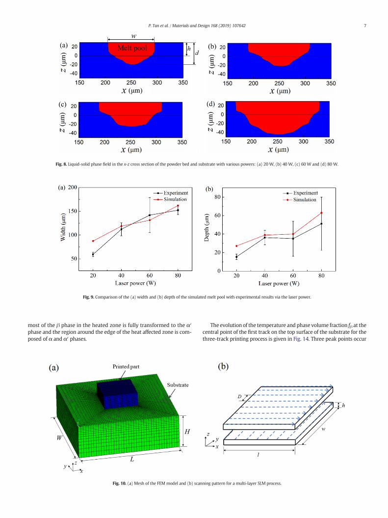
Fig. 9. Comparison of the (a) width and (b) depth of the simulated melt pool with experimental results via the laser power.
Fig. 8. Liquid-solid phase field in the x-z cross section of the powder bed and substrate with various powers: (a) 20 W, (b) 40 W, (c) 60 W and (d) 80 W.
7P. Tan et al. / Materials and Design 168 (2019) 107642
most of the β phase in the heated zone is fully transformed to the α′phase and the region around the edge of the heat affected zone is com-posed of α and α′ phases.
Fig. 10. (a) Mesh of the FEM model and (b) scan
The evolution of the temperature and phase volume fraction fβ at thecentral point of the first track on the top surface of the substrate for thethree-track printing process is given in Fig. 14. Three peak points occur
ning pattern for a multi-layer SLM process.

Table 1Modelling process parameters for a multi-layer SLM process.
Parameters Value
Layer thickness h (μm) 50Laser beam radius r0 (μm) 60Laser power P (W) 100Laser scan speed v (mm/s) 600Ambient temperature T∞ (K) 298Hatch distance D (μm) 72Substrate L × W × H (mm3) 1.5 × 1.5 × 0.5Powder layer l × w × h (mm3) 0.5 × 0.5 × 0.05
8 P. Tan et al. / Materials and Design 168 (2019) 107642
in the temperature history because the point is heated three timeswhilethree tracks are scanned by the laser beam sequentially. The peak tem-perature decreases because the laser beam is gradually moving awayfrom thepoint.When the laser beam reaches the point, the temperaturedramatically increases to 2480 K and the α phase completely becomes
Fig. 11. Evolution of the temperature fields for a four-layer SLM process: (a) at the end of the firend of the fourth layer.
Fig. 12. (a) Temperature and (b) β phase fields in the x-z a
the β phase at the same time. Then, the point remains in the β phaseuntil the three tracks are scanned. After the scanning is finished, thetemperature at the point gradually decreases to the martensitic trans-formation temperature Ms. The β phase can be fully transformed tothe martensite α′ phase due to the fast cooling rate.
3.3. Residual stress field
In this case, the stress fields for a one-layer printing process are firstinvestigated. The unidirectional scanning strategywith a hatch distanceD = 1.2r0 is used. The printing process parameters including laser pa-rameters and the powder layer thickness are the same as those listedin Table 1 for themulti-layer printing process. In addition, the substrateplate is fixed for the mechanical analysis:
w ¼ 0; at z ¼ −Hu ¼ 0; at x ¼ 0 and Wv ¼ 0; at y ¼ 0 and L
8<: ; ð19Þ
st track, (b) at the end of the first layer, (c) at themiddle time of the third layer and at the
nd y-z cross sections for a one-track printing process.

Fig. 13. Solid-state phase fields for a three-track printing process in the x-z cross section at the different time: (a) first track, (b) second track, (c) third track and (d) after cooling down.
9P. Tan et al. / Materials and Design 168 (2019) 107642
where u, v and w are the displacements in the x, y and z directions, re-spectively;W, L and H are the length, width and height of the substrateplate, respectively.
Fig. 15 illustrates the comparison of von Mises stress fields withoutand with the SSPT for the one-layer printing process at different in-stances of time. The printing time tm of the one-layer eight-track print-ing process is 6.67 × 10⁻³ s. The printed part approaches the ambient
Fig. 14. Evolution of the (a) temperature and (b) phase volume fraction fβ for a three-trackprinting process.
temperature T∞ = 298 K after 500 s of cooling. Fig. 15(a) gives the vonMises stress fields when one half of the powder bed is scanned by thelaser beam. The grey part represents deactivated fresh powder particleswhich have no influence on the mechanical analysis of the printed part.The blue region has a low stress level because this region is the meltpool where the Young's modulus and yield stress are assumed to bevery small. A large stress occurs at the first-track region at the end ofthe laser scanning process as shown in Fig. 15(b), which is caused bythe formation of tensile residual stresses after the laser beam movesaway. The vonMises stress increases as the temperature declines duringthe cooling process, as given in Fig. 15(c) and (d). The large stress is dis-tributed along the scanning track because these regions suffer fromhightemperature gradients, which is consistent with the reported results in[10,43].
Fig. 15 also shows that the stress level with the SSPT is smallerthan that without the SSPT during laser scanning and cooling pro-cesses. This can be explained by the volume change schematic dueto the SSPT as shown in Fig. 1. The material volume decreasesduring the heating process and increases during the cooling process,which is different from the thermal expansion and contractioncaused by the temperature change. As a result, the SSPT and thermalgradients have an opposite effect on the evolution of the thermalstress field.
Residual stress components with and without the SSPT forthe one-layer printed part are demonstrated in Fig. 16. Comparedwith the other two stress components σx and σz, the stresscomponent σy has the maximum stress because the scanning
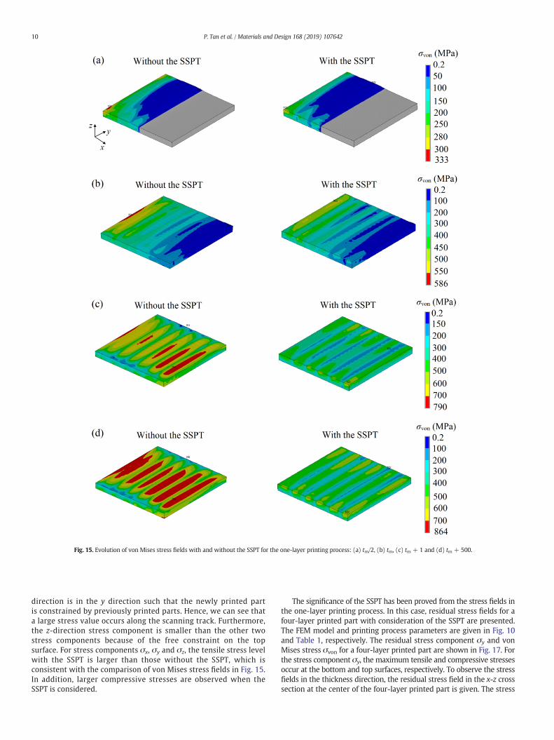
Fig. 15. Evolution of von Mises stress fields with and without the SSPT for the one-layer printing process: (a) tm/2, (b) tm, (c) tm + 1 and (d) tm + 500.
10 P. Tan et al. / Materials and Design 168 (2019) 107642
direction is in the y direction such that the newly printed partis constrained by previously printed parts. Hence, we can see thata large stress value occurs along the scanning track. Furthermore,the z-direction stress component is smaller than the other twostress components because of the free constraint on the topsurface. For stress components σx, σy and σz, the tensile stress levelwith the SSPT is larger than those without the SSPT, which isconsistent with the comparison of von Mises stress fields in Fig. 15.In addition, larger compressive stresses are observed when theSSPT is considered.
The significance of the SSPT has been proved from the stress fields inthe one-layer printing process. In this case, residual stress fields for afour-layer printed part with consideration of the SSPT are presented.The FEM model and printing process parameters are given in Fig. 10and Table 1, respectively. The residual stress component σy and vonMises stress σvon for a four-layer printed part are shown in Fig. 17. Forthe stress component σy, the maximum tensile and compressive stressesoccur at the bottom and top surfaces, respectively. To observe the stressfields in the thickness direction, the residual stress field in the x-z crosssection at the center of the four-layer printed part is given. The stress

Fig. 16. Residual stress fields with and without the SSPT for the one-layer printed part: (a) σx, (b) σy and (c) σz.
11P. Tan et al. / Materials and Design 168 (2019) 107642
components σy has tensile stress in the first three layers and compressivestress at the fourth-layer region. Fig. 17(b) shows that themaximum vonMises stress is at the bottom just like the stress component σy and theminimum stress is at the middle region, which is also observed in otherreported simulation results [7,8]. In addition, the maximum stress in thefour-layer printed part (871 MPa) is larger than the maximum vonMises stress of the one-layer part (606 MPa).
4. Conclusions
Despite great advances in the thermo-mechanical modelling of theSLM process, a comprehensive understanding of thermal and mechani-cal behaviourswith consideration of the phase transformation phenom-ena is rarely reported. Hence, this work investigates the thermo-metallurgical-mechanical behaviours of the Ti6Al4V productmanufactured by SLM technique. The sequentially coupling modelwhich consists of thermal, metallurgical and mechanical analyses aimsat predicting the temperature, solid-phase and stress fields during theSLM process. The effects of the repeated SSPT on residual stress fieldsin themulti-trackmulti-layer process has been studied based on the de-veloped model. The modelling results show that consideration of theSSPT gives rise to the decrease of tensile residual stresses and the in-crease of compressive residual stresses. For a one-layer printed part,
the stress component in the scanning direction is larger than the othertwo stress components. In a four-layer printed part, the maximumvon Mises stress is located at the bottom region.
The thermo-metallurgical-mechanical coupling model is a usefultool in process parameter optimization for improving dimensional accu-racy andmechanical performance of SLM-printed products. Besides, themulti-track multi-layer model can also be extended to predict residualstresses of complex practical components fabricated by the laser addi-tive manufacturing process.
Author contributions
P. Tan developed themodel, conducted simulation and analysis, andwrote the manuscript. K. Zhou initiated the idea, analyzed the resultsandworked on themanuscript. F. Shen analyzed the results andworkedon the manuscript. B. Li analyzed the results and worked on themanuscript.
Acknowledgements
The authors would like to acknowledge the financial support fromthe National Research Foundation Medium Sized Center, Singaporethrough the Marine and Offshore Program.

Fig. 17. Residual stress fields for a four-layer printed part with the SSPT: (a) σy and (b) σvon.
12 P. Tan et al. / Materials and Design 168 (2019) 107642
Appendix A. Flowchart for a thermo-metallurgical-mechanical coupling model for the SLM process
Fig. A1. Flowchart of a thermo-metallurgical-mechanical coupling model for the SLM process.

13P. Tan et al. / Materials and Design 168 (2019) 107642
A flowchart to describe the coupling model for analyzing residualstresses in the SLM process is illustrated in Fig. A1. The heat absorbedfrom the laser beam diffuses through heat conduction in the powderbed and substrate, heat convection in the melt pool, and air convectionand radiation with the ambient environment. The thermal model isbased on the heat conduction governing equation because heat conduc-tion occupies a main role in the instantaneous diffusion of heat. The airconvection and radiation are considered as boundary conditions. A vol-umetric heat source is used to represent the interaction between thelaser beam and powder particles due to the porosity of the powderbed. The volume fractions of solid-state phases during the heating andcooling processes are predicted by semi-empirical formulas which area function of the temperature. The temperature and solid-state phasefields are imported into the mechanical analysis model to obtain thethermal strain and volumetric change strain, respectively. Finally, anelasto-plastic constitutive relationship considering the thermal strainand volumetric change strain is proposed to evaluate stress fields.
Appendix B. Normalized laser irradiance q for the volumetric heatsource
By solving the radiation transfer equation in the thickness directionof the powder bed, the normalized laser irradiance q is given as [31]:
q ξð Þ ¼ ηa4η−3ð ÞD 1−η2
� �e−λ 1−að Þe−2aξ þ 1þ að Þe2aξ
h i− 3þ ηe−2λ� �
� 1þ a−η 1−að Þ½ �e2a λ−ξð Þ þ 1−a−η 1þ að Þ½ �e2a λ−ξð Þ
−3 1−ηð Þ e−ξ−ηeξ−2λ
� �4η−3
ðB1Þ
D ¼ 1−að Þ 1−a−η 1þ að Þ½ �e−2aλ− 1þ að Þ 1þ a−η 1−að Þ½ �e2aλ; ðB2Þ
where η is the hemispherical reflectivity of powder particles, a=ffiffiffiffiffiffiffiffiffiffi1−η
p,
and the optical thickness λ= γLwith L being the thickness of the powderlayer.
References
[1] T. DebRoy, H.L. Wei, J.S. Zuback, T. Mukherjee, J.W. Elmer, J.O. Milewski, A.M. Beese,A. Wilson-Heid, A. De, W. Zhang, Additive manufacturing of metallic components –process, structure and properties, Prog. Mater. Sci. 92 (2018) 112–224.
[2] P. Mercelis, J.P. Kruth, Residual stresses in selective laser sintering and selective lasermelting, Rapid Prototyp. J. 12 (5) (2006) 254–265.
[3] N.E. Hodge, R.M. Ferencz, J.M. Solberg, Implementation of a thermomechanicalmodel for the simulation of selective laser melting, Comput. Mech. 54 (1) (2014)33–51.
[4] I. Yadroitsev, I. Yadroitsava, Evaluation of residual stress in stainless steel 316L andTi6Al4V samples produced by selective laser melting, Virtual Phys. Prototyp. 10 (2)(2015) 67–76.
[5] Y. Li, K. Zhou, P. Tan, S.B. Tor, C.K. Chua, K.F. Leong, Modeling temperature and resid-ual stress fields in selective laser melting, Int. J. Mech. Sci. 136 (2018) 24–35.
[6] H. Shipley, D. McDonnell, M. Culleton, R. Coull, R. Lupoi, G. O'Donnell, D. Trimble,Optimisation of process parameters to address fundamental challenges during se-lective laser melting of Ti-6Al-4V: a review, Int. J. Mach. Tools Manuf. 128 (2018)1–20.
[7] X. Lu, X. Lin, M. Chiumenti, M. Cervera, J. Li, L. Ma, L. Wei, Y. Hu, W. Huang, Finite el-ement analysis and experimental validation of the thermomechanical behavior inlaser solid forming of Ti-6Al-4V, Addit. Manuf. 21 (2018) 30–40.
[8] J. Cao, M.A. Gharghouri, P. Nash, Finite-element analysis and experimental valida-tion of thermal residual stress and distortion in electron beam additivemanufactured Ti-6Al-4V build plates, J. Mater. Process. Technol. 237 (2016)409–419.
[9] T. Furumoto, T. Ueda, A. Aziz, M. Sanusi, A. Hosokawa, R. Tanaka, Study on reductionof residual stress induced during rapid tooling process: influence of heating condi-tions on residual stress, Key Eng. Mater. (2010) 785–789.
[10] L. Parry, I. Ashcroft, R.D. Wildman, Understanding the effect of laser scan strategy onresidual stress in selective laser melting through thermo-mechanical simulation,Addit. Manuf. 12 (2016) 1–15.
[11] M.F. Zaeh, G. Branner, Investigations on residual stresses and deformations in selec-tive laser melting, Prod. Eng. 4 (1) (2009) 35–45.
[12] H. Ali, H. Ghadbeigi, K. Mumtaz, Effect of scanning strategies on residual stress andmechanical properties of selective laser melted Ti6Al4V, Mater. Sci. Eng. A 712(2018) 175–187.
[13] C. Li, C.H. Fu, Y.B. Guo, F.Z. Fang, A multiscale modeling approach for fast predictionof part distortion in selective laser melting, J. Mater. Process. Technol. 229 (2016)703–712.
[14] T. Mukherjee, W. Zhang, T. DebRoy, An improved prediction of residual stresses anddistortion in additive manufacturing, Comput. Mater. Sci. 126 (2017) 360–372.
[15] L. Costa, R. Vilar, T. Reti, A.M. Deus, Rapid tooling by laser powder deposition: pro-cess simulation using finite element analysis, Acta Mater. 53 (14) (2005)3987–3999.
[16] J.W. Elmer, T.A. Palmer, S.S. Babu, W. Zhang, T. DebRoy, Phase transformation dy-namics during welding of Ti–6Al–4V, J. Appl. Phys. 95 (12) (2004) 8327–8339.
[17] Y. Fan, P. Cheng, Y.L. Yao, Z. Yang, K. Egland, Effect of phase transformations on laserforming of Ti–6Al–4V alloy, J. Appl. Phys. 98 (1) (2005), 013518. .
[18] C.-H. Lee, K.-H. Chang, Finite element simulation of the residual stresses in highstrength carbon steel butt weld incorporating solid-state phase transformation,Comput. Mater. Sci. 46 (4) (2009) 1014–1022.
[19] M. Zain-ul-abdein, D. Nélias, J.-F. Jullien, F. Boitout, L. Dischert, X. Noe, Finite elementanalysis of metallurgical phase transformations in AA 6056-T4 and their effectsupon the residual stress and distortion states of a laser welded T-joint, Int. J. Press.Vessel. Pip. 88 (1) (2011) 45–56.
[20] M.R. Allazadeh, C.I. Garcia, FEM technique to study residual stresses developed incontinuously cast steel during solid–solid phase transformation, Ironmak. Steelmak.38 (8) (2013) 566–576.
[21] D. Deng, FEM prediction of welding residual stress and distortion in carbon steelconsidering phase transformation effects, Mater. Des. 30 (2) (2009) 359–366.
[22] A. Suárez, M.J. Tobar, A. Yáñez, I. Pérez, J. Sampedro, V. Amigó, J.J. Candel, Modelingof phase transformations of Ti6Al4V during laser metal deposition, Phys. Procedia 12(2011) 666–673.
[23] J. Yang, H. Yu, J. Yin, M. Gao, Z. Wang, X. Zeng, Formation and control of martensitein Ti-6Al-4V alloy produced by selective laser melting, Mater. Des. 108 (2016)308–318.
[24] H. Ali, H. Ghadbeigi, K. Mumtaz, Residual stress development in selective laser-melted Ti6Al4V: a parametric thermal modelling approach, Int. J. Adv. Manuf.Technol. 97 (5–8) (2018) 2621–2633.
[25] R. Filip, K. Kubiak, W. Ziaja, J. Sieniawski, The effect of microstructure on the me-chanical properties of two-phase titanium alloys, J. Mater. Process. Technol. 133(1–2) (2003) 84–89.
[26] J. Ahn, E. He, L. Chen, R.C. Wimpory, J.P. Dear, C.M. Davies, Prediction and measure-ment of residual stresses and distortions in fibre laser welded Ti-6Al-4V consideringphase transformation, Mater. Des. 115 (2017) 441–457.
[27] T. Ahmed, H. Rack, Phase transformations during cooling in α+ β titanium alloys,Mater. Sci. Eng. A 243 (1–2) (1998) 206–211.
[28] W. Xu, M. Brandt, S. Sun, J. Elambasseril, Q. Liu, K. Latham, K. Xia, M. Qian, Additivemanufacturing of strong and ductile Ti–6Al–4V by selective laser melting via in situmartensite decomposition, Acta Mater. 85 (2015) 74–84.
[29] S. Lu, M. Qian, H. Tang, M. Yan, J.Wang, D. StJohn, Massive transformation in Ti–6Al–4V additively manufactured by selective electron beam melting, Acta Mater. 104(2016) 303–311.
[30] H. Carslaw, J. Jaeger, Conduction of Heat in Solids, Oxford Science Publications, Ox-ford, England, 1959.
[31] A.V. Gusarov, I. Yadroitsev, P. Bertrand, I. Smurov, Model of radiation and heat trans-fer in laser-powder interaction zone at selective lasermelting, J. Heat Transf. 131 (7)(2009), 072101. .
[32] M. Avrami, Kinetics of phase change. II transformation-time relations for randomdistribution of nuclei, J. Chem. Phys. 8 (2) (1940) 212–224.
[33] G. Krauss, Deformation and fracture in martensitic carbon steels tempered at lowtemperatures, Metall. Mater. Trans. A 32 (4) (2001) 861–877.
[34] D. Koıstinen, R. Marbürger, A general equation prescribing extent of austenite-martensite transformation in pure Fe-C alloy and plain carbon steels, Acta Metall.7 (1) (1959) 59–60.
[35] S.H. Cho, J.W. Kim, Analysis of residual stress in carbon steel weldment incorporat-ing phase transformations, Sci. Technol. Weld. Join. 7 (4) (2013) 212–216.
[36] J.W. Elmer, T.A. Palmer, S.S. Babu, E.D. Specht, In situ observations of lattice expan-sion and transformation rates of α and β phases in Ti–6Al–4V, Mater. Sci. Eng. A391 (1–2) (2005) 104–113.
[37] A. Hussein, L. Hao, C. Yan, R. Everson, Finite element simulation of the temperatureand stress fields in single layers built without-support in selective laser melting,Mater. Des. 52 (2013) 638–647.
[38] K. Dai, L. Shaw, Thermal and mechanical finite element modeling of laser formingfrom metal and ceramic powders, Acta Mater. 52 (1) (2004) 69–80.
[39] R. Rai, J.W. Elmer, T.A. Palmer, T. DebRoy, Heat transfer and fluid flow during key-hole mode laser welding of tantalum, Ti–6Al–4V, 304L stainless steel and vanadium,J. Phys. D. Appl. Phys. 40 (18) (2007) 5753–5766.
[40] K.C. Mills, Recommended Values of Thermophysical Properties for Selected Com-mercial Alloys, Woodhead Publishing Ltd, 2002.
[41] V. Bobkov, L. Fokin, E. Petrov, V. Popov, V. Rumiantsev, A. Savvatimsky,Thermophysical Properties of Materials for Nuclear Engineering: A Tutorial and Col-lection of Data, IAEA, Vienna, 2008.
[42] F. Verhaeghe, T. Craeghs, J. Heulens, L. Pandelaers, A pragmatic model for selectivelaser melting with evaporation, Acta Mater. 57 (20) (2009) 6006–6012.
[43] S. Tadano, T. Hino, Y. Nakatani, A modeling study of stress and strain formation in-duced during melting process in powder-bed electron beammelting for Ni superal-loy, J. Mater. Process. Technol. 257 (2018) 163–169.