Embed Size (px)
Citation preview

A Theoretical, Computational, and Experimental Analysis of anInterdigital Armature in a High Velocity Railgun
Robert MacGregor and Sikhanda SatapathyAugust, 2002
Institute for Advanced TechnologyThe University of Texas at Austin3925 W. Braker Lane, Suite 400
Austin, TX 78759
Abstract
One of the challenges in modeling physical phenomena in electromagnetic
launchers is solving coupled electromagnetic and mechanical equations. The
electromagnetic fields exert forces on conducting components, which mechanically
deform them, thus altering the electromagnetic fields themselves. In some instances, a
tightly coupled computational process is required to produce an accurate model of a
given problem. However, for certain cases loosely coupled solutions are acceptable if the
field quantities do not appreciably change with deformation. The large current densities
and relatively small mechanical deformation in electromagnetic launchers lend
themselves to a loosely coupled model. In this research, we have analyzed a rail gun
experiment to see if such a model accurately reflects physical phenomena.

Background
While the basic theory of electromagnetic launchers is simple, there arise
numerous complications with physical implementations. Most notably is arcing, or
transition, at the armature-rail interface. Determining the complex processes that lead to
transition is an important step towards rail gun viability.i The necessity to maintain solid
electrical contact while simultaneously withstanding extremely high accelerations and
velocities gives rise to difficult engineering problems. These difficulties warrant a more
accurate understanding of the current flow, temperature distribution, and mechanical
deformation in electromagnetic launchers.
Complex interfacial phenomena are exceedingly difficult to measure in-bore
during an experiment and post-experiment analysis of the rails and armature is limited in
scope. These facts combined with the high cost of electromagnetic guns and the limited
number of shots that can be conducted on a regular basis make an accurate computational
railgun model desirable. A model can reveal electromagnetic and mechanical effects that
could only be measured indirectly, if at all, in an actual experiment.
An ideal electromagnetic computational model would simultaneously solve
electromagnetic and mechanical equations to mimic physical dependencies as closely as
possible. However, due to the discrete nature of mechanical systems, the mechanical
simulations must be solved on a much finer time scale than corresponding
electromagnetic models. This favors the development of a loosely coupled model, so that
the electromagnetic and mechanical solutions can be solved on different time scales.
Theory
This research focuses on a newly proposed armature design in solid to solid
contact railguns. A grooved armature and rail pair was constructed such that they would
interlock during firing. The interdigital armature concept was proposed to better control
electrical current densities at the rail-armature interface. By enmeshing the rail and
armature, the nature of the contact area is fundamentally altered.
A few predictions can be made by conceptually analyzing the geometry of the
interdigital armature. Electrical current densities should be lessened at the rail-armature
interface due to a greater surface area of contact, but the overall current through the
armature should not be fundamentally altered. Therefore, internal current densities
within the throat region should closely mimic a standard c-shaped armature. Also, the
armature fins pose a danger of premature melting during a launch, since they are
relatively thin and heat quickly. An accurate electrothermal model was therefore
developed to predict material loss due to melting.
Computational simulation allows these factors to be tested so that oversights can
be corrected before experimentation, allowing a higher utilization of resources.
Computation
The three dimensional finite element analysis programs DYNA3D and EMAP3D
were used to model the railgun experiment.ii DYNA3D is a mechanical load-based
simulation code originally developed at Lawrence Livermore National Laboratory for a
wide variety of mechanical problems. EMAP3D is an in-house electromagnetic finite
element code, which analyzes both thermal and electromagnetic
effects.
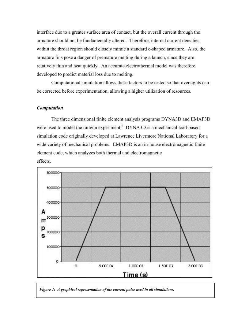
Figure 1: A graphical representation of the current pulse used in all simulations.

A model of the armature and a section of rail for the simulation was constructed
using MSC Patran. Electromagnetic conditions were specified by assigning a magnetic
tangential flux to the surface above the rail gun, and an electric pulse through
the breech ends of the rail.
The model was then run through a two millisecond stationary simulation using
EMAP3D, with temperature and current density results being recorded every half
milisecond. Post-processing and visualization was done using Altair HyperMesh. All
calculations were done in quarter symmetry; to substantially reduce the computation time
involved. The current pulse used in the simulations is a linear approximation to those
found in an actual rail gun (figure 1). The results from EMAP3D provided an analysis of
the current flow through the armature and rail during the shot.
The first model constructed possessed full contact between the armature splines and rail.
The EMAP3D results show a high current density on the leading and trailing
Figure 2: Splined Armature on Grooved Rail at 0.5ms. Note the high current densities on the leadingand trailing corners.

edges of the armature (figure 2). They also reveal an extremely high current density
along the outer surface of the rail and armature during the first half milisecond of the
shot, due to the slowness of the permeation of the magnetic field into the metal of the
armature and rail. The armature was designed such that the rail does not fully come in
contact with the body of the armature, allowing the armature to expand during launch as
the armature splines wear away. However, this design had the side effect of severely
reducing and dividing the cross sectional current carrying area between the rail and the
armature body. However, the temperature distribution did not appear sufficiently high to
have melted the armature, except in the throat of the armature (figure 3).
Figure 3: Splined Armature on Grooved Rail Temperature at 2ms. Note the high temperature in the central region and themoderately low temperature at the corners.

A subsequent model was constructed with gaps between the electrical contact on
one side of the splines as would be expected in the actual experiment, since the grooves
in the rail are wider than the splines on the armature. This correlated well with the first
model, with only a slightly modified current distribution.
A model of the interdigital armature on flat copper rail was also constructed. The
gaps in the rail-armature interface should allow a faster permeation of the magnetic field
through the armature, but at the cost of higher current densities through the splines
(figure 4).
A final model was constructed of a standard c-shaped armature on the grooved
rail, and yielded similar results to the interdigital armature on flat rail.
DYNA3D was then used on the primary model with gaps in the electrical contact
to show deformation of the rail. It showed a clear deformation of the rail by purely
electromagnetic forces since the armature remained stationary (figure 5).
Figure 4: Splined Armature on Flat Copper Rail Current Density at 0.5ms. Note the high currents in thearmature splines.

Experimentation
The interdigital experiment was carried out on the IAT Medium Caliber Launcher
in mid-July 20002. Upon removal of the containment modules there was obvious
deformation of the rails. The rail material was a soft and pliable aluminum (Al 6061)
used in heat sink applications. It bent easily under the high pinch forces exerted by the
magnetic field, most notably at the edges of the rail (see figure 6). These pinches
collapsed the ridges of the rail, entrapping the splines of the armature early in the shot,
and causing them to be ripped off. The DYNA3D results closely resemble those seen
during the actual experiment, validating the use of a loosely coupled simulation.
A similar rail with greater lamina thickness has been proposed, which should
withstand the electromagnetic forces to a higher degree. This rail is currently being
modeled with the interdigital armature so that results can be obtained before further
experimentation is carried out.
Figure 5: DYNA3D results showing deformation of the rail.

Conclusion
A loosely coupled finite element model has been shown to closely correspond
with physical experimentation in electromagnetic launchers. Further development of
these modeling systems could allow new methods of analysis and allow concepts to be
tested before experiments are performed.
List of Figures
Figure 1: Splined Armature on Grooved Rail at 0.5ms. Note the high current densitieson the leading and trailing corners.
Figure 2: Splined Armature on Grooved Rail Temperature at 2ms. Note the hightemperature in the central region and the moderately low temperature at the corners.
Figure 3: Splined Armature on Flat Copper Rail Current Density at 0.5ms. Note the highcurrents in the armature splines.
Figure 7: A graphical representation of the current pulse used in all simulations.
Figure 5: DYNA3D results showing deformation of the rail.
Figure 6: A picture of the rail, post-experiment. Note the folding effects and the piecesof splined armature (labeled A-F). The arrow points towards the gun breech.
Figure 6: A picture of the aluminum grooved rail, post-experiment. Note the folding effects and thepieces of splined armature (labeled A-F). The arrow points towards the gun breech.

References iStefani, F., Levinson, S., Satapathy, S., and Parker, J. "Electrodynamic Transition in Solid Armature
Railguns," IEEE Transactions on Magnetics, Vol. 37, No. 1, January 2001.ii K. T. Hsieh, “A Lagrangian Formulation for Mechanically, Thermally Coupled Electromagnetic
Diffusive Processes with Moving Conductors.” IEEE Transactions on Magnetics, Vol. 35, No.1, 1999.