Embed Size (px)
Citation preview

GrayhoundWear CheckGuide Book
21085 (10/00) Part # 49999-151
A Terex Company


21085 (10/00) i
Grayhound Wear Check Guidebook
A Terex Company
FEEDER SYSTEM .................................................................................................................................... 1Conveyor Deck Liners ................................................................................................................. 1Skirt Boards .................................................................................................................................. 1
Grayhound Wear Check GuideBook .......................................................................................................... 2Front Conveyor Idlers .................................................................................................................. 2Conveyor Drive Shafts and Sprockets ......................................................................................... 2Conveyor Chain and Slat Bars ..................................................................................................... 3
Conveyor Chain ............................................................................................................. 3Roller Wear .................................................................................................................... 4Conveyor Chain Adjustment. ........................................................................................ 4
Conveyor Chain Skates ................................................................................................................ 4Auger Drive Shafts and Sprockets ............................................................................................... 4Auger /Conveyor Drive Chain ..................................................................................................... 5Auger/Conveyor Bearings ............................................................................................................ 6Augers (Standard) ........................................................................................................................ 6Augers (Lined) ............................................................................................................................. 7
DRIVE SYSTEM CR561, CR461, CR361 ................................................................................................ 7Front Track Idlers ......................................................................................................................... 8Track Drive Sprockets ................................................................................................................. 9
CR561 Track Drive Sprocket Template ..................................................................................................... 11CR461 Track Drive Template .................................................................................................................... 13CR361 Track Drive Sprocket Template ..................................................................................................... 15
Track Rollers ................................................................................................................................ 17Three Roller Bogie CR361 and CR461 ....................................................................................... 17Track Chain .................................................................................................................................. 17Track Pads .................................................................................................................................... 18Final Drive ................................................................................................................................... 19
DRIVE SYSTEM CR551, CR451, CR351 ................................................................................................ 19Rear Drive Tires ........................................................................................................................... 19Front Bogie .................................................................................................................................. 20Steering Linkage .......................................................................................................................... 20Final Drive and Frame Raise ....................................................................................................... 20
ENGINE and DRIVE ................................................................................................................................. 21Radiator and Oil Cooler ............................................................................................................... 21Engine Fan Belts .......................................................................................................................... 21Air Cleaner ................................................................................................................................... 22Engine Oil and Filters .................................................................................................................. 22Engine Coolant ............................................................................................................................. 22Pump Drive Belts ......................................................................................................................... 22
V-Belts ........................................................................................................................... 22Poly Chain Belts ............................................................................................................ 23
Engine Tune-up ............................................................................................................................ 24Load Adapters (500 series w/ 8.2 Detroit) ................................................................................... 24
HYDRAULIC SYSTEM ............................................................................................................................ 24Hydraulic Tank(s) ........................................................................................................................ 24Hydraulic Filters .......................................................................................................................... 25Traction Pump and Motor ............................................................................................................ 25Front Wheel Assist ....................................................................................................................... 25Brake System ............................................................................................................................... 25Conveyor Pump and Motor .......................................................................................................... 25
Table of Contents

21085 (10/00) ii
Grayhound Wear Check Guidebook
A Terex Company
Table of Contents
Auxiliary System .......................................................................................................................... 25Screed Lift and Screed Assist ........................................................................................ 25Hopper ........................................................................................................................... 25Tow Points ..................................................................................................................... 26Steering (Rubber Tired) ................................................................................................. 26Frame Raise ................................................................................................................... 26Screed Extend/Retract ................................................................................................... 26Match Height ................................................................................................................. 26Crown ............................................................................................................................ 26Screed Slope .................................................................................................................. 26
Vibrator System ........................................................................................................................... 27ELECTRICAL SYSTEM ........................................................................................................................... 27
Automatic Grade and Slope ......................................................................................................... 27TRACTOR ................................................................................................................................................. 28
Push Rollers and Truck Hitch ...................................................................................................... 28Tow Arm Buffer Plates ................................................................................................................ 28Hopper Flashing and Hopper Wing Seals .................................................................................... 29
SCREED ..................................................................................................................................................... 29Screed Bottoms ............................................................................................................................ 29
Stretch 20 ....................................................................................................................... 29Fastach 10' and 8' ......................................................................................................................... 30Screed Heaters .............................................................................................................................. 31Fixed Strike-offs .......................................................................................................................... 31Hydraulic Strike-offs (Fastach 10' and 8') .................................................................................... 32

21085 (10/00) - 1 -
Grayhound Wear Check Guidebook
A Terex Company
Conveyor Deck Liners
The 400 and 500 series Grayhound Pavers are equipped with segmented High Alloy deck liners to provide extended lifeand reduced costs in the most severe of operational conditions. High Alloy deck liners are 3/8 inch (9.53mm) thick whennew. When worn to approximately 1/8 inch (3.18mm) they should be replaced.
The 300 series Grayhound Pavers are equipped with High Alloy deck liners to provide extended life and reduced costs in themost severe of operational conditions. High Alloy deck liners are 1/4 inch (6.35mm) thick when new. When worn to approximately1/8 inch (3.18mm) they should be replaced.
Skirt Boards
The skirt boards that are installed in the feeder chamber are normally field repaired when wear occurs. This is usually doneby welding wear strips to the worn areas.
Feeder System
1/4"

21085 (10/00) - 2 -
Grayhound Wear Check Guidebook
A Terex Company
Front Conveyor Idlers
The 400 & 500 series Grayhound pavers have 6 3/4 inch (171.45mm) OD front idlers that are heat treated to a depth of 3/16 inch (4.76mm). They should be checked seasonally for wear. When the wear has decreased the OD to 6 3/16 inch(161.93mm) they should be replaced as shown in the illustration below.
The 300 series Grayhound pavers have 6 1/2 inch (165.1mm) OD front idlers that are heat treated to a depth of 3/16 inch(4.76mm). They should be checked seasonally for wear. When the wear has decreased the OD to 6 1/8 inch (155.58mm)they should be replaced as shown in the illustration below.
The idler shafts will show worn areas where it goes through the frame. These worn areas are normal and do not hurt theshaft.
Normal Wear
Conveyor Drive Shafts and Sprockets
The 400 and 500 series Grayhound pavers have 8-tooth conveyor drive sprockets that are heat treated (hardened) to aminimal depth of 1/8 inch (3.18mm) as the shaded areas in the illustration below show. These sprockets are reversible toprovide extended life and lower operating cost.
Wear occurs on one side of the sprocket in normal use as the illustration below shows. It is recommended that the amountof wear be checked periodically during the paving season. When the sprockets show approximately 1/8 inch (3.18mm) wearthey should be reversed. This is done by removing the conveyor drive shaft assembly and swapping the LH assembly withthe RH assembly. The conveyor sprocket bearings should be checked for wear or damage. Refer to Auger/Conveyor Bear-ings.
New Reverse
Normal Wear
Feeder System
21085 (10/00) - 3 -
Grayhound Wear Check Guidebook
A Terex Company
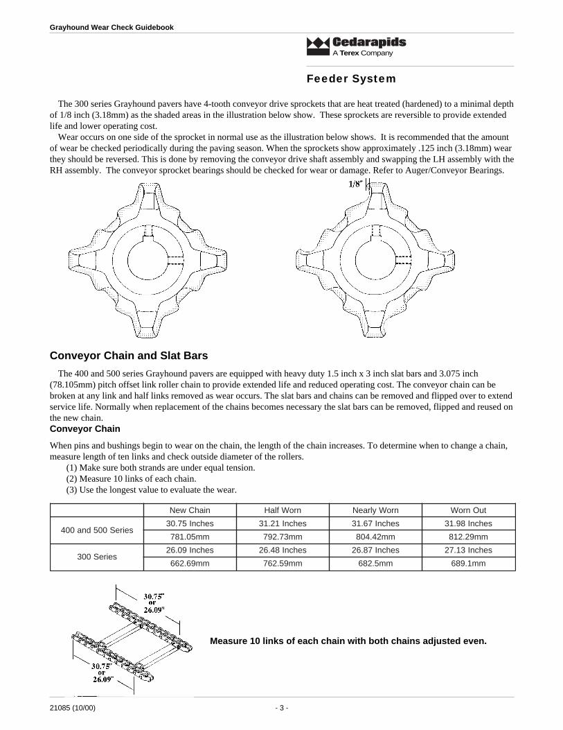
The 300 series Grayhound pavers have 4-tooth conveyor drive sprockets that are heat treated (hardened) to a minimal depthof 1/8 inch (3.18mm) as the shaded areas in the illustration below show. These sprockets are reversible to provide extendedlife and lower operating cost.
Wear occurs on one side of the sprocket in normal use as the illustration below shows. It is recommended that the amountof wear be checked periodically during the paving season. When the sprockets show approximately .125 inch (3.18mm) wearthey should be reversed. This is done by removing the conveyor drive shaft assembly and swapping the LH assembly with theRH assembly. The conveyor sprocket bearings should be checked for wear or damage. Refer to Auger/Conveyor Bearings.
Conveyor Chain and Slat Bars
The 400 and 500 series Grayhound pavers are equipped with heavy duty 1.5 inch x 3 inch slat bars and 3.075 inch(78.105mm) pitch offset link roller chain to provide extended life and reduced operating cost. The conveyor chain can bebroken at any link and half links removed as wear occurs. The slat bars and chains can be removed and flipped over to extendservice life. Normally when replacement of the chains becomes necessary the slat bars can be removed, flipped and reused onthe new chain.Conveyor Chain
When pins and bushings begin to wear on the chain, the length of the chain increases. To determine when to change a chain,measure length of ten links and check outside diameter of the rollers.
(1) Make sure both strands are under equal tension.(2) Measure 10 links of each chain.(3) Use the longest value to evaluate the wear.
Measure 10 links of each chain with both chains adjusted even.
Feeder System
niahCweN nroWflaH nroWylraeN tuOnroW
seireS005dna004sehcnI57.03 sehcnI12.13 sehcnI76.13 sehcnI89.13
mm50.187 mm37.297 mm24.408 mm92.218
seireS003sehcnI90.62 sehcnI84.62 sehcnI78.62 sehcnI31.72
mm96.266 mm95.267 mm5.286 mm1.986

21085 (10/00) - 4 -
Grayhound Wear Check Guidebook
A Terex Company
Roller Wear
Rollers will wear at the middle part (the “apple core” area). Worn rollers do not normally limit the chain life, but chainsshould be replaced when rollers show excessive wear. The figures below apply to the 400 and 500 series pavers. Measure-ments are to be taken at the midpoint of the roller.
Roller OD: New Chain - 1.25 inch (31.75mm), Half Worn - 1.12 inch (28.45mm), Nearly Worn - 1.00 inch (25.4mm),Worn Out - Worn through wall thickness.
Inverting the chain may extend wear life. When replacing the chain, always replace both strands and install new sprockets.
Conveyor Chain Adjustment.
The conveyor chain should be adjusted when 1 inch (2.4mm) of sag below the bottom of the paver frame is noted. Adjustthe chains so the top of the chain is even with the bottom of the frame. Over tightening the chains introduces added wear tothe chain, front idlers, drive sprockets and all bearings.
Conveyor Chain Skates
Conveyor chains skates are heat treated to a depth of 1/4 inch (6.35mm). They should be checked several times during thepaving season. If wear is allowed to proceed past the heat treated area the rate of wear will be very high. Replace when wornas illustrated below.
Auger Drive Shafts and Sprockets
The auger/conveyor drive chains and bronze spacer washer are subject to stretching and wear when not properly lubri-cated. Since the chains and spacer is housed in a case to keep them clean, they are not exposed for regular nightly spray-downand lubrication. Therefore give them extra attention during the regular maintenance checks.
Feeder System
21085 (10/00) - 5 -
Grayhound Wear Check Guidebook
A Terex Company
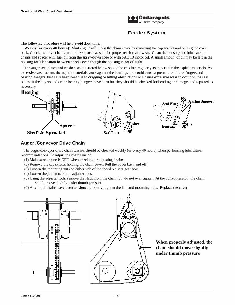
The auger seal plates and washers as illustrated below should be checked regularly as they run in the asphalt materials. Asexcessive wear occurs the asphalt materials work against the bearings and could cause a premature failure. Augers andbearing hangers that have been bent due to dragging or hitting obstructions will cause excessive wear to occur on the sealplates. If the augers and or the bearing hangers have been hit, they should be checked for bending or damage and repaired asnecessary.
The following procedure will help avoid downtime.Weekly (or every 40 hours): Shut engine off. Open the chain cover by removing the cap screws and pulling the cover
back. Check the drive chains and bronze spacer washer for proper tension and wear. Clean the housing and lubricate thechains and spacer with fuel oil from the spray-down hose or with SAE 10 motor oil. A small amount of oil may be left in thehousing for lubrication between checks even though the housing is not oil tight.
Auger /Conveyor Drive Chain
The auger/conveyor drive chain tension should be checked weekly (or every 40 hours) when performing lubricationrecommendations. To adjust the chain tension:
(1) Make sure engine is OFF when checking or adjusting chains.(2) Remove the cap screws holding the chain cover. Pull the cover back and off.(3) Loosen the mounting nuts on either side of the speed reducer gear box.(4) Loosen the jam nuts on the adjuster rods.(5) Using the adjuster rods, remove the slack from the chain, but do not over tighten. At the correct tension, the chain
should move slightly under thumb pressure.(6) After both chains have been tensioned properly, tighten the jam and mounting nuts. Replace the cover.
When properly adjusted, thechain should move slightlyunder thumb pressure
Feeder System

21085 (10/00) - 6 -
Grayhound Wear Check Guidebook
A Terex Company
The 400 and 500 series Grayhound pavers have #140, the 300 series Grayhound pavers have #120 chain to provide ex-tended life and reduced operational cost.Measured over 10 Pitches400 and 500 Series: New - 17.5 inch, Worn - 18.025 inch300 Series: New - 15 inch, Worn - 15.45 inch
Auger/Conveyor Bearings
Grayhound pavers have all conveyor bearings placed on the outside of the frame or inside protected areas so bearing lifeand operational cost is reduced. The only bearings that are in contact with the asphalt are the outboard auger bearings.
Proper lubrication and daily cleaning is one of the most important factors in bearing life. Follow the recommended lubrica-tion charts as per machine. Be sure to clean all grease zerks and grease gun tip before greasing. During your daily cleaningand lubrication procedures, inspect the seal area for signs of a blown seal. Over-greasing or greasing when the bearings arecold is the biggest reason for blown seals.
During seasonal repairs, close inspection of all bearings will normally show any that have questionable seals or wear.Replacement of the bearing insert is normally the only repair required as the bearing housing can be used again. This saveson repair costs.
Augers (Standard)
The 300 series Grayhound is equipped with standard augers with hard facing stripes. Optional High Alloy lined augers areavailable when severe operational conditions exist. The amount of wear occurring on the auger should be noted daily. Whenthe hard facing stripe has been worn off the auger can be removed and refaced using a welder and a hard facing rod.High Alloy liners and shaft shields can be installed easily on standard augers.
Feeder System

21085 (10/00) - 7 -
Grayhound Wear Check Guidebook
A Terex Company
Augers (Lined)
The 400 and 500 series Grayhound pavers are equipped with 3/8 inch (9.53mm) thick heavy duty lined augers forextended life and reduced operational cost. The augers should be inspected during daily cleanup to note wear and any impactdamage. Once the liners have worn to 1/8 inch (3.18mm) thick the auger can be removed and relined with new liners andshaft shields. The liners are welded on using 7018 (low hydrogen) welding rod.
There are various reasons to measure wear on crawler paver undercarriage parts:� functional safety for operators� ensuring trouble free operation� cost per hour calculation of undercarriage wear parts for costing and comparison� pre-determination of expected life of undercarriage parts, rebuild and replacement points.Track wear measurement should be planned in advance and carried out regularly as follows:� after every approx. 500 hours of operation� when operators are changed� to ascertain if replacement of undercarriage parts is necessaryMeasurements to be taken:
Track link heightTrack pad heightBushing outside diameterTrack pitchTrack and top roller tread diameterIdler tread diameter
Measurements can be compared with new/replace dimensions as per tables enclosed.While taking wear measurements, attention must be paid to abnormal wear factors such as:� excessive spalling of wear and guiding surfaces� abnormal deformation of wear surfaces indicating possible “soft” spots on wear surfaces� cracks in hardened contact surfaces or in areas under bending stress� one sided wear on lateral guiding surfaces (e.g. track and top roller flange, idler flange, sprocket sides, track link inside
and outer gauge)� unusual wear of sprocket teeth� bent track shoes� tightness of track shoe hardware by random checking using operators torque wrench� bolt heads� leaking rollers� vertical and lateral idler play� track pitch� lateral play of track link assembly and wear of master pin or master lock if track link assembly has been opened for some
reasonAlways consider both measurement and general condition of undercarriage in your decision making. Use the following tablesand record the measurements for later comparison of wear.
Drive SystemCR561, CR461, CR361

21085 (10/00) - 8 -
Grayhound Wear Check Guidebook
A Terex Company
Front Track Idlers
Cedarapids track pavers are equipped with heat treated front track idlers for extended life and reduced operational cost.Normal maintenance is no more than visual inspection for seal leakage and then seasonal checks for wear. Follow the chartand illustrations below to determine wear. To extend idler life the tracks should be tensioned properly. Loose or overly tighttracks introduces undue wear.
IdlerUse a depth gauge or ruler measure to measuredistance between center flange and tread.
Drive SystemCR561, CR461, CR361
ledoMrevaP rebmuNtraP weN nroW
163RC 98-750-4079 mm61.81/hcni517. mm96.72/hcni90.1
163RC 21-200-01654 mm30.81/hcni17. mm26.32/hcni39.
164RC 07-650-4079 mm61.81/hcni517. mm96.72/hcni90.1
164RC 31-200-01654 mm2.81/hcni27. mm9.62/hcni60.1
165RC 39-650-4079 mm1.83/hcni5.1 mm36.74/hcni578.1
165RC 41-200-01654 mm95.12/hcni58. mm12.92/hcni51.1

21085 (10/00) - 9 -
Grayhound Wear Check Guidebook
A Terex Company
Track Drive Sprockets
Cedarapids Grayhound track pavers are equipped with one piece bolt-on drive sprockets that are heat treated. Normal wearoccurs on one side of the tooth, traditionally on the side that pulls the track forward. Normally a set of sprockets can bereversed or flipped before any track rail repair (turning pins and bushings) is required.
The CR561 track drive sprocket is heat treated to a depth of .1875inch (4.76mm) and the CR461 and CR361 sprockets are heat treatedto a depth of .125 inch (3.18mm). The sprockets should be reversedwhen the wear is at this point, as the rate of wear increases very fastafter the heat treated area has been worn through. Increased wearalso occurs in the track rail bushings, thereby shorteing their life.Track tension also plays an important part in extending the life of atrack system. Tracks that are too loose or tight increase the amountof wear occurring. To achieve maximum possible life, the tracktension should be checked and adjusted as necessary.
Use the correct template to measure wear as illustrated
Checking Wear
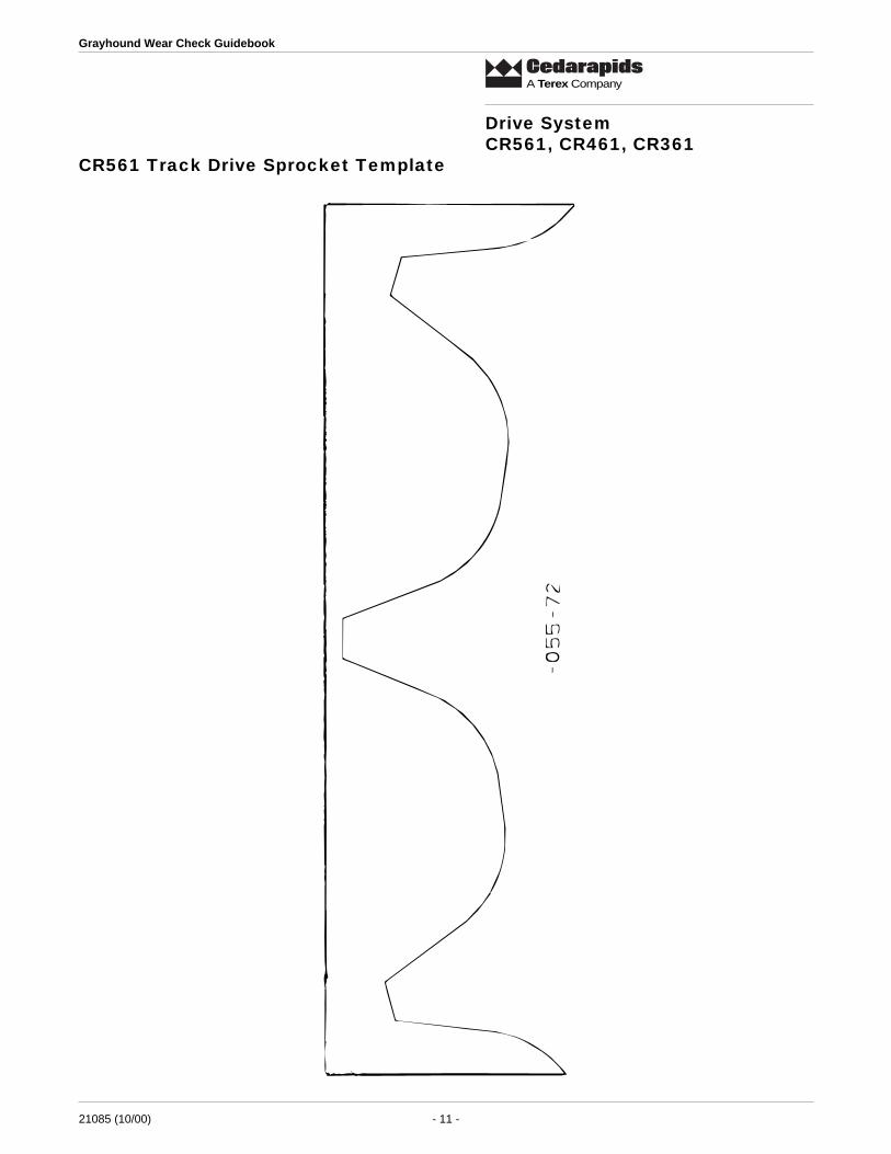
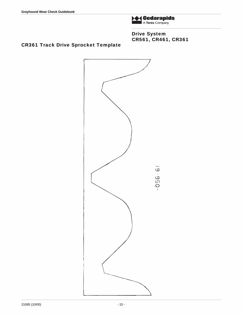
Wear is checked as illustrated and by using the Wear Check Templates provided.1. Remove the correct template for the model of paver being checked.2. Cut the template out using care to cut on the outside of the line.3. Place the template over the sprocket and measure the wear.4. The table below shows the allowable wear before reversing the sprockets.
Measurments: CR561: .1875 inch/4.76mm; CR461: .125 inch/3.18mm; CR361: .125 inch/3.18 mm
Drive SystemCR561, CR461, CR361

21085 (10/00) - 10 -
Grayhound Wear Check Guidebook
A Terex Company
Drive SystemCR561, CR461, CR361
21085 (10/00) - 11 -
Grayhound Wear Check Guidebook
A Terex Company
CR561 Track Drive Sprocket Template
Drive SystemCR561, CR461, CR361

21085 (10/00) - 12 -
Grayhound Wear Check Guidebook
A Terex Company
Drive SystemCR561, CR461, CR361

21085 (10/00) - 13 -
Grayhound Wear Check Guidebook
A Terex Company
CR461 Track Drive Sprocket Template
Drive SystemCR561, CR461, CR361

21085 (10/00) - 14 -
Grayhound Wear Check Guidebook
A Terex Company
Drive SystemCR561, CR461, CR361
21085 (10/00) - 15 -
Grayhound Wear Check Guidebook
A Terex Company
CR361 Track Drive Sprocket Template
Drive SystemCR561, CR461, CR361

21085 (10/00) - 16 -
Grayhound Wear Check Guidebook
A Terex Company
Drive SystemCR561, CR461, CR361

21085 (10/00) - 17 -
Grayhound Wear Check Guidebook
A Terex Company
Drive SystemCR561, CR461, CR361
Track Rollers
The CR561 Grayhound paver uses B4 class track rollers and the CR461 and CR361 Grayhound pavers use B3 class trackrollers for extended life and reduced operational cost. Normal maintenance requires visual inspection for seal leakage, andseasonal should include measurement of wear.
Top RollerNew 4.0 inch (101.6mm)Worn 3.62 inch (91.9mm)
Track RollersUse outside calipers to establish most worn tread diameterand read off dimension from ruler as illustrated
Track Roller Wear GuideCR561 Track Rollers: New - 6.10 inch/155.0 mm; Worn - 5.51 inch/140.0 mmCR461 and CR361 Track Rollers: 5.98 inch/152.0 mm; Worn - 5.39 inch/136.0 mm
Three Roller Bogie CR361 and CR461
The CR361 and CR461 pavers are equipped with a 3-roller rear bogie assembly. Through normal usage wear occurs in thetop rear edge of the bogie frame. As wear occurs, the machine weight is shifted further towards the rear of the machine. Thiscauses a rougher ride. The areas of wear can be built up using a welder and 7018 Low Hydrogen rod.
Track Chain The CR561 is equipped with B4 loader type track rails and the CR461 and CR361 are equipped with B2 loader type trackrails to provide extended life and reduced cost in the most severe conditions. The loader type track rails are not effected byoil, fuel or asphalt which are commonly encountered in normal operation conditions. The only maintenance required isperiodic adjustment of the track tension.
The normal procedures for track repair (turning pins and bushings) or replacement are:(1) The first thing to wear is the drive sprockets. Keep track of the wear and reverse the sprockets.(2) After the reverse side of the drive sprockets are worn out, check track rails (length over 4 links, bushing OD) forwear. At this point the track rails can be removed and have the pins and bushings turned. This allows the rails to bereinstalled along with new drive sprockets.
There are many local equipment companies in most areas that can easily turn pins and bushings. By having the pins andbushings turned you will be able to get the maximum possible life, thereby reducing operational costs.

21085 (10/00) - 18 -
Grayhound Wear Check Guidebook
A Terex Company
Drive SystemCR561, CR461, CR361
Follow the illustrations and tables below to check wear.
Track LinkUse depth gauge and meausrethe height of link.
Pin and Bushing Internal WearTighten tracks, use tape to measure over four links
Bushing Outside WearUse outside calipers to measuremaximum wear points.
Track Pads The CR561 and CR461 are equipped with 18-inch wide polyurethane track pads and the CR361 is equipped with 14-inchwide polyurethane track pads to provide extended wear life and reduced operational cost. The rate at which a track pad wears is highly dependent on operational conditions and the manner in which the paver isoperated. Existing grade conditions (large sharp stones, water drains, manhole covers. etc.) and sharp turns introduce cuttingor “chunking” in the track pads. This cutting or “chunking” normally does not affect the performance of the pad. Track pads are considered worn when the top of the grosser bars are exposed across the full width of all the pads. A givenpad may have part of the grosser bars exposed due to cutting or “chunking” , but as long as the adjacent pads do not have thegrossers fully exposed it does not affect the performance of the track as a whole.
NEW
Worn when grossers are fully exposed
thgieHkniL DOgnihsuB )skniL4(htgneL
dna163RC164RC
WEN mm0.77/hcni420.3 mm58.24/hcni96.1 mm3.326/sehcni45.42
NROW mm0.07/hcni57.2 mm0.63/hcni24.1 mm5.536/sehcno20.52
165RCWEN mm5.49/hcni27.3 mm6.05/hcni99.1 mm3.586/sehcni89.62
NROW mm0.68/hcni93.3 mm0.34/hcni96.1 mm5.796/sehcni64.72

21085 (10/00) - 19 -
Grayhound Wear Check Guidebook
A Terex Company
Final Drive
The Grayhound traction drive system is Direct Hydraulic Drive which eliminates about 70% of the moving componentstraditionally found in pavers. This relates to a direct reduction in operational costs and extended life. The final drive units arevery low maintenance. The only requirements are inspection for any oil leakage and seasonal replacement of the gear oil.
Final DriveDrain and Flush with solvent, refill with 90W gear oil.
Drive SystemCR551, CR451, CR351
Rear Drive TiresOne of the unique features of the Grayhound rubber tired pavers are the large, high flotation drive tires. The drive tires in
combination with the Frame Raise capability dramatically increase traction effort, thereby extending life and loweringoperational costs.
The tire pressure should be checked and maintained at 32 PSI. Both tires should be set to the same pressure for bestperformance. During normal inspection of the paver, check tires for wear, cuts or any bubbles or knots.
Normal operations do not require Hydroflation of the drive tires to maintain traction. If severe operational conditions exist thetires can be hydroflated. Use the table below for determining the correct amount of calcium chloride and water.
153RC 154RC 155RC
eziSeriT hcni62x4.81 hcni62x1.32 hcni23x5.42
thgieWsdnuopni
muiclaC 642 683 544
retaW 685 709 0601
snollaGSU 3.07 7.801 20.721
)sdnuop(thgieWlatoT 238 7821 5051
Grayhound
Tires32 PSI

21085 (10/00) - 20 -
Grayhound Wear Check Guidebook
A Terex Company
Front Bogie The front tires used on Grayhound rubber tired pavers normally only require visual inspection to determine damage orwear. Method of operation and grade conditions along with steering linkage adjustment are some of the factors that deter-mine rate of wear. Normally the front tires are considered worn if they are worn smooth and show no center grooves.
Drive SystemCR551, CR451, CR351
Steering Linkage
The steering linkage, rod ends, bushings, bearings and cylinders should be checked seasonally for wear. The wheel andpivot bearings should be repacked during this time. Wheel alignment and amount of tow-in should be adjusted as necessary.
Check steering linkage rod ends, bushings,bearings and steering cylinder.
Check and adjust steering wheelalignment and tow-in.
Final Drive and Frame Raise
The Grayhound rubber pavers traction drive system is Direct Hydraulic Drive which eliminates about 70% of the movingcomponents traditionally found in pavers. This relates to a direct reduction in operational costs and extended life. The finaldrive units are very low maintenance. The only requirements are inspection for any oil leakage and seasonal replacement ofthe gear oil. The frame raise on the CR351 and CR451 should also be greased seasonally.
Clean the Frame Raise system of all built-up asphalt.
Grease CR351 and CR451 slide components.
Drain and flush Final Drive and refill with 90 W gear oil.

21085 (10/00) - 21 -
Grayhound Wear Check Guidebook
A Terex Company
Radiator and Oil Cooler
The radiator and oil cooler should be checked daily for dirt and other buildup that would restrict the air flow. The pavingconditions will determine how often the radiator and oil cooler require cleaning. If severe conditions exist or there are a lot ofair-born contaminates the radiator and oil cooler will require more attention. Any leaks occurring from any engine compart-ment component, hose or tube will find its way into the radiator and oil cooler. When cleaning, check between the radiatorand oil cooler for buildup.
Engine and Drive
Radiator and Oil CoolerShould be Checked Daily
Check not only the exposed areas but the areabetween the radiator and oil cooler
Engine Fan BeltsThe engine fan and alternator belts should be checked periodically for correct tension and weathered or worn belts. Belts
that are not adjusted properly allow slippage which shortens the life of the belt and can effect the cooling and chargingsystems.
Engine fan and alternator beltsshould be checked periodically for proper
adjustment and wear.

21085 (10/00) - 22 -
Grayhound Wear Check Guidebook
A Terex Company
Air Cleaner
The engine air cleaner is equipped with an indicator that trips red when it needs service. The indicator should be checkeddaily to ensure proper servicing. Running the paver with an air cleaner that needs replacement does not allow the engine toget the proper amount of air to burn the fuel properly, thereby reducing engine horsepower output.
When servicing an air cleaner take precautions not to allow any of the dirt or contamination that would happen to fall offthe old element to remain in the filter housing or pass into the air inlet of the engine. Dirt and contamination are one of thebiggest reasons for engine wear.
Improper cleaning of old air cleaner elements can damage the element and allow dirt and contamination to pass directlyinto an engine.• Do not beat or bang an element against something in an attempt to shake the dirt out. This will damage the
element.• Do not use high pressure air in an attempt to blow the dirt out. This will damage the element.
Check Air Cleaner Indicator Daily
Do Not Beat or Bang Element
Do Not Use High Pressure Airon Element
Engine Oil and Filters The engine oil level should be checked daily. Follow engine manufacturer’s recommendations on oil change intervals andSAE grade of oil. Refer to the engine manuals provided with the paver.
Engine CoolantThe coolant level should be checked daily. The radiator should never be filled totally to the top. There has to be some room
for fluid expansion. The correct cold level is normally even with the baffle, which is located just below the fill port. Thecooling system should have a mixture of antifreeze and water for proper protection in freezing weather. The pavers have a 50/50 mixture of antifreeze and water when shipped new. Follow engine manufacturer’s recommendations for various weatherconditions.
Pump Drive BeltsThe Grayhound pavers use V-belts or Poly Chains to drive the hydraulic pumps. This greatly reduces the costs and
maintenance traditionally related to gear box type drive systems. Seasonal maintenance requires only a fraction of the timeand expense compared to repair of a gear box type. If a belt failure does occur, new V-belts or Poly chains can be installedquickly.
V-BeltsWhen installing new V-belts, adjust to NEW setting. Adjustments after that will be set to the NORM setting. New V-belts
should be checked and adjusted according to the chart after eight hours of operation. Do not adjust belts until they test belowNORM setting. Adjust up to, but not exceeding, the NORM setting. All V-belt adjustments are made at 3/8 inch belt deflec-tion.
Engine and Drive

21085 (10/00) - 23 -
Grayhound Wear Check Guidebook
A Terex Company
Common-Sense Rules of Belt Tensioning
• The ideal tension is the lowest tension at which the belt will not slip under peak load conditions• Check the belt tension frequently during the first 24 to 48 hours of run-in operation.• Do not over-tension belts. This shortens belt and bearing life.• Keep belts free of foreign material which may cause slippage.• Inspect drive periodically. Retention the belts before they start slipping.• Maintain sheave alignment with a strong straight-edge tool while tensioning belts.
V-Belts
Check at 1/4 inch Deflection400 and 500 Series: Minimum (at Operating Temp) - 18 lbs.; Maximum (at Operating Temp) - 20 lbs.
Poly Chain BeltsTension values for Poly chain belts are temperature-sensitive. When installing belts, either new or used, adjust the belts for
an 8- to 10- lb. setting at 1/4 inch deflection when belts are cold. After the machine is at normal operating temperature, theyshould be checked and readjusted if necessary, using the values listed in the table.
Do not adjust the belts until they test below the MINIMUM setting when the machine is at NORMAL operatingtemperature. The values in the table are for normal operating temperatures. Adjusting cold belts to these values willresult in rapid belt failure and possibly damage the pump bearings.Adjust up to (but not exceeding) the MAX. setting when the machine is at normal operating temperature.
All Poly chain adjustments are to be at 1/4 inch deflection.
Engine and Drive
8/3tateserastleb-VllAnoitcelfedhcni
seireS003 seireS004 seireS005
lamroN weN lamroN weN lamroN weN
retseTelacStekcoP .sbl71 .sbl02 .sbl71 .sbl02 .sbl71 .sbl02
retseTelacS-lluP .sbl43 .sbl04 .sbl05 .sbl06 .sbl86 .sbl08

21085 (10/00) - 24 -
Grayhound Wear Check Guidebook
A Terex Company
Engine Tune-up
Follow the engine manufacturer’s recommendations for adjustment of valves, calibration of injection system, etc. to keepthe engine operating properly.
Load Adapters (500 series w/ 8.2 Detroit)
500 series Grayhound pavers equipped with the 8.2 Detroit engine have load adapters between the hydraulic pumps and theV-belt drive. The oil level should be checked daily and changed seasonally.
Hydraulic System
Check oil level Daily.
Change Seasonally.
The hydraulic fluid level should be checked daily and the correct replacement fluids added if necessary. In general, forseasonal maintenance, inspect all hydraulic lines and tubes for leakage or areas that show wear on the tube or hose.
Hydraulic Tank(s)
The hydraulic fluid should be drained and replaced with the correct fluid seasonally. Check all hose and tube connections,to ensure tight connection. There are suction screens, suction filters and return filters on various models that should becleaned or replaced.

21085 (10/00) - 25 -
Grayhound Wear Check Guidebook
A Terex Company
Hydraulic FiltersVarious models of Grayhound pavers have high pressure auxiliary filters and charge pressure filters for the traction and
conveyor systems. These filters should be checked periodically and changed according to the lubrication charts provided witheach paver.
Traction Pump and MotorDuring seasonal maintenance the traction system should be checked to ensure proper operation. It is a good idea to check
and record the charge, POR, forward relief and reverse relief pressures. This information can become useful in trackingsystem wear or problems that might occur.
Front Wheel AssistDuring seasonal maintenance the front wheel assist system on rubber tired pavers if equipped should be checked to ensure
proper operation. Visual inspection of the front wheel drive motors for external leakage and inspection of all steering leakageis recommended.
Brake SystemDuring seasonal maintenance the brake system should be checked to ensure proper operation. Refer to Operation and
Maintenance Manual for procedures on how to engage the brakes for testing against the traction system.
Conveyor Pump and Motor
During seasonal maintenance the conveyor systems should be checked to ensure proper operation. It is a good idea tocheck and record the charge and forward relief pressures. This information can become useful in tracking system wear orproblems that might occur.
Auxiliary System
Screed Lift and Screed Assist
During seasonal maintenance the screed lift and screed assist systems should be checked to ensure proper operation.Clean off any asphalt that has built up over the season. The screed assist accumulator should be checked for the correct 175PSI nitrogen precharge.
Hopper
During seasonal maintenance the hopper wing lift system should be checked to ensure proper operation.Clean off any asphalt that has built up over the season. Visually inspect the hopper wing hinge and box for signs of wear orcracking.
Hydraulic System

21085 (10/00) - 26 -
Grayhound Wear Check Guidebook
A Terex Company
Tow PointsDuring seasonal maintenance the tow point system should be checked to ensure proper operation. Clean off any asphalt
that has built up over the season. The tow point cylinder timing should be checked and adjusted if necessary. The tow pointcylinders should fully extend in 18 seconds and fully retract in 18 seconds.
Steering (Rubber Tired)During seasonal maintenance the steering system should be checked to ensure proper operation. Clean off any asphalt that
has built up over the season. Ensure wheels have not had a history of getting out of alignment. If so, check steering cylindersfor internal leakage.
Frame RaiseDuring seasonal maintenance the frame raise system should be checked to ensure proper operation. Clean off any asphalt
that has built up over the season.
Screed Extend/RetractDuring seasonal maintenance the screed extend/retract system should be checked to ensure proper operation. Clean off any
asphalt that has built up over the season.
Match HeightDuring seasonal maintenance the screed match height system should be checked to ensure proper operation. Clean off any
asphalt that has built up over the season.
CrownDuring seasonal maintenance the screed crown system should be checked to ensure proper operation. Clean off any asphalt
that has built up over the season. Pay special attention to the V area in the center of the main screed. This is an area wherematerial tends to collect and not be cleaned out during daily clean up.
Screed SlopeDuring seasonal maintenance the screed extension or strike-off slope system should be checked to ensure proper operation.
Clean off any asphalt that has built up over the season.
Hydraulic System
21085 (10/00) - 27 -
Grayhound Wear Check Guidebook
A Terex Company
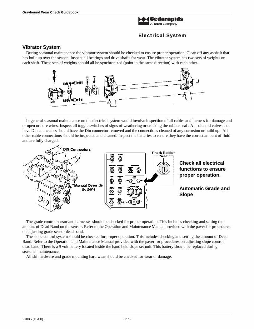
Vibrator SystemDuring seasonal maintenance the vibrator system should be checked to ensure proper operation. Clean off any asphalt that
has built up over the season. Inspect all bearings and drive shafts for wear. The vibrator system has two sets of weights oneach shaft. These sets of weights should all be synchronized (point in the same direction) with each other.
Electrical System
In general seasonal maintenance on the electrical system would involve inspection of all cables and harness for damage andor open or bare wires. Inspect all toggle switches of signs of weathering or cracking the rubber seal . All solenoid valves thathave Din connectors should have the Din connector removed and the connections cleaned of any corrosion or build up. Allother cable connections should be inspected and cleaned. Inspect the batteries to ensure they have the correct amount of fluidand are fully charged.
Check all electricalfunctions to ensureproper operation.
Automatic Grade andSlope
The grade control sensor and harnesses should be checked for proper operation. This includes checking and setting theamount of Dead Band on the sensor. Refer to the Operation and Maintenance Manual provided with the paver for procedureson adjusting grade sensor dead band.
The slope control system should be checked for proper operation. This includes checking and setting the amount of DeadBand. Refer to the Operation and Maintenance Manual provided with the paver for procedures on adjusting slope controldead band. There is a 9 volt battery located inside the hand held slope set unit. This battery should be replaced duringseasonal maintenance.
All ski hardware and grade mounting hard wear should be checked for wear or damage.

21085 (10/00) - 28 -
Grayhound Wear Check Guidebook
A Terex Company
Check sensor bead bandCheck cables for damage
Check all mounting hardware
Push Rollers and Truck Hitch
Standard equipment for the Cedarapids Grayhound series pavers is the oscillating Push-Beam. Optional equipment is theTruck Hitch. These can be prone to damage due to the type of operation they have to perform. The push-beam or truck hitchshould be periodically inspected for damage and/or asphalt buildup that would restrict operation. Seasonal close inspectionof the bearings is recommended.
When a paver is shipped from the factory the push-beam or the truck hitch is bolted to the front frame of the paver. Thisprovides for easy changing from one to the other to meet customer configuration needs. When a paver is sold with the desiredconfiguration, it is recommended to place welds in all four corners of the mount to provide the desired support.
Tow Arm Buffer Plates
The 400 and 500 series Grayhound pavers have adjustable tow arm buffer plates to keep the screed in alignment with thetractor when paving through corners or offset widths. They should be adjusted so there is a 3/4 inch gap between the tow armand the buffer plate when the screed is aligned behind the tractor.
Tractor

21085 (10/00) - 29 -
Grayhound Wear Check Guidebook
A Terex Company
Screed
Tow Arm Buffer PlatesAdjusted to3/4 inch Gap
Hopper Flashing and Hopper Wing SealsThe flashing on the front of the hoppers is extremely prone to damage due to truck operation and configuration. The
flashing should be checked regularly and repaired as necessary to prevent spillage. The hopper wing seals should be checkedand adjusted to prevent leakage of material when the hoppers are raised.
Check hopper flashing and hopper wing seals andreplace as necessary to prevent material spillage.
Screed BottomsStretch 20
The Stretch 20 screed bottoms are reversible and retained to the frames by J-bolts. This allows the bottom to be droppedand reversed in a very short period of time in comparison to other screed types. Reversal provides a means to get maximumscreed bottom life and reduce operational cost.
Cedarapids has Grade A (Premium) or Grade B (Economy) type replacement screed bottoms. The Grade A screed bottomsare standard equipment. These bottoms are made of Hardox -type material which provides a minimum of twice the wearcompared to the Grade B screed bottoms in the same operation and asphalt material design. Normal screed bottom wearshows the trailing edge wearing faster than the leading edge. When the trailing edge thickness is 1/4 inch, the screed bottomshould be dropped and reversed to get the maximum possible life. A screed bottom that shows the leading edge wearingfaster than the trailing, is indicating either operational or screed adjustments are not correct.

21085 (10/00) - 30 -
Grayhound Wear Check Guidebook
A Terex Company
Screed
Adnormal Wear
Fastach 10' and 8'The Fastach screed bottoms are retained to the frames by welded studs on the front and rear of the bottom that protrudethrough to the top of the frame. This allows the bottom to be dropped and replaced in a very short period of time in compari-son to other screed types, reducing down time when screed bottom replacement becomes necessary.
Cedarapids has Grade A (Premium) or Grade B (Economy) type replacement screed bottoms. The Grade A screed bottomsare standard equipment. These bottoms are made of High Alloy material which provides a minimum of twice the wearcompared to the Grade B screed bottoms in the same exact operation and asphalt material design. Normal screed bottom wearshows the trailing edge wearing faster than the leading edge. When the trailing edge thickness is 1/8 inch, the screed bottomshould replaced. A screed bottom that shows the leading edge wearing faster than the trailing, is indicating either operationalor screed adjustments are not correct.
mottoBdeercS"A"edarG mottoBdeercS"B"edarG
tooF01niaM02hctertS 85-665-4079 07-065-4079
tooF5raeR02hctertS 55-665-4079 18-065-4079
tooF01hcatsaF 93-965-4079 74-165-4079
tooF8hcatsaF 08-165-4079

21085 (10/00) - 31 -
Grayhound Wear Check Guidebook
A Terex Company
Screed HeatersCedarapids screeds have the most serviceable screed heaters in the industry. When service is required, flip the spring off
the four retainer clamps and rotate the clamps outward. Lift the burner head off. Using a 5/8 inch socket, remove and replacethe fuel nozzle. The glow plug is serviced from the outside. The screed heater/spray-down has a fuel filter to extend the lifeof the nozzles. There are also in-line filters for each heater on various models to add more protection. These filters should bereplaced as necessary .
The screed heaters should be checked and serviced as necessary to ensure they work properly. The Fastach screeds use thegap between the screed bottom and the frame at the trailing edge as a vent. If this is allowed to plug with material, the screedheaters will not burn properly.
Screed
Check as necessary to ensure proper operation.
Replace fuel filters as needed.
Keep vent areas clear of asphalt buildup.
Fixed Strike-offsThe fixed strike-off plates on all screeds are high wear items and should be checked regularly. They can also be damaged
or bent if the screed hits an obstruction like a water drain or a manhole cover. Normally a worn strike-off plate can beremoved and the worn area marked as illustrated and cut off.

21085 (10/00) - 32 -
Grayhound Wear Check Guidebook
A Terex Company
Hydraulic Strike-offs (Fastach 10 Foot and 8 Foot)
Daily maintenance should include cleaning off all asphalt that might get on the slide areas. The hydraulic strike-offextensions should be able to be extended and retracted without the extension drooping when extended. If it does, the wearstrips and adjusters should be checked and adjusted as necessary.
Screed