Embed Size (px)
Citation preview

A Template for Preparing Wellhead Protection Plans for Municipal Wells
Wisconsin Department of Natural Resources Bureau of Drinking Water and Groundwater
January 2000/ updated code references July 2012 PUBL DG-053-00

1
This document was produced by the Groundwater Section, Bureau of Drinking Water and Groundwater, Wisconsin Department of Natural Resources. This document is a revision of a 1994 document titled “Wellhead Protection Plans for New Municipal Wells – A Template”. Thanks to Randell Clark, Lee Boushon, Dave Lindorff, Jeff Helmuth and Norm Hahn (DNR), Gary Lueck (WRWA) and Chuck Dunning (USGS) for technical assistance and review.
2
TABLE OF CONTENTS PAGE NUMBER INTRODUCTION 3 BACKGROUND INFORMATION 4 STEP 1 - DELINEATION 4 1. DIRECTION OF GROUNDWATER FLOW 5 2. ZONE OF INFLUENCE 5 3. RECHARGE AREA 5 4. WELLHEAD PROTECTION AREA 6 STEP 2 - RISK ASSESSMENT 6 5. POTENTIAL CONTAMINATION SOURCES 6 STEP 3 - WELLHEAD PROTECTION PLAN IMPLEMENTATION 8 6. MANAGEMENT PLAN 8 7. PUBLIC EDUCATION PROGRAM 9 8. WATER CONSERVATION PROGRAM 10 9. CONTINGENCY PLAN 11 APPENDICES - A Example direction of flow documentation. 14 B Zone of influence calculations. 16 C Recharge area calculations. 25 D Wellhead protection area delineation. 27 E Example potential contamination source documentation. 31 F Example zoning ordinance. 33 G Example private well abandonment ordinance. 43 H Example sprinkling ban. 46 ATTACHMENTS 1 Wellhead Protection Contacts. 47 2 Groundwater Protection Tools. 48 3 Annotated Bibliography. 50
3
INTRODUCTION The 1986 amendments to the federal Safe Drinking Water Act (SDWA) established a nationwide program to protect groundwater used for public water supplies through establishment of state wellhead protection (WHP) programs. The goal of WHP is for communities to delineate and protect the land area, which contributes water to their wells in order to prevent contamination of their water supply wells. Wisconsin’s WHP program, approved by the U. S. Environmental Protection Agency (EPA) in 1993, has a regulatory and a voluntary component. Under the requirements of section NR 811.16(6), Wisconsin Administrative Code, all new municipal wells installed after May 1, 1992 must have a Department of Natural Resources approved wellhead protection (WHP) plan prior to placing the well into service. For wells in service on May 1, 1992, municipalities are encouraged, but not required, to develop WHP plans. The purpose of this document is to provide direction on preparation of a WHP plan to proactively protect a community’s water supply. It describes the level of detail required to address each of the nine components of a required WHP plan for new wells specified in section NR 811.16(6), Wis. Adm. Code. The nine components are divided into three primary steps in developing a WHP plan and follow a logical progression. The first primary step is delineation and includes determining the direction of groundwater flow, zone of influence, recharge area and calculating the wellhead protection area. The second major step is a risk assessment, which includes the inventory of potential contaminant sources. The last four components - developing a management plan, a public education program, a water conservation program and a contingency plan - are grouped under the third major step, wellhead protection plan implementation. For each of the nine components of a WHP plan, this document is organized to provide a brief description of the required information, followed by some example language that could appear in a WHP plan. The example language is italicized. The document should not be considered a fill-in-the-blank model for a WHP plan. It is important to remember that this is not an all-encompassing guidance document and that WHP is a unique endeavor for each community and well. Equally important, a properly prepared WHP plan should be easily read and understood by users who have no knowledge of wellhead protection. Although this template is intended for use by those municipalities which are required to prepare a WHP plan, communities with existing wells are strongly encouraged to use this document when preparing a WHP plan for their existing wells. The Department does not have the authority to approve WHP plans for existing wells, but is willing to review voluntary plans and offer assistance if requested. An important first step in the development of a wellhead protection plan is to form a committee to oversee the process and make sure that the plan is developed and implemented. Possible committee members could include representatives of the water utility; local health, fire, planning and zoning officials; farmers or business representatives; service organization representatives elected officials, and interested citizens. It is important to take advantage of the expertise within your community to identify the resources available and to gain public support for the wellhead protection effort. Educational efforts to involve the public and local media are important parts of the wellhead protection effort during all steps of the process. The Department has produced and distributed a video to aid communities in understanding wellhead protection. The video, “An Ounce of Prevention – Wellhead Protection” describes wellhead protection planning, its benefits, and the resources available to help communities take action.

4
For more information on the technical aspects of preparing a WHP plan, a contact list and an annotated bibliography are provided at the end of this document. BACKGROUND INFORMATION – While currently not required under NR 811.16, it is helpful to include some general information on the location of the well, the local geology and aquifers, the city itself and any other general information that may be useful when reading, evaluating and interpreting the wellhead protection plan. Maps of the area are always helpful, including soil maps, water table, glacial and bedrock geology maps, and a road map. It is also very useful to list studies and groundwater exploration activities that have been done in the area. EXAMPLE LANGUAGE Anywhere, Wisconsin is located north of Wisconsin Dells, in the Wisconsin River valley. The municipal water system serves 1500 people. Approximately 1/3 of the city is unsewered and relies on private septic systems. The two existing wells are located in the older unsewered portion of the city. The city is proposing to construct a new well with a capacity of approximately 350 gallons per minute. The geology of the area is glacial outwash over Cambrian sandstones. The soils of the area are droughty, light colored loamy sands. The sandy outwash thickness ranges from 40 to 60 feet in the area. The Cambrian sandstone aquifer is around 100 feet thick and consists of coarse to fine, gray to light brown sandstone. Groundwater flow in both the outwash and sandstone aquifers is generally to the west toward the river. STEP 1 - DELINEATION The delineation of a Wellhead Protection Area (WHPA) is an important step because it identifies the land area contributing water to the well, which must be managed to prevent contamination of the well. Proper delineation requires a careful analysis of the groundwater flow system and the information obtained during a pump test. An excellent discussion on conducting a pump test is contained in “Groundwater and Wells” (pages 535-554) by F. G. Driscoll. A properly run pump test will allow the calculation of aquifer parameters (Transmissivity (T), Storage Coefficient (S), and Hydraulic Conductivity (K)) necessary for a reliable calculation of the zone of influence (ZOI), the recharge area, and an effective WHPA. A single well test can determine the performance of the well and some basic information about the aquifer. However, an aquifer test involving a pumping well and several observation wells is preferred over single well tests because the calculation of a Storage Coefficient is not possible with a single well test. The four delineation steps should be done in the order listed below. Each step should be detailed and completed with the most accurate information available.

5
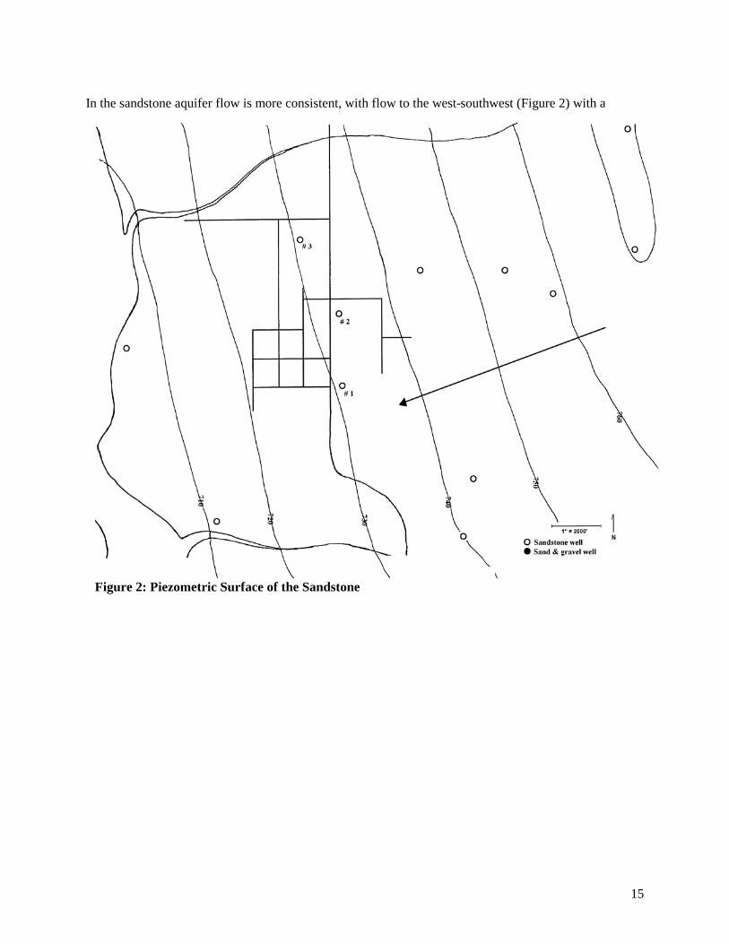
1. DIRECTION OF GROUNDWATER FLOW The direction of groundwater flow can be determined in several ways. Water-table maps for many areas of the state are available from the Wisconsin Geologic and Natural History Survey (see Attachment 1). Maps can also be developed for the area using water level data from permanent surface water bodies and wells in the area. Care should be taken to evaluate both shallow and deeper flow fields, since contamination most often originates at the surface and yet municipal wells are typically quite deep. The direction of groundwater flow should be indicated on a map and the basis for the determination should be identified. EXAMPLE LANGUAGE Groundwater flow direction was determined by using previously published maps and the addition of new wells in both the glacial and sandstone aquifers. The groundwater flow direction is west towards the Wisconsin River. The local groundwater elevations and flow direction is shown in Figure 1. Groundwater flow in the deeper sandstone aquifer, which Well #3 will draw from, is slightly to the south of west. The potentiometric surface of the sandstone aquifer is shown in Figure 2. Supporting documentation is included in Appendix A. 2. ZONE OF INFLUENCE The zone of influence, or area of the cone of depression, should be calculated (using 30 days continuous pumping at the proposed well, the normal pumping rate, and assuming no recharge). The zone of influence should be delineated on a map and all assumptions and calculations used to determine the zone of influence should be documented. See Appendix B for more information on calculating the zone of influence. EXAMPLE LANGUAGE The zone of influence (30 days continuous pumping assuming no recharge) is a circle surrounding the well with a radius of approximately 1600 feet. The extent of the zone of influence is shown in Figure 5. (In reality the circle would be elliptical, extending further upgradient and less downgradient than indicated by the calculation.) Supporting documentation and calculations are included in Appendix B. 3. RECHARGE AREA The recharge area for the well should be delineated on a map. The recharge area is the total land area contributing water to the well. The basis for this determination should be identified. The calculation should be based on the maximum expected stress to the system (pumping rate) and encompass the entire area back to the groundwater divide for that aquifer. The use of models or the Uniform Flow Equation (shown in Appendix C) is most appropriate for this, however, other methods like flow system mapping may also be used. EXAMPLE LANGUAGE

6
The recharge area extends from the well site to a ridge and associated groundwater divide located approximately 12,000 feet to the east. Calculations indicate that the capture area (recharge area) extends 1370 feet on either side of the direct flow line to the well and 440 feet in the down gradient direction. Supporting documentation is contained in Appendix C, the boundaries of the recharge area are shown in Figure 6. 4. WELLHEAD PROTECTION AREA The wellhead protection area must encompass that portion of the recharge area equivalent to a 5 year time of travel to the well. As a minimum, a 1200-foot radius must be used as the area to be incorporated as the wellhead protection area. Information on the methods available for delineating a wellhead protection area is contained in Appendix D and in several of the reports listed in the Annotated Bibliography. The wellhead protection area should be delineated on a map showing the recharge area for the well. It is not necessary to do an in field investigation to obtain the parameters used in calculating the extent of the wellhead protection area provided accurate information exists. The parameters used and the method of calculation should be documented. EXAMPLE LANGUAGE The wellhead protection area is shown in Figure 7. Supporting documentation on the method of calculation and delineation is included in Appendix D. The method used to determine the wellhead protection area is the calculated fixed radius method and encompasses an area with a 1617 foot radius around Well #3. A secondary zone identified while delineating the recharge area is outside the jurisdiction of the city. It is recognized that this is also an important area for the protection of the new well. The secondary zone will be the focus of educational efforts and strong support for appropriate land use activities. Wellhead protection areas have also been determined for the existing wells #1 and #2. The calculated radii are 965 feet and 1079 feet respectively so the default radius of 1200 feet will be used. STEP 2 - RISK ASSESSMENT Evaluating the risks to a well is an important step to management of a WHPA. This is accomplished by inventorying the existing and potential sources of contamination to the well. A thorough contaminant source inventory (CSI) will help direct management efforts in addition to responses to problems, should they arise. 5. INVENTORY OF POTENTIAL CONTAMINATION SOURCES All potential sources of contamination within ½ mile of the well site and within the recharge area should be listed along with the distance and direction from the well. It is important that the inventory cover a larger area than the WHPA to reflect the uncertainty in the delineation and to account for changes in the flow field due to stresses applied by pumping and possible altered recharge due to land use. Lists of potential contamination sources are provided in the DNR guidance for well site surveys, and on the Potential Contaminant Use Inventory Form 3300-215 Minimum separation distances to potential contamination sources are given in s. NR 811.12(5)(d), Wis. Adm. Code. Existing contaminant source information should be available from the well site inventory (for newer wells) or from the vulnerability
7
assessment maps prepared by municipalities in 1998. If a contaminant source inventory has not been completed, “A Guide to Conducting Potential Contaminant Source Inventories for Wellhead Protection” provides step-by-step procedures. The DNR Bureau of Remediation and Redevelopment has several lists of sites and activities that should be consulted. The department’s new FACT system contains facility information including air emissions, wastewater discharges, hazardous wastes generated or shipped, and toxic release inventory (TRI) data. Additionally, an assessment of the existing potential sources in the recharge area is required for new wells. Within the recharge area of the well and within a half-mile radius, the potential for actual groundwater contamination from the potential sources should be evaluated. Evaluation should include the type of potential contamination source, it’s distance from the well, the relationship to groundwater flow direction, and the ability to manage to prevent releases and minimize risk from each source.
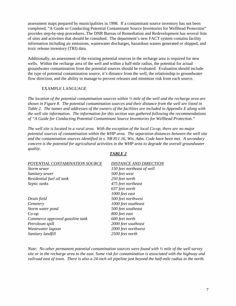
EXAMPLE LANGUAGE The location of the potential contamination sources within ½ mile of the well and the recharge area are shown in Figure 8. The potential contamination sources and their distance from the well are listed in Table 2. The names and addresses of the owners of the facilities are included in Appendix E along with the well site information. The information for this section was gathered following the recommendations of “A Guide for Conducting Potential Contaminant Source Inventories for Wellhead Protection.” The well site is located in a rural area. With the exception of the local Co-op, there are no major potential sources of contamination within the WHP area. The separation distances between the well site and the contamination sources identified in s. NR 811.16, Wis. Adm. Code have been met. A secondary concern is the potential for agricultural activities in the WHP area to degrade the overall groundwater quality.
TABLE 2 POTENTIAL CONTAMINATION SOURCE DISTANCE AND DIRECTION Storm sewer 150 feet northeast of well Sanitary sewer 500 feet west Residential fuel oil tank 250 feet north Septic tanks 475 feet northeast 637 feet north 1000 feet east Drain field 500 feet northwest Cemetery 1000 feet southeast Storm water pond 500 feet southeast Co-op 800 feet east Commerce approved gasoline tank 600 feet north Petroleum spill 2000 feet southeast Wastewater lagoon 2000 feet northwest Sanitary landfill 2500 feet north Note: No other permanent potential contamination sources were found with ½ mile of the well survey site or in the recharge area to the east. Some risk for contamination is associated with the highway and railroad east of town. There is also a 24-inch oil pipeline just beyond the half-mile radius to the north.

8
STEP 3 - WELLHEAD PROTECTION PLAN IMPLEMENTATION It is important, not only that a WHP plan be developed, but that it be implemented to provide continuing protection of the water supply well. The final four components of a WHP plan address how the community will implement the plan. There is a great deal of flexibility in how a community chooses to implement WHP, but it must be guided by the goal of "ensuring that the public water system is operated and maintained to provide an adequate quantity of safe drinking water those consumers served by the supplier." (s. NR 810.03, Wis. Adm. Code). 6. MANAGEMENT PLAN The water utility must have a management plan which assesses the alternatives for addressing potential contamination sources and describes the local ordinances, zoning requirements, monitoring program, and other local initiatives proposed to be enacted within the WHP area established in section 4 above. The management plan must also address maintaining the separation distances identified in s. NR 811.12(5)(d), Wis. Adm. Code. Each community or water utility needs to decide, based on an evaluation of the potential contaminant sources, how best to protect their well or wells within the WHPA. A number of regulatory and non-regulatory options are available to a community. These include conducting routine groundwater monitoring, conducting a public education campaign, working with owners of potential sources of contamination to ensure proper material handling and disposal methods. Other options are to purchasing land around the well, adopting zoning or subdivision regulations, enacting design and operation standards and enacting a private well abandonment ordinance. For a more complete listing of management options, see Attachment 2. The Annotated Bibliography (Attachment 3) lists references, which describe regulatory and non-regulatory options in more detail. Appendices F, G and H contain an example zoning ordinance, private well abandonment ordinance and a sprinkling ban, respectively. These could be used or modified to meet the needs of the community. EXAMPLE LANGUAGE There will be 8 components to the Wellhead Protection Management Plan. However, because much of the wellhead protection area is located beyond the city limits the primary focus of the plan will be on education, land purchase and the use of existing regulations to limit risks posed by potential sources. LAND PURCHASE. The well is located beyond the city limits in the outlying township. As a result, the city has no jurisdiction over the activities beyond those on the well site. The primary means of control will be land purchase. The original well site is approximately 80 acres with the well located in the southeast 1/4 of the parcel in an area most remote from any existing development. The city is considering purchasing additional land with the intent of siting future wells in this area and providing additional protection from contamination. PUBLIC EDUCATION. The city will undertake the activities listed in the Public Education section of this plan. Because the city does not have control or jurisdiction over much of the land within the wellhead protection area, public education will be the primary thrust of the management plan. In addition, the city has contacted the county board and the local agricultural specialist to enlist their assistance in promoting groundwater protection and best management practices. GROUNDWATER MONITORING. The city will do routine groundwater monitoring of two monitoring wells located on the well site. In addition, the city is working with the local Co-op on the possibility of installing monitoring wells between the Co-op and the well. If possible, the monitoring well installation, maintenance and sampling will be a joint effort with the Co-op.
9
COUNTYWIDE WELLHEAD PROTECTION. The city has contacted the county board and is pursuing the potential of creating a county wellhead protection plan. The plan would be an adjunct to any municipal wellhead protection plan and would attempt to use county authority to limit locating potential contamination sources within the wellhead protection areas of municipalities but outside municipal boundaries. POINT SOURCE MANAGEMENT. The city has identified the local Co-op as having the highest potential for contamination due to a spill or leak. It has had discussions with the Co-op manager and is in the process of assisting the Co-op in reviewing its handling practices, compliance with regulations for storage and mixing of agricultural chemicals, and has offered assistance in spill containment and clean-up. PRIVATE WELL ABANDONMENT ORDINANCE. The city has in effect a private well abandonment ordinance. A copy of the ordinance is contained in Appendix H. Should the city expand beyond its present limits it will consider zoning and ordinances to enhance the wellhead protection plan. WATER CONSERVATION PROGRAM. The city will promote water conservation by making low flow devices available at cost and enacting emergency conservation measures in times of drought as described in this report. CONTINGENCY PLAN. The city will enact a contingency plan as outlined in this report. 7. PUBLIC EDUCATION PROGRAM The methods for providing public education for the wellhead protection plan should be documented. Examples could include public meetings, bill stuffers, personal contacts, radio spots, pamphlet distribution, etc. Additional efforts can be focused on working directly with potential sources to educate owner/operators on the importance of proper material handling to the protection of groundwater. The Annotated Bibliography (Attachment 3) lists publications, which could be used as part of the education program. EXAMPLE LANGUAGE The public education program will consist of the following: PUBLIC MEETINGS. Two public meetings will be held. One meeting will be held prior to construction of the well during the site selection process and one after the final construction of the well. The first meeting will focus on the proper selection of a site to reduce the potential for contamination and the development of a wellhead protection plan. The second will focus on the importance of protecting the newly constructed well from contamination and describing the wellhead protection plan adopted for the new well. OPEN HOUSE. An annual open house for the entire water system will be held each May in conjunction with National Drinking Water Week. Tours of the facilities, brochures, copies of the wellhead protection plan, and information on the proper disposal of household wastes will be provided. MAILINGS. A special mailing will be made to the water customers and the residents of the surrounding town on the location of the new well and the importance of protecting the groundwater from contamination. In addition, information from the Department of Agriculture, Trade and Consumer
10
Protection and UW Extension on the best practices for handling pesticides and herbicides, Farm-A-Syst, and the proper application rates for agricultural chemicals will be mailed to farmers in the recharge area of the well. PUBLIC INFORMATIONAL MATERIALS. Copies of the wellhead protection plan and other informational materials on groundwater protection, proper waste disposal, residential use of fertilizers and pesticides, alternatives to hazardous chemicals found around the home, best farming practices, and wellhead protection will be available at the water utility office. Once a year, in conjunction with billing, a wellhead protection newsletter will be mailed to all water customers. YOUTH EDUCATION. Organized tours of the water facilities and description of the wellhead protection plan will be provided to the local schools upon request. The Groundwater Study Guide will be used in elementary school activities. In addition, local high school students will be invited to participate in preparation of the annual newsletter and in organizing the annual open house. POSTING. Signs will be posted at the boundaries of the well site within the city limits. In addition, the city is in the process of negotiating with the town board and the county on the installation of signs identifying the wellhead protection area beyond the city limits. SPEAKING ENGAGEMENTS. The water utility staff will offer to provide talks to various local organizations such as the Lions Club, the Rotarians, the Jaycee's, and at the senior center. 8. WATER CONSERVATION PROGRAM The utility should have a water conservation program. It could include: promotion of water saving fixtures, water loss surveys, off peak water sprinkling, alternate day sprinkling, or other methods of reducing the demand for water. The program need not be mandatory for water consumers. An example sprinkling ban is contained in Appendix H. EXAMPLE LANGUAGE SPRINKLING BAN. An alternate side sprinkling program has been developed and will be held in reserve for implementation on occasions where there is excessive demand. (See Appendix I) USE REDUCTION. Information on water conservation and low flow fixtures will be available at the water utility. Low flow water fixtures will be available at cost through the water utility. Additionally, the city will have a water loss and leak detection survey conducted as part of a 1999 water system study. Water meter testing will be conducted on a routine basis. Special messages on water conservation will be included in the water bills throughout the year. EMERGENCY CONSERVATION. The largest water users have been identified and telephone numbers for contacts have been recorded for use in the event emergency conservation measures would be required. (See Appendix G) 9. CONTINGENCY PLAN The utility should have a plan for providing water in the event the well becomes contaminated or if a spill or major leak occurs at one of the inventoried potential contamination sources. The plan could include emergency connections to another water utility, trucked or bottled water, or reliance on other existing wells to meet the demands of the water system. The spill response plan should include the names and
11
telephone numbers of people at the water utility, the Department of Natural Resources, the fire department, and other people who may be involved with the cleanup of the spill. In addition, the water system should have their engineer, consultant, or specialist prepare an assessment of the water systems capability to handle emergencies. An example assessment is included below. EXAMPLE LANGUAGE ASSESSMENT The city currently has two wells. Well number 1 has a capacity of 200 gallons per minute (288,000 GPD). Well number 2 has a capacity of 250 gallons per minute (360,000 GPD). The average daily demand in 1993 was 500,000 GPD and the maximum daily demand was 745,000 GPD. The city has two elevated tanks with a total combined capacity of 700,000 gallons. The city will not be able to meet its average daily demand with well number 2 out of service. The city has approximately 2 days to make repairs or rehabilitate well number 2 before pressures drop below the minimum static pressure of 35 psi (assuming average daily demands). The city's current supply is marginally adequate from a reliability standpoint. It is possible to effect routine maintenance and rehabilitation of well number 2 with careful coordination and low water use. However, as water use increases the ability to conduct maintenance will decline and under the present conditions the wells must pump 22.5 hours to meet the average daily demand. Therefore, well number 3 was constructed. The design capacity of well number 3 is in the range of 350 to 500 gallons per minute. The construction of the third well is the primary method of ensuring the reliability of the water system. Well number 3 is located away from wells 1 and 2 to be available in the event of contamination of either well 1 or 2. PLAN. There is no adjacent neighboring community for interconnection. Nor is there the availability of a source of trucked water. Additionally there is no bottled water distributor in the immediate vicinity. Therefore the city must rely on its wells and storage to provide adequate supply and storage for routine maintenance of facilities and in the event one of the wells should become contaminated. The city has established the goal of meeting its maximum demand for an indefinite period with the largest well out of service. Additionally it has commissioned a water system study for 1999 to evaluate the long-term supply and storage needs to meet this goal. In addition, the city will coordinate training on hazardous materials response for fire and law enforcement personnel. EMERGENCY CONTACT NUMBERS Phone Number
County Emergency Government Electric Utility Local Department Of Natural Resources Water Supply Contact Wisconsin Rural Water Association
Department of Agriculture, Trade and Consumer Protection

12
Well Driller / Pump Installer Fire Department 911 Police Department 911 Hazardous Materials Spill Response Team (DNR) 800-943-0003 Town Chairman, Village President, Utility Commission President, etc. Water Utility Director State Patrol Other

13
The appendices are intended to provide the supporting documentation for the WHP plan and should contain all the information assembled to develop the plan including well logs, pump test data and calculations. References and sources of information along with the calculations should be presented as well as tables, graphs and figures used in the development of the plan. The following appendices illustrate many of the different methods for the development of a WHP plan. Notes to the reader are italicized.

14
APPENDIX A
DIRECTION OF FLOW SUPPORTING DATA The groundwater flow field near the new well was determined by modifying the county water table map published by the Wisconsin Geologic and Natural History Survey (WGNHS) using some additional newly constructed private wells, finished in both the sand and gravel and sandstone aquifers. The potentiometric surface of the sandstone aquifer was created from well information from the DNR Well
Construction Report database. The direction of groundwater flow in the shallow system is to the west. Local variability is evident near Well # 3, where the flow deviates to the northwest (Figure 1).
Figure 1: Water Table
15
In the sandstone aquifer flow is more consistent, with flow to the west-southwest (Figure 2) with a gradient of 0.003 feet/foot.
Figure 2: Piezometric Surface of the Sandstone

16
APPENDIX B
ZONE OF INFLUENCE SUPPORTING DATA
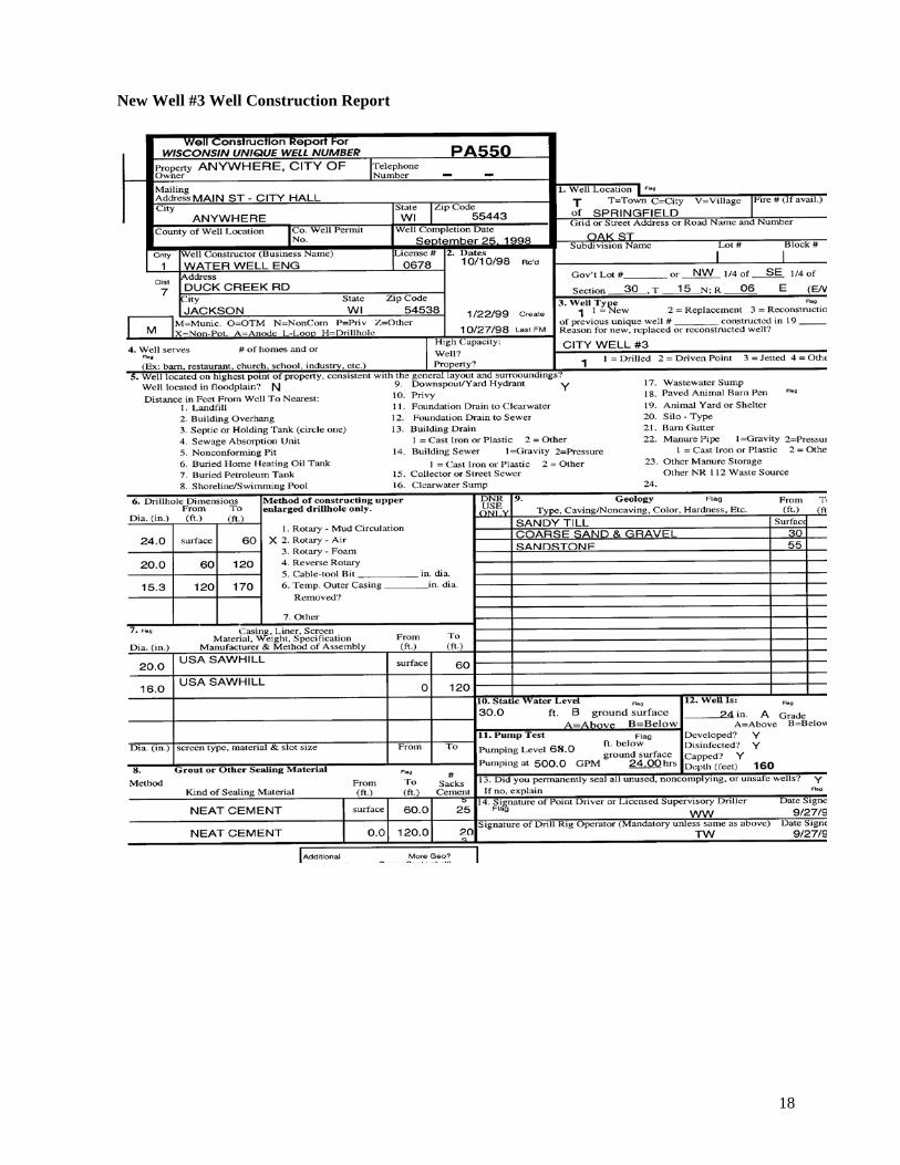
The zone of influence calculation requires that the transmissivity (T) of the aquifer be known. There are several methods for determining the transmissivity. All of the methods rely on a properly conducted pump test, preferably with observation wells. Once the data from the pump test has been gathered, T can be calculated by one of the following methods. 1) TGUESS PROGRAM Tguess is a program written by Ken Bradbury and E. R. Rothschild. The program uses basic information from a Well Construction Report (next page) or other pump test data to estimate the transmissivity of the aquifer being tested. The program code is available in the March-April 1985 issue of Groundwater. The compiled program is available from the International Ground Water Modeling Center in Golden, CO. Input parameters for well #3 are:
Well diameter 15.3 inches Depth to water, static 30 feet Depth to water, during pumping 68 feet Duration of the test 24 hours Pumping rate 500 gpm Thickness of the aquifer 100 feet Open interval of the well 50 feet Storage coefficient 0.1 Well loss coefficient 1 Output Specific Capacity = 13.15 Transmissivity = 4.66 x 10⁻² ft2/sec = 30120 gpd/ft Hydraulic Conductivity = 4.66 x 10⁻⁴ ft/sec = 40 ft/day 2) THEIS METHOD When good records are kept for the pump test and constant rates of pumping are used, a time drawdown graph of the test can be constructed. The time drawdown graph done on semilog paper can then be used to directly calculate the transmissivity. T = 264Q ∆s
Where: T = transmissivity in gpd/ft Q = pumping rate in gpm ∆s = slope of the time-drawdown graph over one log cycle Using the data from the pumping well (Table 1) and Figure 3:

17
Observation Well #2 Well Construction Report
18
New Well #3 Well Construction Report

19
WELL INFORMATION WATERWORKS: ___Anywhere, Wis PWS I.D.: ____77777777____________ WELL NUMBER: ____3_______ UNIQUE WELL NUMBER: ____PA550___________________ OPERATOR: ____Henry Darcy___________________ PHONE: ______715-111-111___________ WELL LOCATION: NW ¼ SE ¼, SECTION _30_, T_15_N, R_06_E STREET ADDRESS of WELL: ____101 Oak St.______________________________ IS WELL LOCATED IN A FLOOD PLAIN: __no___ WELL ADEQUATELY PROTECTED: __yes__ DATE CONSTRUCTED: _9/25/98____ WELL DRILLER: ____Water Well Enginerring____ WELLHEAD ELEVATION (MSL): ____760___________ DATUM: ____nad 27____________ GEOLOGIC DATA: FORMATIONS DEPTH FROM TO _____Sandy Till_________________________ _____Sand and gravel____________________ _____Sandstone______________________________ ______________________________________________
__0_ _30_ _55_ ____
_30_ _55_ _170 ____
CASING DATA DIAMETER
___20___ ___16___
_0__ _0__
__60_ _120_
SCREEN/ BOREHOLE
DIAMETER
___24___ ___20___ 15.3
__0_ _60_
_60_ _120_
GROUT DEPTH _____________ ORIGINAL CURRENT STATIC WATER LEVEL: __30__ _____ PUMPING WATER LEVEL: _68_ @ _500_ GPM _____ @ ____ GPM SPECIFIC CAPACITY: _____ GPM/FT _____ GPM/FT MEANS FOR MEASURING WATER LEVELS: ___________ AIRLINE LENGTH: ____________
WELL PUMP MAKE: __Byron Jackson______________ TYPE: _________Vertical Turbine__________ DESIGN CAPACITY: __600___ GPM @ _280_ FT. HD. SETTING: ______80 feet________ (top of the bowls) OPERATIONAL CAPACITY: __500__ GPM @ _______ FT. HD (well discharge pressure + pumping water level)
20
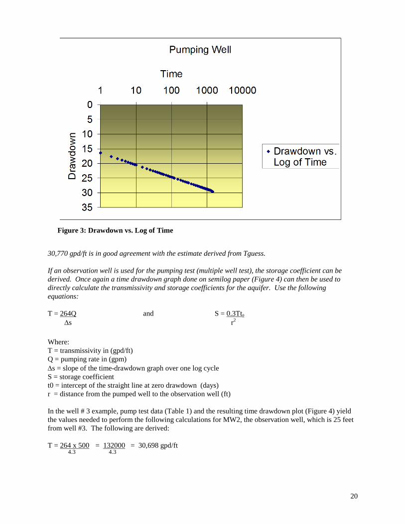
T = 264Q = 264 x 500 = 132000 = 30,770 gpd/ft
∆s 4.29 4.29 30,770 gpd/ft is in good agreement with the estimate derived from Tguess. If an observation well is used for the pumping test (multiple well test), the storage coefficient can be derived. Once again a time drawdown graph done on semilog paper (Figure 4) can then be used to directly calculate the transmissivity and storage coefficients for the aquifer. Use the following equations: T = 264Q and S = 0.3Tt0 ∆s r2
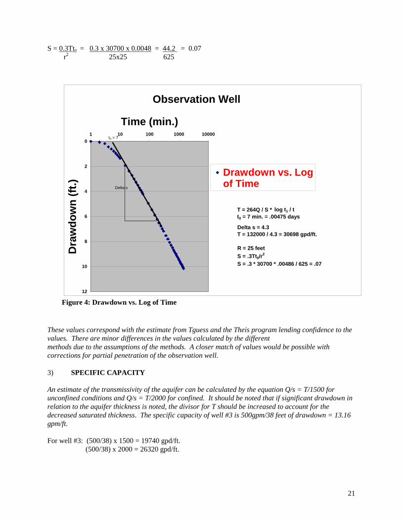
Where: T = transmissivity in (gpd/ft) Q = pumping rate in (gpm) ∆s = slope of the time-drawdown graph over one log cycle S = storage coefficient t0 = intercept of the straight line at zero drawdown (days) r = distance from the pumped well to the observation well (ft) In the well # 3 example, pump test data (Table 1) and the resulting time drawdown plot (Figure 4) yield the values needed to perform the following calculations for MW2, the observation well, which is 25 feet from well #3. The following are derived: T = 264 x 500 = 132000 = 30,698 gpd/ft
4.3 4.3
Figure 3
Figure 3: Drawdown vs. Log of Time
21
Observation Well
0
2
4
6
8
10
12
1 10 100 1000 10000
Time (min.)
Dra
wdo
wn
(ft.)
Drawdown vs. Logof Time
Delta s = 4.3T = 132000 / 4.3 = 30698 gpd/ft.
R = 25 feetS = .3Tt0/r
2
S = .3 * 30700 * .00486 / 625 = .07
T = 264Q / S *t0 = 7 min. = .00475 days
log t1 / t
t0 = 7
Delta s
Figure 4: Drawdown vs. Log of Time
S = 0.3Tt0 = 0.3 x 30700 x 0.0048 = 44.2 = 0.07 r2 25x25 625
These values correspond with the estimate from Tguess and the Theis program lending confidence to the values. There are minor differences in the values calculated by the different methods due to the assumptions of the methods. A closer match of values would be possible with corrections for partial penetration of the observation well. 3) SPECIFIC CAPACITY An estimate of the transmissivity of the aquifer can be calculated by the equation Q/s = T/1500 for unconfined conditions and Q/s = T/2000 for confined. It should be noted that if significant drawdown in relation to the aquifer thickness is noted, the divisor for T should be increased to account for the decreased saturated thickness. The specific capacity of well #3 is 500gpm/38 feet of drawdown = 13.16 gpm/ft. For well #3: (500/38) x 1500 = 19740 gpd/ft. (500/38) x 2000 = 26320 gpd/ft.

22
This range of values is lower than those calculated by the other methods because the multipliers are based on estimates for a well with a smaller radius and a slightly larger storage coefficient. Nevertheless, this method for estimating T can be useful when there is limited data available. Table 1 Pump Test Results
Pump test Recovery minutes Days Pumping
well #3
Observation well #2
minutes days pumping well
1 0.0006944 24.95 0 1 0.0006944 13.58 2 0.0013889 26.25 0.07 2 0.0013889 12.29 3 0.0020833 27 0.18 3 0.0020833 11.53 4 0.0027778 27.54 0.43 4 0.0027778 11.00 5 0.0034722 27.95 0.61 5 0.0034722 10.58 6 0.0041667 28.3 0.78 10 0.0069444 9.29 7 0.0048611 28.59 0.94 20 0.0138889 8.01 8 0.0055556 28.83 1.09 30 0.0208333 7.27 9 0.0062500 29.05 1.23 40 0.0277778 6.74
10 0.0069444 29.25 1.36 50 0.0347222 6.34 15 0.0104167 30.01 1.92 60 0.0416667 6.01 20 0.0138889 30.54 2.36 120 0.0833333 4.79 25 0.0173611 30.96 2.71 180 0.1250000 4.10 30 0.0208333 31.3 3.01 240 0.1666667 3.63 35 0.0243056 31.58 3.27 300 0.2083333 3.28 40 0.0277778 31.83 3.5 360 0.2500000 3.01 45 0.0312500 32.05 3.71 420 0.2916667 2.78 50 0.0347222 32.25 3.89 480 0.3333333 2.59 55 0.0381944 32.43 4.06 540 0.3750000 2.43 60 0.0416667 32.59 4.21 600 0.4166667 2.29 90 0.0625000 33.35 4.94 660 0.4583333 2.16
120 0.0833333 33.88 5.47 720 0.5000000 2.05 150 0.1041667 34.3 5.88 780 0.5416667 1.95 180 0.1250000 34.64 6.22 840 0.5833333 1.86 210 0.1458333 34.93 6.51 900 0.6250000 1.78 240 0.1666667 35.18 6.76 960 0.6666667 1.71 270 0.1875000 35.4 6.99 1020 0.7083333 1.64 300 0.2083333 35.59 7.18 1080 0.7500000 1.58 360 0.2500000 35.93 7.53 1140 0.7916667 1.53 420 0.2916667 36.22 7.81 1200 0.8333333 1.47 480 0.3333333 36.47 8.06 1260 0.8750000 1.42 540 0.3750000 36.69 8.29 1320 0.9166667 1.38 600 0.4166667 36.89 8.49 1380 0.9583333 1.33 660 0.4583333 37.07 8.69 1440 1.0000000 1.29 720 0.5000000 37.23 8.84 780 0.5416667 37.38 8.98 840 0.5833333 37.52 9.12 900 0.6250000 37.64 9.25 960 0.6666667 37.77 9.37
1020 0.7083333 37.88 9.49 1080 0.7500000 37.98 9.6 1140 0.7916667 38.09 9.71 1200 0.8333333 38.18 9.8 1260 0.8750000 38.27 9.89 1320 0.9166667 38.36 9.98 1380 0.9583333 38.44 10.05 1440 1.0000000 38.59 10.15
Zone Of Influence The 30 day zone of influence (ZOI) can then be calculated by computer program or by Theis methods.
23
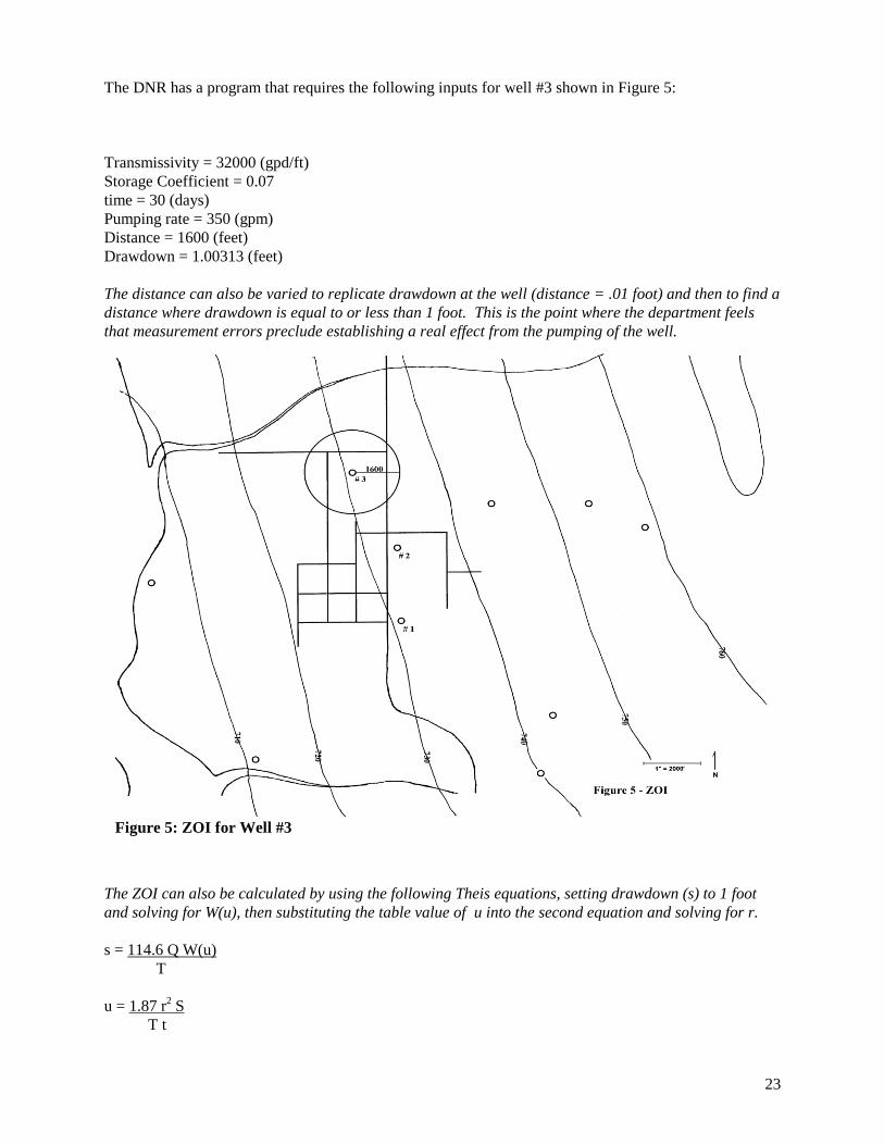
Figure 5: ZOI for Well #3
The DNR has a program that requires the following inputs for well #3 shown in Figure 5: Transmissivity = 32000 (gpd/ft) Storage Coefficient = 0.07 time = 30 (days) Pumping rate = 350 (gpm) Distance = 1600 (feet) Drawdown = 1.00313 (feet) The distance can also be varied to replicate drawdown at the well (distance = .01 foot) and then to find a distance where drawdown is equal to or less than 1 foot. This is the point where the department feels that measurement errors preclude establishing a real effect from the pumping of the well.
The ZOI can also be calculated by using the following Theis equations, setting drawdown (s) to 1 foot and solving for W(u), then substituting the table value of u into the second equation and solving for r. s = 114.6 Q W(u) T u = 1.87 r2 S T t
24
Where: T = transmissivity in (gpd/ft) Q = pumping rate in (gpm) s = drawdown (ft) S = storage coefficient t = time (days) r = distance from the pumped well to the observation point (ft) W(u) = s x T = 1’ x 30700 = 30700 = 0.7654
114.6 x Q 114.6 x 350 40110 u is then equal to 0.36 r2 = T x t x u = 30700 x 30 x 0.36 = 331560 = 2532926
S x 1.87 1.87 x .07 0.1309
r = 1592 feet
25
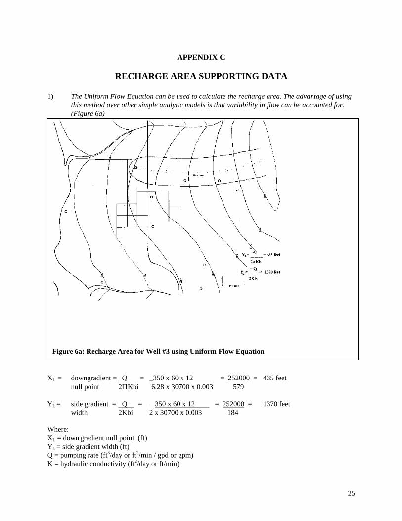
Figure 6a: Recharge Area for Well #3 using Uniform Flow Equation
APPENDIX C
RECHARGE AREA SUPPORTING DATA
1) The Uniform Flow Equation can be used to calculate the recharge area. The advantage of using this method over other simple analytic models is that variability in flow can be accounted for. (Figure 6a)
XL = downgradient = Q = _350 x 60 x 12 = 252000 = 435 feet null point 2ΠKbi 6.28 x 30700 x 0.003 579
YL = side gradient = Q = __350 x 60 x 12 = 252000 = 1370 feet width 2Kbi 2 x 30700 x 0.003 184
Where: XL = down gradient null point (ft) YL = side gradient width (ft) Q = pumping rate (ft3/day or ft2/min / gpd or gpm) K = hydraulic conductivity (ft2/day or ft/min)

26
b = aquifer thickness (ft) Kb = transmissivity (ft2/day or ft2/min / gpd/ft or gpm/ft) i = hydraulic gradient (ft/ft) 2) The recharge area for the well can also be determined by using models and running the model in
steady state. Using the RESSQC module of the US EPA WHPA codes the resulting area has a downgradient null point of 400 feet and a width of 1800 feet extending back to the groundwater divide 12000 feet to the east. (Figure 6b)
Figure 6b: Recharge Area for Well #3 using RESSQC
27
APPENDIX D
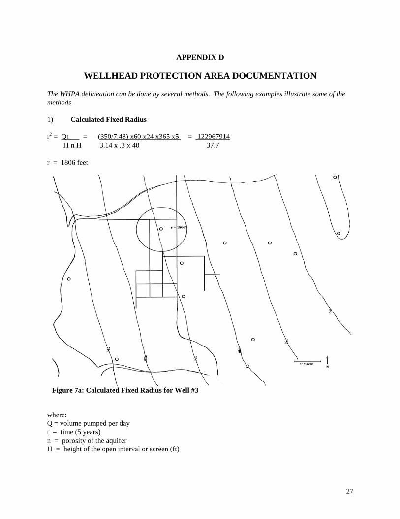
WELLHEAD PROTECTION AREA DOCUMENTATION The WHPA delineation can be done by several methods. The following examples illustrate some of the methods. 1) Calculated Fixed Radius r2 = Qt = (350/7.48) x60 x24 x365 x5 = 122967914 Π n H 3.14 x .3 x 40 37.7 r = 1806 feet
where: Q = volume pumped per day t = time (5 years) n = porosity of the aquifer H = height of the open interval or screen (ft)
Figure 7a: Calculated Fixed Radius for Well #3
28
Another volumetric calculation can be based on a two-dimensional static water balance analysis. This does require an estimate of the recharge rate for the area. r 2 = Qt/NΠ t + n Π H = 122967914/13.1 + 31.1 = 122967914/44.2 r = 1668 feet Where: r = Radius t = Time (5 years) N = Recharge (0.833 ft/d or yr) H = Open interval Q = Pumping rate (ft3/d or yr) n = Aquifer porosity When t is very large the solution represents the entire capture zone and the equation can be written as: r2 = Q/ NΠ = 33690/.007 r = 2194 feet 2) Uniform flow equation XL = Q = 350 x 60 x 12 = 252000 = 435 feet 2ΠKbi 6.28 x 30700 x 0.003 579
YL = Q = 350 x 60 x 12 = 252000 = 1370 feet 2Kbi 2 x 30700 x 0.003 184 Where:
XL = down gradient null point (ft) YL = side gradient width (ft) Q = pumping rate (gpd) K = hydraulic conductivity (ft/day) b = aquifer thickness (ft) Kb = transmissivity (gpd/ft) i = hydraulic gradient (ft/ft) A calculation of the 5 year time of travel (TOT) along a flow path can be done using the following equation. V = KI = 40 x .003 = 0.80 feet/day ne 0.15 Where: V = velocity (ft/d) K = hydraulic conductivity (ft/d) I = hydraulic gradient (ft/ft) ne = effective porosity 0.80 ft/day x 365 days x 5 years = 1460 feet. (Figure 7b) The five year time of travel along a flow path line defined by the uniform flow equation is about 1460 feet. This is a shorter distance than would be modeled by other methods because it does not take into account the increased gradient due to pumping. To be protective a safety factor should be added to this
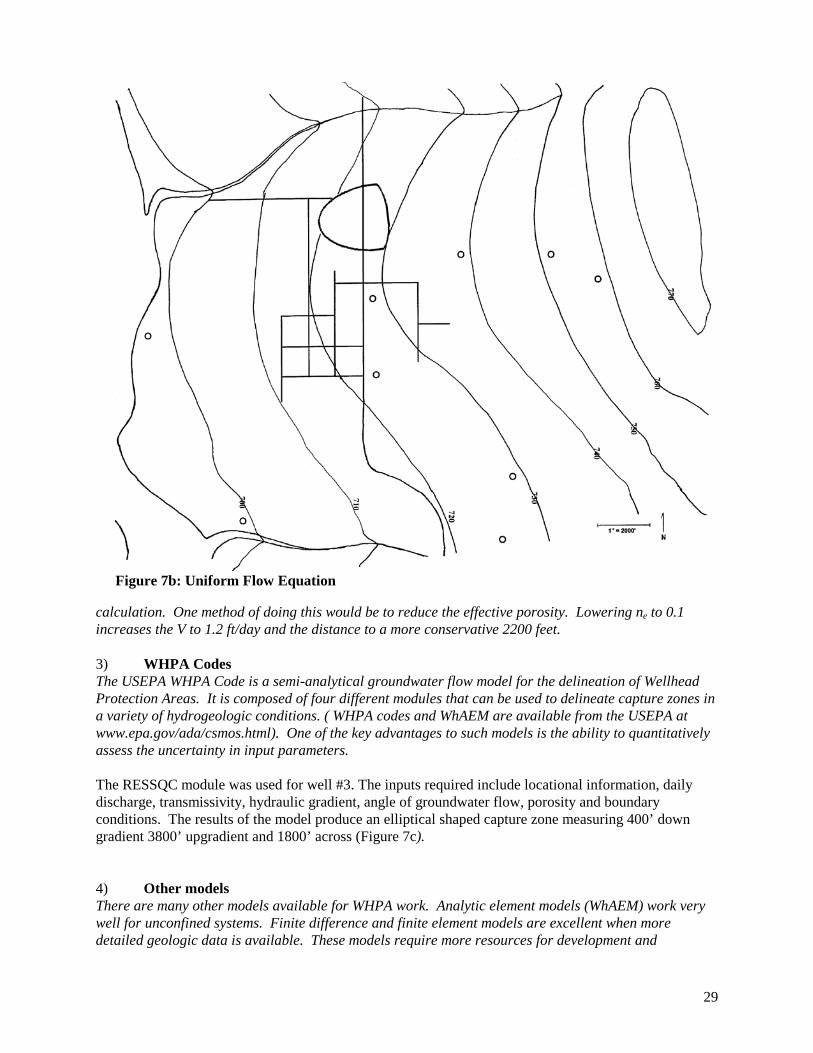
29
calculation. One method of doing this would be to reduce the effective porosity. Lowering ne to 0.1 increases the V to 1.2 ft/day and the distance to a more conservative 2200 feet. 3) WHPA Codes The USEPA WHPA Code is a semi-analytical groundwater flow model for the delineation of Wellhead Protection Areas. It is composed of four different modules that can be used to delineate capture zones in a variety of hydrogeologic conditions. ( WHPA codes and WhAEM are available from the USEPA at www.epa.gov/ada/csmos.html). One of the key advantages to such models is the ability to quantitatively assess the uncertainty in input parameters. The RESSQC module was used for well #3. The inputs required include locational information, daily discharge, transmissivity, hydraulic gradient, angle of groundwater flow, porosity and boundary conditions. The results of the model produce an elliptical shaped capture zone measuring 400’ down gradient 3800’ upgradient and 1800’ across (Figure 7c). 4) Other models There are many other models available for WHPA work. Analytic element models (WhAEM) work very well for unconfined systems. Finite difference and finite element models are excellent when more detailed geologic data is available. These models require more resources for development and
Figure 7b: Uniform Flow Equation

30
calibration, but provide the greatest amount of confidence in the predictive results. The choice of which model to use will depend on the geologic setting, data available and the experience of the modeler.
Figure 7c: 5 Yr. TOT Delineation for Well #3 using WHPA

31
APPENDIX E
POTENTIAL CONTAMINATION SOURCE SUPPORTING DATA
The following potential sources are located within ½ mile of well #3 and shown on Figure 8.
POTENTIAL
CONTAMINATION SOURCE
DISTANCE AND DIRECTION
OWNER / CONTACT
ADDRESS / PHONE
1 Storm sewer 150 feet northeast city/pw director City Hall 715-333-222
2 Sanitary sewer
500 feet west city/pw director City Hall 715-333-222
3 Residential fuel oil tank Contaminate sources cont.
250 feet north Mrs. Smith 111 Maple Lane 715-111-1111
Figure 8: Potential Contamination Sources
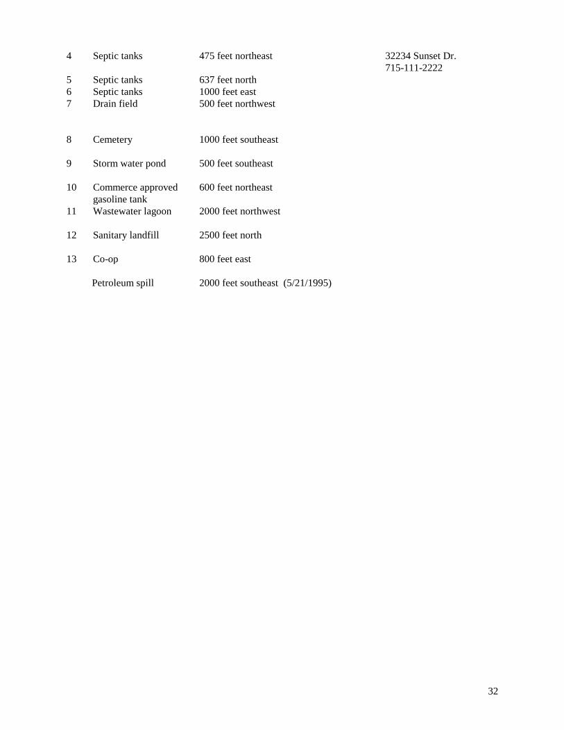
32
4 Septic tanks
475 feet northeast 32234 Sunset Dr. 715-111-2222
5 Septic tanks 637 feet north 6 Septic tanks 1000 feet east 7 Drain field
500 feet northwest
8 Cemetery
1000 feet southeast
9 Storm water pond
500 feet southeast
10 Commerce approved gasoline tank
600 feet northeast
11 Wastewater lagoon
2000 feet northwest
12 Sanitary landfill
2500 feet north
13 Co-op 800 feet east Petroleum spill 2000 feet southeast (5/21/1995)

33
APPENDIX F
EXAMPLE WELLHEAD PROTECTION ORDINANCE
The following wellhead protection (WHP) ordinance is a good example of a local zoning ordinance which has been adopted to control land uses within a WHP area and maintain separation distances. Most ordinances follow a structure similar to the following. Purpose and authority All ordinances have similar purpose and authority sections. The ordinance should contain specific statutory citations. Applicability Indicates where the ordinance applies. It may be a general description within the community boundaries or it may specify the legal description for the WHPA. It could reference a map. Definitions Each ordinance normally includes definitions, although the specific terms defined may differ. The definitions can be tailored to the needs of the community. The Department can assist with definitions if needed. Groundwater Protection Overlay District This section describes the area to be protected and how the area can be used. This section may reference a map, which is frequently attached to the ordinance. This section usually lists permitted and prohibited uses and may list conditional uses within the area to be protected. Often, the overlay district is subdivided into two or more zones where the permitted and prohibited uses may differ. Ideally, this section also lists the separation distances in NR 811 or at least references those separation distances. For some ordinances, this section also includes design standards for land uses within the overlay district. Exemptions and Waivers This section provides for exceptions to the uses listed in the previous section; this is for both existing facilities as well as proposed land uses. For new facilities, the ordinance may list conditional uses, in which case a procedure is normally laid out for reviewing conditional uses. It could also be called Other Permitted Uses. Either this section or a separate section usually contains requirements for existing facilities, which may not conform to the uses allowed in the WHPA. Some ordinances have more detailed requirements than others. This section could be called Non-conforming Uses or Requirements for Existing Facilities. Enforcement and Penalties This section describes how the ordinance will be enforced. It may lay out specifics or reference an existing municipal code. Severability Clause Most ordinances have a clause indicating that the entire ordinance is not invalid if a portion of it is determined to be invalid or unconstitutional. Effective Date Ordinances identify the effective date. Additional information

34
Other language is possible besides that included in the example. More example ordinances are available on the DNRs wellhead protection web site at www.dnr.state.wi.us/org/water/dwg/gw/whp.htm. For other example ordinances go to the U. S. Environmental Protection Agency Region 5 Electronic Compendium of Groundwater Protection Ordinances at http://www.epa.gov/r5water/ordcom/ Ordinances are available at this site in Adobe Acrobat (.PDF) format. For more information, contact the Bureau of Drinking Water and Groundwater, Wisconsin DNR, P. O. Box 7921, Madison, WI 53707. Phone: 608-266-0821

35
CHAPTER 29 WELLHEAD PROTECTION
29.01 Purpose and Authority 29.02 Application of Regulations 29.03 Definitions 29.04 Groundwater Technical Review Committee 29.05 Groundwater Protection Overlay District 29.06 Supremacy of This District 29.07 Zones 29.08 Groundwater Protection Overlay Districts Boundaries 29.09 Permitted Uses 29.10 Separation Distance Requirements 29.11 Prohibited Uses 29.12 Conditional Uses 29.13 Requirements for Existing Facilities Which May Cause or Threaten to Cause Environmental Pollution 29.14 Changing Technology 29.15 Enforcement and Penalty 29.16 Conflict, Interpretation and Severability

36
WELLHEAD PROTECTION ORDINANCE
29.01 PURPOSE AND AUTHORITY. (1) PURPOSE. The residents of the City of __________ depend exclusively on groundwater for a safe drinking water supply. Certain land use practices and activities can seriously threaten or degrade groundwater quality. The purpose of this Wellhead Protection Ordinance is to institute land use regulations and restrictions protecting the municipal water supply of the City of _______ and promote the public health, safety and general welfare of the residents. (2) AUTHORITY. Statutory authority of the City to enact these regulations was established by the Wisconsin Legislature in 1983, Wisconsin Act 410 (effective May 11, 1984), which specifically added groundwater protection, in §59.97(1) and §62.23(7)(c), Wis. Stats., to the statutory authorization for county and municipal planning and zoning to protect the public health, safety and welfare. In addition, under §62.23(7)(c), Wis. Stats., the City has the authority to enact this ordinance, effective in the incorporated areas of the City, to encourage the protection of groundwater resources. 29.02 APPLICATION OF REGULATIONS. The regulations specified in this Wellhead Protection Ordinance shall apply to the incorporated areas of ________ that lie within the recharge areas for municipal water supply wells as defined in section 29.05, and are in addition to the requirements in the underlying zoning district, if any. If there is a conflict between this ordinance and the zoning ordinance, the more restrictive provision shall apply. 29.03 DEFINITIONS.
(1) AQUIFER. A saturated, permeable geologic formation that contains and will yield significant quantities of water.
(2) CONE OF DEPRESSION. The area around a well, in which the water level has been lowered at least one-tenth of a foot by pumping of the well.
(3) FIVE-YEAR TIME OF TRAVEL. The 5-year time of travel is the recharge area upgradient of the cone of depression, the outer boundary of which it is determined or estimated that groundwater will take five years to reach a pumping well.
(4) MUNICIPAL WATER SUPPLY. The municipal water supply of the City of ________. (5) PERSON. Person means an individual, partnership, association, corporation,
municipality or state agency, or other legal entity. (6) RECHARGE AREA. The area which encompasses all areas or features that, by surface
infiltration of water that reaches the zone of saturation of an aquifer, supplies groundwater to a well. (7) THIRTY-DAY TIME OF TRAVEL. The 30-day time of travel is the recharge area
upgradient of a well, or its cone of depression, the outer boundary of which it is determined or estimated that groundwater will take thirty days to reach a pumping well.
(8) WELL FIELD. A piece of land used primarily for the purpose of locating wells to supply a municipal water system.
(9) ZONE OF SATURATION. The saturated zone is the area of unconsolidated, fractured or porous material that is saturated with water and constitutes groundwater.
29.04 GROUNDWATER TECHNICAL REVIEW COMMITTEE.
(1) The Groundwater Technical Review Committee shall consist of: (a) The City Planner. (b) The City Engineer/Director of Public Works. (c) The Superintendent/Manager of Public Utilities.

37
(d) The County Conservationist. (e) The City Inspector. (f) A local representative from the Department of Natural Resources with expertise in
groundwater or groundwater contamination issues, appointed by their Department and approved by the City Council.
(g) One member, who has at least one of the following qualifications: 1. Is a hydrogeologist, hydrologist or a professional engineer with a background in
groundwater; or 2. Is a certified groundwater professional.
(2) The purpose of the Groundwater Technical Review Committee is to provide objective and scientific technical review of requests for conditional use permits and make recommendations to the Plan Commission to grant or deny conditional use permits based upon the facts discovered in that review, to make recommendations on any and all conditions placed on a conditional use permit, and to give advice on matters concerning groundwater.
29.05 GROUNDWATER PROTECTION OVERLAY DISTRICT. A Groundwater Protection Overlay District may be created to institute land use regulations and restrictions within a defined area which contributes water directly to a municipal water supply and thus promotes public health, safety, and welfare. The district is intended to protect the groundwater recharge area for the existing or future municipal water supply from contamination. 29.06 SUPREMACY OF THIS DISTRICT. The regulations of an overlay district will apply in addition to all other regulations which occupy the same geographic area. The provisions of any zoning districts that underlay this overlay district will apply except when provisions of the Groundwater Protection Overlay District are more stringent. 29.07 ZONES. The Groundwater Protection Overlay District is divided into Zone 1 and Zone 2 as follows: (1) ZONE 1 OF GROUNDWATER PROTECTION OVERLAY DISTRICT. Zone 1 is the area of land which contributes water to the well in question, out to a 30-day time of travel to the well. Time of travel delineations must be based on accepted hydrogeological research as outlined in the State Wellhead Protection Program Plan for Public Water Utilities, Appendix 2 with Zone boundaries normalized to road centerlines, railways, surface water features, and the public land survey section lines, 1/2, 1/4, 1/8, or 1/16 section lines. (2) ZONE 2 OF THE GROUNDWATER PROTECTION OVERLAY DISTRICT. Zone 2 encompasses the area of land which contributes water to the well starting at the line which delineates the 30-day time of travel and ends at the line delineating the 5-year time of travel to the well. Time of travel delineations must be based on accepted hydrogeological research as outlined in the State Wellhead Protection Program Plan for Public Water Utilities, Appendix 2 with Zone boundaries normalized to road centerlines, railways, surface water features, and the public land survey section lines, 1/2, 1/4, 1/8, or 1/16 section lines. 29.08 GROUNDWATER PROTECTION OVERLAY DISTRICTS BOUNDARIES.
(1) The boundaries of the Groundwater Protection Overlay Districts shall be shown on the zoning map. The locations and boundaries of the zoning districts established by this ordinance are set forth on the City of ___________ Municipal Wellhead Protection Areas Map which is incorporated herein and hereby made a part of this ordinance. Said map, together with everything shown thereon and all amendments thereto, shall be as much a part of this ordinance as though fully set forth and described herein.
(2) Zone 1 for the well fields is delineated on the Wellhead Protection Area Map which is attached and made a part of this ordinance as follows:

38
(a) East Well Field Area: The area delineated on the map which lies within the E 1/2 of SE 1/4 in Section __ and the SW 1/4 of Section__; all in Township __ North, Range __ West. (b) West Well Field Area: The area delineated on the map which lies within the SW 1/4 of Section__, all in Township __ North, Range __ West. (3) Zone 2 for the well fields is delineated on the Wellhead Protection Area Map as follows: (a) East Well Field Area: The SE 1/4 of NE 1/4, E 1/2 of SE 1/4 which lies east of the Chicago & Northwestern Railroad right of way, all in Section__; the W 1/2 of NE 1/4, SE 1/4 of NE 1/4, NE 1/4, S 1/2 of Section__; the S 1/2 of NE 1/4, W 1/2 of SW 1/4 of Section __ and lying west of Lake________; the E 1/2 of NE 1/4, E 1/2 of SE 1/4 which lies east of the Union Pacific Railroad right of way and south of Wisconsin Highway__, all in Section__; the N 1/2, SW 1/4 of Section __ and lying north of the ______ River; the NW 1/4 of NW 1/4 of Section __ and lying west of Lake______, all in Township __ North, Range __West, as shown on the attached map. (b) West Well Field Area: All of Section __ which lies north-westerly of Wisconsin State Highway__; the NW 1/4 of Section __ which lies north of the _____ River and all of Section __ which lies south of the _______ River, the S 1/2 of SW 1/4 of Section__; all in Township __ North, Range __ West, as shown on the attached map. The S 1/2 of SW 1/4 of Section__; the NW 1/4 of Section __ which lies north-westerly of Wisconsin State Highway __ and County Road __; all in Township __ North, Range __ West, as shown on the attached map.
29.09 PERMITTED USES.
(1) The following permitted uses in Zone 1 are subject to the separation distance requirements, section 29.10 and prohibited uses, section 29.11:
(a) Public and private parks, playgrounds and beaches, provided there are no on-site wastewater disposal systems or holding tanks.
(b) Wildlife and natural and woodland areas. (c) Biking, hiking, skiing, nature, equestrian and fitness trails. (d) Residential which is municipally sewered. (e) Routine tillage, planting, and field management operations in support of agricultural crop
production, where nutrients from legume, manure, and commercial sources are accounted for and credited toward crop nutrient need. The combination of all nutrient sources applied or available on individual fields may not exceed University of Wisconsin soil test recommendations for that field.
(2) The following permitted uses in Zone 2 are subject to the separation distance requirements, section 29.10 and prohibited uses, section 29.11:
(a) All of the uses permitted in Zone 1. (b) Single-family residences on a minimum lot of 20,000 square feet with a private on-site
sewage treatment system receiving less than 8,000 gallons per day, which meets the County and State health standards for the effluent, and is in conformance with SPS 383, Wis. Adm. Code.
(c) Commercial establishments which are municipally sewered. (d) Industrial establishments which are municipally sewered. (e) Residential use of above ground LP gas tanks for heating, not to exceed 1,000 gallons.
29.10 SEPARATION DISTANCE REQUIREMENTS. (1) The following separation distances as specified in NR 811.12(5)(d), Wis. Adm. Code,
shall be maintained:

39
(a) Fifty feet between a public water supply well and a stormwater sewer main or any sanitary sewer main constructed of water main materials and joints which is pressure tested in place to meet current AWWA 600 specifications.
(b) Two hundred feet between a public water supply well and any sanitary sewer main not meeting the above specifications, any sanitary sewer lift station or single-family residential fuel oil tank.
(c) Four hundred feet between a public water supply well and a septic system receiving less than 8,000 gallons per day, or a stormwater detention, retention, infiltration or drainage basin. 29.11 PROHIBITED USES.
(1) The following uses are prohibited in Zones 1 and 2: (a) Buried hydrocarbon, petroleum or hazardous chemical storage tanks. (Hazardous
chemicals are identified by OSHA criteria under 40CFR Part 370.) (b) Cemeteries. (c) Chemical manufacturers (Standard Industrial Classification Major Group 28). (d) Coal storage. (e) Dry cleaners. (f) Industrial lagoons and pits. (g) Landfills and any other solid waste facility, except post-consumer recycling. (h) Manure and animal waste storage except animal waste storage facilities regulated by the
County. (i) Nonmetallic earthen materials extraction or sand and gravel pits. (j) Pesticide and fertilizer dealer, transfer or storage. (k) Railroad yards and maintenance stations. (l) Rendering plants and slaughterhouses. (m) Salt or deicing material storage. (n) Salvage or junk yards. (o) Septage or sludge spreading, storage or treatment. (p) Septage, wastewater, or sewage lagoons. (q) Private on-site wastewater treatment systems or holding tanks receiving 8,000 gallons
per day or more. (r) Stockyards and feedlots. (s) Stormwater infiltration basins without pre treatment, including vegetative filtration
and/or temporary detention. (t) Motor vehicular services, including filling and service stations, repair, renovation and
body working. (u) Wood preserving operations. (2) In Zone 1, the conditional uses of section 29.12(2) are prohibited.
29.12 CONDITIONAL USES.
(1) Any person may request a conditional use permit for certain uses, activities and structures within Zone 2 of the Groundwater Protection Overlay District not prohibited in section 29.11.
(2) The uses, activities, and structures that may be conditionally allowed within Zone 2 are: (a) Jewelry plating and metal plating. (b) Machine or metal working shops. (c) Commercial establishments utilizing a private on-site wastewater treatment system
receiving less than 8,000 gallons per day, which is in conformance with SPS 383, Wis. Adm. Code. (d) Research labs, universities and hospitals. (e) Exposed hydrocarbon, petroleum or hazardous chemical storage tanks. (Hazardous
chemicals are identified by OSHA criteria under 40CFR Part 370.) This shall not apply to residential LP gas tanks which are permitted under section 29.09(2)(e).
40
(f) Storage or processing of extremely hazardous substances, radioactive materials or substances listed in Table 1, NR 140, Wis. Adm. Code (Extremely hazardous substances are identified by SARA/EPCRA criteria under 40 CFR Parts 302 and 355.)
(3) All requests for a conditional use permit shall be submitted in writing to the City Inspector, and shall include:
(a) A site plan map with all building and structure footprints, driveways, sidewalks, parking lots, stormwater management structures, groundwater monitoring wells, and 2-foot ground elevation contours.
(b) A business plan and/or other documentation which describes in detail the use, activities, and structures proposed.
(c) An environmental assessment report prepared by a licensed environmental engineer which details the risk to, and potential impact of, the proposed use, activities, and structures on groundwater quality.
(d) An operational safety plan, which details the operational procedures for material processes and containment, best management practices, stormwater runoff management, and groundwater monitoring.
(e) A contingency plan which addresses in detail the actions tat will be taken should a contamination event caused by the proposed use, activities, or structures occur.
(4) The person making the request shall reimburse the City for consultant fees and technical review committee expenses associated with this review at the invoiced amount, plus administrative costs.
(5) All conditional use permits granted shall be subject to conditions that will include environmental and safety monitoring determined necessary to afford adequate protection of the public water supply. These conditions shall include, but not be limited to:
(a) Provide current copies of all federal, state and local facility operation approval or certificates and on-going environmental monitoring results to the City.
(b) Establish environmental or safety structures/monitoring to include an operational safety plan, material processes and containment, operations monitoring, best management practices, stormwater runoff management, and groundwater monitoring.
(c) Replace equipment or expand in a manner that improves the environmental and safety technologies being utilized.
(d) Prepare, file and maintain a current contingency plan which details the response to any emergency which occurs at the facility, including notifying municipal, county and state officials. Provide a current copy to the City.
(e) The Plan Commission shall decide upon a request for a conditional use permit only after full consideration of the recommendations made by the Groundwater Technical Review Committee. Any conditions above and beyond those specified in Conditional Uses, subsection (5) herein, that are recommended by the Groundwater Technical Review Committee may be applied to the granting of the conditional use permit.
29.13 REQUIREMENTS FOR EXISTING FACILITIES WHICH MAY CAUSE OR THREATEN TO CAUSE ENVIRONMENTAL POLLUTION.
(1) Existing facilities within the Groundwater Protection Overlay District at the time of enactment of such district which may cause or threaten to cause environmental pollution include, but are not limited to, the Wisconsin Department of National Resources draft or current list of "Inventory of Sites or Facilities Which May Cause or Threaten to Cause Environmental Pollution", Wisconsin Department of Industry, Labor and Human Relations' list of underground storage tanks, list of facilities with hazardous, solid waste permits, and all other facilities which are considered a prohibited use in prohibited uses, section 29.11, or a conditional use in conditional uses, section 29.12, all of which are incorporated herein as if fully set forth.
41
(a) Such facilities as above which exist within the district at the time of enactment of a district shall provide copies of all current, revised or new federal, state and local facility operation approvals, permits or certificates; operational safety plans; and on-going environmental monitoring results to the City.
(b) Such facilities as above which exist within the district at the time of enactment of a district shall have the responsibility of devising, filing and maintaining, with the City, a current contingency plan which details how they intend to respond to any emergency which may cause or threaten to cause environmental pollution that occurs at their facility, including notifying municipal, county and state officials.
(c) Such facilities as above cannot engage in or employ a use, activity, or structure listed in prohibited uses, section 29.11, or in conditional uses, section 29.12, which they did not engage in or employ at the time of enactment of a district, and can only expand, replace or rebuild those present uses, activities, equipment, or structures on the site or property of record associated with the facility at the time of enactment of a district, and in a manner that improves the environmental and safety technologies already being utilized. No existing use, activity, or structure listed as a prohibited use or conditional use shall be expanded, replaced, or rebuilt unless a conditional use permit is granted for such expansion, replacement, or rebuilding. This section does not apply to normal maintenance or minor repairs.
29.14 CHANGING TECHNOLOGY.
(1) The uses prohibited by this district are prohibited based upon the combined pollution experience of many individual uses, and the technology generally employed by a particular use considered to be of a high risk for pollution to the groundwater resource. As the technology of other uses change to low or non-risk materials or methods, upon petition from such use, after conferring with the Groundwater Technical Review Committee or other expert opinion, and after appropriate public notice and hearing, the City through appropriate procedures and actions to change these provisions of the Municipal Code may remove from the designated prohibited uses such uses as are demonstrated convincingly that they no longer pose a groundwater pollution hazard.
(2) In dealing with uses which attempt to become permissible, under the terms of this district, by continuing to utilize pollutant materials but altering their processing, storage and handling, it is not the intention to accept alternate or reduced hazards as the basis for making a use permissible. It is the intention to continue a prohibition on such uses until the technology of the use removes reliance upon the pollutant materials or processes deemed to be a groundwater hazard. 29.15 ENFORCEMENT AND PENALTY.
(1) PENALTY. Any person who violates, neglects or refuses to comply with any of the provisions of this ordinance shall be subject to a penalty as provided in Chapter 25 of this Municipal Code.
(2) INJUNCTION. The City may, in addition to any other remedy, seek injunction or restraining order against the party alleged to have violated the provisions herein, the cost of which shall be charged to the defendant in such action.
(3) CLEANUP COSTS. As a substitute for, and in addition to any other action, the City may commence legal action against both the person who releases the contaminants and the owner of the facility whereupon the contaminants were released to recover the costs, together with the costs of prosecution. Any person who causes the release of any contaminants which may endanger or contaminate the municipal water supply system associated with a Ground Water Protection Overlay District shall immediately cease such discharge and immediately initiate clean up satisfactory to the City and the other state and federal regulatory agencies. The person who releases such contaminants and the person who owns the facility whereon the contaminants have been released shall be jointly and severally responsible for the cost of cleanup, consultant, or other contractor fees, including all administrative costs for oversight, review and documentation, including the City employees, equipment, and mileage.

42
29.16 CONFLICT, INTERPRETATION AND SEVERABILITY. (1) CONFLICT AND INTERPRETATION OF PROVISIONS. If the provisions of the
different chapters of this Code conflict with or contravene each other, the provisions of each chapter shall prevail as to all matters and questions arising out of the subject matter of such chapter. In their interpretation and application, the provisions of this ordinance shall be held to be the minimum and are not deemed a limitation or repeal of any other power granted by Wisconsin Statutes. Where any terms or requirements of this ordinance may be inconsistent or conflicting, the most restrictive requirements or interpretations shall apply.
(2) SEVERABILITY OF CODE PROVISIONS. If any section, subsection, sentence, clause or phrase of the Code is for any reason held to be invalid or unconstitutional by reason of any decision of any court of competent jurisdiction, such decision shall not affect the validity of any other section, subsection, sentence, clause or phrase or portion thereof. The City Council hereby declares that they would have passed this Code and each section, subsection, sentence, clause, phrase or portion thereof irrespective of the fact that any one or more sections, subsections, sentences, clauses, phrases or portions may be declared invalid or unconstitutional.

43
APPENDIX G
(MODEL LOCAL WELL REGUALTION ORDINANCE)
WELL ABANDONMENT and WELL OPERATl0N PERMIT ORDINANCE WHEREAS, s. NR 810.16, Wisconsin Administrative Code, directs suppliers of water for municipal water systems, and communities served by municipal water systems, to implement a local well regulation program requiring proper abandonment of unused, unsafe or noncomplying wells located on premises served by the municipal water system, and to provide permits for retention of safe, code-complying wells by local ordinance or water utility rule, in order to prevent all unused, unsafe, and noncomplying wells from becoming safety hazards or channels for contamination of aquifers, and to prevent illegal cross-connections with the municipal system.
NOW THEREFORE, the __________________________________
of the (City, Village or Town) of ________________________________ , _________________________
County, Wisconsin, does ordain as follows:
SECTION 1: PURPOSE To protect public health, safety and welfare and to prevent contamination of water supplies by assuring that unused, unsafe or noncomplying wells or wells which may act as conduits for contamination of groundwater or wells which may be illegally cross-connected to the municipal water system, are properly maintained or properly filled-and-sealed.
SECTION 2: APPLICABILITY This Ordinance applies to all wells located on premises served by the _________________________ municipal water system. Communities outside the jurisdiction of a supplying municipal system are also required by code, contract agreement, or utility rule to adopt and enforce equivalent ordinances within their jurisdictions for purpose stated in Section 1 above.
SECTION 3: DEFINITIONS A. “Municipal water system” means a community water system owned by a city, village, county, town,
town sanitary district, utility district, public inland lake and rehabilitation district, municipal water district or a federal, state, county, or municipal owned institution for congregate care or correction, or a privately owned water utility serving the foregoing;
B. “Communities served” means any jurisdiction having customers supplied by a municipal water
system as retail or wholesale customers, including those outside the jurisdiction of the supplying system;
C. “Noncomplying” means a well or pump installation which does not comply with s. NR 812.42,
Wisconsin Administrative Code, Standards for Existing Installations, and which has not been granted a variance pursuant to s. NR 812.43, Wisconsin Administrative Code;
D. “Pump installation” means the pump and related equipment used for withdrawing water from a well,
including the discharge piping, the underground connections, pitless adapters, pressure tanks, pits, sampling faucets and well seals or caps;
44
D. “Served by” means any property having a water supply pipe extending onto it which is connected to
the municipal water system; E. “Unsafe” well or pump installation means one which produces water which is bacteriologically
contaminated or contaminated with other substances exceeding the drinking water standards of chs. NR 140 or 809, Wisconsin Administrative Code, or for which a Health Advisory has been issued by the Department of Natural Resources.
F. “Unused” well means one which does not have a functional pumping system or other complying
means of withdrawing water. G. “Well” means a drillhole or other excavation or opening deeper than it is wide that extends more than
10 feet below the ground surface constructed for the purpose of obtaining groundwater. H. “Well abandonment” means the proper filling-and-sealing or decommissioning of a well according to
the provisions of s. NR 812.26, Wisconsin Administrative Code.
SECTION 4: WELL ABANDONMENT REQUIRED All wells on premises served by the municipal water system shall be properly filled-and-sealed in accordance with Section 6 of this ordinance by ( date) or not later than ( days) [90 days to 1 year] from the date of connection to the municipal water system, or discovery or construction of a well, unless a valid well operation permit has been issued to the well owner by (municipality ) under terms of Section 5 of this ordinance.
SECTION 5: WELL OPERATION PERMIT Owners of wells on premises served by the municipal water system shall make application for a well operation permit for each well no later than (days) [90 days to 1 year] after connection to the municipal water system or date of discovery or construction of a well. The (municipality) shall grant a permit to a well owner to operate a well for a period not to exceed 5 years providing all conditions of this section are met. A well operation permit may be renewed by submitting an application verifying that the conditions of this section are met. The (municipality) or its agent, may conduct inspections and water quality tests or require inspections and water quality tests to be conducted at the applicant’s expense to obtain or verify information necessary for consideration of a permit application or renewal. Permit applications and renewals shall be made on forms provided by the Clerk. [(optional) All initial and renewal applications must be accompanied by a fee of (__ )].
The following conditions must be met for issuance or renewal of a well operation permit:
(1) The well and pump installation shall comply with the Standards for Existing Installations described in s. NR 812.42, Wisconsin Administrative Code, or repaired to comply with current standards. Compliance shall be verified by inspection for initial issuance of a permit and every 10 years thereafter. Inspections shall be conducted by a Wisconsin licensed well driller or pump installer and documented on inspection report form DNR #3300-221, to be submitted to the Clerk.
(2) The well and pump shall have a history of producing safe water evidenced by a certified lab report
for at least 1 coliform bacteria sample collected within prior 30 days, and submitted to the Clerk. In areas where the Department of Natural Resources (DNR) has determined that groundwater aquifers are contaminated with substances other than bacteria, additional chemical tests may be required to document the safety of the water.
45
(3) There shall be no cross-connections or interconnection between the well’s pump installation or
distribution piping and the municipal water system unless approved by the utility and DNR. (4) The water from the private well shall not discharge into a drain leading directly to a public sewer
utility unless properly metered and authorized by the sewer utility.
(5) The private well shall have a functional pumping system or other complying means of withdrawing water.
(6) The proposed use of the private well shall be justified as reasonable in addition to water provided by
the municipal water system.
SECTION 6: WELL FILLING-AND-SEALING PROCEDURES (1) All wells abandoned under the jurisdiction of this ordinance shall be filled-and-sealed according to
the procedures of s. NR 812.26, Wisconsin Administrative Code. (2) All well filling-and-sealing under jurisdiction of this ordinance shall be performed by, or under the
supervision of, a Certified Water System Operator employed by _(city, village, town where well is located)_ or by a Wisconsin licensed Well Driller or Pump Installer, per s. 280.30 Wisconsin Statutes.
(3) The owner of the well, or the owner’s agent, [(optional) may be required to obtain a well
abandonment permit prior to any well abandonment and] shall notify the clerk at least 48 hours in advance of any well abandonment activities. The abandonment of the well may be observed or verified by personnel of the municipal system.
(4) A well filling-and-sealing report form DNR#3300-005, supplied by the Department of Natural
Resources, shall be submitted by the well owner to the Clerk and to the Department of Natural Resources within 30 days of the completion of the well abandonment.
SECTION 7: PENALTIES Any well owner violating any provision of this ordinance shall upon conviction be punished by forfeiture of not less than ________ nor more than ____________ and the cost of prosecution. Each day of violation is a separate offense. If any person fails to comply with this ordinance for more than 30 days after receiving written notice of the violation, the municipality may impose a penalty and cause the well abandonment to be performed and the expense to be assessed as a special tax against the property.
46
APPENDIX H
EXAMPLE SPRINKLING BAN
In order to conserve water and to reduce the need for construction of additional wells, the water utility is requesting that customers participate in a voluntary yard-watering ban. During the summer, yard watering significantly increases the amount of water used each day. By reducing the amount of water used for sprinkling the water utility can delay the construction of additional wells that would ordinarily be needed to meet the high summer water demands. The benefit to the consumer is lower water rates in the long run, as money would not be needed to construct the additional wells and facilities. Therefore we are requesting that customers voluntarily restrict their yard watering to the following:
- Owners of houses on the even sides of street may water their yards on even days of the week. - Owners of houses on the odd sides of streets may water on the odd days of the week.
In order to realize the full benefit of reduced yard watering, we are also requesting that you try to restrict your watering to between the hours of 8:00 p.m. and 8:00 a.m. Water Superintendent City Water Utility

47
ATTACHMENT 1
WELLHEAD PROTECTION CONTACTS 1. DNR New Well (Regulatory) Wellhead Protection Coordinator Lee Boushon Public Water System Section
P. O. Box 7921 Madison, WI 53707-7921
(608) 266-0857 email: [email protected] 2. DNR Voluntary Wellhead Protection Coordinator Groundwater Section
P. O. Box 7921 Madison, WI 53707-7921 (608) 266-0821 3. The Wisconsin Geological and Natural History Survey (WGNHS) can provide information on what
type of geological and hydrogeological data are available for your area. For a list of WGNHS publications write or call:
Wisconsin Geological and Natural History Survey 3817 Mineral Point Road Madison, WI 53705 (608) 262-1705 web site: http://www.uwex.edu/wgnhs/ 4. The Central Wisconsin Groundwater Center is a clearinghouse for information on groundwater issues
in central Wisconsin. Central Wisconsin Groundwater Center
College of Natural Resources, room 224 University of Wisconsin - Stevens Point Stevens Point, WI 54481 (715) 346-4270 web site: http://www.uwsp.edu/groundwater/
5. The Wisconsin Rural Water Association (WRWA) has been providing technical assistance to rural communities (with water supplies that serve 10,000 people or less) that are trying to establish WHP programs.
Wisconsin Rural Water Association 350 Water Way Plover, WI 54467 (715) 344-7778 web site: http://wrwa.org/ 6. Your county University of Wisconsin - Extension office can provide general information on wellhead
protection. Look for the address and phone number in the telephone book under the county listings.

48
ATTACHMENT 2
GROUNDWATER PROTECTION TOOLS (adapted from Urban Institute, 1994)
Land Use Wellhead Protection Ordinances Time of travel delineations Overlay methods Exclusive use zones Property Purchase Capital or bond fund programs Easements Restrictive covenants Deed Restrictions Leasing of Land Recharge area acquisition Zoning Ordinances Subdivision Regulations Minimum Lot Sizes Slope controls, drainage maintenance Site Plan Review Environmental reviews Permit renewal Design Standards Building codes Setback requirements Performance standards Education General School Customers Focused Best Management Practices Assist major sources with management/ pollution prevention Conservation Distribution of low flow devices Retrofitting Water loss control Emergency use ordinances Sprinkling bans Contingency/Emergency Response Interagency / intergovernmental plans Household Hazardous waste collection (Clean Sweep) Include in fire and safety inspections Spill response capabilities
49
Other Groundwater monitoring Monitoring wells at critical sites Landfills Waste water treatment plants Known release sites Regular inspections Monitoring for pathogens, bacterial and viral Self monitoring of potential sources Policy and planning Source controls Use existing rule and regulations to control potential sources Discharge permits Pesticide management zones

50
ATTACHMENT 3
ANNOTATED BIBLIOGRAPHY OF WELLHEAD PROTECTION PUBLICATIONS
AND RELATED MATERIALS The following bibliography is divided into categories to make it easier to find information on a particular component of wellhead protection. General Wellhead Protection References Born, Steve, Douglas Yanggen and Alexander Zaporozec, 1987, A Guide to Groundwater Quality Planning and Management for Local Governments, Wisconsin Geological and Natural History Survey (WGNHS) Special Report 9, 91 p. This publication discusses in some detail the individual steps in the WHP process. The discussion on regulatory and nonregulatory tools is particularly noteworthy. Osborne, Tom, Jenifer Sorensen, Mark Knaack, David Mechenich and Michael Travis, 1989, Designs for Wellhead Protection in Central Wisconsin - Case Studies in the Town of Weston and City of Wisconsin Rapids, Central Wisconsin Groundwater Center, 95 p. plus appendix. Available from Central Wisconsin Groundwater Center (715-346-4270). This document starts with some basics about WHP, then discusses WHP area delineation, time of travel calculations, potential contaminant source inventory, and designing groundwater protection strategies. U. S. Environmental Protection Agency (EPA), 1991, Protecting Local Groundwater Supplies Through Wellhead Protection, EPA 570/9-91-007, 18 p. This is intended to be used by city or town officials, water supply managers or interested citizens. It contains a five-step process to help delineate, inventory and manage a local WHP area. U. S EPA, 1993, Wellhead Protection: A Guide for Small Communities - Seminar Publication, EPA/625/R-93-002, 144 p. This publication discusses groundwater fundamentals, sources of contamination, the 5-step WHP process; provides examples, including Cottage Grove; and provides resources for additional information. Wisconsin Department of Natural Resources (WDNR), 1993, Wellhead Protection Program Plan for Public Water Supplies, 29 p. plus appendices. This describes how Wisconsin will implement its WHP program. The program plan was approved by the U. S. Environmental Protection Agency in 1993. This document is downloadable (except appendices) at the Department’s Groundwater Section Web site (see below). U. S. Geological Survey (USGS), 1995, Groundwater Flow and Quality in Wisconsin’s Shallow Aquifer System, USGS Water Resources Investigations Report 90-4171, 42 p. This report provides an overview of groundwater movement and quality in the shallow aquifers of Wisconsin. The deeper aquifers are described to the extent that they affect or are affected by the shallow aquifers. Available from USGS Madison office. Wellhead Protection Delineation

51
Born, Steve, Douglas Yanggen, Allan Czecholinski, Raymond Tierney, and Ronald Hennings, 1988, Wellhead-Protection Districts in Wisconsin: An Analysis and Test Applications, WGNHS Special Report 10, 75 p. Reviews methods for delineating WHP districts and serves as a guide for hiring private consultants. Bradbury, K. R. and Rothchild, E. R., 1985, A Computerized Technique for Estimating the Hydraulic Conductivity of Aquifers from Specific Capacity Data, Groundwater vol. 23, no. 2, pp. 240-246. Driscoll, F. G., 1986, Groundwater and Wells, Johnson Filtration Systems, 1089 p. This is an excellent reference book on water supply wells. It contains a useful discussion of pump tests. U. S. EPA, 1991, Wellhead Protection Strategies for Confined Aquifer Settings, EPA 570/9-91-008, 168 p. This report discusses approaches to determine if an area is confined and what delineation methods are appropriate. Two examples are provided. U. S. EPA, 1991, Delineation of Wellhead Protection Areas in Fractured Rocks, EPA 570/9-91-009, 144 p. Written by Ken Bradbury, Maureen Muldoon and Alex Zaporozec. This report discusses two case studies from Wisconsin and discusses the options for WHP delineation in fractured rocks. U. S. EPA, 1994, Groundwater and Wellhead Protection - A Handbook, EPA/625/R-94/001, 269 p. Much of the book discusses methods for WHP area delineation. There is also guidance on developing a WHP plan, including a contaminant source inventory and management options, plus several case studies. U. S. EPA, 1998, Literature review of Methods for Delineating Wellhead Protection Areas, EPA 816-R-98-021, 34 p. This document presents the results of a bibliographic search for publications dealing with technical aspects of wellhead protection. The literature summaries are grouped by topic. WDNR, 1992, Determining Wellhead Protection Boundaries - An Introduction, PUBL-WR-313-92, 24 p. Explains the basics of the water cycle and groundwater flow and compares six methods of delineating WHP areas, including costs. Contaminant Source Inventory Cross, Brad L., and David P. Terry, 1991, A Groundwater Protection Strategy: The City of El Paso, Texas Water Commission Report 91-01, 154 p. Madarchik, Lillian Smith, 1992, How-to Manual for Groundwater Protection Projects: Volunteers and the Environment, El Paso (Texas) Retired Senior Volunteer Program (RSVP) in cooperation with the National Association of RSVP Directors, Inc., 26 pages plus appendices. Available from the WDNR or Winifred Dowling, El Paso RSVP Office (915-541-4375). WDNR, 1999, A Guide for Conducting Potential Contaminant Source Inventories for Wellhead Protection, PUBL DG-052 99, 38 p. This document provides communities step-by-step instructions for conducting an inventory of potential sources of contamination as part of a wellhead protection program. Wisconsin Groundwater Coordination Council, 1998, Directory of Groundwater Databases, 38 p. This directory provides a listing of groundwater-related databases, in both computer and paper formats, and a contact person to call for that information. Available from the WDNR. This document is downloadable at the Department’s Groundwater Section Web site (see below).
52
U.S.EPA, 1991, Guide for Conducting Contaminant Source Inventories for Public Drinking Water Supplies, 570/9-91-014, 53 p. +Appendices. Includes discussion of contaminant sources, use of existing data, options for gathering information and the importance of managing the data collected. Several case studies are also included. Wellhead Protection Management Born, Steve, Douglas Yanggen and Alexander Zaporozec, 1987, A Guide to Groundwater Quality Planning and Management for Local Governments, WGNHS Special Report 9, 91 p. This publication discusses in some detail the individual steps in the WHP process, especially regulatory and nonregulatory management tools. Horsley, S. and J. Witten, 1995, A Guide to Wellhead Protection, American Planning Association, Planning Advisory Service Report 457/458, 102 p. This publication describes groundwater fundamentals, groundwater contamination sources, management and financial strategies for WHP, and examples WHP ordinance language. Available from APA publications office, 122 S. Michigan Ave., Chicago, IL 60603-6107. Urban Institute, 1994, “Groundwater Protection Tools”, Ground Water Bulletin, p. 5. This contains a useful listing of tools available to communities to protect the wellhead protection area. U. S. EPA, 1989, Wellhead Protection Programs: Tools for Local Governments, EPA 440/6-89-002, 50 p. Describes the tools available, both regulatory and non-regulatory, which local units of government have available for use to protect their water supply. Yanggen, D. A. and Bruce Webendorfer, 1991, Groundwater Protection Through Local Land-Use Controls, WGNHS Special Report 11, 48 p. Describes state and local groundwater protection powers; analyzes legal issues relative to local groundwater protection; and describes how local governments can use zoning and subdivision regulations to protect groundwater. Yanggen, D. A. and Leslie Amrhein, 1991, Groundwater Quality Regulations: Existing Governmental Authority and Recommended Roles, WGNHS Special Report 12, 109 p. This report focuses on roles that local governments can plan in joint local/state regulatory schemes to protect groundwater. It is intended for persons preparing local regulations and their legal advisors. Education WDNR, 1984, Groundwater and Land Use in the Water Cycle, PUBL-WR104 84. Four-color poster available in 11 by 17 and 24 by 38 inch formats. Is available from DNR, WGNHS and UW Extension. Graphically portrays how the water cycle works and where groundwater fits into the water cycle. WDNR, 1999, Groundwater: Protecting Wisconsin’s Buried Treasure, PUBL-DG-055-99, 32 p. Provides an overview of groundwater concepts and protection. WDNR, 1990, Wisconsin’s Groundwater Study Guide. A curriculum development guide primarily for 6th to 9th grade earth science teachers and adaptable to older and younger students, informal education settings and the general public. The guide comes with a packet which includes copy-ready student activity sheets, overhead masters, one large and 10 small Groundwater and Land Use in the Water Cycle posters, and Groundwater: Protecting Wisconsin’s Buried Treasure.
53
WDNR, 1999, Wellhead Protection: An Ounce of Protection, PUB-DG-039 99REV. A brochure that explains what WHP is, why it is necessary and how to begin preparing a WHP plan. Viewable at the Department’s Bureau of Drinking Water and Groundwater Web site: www.dnr.state.wi.us/org/water/dwg/wellhead.htm WDNR, 1998, Answers to Your Questions About Groundwater, PUBL-DG-049 REV 98. A brochure which includes common questions concerning groundwater problems, responsibilities and solutions. Viewable at the Department’s Groundwater Section Web site (see below). WDNR, 1995, Better Homes and Groundwater, PUBL WR 386-95, 15 p. This is a homeowner’s guide to groundwater smart maintenance of lawns, gardens, and household hazardous wastes. Viewable at the Department’s Groundwater Section Web site (see below). Publication Availability Copies of the above WDNR publications are available from David Lindorff, Groundwater Section, WDNR, P. O. Box 7921, Madison, WI 53707-7921. Phone: 608-266-9265. Email: [email protected] WDNR Groundwater Section Web site for viewable documents: www.dnr.state.wi.us/org/water/dwg/gw/Webview.HTM WDNR Groundwater Section Web site for downloadable documents: www.dnr.state.wi.us/org/water/dwg/gw/Pubdwnld.HTM Copies of publications by the Wisconsin Geological and Natural History Survey are available from the Survey at 3817 Mineral Point Road, Madison, WI 53705. Phone: 608-263-7389. Copies of the U. S. EPA publications are available from the National Technical Information Service, U. S. Department of Commerce, Springfield, VA 22161. Phone: 1-800-553-6847. Web site - www.ntis.gov