Embed Size (px)
Citation preview
General rights Copyright and moral rights for the publications made accessible in the public portal are retained by the authors and/or other copyright owners and it is a condition of accessing publications that users recognise and abide by the legal requirements associated with these rights.
• Users may download and print one copy of any publication from the public portal for the purpose of private study or research. • You may not further distribute the material or use it for any profit-making activity or commercial gain • You may freely distribute the URL identifying the publication in the public portal
If you believe that this document breaches copyright please contact us providing details, and we will remove access to the work immediately and investigate your claim.
Downloaded from orbit.dtu.dk on: Jul 27, 2018
A TEM Study on the Microstructure of Fine Flaky Graphite
Moumeni, Elham; Tiedje, Niels Skat; Horsewell, Andy; Hattel, Jesper Henri
Publication date:2012
Link back to DTU Orbit
Citation (APA):Moumeni, E., Tiedje, N. S., Horsewell, A., & Hattel, J. H. (2012). A TEM Study on the Microstructure of FineFlaky Graphite. Abstract from 52nd International Foundry Conference, Portoroz, Slovenia.
A TEM Study on the Microstructure of Fine Flaky Graphite
E. Moumeni1, N.S.Tiedje1, Andy Horsewell1 and J.H.Hattel1
1 Department of Mechanical Engineering, Technical University of Denmark, 2800 Kgs. Lyngby, Denmark
Abstract
In this investigation the microstructure of the graphite flakes in titanium alloyed cast iron is studied using electron microscopy techniques. Based on this information, growth models for the platelets in the fine graphite flakes in cast iron are considered. Detailed crystallographic analysis of the defects observed such as multiple twin boundaries and possible spiral growth configurations are required. Key words: FIB, TEM, Graphite flake
1. Introduction The use of focused ion beam (FIB) instruments has become a mainstay for sample preparation for microscopic analysis such as TEM, STEM, and EBSD. The versatility of the FIB makes it advantageous for numerous applications. The FIB serial sectioning has made the 3-D analysis and nanotomography possible. The advantage of nanotomography is not only the high resolution, but also different imaging, diffraction and spectroscopy methods that can be used [1], which can characterize the crystallographic orientation (using EBSD) [2] and composition of the phases (using EDX) [3]. In this work a dual beam microscope in which both electron beam and focused ion beam columns are applied is used for TEM sample preparation. The crystallographic structure of graphite has been studied by many scientists such as in Refs. [4] [5] [6] [7] [8]. It has been suggested that the growth of graphite is mainly determined by the composition of the liquid iron in which the graphite grows during solidification. [9]. For the nodular graphite the radial growth of the conical crystals as suggested by Refs. [10] [11] has been supported several times. It has been shown that the spheroids are constituted of cones which are delimited by radial high-angle twin boundaries with a misorientation angle of more than ten degrees [12] [13]. For the flaky graphite, the growth direction of the graphite lattice is
observed to be mainly perpendicular to the graphite–basal planes [5]. In the cast irons and
natural graphite, crystallographic defects such as stacking faults, twins, various tilt and rotation boundaries have been observed to be present in the graphite structure [10] [11] [13]. These defects provide important information on the growth mechanism. It is therefore of great interest
to study graphite crystallography in detail to improve our understanding of the growth mechanisms behind graphite growth.
2. Electron microscopy 2.1. Dual beam (FIB-SEM) instrument
The dual beam microscope combines a focused ion beam (FIB) column and a scanning electron microscopy column in one unit [14]. This combined system enables us to carry out TEM sample preparation, precision cross-sectioning and automated 3D process control. The ion beam is applied for material removal, while the SEM for imaging and analysis. In other words, it is possible to view the cross-section face using the electron beam while the ion beam mills a thin sample out of the bulk material to be analyzed. Therefore, this monitoring allows the milling to be stopped when the feature of interest is exposed. In addition, the electron beam can be used to monitor sample thickness and to check that the protective layer on the sample is intact. While preparing the TEM sample, it is important that the ion-beam does not pollute it with Ga ions. In-situ Lift-out: The primary advantage of the lift-out technique over other specimen preparation methods is that specimens may be prepared from the original bulk sample with little or no initial specimen preparation. The first step is to decide on the final dimensions of the specimen. The final dimensions of the FIB lift-out will depend on 1) the dimensions of the area of interest, 2) the characterization technique that will be used to analyze the lift-out specimen (for example, generally the thickness of <200nm is needed for TEM), 3) what size mesh hole openings are used in the grids to support the lift-out specimen, and 4) the FIB milling time available. Most FIB lift-outs begin by using the ion beam assisted chemical vapor deposition (CVD) process to deposit a 0.5-1 µm thick platinum metal line onto the specimen surface (Fig. 1.a). The platinum line may be used to mark the region of interest, and to protect the underlying region from being sputtered away during subsequent milling steps (Fig. 1.b). Next, high beam currents with correspondingly large beam sizes are used to mill large amounts of material away from the front and back portion of the region of interest. The front and back trenches are usually positioned about 2 µm from the Pt layer. The larger trench opening allows SEM viewing of the specimen from both sides. Once the specimen reaches a thickness of about 1 µm, it is tilted 45º or more. Then, the remaining edges of the specimen are cut free. After the
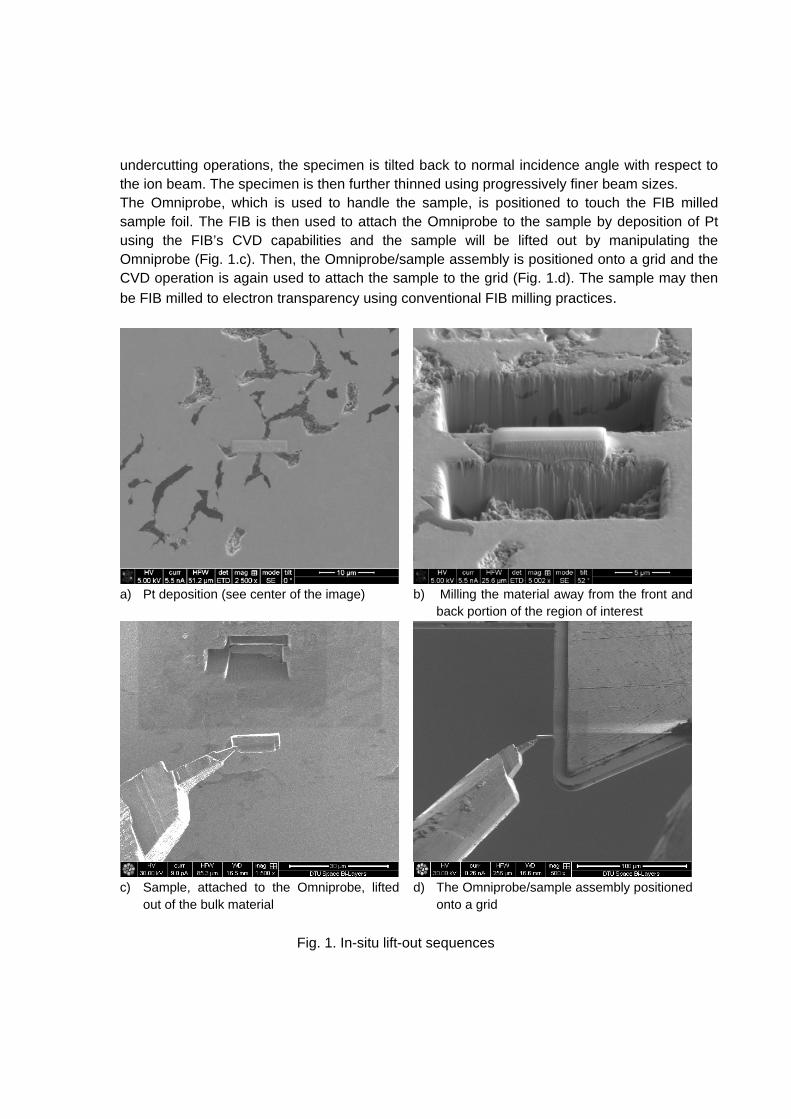
undercutting operations, the specimen is tilted back to normal incidence angle with respect to the ion beam. The specimen is then further thinned using progressively finer beam sizes. The Omniprobe, which is used to handle the sample, is positioned to touch the FIB milled sample foil. The FIB is then used to attach the Omniprobe to the sample by deposition of Pt using the FIB’s CVD capabilities and the sample will be lifted out by manipulating the Omniprobe (Fig. 1.c). Then, the Omniprobe/sample assembly is positioned onto a grid and the CVD operation is again used to attach the sample to the grid (Fig. 1.d). The sample may then
be FIB milled to electron transparency using conventional FIB milling practices.
a) Pt deposition (see center of the image)
b) Milling the material away from the front and
back portion of the region of interest
c) Sample, attached to the Omniprobe, lifted
out of the bulk material
d) The Omniprobe/sample assembly positioned
onto a grid
Fig. 1. In-situ lift-out sequences
2.2. TEM investigation
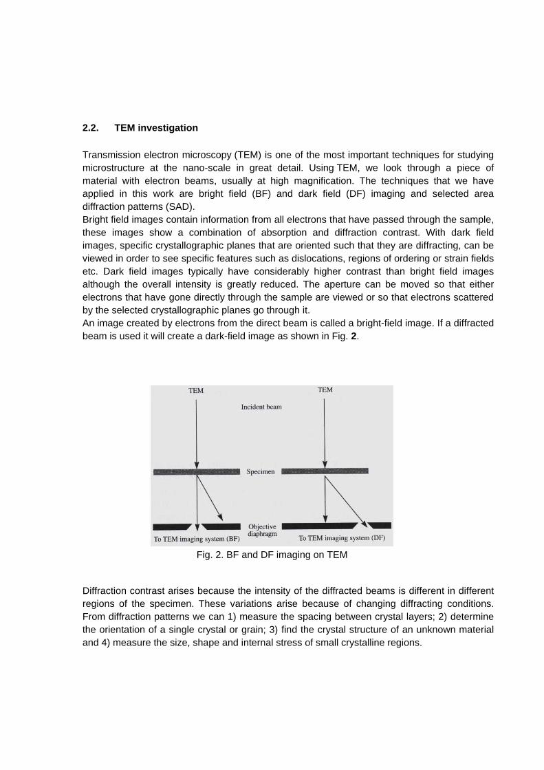
Transmission electron microscopy (TEM) is one of the most important techniques for studying microstructure at the nano-scale in great detail. Using TEM, we look through a piece of material with electron beams, usually at high magnification. The techniques that we have applied in this work are bright field (BF) and dark field (DF) imaging and selected area diffraction patterns (SAD). Bright field images contain information from all electrons that have passed through the sample, these images show a combination of absorption and diffraction contrast. With dark field images, specific crystallographic planes that are oriented such that they are diffracting, can be viewed in order to see specific features such as dislocations, regions of ordering or strain fields etc. Dark field images typically have considerably higher contrast than bright field images although the overall intensity is greatly reduced. The aperture can be moved so that either electrons that have gone directly through the sample are viewed or so that electrons scattered by the selected crystallographic planes go through it. An image created by electrons from the direct beam is called a bright-field image. If a diffracted beam is used it will create a dark-field image as shown in Fig. 2.
Fig. 2. BF and DF imaging on TEM
Diffraction contrast arises because the intensity of the diffracted beams is different in different regions of the specimen. These variations arise because of changing diffracting conditions. From diffraction patterns we can 1) measure the spacing between crystal layers; 2) determine the orientation of a single crystal or grain; 3) find the crystal structure of an unknown material and 4) measure the size, shape and internal stress of small crystalline regions.
3. Results and discussion
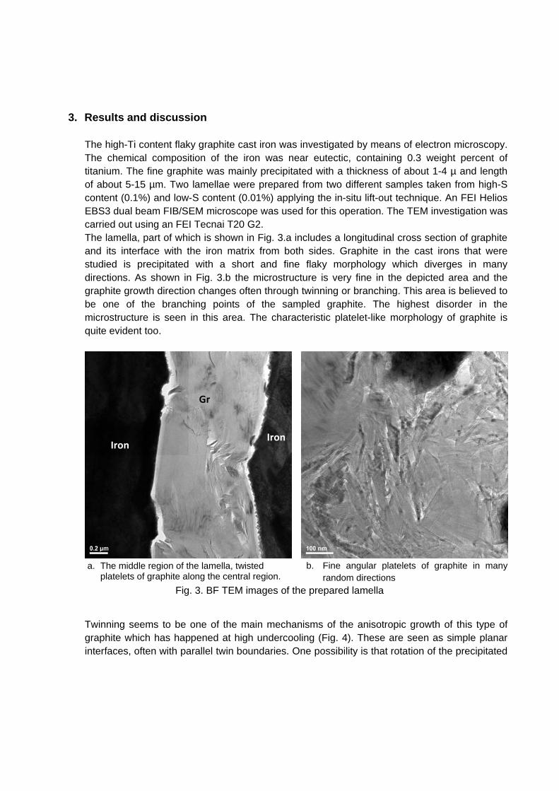
The high-Ti content flaky graphite cast iron was investigated by means of electron microscopy. The chemical composition of the iron was near eutectic, containing 0.3 weight percent of titanium. The fine graphite was mainly precipitated with a thickness of about 1-4 µ and length of about 5-15 µm. Two lamellae were prepared from two different samples taken from high-S content (0.1%) and low-S content (0.01%) applying the in-situ lift-out technique. An FEI Helios EBS3 dual beam FIB/SEM microscope was used for this operation. The TEM investigation was carried out using an FEI Tecnai T20 G2. The lamella, part of which is shown in Fig. 3.a includes a longitudinal cross section of graphite and its interface with the iron matrix from both sides. Graphite in the cast irons that were studied is precipitated with a short and fine flaky morphology which diverges in many directions. As shown in Fig. 3.b the microstructure is very fine in the depicted area and the graphite growth direction changes often through twinning or branching. This area is believed to be one of the branching points of the sampled graphite. The highest disorder in the microstructure is seen in this area. The characteristic platelet-like morphology of graphite is quite evident too.
a. The middle region of the lamella, twisted platelets of graphite along the central region.
b. Fine angular platelets of graphite in many random directions
Fig. 3. BF TEM images of the prepared lamella
Twinning seems to be one of the main mechanisms of the anisotropic growth of this type of graphite which has happened at high undercooling (Fig. 4). These are seen as simple planar interfaces, often with parallel twin boundaries. One possibility is that rotation of the precipitated
Gr
Iron Iron
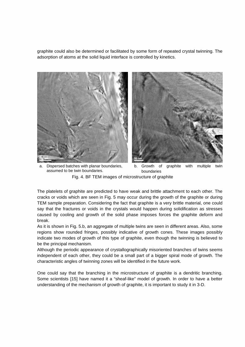
graphite could also be determined or facilitated by some form of repeated crystal twinning. The adsorption of atoms at the solid liquid interface is controlled by kinetics.
a. Dispersed batches with planar boundaries, assumed to be twin boundaries.
b. Growth of graphite with multiple twin boundaries
Fig. 4. BF TEM images of microstructure of graphite
The platelets of graphite are predicted to have weak and brittle attachment to each other. The cracks or voids which are seen in Fig. 5 may occur during the growth of the graphite or during TEM sample preparation. Considering the fact that graphite is a very brittle material, one could say that the fractures or voids in the crystals would happen during solidification as stresses caused by cooling and growth of the solid phase imposes forces the graphite deform and break. As it is shown in Fig. 5.b, an aggregate of multiple twins are seen in different areas. Also, some regions show rounded fringes, possibly indicative of growth cones. These images possibly indicate two modes of growth of this type of graphite, even though the twinning is believed to be the principal mechanism. Although the periodic appearance of crystallographically misoriented branches of twins seems independent of each other, they could be a small part of a bigger spiral mode of growth. The characteristic angles of twinning zones will be identified in the future work. One could say that the branching in the microstructure of graphite is a dendritic branching. Some scientists [15] have named it a “sheaf-like” model of growth. In order to have a better understanding of the mechanism of growth of graphite, it is important to study it in 3-D.
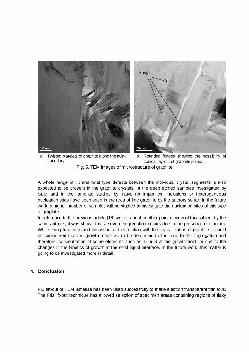
a. Twisted platelets of graphite along the twin-boundary
b. Rounded fringes showing the possibility of conical lay-out of graphite plates
Fig. 5. TEM images of microstructure of graphite
A whole range of tilt and twist type defects between the individual crystal segments is also expected to be present in the graphite crystals. In the deep etched samples investigated by SEM and in the lamellae studied by TEM, no impurities, inclusions or heterogeneous nucleation sites have been seen in the area of fine graphite by the authors so far. In the future work, a higher number of samples will be studied to investigate the nucleation sites of this type of graphite. In reference to the previous article [16] written about another point of view of this subject by the same authors, it was shown that a severe segregation occurs due to the presence of titanium. While trying to understand this issue and its relation with the crystallization of graphite, it could be considered that the growth mode would be determined either due to the segregation and therefore, concentration of some elements such as Ti or S at the growth front, or due to the changes in the kinetics of growth at the solid liquid interface. In the future work, this matter is going to be investigated more in detail.
4. Conclusion
FIB lift-out of TEM lamellae has been used successfully to make electron transparent thin foils. The FIB lift-out technique has allowed selection of specimen areas containing regions of flaky
Fringes
graphite and the surrounding cast iron matrix. The thin foils are uniform in thickness and show no apparent damage resulting from the FIB. Internal defects in the graphite flakes are seen such as multiple twin boundaries, and voids. Details of these defects, including the relative misorientations of the twins and possible spiral growth configurations have not yet been fully analyzed. Future work will include crystallographic analysis relating dark field micrographs to their associated selected area diffraction pattern.
5. Acknowledgement The authors would like to thank the “Center for electron nanoscopy” at the Technical university of
Denmark for their technical and scientific support.
1. References
[1] A. Velichko, "Quantitative 3D Characterization of Graphite Morphologies in Cast Iron using FIB Microstructure Tomography," in PhD Thesis, 2008.
[2] J. Konrad, S. Zaefferer and D. Raabe, "Investigation of orientation gradients around a hard Laves particle in," Acta Mater., vol. 54, no. 5, pp. 1369‐1380, 2006.
[3] F. Lasagni, A. Lasagni, C. Holzapfel , F. Mücklich and H. Degischer, "Three Dimensional Characterization of Unmodified and Sr‐Modified Al‐Si Eutectics by FIB and FIB EDX Tomography," Advanced Engineering Materials, vol. 8, no. 8, pp. 719‐723, 2006.
[4] D. Double and A. Hellawell, "The nucleation and growth of graphite ‐ The modification of cast iron," Acta metallurgica materialia, vol. 43, no. 6, pp. 2435‐2442, 1994.
[5] A. Velichko, A. Wiegmann and F. Mücklich, "Estimation of the effective conductivities of complex cast iron microstructures using FIB‐tomographic analysis," Acta Materialia, vol. 57, no. 5023–5035, 2009.
[6] N. Llorca‐Isern, J. Tartera, M. Espanol, M. Marsal, G. Bertran and S. Castel, "Internal features of graphite in cast irons. Confocal microscopy: useful tool for graphite growth imaging," Micron, vol. 33, no. 4, pp. 357‐64, 2002.
[7] A. Velichko, C. Holzapfel and F. Mücklich, "3D Characterization of GraphiteMorphologies in Cast Iron," Advanced Engineering Materials, vol. 9, no. 1‐2, 2007.
[8] M. Baihe, F. Keming and B. Weimin, "On The Microstructure of Graphite Spherulites in Cast Irons by TEM and HREM," Acta metall. mater., vol. 38, p. 2167, 1990.
[9] J. Tartera, N. Llorca‐Isern, M. Marsal and J. Rojas, "Similarities of nucleation and growth of spheroidal and compacted graphite," Int. Journal of Cast Metals Research, vol. 16, p. 131, 2003.
[10] D. Double and A. Hellawell, "Cone‐ helix growth forms of graphite," Acta Metallurgica, vol. 22, pp. 481‐466, 1974.
[11] W. Bian, Keming Fang, M. H. Fan, B. Miao and D. North Wood, "Structure and growth of platelets in graphite in graphite spherulites in cast iron," Journal of Materials Science, vol. 29, pp. 255‐261, 1994.

[12] I. Minkoff, Physical Metalurgy of Cast Iron, Wiley,Chichester, 1983.
[13] J. Mounchoux, C. Verdu, G. Thollet, A. Reynaud and R. Fougeres, "Morphological changes of graphite spheroids during heat treatment of ductile cast irons," Acta mater., vol. 49, p. 4355–4362, 2001 .
[14] A. Lucille and A. Giannuzzi, "Introduction to focused ion beam," North Carolina State University, 2005, pp. 247‐268.
[15] G.Faivre, "On the Mechanisms of Spherulitic Growth in Polymer and Iron Melts," Advanced Materials Research, Vols. 4‐5, pp. 17‐30, 1997.
[16] E. Moumeni, N. Tiedje and J. Hattel, "Effect of titanium on the near eutectic grey iron," in International Foundary Research, 2012.