Embed Size (px)
Citation preview

D.V. Efremov Scientific Research instituteof Electrophysical Apparatus
Scientific Technical Center SINTEZ
Scientific Technical Center TEMP
A Technical Proposal for theDevelopment and Manufacturing of Electromagnets
for the TESLA Main Extraction Line
E.Bondarchuk, N.Doinikov, V.Muratov, V.Peregud, A.Popov
TESLA 2001-216th February, 2001

Main Extraction Line Magnets
2
I. Introduction ________________________________________________________________3
II. Magnet system______________________________________________________________3
II.1 Dipoles ______________________________________________________________________ 3
II.2 Septums_____________________________________________________________________ 3
II.3 Quadrupole and half-quadrupoles ________________________________________________ 4
Conclusion ___________________________________________________________________4
Reference ____________________________________________________________________5
III. Preliminary manufacturing estimate___________________________________________5
Table II. 1 Main Extraction Line Magnets Data_________________________________________________7Table II. 2 The main parameters for the dipoles ________________________________________________8Table II. 3 The main parameters for the septums _______________________________________________8Table II. 4 The main parameters for the quadrupole and half-quadrupole magnets __________________8
Table III. 1 Preliminary cost estimation , kDEM.________________________________________________6
Fig. II. 1 The magnetization curve of the magnet steel 2081. _______________________________________9Fig. II. 2 The cross section of the dipole magnet BV1. ___________________________________________10Fig. II. 3 The cross-section of the dipole magnet BV2.___________________________________________11Fig. II. 4 BV1. The distribution of the magnetic potential function, [T⋅m]. ___________________________12Fig. II. 5 BV1. The distribution of the magnetic flux density B=const, [T]. _______________________13Fig. II. 6 BV1. Non- homogeneity of the magnetic flux density into the operation region. _____________14Fig. II. 7 BV2. The distribution of the magnetic potential function, [T⋅m].___________________________15Fig. II. 8 BV2. The distribution of the magnetic flux density B=const, [T]. _______________________16Fig. II. 9 BV2. The field distribution in the operation region. ??(?)?=const ___________________________17Fig. II. 10 The cross-section of the quadrupole magnet QED2 (MELM)____________________________18Fig. II. 11 Flux (T⋅m) lines pattern for QED2 quadrupole magnet (MELM)__________________________19Fig. II. 12 Flux density module B lines pattern for QED2 quadrupole magnet (MELM) ____________20Fig. II. 13 The cross-section of the half-quadrupole magnet (QED-QEF) (MELM)___________________21Fig. II. 14 Flux [T⋅m] lines pattern for QED-QEF mirror quadrupole magnet (MELM) _________________22Fig. II. 15 Flux density module B, [T] lines pattern for QED-QEF mirror quadrupole magnet (MELM)___23

Main Extraction Line Magnets
3
I. IntroductionThe work has been made at the D.V. Efremov Scientific Research Institute of ElectrophysicalApparatus (St. Petersburg, Russia) at the request of DESY (Hamburg, Germany) and is thetechnical proposal for development and manufacture of a number of magnets for the mainextraction line of the TESLA Project (MELM).
II. Magnet system
The magnet system consists of two dipole magnets with the horizontal field, one septum-magnet,one quadrupole and two half-quadrupoles.The main parameters are summarized in Table II.1.All magnets are conventional resistive DC-magnets. The core of most magnets is made as steellamination. The steel magnetization curve is shown in Fig.II.1. The magnet coils are made fromsquare copper conductor with a water-cooled channel. The copper conductor specific resistance isno more than 17.2 mΩ/mm2/m. The coils are water cooled. A pressure drop up to 4 bar isallowed in each of the parallel cooling loop. The coil insulation will be made with vacuumimpregnation.
II.1 Dipoles
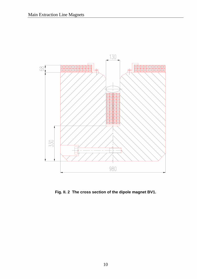
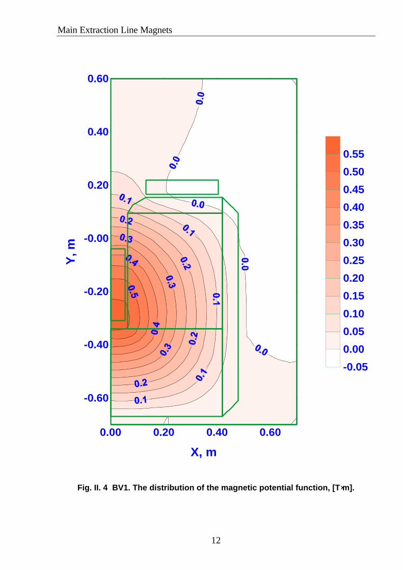
All dipoles are 4 m in length. Therefore, the magnet BV2 is divided lengthwise into two parts.The iron core is C-shaped with the yoke thickened on the underside. Both magnets are with non-salient poles; the coil is one-section in BV1 and two-section in BV2 (Figs.II.2, II.3). With thechosen design the overhang of the end parts of the coil is small. Figs. II.4 – II.6 present the resultsof the 2D calculation of the BV1 dipole: the lines ? = const, /B/ = const and field distribution inthe operation region of the magnet. The similar results for the BV2 dipoles are shown inFigs.II.7 – II.9.When the occasion requires, the magnets can be shimmed so as to improve the distribution of themagnetic field.The configuration of the C-type iron core facilitates the vacuum chamber installation andmaintenance, as well as simplifies magnetic measurements. It makes no sense to manufacture theC-type dipoles as laminated, because it is difficult to provide the geometrical tolerances afterstamping and welding.The final decision on selecting the type of dipole iron core will be made at further design stages.Each coil is made of a conductor with a water-cooled channel. The coils of the C-type magnetscan be mounted on the iron core by slipping it through the gap, thus simplifying replacement of adamaged coil. The dipoles operate at different field strength values, as shown in Table II.1. Themain parameters of the dipoles are presented in Table II.2.
II.2 Septums
The MSEP and VSEPTUM magnets are similar in design and are made as one-turn septum-magnets. The general view of the magnets and their main parameters are shown in Drawings1? .516.810, 1? .516.819. The magnet turn consists of two parts, i.e. a thin frontal conductor anda thick slot conductor. This makes it possible to arrange the magnet in the region, where thevacuum chambers of two beams are located close to each other, to generate the necessary field onone of the beams and the minimum scattering field on the other.
Main Extraction Line Magnets
4
The frontal conductor 5 mm thick is brazed by silver-content braze from twelve copper tubes 5×7- ∅3 in size. Ten central holes of the conductor provide cooling water flow. Two outer holes areplugged. In their locations the conductor is fastened to clamping bars. The frontal conductor hasno electric insulation and is in contact with the iron core. Sheets of the laminated iron core arecemented together by insulation compound. The clamping bars fastening the frontal conductor aremade of aluminum alloy and have an oxide insulation coating.The slot conductor is brazed from two copper tubes 23 × 41 - ∅8 mm in size. The conductor isinsulated by glass tape with epoxy compound. The insulation thickness is 1.5 mm.On one side of the magnet the frontal and slot conductors are brazed with each other to form thecommon water cooling path. On the other side of the magnet current and water are suppliedthrough copper tubes, identical to those used for the slot conductor.The iron core sheets are under potential of the frontal conductor. Therefore the magnet has asupport plate insulated electrically against the iron core.The winding turn is made as a very short cooling path. Hence, to reduce water velocity to anacceptable value it is necessary to provide a pressure difference on the winding no more than 1.5bar. The calculations show that heating of the frontal conductor at a current density of 37 ? /m2does not exceed 9°? .Two design versions of the magnet are developed. In the first version (Drawing 1? .516.810) thefrontal and slot conductors are divided in two in the end parts and folded in different directions.The magnet dimensions in this case are minimum.In the second version (Drawing.1? .516.810) the end parts of the conductor are folded in onedirection. The magnet dimensions are increased by 80 mm, but it becomes possible to remove thewinding from the iron core and to insert the vacuum chamber with wide flanges into the magnetgap.
II.3 Quadrupole and half-quadrupoles
The major requirements for the quadrupole and half-quadrupole are given in Table II.1. Themagnet system MELM contains one quadrupole in QED2 with the aperture 2?=120 mm and fieldon the pole Bp=1.04T and two half-quadrupoles (QED and QEF) with the radius ?=70 mm andfield on the pole Bp=1.3 T. The length of each magnet is 5 m.All magnets were simulated by the code OPERA2D[3].Fig. II.10-12 shows the calculation model of the quadrupole QED2 and the results of itssimulation. To simplify manufacturing the length of one quadrupole L=1.7 m, and QED2 consistsof three such quadrupoles.When developing the half-quadrupoles use was made of the experience in designing similarmagnets for the Luminosity Upgrade [4] Project. To equalize flows in the central region of themirror plate the iron core is thickened in the vicinity of the upper and lower coils. Fig. II.13 showsthe quadrupole cross-section, and Figs..II.14 and II.15 present the simulation results. Each half-quadrupole consists of two magnets with the length L=2.5 m each. The septum size in the mirrorplate is 10 mm.The main parameters of the quadrupole magnets are given in Table II.4.
ConclusionThis work has been performed on the basis of the estimate of electromagnetic calculations andpreliminary studies of the magnet construction.

Main Extraction Line Magnets
5
Reference[1] POISSON Group Programs User’s Guide, 1975.[2] N. Bogatov, E. Bondarchuk et al., Normal Conducting QI and QJ Quadrupoles for the ITER
Luminosity Upgrade, Proc. EPAC-98, Stockholm, p.1963.[3] OPERA 2D reference manual, VF-01-97-24, Vector Fields Limited, 24 Bankside, Kidlington,
Oxford 0 x 5 IJE.[4] E.Bondarchuk et al., Precision Septum Half-Quadrupoles for the HERA Lumi-Upgrade.
MT-16, Florida, USA, 1999, p.p. 268-271.
III. Preliminary manufacturing cost estimate
The preliminary cost estimate of the magnets for the Main Extraction Line was made onassumption that all magnets will be produced by one supplier with appropriate experience andfacilities. With such an approach the number of tooling sets and the cost of their production willbe minimum.This cost estimate was made by the D.V.Efremov Institute in 2000.The following prices for the basic materials were taken for cost calculation:· copper conductor ≈ 25 – 30 DEM/kg (depending on cross-section area);· sheet steel for laminated yokes ≈ 2,5 DEM/kg;· iron plates for solid yokes ≈ 2,0 DEM/kg.In order to make into account possible complication in the final design when working out thedrawings for manufacturing the need might arise to make appropriate corrections.The results of cost calculation are presented in Table No. III.1.

Main Extraction Line Magnets
6
Table III. 1 Preliminary cost estimation , kDEM.
Or-dinal
? DenominationBV1 BV2 MSEP QED
QEFQED2
Sketch ? 1A516820 1A516821 1A516810 1A516823 1A516818
1. Design ofmanufacturingdrawings.
60,0 75,0 65,0 45,0 75,0
2. Tooling. 140,0 170,0 160,0 256,0 280,0
3.3.1.
3.2.3.3.
Materials:Steel for magnetyoke.Copper conductor.Insulation materials.
Total as per point 3 :
62,8
52,814,1
129,5
36,0
38,311,6
85,9
1,5
2,00,3
3,8
20,4
10,54,8
35,7
18,6
15,85,9
40,3
4.4.1.4.2.4.3.
4.4.
Production :Coils .Yoke.Other details,including material.Magnets assembly.
Total as per point 4 :
19,528,86,8
7,4
62,5
22,523,06,5
7,1
59,1
8,513,211,5
5,0
31,2
18,425,27,4
7,8
58,8
38,520,96,9
8,4
74,7
5. Cost of onemagnet (point 3+point 4 ).
192,0 145,0 35,0 94,5 115,0
6. Quantity of magnets. 1 2 11 4 37. Total cost
excluding p.1 and2.
192,0 290,0 385,0 378,0 345,0
8. Total costincluding p.1 andp. 2.
392,0 535,0 610,0 679,0 700,0
9. TOTAL: 2.916,0

Main Extraction Line Magnets
7
Table II. 1 Main Extraction Line Magnets Data
DIPOLE
? Label typenumber
ofmagnets
corelength
m
z from IPm angle
mradK
m-2
Aperturehalf X half Ymm mm
Pole tipfields, T
1. BV1 V Dipole 1 4 105.51 4 0 65 30 1.33422. BV2 V Dipole 1 8 140.508 7.332 0 45 40 1.2228
SEPTUM
? Label typenumber
ofmagnets
corelength
m
z from IPm angle
mradK
m-2
Aperturehalf X half Ymm mm
Pole tipfields, T
1. MSEP V Septum 1 16 55 2.1 0 40 43 0.17512
QUADRUPOLE and HALF-QUADRUPOLES
? Label typenumber
ofmagnets
corelength
m
z from IPm angle
mradK
m-2
Aperturehalf X half Ymm mm
Pole tipfields, T
1. QED Half-quad. 1 5 92.0 0 0.013 75 75 1.30092. QEF Half-quad. 1 5 100.01 0 -0.013 75 75 -1.30093 QED2 Quadrupole 1 5 133.009 0 0.0013 60 60 1.0407

Main Extraction Line Magnets
8
Table II. 2 The main parameters for the dipoles
? Label Air Gap mm
CoreLength m
Number ofmagnets
Magnetic Fields T
Current A
Voltage drop V
Power Loss kW
Totalweight Kg
Water Flow Rate l /min
Temperature overheating °C
1 BV1 130 4 1 1.37 3600 43.3 156 25100 68.8 332 BV2 90 4 2 1.23 1364 73 99.5 13700 58 35
Table II. 3 The main parameters for the septums
? Label Air Gap mm
CoreLength m
Number ofmagnets
Magnetic Fields T
Current A
Voltage drop V
Power Loss kW
Totalweight kg
Water Flow Rate l /min
Temperature overheating °C
1 MSEP 90 1.5 11 0.175 12000 1.5 18.4 240 12.6 21
Table II. 4 The main parameters for the quadrupole and half-quadrupole magnets
? LabelPole tipradius(mm)
CoreLength
m
Numberof
magnets
Poletip
fieldsT
CurrentA
Voltagedrop
V
PowerlosskW
Totalweight
kg
WaterFlowRatel/min
Temperatureoverheating
°C
1 QED (half) 75 2.5 2 1.31 986 114 112.1 5000 47 422 QEF (half) 75 2.5 2 1.31 986 114 112.1 5000 47 423 QED2 60 1.7 3 1.04 372 204 75.7 4100 31.2 41

Main Extraction Line Magnets
9
H, [A/M] B, [T]0. 0.000
50. 0.02870. 0.059
100. 0.200200. 0.764250. 0.940350. 1.168500. 1.339800. 1.497
1000. 1.5422500. 1.672
12000. 1.88020000. 2.00080000. 2.300
Fig. II. 1 The magnetization curve of the magnet steel 2081.
10 100 1000 10000 100000H, A/M
0.0
0.5
1.0
1.5
2.0
2.5
B, T
Steel 2081
Main Extraction Line Magnets
10
Fig. II. 2 The cross section of the dipole magnet BV1.

Main Extraction Line Magnets
11
Fig. II. 3 The cross-section of the dipole magnet BV2.
Main Extraction Line Magnets
12
Fig. II. 4 BV1. The distribution of the magnetic potential function, [T⋅m].
0.00 0.20 0.40 0.60
X, m
-0.60
-0.40
-0.20
-0.00
0.20
0.40
0.60Y
, m
-0.05
0.00
0.05
0.10
0.15
0.20
0.25
0.30
0.35
0.40
0.45
0.50
0.55

Main Extraction Line Magnets
13
Fig. II. 5 BV1. The distribution of the magnetic flux density B=const, [T].
0.00 0.20 0.40 0.60
X, m
-0.60
-0.40
-0.20
-0.00
0.20
0.40
0.60Y
, m
0.000.100.200.300.400.500.600.700.800.901.001.101.201.301.401.501.601.701.80

Main Extraction Line Magnets
14
Fig. II. 6 BV1. Non- homogeneity of the magnetic flux density into the operationregion.
(B−? 0) ⁄ ? 0 , ?=const
0.00 0.01 0.02 0.03 0.04 0.05 0.06 0.07X, m (y=const)
-0.01
-0.01
-0.00
0.00
0.00
0.01
(B-B
o)/
Bo
y = -0.030 m
y = -0.0 m
y = 0.030 m

Main Extraction Line Magnets
15
Fig. II. 7 BV2. The distribution of the magnetic potential function, [T⋅m].
A =const
0.00 0.10 0.20 0.30 0.40 0.50-0.70
-0.60
-0.50
-0.40
-0.30
-0.20
-0.10
0.00
0.10
0.20
0.30
-0.020.000.020.040.060.080.100.120.140.160.180.200.220.240.260.280.300.320.340.36
0.00 0.10 0.20 0.30 0.40 0.50-0.70
-0.60
-0.50
-0.40
-0.30
-0.20
-0.10
0.00
0.10
0.20
0.30
0.00 0.10 0.20 0.30 0.40 0.50-0.70
-0.60
-0.50
-0.40
-0.30
-0.20
-0.10
0.00
0.10
0.20
0.30

Main Extraction Line Magnets
16
Fig. II. 8 BV2. The distribution of the magnetic flux density B=const, [T].
0.00 0.10 0.20 0.30 0.40 0.50-0.70
-0.60
-0.50
-0.40
-0.30
-0.20
-0.10
0.00
0.10
0.20
0.30
0.10
0.40
0.60
0.70
0.90
1.00
1.20
1.30
1.40
1.50
1.60
0.00 0.10 0.20 0.30 0.40 0.50-0.70
-0.60
-0.50
-0.40
-0.30
-0.20
-0.10
0.00
0.10
0.20
0.30
0.00 0.10 0.20 0.30 0.40 0.50-0.70
-0.60
-0.50
-0.40
-0.30
-0.20
-0.10
0.00
0.10
0.20
0.30

Main Extraction Line Magnets
17
Fig. II. 9 BV2. The field distribution in the operation region. ??(?)?=const
( )00
)0(/)0()(===
−=yxyxconstyx BBxBk
1 – y=0.04 ? ? .2 – y=0.03 – y= - 0.04 ? ? .
0.00 0.01 0.02 0.03 0.04
-0.003
-0.002
-0.001
0.000
0.001
0.002
3
1
2
X (m)
k

Main Extraction Line Magnets
18
Fig. II. 10 The cross-section of the quadrupole magnet QED2 (MELM)

Main Extraction Line Magnets
19
Fig. II. 11 Flux (T⋅m) lines pattern for QED2 quadrupole magnet (MELM)
(AW=25.645 kA, Bp=1.06T)

Main Extraction Line Magnets
20
Fig. II. 12 Flux density module B lines pattern for QED2 quadrupole magnet (MELM)
(AW=25.645 kA, Bp=1.06T)

Main Extraction Line Magnets
21
Fig. II. 13 The cross-section of the half-quadrupole magnet (QED-QEF) (MELM)

Main Extraction Line Magnets
22
Fig. II. 14 Flux [T⋅m] lines pattern for QED-QEF mirror quadrupole magnet (MELM)
(AW=41.413 kA, Bp=1.31T)

Main Extraction Line Magnets
23
Fig. II. 15 Flux density module B, [T] lines pattern for QED-QEF mirror quadrupole magnet (MELM)
(AW=41.413 kA, Bp=1.31T)