Embed Size (px)
Citation preview
267LOGO! ManualA5E00380835-02
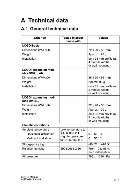
A Technical dataA.1 General technical data
Criterion Tested in accor-dance with
Values
LOGO!Basic
Dimensions (WxHxD) 72 x 90 x 55 mm
Weight Approx. 190 g
Installation on a 35 mm profile rail4 module widthsor wall mounting
LOGO! expansion mod-ules DM8..., AM...
Dimensions (WxHxD) 36 x 90 x 53 mm
Weight Approx. 90 g
Installation on a 35 mm profile rail2 module widthsor wall mounting
LOGO! expansion mod-ules DM16...Dimensions (WxHxD) 72 x 90 x 53 mm
Weight Approx. 190 g
Installation on a 35 mm profile rail4 module widthsor wall mounting
Climatic conditions
Ambient temperature
Horizontal installation
Low temperature toIEC 60068-2-1 0 ... 55 ˚CHorizontal installation
Vertical installation
IEC 60068 2 1High temperatureto IEC 60068-2-2
0 ... 55 C
0 ... 55 ˚C
Storage/shipping -40 ˚C ... +70 ˚CRelative humidity IEC 60068-2-30 From 10 to 95 %
no condensation
Air pressure 795 ... 1080 hPa

LOGO! ManualA5E00380835-02268
Criterion ValuesTested in accor-dance with
Pollutants IEC 60068-2-42
IEC 60068-2-43
SO2 10 cm3 /m3,4 days
H2S 1 cm3 /m3,4 days
Ambient mechanical conditions
Protection mode IP20
Vibrations: IEC 60068-2-6 5 ... 9 Hz (constantamplitude 3.5 mm)
9 ... 150 Hz (constantacceleration 1 g)
Shock IEC 60068-2-27 18 shocks(half-sine wave15g/11 ms)
Drop IEC 60068-2-31 Drop height 50 mm
Free fall (packaged) IEC 60068-2-32 1 m
Electromagnetic compatibility (EMC)
Noise emission EN 55011/AEN 55022/B
EN 50081-1(domestic area)
Limit class B group 1
Electrostatic discharge IEC 61000-4-2
Severity 3
8 kV air discharge
6 kV contact discharge
Electromagnetic fields IEC 61000-4-3 Field strength 10 V/m
HF currents on cables andcable shielding
IEC 61000-4-6 10 V
Burst pulses IEC 61000-4-4Severity 3
2 kV (supply and sig-nal lines)
High-energy surge pulse(applies only toLOGO! 230 ...)
IEC 61000-4-5Severity 3
1 kV (power lines)symmetrical
2 kV (power lines)asymmetrical
(24VDC circuits re-quire external surgeprotection.)
Technical data
269LOGO! ManualA5E00380835-02
Criterion ValuesTested in accor-dance with
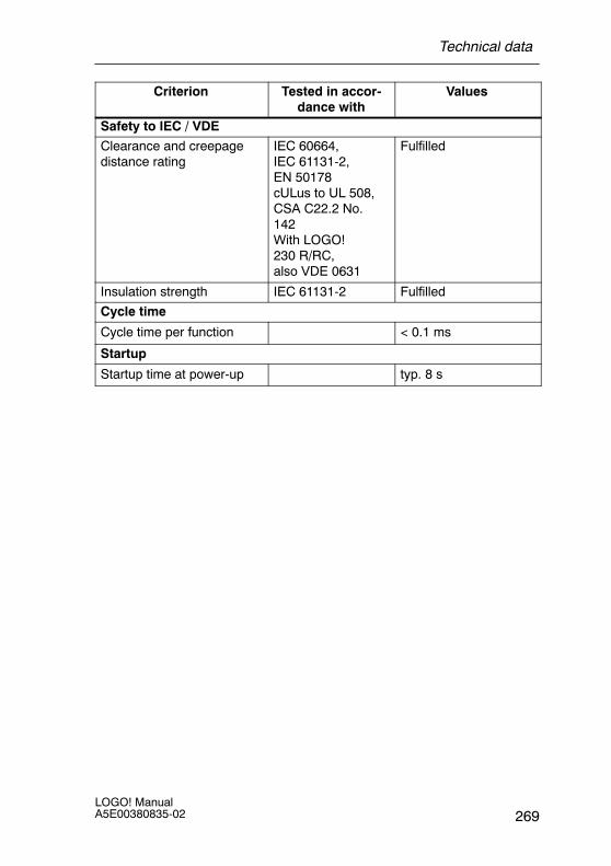
Safety to IEC / VDE
Clearance and creepagedistance rating
IEC 60664,IEC 61131-2,EN 50178cULus to UL 508,CSA C22.2 No.142With LOGO!230 R/RC,also VDE 0631
Fulfilled
Insulation strength IEC 61131-2 Fulfilled
Cycle time
Cycle time per function < 0.1 ms
Startup
Startup time at power-up typ. 8 s
Technical data
LOGO! ManualA5E00380835-02270
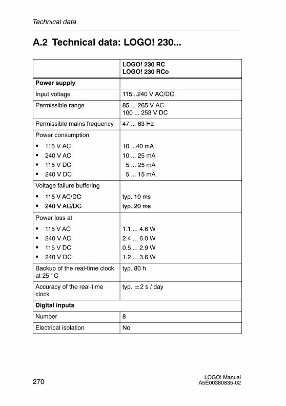
A.2 Technical data: LOGO! 230...
LOGO! 230 RCLOGO! 230 RCo
Power supply
Input voltage 115...240 V AC/DC
Permissible range 85 ... 265 V AC100 ... 253 V DC
Permissible mains frequency 47 ... 63 Hz
Power consumption
S 115 V AC 10 ...40 mA
S 240 V AC 10 ... 25 mA
S 115 V DC 5 ... 25 mA
S 240 V DC 5 ... 15 mA
Voltage failure buffering
S 115 V AC/DC typ 10 msS 115 V AC/DC typ. 10 ms
S 240 V AC/DC
yp
typ 20 msS 240 V AC/DC typ. 20 ms
Power loss at
S 115 V AC 1.1 ... 4.6 W
S 240 V AC 2.4 ... 6.0 W
S 115 V DC 0.5 ... 2.9 W
S 240 V DC 1.2 ... 3.6 W
Backup of the real-time clockat 25 _C
typ. 80 h
Accuracy of the real-timeclock
typ.2 s / day
Digital inputs
Number 8
Electrical isolation No
Technical data
271LOGO! ManualA5E00380835-02
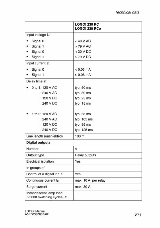
LOGO! 230 RCLOGO! 230 RCo
Input voltage L1
S Signal 0
S Signal 1
S Signal 0
S Signal 1
< 40 V AC
> 79 V AC
< 30 V DC
> 79 V DC
Input current at
S Signal 0 < 0.03 mAg
S Signal 1 > 0.08 mA
Delay time at
S 0 to 1: 120 V AC
: 240 V AC
: 120 V DC
: 240 V DC
typ. 50 ms
typ. 30 ms
typ. 25 ms
typ. 15 ms
S 1 to 0: 120 V AC
: 240 V AC
: 120 V DC
: 240 V DC
typ. 65 ms
typ. 105 ms
typ. 95 ms
typ. 125 ms
Line length (unshielded) 100 m
Digital outputs
Number 4
Output type Relay outputs
Electrical isolation Yes
In groups of 1
Control of a digital input Yes
Continuous current Ith max. 10 A per relay
Surge current max. 30 A
Incandescent lamp load(25000 switching cycles) at
Technical data
LOGO! ManualA5E00380835-02272
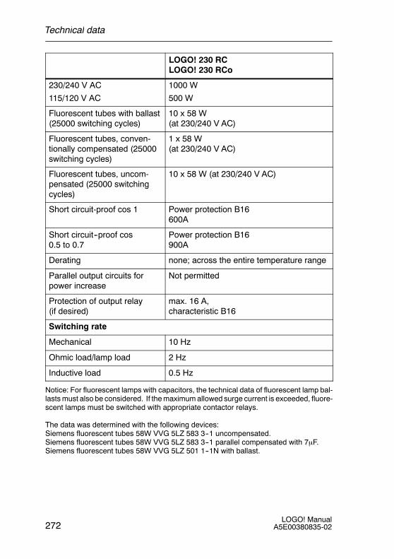
LOGO! 230 RCLOGO! 230 RCo
230/240 V AC
115/120 V AC
1000 W
500 W
Fluorescent tubes with ballast(25000 switching cycles)
10 x 58 W(at 230/240 V AC)
Fluorescent tubes, conven-tionally compensated (25000switching cycles)
1 x 58 W(at 230/240 V AC)
Fluorescent tubes, uncom-pensated (25000 switchingcycles)
10 x 58 W (at 230/240 V AC)
Short circuit-proof cos 1 Power protection B16600A
Short circuit--proof cos0.5 to 0.7
Power protection B16900A
Derating none; across the entire temperature range
Parallel output circuits forpower increase
Not permitted
Protection of output relay(if desired)
max. 16 A,characteristic B16
Switching rate
Mechanical 10 Hz
Ohmic load/lamp load 2 Hz
Inductive load 0.5 Hz
Notice: For fluorescent lamps with capacitors, the technical data of fluorescent lamp bal-lasts must also be considered. If the maximum allowed surge current is exceeded, fluore-scent lamps must be switched with appropriate contactor relays.
The data was determined with the following devices:Siemens fluorescent tubes 58W VVG 5LZ 583 3--1 uncompensated.Siemens fluorescent tubes 58W VVG 5LZ 583 3--1 parallel compensated with 7μF.Siemens fluorescent tubes 58W VVG 5LZ 501 1--1N with ballast.
Technical data

273LOGO! ManualA5E00380835-02
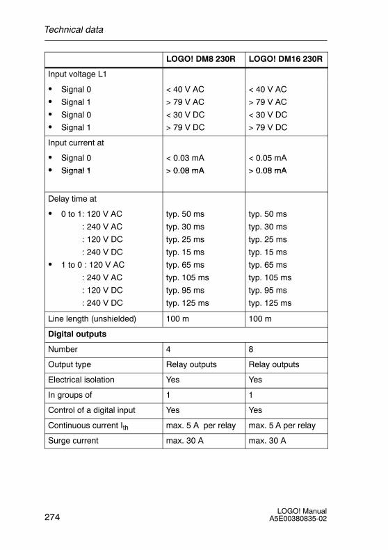
A.3 Technical data: LOGO! DM8 230R andLOGO! DM16 230R
LOGO! DM8 230R LOGO! DM16 230R
Power supply
Input voltage 115...240 V AC/DC 115 ... 240 V AC/DC
Permissible range 85 ... 265 V AC100 ... 253 V DC
85 ... 265 V AC100 ... 253 V DC
Permissible mains frequency 47 ... 63 Hz 47 ... 63 Hz
Power consumption
S 115 V AC 10 ... 30 mA 10 ... 60 mA
S 240 V AC 10 ... 20 mA 10 ... 40 mA
S 115 V DC 5 ... 15 mA 5 ... 25 mA
S 240 V DC 5 ... 10 mA 5 ... 20 mA
Voltage failure buffering
S 115 V AC/DC typ 10 ms typ 10 msS 115 V AC/DC typ. 10 ms typ. 10 ms
S 240 V AC/DC
yp
typ 20 ms
yp
typ 20 msS 240 V AC/DC typ. 20 ms typ. 20 ms
Power loss at
S 115 V AC 1.1 ... 3.5 W 1.1 ... 4.5 W
S 240 V AC 2.4 ... 4.8 W 2.4 ... 5.5 W
S 115 V DC 0.5 ... 1.8 W 0.6 ... 2.9 W
S 240 V DC 1.2 ... 2.4 W 1.2 ... 4.8 W
Backup of the real-time clockat 25 _C
Accuracy of the real-timeclock
Digital inputs
Number 4 8
Electrical isolation No No
Technical data
LOGO! ManualA5E00380835-02274
LOGO! DM16 230RLOGO! DM8 230R
Input voltage L1
S Signal 0
S Signal 1
S Signal 0
S Signal 1
< 40 V AC
> 79 V AC
< 30 V DC
> 79 V DC
< 40 V AC
> 79 V AC
< 30 V DC
> 79 V DC
Input current at
S Signal 0
S Signal 1
< 0.03 mA
> 0 08 mA
< 0.05 mA
> 0 08 mAS Signal 1 > 0.08 mA > 0.08 mA
Delay time at
S 0 to 1: 120 V AC
: 240 V AC
: 120 V DC
: 240 V DC
typ. 50 ms
typ. 30 ms
typ. 25 ms
typ. 15 ms
typ. 50 ms
typ. 30 ms
typ. 25 ms
typ. 15 ms
S 1 to 0 : 120 V AC
: 240 V AC
: 120 V DC
: 240 V DC
yp
typ. 65 ms
typ. 105 ms
typ. 95 ms
typ. 125 ms
yp
typ. 65 ms
typ. 105 ms
typ. 95 ms
typ. 125 ms
Line length (unshielded) 100 m 100 m
Digital outputs
Number 4 8
Output type Relay outputs Relay outputs
Electrical isolation Yes Yes
In groups of 1 1
Control of a digital input Yes Yes
Continuous current Ith max. 5 A per relay max. 5 A per relay
Surge current max. 30 A max. 30 A
Technical data
275LOGO! ManualA5E00380835-02
LOGO! DM16 230RLOGO! DM8 230R
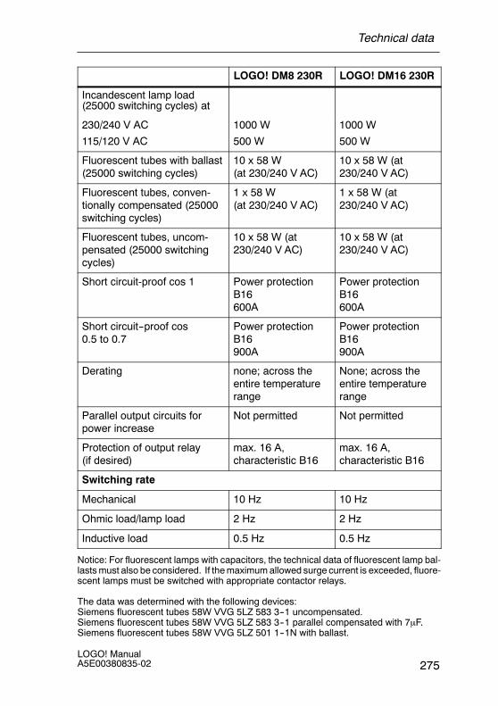
Incandescent lamp load(25000 switching cycles) at
230/240 V AC
115/120 V AC
1000 W
500 W
1000 W
500 W
Fluorescent tubes with ballast(25000 switching cycles)
10 x 58 W(at 230/240 V AC)
10 x 58 W (at230/240 V AC)
Fluorescent tubes, conven-tionally compensated (25000switching cycles)
1 x 58 W(at 230/240 V AC)
1 x 58 W (at230/240 V AC)
Fluorescent tubes, uncom-pensated (25000 switchingcycles)
10 x 58 W (at230/240 V AC)
10 x 58 W (at230/240 V AC)
Short circuit-proof cos 1 Power protectionB16600A
Power protectionB16600A
Short circuit--proof cos0.5 to 0.7
Power protectionB16900A
Power protectionB16900A
Derating none; across theentire temperaturerange
None; across theentire temperaturerange
Parallel output circuits forpower increase
Not permitted Not permitted
Protection of output relay(if desired)
max. 16 A,characteristic B16
max. 16 A,characteristic B16
Switching rate
Mechanical 10 Hz 10 Hz
Ohmic load/lamp load 2 Hz 2 Hz
Inductive load 0.5 Hz 0.5 Hz
Notice: For fluorescent lamps with capacitors, the technical data of fluorescent lamp bal-lasts must also be considered. If the maximum allowed surge current is exceeded, fluore-scent lamps must be switched with appropriate contactor relays.
The data was determined with the following devices:Siemens fluorescent tubes 58W VVG 5LZ 583 3--1 uncompensated.Siemens fluorescent tubes 58W VVG 5LZ 583 3--1 parallel compensated with 7μF.Siemens fluorescent tubes 58W VVG 5LZ 501 1--1N with ballast.
Technical data
LOGO! ManualA5E00380835-02276
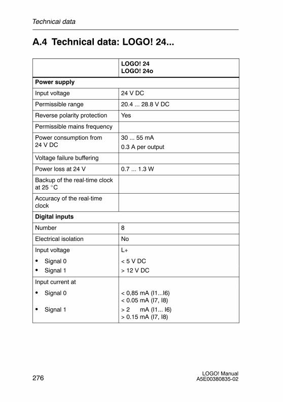
A.4 Technical data: LOGO! 24...
LOGO! 24LOGO! 24o
Power supply
Input voltage 24 V DC
Permissible range 20.4 ... 28.8 V DC
Reverse polarity protection Yes
Permissible mains frequency
Power consumption from24 V DC
30 ... 55 mA
0.3 A per output
Voltage failure buffering
Power loss at 24 V 0.7 ... 1.3 W
Backup of the real-time clockat 25 _C
Accuracy of the real-timeclock
Digital inputs
Number 8
Electrical isolation No
Input voltage L+
S Signal 0 < 5 V DCg
S Signal 1 > 12 V DC
Input current at
S Signal 0 < 0,85 mA (I1...I6)< 0.05 mA (I7, I8)
S Signal 1
( , )
> 2 mA (I1... I6)> 0.15 mA (I7, I8)
Technical data

277LOGO! ManualA5E00380835-02
LOGO! 24LOGO! 24o
Delay time at
S 0 to 1 typ. 1.5 ms
<1.0 ms (I5, I6)
S 1 to 0
( , )
typ. 1.5 ms
<1.0 ms (I5, I6)
Line length (unshielded) 100 m
Analog inputs
Number 2 (I7 = AI1, I8 = AI2)
Range 0 ... 10 V DCinput impedance 78 kΩ
Cycle time for analog valuegeneration
300 ms
max. input voltage 28.8 V DC
Line length (shielded andtwisted)
10 m
Error limit +/-- 1.5%
Digital outputs
Number 4
Output type Transistor,current-sourcing (1)
Electrical isolation No
In groups of
Control of a digital input Yes
Output voltage ≙ Supply voltage
Output current max. 0.3 A
Continuous current Ith
Incandescent lamp load(25000 switching cycles) at
Fluorescent tubes with ballast(25000 switching cycles)
Technical data
LOGO! ManualA5E00380835-02278
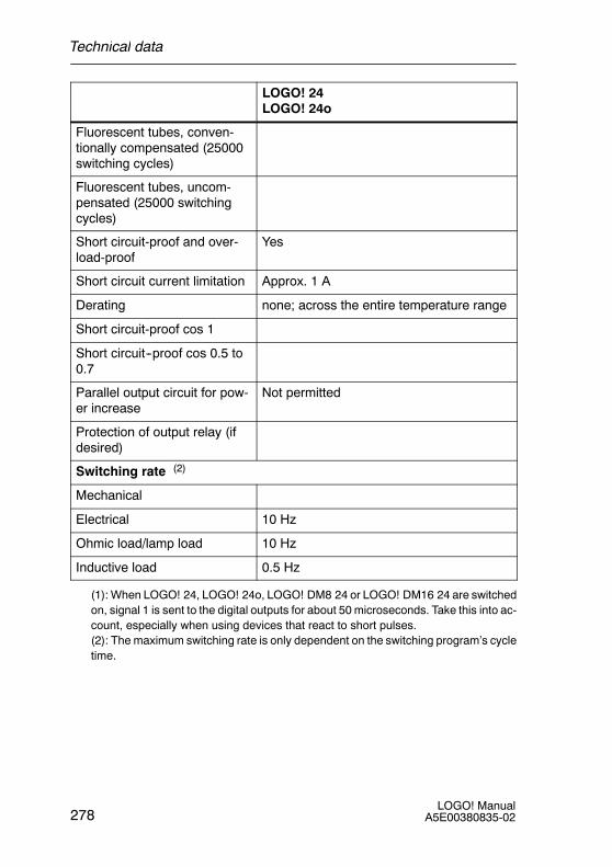
LOGO! 24LOGO! 24o
Fluorescent tubes, conven-tionally compensated (25000switching cycles)
Fluorescent tubes, uncom-pensated (25000 switchingcycles)
Short circuit-proof and over-load-proof
Yes
Short circuit current limitation Approx. 1 A
Derating none; across the entire temperature range
Short circuit-proof cos 1
Short circuit--proof cos 0.5 to0.7
Parallel output circuit for pow-er increase
Not permitted
Protection of output relay (ifdesired)
Switching rate (2)
Mechanical
Electrical 10 Hz
Ohmic load/lamp load 10 Hz
Inductive load 0.5 Hz
(1): When LOGO! 24, LOGO! 24o, LOGO! DM8 24 or LOGO! DM16 24 are switchedon, signal 1 is sent to the digital outputs for about 50 microseconds. Take this into ac-count, especially when using devices that react to short pulses.(2): The maximum switching rate is only dependent on the switching program’s cycletime.
Technical data
279LOGO! ManualA5E00380835-02
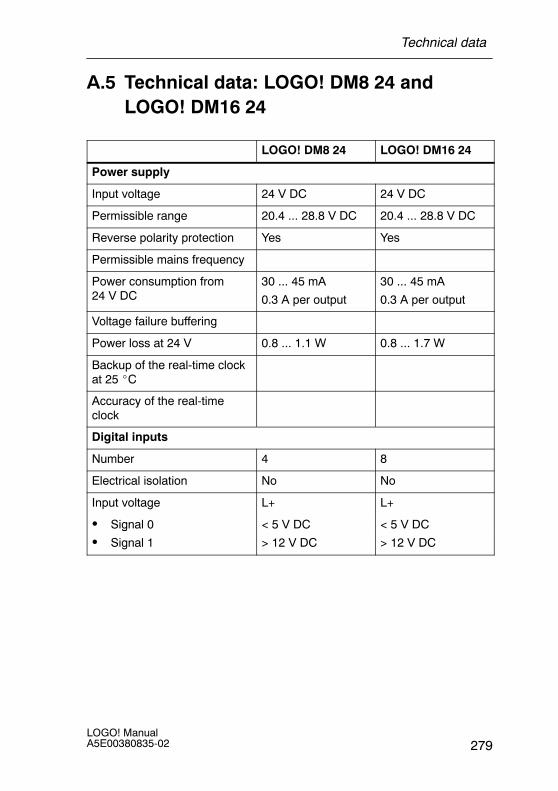
A.5 Technical data: LOGO! DM8 24 andLOGO! DM16 24
LOGO! DM8 24 LOGO! DM16 24
Power supply
Input voltage 24 V DC 24 V DC
Permissible range 20.4 ... 28.8 V DC 20.4 ... 28.8 V DC
Reverse polarity protection Yes Yes
Permissible mains frequency
Power consumption from24 V DC
30 ... 45 mA
0.3 A per output
30 ... 45 mA
0.3 A per output
Voltage failure buffering
Power loss at 24 V 0.8 ... 1.1 W 0.8 ... 1.7 W
Backup of the real-time clockat 25 _C
Accuracy of the real-timeclock
Digital inputs
Number 4 8
Electrical isolation No No
Input voltage L+ L+
S Signal 0 < 5 V DC < 5 V DCg
S Signal 1 > 12 V DC > 12 V DC
Technical data
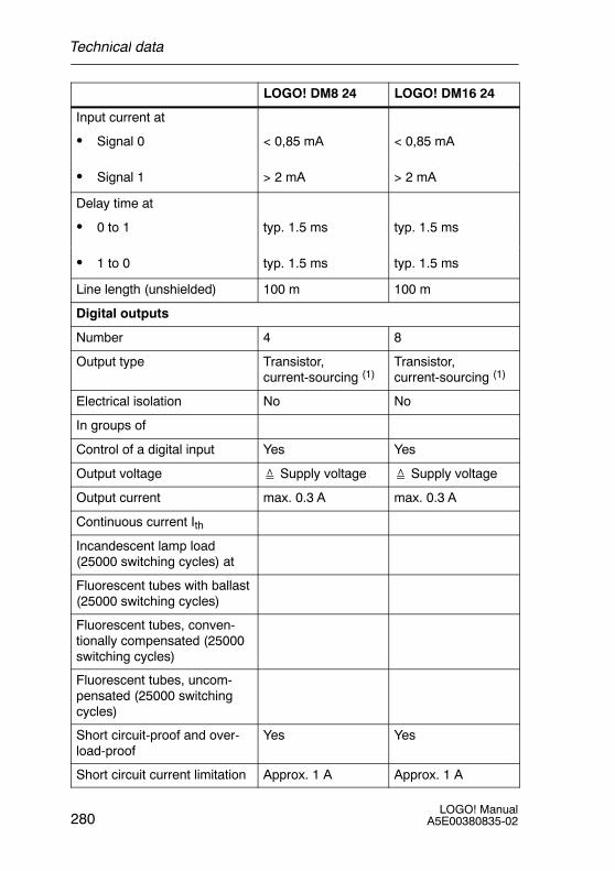
LOGO! ManualA5E00380835-02280
LOGO! DM16 24LOGO! DM8 24
Input current at
S Signal 0 < 0,85 mA < 0,85 mA
S Signal 1 > 2 mA > 2 mA
Delay time at
S 0 to 1 typ. 1.5 ms typ. 1.5 ms
S 1 to 0 typ. 1.5 ms typ. 1.5 ms
Line length (unshielded) 100 m 100 m
Digital outputs
Number 4 8
Output type Transistor,current-sourcing (1)
Transistor,current-sourcing (1)
Electrical isolation No No
In groups of
Control of a digital input Yes Yes
Output voltage ≙ Supply voltage ≙ Supply voltage
Output current max. 0.3 A max. 0.3 A
Continuous current Ith
Incandescent lamp load(25000 switching cycles) at
Fluorescent tubes with ballast(25000 switching cycles)
Fluorescent tubes, conven-tionally compensated (25000switching cycles)
Fluorescent tubes, uncom-pensated (25000 switchingcycles)
Short circuit-proof and over-load-proof
Yes Yes
Short circuit current limitation Approx. 1 A Approx. 1 A
Technical data
281LOGO! ManualA5E00380835-02
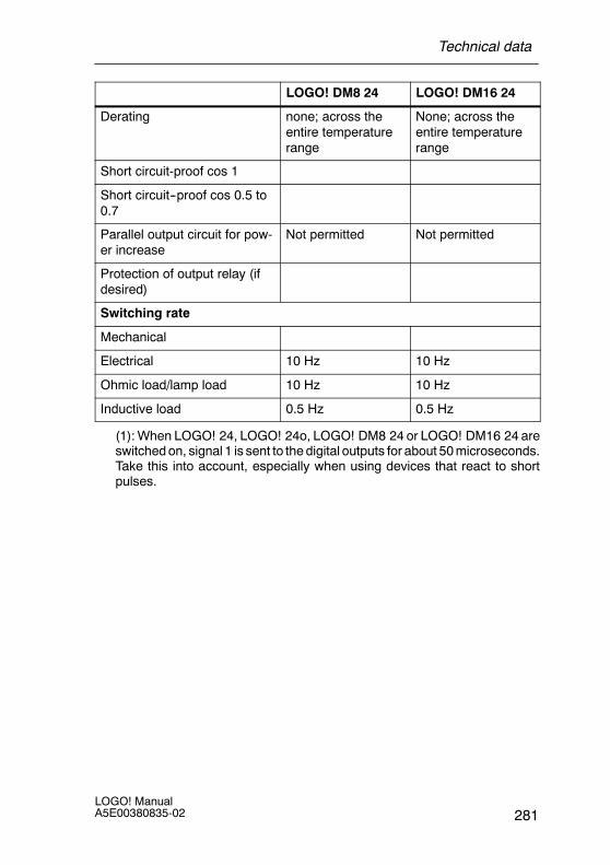
LOGO! DM16 24LOGO! DM8 24
Derating none; across theentire temperaturerange
None; across theentire temperaturerange
Short circuit-proof cos 1
Short circuit--proof cos 0.5 to0.7
Parallel output circuit for pow-er increase
Not permitted Not permitted
Protection of output relay (ifdesired)
Switching rate
Mechanical
Electrical 10 Hz 10 Hz
Ohmic load/lamp load 10 Hz 10 Hz
Inductive load 0.5 Hz 0.5 Hz
(1): When LOGO! 24, LOGO! 24o, LOGO! DM8 24 or LOGO! DM16 24 areswitched on, signal 1 is sent to the digital outputs for about 50 microseconds.Take this into account, especially when using devices that react to shortpulses.
Technical data
LOGO! ManualA5E00380835-02282
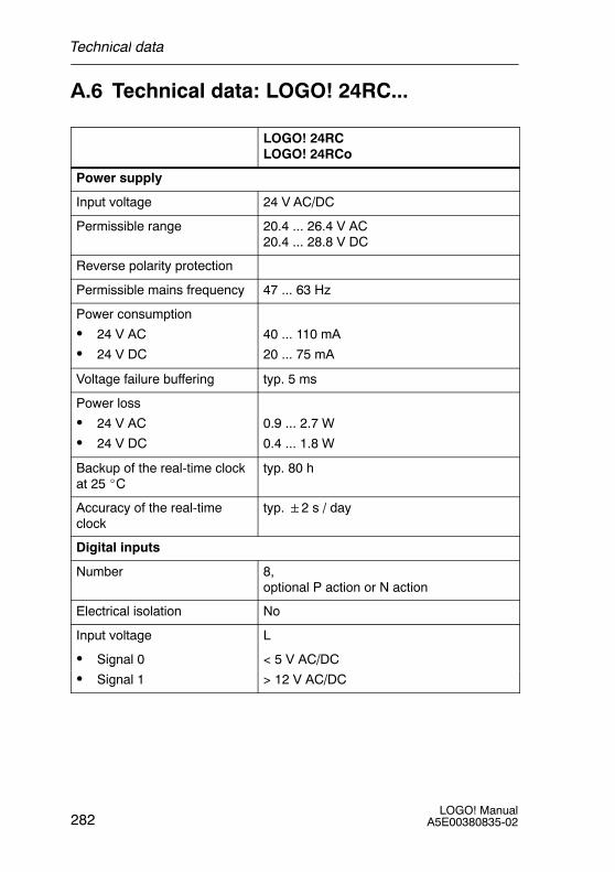
A.6 Technical data: LOGO! 24RC...
LOGO! 24RCLOGO! 24RCo
Power supply
Input voltage 24 V AC/DC
Permissible range 20.4 ... 26.4 V AC20.4 ... 28.8 V DC
Reverse polarity protection
Permissible mains frequency 47 ... 63 Hz
Power consumption
S 24 V AC
S 24 V DC
40 ... 110 mA
20 ... 75 mA
Voltage failure buffering typ. 5 ms
Power loss
S 24 V AC
S 24 V DC
0.9 ... 2.7 W
0.4 ... 1.8 W
Backup of the real-time clockat 25 _C
typ. 80 h
Accuracy of the real-timeclock
typ.2 s / day
Digital inputs
Number 8,optional P action or N action
Electrical isolation No
Input voltage L
S Signal 0 < 5 V AC/DCg
S Signal 1 > 12 V AC/DC
Technical data

283LOGO! ManualA5E00380835-02
LOGO! 24RCLOGO! 24RCo
Input current at
S Signal 0 < 1.0 mA
S Signal 1 > 2.5 mA
Delay time at
S 0 to 1 typ. 1.5 ms
S 1 to 0 typ. 15 ms
Line length (unshielded) 100 m
Analog inputs
Number
Range
max. Input voltage
Digital outputs
Number 4
Output type Relay outputs
Electrical isolation Yes
In groups of 1
Control of a digital input Yes
Output voltage
Output current
Continuous current Ith max. 10 A per relay
Surge current max. 30 A
Incandescent lamp load(25000 switching cycles) at
1000 W
Fluorescent tubes with ballast(25000 switching cycles)
10 x 58 W
Technical data
LOGO! ManualA5E00380835-02284
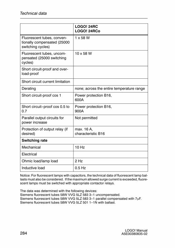
LOGO! 24RCLOGO! 24RCo
Fluorescent tubes, conven-tionally compensated (25000switching cycles)
1 x 58 W
Fluorescent tubes, uncom-pensated (25000 switchingcycles)
10 x 58 W
Short circuit-proof and over-load-proof
Short circuit current limitation
Derating none; across the entire temperature range
Short circuit-proof cos 1 Power protection B16,600A
Short circuit--proof cos 0.5 to0.7
Power protection B16,900A
Parallel output circuits forpower increase
Not permitted
Protection of output relay (ifdesired)
max. 16 A,characteristic B16
Switching rate
Mechanical 10 Hz
Electrical
Ohmic load/lamp load 2 Hz
Inductive load 0.5 Hz
Notice: For fluorescent lamps with capacitors, the technical data of fluorescent lamp bal-lasts must also be considered. If the maximum allowed surge current is exceeded, fluore-scent lamps must be switched with appropriate contactor relays.
The data was determined with the following devices:Siemens fluorescent tubes 58W VVG 5LZ 583 3--1 uncompensated.Siemens fluorescent tubes 58W VVG 5LZ 583 3--1 parallel compensated with 7μF.Siemens fluorescent tubes 58W VVG 5LZ 501 1--1N with ballast.
Technical data
285LOGO! ManualA5E00380835-02
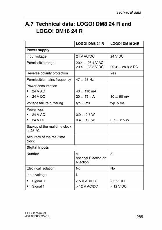
A.7 Technical data: LOGO! DM8 24 R andLOGO! DM16 24 R
LOGO! DM8 24 R LOGO! DM16 24R
Power supply
Input voltage 24 V AC/DC 24 V DC
Permissible range 20.4 ... 26.4 V AC20.4 ... 28.8 V DC 20.4 ... 28.8 V DC
Reverse polarity protection Yes
Permissible mains frequency 47 ... 63 Hz
Power consumption
S 24 V AC
S 24 V DC
40 ... 110 mA
20 ... 75 mA 30 ... 90 mA
Voltage failure buffering typ. 5 ms typ. 5 ms
Power loss
S 24 V AC
S 24 V DC
0.9 ... 2.7 W
0.4 ... 1.8 W 0.7 ... 2.5 W
Backup of the real-time clockat 25 _C
Accuracy of the real-timeclock
Digital inputs
Number 4,optional P action orN action
8
Electrical isolation No No
Input voltage L
S Signal 0 < 5 V AC/DC < 5 V DCg
S Signal 1 > 12 V AC/DC > 12 V DC
Technical data
LOGO! ManualA5E00380835-02286
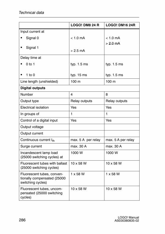
LOGO! DM16 24RLOGO! DM8 24 R
Input current at
S Signal 0 < 1.0 mA < 1.0 mA
> 2.0 mAS Signal 1
> 2.5 mA
> 2.0 mA
Delay time at
S 0 to 1 typ. 1.5 ms typ. 1.5 ms
S 1 to 0 typ. 15 ms typ. 1.5 ms
Line length (unshielded) 100 m 100 m
Digital outputs
Number 4 8
Output type Relay outputs Relay outputs
Electrical isolation Yes Yes
In groups of 1 1
Control of a digital input Yes Yes
Output voltage
Output current
Continuous current Ith max. 5 A per relay max. 5 A per relay
Surge current max. 30 A max. 30 A
Incandescent lamp load(25000 switching cycles) at
1000 W 1000 W
Fluorescent tubes with ballast(25000 switching cycles)
10 x 58 W 10 x 58 W
Fluorescent tubes, conven-tionally compensated (25000switching cycles)
1 x 58 W 1 x 58 W
Fluorescent tubes, uncom-pensated (25000 switchingcycles)
10 x 58 W 10 x 58 W
Technical data
287LOGO! ManualA5E00380835-02
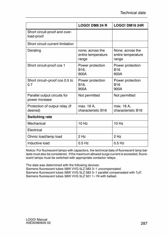
LOGO! DM16 24RLOGO! DM8 24 R
Short circuit-proof and over-load-proof
Short circuit current limitation
Derating none; across theentire temperaturerange
None; across theentire temperaturerange
Short circuit-proof cos 1 Power protectionB16,600A
Power protectionB16600A
Short circuit--proof cos 0.5 to0.7
Power protectionB16,900A
Power protectionB16900A
Parallel output circuits forpower increase
Not permitted Not permitted
Protection of output relay (ifdesired)
max. 16 A,characteristic B16
max. 16 A,characteristic B16
Switching rate
Mechanical 10 Hz 10 Hz
Electrical
Ohmic load/lamp load 2 Hz 2 Hz
Inductive load 0.5 Hz 0.5 Hz
Notice: For fluorescent lamps with capacitors, the technical data of fluorescent lamp bal-lasts must also be considered. If the maximum allowed surge current is exceeded, fluore-scent lamps must be switched with appropriate contactor relays.
The data was determined with the following devices:Siemens fluorescent tubes 58W VVG 5LZ 583 3--1 uncompensated.Siemens fluorescent tubes 58W VVG 5LZ 583 3--1 parallel compensated with 7μF.Siemens fluorescent tubes 58W VVG 5LZ 501 1--1N with ballast.
Technical data
LOGO! ManualA5E00380835-02288
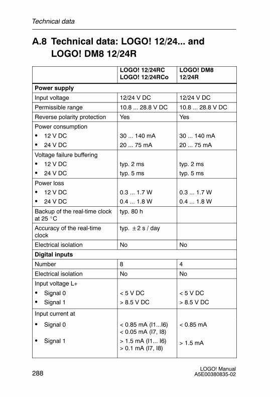
A.8 Technical data: LOGO! 12/24... andLOGO! DM8 12/24R
LOGO! 12/24RCLOGO! 12/24RCo
LOGO! DM812/24R
Power supply
Input voltage 12/24 V DC 12/24 V DC
Permissible range 10.8 ... 28.8 V DC 10.8 ... 28.8 V DC
Reverse polarity protection Yes Yes
Power consumption
S 12 V DC
S 24 V DC
30 ... 140 mA
20 ... 75 mA
30 ... 140 mA
20 ... 75 mA
Voltage failure buffering
S 12 V DC
S 24 V DC
typ. 2 ms
typ. 5 ms
typ. 2 ms
typ. 5 ms
Power loss
S 12 V DC
S 24 V DC
0.3 ... 1.7 W
0.4 ... 1.8 W
0.3 ... 1.7 W
0.4 ... 1.8 W
Backup of the real-time clockat 25 _C
typ. 80 h
Accuracy of the real-timeclock
typ.2 s / day
Electrical isolation No No
Digital inputs
Number 8 4
Electrical isolation No No
Input voltage L+
S Signal 0 < 5 V DC < 5 V DCg
S Signal 1 > 8.5 V DC > 8.5 V DC
Input current at
S Signal 0
Si l
< 0.85 mA (I1...I6)< 0.05 mA (I7, I8)
A (I I )
< 0.85 mA
S Signal 1 > 1.5 mA (I1... I6)> 0.1 mA (I7, I8)
> 1.5 mA
Technical data
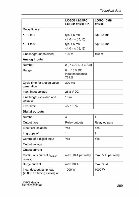
289LOGO! ManualA5E00380835-02
LOGO! DM812/24R
LOGO! 12/24RCLOGO! 12/24RCo
Delay time at
S 0 to 1 typ. 1.5 ms
<1.0 ms (I5, I6)
typ. 1.5 ms
S 1 to 0
( , )
typ. 1.5 ms
<1.0 ms (I5, I6)
typ. 1.5 ms
Line length (unshielded) 100 m 100 m
Analog inputs
Number 2 (I7 = AI1, I8 = AI2)
Range 0 ... 10 V DCinput impedance76 kΩ
Cycle time for analog valuegeneration
300 ms
max. Input voltage 28.8 V DC
Line length (shielded andtwisted)
10 m
Error limit +/-- 1.5 %
Digital outputs
Number 4 4
Output type Relay outputs Relay outputs
Electrical isolation Yes Yes
In groups of 1 1
Control of a digital input Yes Yes
Output voltage
Output current
Continuous current Ith (per
terminal)
max. 10 A per relay max. 5 A per relay
Surge current max. 30 A max. 30 A
Incandescent lamp load(25000 switching cycles) at
1000 W 1000 W
Technical data
LOGO! ManualA5E00380835-02290
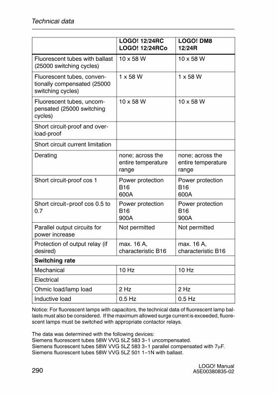
LOGO! DM812/24R
LOGO! 12/24RCLOGO! 12/24RCo
Fluorescent tubes with ballast(25000 switching cycles)
10 x 58 W 10 x 58 W
Fluorescent tubes, conven-tionally compensated (25000switching cycles)
1 x 58 W 1 x 58 W
Fluorescent tubes, uncom-pensated (25000 switchingcycles)
10 x 58 W 10 x 58 W
Short circuit-proof and over-load-proof
Short circuit current limitation
Derating none; across theentire temperaturerange
none; across theentire temperaturerange
Short circuit-proof cos 1 Power protectionB16600A
Power protectionB16600A
Short circuit--proof cos 0.5 to0.7
Power protectionB16900A
Power protectionB16900A
Parallel output circuits forpower increase
Not permitted Not permitted
Protection of output relay (ifdesired)
max. 16 A,characteristic B16
max. 16 A,characteristic B16
Switching rate
Mechanical 10 Hz 10 Hz
Electrical
Ohmic load/lamp load 2 Hz 2 Hz
Inductive load 0.5 Hz 0.5 Hz
Notice: For fluorescent lamps with capacitors, the technical data of fluorescent lamp bal-lasts must also be considered. If the maximum allowed surge current is exceeded, fluore-scent lamps must be switched with appropriate contactor relays.
The data was determined with the following devices:Siemens fluorescent tubes 58W VVG 5LZ 583 3--1 uncompensated.Siemens fluorescent tubes 58W VVG 5LZ 583 3--1 parallel compensated with 7μF.Siemens fluorescent tubes 58W VVG 5LZ 501 1--1N with ballast.
Technical data
291LOGO! ManualA5E00380835-02
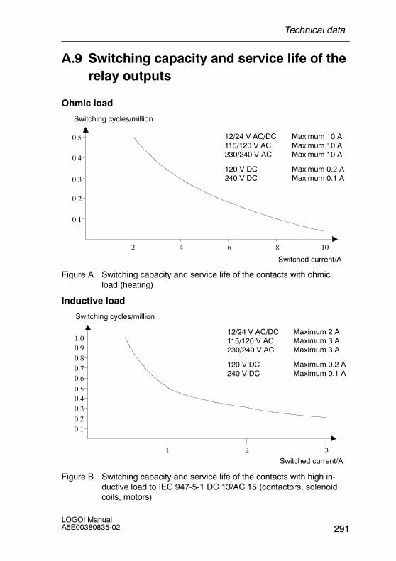
A.9 Switching capacity and service life of therelay outputs
Ohmic load
Switching cycles/million
Switched current/A
0.1
0.2
0.3
0.4
0.5
2 4 6 8 10
Maximum 10 AMaximum 10 AMaximum 10 A
Maximum 0.2 AMaximum 0.1 A
12/24 V AC/DC115/120 V AC230/240 V AC
120 V DC240 V DC
Figure A Switching capacity and service life of the contacts with ohmicload (heating)
Inductive load
Switching cycles/million
Switched current/A
0.10.20.30.40.5
321
0.60.70.80.91.0
Maximum 2 AMaximum 3 AMaximum 3 A
Maximum 0.2 AMaximum 0.1 A
12/24 V AC/DC115/120 V AC230/240 V AC
120 V DC240 V DC
Figure B Switching capacity and service life of the contacts with high in-ductive load to IEC 947-5-1 DC 13/AC 15 (contactors, solenoidcoils, motors)
Technical data
LOGO! ManualA5E00380835-02292
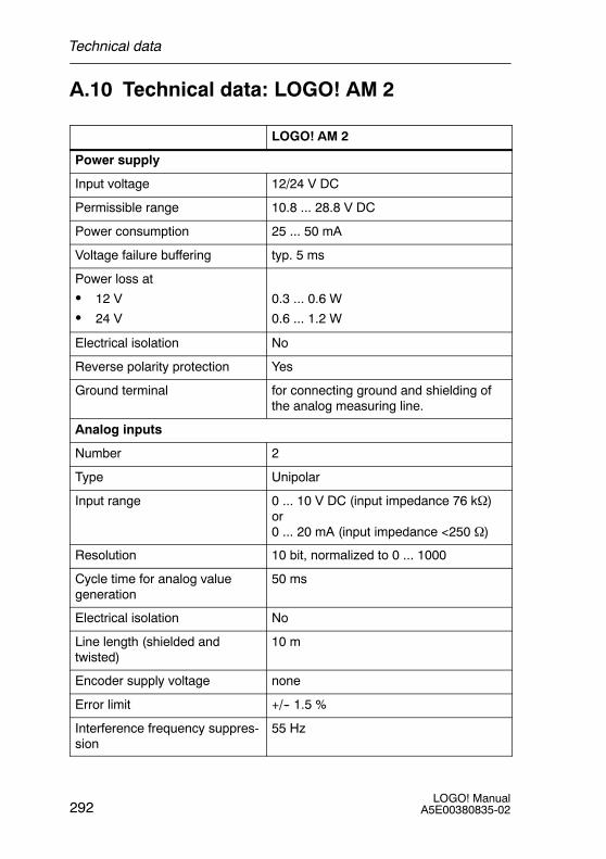
A.10 Technical data: LOGO! AM 2
LOGO! AM 2
Power supply
Input voltage 12/24 V DC
Permissible range 10.8 ... 28.8 V DC
Power consumption 25 ... 50 mA
Voltage failure buffering typ. 5 ms
Power loss at
S 12 V
S 24 V
0.3 ... 0.6 W
0.6 ... 1.2 W
Electrical isolation No
Reverse polarity protection Yes
Ground terminal for connecting ground and shielding ofthe analog measuring line.
Analog inputs
Number 2
Type Unipolar
Input range 0 ... 10 V DC (input impedance 76 kΩ)or0 ... 20 mA (input impedance <250 Ω)
Resolution 10 bit, normalized to 0 ... 1000
Cycle time for analog valuegeneration
50 ms
Electrical isolation No
Line length (shielded andtwisted)
10 m
Encoder supply voltage none
Error limit +/-- 1.5 %
Interference frequency suppres-sion
55 Hz
Technical data
293LOGO! ManualA5E00380835-02
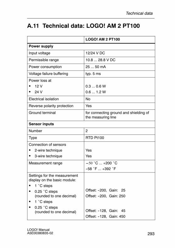
A.11 Technical data: LOGO! AM 2 PT100
LOGO! AM 2 PT100
Power supply
Input voltage 12/24 V DC
Permissible range 10.8 ... 28.8 V DC
Power consumption 25 ... 50 mA
Voltage failure buffering typ. 5 ms
Power loss at
S 12 V
S 24 V
0.3 ... 0.6 W
0.6 ... 1.2 W
Electrical isolation No
Reverse polarity protection Yes
Ground terminal for connecting ground and shielding ofthe measuring line
Sensor inputs
Number 2
Type RTD Pt100
Connection of sensors
S 2-wire technique
S 3-wire technique
Yes
Yes
Measurement range ---50 ˚C ... +200 ˚C--58 ˚F ... +392 ˚F
Settings for the measurementdisplay on the basic module:
S 1 ˚C steps
S 0.25 ˚C steps(rounded to one decimal)
S 1 ˚C steps
S 0.25 ˚C steps(rounded to one decimal)
Offset: --200, Gain: 25
Offset: --200, Gain: 250
Offset: --128, Gain: 45
Offset: --128, Gain: 450
Technical data
LOGO! ManualA5E00380835-02294
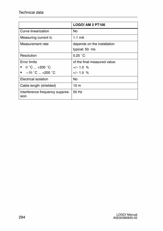
LOGO! AM 2 PT100
Curve linearization No
Measuring current Ic 1.1 mA
Measurement rate depends on the installation
typical: 50 ms
Resolution 0.25 ˚C
Error limits
S 0 ˚C ... +200 ˚CS ---50 ˚C ... +200 ˚C
of the final measured value:
+/-- 1.0 %
+/-- 1.5 %
Electrical isolation No
Cable length (shielded) 10 m
Interference frequency suppres-sion
55 Hz
Technical data
295LOGO! ManualA5E00380835-02
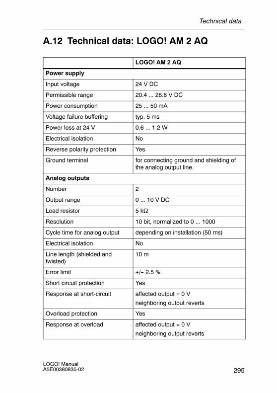
A.12 Technical data: LOGO! AM 2 AQ
LOGO! AM 2 AQ
Power supply
Input voltage 24 V DC
Permissible range 20.4 ... 28.8 V DC
Power consumption 25 ... 50 mA
Voltage failure buffering typ. 5 ms
Power loss at 24 V 0.6 ... 1.2 W
Electrical isolation No
Reverse polarity protection Yes
Ground terminal for connecting ground and shielding ofthe analog output line.
Analog outputs
Number 2
Output range 0 ... 10 V DC
Load resistor 5 kΩ
Resolution 10 bit, normalized to 0 ... 1000
Cycle time for analog output depending on installation (50 ms)
Electrical isolation No
Line length (shielded andtwisted)
10 m
Error limit +/-- 2.5 %
Short circuit protection Yes
Response at short-circuit affected output = 0 V
neighboring output reverts
Overload protection Yes
Response at overload affected output = 0 V
neighboring output reverts
Technical data
LOGO! ManualA5E00380835-02296
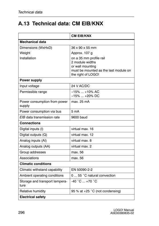
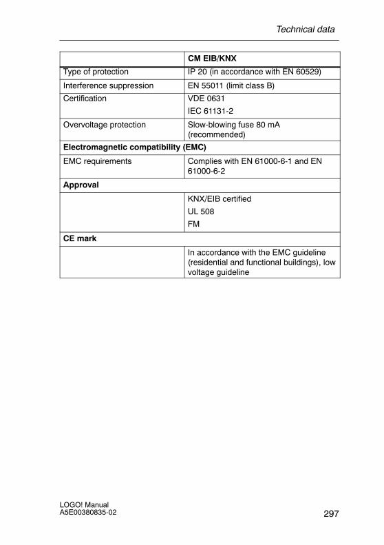
A.13 Technical data: CM EIB/KNX
CM EIB/KNX
Mechanical data
Dimensions (WxHxD)
Weight
Installation
36 x 90 x 55 mm
Approx. 107 g
on a 35 mm profile rail2 module widthsor wall mountingmust be mounted as the last module onthe right of LOGO!
Power supply
Input voltage 24 V AC/DC
Permissible range --15% ... +10% AC--15% ... +20% DC
Power consumption from powersupply
max. 25 mA
Power consumption via bus 5 mA
EIB data transmission rate 9600 baud
Connections
Digital inputs (I) virtual max. 16
Digital outputs (Q) virtual max. 12
Analog inputs (AI) virtual max. 8
Analog outputs (AA) virtual max. 2
Group addresses max. 56
Associations max. 56
Climatic conditions
Climatic withstand capability EN 50090-2-2
Ambient operating conditions 0 ... 55 ˚C natural convection
Storage and transport tempera-ture
-40 ˚C ... +70 ˚C
Relative humidity 95 % at +25 ˚C (not condensing)
Electrical safety
Technical data
297LOGO! ManualA5E00380835-02
CM EIB/KNX
Type of protection IP 20 (in accordance with EN 60529)
Interference suppression EN 55011 (limit class B)
Certification VDE 0631
IEC 61131-2
Overvoltage protection Slow-blowing fuse 80 mA(recommended)
Electromagnetic compatibility (EMC)
EMC requirements Complies with EN 61000-6-1 and EN61000-6-2
Approval
KNX/EIB certified
UL 508
FM
CE mark
In accordance with the EMC guideline(residential and functional buildings), lowvoltage guideline
Technical data
LOGO! ManualA5E00380835-02298
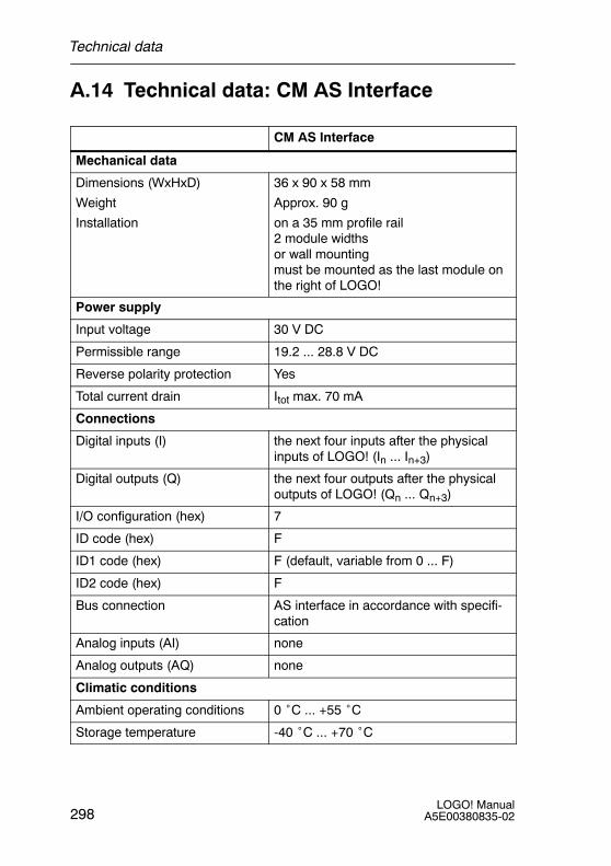
A.14 Technical data: CM AS Interface
CM AS Interface
Mechanical data
Dimensions (WxHxD)
Weight
Installation
36 x 90 x 58 mm
Approx. 90 g
on a 35 mm profile rail2 module widthsor wall mountingmust be mounted as the last module onthe right of LOGO!
Power supply
Input voltage 30 V DC
Permissible range 19.2 ... 28.8 V DC
Reverse polarity protection Yes
Total current drain Itot max. 70 mA
Connections
Digital inputs (I) the next four inputs after the physicalinputs of LOGO! (In ... In+3)
Digital outputs (Q) the next four outputs after the physicaloutputs of LOGO! (Qn ... Qn+3)
I/O configuration (hex) 7
ID code (hex) F
ID1 code (hex) F (default, variable from 0 ... F)
ID2 code (hex) F
Bus connection AS interface in accordance with specifi-cation
Analog inputs (AI) none
Analog outputs (AQ) none
Climatic conditions
Ambient operating conditions 0 ˚C ... +55 ˚C
Storage temperature -40 ˚C ... +70 ˚C
Technical data
299LOGO! ManualA5E00380835-02
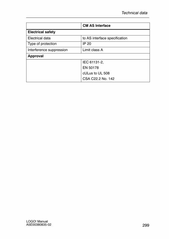
CM AS Interface
Electrical safety
Electrical data to AS interface specification
Type of protection IP 20
Interference suppression Limit class A
Approval
IEC 61131-2,
EN 50178
cULus to UL 508
CSA C22.2 No. 142
Technical data

LOGO! ManualA5E00380835-02300
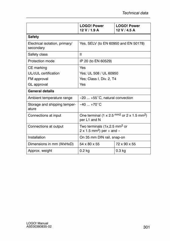
A.15 Technical data: LOGO!Power 12 V
LOGO! Power 12 V is a primary-switched power supply unitfor LOGO! devices. Two current ranges are available.
LOGO! Power12 V / 1.9 A
LOGO! Power12 V / 4.5 A
Input data
Input voltage 100 ... 240 V AC
Permissible range 85 ... 264 V AC
Permissible mains frequency 47 ... 63 Hz
Voltage failure buffering > 40 ms (at 187 V AC)
Input current 0.53 ... 0.3 A 1.13 ... 0.61 A
Make current (25˚C) ≤ 15 A ≤ 30 A
Device protection Internal
Recommended circuit break-er (IEC 898) in mains line
≥ 16 A characteristic B≥ 10 A characteristic C
Output data
Output voltage
Overall tolerance
Adjustment range
Residual ripple
12 V DC
+/--3 %
10.5 ... 16.1 V DC
< 200/300 mVpp
Output current
Overcurrent limiting
1.9 A
typ. 2.5 A
4.5 A
typ. 5.9 A
Efficiency typ. 80 % typ. 85 %
Parallel circuit for power in-crease
Yes
Electromagnetic compatibility
Interference suppression EN 50081-1, Class B to EN 55022
Interference immunity EN 61000-6-2,EN 61000-4-2/-3/-4/-5/-6/-11
Technical data
301LOGO! ManualA5E00380835-02
LOGO! Power12 V / 4.5 A
LOGO! Power12 V / 1.9 A
Safety
Electrical isolation, primary/secondary
Yes, SELV (to EN 60950 and EN 50178)
Safety class II
Protection mode IP 20 (to EN 60529)
CE marking
UL/cUL certification
FM approval
GL approval
Yes
Yes; UL 508 / UL 60950
Yes; Class I, Div. 2, T4
Yes
General details
Ambient temperature range --20 ... +55˚C, natural convection
Storage and shipping temper-ature
--40 ... +70˚C
Connections at input One terminal (1 x 2.5 mm2 or 2 x 1.5 mm2)per L1 and N
Connections at output Two terminals (1x.2.5 mm2 or2 x 1.5 mm2) per + and --
Installation On 35 mm DIN rail, snap-on
Dimensions in mm (WxHxD) 54 x 80 x 55 72 x 90 x 55
Approx. weight 0.2 kg 0.3 kg
Technical data
LOGO! ManualA5E00380835-02302
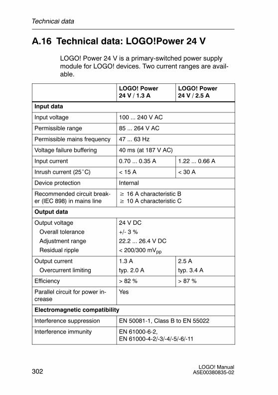
A.16 Technical data: LOGO!Power 24 V
LOGO! Power 24 V is a primary-switched power supplymodule for LOGO! devices. Two current ranges are avail-able.
LOGO! Power24 V / 1.3 A
LOGO! Power24 V / 2.5 A
Input data
Input voltage 100 ... 240 V AC
Permissible range 85 ... 264 V AC
Permissible mains frequency 47 ... 63 Hz
Voltage failure buffering 40 ms (at 187 V AC)
Input current 0.70 ... 0.35 A 1.22 ... 0.66 A
Inrush current (25˚C) < 15 A < 30 A
Device protection Internal
Recommended circuit break-er (IEC 898) in mains line
≥ 16 A characteristic B≥ 10 A characteristic C
Output data
Output voltage
Overall tolerance
Adjustment range
Residual ripple
24 V DC
+/- 3 %
22.2 ... 26.4 V DC
< 200/300 mVpp
Output current
Overcurrent limiting
1.3 A
typ. 2.0 A
2.5 A
typ. 3.4 A
Efficiency > 82 % > 87 %
Parallel circuit for power in-crease
Yes
Electromagnetic compatibility
Interference suppression EN 50081-1, Class B to EN 55022
Interference immunity EN 61000-6-2,EN 61000-4-2/-3/-4/-5/-6/-11
Technical data
303LOGO! ManualA5E00380835-02
LOGO! Power24 V / 2.5 A
LOGO! Power24 V / 1.3 A
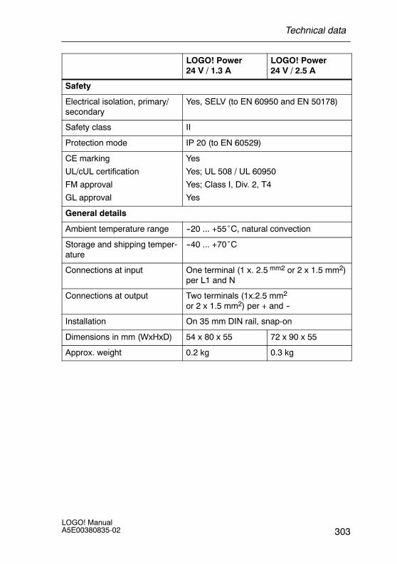
Safety
Electrical isolation, primary/secondary
Yes, SELV (to EN 60950 and EN 50178)
Safety class II
Protection mode IP 20 (to EN 60529)
CE marking
UL/cUL certification
FM approval
GL approval
Yes
Yes; UL 508 / UL 60950
Yes; Class I, Div. 2, T4
Yes
General details
Ambient temperature range --20 ... +55˚C, natural convection
Storage and shipping temper-ature
--40 ... +70˚C
Connections at input One terminal (1 x. 2.5 mm2 or 2 x 1.5 mm2)per L1 and N
Connections at output Two terminals (1x.2.5 mm2
or 2 x 1.5 mm2) per + and --
Installation On 35 mm DIN rail, snap-on
Dimensions in mm (WxHxD) 54 x 80 x 55 72 x 90 x 55
Approx. weight 0.2 kg 0.3 kg
Technical data
LOGO! ManualA5E00380835-02304
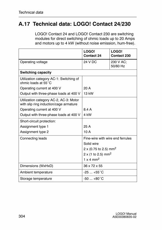
A.17 Technical data: LOGO! Contact 24/230
LOGO! Contact 24 and LOGO! Contact 230 are switchingmodules for direct switching of ohmic loads up to 20 Ampsand motors up to 4 kW (without noise emission, hum-free).
LOGO!Contact 24
LOGO!Contact 230
Operating voltage 24 V DC 230 V AC;50/60 Hz
Switching capacity
Utilization category AC-1: Switching ofohmic loads at 55˚COperating current at 400 V
Output with three-phase loads at 400 V
20 A
13 kW
Utilization category AC-2, AC-3: Motorwith slip ring induction/cage armature
Operating current at 400 V
Output with three-phase loads at 400 V
8.4 A
4 kW
Short-circuit protection:
Assignment type 1
Assignment type 2
25 A
10 A
Connecting leads Fine-wire with wire end ferrules
Solid wire
2 x (0.75 to 2.5) mm2
2 x (1 to 2.5) mm2
1 x 4 mm2
Dimensions (WxHxD) 36 x 72 x 55
Ambient temperature -25 ... +55˚C
Storage temperature -50 ... +80˚C
Technical data