Embed Size (px)
Citation preview

A TACTILE DEVICE FOR THE BLINDBy Sameer Kamath
December Fair Poster
Massachusetts Academy of Math and Science

ENGINEERING PROBLEM
• There are no affordable, widespread, modern electronic travel aids on the market that allow blind people to fully grasp the 3D space in front of them and avoid obstacles.
ENGINEERING GOALS
• The goal of this project is to engineer a tactile device that will allow blind people to perceive and avoid walls, inclines, and obstacles below the waist. The final device must be able to notify a person quickly enough so that he or she can recognize and completely avoid such obstacles.
PURPOSE
• Go beyond what a cane provides
• Give a person a tactile “image” of the 3-D space
• Experiment with modern sensor technology
• Lay out the groundwork for a final device that is:
• Widespread/accessible, practical, useful/accurate
CURRENT ASSISTIVE DEVICES
• Red and white cane
• Too high of an angle between cane and user
• Lots of missed obstacles
• Sweeping side to side results in missed information
• Guide dogs
• Often cost $40,000+ to train
• Need more adequate way to replace depth perception
• Map out space in front of person
• Transfer more precise information to blind person
ELECTRONIC TRAVEL AIDS
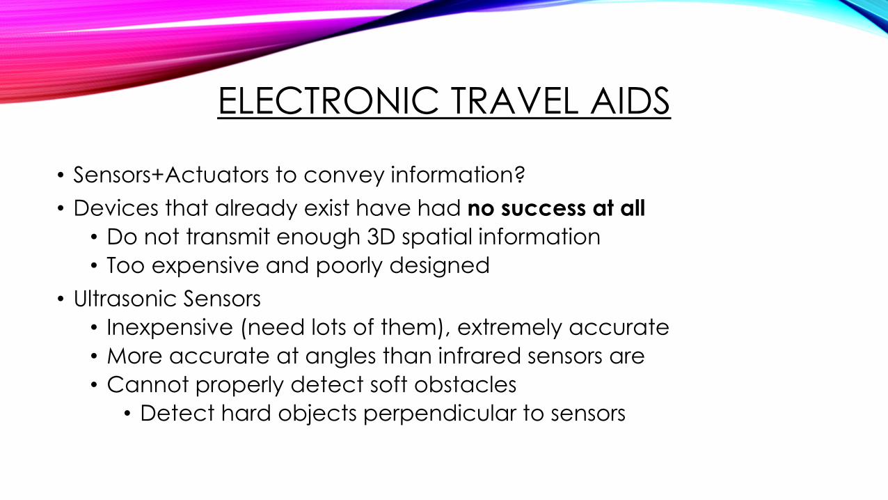
• Sensors+Actuators to convey information?
• Devices that already exist have had no success at all
• Do not transmit enough 3D spatial information
• Too expensive and poorly designed
• Ultrasonic Sensors
• Inexpensive (need lots of them), extremely accurate
• More accurate at angles than infrared sensors are
• Cannot properly detect soft obstacles
• Detect hard objects perpendicular to sensors
ACCURACY TESTING
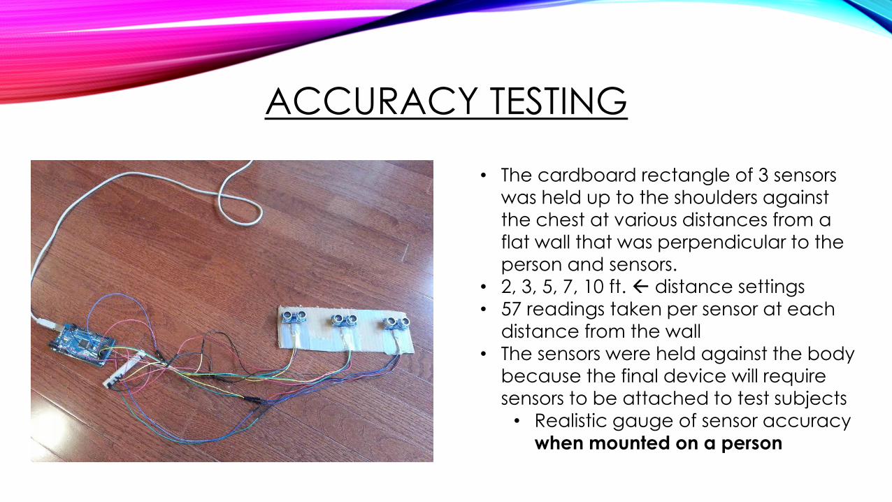
• The cardboard rectangle of 3 sensors
was held up to the shoulders against the chest at various distances from a
flat wall that was perpendicular to the
person and sensors.• 2, 3, 5, 7, 10 ft. distance settings
• 57 readings taken per sensor at each
distance from the wall
• The sensors were held against the body
because the final device will require
sensors to be attached to test subjects
• Realistic gauge of sensor accuracy
when mounted on a person
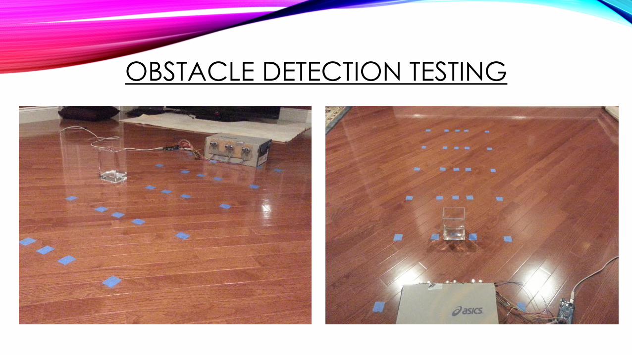
OBSTACLE DETECTION TESTING
RESULTS
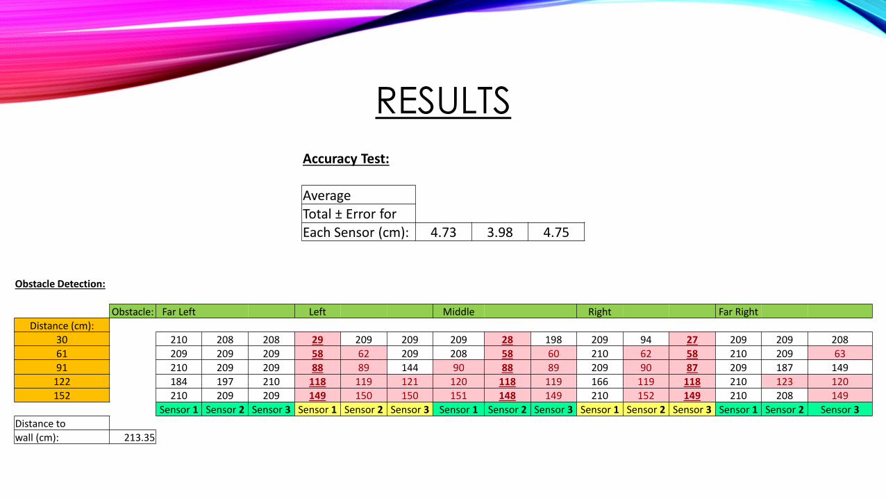
Accuracy Test:
Average Total ± Error for Each Sensor (cm): 4.73 3.98 4.75
Obstacle Detection:
Obstacle: Far Left Left Middle Right Far Right
Distance (cm):
30 210 208 208 29 209 209 209 28 198 209 94 27 209 209 208
61 209 209 209 58 62 209 208 58 60 210 62 58 210 209 63
91 210 209 209 88 89 144 90 88 89 209 90 87 209 187 149
122 184 197 210 118 119 121 120 118 119 166 119 118 210 123 120
152 210 209 209 149 150 150 151 148 149 210 152 149 210 208 149
Sensor 1 Sensor 2 Sensor 3 Sensor 1 Sensor 2 Sensor 3 Sensor 1 Sensor 2 Sensor 3 Sensor 1 Sensor 2 Sensor 3 Sensor 1 Sensor 2 Sensor 3
Distance to
wall (cm): 213.35
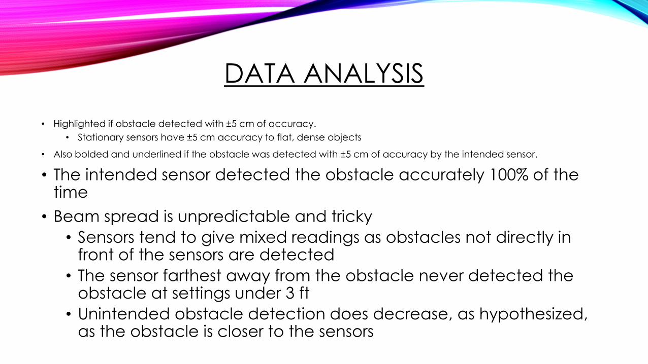
DATA ANALYSIS
• Highlighted if obstacle detected with ±5 cm of accuracy.
• Stationary sensors have ±5 cm accuracy to flat, dense objects
• Also bolded and underlined if the obstacle was detected with ±5 cm of accuracy by the intended sensor.
• The intended sensor detected the obstacle accurately 100% of the time
• Beam spread is unpredictable and tricky
• Sensors tend to give mixed readings as obstacles not directly in front of the sensors are detected
• The sensor farthest away from the obstacle never detected the obstacle at settings under 3 ft
• Unintended obstacle detection does decrease, as hypothesized, as the obstacle is closer to the sensors

DESIGN CRITERIA
• Low Cost
• High Obstacle Avoidance
• High Practicality
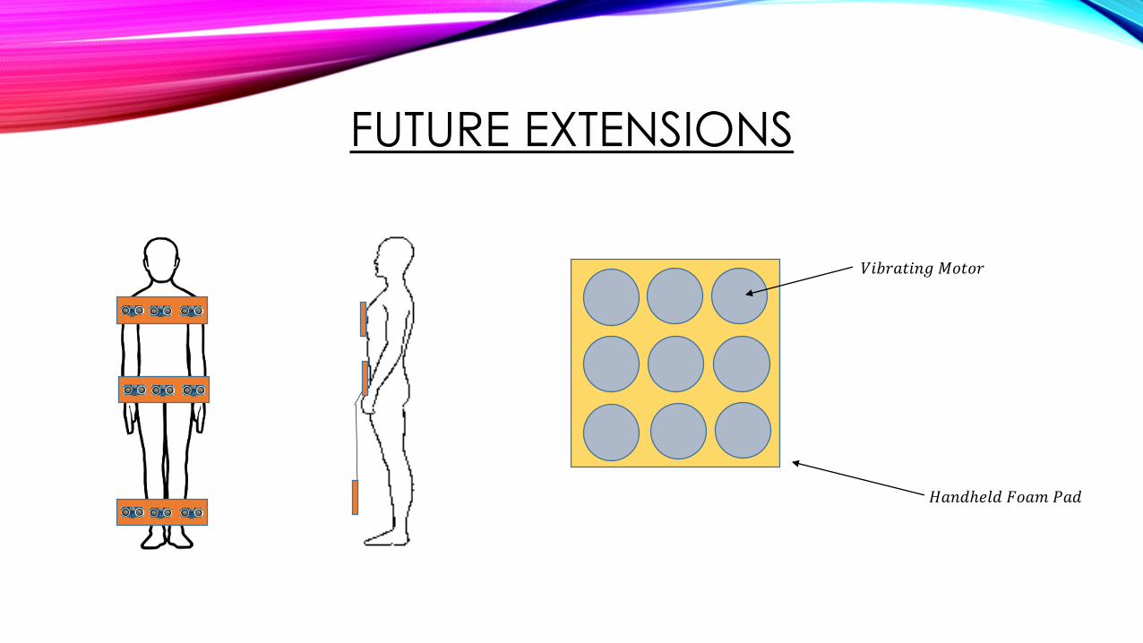
FUTURE EXTENSIONS
𝑉𝑖𝑏𝑟𝑎𝑡𝑖𝑛𝑔 𝑀𝑜𝑡𝑜𝑟
𝐻𝑎𝑛𝑑ℎ𝑒𝑙𝑑 𝐹𝑜𝑎𝑚 𝑃𝑎𝑑
TIMELINE
1. Assemble and test final prototype over December Break
2. Test obstacle detection by traversing an obstacle course while blindfolded
3. If necessary, fix prototype and test again for improvement
4. Analyze data based on criteria for cost, practicality, and obstacle avoidance
CLIPART CREDITS
• http://www.clipartkid.com/images/67/human-body-outline-image-clipart-best-QahlIm-clipart.png
• https://www.vectorstock.com/royalty-free-vector/naked-standing-man-vector-659513
• https://electrosome.com/hc-sr04-ultrasonic-sensor-pic/


![[XLS] · Web viewThe Board has renewed appointed Mr. S.N. Kamath as the Managing Director of the Company and Miss Shruti N. Kamath as Wholetime Director. Also Dr. Vibha N. Kamath appointed](https://img.pdfslide.us/doc/110x75/5aba5c507f8b9ad1768b6a34/xls-viewthe-board-has-renewed-appointed-mr-sn-kamath-as-the-managing-director.jpg)