Embed Size (px)
Citation preview

A SYSTEMATIC APPROACH FOR INTEGRATED
PRODUCT, MATERIALS, AND DESIGN-PROCESS
DESIGN
A Thesis Presented to
the Academic Faculty
By
Matthias Messer
In Partial Fulfillment of the Requirements for The Degree of
Doctor of Philosophy in Mechanical Engineering
Georgia Institute of Technology May 2008
A SYSTEMATIC APPROACH FOR INTEGRATED
PRODUCT, MATERIALS, AND DESIGN-PROCESS
DESIGN Approved by: Dr. Janet K. Allen, Advisor GWW School of Mechanical Engineering Georgia Institute of Technology
Dr. Cyrus K. Aidun GWW School of Mechanical Engineering Georgia Institute of Technology
Dr. Benjamin Klein School of Electrical and Computer Engineering Georgia Institute of Technology
Dr. David L. McDowell GWW School of Mechanical Engineering & School of Materials Science and Engineering Georgia Institute of Technology
Dr. Farrokh Mistree GWW School of Mechanical Engineering Georgia Institute of Technology
Dr. Douglas P. Yoder School of Electrical and Computer Engineering Georgia Institute of Technology
Date Approved: Jan 17, 2008

iii
DEDICATION
To Insa
iv
PREFACE
“Scientists investigate that which already is;
engineers create that which has never been.”
Albert Einstein
Facing dynamic demands on limited resources in a global marketplace, a designer’s
goal is to create innovative products while managing complexity and uncertainty.
Therefore, methods and strategies are developed in this dissertation to increase a
designer’s flexibility, i.e., a designer’s ability to respond to known or unkown dynamic
changes in performance requirements. As described in Chapter 1, special emphasis is on
i) concept flexibility, referring to a designer’s ability to generate concepts, and ii) design-
process flexibility, referring to a designer’s ability to manage complexity in design-
processes when exploring concepts. Focus is on the conceptual and early embodiment
design phases because this is the most crucial design stage during which problems are
framed and the vast majority of resources available for product creation is allocated.
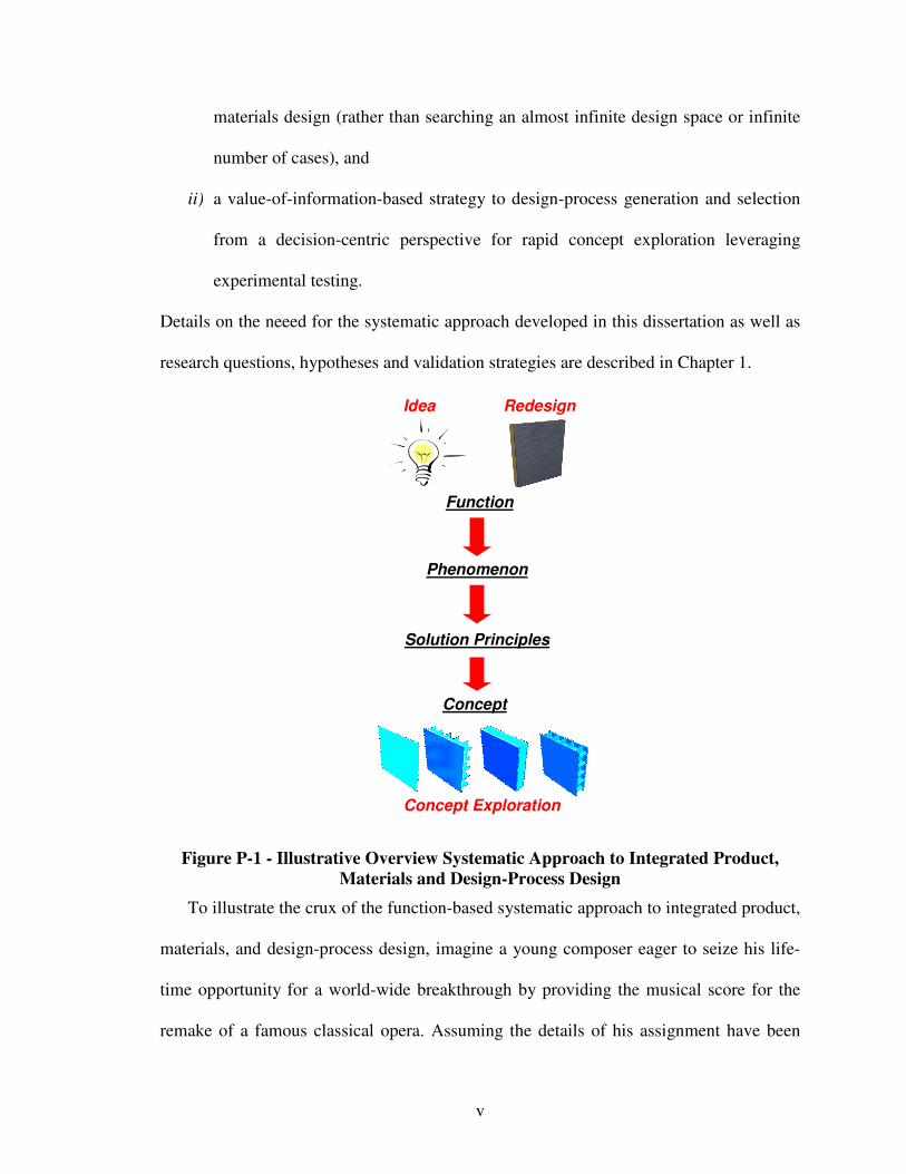
In order to increase a designer’s concept and design-process flexibility, a systematic
approach for integrated product, materials, and design-process design is developed in this
dissertation. As illustrated in Figure P-1, crucial to this problem-directed systematic
approach are:
i) a function-based design method for the integrated design of product and material
concepts leveraging classified materials structure-property relations that drive
v
materials design (rather than searching an almost infinite design space or infinite
number of cases), and
ii) a value-of-information-based strategy to design-process generation and selection
from a decision-centric perspective for rapid concept exploration leveraging
experimental testing.
Details on the neeed for the systematic approach developed in this dissertation as well as
research questions, hypotheses and validation strategies are described in Chapter 1.
Idea Redesign
Function
Phenomenon
Solution Principles
Concept
Concept Exploration
Figure P-1 - Illustrative Overview Systematic Approach to Integrated Product,
Materials and Design-Process Design
To illustrate the crux of the function-based systematic approach to integrated product,
materials, and design-process design, imagine a young composer eager to seize his life-
time opportunity for a world-wide breakthrough by providing the musical score for the
remake of a famous classical opera. Assuming the details of his assignment have been
vi
clarified, his first step from a problem-directed perspective is to frame his assignment in
terms of functions his music should convey in solution-neutral terms. Obviously, the core
function is to “provide music” in high quality. However, since he only has limited time
and prefers to master his breakthrough with certainty, he considers the following
potential solutions to provide high-quality music:
i) selecting well-known and established pieces, as illustrated in Figure P-2 a),
ii) assembling and grouping an orchestra and chorus to perform pieces, as illustrated
in Figure P-2 b),
iii) assembling and grouping an orchestra and chorus as well as creating sequences of
compositions for specific instruments and vocal tones, as illustrated in Figure P-2
c), or
iv) assembling and grouping an orchestra and chorus as well as creating
compositions measure by measure or note by note, as illustrated in Figure P-2 d).
From the problem-directed design perspective taken in this dissertation, functions are
used to describe, in a solution-neutral fashion, idealized behavior of a product or system
that is required to solve a clarified design problem, such as “provide music” in the
illustrative example. However, often, a designer has to deal with multiple required
functions. Hence, functions can be added, even neglected, or combined in different ways
to yield a variety of potential solutions to an initial problem. For example, the young
composer may not only consider the function “provide music”, but also “provide video”
or “provide refreshments” to increase his chances of a breakthrough.
Having developed different abstract product or system representations on a functional
level, a designer must find means to fulfill the specified functionality. In the context of
vii
the illustrative example, the composer has already identified various means, such as audio
records, artists, instruments, etc. In the function-based systematic approach developed in
this dissertation, those means are referred to as phenomena, i.e., fundamental means that
can be described quantitatively by laws of physics and mathematics, such as inertia
described by Newton’s law. However, a phenomenon represents only a very abstract
description of the solution fulfilling a specific function. Hence, solution principles
associated with a specific phenomenon, i.e., physical instantiations to realize a specific
phenomenon, are identified.
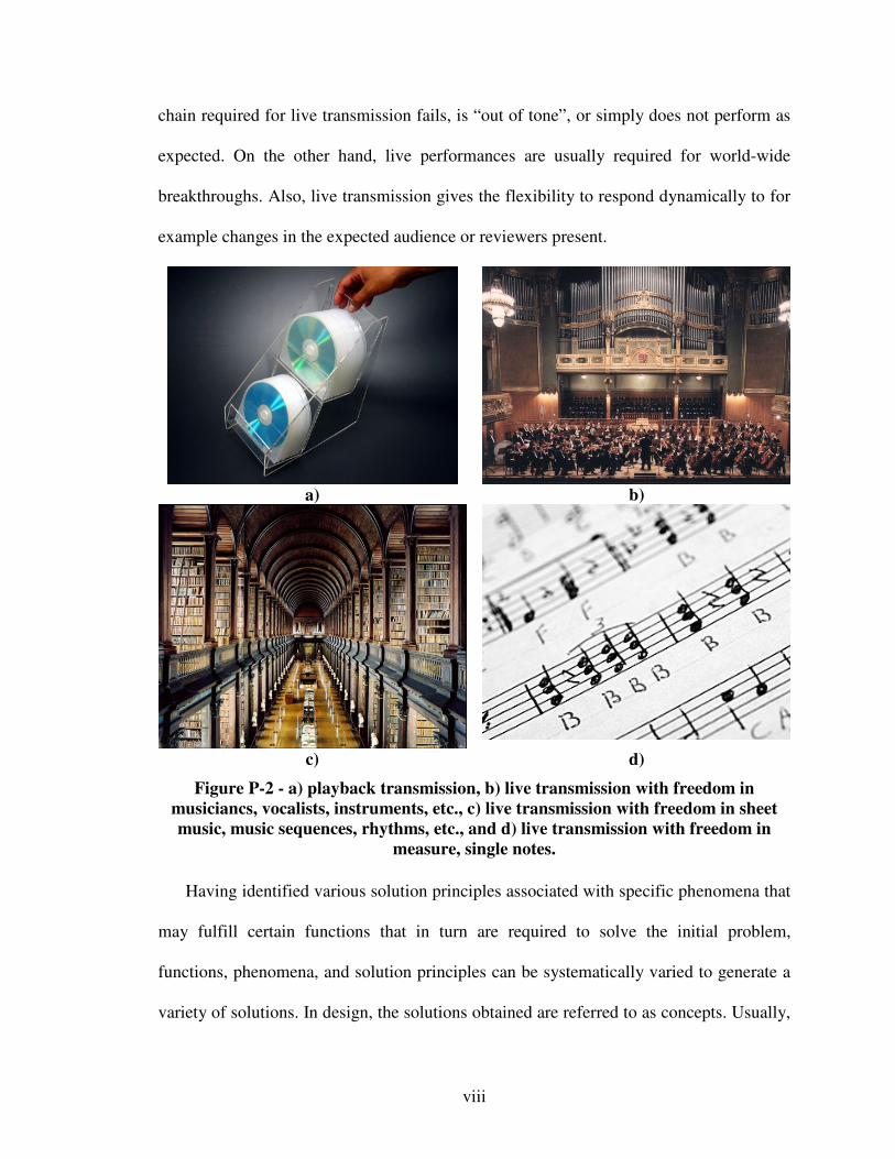
In the context of the illustrative example, phenomena would correspond to playback
transmission, i.e., using audio records to provide music, or live transmission, i.e., using
artists to provide music. Then, solution principles for playback transmission include CDs,
LPs, tapes, mp3files, etc. Solution principles for live transmission include i) various
musicians, vocalists, instruments, etc. on a larger scale, ii) sheet music, music sequences,
rhythms, etc. on a smaller scale, or iii) measure, single notes, etc. on an even smaller
scale. Obviously, depending on the solution principles on a specific scale that the
composer leverages to synthesize his composition, his assignment will become more and
more complex, but, easier to customize.
On a small scale, essentially writing a custom-made composition note by note, his
assignment will become most complex, but, he has ultimate freedom to express himself
and achieve the requirements for his breakthrough. On the other hand, selecting playback
transmission, high-quality music is almost guaranteed with certainty while making his
assignment as simple as it can get. Hence, he would not need to worry about the rather
extensive uncertainty that one element (instrument, musician, vocalist, etc.) in the long
viii
chain required for live transmission fails, is “out of tone”, or simply does not perform as
expected. On the other hand, live performances are usually required for world-wide
breakthroughs. Also, live transmission gives the flexibility to respond dynamically to for
example changes in the expected audience or reviewers present.
a) b)
c) d)
Figure P-2 - a) playback transmission, b) live transmission with freedom in
musiciancs, vocalists, instruments, etc., c) live transmission with freedom in sheet
music, music sequences, rhythms, etc., and d) live transmission with freedom in
measure, single notes.
Having identified various solution principles associated with specific phenomena that
may fulfill certain functions that in turn are required to solve the initial problem,
functions, phenomena, and solution principles can be systematically varied to generate a
variety of solutions. In design, the solutions obtained are referred to as concepts. Usually,
ix
out of a variety of concepts generated and explored, one concept, i.e., a principal solution,
is selected to be further embodied as the solution to the initial problem. Being the young
composer, his dilemma is: What are the functions, phenomena, and solution principles he
uses to compose (synthesize) his breakthrough concept? To facilitate finding a solution to
this problem, design catalogs are developed in this dissertation. In the context of the
illustrative example, these design catalogs are used to classify phenomena and solution
principles, such as CDs, instruments, sheet music, single notes, ect. on various scales,
from whose combinations many solution can be derived with ease.
As described in Chapter 1, it has been shown, that designing concepts is the most
crucial design activity. Hence, focus in this dissertation is on developing a function-based
systematic approach to the integrated design of product and material concepts and
associated embodiment design-processes. Integrating the design of material with product
concepts increases a designer’s flexibility when generating concepts, by for example
leveraging materials structure-property relations classified in design catalgos to create
innovative products. In the context of the illustrative example, materials structure-
property relations are solution principles on various scales, such as atomic elements on a
smaller scale correspond to single notes, cellular mesostructures correspond to certain
musical sequences, etc.
Also, integrating the design of material and product concepts turns materials design
more into designing rather than automatically searching through an almost infinite design
space or infinite number of cases. In the context of the illustrative example, an analogy
would be to not only consider the synthesis of single notes to a symphony, but also the
synthesis of musical measures, instruments, vocalists, etc., i.e., solution principles on
x
various scales to achieve desired performance and thereby narrow the nearly infinite
solution space provided through the synthesis of single notes. In this context, design
catalogs provide a classified collection of phenomena and associated solution principles
to help a young composer achieving desired performance.
However, since exploring integrated product and material concepts that leverage
small scale solution principles through embodiment design-processes is mostly tedious, a
systematic strategy to design-process generation and selection is also developed in this
dissertation, as summarized in Chapter 1 and described in greater detail in Chapter 5. In
the context of the illustrative example, this refers to the question of which means are best
suited to for example compose music, once it has been decided how the concept of the
musical scale is going to be.
In Chapter 2, theoretical foundations based on which the systematic approach to
integrated product, materials, and design-process deisgn is developed are introduced and
reviewed. Besides the underlying decision-centric design philosophy, systems and
materials design philosophies, as well as methods and tools to increase a designer’s
flexibility are reviewed and critically evaluated. Methods and tools to increase a
designer’s concept flexibility for example include systematic as well as general solution
finding methods, such as brainstorming, morphological thinking, blockbusting, etc. It is
then argued why the general solution finding methods of analysis, abstraction, synthesis,
and systematic variation, as described in Chapter 2, are leveraged to develop the
function-based systematic approach to the integrated design of product and material
concepts.
xi
The function-based systematic approach to the integrated design of product and
material concepts is illustrated in Figure P-1 and described in detail in Chapter 3. First,
specific function-based and systematic approaches are reviewed and research gaps
identified. Then, theoretical foundations and the systematic mappings for function-based
materials design, multiflevel function structures, and attention-directing concept selection
charts are described. Finally measures of success, i.e., concept flexibility indicators, are
identified as well as limitations and opportunities for future work are discussed along
with verification and validation.
In Chapter 4, design catalogs are developed to facilitate function-based systematic
design of product and material concepts in an integrated fashion. These design catalogs
are focused phenomena and associated solution principles, i.e., root mechanisms to affect
larger scale behavior, not specific cases or material artifacts in order to let a designer step
out of the technological cycle of obsolence and evolution. By operating at the level of
phenomena and associated solution principles, a particular marterial/system at any given
time is thus only illustrative of the possibilities, not their determinant. Having reviewed
various history-based design approaches such as case based reasoning, research gaps are
identified and analyzed. Theoretical foundations of developing design catalogs are
reviewed. Then, an energy-based phenomena design catalog is developed and its
applications exemplified with illustrative examples. Then, a scale-based solution
principles design catalog is developed. Finally, limitations and opportunities of future
work are discussed along with verification and validation.
In Chapter 5, focus shifts to designing design-processes for concept exploration from
a decision-centric perspective. Combining inductive (top-down) engeineering with
xii
deductive (bottom-up) science, a Process Performance Indicator and a generally
applicable design-process generation and selection strategy is developed. Reviewing
existing approaches to design-process design, it becomes obvious that a new value-of-
information-based metric and strategy are required to deal with both, simplifying and
refining interactions as well as analysis models while not being dependent on the
knowledge of a truthful design-process or its (either deterministic or probabilistic)
globally, i.e., throughout the whole design space – crucial for many scenarios of
exploring integrated product and material concepts. Having described the value-of-
information-based Process Performance Indicator and strategy to generate and select
embodiment design-process alternatives, limitations and opportunities for future work are
discussed along with verification and validation.
Having developed the i) function-based systematic approach to the integrated design
of product and material concepts including design catalogs as well as ii) the value-of-
information based Process Performance Indicator and strategy to embodiment design-
process generation and selection, these constructs are synthesized to the systematic
approach to integrated product, materials, and design-process design in Chapter 6.
Describing its applicability for both original and adaptive design, verification and
validation of the systematic approach and its constructs are discussed.
In Chapter 7, the systematic approach is tested as a whole using the comprehensive
example problem of a reactive material containment system. With respect to the reactive
material containment system, the example problem, fundamental modeling, material
property, and loading assumptions are clarified first. Then focus is on applying the
function-based systematic approach to the integrated design of product and material
xiii
concepts and concept exploration to converge to a principal solution. This principal
solution is then used to test the value-of-information Process Performance Indicator and
strategy to embodiment design-process generation and selection. Results are discussed
along with verification and validation.
Having addressed an example problem in the mechanics domain of materials design,
the design of photonic crystal waveguides in the context of a next-generation
optoelectronic communication system is used in Chapter 8 to test the systematic approach
to embodiment design-process design in the electronics domain of materials design. The
example problem and modeling assumptions are first clarified. Then, the value-of-
information-based Process Performance Indicator and strategy to embodiment design-
process generation and selection are applied. Finally results are discussed along with
verification and validation.
In Chapter 9, this dissertation is summarized. Then, research questions are revisited
as well as verification and validation of the research hypotheses are addressed.
Achievements and contributions are summarized along with limitations and opportunities
for future work. Finally, the author’s vision for research in design is addressed, going
beyond the new interpretation to materials structure-property relations and their
classification in design catalogs facilitating conceptual design of material integrated with
products in a new, systematic, function-based way, as addressed in this dissertation.
Matthias Messer
Atlanta, Georgia, U.S.A.
January 2008

xiv
ACKNOWLEDGEMENTS
This dissertation is dedicated to Insa, who has been with me during all ups and downs
of this dissertation and hopefully continues to be with me during all ups and downs on
our way to come. Also, I can never thank my parents and family enough. Without all of
them, I would never have gotten far!
I would like to thank my “design” advisors and mentors, starting with my father,
followed by Drs. Herbert Birkhofer, Rainer Storm, Cyrus Aidun, Janet Allen, Farrokh
Mistree, David McDowell, Douglas Yoder, Benjamin Klein, and Jitesh Panchal. Ever
since my father sat with me at the age of 16 through one 90 minute graduate level lecture
“Produktentwicklung” given by Drs. Herbert Birkhofer and Hermann Kloberdanz at the
Technical University of Darmstadt, I longed to become a designer. As a consequence, I
chose my major fields of study accordingly to obtain the knowledge in the technological,
humanitarian, and social sciences required to design – beginning in the final three year
phase of the German Highschool system, over the unique general program of study
“Allgemeiner Maschinenbau” at the Technical University of Darmstadt, and finally
ending with specialized graduate studies in the Systems Realization Laboratory (SRL) at
the Georgia Institute of Technology (Georgia Tech).
I am indebted to the SRL family, particularly Janet and Farrokh, for helping, trusting,
and supporting my way, as well as standing behind to back up in critical situations.
Together with Drs. David McDowell and Cyrus Aidun, Farrokh, Janet, and Jitesh are the
most motivational and visionary, as well as challenging, orchestrators I have met,

xv
providing each in their own way exceptional learning environments for individuals in a
team-setting, giving everyone the opportunity to grow beyond expectations. Especially, I
want to thank Janet and Farrokh for their enthusiasm and help for me realizing my full
potential by setting high goals and providing support to achieve those goals. Also, I am
grateful for the advice and insight of my Ph.D. committee members that has made my
journey of aspiring integrated product, materials, and process design the theme of my
career at first in industry and then in their footsteps in academia.
I am thankful to the rich, diverse, and challenging culture in the SRL, in the
computational electronics groups headed by Drs. Benjamin Klein and Douglas Yoder, as
well in the international Georgia Tech community. Particularly, I would like to mention
Vivek Krishnamurthy for his patience explaining the details of his codes, Hannah
Muchnik, Gautam Puri, Jin Song, and Stephanie Thompson for the mostly confusing but
finally benefitial time in (re)defining our research in terms of multifunctional blast
resistant panels, as well as Mervyn Fathianathan, Nathan Young, Matthew Chamberlain,
Chris Williams, Marco Fernandez, Benay Sager, Anusha Vekatachalam, and especially
all of the past and new inhabitants of MaRC 264 and EDRB 235 for their support, advice,
and friendship. Last but not least, I especially thank my best friends and Georgia Tech
roommates Dr. Nicolas Gastaud and Kamyar Hazaveh for all the priceless lessons
learned.
Also, I gratefully acknowledge the support from Air Force Office of Scientific
Research (AFOSR) Multi-University Research Initiative Grant on Energetic Structural
Materials (1606U81). I am also grateful for the support and assistance given to me by
The NSF I/UCRC Center for Computational Materials Design, a joint venture between

xvi
The Pennsylvania State University and Georgia Institute of Technology. Also, I very
much thank Dr. David Frost and Farrokh for their advise and support of the GTS-
Colloquium and GTS-Research Symposium efforts initiated.
Furthermore, I very much thank the Colby family, initiating my desire to study in the
U.S.A. and being the support on which I could always count. Moreover, I am grateful for
the honorary organizers of the student exchange program of the Federation of the
Germany American Clubs, particularly Regine Lichtenthaler, Drs. Elisabeth and Sigmar
Wittig, as well as Dr. Carlton Parker from the World Student Fund. Besides bringing me
to Georgia Tech, they have provided now a countless numbers of American and German
students with priceless learning, growth and realization opportunities, thereby faciliting
the cultural exchange and mutual understanding between both nations. Overall, this
dissertation would not have been possible without the immense support I received.
xvii
TABLE OF CONTENTS
DEDICATION............................................................................................................................................ III
PREFACE................................................................................................................................................... IV
ACKNOWLEDGEMENTS.................................................................................................................... XIV
LIST OF TABLES .................................................................................................................................XXII
LIST OF FIGURES ............................................................................................................................... XXV
GLOSSARY...........................................................................................................................................XXXI
SUMMARY......................................................................................................................................XXXVIII
CHAPTER 1 INTEGRATED PRODUCT, MATERIALS AND DESIGN-PROCESS DESIGN .....1
1.1 THE NEED FOR INTEGRATED PRODUCT, MATERIALS, AND DESIGN-PROCESS DESIGN IN THE
EARLY PHASES OF DESIGN ..........................................................................................................................1 1.1.1 On Achieving Concept Flexibility............................................................................................9 1.1.2 Research Efforts in Function-Based Systematic Conceptual Product Design.......................12 1.1.3 Research Efforts in Function-Based Systematic Conceptual Materials Design ....................22 1.1.4 Motivating Integrated design of product and material concepts on multiple levels and scales
from a systems perspective ..................................................................................................................27 1.1.5 On Achieving Design-Process Flexibility..............................................................................33 1.1.6 Motivating Example Problems ..............................................................................................38
1.2 RESEARCH QUESTIONS AND HYPOTHESES ..................................................................................47 1.2.1 Research Gaps and Overview................................................................................................48 1.2.2 Introducing Research Questions and Hypotheses .................................................................49 1.2.3 Research Area 1: Concept Flexibility....................................................................................53 1.2.4 Research Area 2: Design-Process Flexibility........................................................................55 1.2.5 Fundamental Research Assumptions .....................................................................................57 1.2.6 Overview Research Hypotheses.............................................................................................59 1.2.7 Research Contributions .........................................................................................................62
1.3 VALIDATION STRATEGY .............................................................................................................65 1.4 ORGANIZATION OF DISSERTATION ..............................................................................................73
CHAPTER 2 FOUNDATIONS FOR DEVELOPING A SYSTEMATIC APPROACH TO
INTEGRATED DESIGN OF PRODUCTS, MATERIALS AND DESIGN-PROCESSES ..................75
2.1 THEORETICAL FOUNDATIONS USED IN THIS DISSERTATION........................................................78 2.1.1 Design-Process Modeling – a Template-Based Decision-Centric Perspective .....................78 2.1.2 Design of Systems ................................................................................................................109 2.1.3 Design of Materials .............................................................................................................115 2.1.4 Flexibility in Design ............................................................................................................125
2.2 METHODS AND TOOLS TO ACHIEVE CONCEPT FLEXIBILITY......................................................131 2.2.1 Systematic Function-Based Conceptual Design ..................................................................132 2.2.2 Solution Finding Methods ...................................................................................................135 2.2.3 Set-Based Design.................................................................................................................148 2.2.4 Design Principles ................................................................................................................152 2.2.5 Limitations and Use of Methods and Tools for Achieving Concept Flexibility in this
Dissertation........................................................................................................................................155 2.3 METHODS AND TOOLS TO ACHIEVE DESIGN-PROCESS FLEXIBILITY .........................................155
2.3.1 Optimum-Solution-Based Design ........................................................................................157 2.3.2 Interval-Based Design .........................................................................................................159 2.3.3 Game-Based Design ............................................................................................................161
xviii
2.3.4 Metamodel-Based Design....................................................................................................167 2.3.5 Design-Process Design Based on Information Economical Principles...............................171 2.3.6 Limitations and Use of Methods and Tools for Achieving Design-Process Flexibility in this
Dissertation........................................................................................................................................174 2.4 METHODS AND TOOLS TO ACHIEVE PRODUCT FLEXIBILITY .....................................................176
2.4.1 Design for Modularity .........................................................................................................177 2.4.2 Design for Mutability ..........................................................................................................182 2.4.3 Design for Robustness .........................................................................................................184 2.4.4 Combinations – Design for Reconfigurability .....................................................................189 2.4.5 Use of Methods and Tools for Achieving Concept Flexibility in this Dissertation..............190
2.5 ROLE OF CHAPTER 2 IN THIS DISSERTATION .............................................................................190
CHAPTER 3 SYSTEMATIC FUNCTION-BASED APPROACH TO THE INTEGRATED
DESIGN OF PRODUCT AND MATERIAL CONCEPTS ...................................................................193
3.1 FRAME OF REFERENCE – ANSWERING THE RESEARCH QUESTION 1..........................................194 3.2 A LITERATURE REVIEW FUNCTION-BASED SYSTEMATIC CONCEPTUAL DESIGN ......................198
3.2.1 Systematic Conceptual Design ............................................................................................199 3.2.2 Function-Based Design .......................................................................................................203 3.2.3 Function-Based Systematic Conceptual Design ..................................................................211 3.2.4 A Note On Selection.............................................................................................................214 3.2.5 Research Gap Analysis........................................................................................................217
3.3 PROPOSED FUNCTION-BASED SYSTEMATIC DESIGN FOR ORIGINAL DESIGN.............................222 3.3.1 Determining Multilevel Function Structures .......................................................................223 3.3.2 Determining Concepts .........................................................................................................227 3.3.3 Concept Selection and Exploration .....................................................................................230
3.4 CONCEPT FLEXIBILITY INDICATORS..........................................................................................235 3.5 DISCUSSION, LIMITATIONS, AND OPPORTUNITIES FOR FUTURE WORK – FUNCTION-BASED
SYSTEMATIC APPROACH TO THE INTEGRATED DESIGN OF PRODUCT AND MATERIAL CONCEPTS ...........237 3.6 ON VERIFICATION AND VALIDATION – THEORETICAL STRUCTURAL VALIDATION ...................242 3.7 ROLE OF CHAPTER 3 IN THIS DISSERTATION.............................................................................245
CHAPTER 4 INTEGRATED PRODUCT AND MATERIALS DESIGN CATALOGS...............247
4.1 FRAME OF REFERENCE – FACILITATING SYSTEMATIC, FUNCTION-BASED CONCEPTUAL DESIGN
248 4.2 DESIGN CATALOGS AND CASE-BASED REASONING – INTRODUCTION, LITERATURE REVIEW, AND
RESEARCH GAP .......................................................................................................................................251 4.2.1 Bounded Rationality ............................................................................................................253 4.2.2 Case-Based Reasoning ........................................................................................................257 4.2.3 Classification Schemes and Design Catalogs......................................................................259 4.2.4 Research Gap Analysis Case-Based Reasoning and Design Catalogs................................261
4.3 DESIGN CATALOG – PHENOMENA .............................................................................................267 4.3.1 Striction and Rheology ........................................................................................................268 4.3.2 Semi-, and Super-Conductors as well as Meta-Materials ...................................................273 4.3.3 Luminescence, Tropism and Chromism...............................................................................279 4.3.4 Phase-Transformations .......................................................................................................282 4.3.5 Multifunctional Composites, Films, Coatings, and Weaves ................................................284
4.4 DESIGN CATALOG – ASSOCIATED SOLUTION PRINCIPLES .........................................................286 4.5 DISCUSSION, LIMITATIONS AND OPPORTUNITIES FOR FUTURE WORK – DESIGN CATALOGS ....300 4.6 ON VERIFICATION AND VALIDATION – THEORETICAL STRUCTURAL VALIDATION ...................306 4.7 ROLE OF CHAPTER 4 IN THIS DISSERTATION.............................................................................309
CHAPTER 5 SYSTEMATIC VALUE-OF-INFORMATION-BASED STRATEGY TO DESIGN-
PROCESS GENERATION AND SELECTION ....................................................................................311
5.1 FRAME OF REFERENCE – ANSWERING THE RESEARCH QUESTION 2..........................................312 5.2 VALUE OF INFORMATION FOR DECISION MAKING – A LITERATURE REVIEW ...........................317
5.2.1 Systematic Approaches to Managing Uncertainty...............................................................319
xix
5.2.2 Systematic Approach to Managing Complexity...................................................................322 5.2.3 A Note On Model Validation ...............................................................................................327 5.2.4 Managing Complexity Using Value-Of-Information-based Metrics ...................................331 5.2.5 Research Gap Analysis........................................................................................................336
5.3 PROPOSED METRIC FOR VALUE OF INFORMATION FOR DECISION MAKING...............................346 5.3.1 Definition of Process Performance Indicator......................................................................348 5.3.2 Discussion Process Performance Indicator ........................................................................355
5.4 DESIGN-PROCESS GENERATION AND SELECTION STRATEGY ....................................................359 5.5 LIMITATIONS AND OPPORTUNITIES FOR FUTURE WORK ...........................................................366 5.6 ON VERIFICATION AND VALIDATION – THEORETICAL STRUCTURAL VALIDATION ...................369 5.7 ROLE OF CHAPTER 5 IN THIS DISSERTATION.............................................................................371
CHAPTER 6 SYNTHESIZING THE SYSTEMATIC APPROACH TO INTEGRATED DESIGN
OF PRODUCTS, MATERIALS, AND DESIGN-PROCESSES ...........................................................374
6.1 CONTEXT – ANSWERING THE PRIMARY RESEARCH QUESTION .................................................374 6.2 OVERVIEW SYSTEMATIC APPROACH TO THE INTEGRATED DESIGN OF PRODUCTS, MATERIALS, AND DESIGN-PROCESSES.........................................................................................................................376
6.2.1 Synthesizing the Systematic Approach to the Integrated Design of Products, Materials, and
Design-Processes...............................................................................................................................376 6.2.2 Step 0 – Design Problem Clarification................................................................................382 6.2.3 Step 1 – Multilevel Function Structure Selection ................................................................383 6.2.4 Step 2 – Concept Exploration and Selection .......................................................................385 6.2.5 Step 3 – Design-Process Evaluation....................................................................................388 6.2.6 Step 4 – Design-Process Selection ......................................................................................390
6.3 ON ORIGINAL AND ADAPTIVE DESIGN ......................................................................................392 6.4 ON VERIFICATION AND VALIDATION OF THE SYSTEMATIC APPROACH.....................................393
6.4.1 Theoretical Structural Validity ............................................................................................394 6.4.2 Empirical Structural and Performance Validity..................................................................398
6.5 ROLE OF CHAPTER 6 IN THIS DISSERTATION.............................................................................400
CHAPTER 7 DESIGNING A REACTIVE MATERIAL CONTAINMENT SYSTEM................402
7.1 CONTEXT – VALIDATION OF THE PROPOSED SYSTEMATIC APPROACH......................................402 7.2 STEP 0 – CLARIFYING THE DESIGN PROBLEM AND FUNDAMENTAL ASSUMPTIONS ...................407
7.2.1 Clarification of the Integrated Design of Products, Materials, and Design-Processes Design
Problem 407 7.2.2 Fundamental Modeling Assumptions ..................................................................................412 7.2.3 Material Property Assumptions...........................................................................................414 7.2.4 Loading Assumptions...........................................................................................................416
7.3 STEPS 1 AND 2 – CONCEPT GENERATION AND SELECTION ........................................................419 7.3.1 Multilevel Function Structure Selection ..............................................................................422 7.3.2 Phenomena Embodying Core Functions .............................................................................434 7.3.3 Solution Principles Core Function “Dissipate Energy” .....................................................437 7.3.4 Solution Principles Core Function “Store (Strain) Energy” ..............................................442 7.3.5 Solution Principles Core Function “Store (Use) Energy” ..................................................445 7.3.6 Selection of Solution Principles...........................................................................................448
7.4 STEP 2 – CONCEPT EXPLORATION USING PARTIALLY AND FULLY INSTANTIATED COMPROMISE
DSP FORMULATIONS...............................................................................................................................463 7.4.1 Fundamental Blast Resistant Panel Modeling Assumptions ...............................................465 7.4.2 Concept Exploration Using Partially Instantiated Compromise DSP Formulations ..........468 7.4.3 Compromise DSP Formulation for Blast Resistant Panels .................................................470 7.4.4 Exploring the Simple Panel Concept B-1 ............................................................................473 7.4.5 Exploring the Stiffened Panel Concept B-2 .........................................................................475 7.4.6 Exploring the Crushable Foam Core Sandwich Panel Concept A-2...................................477 7.4.7 Exploring the Square Honeycomb Core Sandwich Panel Concepts A-1/B-3 ......................480 7.4.8 Concept Exploration Using Fully Instantiated Compromise DSP Formulations................484 7.4.9 Utility-Based Fully Instantiated Compromise DSP Formulation........................................485
xx
7.5 STEP 2 – CONCEPT EXPLORATION AND SELECTION...................................................................493 7.5.1 Concept Selection ................................................................................................................493 7.5.2 Discussion Concept Exploration and Selection...................................................................502
7.6 STEPS 3 AND 4 – DESIGN-PROCESS GENERATION AND SELECTION ...........................................510 7.6.1 Step A: Formulate Decisions Using Compromise DSP .......................................................513 7.6.2 Step B: Select Least Complex Initial Design-Process Alternative.......................................513 7.6.3 Step C: Determine Decision Point.......................................................................................514 7.6.4 Step D: Select and Evaluate Most Truthful Design-Process Alternative.............................515 7.6.5 Step E: Evaluate Process Performance Indicator Least Complex Initial Design-Process
Alternative..........................................................................................................................................517 7.6.6 Step F: Refine Design-Process and Repeat Steps C Through E ..........................................517 7.6.7 Step G: Select Satisficing Embodiment Design-Process Alternative ...................................519
7.7 VERIFICATION AND VALIDATION ..............................................................................................522 7.7.1 Empirical Structural Validation ..........................................................................................523 7.7.2 Empirical Performance Validation......................................................................................524
7.8 ROLE OF CHAPTER 7 IN THIS DISSERTATION .............................................................................526
CHAPTER 8 DESIGNING PHOTONIC CRYSTAL WAVEGUIDES FOR A NEXT-
GENERATION OPTOELECTRONIC COMMUNICATION SYSTEM............................................528
8.1 CONTEXT – VALIDATION OF THE PROPOSED SYSTEMATIC APPROACH TO DESIGN-PROCESS
DESIGN 528 8.2 STEP 0 – CLARIFYING THE DESIGN PROBLEM AND MODELING ASSUMPTIONS ..........................532
8.2.1 Clarifying the Design Problem............................................................................................532 8.2.2 Fundamental Modeling Assumptions ..................................................................................537 8.2.3 Optical Coupler and Slow-Light Waveguide Modeling Details ..........................................542
8.3 STEPS 3 AND 4 – DESIGN-PROCESS GENERATION AND SELECTION ...........................................545 8.3.1 Step A: Formulate Decisions Using Compromise DSP .......................................................548 8.3.2 Step B: Select Least Complex Initial Design-Process Alternative.......................................556 8.3.3 Step C: Determine Decision Point.......................................................................................559 8.3.4 Step D: Select and Evaluate Most Truthful Design-Process Alternative.............................562 8.3.5 Step E: Evaluate Process Performance Indicator Least Complex Initial Design-Process
Alternative..........................................................................................................................................565 8.3.6 Step F: Refine Design-Process and Repeat Steps C Through E ..........................................566 8.3.7 Step G: Select Satisficing Embodiment Design-Process Alternative ...................................570 8.3.8 Discussion of Results ...........................................................................................................572
8.4 VERIFICATION AND VALIDATION ..............................................................................................577 8.4.1 Empirical Structural Validation ..........................................................................................577 8.4.2 Empirical Performance Validation......................................................................................579
8.5 ROLE OF CHAPTER 8 IN THIS DISSERTATION .............................................................................580
CHAPTER 9 CLOSURE.....................................................................................................................582
9.1 A SUMMARY OF THE DISSERTATION .........................................................................................582 9.2 ANSWERING THE RESEARCH QUESTIONS AND VALIDATING THE HYPOTHESES.........................586
9.2.1 Research Question 1 – Function-Based Systematic Approach to Integrated Design of
Product and Material Concepts from a Systems Perspective ............................................................587 9.2.2 Research Question 2 – Value-of-Information-Based Approach to Design-Process Design
from a Decision-Centric Perspective .................................................................................................594 9.2.3 Primary Research Question – Systematic Approach to the Integrated Design of Products,
Materials and Design-Processes .......................................................................................................602 9.2.4 Theoretical Performance Validation of Hypotheses............................................................607
9.3 ACHIEVEMENTS AND CONTRIBUTIONS ......................................................................................610 9.3.1 Contributions to Design Methodology.................................................................................612 9.3.2 Contributions to Materials Design ......................................................................................615 9.3.3 Key Contributions................................................................................................................618
9.4 SUMMARY OF LIMITATIONS AND OPPORTUNITIES FOR FUTURE WORK.....................................620

xxi
9.4.1 Limitations and Opportunities for Future Work – Function-Based Systematic Conceptual
Design of Integrated Product and Material Concepts .......................................................................620 9.4.2 Limitations and Opportunities for Future Work – Value-of-Information-Based Strategy to
Systematic Design-Process Design ....................................................................................................639 9.4.3 A Note on Future Work on the Design Example Problems .................................................645
9.5 A VISION FOR RESEARCH IN DESIGN.........................................................................................648
APPENDIX A: LITERATURE REVIEW AND THEORETICAL FOUNDATIONS DESIGN
CATALOG SOLUTION PRINCIPLES ASSOCIATED WITH (IN)ELASTIC DEFORMATION..656
APPENDIX B: REALIZABILITY AND FUNCTIONALITY ATTRIBUTE RATINGS FOR
SELECTION DSPS...................................................................................................................................719
APPENDIX C: RESPONSE SURFACE PLOTS FOR CONCEPT EXPLORATION IN SECTION
7.3................................................................................................................................................................725
REFERENCES ..........................................................................................................................................733
VITA...........................................................................................................................................................795
xxii
LIST OF TABLES
Table 1-1 - One-page dissertation....................................................................................... 4 Table 1-2 - Overview constructs main contributions addressed in Section 1.1.................. 5 Table 1-3 - Research gaps systematic conceptual design approaches. ............................. 21 Table 1-4 - Research gaps conceptual materials design. .................................................. 26 Table 1-5 - Research gaps design-process design............................................................. 35 Table 1-6 - Constructs of the systematic approach to address the requirements and
validation examples. ................................................................................................. 60 Table 1-7 - Relationship between research hypotheses and dissertation chapters............ 61 Table 1-8 - Validation tasks.............................................................................................. 71 Table 2-1 - Overview research efforts discussed in Chapter 2. ........................................ 76 Table 2-2 - Limitations and use of existing decision-centric design efforts addressed in
this dissertation. ...................................................................................................... 109 Table 2-3 - Limitations and use of existing systems design efforts addressed in this
dissertation. ............................................................................................................. 115 Table 2-4 - Limitations and use of existing materials design research efforts. .............. 117 Table 2-5 - Limitations and use of methods and tools to achieving concept flexibility in
this dissertation. ...................................................................................................... 156 Table 2-6 - Metamodeling techniques. ........................................................................... 168 Table 2-7 - Limitations and use of methods and tools to achieving design-process
flexibility in this dissertation. ................................................................................. 175 Table 2-8 - Use of methods and tools to achieving product flexibility in this dissertation.
................................................................................................................................. 191 Table 3-1 - Requirements, constructs of the systematic approach, and associated
hypothesis validated in Chapter 3. .......................................................................... 194 Table 3-2 - Limitations of existing conceptual design research efforts.......................... 219 Table 3-3 - Verbs frequently used to define functional relationships............................. 226 Table 4-1 - Requirement, construct of the systematic approach, and associated hypothesis
validated in Chapter 4. ............................................................................................ 247 Table 4-2 - Limitations of existing research efforts........................................................ 266 Table 4-3 - Design catalog phenomena. ......................................................................... 269 Table 4-4 - Design catalog solution principles associated with (in)elastic deformation.293 Table 5-1 - Requirements, constructs of the systematic approach, and associated
hypothesis validated in Chapter 5. .......................................................................... 312 Table 5-2 - Limitations of existing design-process design efforts addressed in this work.
................................................................................................................................. 340 Table 5-3 - Summary of existing design-process design efforts..................................... 341 Table 5-4 - Representative guidelines to evaluate the Process Performance Indicator at
multiple points in the design space. ........................................................................ 353 Table 7-1 - Requirements, components of the systematic approach, and associated
hypotheses validated in Chapter 7. ......................................................................... 405 Table 7-2 - Requirements list.......................................................................................... 411
xxiii
Table 7-3 - Material properties [35, 80, 745].................................................................. 415 Table 7-4 - Selected function structure alternatives, core functions, and emerging
concepts................................................................................................................... 432 Table 7-5 - Evaluation of phenomena............................................................................. 436 Table 7-6 - Evaluation of solution principles for the function “dissipate energy”. ........ 440 Table 7-7 - Evaluation of solution principles for the function “store energy”. .............. 444 Table 7-8 - Viewpoint for interval scale realizability. .................................................... 452 Table 7-9 - Viewpoint for interval scale functionality.................................................... 452 Table 7-10 - Attribute ratings for function “dissipate energy”. ...................................... 454 Table 7-11 - sDSP results energy dissipation on materials level using DSIDES. .......... 456 Table 7-12 - Attribute ratings for function “store energy”. ............................................ 457 Table 7-13 - sDSP results energy storage on materials level using DSIDES................. 459 Table 7-14 - Morphological matrix for the reactive material containment system. ....... 461 Table 7-15 - Selected solution principles for emerging concepts................................... 462 Table 7-16 - Master cDSP template formulation. ........................................................... 471 Table 7-17 - cDSP template formulation simple panel concept. .................................... 474 Table 7-18 - cDSP formulation stiffened panel concept................................................. 476 Table 7-19 - cDSP template formulation foam core sandwich panel concept................ 479 Table 7-20 - cDSP template formulation square honeycomb core sandwich panel concept.
................................................................................................................................. 481 Table 7-21 - Completely instantiated utility-based cDSP template formulation. ........... 490 Table 7-22 - Results utility-based cDSP......................................................................... 492 Table 7-23 - Attribute ratings energy dissipation for front-face sheet material. ............ 496 Table 7-24 - Attribute ratings energy dissipation for honeycomb core material. ........... 496 Table 7-25 - Attribute ratings energy dissipation for back-face sheet material.............. 496 Table 7-26 - Selection DSP results energy dissipation using DSIDES. ......................... 497 Table 7-27 - Attribute ratings energy storage for simple/stiffened panel or front-face sheet
material. .................................................................................................................. 498 Table 7-28 - Attribute ratings energy storage for honeycomb core material.................. 498 Table 7-29 - Attribute ratings energy storage for back-face sheet material. .................. 498 Table 7-30 - Selection DSP results energy storage using DSIDES. ............................... 499 Table 7-31 - Utility-based cDSP results energy dissipation. ......................................... 500 Table 7-32 - Utility-based cDSP results energy storage. ................................................ 501 Table 7-33 - Decision point determination initial design-process alternative. ............... 514 Table 7-34 - Process Performance Indicator initial design-process alternative 1........... 517 Table 7-35 - Process Performance Indicator refined design-process alternative 2......... 518 Table 7-36 - Process Performance Indicator refined design-process alternative 3......... 518 Table 7-37 - Process Performance Indicator refined design-process alternative 4......... 519 Table 7-38 - Summary of results design-process generation and selection.................... 520 Table 7-39 - Summary of analysis models used. ............................................................ 521 Table 8-1 - Requirements, components of the systematic approach, and associated
hypotheses validated in Chapter 8. ......................................................................... 530 Table 8-2 - Completely instantiated utility-based cDSP template formulation. ............. 554 Table 8-3 - Decision point determination initial design-process alternative. ................. 561 Table 8-4 - Process Performance Indicator initial design-process alternative 1............. 565 Table 8-5 - Process Performance Indicator refined design-process alternative 2........... 566
xxiv
Table 8-6 - Process Performance Indicator refined design-process alternative 3........... 568 Table 8-7 - Process Performance Indicator refined design-process alternative 4........... 569 Table 8-8 - Results design-process generation and selection. ........................................ 570 Table 8-9 - Summary of analysis models used. .............................................................. 571 Table 9-1 - Summary of contributions from the dissertation.......................................... 611 Table 9-2 - Opportunities for future work and expected time frames. ........................... 621 Table 9-3 - Application maps for developing design catalogs. ...................................... 625 Table 9-4 - Application scenarios for function-based materials design and design catalogs.
................................................................................................................................. 627 Table B-4 - Realizaiton and Functionality Attribute Ratings in Table 7-10................... 720 Table B-5 - Realizaiton and Functionality Attribute Ratings in Table 7-12................... 721 Table B-6 - Realizaiton and Functionality Attribute Ratings in Table 7-24................... 722 Table B-7 - Realizaiton and Functionality Attribute Ratings in Table 7-24................... 722 Table B-8 - Realizaiton and Functionality Attribute Ratings in Table 7-25................... 723 Table B-9 - Realizaiton and Functionality Attribute Ratings in Table 7-27................... 723 Table B-10 - Realizaiton and Functionality Attribute Ratings in Table 7-28................. 724 Table B-11 - Realizaiton and Functionality Attribute Ratings in Table 7-29................. 724
xxv
LIST OF FIGURES
Figure P-1 - Illustrative Overview Systematic Approach to Integrated Product, Materials
and Design-Process Design......................................................................................... v Figure P-2 - a) playback transmission, b) live transmission with freedom in musiciancs,
vocalists, instruments, etc., c) live transmission with freedom in sheet music, music sequences, rhythms, etc., and d) live transmission with freedom in measure, single notes. ........................................................................................................................ viii
Figure 1-1 - Overview of research contributions presented in various chapters in the dissertation .................................................................................................................. 3
Figure 1-2 - Main phases of design-processes (adapted from Pahl and Beitz [470]). ........ 6 Figure 1-3 - Concept, design process and product flexibility. ............................................ 8 Figure 1-4 - Pahl and Beitz design process [470]. ............................................................ 14 Figure 1-5 - Function structures of a device to uncork wine bottles: a) solution-neutral
problem statement in terms of an overall system function, and b) function structure alternative.................................................................................................................. 15
Figure 1-6 - Working principles function "uncork wine-bottle" (adapted from [552]). ... 16 Figure 1-7 - Working surfaces and directions function "uncork wine-bottle" (adapted
from [552])................................................................................................................ 17 Figure 1-8 - Morphological chart corkscrew example (adapted from [552]). .................. 17 Figure 1-9 - Working structures corkscrew example (adapted from [552]). .................... 18 Figure 1-10 - Concepts corkscrew example (adapted from [552]). .................................. 18 Figure 1-11 - Common corkscrew devices: a) most common corkscrew device, and b)
common multifunctional corkscrew devices. [743].................................................. 20 Figure 1-12 - Trends complex engineering systems. ........................................................ 28 Figure 1-13 - Integrated materials and product design [421]. .......................................... 30 Figure 1-14 - Length scales............................................................................................... 31 Figure 1-15 - Reactive material containment system example [421]. .............................. 40 Figure 1-16 - Optoelectronic communication system design problem: a) typical
optoelectronic communication system, and b) photonic crystal waveguide structures investigated in this dissertation................................................................................. 44
Figure 1-17 - Systematic approach towards integrated product, materials, and design-process design. .......................................................................................................... 61
Figure 1-18 - Validation square used to validate design method adapted from Seepersad et al. [583]. ................................................................................................................ 66
Figure 1-19 - Overview validation tasks........................................................................... 68 Figure 1-20 - Organization of the dissertation based on the validation square. ............... 73 Figure 1-21 - Roadmap of chapters in this dissertation. ................................................... 74 Figure 2-1 - Relationship of research efforts discussed in this chapter with the constructs
of the systematic approach developed in this dissertation. ....................................... 75 Figure 2-2 - Hierarchical view of design processes [480]. ............................................... 80 Figure 2-3 - Modeling Design Process using Process Templates [473]. .......................... 82 Figure 2-4 - Information separation. ................................................................................. 83
xxvi
Figure 2-5 - Decision-centric design [572]. ...................................................................... 87 Figure 2-6 - Template for the Compromise DSP (cDSP) [572]. ...................................... 88 Figure 2-7 - Interface templates [572]. ............................................................................. 90 Figure 2-8 - Word formulation selection Decision Support Problem [202]. .................... 94 Figure 2-9 - Mathematical formulation selection Decision Support Problem [202]. ....... 94 Figure 2-10 - Word formulation compromise Decision Support Problem [202].............. 97 Figure 2-11 - Mathematical formulation compromise Decision Support Problem [202].98 Figure 2-12 - Monotonic and non-monotonic preferences [475].................................... 101 Figure 2-13 - Word formulation utility-based compromise Decision Support Problem
[575]........................................................................................................................ 103 Figure 2-14 - Mathematical formulation utility-based compromise Decision Support
Problem [575]. ........................................................................................................ 104 Figure 2-15 - Robust Concept Exploration Method [111].............................................. 108 Figure 2-16 - Systems Engineering "Vee" Model [212]................................................. 112 Figure 2-17 - Cost commitment and incursion in a system life cycle [721]................... 114 Figure 2-18 - Olson’s hierarchical framework of “Materials by Design” [459]............. 122 Figure 2-19 - Cooperative protocol modeled as a single template combined from two
templates. ................................................................................................................ 164 Figure 2-20 - The non-cooperative game protocol modeled as a set of decision templates
and an interface template. ....................................................................................... 165 Figure 2-21 - Leader-follower protocol modeled as two decision templates and an
interface................................................................................................................... 166 Figure 2-22 - Robust design [129]. ................................................................................. 188 Figure 2-23 - Organization of the dissertation based on the validation square. ............. 192 Figure 3-1 - Constructs of the systematic approach focused on and hypothesis addressed
in Chapter 3............................................................................................................. 195 Figure 3-2 - Overview function-based approach to the integrated design of material and
product concepts. .................................................................................................... 198 Figure 3-3 - Systematic design. ...................................................................................... 200 Figure 3-4 - Overview integrated design and exploration of concepts. .......................... 221 Figure 3-5 - Key mappings conceptual design. .............................................................. 223 Figure 3-6 - Multilevel function structures. .................................................................... 224 Figure 3-7 - "Transform" and "change" energy. ............................................................. 226 Figure 3-8 - Concept selection charts. ............................................................................ 231 Figure 3-9 - Concept selection and exploration using sDSPs as well as partially and fully
instantiated cDSPs. ................................................................................................. 234 Figure 3-10 - Summary of validation of value-of-information-based design-process
design strategy developed in Chapter 3. ................................................................. 245 Figure 3-11 - Relationship of Chapter 3 with other dissertation chapters. ..................... 246 Figure 4-1 - Constructs of the systematic approach focused on and hypotheses addressed
in Chapter 4............................................................................................................. 248 Figure 4-2 - Overview function-based approach to the integrated design of material and
product concepts. .................................................................................................... 251 Figure 4-3 - Motivation design catalogs [2]. .................................................................. 252 Figure 4-4 - a) Zinc oxide nanowires [707], b) ultrasonic piezoelectronic motor [621],
and c) ferro fluid sculptures [331]. ......................................................................... 273
xxvii
Figure 4-5 - a) Solar panels [744], b) microcontrollers [302], and c) quantum well, wire, and dot [277]. .......................................................................................................... 275
Figure 4-6 - a) lasers [279], b) Peltier device [424], and c) Exmocare Bluetooth-enabled biosensor wristwatch service for augmenting proper medical supervision of the elderly [377]............................................................................................................ 278
Figure 4-7 - a) thermotropic liquid crystalline compound [281], b) sharp touts ultra-slim LCD TV [591], c) electrochromic glass [277], d) water temperature safety device, and e) heat chairs. based on thermochromic elements or paint [2]......................... 282
Figure 4-8 - Phase changing materials in: a) textiles [1], b) glasses frames [3], and c) thermal Velcro fasteners with clasps made from a nickel-titanium shape memory alloy [278]............................................................................................................... 284
Figure 4-9 - a) NASA's smart "morphing" airplane [445], and b) Head i.X3 [289]....... 286 Figure 4-10 - Qualitative complexity profile materials design. ...................................... 291 Figure 4-11 - Summary of validation of value-of-information-based design-process
design strategy developed in Chapter 3. ................................................................. 309 Figure 4-12 - Relationship of Chapter 4 with other dissertation chapters. ..................... 310 Figure 5-1 - Constructs of the systematic approach focused on and hypotheses addressed
in Chapter 5............................................................................................................. 314 Figure 5-2 - Overview value-of-information-based strategy to achieve design-process
flexibility................................................................................................................. 315 Figure 5-3 - Complex network of decisions and analysis models. ................................. 318 Figure 5-4 - Interaction patterns (adapted from [475])................................................... 326 Figure 5-5 - Model replacement. .................................................................................... 327 Figure 5-6 - Overview design-process generation and selection strategy. ..................... 345 Figure 5-7 - Process Performance Indicator single design-process alternative .............. 349 Figure 5-8 - Process Performance Indicator multiple design-process alternatives......... 351 Figure 5-9 - Payoff-determination. ................................................................................. 354 Figure 5-10 - Overview design-process design strategy................................................. 361 Figure 5-11 - Summary of validation of value-of-information-based design-process
design strategy developed in Chapter 5. ................................................................. 372 Figure 5-12 - Relationship of Chapter 5 with other dissertation chapters. ..................... 373 Figure 6-1 - Construct of the systematic approach focused on and hypotheses addressed
in Chapter 6............................................................................................................. 375 Figure 6-2 - Overview function-based systematic approach to integrated design of
product and material concepts from a systems perspective. ................................... 378 Figure 6-3 - Overview systematic approach to design-process design from a systems
perspective. ............................................................................................................. 380 Figure 6-4 - Overview systematic approach to the integrated design of products, materials
and design-processes from a systems perspective. ................................................. 381 Figure 6-5 - Step 0 of the systematic approach............................................................... 382 Figure 6-6 - Step 1 of the systematic approach............................................................... 384 Figure 6-7 - Multilevel function structures. .................................................................... 385 Figure 6-8 - Step 1 of the systematic approach............................................................... 385 Figure 6-9 - Step 2 of the systematic approach............................................................... 387 Figure 6-10 - Step 3 of the systematic approach............................................................. 388 Figure 6-11 - Overview of activities involved in Step 3 of the systematic approach. .... 389
xxviii
Figure 6-12 - Step 4 of the systematic approach............................................................. 390 Figure 6-13 - Overview of activities involved in Step 4 of the systematic approach. .... 391 Figure 6-14 - Overview empirical validation research hypothesis 1. ............................. 399 Figure 6-15 -Summary of validation of value-of-information-based design-process design
strategy developed in Chapter 6.............................................................................. 400 Figure 6-16 -Relationship of Chapter 6 with other dissertation chapters. ...................... 401 Figure 7-1 - Constructs of the systematic approach focused on in Chapter 7. ............... 404 Figure 7-2 - Overview function-based systematic approach applied to reactive material
containment system design problem in Chpater 7. ................................................. 406 Figure 7-3 - Reactive material containment system. ...................................................... 409 Figure 7-4 - Most promising materials for lightweight design [191]. ............................ 415 Figure 7-5 - Loading reactive material containment system. ......................................... 419 Figure 7-6 - Overview concept generation and selection. .............................................. 421 Figure 7-7 - Step 1: multilevel function structure selection. .......................................... 422 Figure 7-8 - System level function structure reactive material containment system. ..... 423 Figure 7-9 - Component level function structure alternatives: a) energy storage,
dissipation and release, and b) energy storage and release. .................................... 424 Figure 7-10 - Material level function structures alternatives: a) energy transfer, storage,
and dissipation, b) energy storage, and dissipation, c) energy storage, and d) multifunctional energy storage. .............................................................................. 427
Figure 7-11 - Multilayer sandwich panel concept. ......................................................... 430 Figure 7-12 - Simple panel concept. ............................................................................... 431 Figure 7-13 - Multifunctional energetic structural material concept. ............................. 431 Figure 7-14 - Step 2: concept exploration and selection................................................. 433 Figure 7-15 - Mapping phenomena to core functions leveraging design catalogs. ........ 434 Figure 7-16 - Mapping solution principles to phenomenon inelastic deformation to
embody system level function "dissipate energy". ................................................. 437 Figure 7-17 - Mapping solution principles to phenomenon elastic deformation to embody
system level function "store (strain) energy". ......................................................... 443 Figure 7-18 - Mapping solution principles to phenomenon exothermic reactivity to
embody system level function "store (use) energy". .............................................. 446 Figure 7-19 - Design of Multifunctional Energetic Structural Materials [482].............. 447 Figure 7-20 - Instantiated selection DSP template. ........................................................ 448 Figure 7-21 - Concept selection charts function “dissipate energy”: a) containment
system components, and b) sandwich structure cores. ........................................... 455 Figure 7-22 - Concept selection charts function “store energy” a) containment system
components, and b) sandwich structure cores......................................................... 458 Figure 7-23 - Concept exploration overview using partially and fully instantiated
compromise DSP formulations. .............................................................................. 464 Figure 7-24 - Full-size panel divided quarter panels. ..................................................... 466 Figure 7-25 - Partially instantiated cDSP template......................................................... 469 Figure 7-26 - Results blast resistant panel concept exploration. .................................... 470 Figure 7-27 - Simple panel concept. ............................................................................... 473 Figure 7-28 - Stiffened panel concept............................................................................. 475 Figure 7-29 - Foam core sandwich panel concept. ......................................................... 478 Figure 7-30 - Square honeycomb core sandwich panel concept..................................... 480
xxix
Figure 7-31 - Square honeycomb core geometry............................................................ 482 Figure 7-32 - Fully instantiated cDSP template.............................................................. 484 Figure 7-33 - Elicited preferences for the attributes a) mean of deflection, b) variance of
deflection, c) mean of total mass, and d) variance of total mass. ........................... 487 Figure 7-34 - Cumulative distribution function blast peak pressure............................... 488 Figure 7-35 - Principal solution selection reactive material containment system. ......... 494 Figure 7-36 - Overview square honeycomb core sandwich panel concept explorations.495 Figure 7-37 - Overview design-process generation and selection. ................................. 511 Figure 7-38 - General steps design-process generation and selection. ........................... 512 Figure 7-39 - Most truthful design-process alternative................................................... 515 Figure 7-40 - Comparison of results achieved................................................................ 520 Figure 7-41 - Validation aspects addressed in Chapter 7. .............................................. 522 Figure 7-42 - Relationship of Chapter 7 with other dissertation chapters. ..................... 527 Figure 8-1 - Constructs of the systematic approach focused on in Chapter 8. ............... 529 Figure 8-2 - Overview function-based systematic approach applied to the optoelectronic
communication system design problem in Chpater 8. ............................................ 531 Figure 8-3 - Optoelectronic communication system design problem: a) typical
optoelectronic communication system, and b) normal waveguide, optical coupler and slow-light waveguide. ...................................................................................... 533
Figure 8-4 - (a) schematic design of the sub-wavelength broadband grating (SWG) reflector, (b) scanning electron microscope image of a fabricated SWG on microscales [108]. ................................................................................................... 538
Figure 8-5 - Band diagrams [306]................................................................................... 541 Figure 8-6 - Geometry optical coupler and slow-light waveguide. ................................ 543 Figure 8-7 - Overview design-process generation and selection. ................................... 547 Figure 8-8 - General steps design-process generation and selection. ............................. 548 Figure 8-9 - Elicited preferences for the attributes a) mean of transmission, b) variance of
transmission, c) mean of length, d) variance of length, e) mean of group velocity indicator, f) variance of group velocity indicator, g) mean of transmission to reflection ratio, and h) variance of transmission to reflection ratio. ....................... 553
Figure 8-10 - Reciprocal domain modal expansion method using periodic supercell boundary conditions in lateral direction and periodic boundary conditions along the length of the waveguide structures. ........................................................................ 560
Figure 8-11 - Reciprocal domain modal expansion method using periodic supercell boundary conditions in lateral direction and open boundary conditions along the length of the waveguide structures. ........................................................................ 568
Figure 8-12 - Comparison of results achieved for equal weightings. ............................. 570 Figure 8-13 - Transmission results of scenario 1 plotted over operating frequency. ..... 573 Figure 8-14 - Transmission results of scenario 2 plotted over operating frequency. ..... 574 Figure 8-15 - Reciprocal domain modal expansion method using absorption layer
boundary conditions in lateral direction and open boundary conditions along the length of the waveguide structures. ........................................................................ 576
Figure 8-16 - Validation aspects addressed in Chapter 7. .............................................. 578 Figure 8-17 - Relationship of Chapter 8 with other dissertation chapters. ..................... 581 Figure 9-1 - Overview validation tasks........................................................................... 587 Figure 9-2 - Hierarchical material platform design [420]............................................... 637
xxx
Figure 9-3 - Vision of integrated product, materials and design-process design............ 651 Figure A-4 - Clamped plate infinitely long in one direction. ......................................... 664 Figure A-5 - Plate reinforced by equidistant rectangular stiffeners (side and top/bottom
view). ...................................................................................................................... 666 Figure A-6 - Plate reinforced by equidistant rips (side and top view)............................ 666 Figure A-7 - Composite panels. ...................................................................................... 668 Figure A-8 - Sandwich panels......................................................................................... 669 Figure A-9 - Honeycomb geometry. ............................................................................... 697 Figure A-10 - Square honeycomb core geometry........................................................... 701 Figure C-11 - Simple panel displacement response FEA using a full factorial level 3
experiment (243 runs, 24 hours) and stepwise regression (quadratic).................... 726 Figure C-12 - Simple panel total mass response FEA using a full factorial level 3
experiment (243 runs, 24 hours) and stepwise regression (quadratic).................... 726 Figure C-13 - Stiffened panel displacement response FEA using a Box Behnken
experiment (190 runs, 48 hours) and stepwise regression (quadratic).................... 727 Figure C-14 - Stiffened panel total mass response FEA using a Box Behnken experiment
(190 runs, 48 hours) and stepwise regression (quadratic)....................................... 727 Figure C-15 -Foam core sandwich panel displacement response FEA using a Box
Behnken experiment (378 runs, 48 hours) and stepwise regression (quadratic). ... 728 Figure C-16 - Foam core sandwich panel total mass response FEA using a Box Behnken
experiment (378 runs, 48 hours) and stepwise regression (quadratic).................... 728 Figure C-17 -Square honeycomb core sandwich panel displacement response analytical
analysis using a central composite experiment (4121 runs, 5 minutes) and stepwise regression (quadratic).............................................................................................. 729
Figure C-18 -Square honeycomb core sandwich panel total mass response analytical analysis using a central composite experiment (4121 runs, 5 minutes) and stepwise regression (quadratic).............................................................................................. 729
Figure C-19 -Square honeycomb core sandwich panel displacement response FEA using a Box Behnken experiment (378 runs, 72 hours) and stepwise regression (quadratic).................................................................................................................................. 730
Figure C-20 -Square honeycomb core sandwich panel total mass response FEA using a Box Behnken experiment (378 runs, 72 hours) and stepwise regression (quadratic).................................................................................................................................. 730
Figure C-21 -Square honeycomb core Al-Ti-PCFC-sandwich panel displacement response FEA central composite experiment (43 runs, 24 hours) and stepwise regression (quadratic).............................................................................................. 731
Figure C-22 -Square honeycomb core Al-Ti-PCFC-sandwich panel total mass response FEA central composite experiment (43 runs, 24 hours) and stepwise regression (quadratic). .............................................................................................................. 731
Figure C-23 -Square honeycomb core CBC-Al-PCFC-sandwich panel displacement response FEA central composite experiment (43 runs, 24 hours) and stepwise regression (quadratic).............................................................................................. 732
Figure C-24 -Square honeycomb core CBC-Al-PCFC-sandwich panel total mass response FEA central composite experiment (43 runs, 24 hours) and stepwise regression (quadratic).............................................................................................. 732
xxxi
GLOSSARY
Design:
Design is defined by the National Science Foundation as a process by which products,
processes and systems are created to perform desired functions through specification
[229]. In contrast to being concerned with how things are, as in classical science, design
is concerned with how things ought to be [596]. Therefore, besides analysis, synthesis, or
in other words the association of elements to form a whole involving search and
discovery as well as combination and composition [469], is crucial in design. As pointed
out by Braha and Maimon [76], the distinction between engineering science and natural
science is that the aims and methodology differ, i.e., natural sciences are concerned with
analysis and engineering with synthesis; natural science is theory oriented while
engineering is result oriented.
Designers are faced with applying scientific and engineering knowledge to the solution of
problems, i.e., obstacles that prevent a transformation from an undesirable initial state to
a desirable goal state characterized by complexity and uncertainty as opposed to tasks
which impose mental requirements for which various means and methods are available to
assist [469]. Design problems can be solved either by selecting and combining known or
new solution principles in the given problem context. The term original design then
refers to the latter case and is also used when existing or slightly changed problems are
solved using new solution principles. In adaptive design on the other hand, one keeps to
xxxii
known and established solution principles and adapts the embodiment to changed
requirements.
Product design is the process by which products are created to perform desired functions
through specification. This is distinct from the current understanding of materials design.
Materials design is an emerging multidisciplinary field in which both science-based tools
and engineering systems design methods are utilized to tailor material structures and
processing paths to achieve targeted properties, performance, and functionality for
specific applications [413].
Systems perspective:
Systems perspective refers to decision support based on a holistic understanding of the
physical phenomena and solution principles at multiple levels and scales. In this context,
a system refers to a group of functionally interrelated, interacting, or interdependent
constituents forming a complex whole [715], composed of a number of subsystems where
each subsystem is embodied by a particular set of components, or sub-subsystems [328].
A subsystem is thus a part of a system which is considered a system itself (comprised of
multiple components, or component groupings – sub-subsystems – itself) [328].
Components then are referred to discrete physical entities that constitute parts of a
subsystem or system [328]. Components themselves are then comprised of various
materials, which can be assembled from various building blocks, depending on specific
length scales. Therefore, system-, subsystems-, subsubsystem-, …, component-, and
material-levels are differentiated. On the materials level, macro-, meso-, micro-, nano-,
and pico-(length-)scales are differentiated, as proposed for example by Smith [610]. This
xxxiii
notion of multilevel and multiscale design, where levels refer to the product domain and
scales refer to the materials domain, is adopted in this dissertation. Time scales are not
specifically considered.
Decision-centric perspective:
From a decision-centric perspective, a design-process is used to support better decision-
making in the given problem context. A fundamental assumption in this dissertation is
that design-processes are used to make satisficing decisions – decisions that are “good
enough” [596], as opposed to optimizing decisions. From this decision-centric view of
design, selection of design-process alternatives is driven by the need to improve a
designer’s decision making capability to solve the given problem, not the necessary but
more scientific need of validating analysis models constituting design-processes.
Analysis:
Analysis comes from the Greek analusis and literally means to unloose, to dissolve or
resolve into elements. It is generally referred to as the resolution of anything complex
into its elements and the study of these elements and of their interrelationships. It calls for
identification, definition, structuring and arrangement through which the acquired
information is transformed into knowledge [470]. Analysis is the prediction of achieved
behavior, i.e., a set of physical properties achieved by the proposed design solution, from
the structure which represents the artifact’s physical form [229]. In design, exhaustive
problem analysis must precede abstraction and solution synthesis.
xxxiv
Abstraction:
Through abstraction, complexity is reduced and essential problem characteristics are
emphasized so that coincidental solution paths may be avoided and more generic (non-
intuitive) solutions may be found [470]. In other words, compared to an intuitive and ad-
hoc solution finding process, designers may find better solutions containing the identified
characteristics through abstraction.
Synthesis:
Synthesis comes from the Greek sunthesis (collection) and suntithenai (to put together). It
is generally referred as the association of elements to form a whole involving search and
discovery as well as combination and composition [470]. Synthesis involves coming up
with the structure based on the expected behavior, i.e., physical properties that the artifact
should have, in order to satisfy the given requirements and performance goals based on
the expected behavior described through idealized functional relationships. However,
synthesis, in its general sense, is the combining or mixing of ideas or things into new
ideas and things.
Conceptual design phase:
During the conceptual design phase, the basic solution path is laid down by determining
concepts. Mapping solution principles to various functions, concepts are generated and a
principal solution, representing a more or less developed solution to the overall problem
statement, emerges. In terms of Pahl and Beitz, a concept or principal solution may be as
vague as a specification of working interrelationships needed for the fulfillment of
xxxv
functional interrelationships [470]. The conceptual design phase is followed by the
embodiment design phase in which designers start from a principal solution or multiple
concepts and determine the structure of the system based on given performance
requirements. Details of the final design are then finally specified in the detail design
phase.
Working interrelationships:
In terms of Pahl and Beitz [470], conceptual design refers to working interrelationships,
i.e., working principles, working surfaces, working direction, etc. and their combination
into working structures. In this context, working principles represent a physical effect and
preliminary embodiment (e.g., “cartoon” sketch). Working surfaces are actual surfaces of
the product that are crucial to functioning. Similarly, working directions are preferred
directions of a product’s moving parts. The combination of working interrelationships to
fulfill the overall function is called a working structure.
Functional Interrelationships:
A function is defined as a general ideal input-output relationship of a system [470], i.e., a
relationship between what the stakeholders want and the idealized behavior of the system
[229]. It defines intended purpose in a solution-neutral way. The meaningful and
compatible combination of sub-functions into the overall system function represents so-
called function structures. Thus, a function structure consists of linked sub-functions
representing the flows and conversions of energy, material and signals. By decomposing
the overall system function into identifiable sub-functions on various system levels (such
xxxvi
as sub-system, component or material levels), multi-level function structures are created.
A function structure instantiates an analysis, abstraction and synthesis model, whose
inputs and outputs together with their links can be subjected to mathematical variation.
With functional relationships, the intended effect, i.e., the functionally desired effect in
the sense of system operation, is described. Behavioral relationships on the other hand
describe functionally undesired and unintended effects of a technical system, i.e., side,
disturbing, feedback or coupling effects that become apparent upon system modeling or
realization. Individual sub-functions are mathematically varied and combined into
function structure alternatives. Each function structure alternative represents the most
abstract instantiation of a principal solution, in other words most promising integrated
material and product system concept. This notion assists in identifying potential system
concepts that may be highly non-intuitive or far from conventional solution approaches.
Flexibility:
A designer’s flexibility is defined as the ability to respond to known or unknown dynamic
changes in performance requirements with ease. Concept flexibility in the conceptual and
early embodiment design phases is defined as the ability to generate and select concepts,
map their respective performance spaces as well as frame subproblems to allow response
to dynamic demands at different points in a product’s life cycle with ease. Design-
process flexibility in the later embodiment and detail design phases is defined as the
ability to “mitigate the risks – cost, schedule and performance – resulting from
requirement changes occurring during the design process, i.e., before fielding a system”
with ease [560]. Product flexibility is defined as the ability to realize open engineering

xxxvii
systems and “respond to changes in [the system’s] initial objectives and requirements –
both in terms of capabilities and attributes – occurring after the system has been fielded,
i.e., is in operation, with ease in a timely and cost-effective way” with ease [560]. Hence,
in design, concept, design-process and product flexibility are crucial to increase a
designer’s flexibility at different points in time.
xxxviii
SUMMARY
Problem: Designers are challenged to manage customer, technology, and socio-
economic uncertainty causing dynamic, unquenchable demands on limited resources. In
this context, increased concept flexibility, referring to a designer’s ability to generate
concepts, is crucial. Concept flexibility can be significantly increased through the
integrated design of product and material concepts. Hence, the challenge is to leverage
knowledge of material structure-property relations that significantly affect system
concepts for function-based, systematic design of product and materials concepts in an
integrated fashion.
However, having selected an integrated product and material system concept,
managing complexity in embodiment design-processes is important. Facing a complex
network of decisions and evolving analysis models a designer needs the flexibility to
systematically generate and evaluate embodiment design-process alternatives through
both, simplifying and refining interactions as well as analysis models. In this work, this
flexibility referring to a designer’s ability to manage complexity in design-process is
called design-process flexibility. Design-process flexibility is particularly important in
scenarios when knowledge of a truthful design-process or its error bounds throughout the
whole design space is not available – crucial for many scenarios especially in integrated
product and materials design.
Approach: In order to address these challenges and respond to the primary research
question of how to increase a designer’s concept and design-process flexibility to
enhance product creation in the conceptual and early embodiment design phases, the
xxxix
primary hypothesis in this dissertation is embodied as a systematic approach for
integrated product, materials and design-process design to increase a designer’s concept
and design-process flexibility. The systematic approach consists of two components – i) a
function-based, systematic approach to the integrated design of product and material
concepts from a systems perspective, and ii) a systematic strategy to design-process
generation and selection based on a decision-centric perspective and a value-of-
information-based Process Performance Indicator.
Research Question 1 is related to how i) the design of product and material concepts
can be integrated, and ii) conceptual materials be rendered more systematic and domain-
independent. The hypotheses used to answer this research question include functional
analysis, abstraction, synthesis, and systematic variation, as well as systematic mappings
of phenomena and associated solution principles classified in design catalogs. The
essence of the function-based systematic approach to integrated product and materials
design is thus to i) increase concept flexibility and ii) enable designers leveraging
underlying phenomena and associated solution principles, materials structure-property
relations on multiple scales in particular, through design catalogs. By operating at the
level of phenomena and associated solution principles, but not at the level of an infinite
number of cases or material artifacts, integrated design of product and material concepts
for revolutionary product creation is facilitated and a particular material/system at any
given time becomes only illustrative of the possibilities, not their determinant.
Research Question 2 is related to managing complexity when configuring networks of
decisions and evolving analysis models constituting embodiment design-processes, i.e.,
the systematic generation, evaluation, and extent of refinement of embodiment design-
xl
processes. The hypothesis used to answer this research question is that a systematic
strategy based on principles from information economics and value-of-information-based
metrics can be used to i) facilitate systematic design-process generation and selection of
“satisficing” embodiment design-process alternatives, and ii) quantify the impact of
refining or simplifying embodiment design-processes with respect to local information.
Local information refers to information at specific points in the design space that can be
readily obtained through for example experimental testing or detailed analysis models
evaluated at specific points in the design space, especially in the context of integrated
product and materials design. Hence, a generally applicable systematic design-process
design strategy from a decision-centric perspective is developed including a value-of-
information-based embodiment design-process performance indicator. Thereby, a
designer’s design-process flexibility is increased especially for scenarios in which model
accuracy or error bounds are not known throughout the whole design space – a crucial
scenario in the integrated design of product and material concepts for example.
Validation: The systematic approach is validated using the validation-square
approach that consists of theoretical and empirical validation. Empirical validation of the
framework is carried out using various examples including: i) design of a reactive
material containment system, and ii) design of an optoelectronic communication system.
The function-based, systematic approach to the integrated design of product and material
concepts from a systems perspective is tested using the reactive material containment
system. The systematic strategy to design-process generation and selection from a
decision-centric perspective and a value-of-information-based Process Performance
Indicator is tested using i) the design of multifunctional blast resistant panels for a
xli
reactive material containment system, and ii) the design of photonic crystal waveguides
for a next-generation optoelectronic communication system.
Contribution: The main contribution from this dissertation is the development of a
function-based systematic approach towards the simulation-based integrated design of
products, advanced multifunctional materials, and embodiment design-processes from a
systems perspective, i.e., based on a holistic understanding of the phenomena and
associated solution principles at multiple levels and scales. Hence, foundational to this
dissertation are the following key contributions:
i) the new interpretation to materials structure-property relations and their
classification in design catalogs facilitating conceptual design of materials in a
new, systematic, function-based way, and
ii) the systematic strategy to generate and select embodiment design-process
alternatives from a decision-centric perspective and associated value-of-
information-based Process Performance Indicator enabling a designer to generate,
evaluate, and select embodiment design-processes and in a new way.
1
Chapter 1 Integrated Product, Materials and Design-Process Design
Having motivated the need for integrated product, materials and design-process
design in the early phases of design in the Preface, research problems are framed and
research gaps are identified in Section 1.1. In Section 1.2, research questions and
requirements are derived. Having introduced research hypotheses and contributions, the
validation strategy used in this dissertation is described in Section 1.3. Finally, the
organization of this dissertation is described in Section 1.4.
1.1 The Need for Integrated Product, Materials, and Design-Process Design in the Early Phases of Design
Amidst customer, technology, and socio-economic uncertainty causing dynamic,
unquenchable demands on limited resources, a function-based systematic approach to the
integrated design of material and product concepts is developed to increase a designer’s
concept flexibility. Concept flexibility refers to a designer’s ability to generate concepts.
Reducing a company’s time-to-market process while increasing innovation capacity is
mostly hindered because concept flexibility often depends on human creative, intrinsic,
and random skills. This means that any technological and economical forecasts are
necessarily uncertain. Thus, increased concept flexibility is crucial to manage this
uncertainty and dynamic demands, as well as to increase system performance. The
essence of the function-based systematic approach to integrated product and materials
2
design is thus to i) increase concept flexibility, and ii) enable designers leveraging
underlying phenomena and associated solution principles, materials structure-property
relations on multiple scales in particular, through design catalogs. By operating at the
level of phenomena and associated solution principles, but not an infinite number of cases
or material artifacts, integrated design of product and material concepts for revolutionary
product creation is facilitated.
The integrated design of product and material concepts for a global marketplace in a
distributed design environment almost always involves a complex network of analysis
models constituting design-processes. Hence, a generally applicable systematic design-
process design strategy from a decision-centric perspective is developed including a
value-of-information-based design-process performance indicator. Especially for
scenarios of integrated product and materials design, the goal of developing this value-of-
information-based indicator is to facilitate systematic design-process generation and
selection of “satisficing” [596] design-process alternatives. Thereby, a designer’s design-
process flexibility is increased. Design-process flexibility refers to a designer’s ability to
manage complexity in design-processes when exploring concepts. Increased design-
process flexibility is particularly important for scenarios in which model accuracy or
error bounds are not known throughout the whole design space – a crucial scenario in the
integrated design of product and material concepts for example.
An overview of specific research requirements, questions and hypotheses is given in
Table 1-1 and explained in greater detail in Section 1.2. In summary, foundational to this
dissertation are the following key contributions:
i) the new interpretation to materials structure-property relations and their
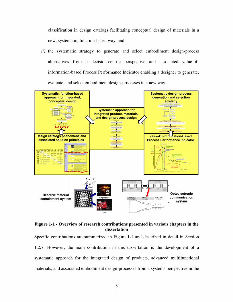
3
classification in design catalogs facilitating conceptual design of materials in a
new, systematic, function-based way, and
ii) the systematic strategy to generate and select embodiment design-process
alternatives from a decision-centric perspective and associated value-of-
information-based Process Performance Indicator enabling a designer to generate,
evaluate, and select embodiment design-processes in a new way.
temperature
impact
reactive
material
blast
Reactive material containment system
Optoelectronic communication
system
Systematic design-process generation and selection
strategy
Value-Of-Information-Based Process Performance Indicator
Design catalogs phenomena and associated solution principles
Systematic, function-based approach for integrated,
conceptual design
Systematic mapping of classified phenomena and solution pr inciples from multiple scales and discipl ines to multilevel function structures
Creating multilevel function structures based on functional analysis, abstraction and synthesis
Ex,in
M x,in
Ex,in
System boundary
System function x Exyz,out
System function z
System function y
Ey,in
Sz,i n
M x,in Sub-system function xx
Ex,out
Sub-system function xy
Sz,i n
Ey,in Material function yx
Eyz,o ut
Material function zx
Sub-system boundarySystem level
Sub-system level
Material level
Clarification of Task
Multilevel Function Structure Selection
Concept Selection
Concept
Principle
Phenomenon
Function
Pheno-menon
Scale Properties Applications
"Monolith ic" materials
- Metals Compared to all other classes of material, metals are stiff , strong and tough, but
they are heavy. They have relatively high mel ting points. Only one metal - gold - is
ch emicall y stable as a metal. Metals are ducti le, allowing the m to be shaped by
rolling, forging, drawingn and extrusion. They are easy to machine with preci si on,
and they can be joined in many different ways. Iron and nickel are transit ional metals i nvol ving both metal lic and coval ent bonds, and tend to be less ductile than
other metals. However, metals conduct electricity well, ref lect light and are
co mpletely opaque. Primary production of metals is energy intensive. Many
require at le ast twice as much energy per unit weight than commodity polymers.
But, metals can generally be recycled and the en ergy requi red to do so is much
less th an that requri ed for primary production. Some are toxic, others are so inert
that they can be implanted in the human body.
- Aluminum-, copper-,
mag nesi um-, nickel-, steel -,
titanium-, zi nc-al loys
- Carb on-, stainles-, …
steels - Amorphous metal s, …
Ela
stic
/in
elas
tic
de
form
ati
on
(te
ns
ion
, co
mp
res
sio
n, b
en
din
g, s
he
ar, t
ors
ion
, bu
ck
ling
, fr
act
ure
, c
utt
ing
, in
vers
ion
, e
xtru
sio
n,
Characteristics
Solution Principle
- Polymers
From a macroscale, monolithic materials are re ferred to as matter, i .e., the substance of which physical objects are composed.
Pol ymers feature an immense range of form, color, surface f inish, translucency,
transparency, toughness and flexibi lity. Ease of molding allows shapes that in
other materials could only be built up by expensive assembl y methods. Thei r
excell ent workabi lity allows the molding of complex forms, allowi ng cheap manufacture of integrated components that previ ousl y we re made by assembling
many parts. Many po lymers are cheap both to buy and shape. Most resist water,
acids and alkalis well , though organic solvents attack some. All are light and many
are f lexible. Their propert ies change rapi dly with te mperature. Even a t room
temperature ma ny creep and when cooled they may become brit tle. Polymers
generally are sensit ive to UV radi ation and to strongly oxidizing envi ronments.
- Thermospl astic po lymers:
ABS, Cellulose, Ionomers,
Nylo n/PA, PC, PEEK, PE,
PMMA, POM, PP, PS, PTFE, tpPVC, tpPU,
PET/PETE/PBT
- Thermosett ing pol ymers:
Epoxy, Phe nolic, Pol yester,
tsPU, tsPVC
- Elastome rs: Acrylic
machini ng.
Honeycomb-core
sandwiches
- In -pl ane honeycombs Core cell axes of in-plane honeycomb cores are oriented parall el to the face-sh eets. They provide potentials for decreased co nductivity and f luid flow with in
ce lls. Relati ve densiti es range from 0.001 to 0.3. Thei r densifi cation strain can be
approxi mated as:
Their relati ve stif fness can be ap proximated as:
Their relati ve strength can be approximated as:
- Prismatic-, square-, chiracal -, e tc. core in-plane
honeycombs
- Out-of-plane honeycombs Core cell axes of out-of-plane honeycomb cores are oriented perpendicular to
face-sheets. They provi de potential s fo r decreased conductivity. Rela tive d ensi ties
range from 0.001 to 0.3. Their densifi cation strain can be approximated as:
Their relati ve stif fness can be ap proximated as:
Their relati ve strength can be approximated as:
- Hexagon al-, sqaure-, etc.
core put-of-plane
honeycombs
Fiber-composites
- Conti nuous f iber
composi tes
Continuo us fi ber comp osi tes are composites with highe st st iffness and strength.
They are made of conti nuous f ibers usually embedded in a thermosett ing resi n.
The fib ers carry the mechanical loads while th e matrix material transmi ts l oads to
the fi bers and provides ductility and toughness as well a s protecting the f ibers
from damage ca used by handlin g or the environment. It is the matrix materi al that limits the service temperature and processing condit ions. On me soscales, the
properties can be strongly inf luenced by the choi ce of f iber and ma trix and th e
way in whi ch these are combined: f iber-resin ratio, fiber length , fiber orientation,
laminate thi ckness and th e presence of f iber/resin coupling agents to improve
bonding. The strength of a composi te is increased by raising the f iber-re sin rati o,
and orienting the fi bers parallel to the laoding directi on. Increased laminate
thickness leads to reduce d composi te strength and modulus as there is an
increased likeli hood of entrapped voids. Environmental condi tions affect the performance of composites: fatigue loadin g, moisture and heat all
reduce allowabl e strength. Po lyesters are the most most widel y use d matrices as
they offer reasonable p ropert ies at relatively low cost. The superior propert ies of
epoxies and the termperature performance of polyimides can justi fy their use in
ce rtain applicati ons, bu t they are expen sive.
- Glass f ibers [high strength
at low cost], polymer f ibers
(organic (e.g., Kevl ar) or
anorganic (e.g., Nylon,
Pol yester)) [reasonable properties at relatively l ow
cost], carbon fibers [very high
strength, st if fness and low
density]
- Strands, fila ments, fibers,
yarns (twisted strands),
rovi ngs (bundled strands)
- Nonwoven matt ings, weaves, braids, knits, other
- Discontinuou s fi ber
composi tes
Pol ymers reinforced with chopped po lymer, wood, glass or carbon fi bers are
referred to as discontinuous fi ber composites. The longer the fiber, the more eff icient is the reinforcement at carrying the applied loads, but shorter fibers are
easier to process and hence cheaper. Hence, fiber length and material are the
gove rni ng design varia bles. However, f ibrous core composites feature shape
fle xibi lity and relatively high bending stif fness a t low density.
- Glass f ibers, polymer fibers
(organic (e.g., Kevl ar) or anorganic (e.g., Nylon,
Pol yester)), carbon f ibers
Me
so
sca
le
Ela
stic
/in
elas
tic d
efo
rma
tion
(te
nsi
on
, co
mpr
essi
on,
bend
ing,
sh
ear,
tor
sio
n, b
uckl
ing
, fr
actu
re,
cutt
ing,
inv
ersi
on,
extr
usi
on,
draw
ing
,
flo
w)
Honeycomb-core sandwiches take their name from their visual resemblance to a bee 's honeycomb. W ith controllabl e core di mensions
and topol ogies on mesoscales, they freature relati vel y high stiffness and yi eld streng th at low density. Large compressive strai ns are
achievable at nomi nally constant stress (be fore the material compacts), yielding a potentially high energy absorptio n capacity. Honeycomb-
core sandwiches have acceptable structural performance at relatively low costs with useful combinati ons of thermophysical and
mechanical propert ies. Usua lly, they provide benefits with respect to multi ple use.
The combinati on of pol ymers or other matri x materials with fi bers has given a range of light material s with sti ffness and strength comparable to that of metal s. Commonly, resin materials are epoxies, polyesters and vinyl s. F ibers are much stronger and stif fer than
their equi vale nt in bul k fo rm because the drawing process by they are made ori ents the polymer chai ns along the fi ber axis or red uces the
density of defects.
−≈
s
Dρ
ρε 4.11
31rel
sE
Eρ≈
rel
ys
y ρσ
σ5.0≈
rel
sE
Eρ1≈
r el
ys
y ρσ
σ1≈
−≈
s
D ρ
ρε 4.11
Output
Input
Mechanical
Energy
(In)elastic de-
formation
Inertia
…
Electrostric-
tion
…
Magnetostric-
tion
…
Impact
…
Friction
…
Pressure
change
…
Dislocation
hardening
…
Electrostatic
EnergyElectric field…
Interference…
Hall-effect…
Electrostric-
tion
…
Photostric-
tion
…
Electrical
resistance
…
Galvanic
element
…
Magnetostatic
Energy
Magnetic field
…
Oscillating
circuit
…
Ferromag-
netism
…
Magneto-
striction
…
Farraday-
effect
…
Eddy current
…
Sound
Energy
Pressure wave
…
Electrostric-
tion
…
Magnetostric-
tion
…
Reflection
…
Noise dam-
ping
…
Elasticity
…
Light
Energy
Electromag-
netic radiation
…
Photostric-tion
…
Absorption
…
Refraction
…
Thermolumi-
nescence
…
Photoeffect
…
Thermal
Energy
Thermal
expansion
…
Thermoelectri
city
…
Curie-Weiss
law
…
Pyro-
electricity
…
Convection
…
Phase trans-
formation
…
Molecular
Energy
Exothermic
reaction
…
Molecular
dipoloe
…
Fluores-
cence
…
Combustion
Conductivity
…
Adhesion…
Light
Energy
Thermal
Energy
Molecular
Energy
Mechanical
Energy
Electrostatic
Energy
Magnetostatic
Energy
Sound
Energy
Design Variable
Exp
ecte
d O
ve
rall P
ayo
ff
Expected payoff usingdesign process alternative 1(global information)
Expected payoff using refined design process alternative 2(global information)
Payoff 2
Decision 1 Decision 2
Payoff 1
Process Performance Indicator 1
Expected payoff using most accurate physical or simulation models(local information)
Process Performance Indicator 2
Decisions based on predicted behavior using design process alternatives 1, 2, 3, etc.
Process Performance Indicator 3
Expected payoff using refined design process alternative 3(global information)
Payoff 3
Decision 3
Evaluation of design-process alternatives and additional modeling potential
through a value-of-information-based Process Performance Indicator
Systematic generation of design-process alternatives based on
principles from information economics
Design-Process Evaluation
Design-Process Selection
Concept Exploration and Selection
Template-based decision-centric embodiment design
2) Select and Evaluate Simple Ini tial
Desi gn Process Alternative.
4) Evaluate most t ruthful design process a lternative avail abl e.
S tep 7: Select satisfi cing embodiment
design process alternative.
1) Formulate Decision Using
Compromise DSP.
3) Determine Decision Point by Solving cDSP for Maximum Payoff.
High Process Per-
formance Indicator
Low Process Performance
Indicator
5) Eval uat e Process Performance Indicator
Simpl e Initial Design-Process Alternative .
6) Refine Design-Process and
Repeat Steps 3 Through 5.
…
Systematic approach for integrated product, materials,
and design-process design
Template-based decision-centric concept
exploration accounting for uncertainty and complexity of multilevel and multiscale design
Evaluation of design-process alternatives and value of additional multiscale modeling based on
Process Performance Indicator
Multilevel Function Structure Selection
Clarification of Task
Design-Process Design
Embodiment Design
Design-Process Selection
Concept Selection
Creating multilevel function structures based on
functional analysis, abstraction and synthesis
Systematic mapping of classified phenomena
and solution principles from multiple scales and disciplines to multilevel function structures
Systematic generation of multiscale design-process alternatives based on a value-of-
information-based strategy
Signal
(information
input)
Modulator Source
(carrier)
Detector Signal-
processor
Signal
(information
output)
Input- Output-
coupling
TRANSMITTER RECEIVER
a)
b)
NORMAL
WAVEGUIDE
OPTICAL
COUPLER
SLOW-LIGHT
WAVEGUIDE
Figure 1-1 - Overview of research contributions presented in various chapters in the
dissertation
Specific contributions are summarized in Figure 1-1 and described in detail in Section
1.2.7. However, the main contribution in this dissertation is the development of a
systematic approach for the integrated design of products, advanced multifunctional
materials, and associated embodiment design-processes from a systems perspective in the
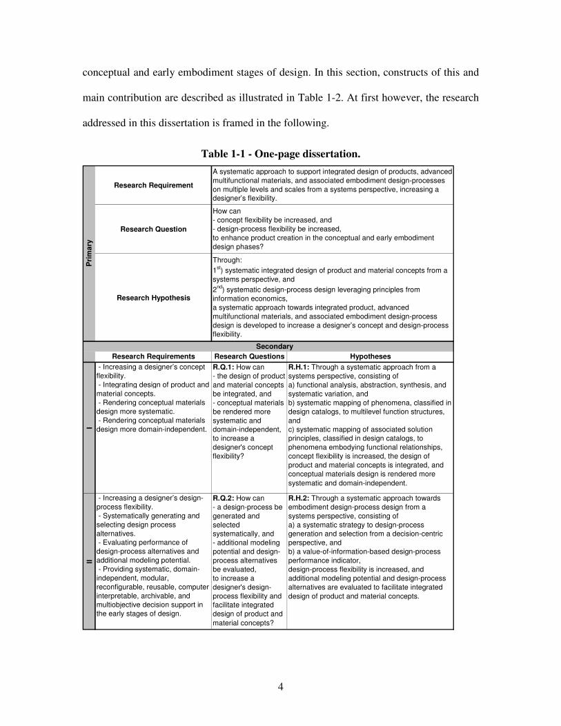
4
conceptual and early embodiment stages of design. In this section, constructs of this and
main contribution are described as illustrated in Table 1-2. At first however, the research
addressed in this dissertation is framed in the following.
Table 1-1 - One-page dissertation.
Research Requirement
Research Question
Research Hypothesis
Research Requirements Research Questions Hypotheses
I
- Increasing a designer’s concept
flexibility.
- Integrating design of product and
material concepts.
- Rendering conceptual materials
design more systematic.
- Rendering conceptual materials
design more domain-independent.
R.Q.1: How can
- the design of product
and material concepts
be integrated, and
- conceptual materials
be rendered more
systematic and
domain-independent,
to increase a
designer's concept
flexibility?
R.H.1: Through a systematic approach from a
systems perspective, consisting of
a) functional analysis, abstraction, synthesis, and
systematic variation, and
b) systematic mapping of phenomena, classified in
design catalogs, to multilevel function structures,
and
c) systematic mapping of associated solution
principles, classified in design catalogs, to
phenomena embodying functional relationships,
concept flexibility is increased, the design of
product and material concepts is integrated, and
conceptual materials design is rendered more
systematic and domain-independent.
II
- Increasing a designer’s design-
process flexibility.
- Systematically generating and
selecting design process
alternatives.
- Evaluating performance of
design-process alternatives and
additional modeling potential.
- Providing systematic, domain-
independent, modular,
reconfigurable, reusable, computer
interpretable, archivable, and
multiobjective decision support in
the early stages of design.
R.Q.2: How can
- a design-process be
generated and
selected
systematically, and
- additional modeling
potential and design-
process alternatives
be evaluated,
to increase a
designer's design-
process flexibility and
facilitate integrated
design of product and
material concepts?
R.H.2: Through a systematic approach towards
embodiment design-process design from a
systems perspective, consisting of
a) a systematic strategy to design-process
generation and selection from a decision-centric
perspective, and
b) a value-of-information-based design-process
performance indicator,
design-process flexibility is increased, and
additional modeling potential and design-process
alternatives are evaluated to facilitate integrated
design of product and material concepts.
Pri
ma
ry
Secondary
A systematic approach to support integrated design of products, advanced
multifunctional materials, and associated embodiment design-processes
on multiple levels and scales from a systems perspective, increasing a
designer’s flexibility.
How can
- concept flexibility be increased, and
- design-process flexibility be increased,
to enhance product creation in the conceptual and early embodiment
design phases?
Through:
1st) systematic integrated design of product and material concepts from a
systems perspective, and
2nd
) systematic design-process design leveraging principles from
information economics,
a systematic approach towards integrated product, advanced
multifunctional materials, and associated embodiment design-process
design is developed to increase a designer’s concept and design-process
flexibility.
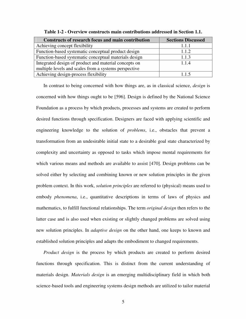
5
Table 1-2 - Overview constructs main contributions addressed in Section 1.1.
Constructs of research focus and main contribution Sections Discussed
Achieving concept flexibility 1.1.1
Function-based systematic conceptual product design 1.1.2
Function-based systematic conceptual materials design 1.1.3
Integrated design of product and material concepts on multiple levels and scales from a systems perspective
1.1.4
Achieving design-process flexibility 1.1.5
In contrast to being concerned with how things are, as in classical science, design is
concerned with how things ought to be [596]. Design is defined by the National Science
Foundation as a process by which products, processes and systems are created to perform
desired functions through specification. Designers are faced with applying scientific and
engineering knowledge to the solution of problems, i.e., obstacles that prevent a
transformation from an undesirable initial state to a desirable goal state characterized by
complexity and uncertainty as opposed to tasks which impose mental requirements for
which various means and methods are available to assist [470]. Design problems can be
solved either by selecting and combining known or new solution principles in the given
problem context. In this work, solution principles are referred to (physical) means used to
embody phenomena, i.e., quantitative descriptions in terms of laws of physics and
mathematics, to fulfill functional relationships. The term original design then refers to the
latter case and is also used when existing or slightly changed problems are solved using
new solution principles. In adaptive design on the other hand, one keeps to known and
established solution principles and adapts the embodiment to changed requirements.
Product design is the process by which products are created to perform desired
functions through specification. This is distinct from the current understanding of
materials design. Materials design is an emerging multidisciplinary field in which both
science-based tools and engineering systems design methods are utilized to tailor material
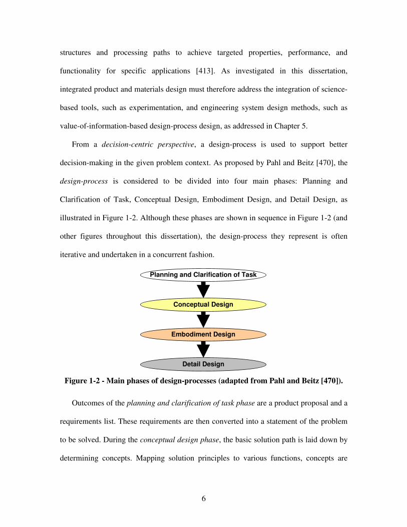
6
structures and processing paths to achieve targeted properties, performance, and
functionality for specific applications [413]. As investigated in this dissertation,
integrated product and materials design must therefore address the integration of science-
based tools, such as experimentation, and engineering system design methods, such as
value-of-information-based design-process design, as addressed in Chapter 5.
From a decision-centric perspective, a design-process is used to support better
decision-making in the given problem context. As proposed by Pahl and Beitz [470], the
design-process is considered to be divided into four main phases: Planning and
Clarification of Task, Conceptual Design, Embodiment Design, and Detail Design, as
illustrated in Figure 1-2. Although these phases are shown in sequence in Figure 1-2 (and
other figures throughout this dissertation), the design-process they represent is often
iterative and undertaken in a concurrent fashion.
Planning and Clarification of Task
Embodiment Design
Conceptual Design
Detail Design
Figure 1-2 - Main phases of design-processes (adapted from Pahl and Beitz [470]).
Outcomes of the planning and clarification of task phase are a product proposal and a
requirements list. These requirements are then converted into a statement of the problem
to be solved. During the conceptual design phase, the basic solution path is laid down by
determining concepts. Mapping solution principles to various functions, concepts are
7
generated and a principal solution, representing a more or less developed solution to the
overall problem statement, emerges. In terms of Pahl and Beitz, a concept or principal
solution may be as vague as a specification of working interrelationships needed for the
fulfillment of functional interrelationships [470]. The conceptual design phase is
followed by the embodiment design phase in which designers start from a principal
solution or multiple concepts and determine the structure of the system based on given
performance requirements. Details of the final design are then finally specified in the
detail design phase.
Since integrated product and materials design problems are characterized by
significant complexity and uncertainty, this dissertation is based on the notion of
satisficing solutions. Satisficing solutions are solutions that are “good enough” [596], as
opposed to optimizing solutions. The omnipresence of disturbing effects causing desired
or undesired side effects in real-world problems makes achieving optimizing solutions
impossible. A satisficer thus acknowledges that fact and accepts “good enough” solutions
because there is no choice [596].
In this dissertation, a systematic approach is developed to increase a designer’s
flexibility when solving design problems. As noted by Saleh and coauthors [560],
flexibility has become in recent years a key concept in many fields, particularly in most
design endeavors. According to Webster [715], being flexible in general refers to being
“willing or ready to yield to the influence of others, not invincibly rigid or obstinate,
tractable, manageable, …”. Definitions of flexibility and associated concept, design-
process, and product flexibility used throughout this dissertation are summarized in
Figure 1-3 and described in detail in Section 2.1.4.
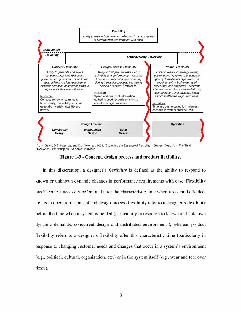
8
Flexibility
Ability to respond to known or unknown dynamic changes
in performance requirements with ease.
Concept Flexibility
Ability to generate and select concepts, map their respective
performance spaces as well as frame subproblems to allow response to
dynamic demands at different points in a product’s life cycle with ease.
Indicators:Concept performance ranges,
functionality, realizability, ease of generation, variety, quantity and novelty.
Design time line
Product Flexibility
Ability to realize open engineering systems and “respond to changes in
[the system’s] initial objectives and requirements – both in terms of
capabilities and attributes – occurring after the system has been fielded, i.e.,
is in operation, with ease in a timely
and cost-effective way” 1 with ease.
Indicators:Time and cost required to implement changes in system architectures.
Design Process Flexibility
Ability to “mitigate the risks – cost, schedule and performance – resulting
from requirement changes occurring during the design process, i.e., before
fielding a system” 1 with ease.
Indicators:
Speed and quality of information gathering used for decision making in
complex design processes.
Operation
Conceptual
Design
Embodiment
Design
Detail
Design
Management
FlexibilityManufacturing Flexibility
1 J.H. Saleh, D.E. Hastings, and D.J. Newman. 2001, “Extracting the Essence of Flexibility in System Design”. In The Third
NASA/DoD Workshop on Evolvable Hardware.
Figure 1-3 - Concept, design process and product flexibility.
In this dissertation, a designer’s flexibility is defined as the ability to respond to
known or unknown dynamic changes in performance requirements with ease. Flexibility
has become a necessity before and after the characteristic time when a system is fielded,
i.e., is in operation. Concept and design-process flexibility refer to a designer’s flexibility
before the time when a system is fielded (particularly in response to known and unknown
dynamic demands, concurrent design and distributed environments), whereas product
flexibility refers to a designer’s flexibility after this characteristic time (particularly in
response to changing customer needs and changes that occur in a system’s environment
(e.g., political, cultural, organization, etc.) or in the system itself (e.g., wear and tear over
time)).
9
In this dissertation, product flexibility maps to the ability to realize open engineering
systems, described by Simpson, Lautenschlager and Mistree as “systems of industrial
products, services and/or processes that are readily adaptable to changes in their
environment which enable producers to remain competitive in a global marketplace
through continuous improvement and indefinite growth of an existing technology base”
[597]. Additional information is provided in Section 2.1.5, along with various indicators
of flexibility. Having discussed the frame of reference, means to achieve concept
flexibility are addressed in the following section, as shown in Table 1-2.
1.1.1 On Achieving Concept Flexibility
Designing concepts, in other words determining key specifications, such as
functionality, physical structure, and performance ranges, has been shown to be critical to
the success of new products [36, 141, 505]. A concept is defined as “an idea that is
sufficiently developed to evaluate the physical principles that govern its behavior” [679].
The value of flexibility is obvious at the conceptual level. According to Krishnan and
Bhattacharya [344], the increasing emphasis on market leadership and shareholder value
creation have turned many firms’ attention to conceptual design as a source of growth,
renewal, and competitive advantage. During the conceptual phase, the most crucial
design stage in which decisions allocate the vast majority of a product’s resources,
system designers collaborating with expert designers need the flexibility to identify,
frame and select satisficing solutions that balance system-level objectives depending on
10
known or unknown dynamic demands with ease. In other words, concept flexibility is a
prerequisite to use new product development as a source of growth, renewal, and
competitive advantage.
Facing known or unknown dynamic demands, concept flexibility and consideration of
more than one technological option is crucial. Rapidly changing technological
capabilities and dynamic, seemingly unquenchable demands on limited resources in a
global marketplace require designers to consider prospective technologies that might not
yet be fully proven but offer the potential of superior performance, increased
functionality, economic feasibility, or adherence to new regulations. It has often been
said that working with a single concept is a recipe for disaster [516, 679]. Also, it has
been shown that being able to reach more points in the design space through concept
flexibility correlates strongly to higher quality design [174].
As has been shown in the car industry, applying set-based concurrent engineering, as
reviewed in detail in Section 2.2, and thereby emphasizing conceptual design efforts
makes finding the best or better solutions more likely while keeping faster development
cycles [616]. Also, studies of Fricke [218] and Ehrlenspiel et al. [181] have shown that
balanced expansion of solution spaces and frequent evaluation of solutions are success-
promoting factors. Hence, it is crucial to maintain concept flexibility, in other words
being able to foster a number of principal solutions in response to known or unknown
dynamic demands at the same time, as close to market introduction as possible with ease
when making crucial design decisions.
Conceptual and early embodiment design decisions are crucial and require close
interactions with customers. Hence, those can not be outsourced even though dynamic,
11
quasi unlimited demands on limited resources as well as growing consumer bases in a
global marketplace force enterprises to create the highest possible value while sourcing at
lowest cost. Thus, observing trends of outsourcing through which for example detail
design efforts are classified as “commodity work” [411] and “shipped” from highly
industrialized nations to emerging nations, this dissertation is focused on conceptual and
early embodiment design. Understanding what is required for firms to make the move
from the Information Age to the “Conceptual Age” (a phrase coined by Daniel H. Pink
[505]) is crucial to survive in the future global market.
In the Conceptual Age, concepts, i.e., key specifications for new products meeting
various customer requirements (which engineers have to analyze), are designed mostly in
higher-wage locations. At the same time, conceptual and early embodiment design is the
most crucial design stage in which decisions allocate the vast majority resources. Studies
have shown that 80-90 % of the costs of a product from manufacturing, maintenance and
disposal are determined in the conceptual design stage [56, 732]. Decisions made during
conceptual design have a major impact on downstream product development activities
and mistakes made during conceptual design are difficult to be compensated for in the
later stages. Therefore, conceptual design is considered to be among the most demanding
steps in design work and indeed the whole of engineering [281].
In this context, various approaches to increase a designer’s concept flexibility are
reviewed in Section 2.2, such as function-based systematic design [470], general solution
finding methods, set-based design [616], and design axioms [20, 522, 642]. Advantages
and limitations of these approaches are summarized in Table 2-5. However, as described
in detail in Section 2.2.1, it has been shown that a function-based systematic approach
12
supports a designer to solve design problems more efficiently and effectively than other
existing approaches [470], especially during the conceptual design phase. Hence, focus in
this dissertation is on function-based systematic conceptual design, as described in
greater detail in the following section.
1.1.2 Research Efforts in Function-Based Systematic Conceptual Product
Design
A well-established function-based systematic approach to conceptual product design
is the one proposed by Pahl and Beitz [470]. Steps of this approach are illustrated in
Figure 1-4. In this section, characteristics of this approach are reviewed first. Then, a
simple example of designing a device to uncork wine bottles is presented to illustrate
advantages and shortcomings of current function-based systematic approaches to
conceptual design as well as current conceptual product design practice. However, the
systematic design-proposed by Pahl and Beitz is reviewed in greater detail in Sections
2.2.1 and 3.2.
A systematic design-process, such as the one proposed by Pahl and Beitz [470], is
based on discursive and intuitive thinking. However, the key to systematic design is
discursive thinking – a conscious process that can be communicated and influenced, in
which scientific knowledge and relationships are consciously analyzed, varied, combined
in new ways, checked, rejected, and considered further [470]. Discursive thinking
involves successive steps of information transformation, which make problem solving
13
more systematic. Even though intuitive thinking – strongly associated with flashes of
inspiration – is significantly reduced, it is still required to some extent in systematic
design. Hence, the general solution finding methods reviewed in Section 2.2 can and
should be leveraged within systematic design. However, the main advantage of a
systematic approach is that designers do not have to rely on intuition and coming up with
a good idea at the right moment. Solution finding steps are archived and can always be
revisited and augmented to satisfy dynamic demands. More details on systematic design
are discussed in Section 4.2.
During the conceptual design phase within the Pahl and Beitz design-process,
illustrated in Figure 1-4, a designer determines a principal solution after completing the
clarification of task phase. This is achieved by abstracting the essential problems,
establishing function structures, searching for suitable working interrelationships (such as
working principles, surfaces, directions, etc.) and then combining those into a working
structure. Often, a working structure has to be transformed into a more concrete
representation, so that it is possible to evaluate essential aspects of a principal solution
and review design objectives and constraints. However, conceptual design results in the
specification of concepts. The design-process then continues on a more concrete level
referred to as embodiment and detail design.
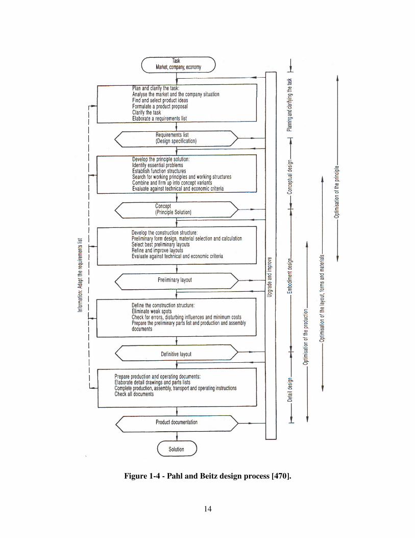
14
Figure 1-4 - Pahl and Beitz design process [470].
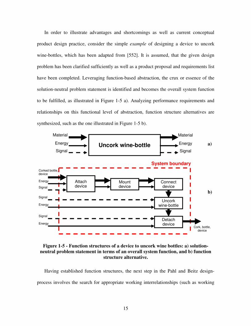
15
In order to illustrate advantages and shortcomings as well as current conceptual
product design practice, consider the simple example of designing a device to uncork
wine-bottles, which has been adapted from [552]. It is assumed, that the given design
problem has been clarified sufficiently as well as a product proposal and requirements list
have been completed. Leveraging function-based abstraction, the crux or essence of the
solution-neutral problem statement is identified and becomes the overall system function
to be fulfilled, as illustrated in Figure 1-5 a). Analyzing performance requirements and
relationships on this functional level of abstraction, function structure alternatives are
synthesized, such as the one illustrated in Figure 1-5 b).
Uncork wine-bottle
Material
Energy
Signal
Material
Energy
Signal
Attach device
Mount device
Connect device
Uncork wine-bottle
Detach device
System boundary
Corked bottle, device
Energy
Cork, bottle, device
Signal
Signal
Signal
Energy
Energy
Figure 1-5 - Function structures of a device to uncork wine bottles: a) solution-
neutral problem statement in terms of an overall system function, and b) function
structure alternative.
Having established function structures, the next step in the Pahl and Beitz design-
process involves the search for appropriate working interrelationships (such as working
a)
b)
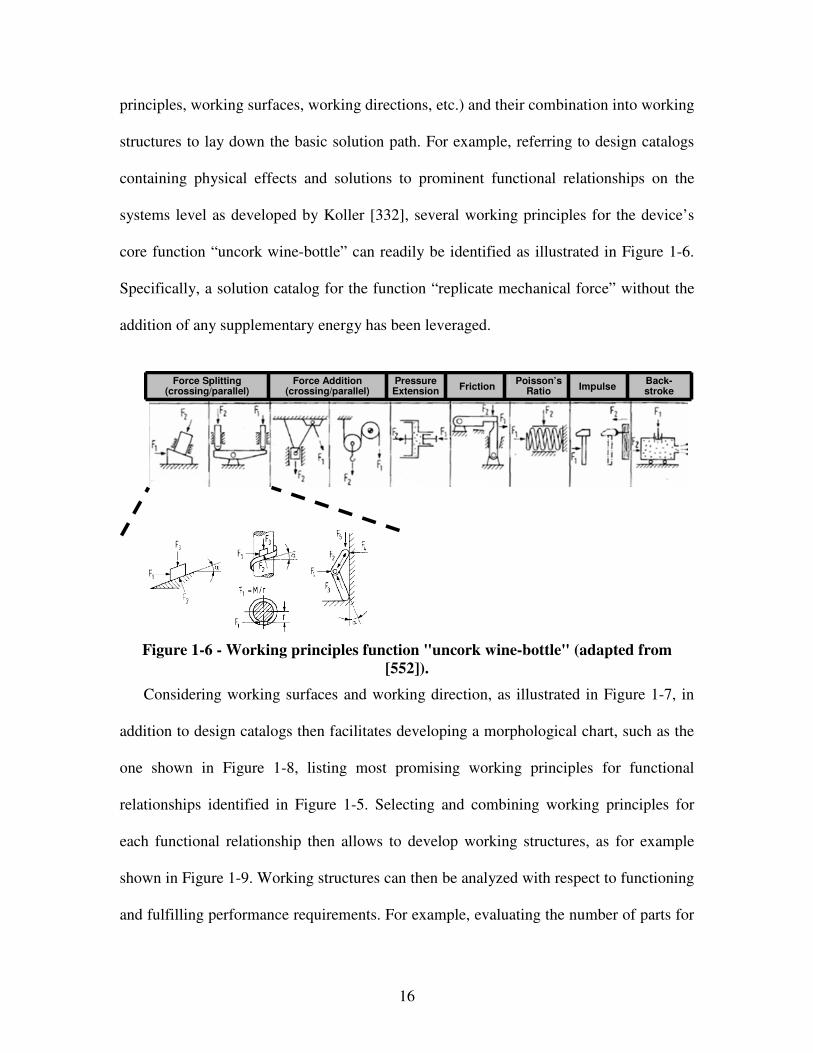
16
principles, working surfaces, working directions, etc.) and their combination into working
structures to lay down the basic solution path. For example, referring to design catalogs
containing physical effects and solutions to prominent functional relationships on the
systems level as developed by Koller [332], several working principles for the device’s
core function “uncork wine-bottle” can readily be identified as illustrated in Figure 1-6.
Specifically, a solution catalog for the function “replicate mechanical force” without the
addition of any supplementary energy has been leveraged.
Force Splitting
(crossing/parallel)Force Addition
(crossing/parallel)Pressure Extension Friction
Poisson’s Ratio Impulse
Back-stroke
Figure 1-6 - Working principles function "uncork wine-bottle" (adapted from
[552]).
Considering working surfaces and working direction, as illustrated in Figure 1-7, in
addition to design catalogs then facilitates developing a morphological chart, such as the
one shown in Figure 1-8, listing most promising working principles for functional
relationships identified in Figure 1-5. Selecting and combining working principles for
each functional relationship then allows to develop working structures, as for example
shown in Figure 1-9. Working structures can then be analyzed with respect to functioning
and fulfilling performance requirements. For example, evaluating the number of parts for
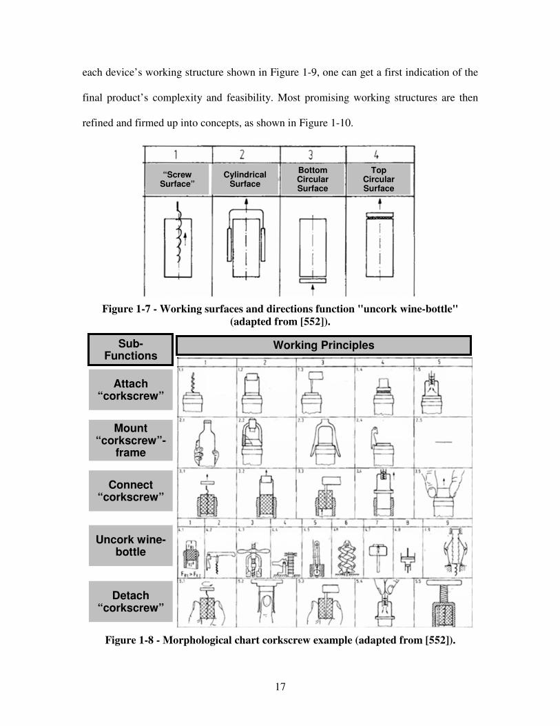
17
each device’s working structure shown in Figure 1-9, one can get a first indication of the
final product’s complexity and feasibility. Most promising working structures are then
refined and firmed up into concepts, as shown in Figure 1-10.
“Screw Surface”
Cylindrical Surface
Bottom Circular Surface
Top Circular Surface
Figure 1-7 - Working surfaces and directions function "uncork wine-bottle"
(adapted from [552]).
Attach “corkscrew”
Mount “corkscrew”-
frame
Connect “corkscrew”
Uncork wine-bottle
Detach “corkscrew”
Working PrinciplesSub-Functions
Figure 1-8 - Morphological chart corkscrew example (adapted from [552]).
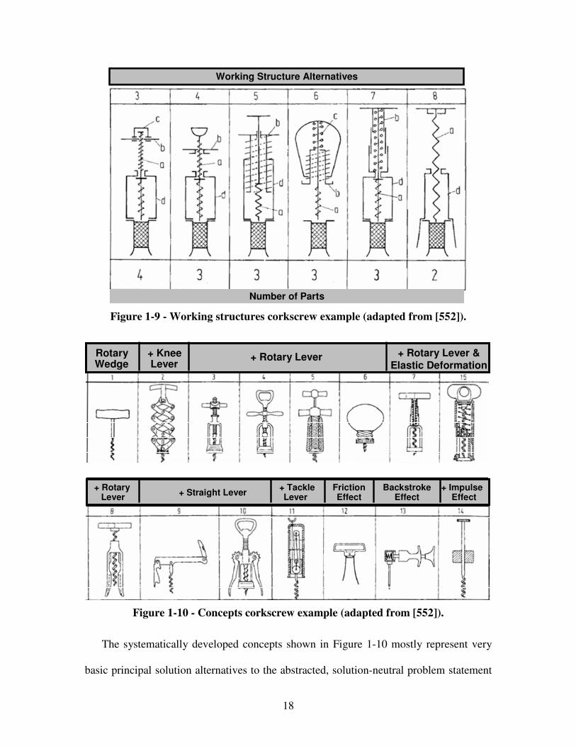
18
Working Structure Alternatives
Number of Parts
Figure 1-9 - Working structures corkscrew example (adapted from [552]).
Lever EffectNo
EffectFriction Effect
Lever Effect
Impulse Effect
Lever Effect
Lever EffectNo
EffectFriction Effect
Lever Effect
Impulse Effect
Lever Effect
Screw + Lever EffectNo
EffectLever Effect+ Knee Lever
+ Rotary LeverRotary Wedge
+ Rotary Lever &Elastic Deformation
Friction Effect
Backstroke Effect
+ Impulse Effect
+ Tackle Lever
+ Straight Lever+ Rotary
Lever
Figure 1-10 - Concepts corkscrew example (adapted from [552]).
The systematically developed concepts shown in Figure 1-10 mostly represent very
basic principal solution alternatives to the abstracted, solution-neutral problem statement
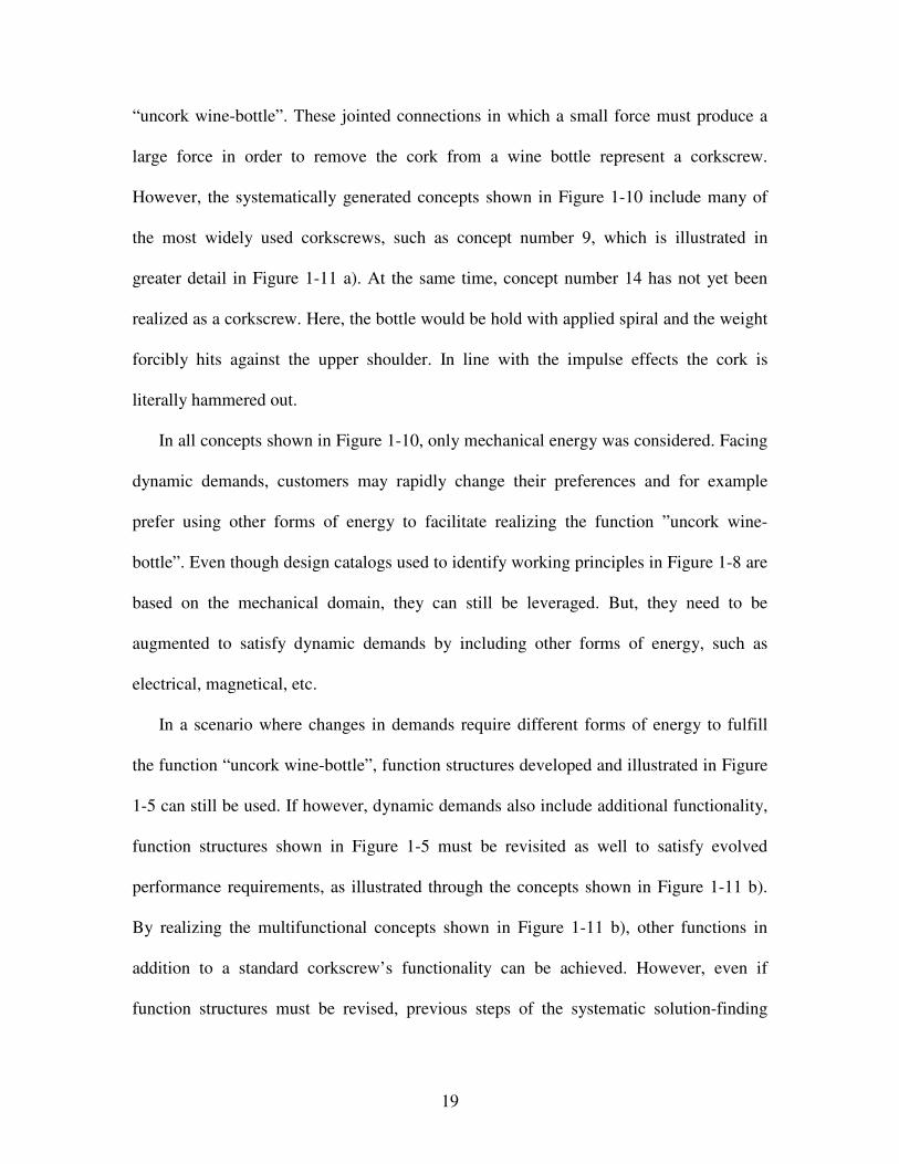
19
“uncork wine-bottle”. These jointed connections in which a small force must produce a
large force in order to remove the cork from a wine bottle represent a corkscrew.
However, the systematically generated concepts shown in Figure 1-10 include many of
the most widely used corkscrews, such as concept number 9, which is illustrated in
greater detail in Figure 1-11 a). At the same time, concept number 14 has not yet been
realized as a corkscrew. Here, the bottle would be hold with applied spiral and the weight
forcibly hits against the upper shoulder. In line with the impulse effects the cork is
literally hammered out.
In all concepts shown in Figure 1-10, only mechanical energy was considered. Facing
dynamic demands, customers may rapidly change their preferences and for example
prefer using other forms of energy to facilitate realizing the function ”uncork wine-
bottle”. Even though design catalogs used to identify working principles in Figure 1-8 are
based on the mechanical domain, they can still be leveraged. But, they need to be
augmented to satisfy dynamic demands by including other forms of energy, such as
electrical, magnetical, etc.
In a scenario where changes in demands require different forms of energy to fulfill
the function “uncork wine-bottle”, function structures developed and illustrated in Figure
1-5 can still be used. If however, dynamic demands also include additional functionality,
function structures shown in Figure 1-5 must be revisited as well to satisfy evolved
performance requirements, as illustrated through the concepts shown in Figure 1-11 b).
By realizing the multifunctional concepts shown in Figure 1-11 b), other functions in
addition to a standard corkscrew’s functionality can be achieved. However, even if
function structures must be revised, previous steps of the systematic solution-finding
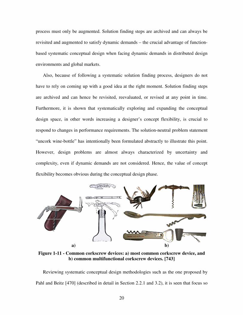
20
process must only be augmented. Solution finding steps are archived and can always be
revisited and augmented to satisfy dynamic demands – the crucial advantage of function-
based systematic conceptual design when facing dynamic demands in distributed design
environments and global markets.
Also, because of following a systematic solution finding process, designers do not
have to rely on coming up with a good idea at the right moment. Solution finding steps
are archived and can hence be revisited, reevaluated, or revised at any point in time.
Furthermore, it is shown that systematically exploring and expanding the conceptual
design space, in other words increasing a designer’s concept flexibility, is crucial to
respond to changes in performance requirements. The solution-neutral problem statement
“uncork wine-bottle” has intentionally been formulated abstractly to illustrate this point.
However, design problems are almost always characterized by uncertainty and
complexity, even if dynamic demands are not considered. Hence, the value of concept
flexibility becomes obvious during the conceptual design phase.
a) b)
Figure 1-11 - Common corkscrew devices: a) most common corkscrew device, and
b) common multifunctional corkscrew devices. [743]
Reviewing systematic conceptual design methodologies such as the one proposed by
Pahl and Beitz [470] (described in detail in Section 2.2.1 and 3.2), it is seen that focus so
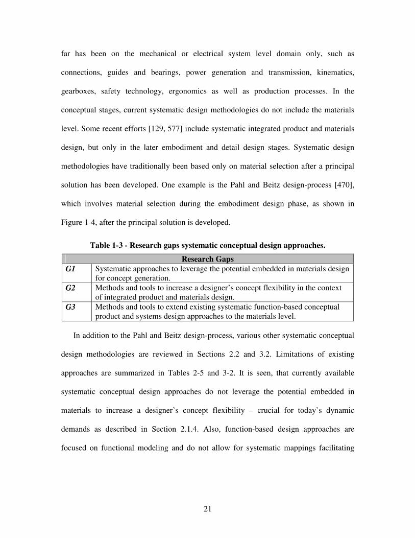
21
far has been on the mechanical or electrical system level domain only, such as
connections, guides and bearings, power generation and transmission, kinematics,
gearboxes, safety technology, ergonomics as well as production processes. In the
conceptual stages, current systematic design methodologies do not include the materials
level. Some recent efforts [129, 577] include systematic integrated product and materials
design, but only in the later embodiment and detail design stages. Systematic design
methodologies have traditionally been based only on material selection after a principal
solution has been developed. One example is the Pahl and Beitz design-process [470],
which involves material selection during the embodiment design phase, as shown in
Figure 1-4, after the principal solution is developed.
Table 1-3 - Research gaps systematic conceptual design approaches.
Research Gaps
G1 Systematic approaches to leverage the potential embedded in materials design for concept generation.
G2 Methods and tools to increase a designer’s concept flexibility in the context of integrated product and materials design.
G3 Methods and tools to extend existing systematic function-based conceptual product and systems design approaches to the materials level.
In addition to the Pahl and Beitz design-process, various other systematic conceptual
design methodologies are reviewed in Sections 2.2 and 3.2. Limitations of existing
approaches are summarized in Tables 2-5 and 3-2. It is seen, that currently available
systematic conceptual design approaches do not leverage the potential embedded in
materials to increase a designer’s concept flexibility – crucial for today’s dynamic
demands as described in Section 2.1.4. Also, function-based design approaches are
focused on functional modeling and do not allow for systematic mappings facilitating
22
concept generation. Hence, research gaps derived from the critical literature review in
Sections 2.2 and 3.2 are summarized in Table 1-3.
It is acknowledged that most applications require materials to satisfy multiple
functions that cannot be defined in isolation from system level conditions and
performance requirements. Hence, focus in this dissertation is on enhancing existing
function-based systematic design approaches by incorporating the potential embedded in
materials design to increase a designer’s concept flexibility, in other words on developing
a function-based systematic approach to the integrated design of product and materials
concepts. A prerequisite for integrated design of product and materials concepts however
is a function-based systematic conceptual materials design approach, discussed in the
following section.
1.1.3 Research Efforts in Function-Based Systematic Conceptual
Materials Design
Materials are fundamental to design, and throughout the history have dictated its
opportunities and its limits. The evolution of materials began with humankind’s use of
naturally occurring materials. Materials have had a profound impact on the evolution of
word civilizations. Historians have classified periods in this evolution by the materials
that were the state-of-the-art during these periods. Thus, the vocabulary now contains
phrases like the Stone Age, the Bronze Age, and the Iron Age. Each of these eras is
characterized by the material that was most advanced of its time. By the twentieth
23
century an embryonic technology involving synthetic materials had emerged - plastics.
This was a profound departure from the traditional approach of exploiting natural
materials with their known defects and limitations.
Synthetic plastic materials replaced traditional materials in a diverse range of
industries. The reason was their extensive range of physical properties that could comply
precisely with the performance requirements. However, in the following, a variety of
functional materials, such as gallium arsenide or magnetostrictive materials, have been
developed to exploit functional properties instead of solely structural properties. The
availability of functional materials has then made the development of advanced
composite materials possible. The characteristic of advanced composite materials is that a
combination of two or more constituent materials creates a material with engineering
properties superior to those of the constituents – albeit at the expense of more challenging
fabrication technologies.
It is not the age of just one material; it is the age of an immense range of materials
and the combinations these allow. There has never been an era in which the evolution of
materials was faster and the sweep of their properties more varied. The availability of
materials expands so rapidly that designers may not keep track. However, ignorance is
not an option. Innovative designs are often enabled through innovative materials. Also,
there is no reason to expect that the pace of material development will slow. Innovations
in the materials domain will continue to drive disruptive technologies, mostly in response
to engineering problems, i.e., in a problem-directed (need driven) fashion rather than
through “technology push” (technology driven).
24
Designing materials to solve engineering problems may lead to achieve system
performance goals for the first time or realize “smart” materials and “artificially
intelligent systems”. In the encyclopedia of chemical technology [347], smart materials
are defined as objects that sense environmental events, process that sensory information
and then act on the environment. Smart materials may inherently act as sensors or
actuators. In their role as sensors, a smart material responds to changes in its environment
by generating a perceivable response. For example, a thermochromic material could be
used directly as a device for sensing a change in the temperature of an environment via its
color response capabilities. Smart materials such as piezoelectric crystals could also be
used as actuators by passing an electric current through the material to create a force. The
goal of materials design thus becomes to tailor materials depending on what primary
system functions they are intended to serve. Materials design from a systems perspective
may thus lead to “artificially intelligent systems”, i.e.,
• environments featuring automation and information technology, such as central
sensor controlled and programmable talking washing machines, or
• embedded, information-rich, multimodal environments that are anticipatory and
context-aware of occupants, such as recognition systems (body tracking, voice,
gesture, aural, touch, smell, taste), and computationally-assisted task
augmentation via embedded interfaces.
Future approaches might even feature increasing cognition and context-aware
response levels suggestive of biological systems, but may also see an evolution of the
personal environment (i.e., a trend towards personalization) and a devolution of
traditional physical boundaries, as described by [380]. More details and examples are
25
discussed in Chapters 4 and 6, where a function-based methodology and design catalogs
respectively are developed. However, enhancing existing function-based systematic
design approaches by incorporating the potential embedded in materials design to
increase a designer’s concept flexibility, in other words developing a function-based
systematic approach to the integrated design of product and materials concepts, is crucial
when facing dynamic demands.
Current materials design approaches do not address the conceptual design phase – the
most crucial design stage in which decisions allocate the vast majority of a product’s
resources – in a systematic fashion. Besides the development of advanced methodologies
for material selection [27, 28], a paradigm shift towards materials design with the
objective of tailoring the chemical composition, constituent phases, microstructure and
processing paths to obtain materials with desired properties for particular applications has
begun [129, 350, 413, 459, 475, 581]. So far, however, materials design has mostly been
exercised in the embodiment phase focusing on simulation-based multiscale modeling
techniques developed recently [53, 129, 475].
As argued by Eberhart and Clougherty [175], no matter how fast the computer, if it
must search for an optimum property using accurate analysis models of an infinite
number of materials, it will still require infinite time to perform the search. Hence, the
viewpoint of materials design as an automated search exercise is very limited. Also,
scientific, mostly complex multiscale models might not be necessary in many cases
because the goal of materials design is not to accurately predict material properties but to
satisfy performance requirements. Furthermore, bottom-up analysis is not design. The
26
key to materials design is an interplay of multiscale modeling with human decision-
making.
A detailed review of materials design is presented in Section 2.1.3. Limitations of
existing approaches are summarized in Table 2-4. However, in order to not limit
materials design to detail or embodiment design, a function-based systematic approach to
conceptual materials design is proposed in this dissertation. Research gaps are
summarized in Table 1-4.
Table 1-4 - Research gaps conceptual materials design.
Research Gaps
G4 Systematic approaches to conceptual materials design.
G5 Methods and tools for rendering conceptual materials design more domain-independent in the context of integrated product and materials design.
The focus in this work is to identify and classify structure-property relations on
multiple length scales to facilitate the design of material concepts to be further
investigated through systems-based embodiment materials design, in line with Smith’s
observation that structure is best considered as a hierarchy, with each of its levels
characterized by a different length scale [610]. With respect to systematic conceptual
materials design, the idea to establish function-based systematic conceptual materials
design focusing on phenomena and associated solution principles – structure-property
relations – but not an infinite number of cases or material artifacts.
In this context, the essence of the function-based approach to conceptual materials
design presented in this dissertation is to enable designers identifying underlying
phenomena and associated solution principles rather than a prescriptive set of directions
simply to instruct in the implementation of new materials and technologies. Also,
materials design is an emerging multidisciplinary field with two main trusts in
27
mechanical engineering (specifically materials science and chemistry) and electrical
engineering (specifically electronics). Hence, by focusing on phenomena and associated
solution principles embodying identified functional relationships but not the material
artifact, a designer is able to overcome disciplinary boundaries and step out of the
technological cycle of obsolescence and evolution. But, as a result, this approach requires
a much more active engagement by the designer than do the typical selection approaches.
If knowledge of a material/system is tied only into an account of its
properties/specifications and a description of its current application, then that knowledge
may become obsolete along with the material/system quickly. By operating at the level of
phenomena and associated solution principles, a particular material/system at any given
time is only illustrative of the possibilities, not their determinant. As materials/systems
cycle through evolution and obsolescence, the questions that are raised by their uses
should remain. Hence, it is crucial to leverage phenomena and associated solution
principles to design and develop products that have a dynamic behavior and provide that
knowledge in classified form for easy retrieval, as investigated in Research Question 1.
However, a function-based approach to conceptual materials is a prerequisite for
integrated design of product and material concepts as discussed in the following section.
1.1.4 Motivating Integrated design of product and material concepts on
multiple levels and scales from a systems perspective
Integrated materials and product design efforts involving phenomena and associated
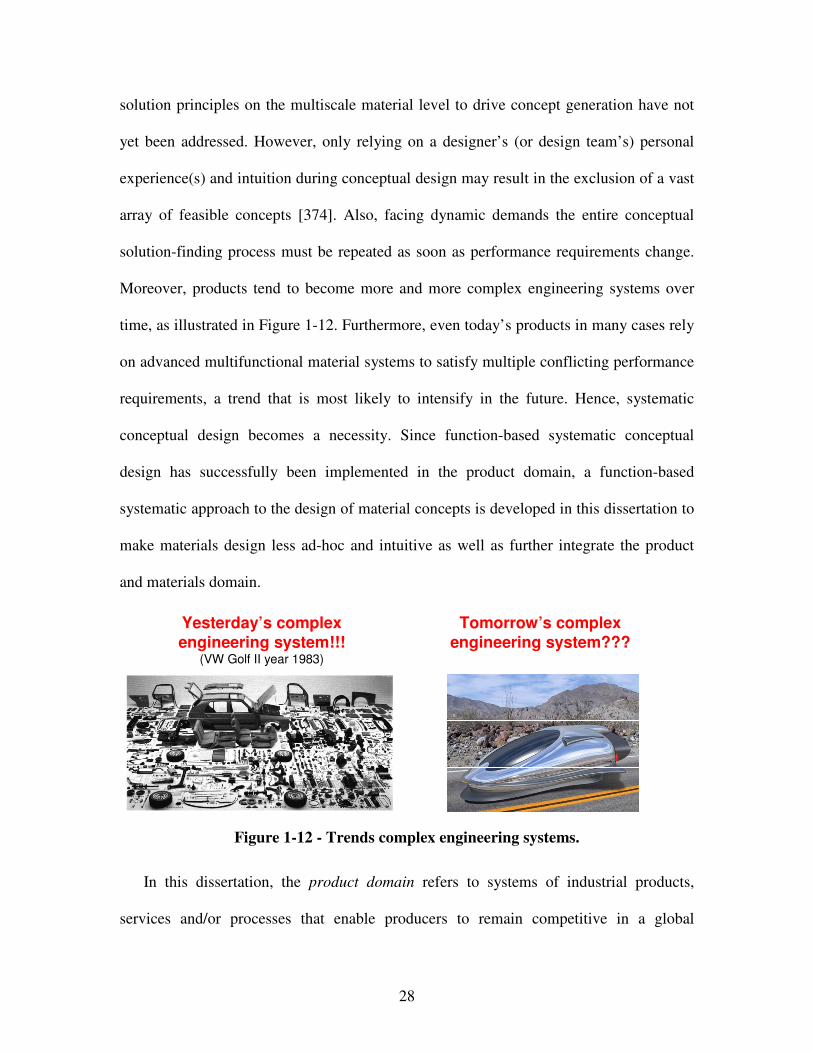
28
solution principles on the multiscale material level to drive concept generation have not
yet been addressed. However, only relying on a designer’s (or design team’s) personal
experience(s) and intuition during conceptual design may result in the exclusion of a vast
array of feasible concepts [374]. Also, facing dynamic demands the entire conceptual
solution-finding process must be repeated as soon as performance requirements change.
Moreover, products tend to become more and more complex engineering systems over
time, as illustrated in Figure 1-12. Furthermore, even today’s products in many cases rely
on advanced multifunctional material systems to satisfy multiple conflicting performance
requirements, a trend that is most likely to intensify in the future. Hence, systematic
conceptual design becomes a necessity. Since function-based systematic conceptual
design has successfully been implemented in the product domain, a function-based
systematic approach to the design of material concepts is developed in this dissertation to
make materials design less ad-hoc and intuitive as well as further integrate the product
and materials domain.
Yesterday’s complex engineering system!!!
(VW Golf II year 1983)
Tomorrow’s complex engineering system???
Figure 1-12 - Trends complex engineering systems.
In this dissertation, the product domain refers to systems of industrial products,
services and/or processes that enable producers to remain competitive in a global
29
marketplace, as for example addressed in the open engineering system paradigm
introduced by Simpson, Lautenschlager and Mistree [597]. The term materials domain as
used in this dissertation refers to materials that are actually made up of several basic
building blocks, constituted in a way to achieve particular properties and thereby satisfy
performance requirements.
A thermoelectric material for example consists of multiple layers, where each layer
can be regarded as a different material. However, most advanced multifunctional
materials actually “work” at meso or lower scales and are thus not visible to the human
eye. Furthermore, heterogeneous microstructures always affect macroscale performance.
Hence, the effect produced by materials “mechanisms” on various length scales are
visible at the macro scale. Research in materials science has enabled designers to
consider such lower scale materials mechanisms on for example properties of composites
or metallic systems. However, especially during conceptual design, materials property-
structure relations are not considered. This challenge is addressed in this dissertation.
Therefore, problem-oriented thinking from a systems perspective drives use of the term
“material” in this dissertation. Hence, systems perspective refers to a holistic
understanding of the scientific phenomena and solution principles at multiple levels and
scales in this dissertation.
In this context, a system refers to a group of functionally interrelated, interacting, or
interdependent constituents forming a complex whole [715] within a system boundary,
composed of a number of subsystems where each subsystem is embodied by a particular
set of components, or sub-subsystems [328], as shown in Figure 1-13. A subsystem is
thus a part of a system which is considered a system itself (comprised of multiple
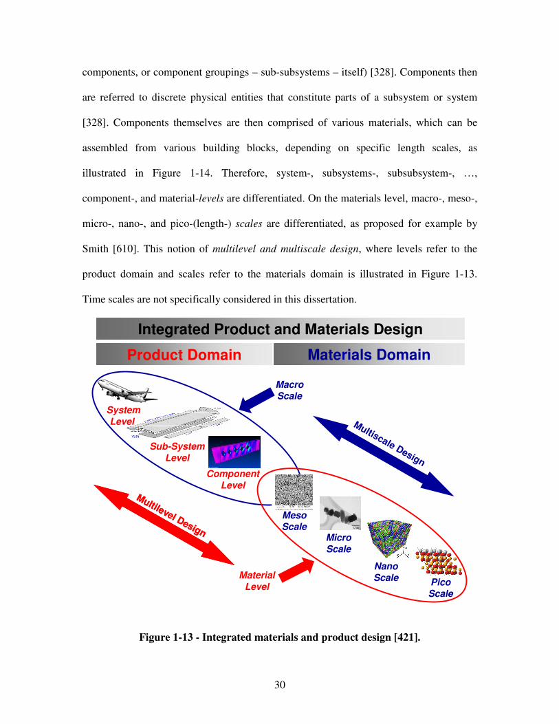
30
components, or component groupings – sub-subsystems – itself) [328]. Components then
are referred to discrete physical entities that constitute parts of a subsystem or system
[328]. Components themselves are then comprised of various materials, which can be
assembled from various building blocks, depending on specific length scales, as
illustrated in Figure 1-14. Therefore, system-, subsystems-, subsubsystem-, …,
component-, and material-levels are differentiated. On the materials level, macro-, meso-,
micro-, nano-, and pico-(length-) scales are differentiated, as proposed for example by
Smith [610]. This notion of multilevel and multiscale design, where levels refer to the
product domain and scales refer to the materials domain is illustrated in Figure 1-13.
Time scales are not specifically considered in this dissertation.
Product Domain Materials Domain
System
Level
Sub-System
Level
Component
Level
Integrated Product and Materials Design
Material
Level
MacroScale
NanoScale
Micro
Scale
MesoScale
PicoScale
Multiscale Design
Multilevel Design
Multilevel Design
Figure 1-13 - Integrated materials and product design [421].
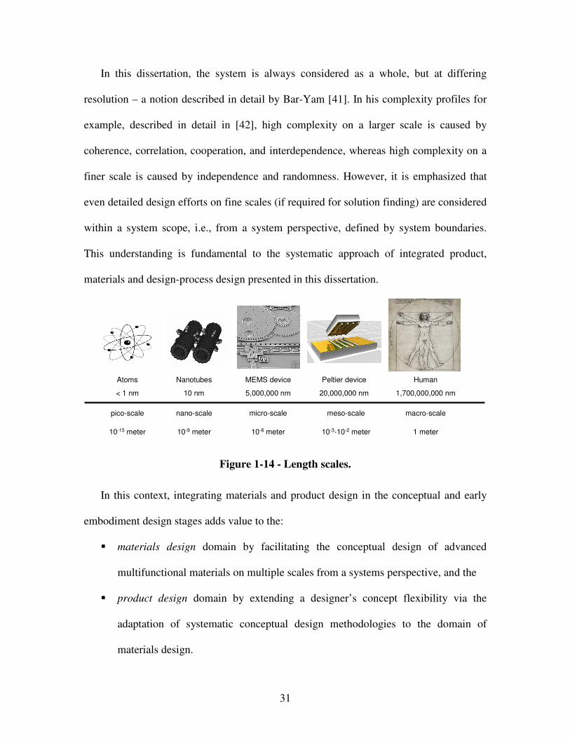
31
In this dissertation, the system is always considered as a whole, but at differing
resolution – a notion described in detail by Bar-Yam [41]. In his complexity profiles for
example, described in detail in [42], high complexity on a larger scale is caused by
coherence, correlation, cooperation, and interdependence, whereas high complexity on a
finer scale is caused by independence and randomness. However, it is emphasized that
even detailed design efforts on fine scales (if required for solution finding) are considered
within a system scope, i.e., from a system perspective, defined by system boundaries.
This understanding is fundamental to the systematic approach of integrated product,
materials and design-process design presented in this dissertation.
pico-scale nano-scale micro-scale meso-scale macro-scale
10-13 meter 10-9 meter 10-6 meter 10-3-10-2 meter 1 meter
Atoms
< 1 nm
Nanotubes
10 nm
MEMS device
5,000,000 nm
Peltier device
20,000,000 nm
Human
1,700,000,000 nm
Figure 1-14 - Length scales.
In this context, integrating materials and product design in the conceptual and early
embodiment design stages adds value to the:
� materials design domain by facilitating the conceptual design of advanced
multifunctional materials on multiple scales from a systems perspective, and the
� product design domain by extending a designer’s concept flexibility via the
adaptation of systematic conceptual design methodologies to the domain of
materials design.
32
For example, consider a designer faced with the task of controlling light and heat
supply into a room. Following conventional product design processes during the
conceptual design phase, the designer may design a double-glazing window, a rolling
shutter system composed out of many subsystems (such as the shutter itself, the electric
motor, gearbox, etc.), and some control unit to adapt light and heat supply into a room.
However, by considering materials design even at the conceptual level, the designer may
design a light and heat supply system consisting of electrochromic glass only.
Electrochromic glass can simultaneously be a glazing material, a window, a lighting
control system, a thermometer or an automated shading system – hence, it is an advanced
multifunctional material. More details on electrochromic glasses are reviewed in Chapter
4. Related technologies include liquid crystals and suspended particles devices that
change color or transparencies when electrically activated.
As illustrated in this example, designing materials and products in an integrated
fashion from the conceptual stage on, designers are enabled to realize new functionality
and improved system performance through comprehensive identification and integration
of phenomena and associated governing solution principles on multiple levels and scales
from multiple disciplines, such as chemistry, materials science, materials physics,
mechanics of materials, electronics, information technology, and mechanical engineering.
The opportunities for novel solutions for materials, products, as well as their design,
modeling and realization processes are manifold. Exercising integrated materials and
product design significantly increases the accessible design space compared to exercising
product design followed by materials selection or materials design during the
embodiment and detail design phases. Compared to conventional product design,
33
integrating product and materials design therefore increases a designer’s flexibility in
achieving system performance objectives or realizing certain functionality for the first
time and hence enhancing a designer’s concept flexibility. However, it also requires
methods and tools to increase a designer’s design-process flexibility as discussed in the
following section.
1.1.5 On Achieving Design-Process Flexibility
Leveraging phenomena and associated solution principles occurring at multiple levels
and scales through integrated product and materials design is advantageous to achieve
enhanced concept flexibility and increased overall system performance, but,
disadvantageous in the sense that a designer has to face:
• strong couplings and interactions not only between subsystems and multiple
disciplines, but also physical phenomena at various scales that must be explicitly
modeled and accounted for in decision making,
• fundamentally different (multiscale and multiphysics) types of more or less
developed analysis models (possibly describing the same physical phenomena) on
and within various scales that may fundamentally change upon refinement,
• integration of simulation methods with measurement systems, model validation
and verification,
• uncertainty generation and propagation not only between subsystems but also
between and within various scales that must be addressed, and
34
• significantly greater complexity of design-processes than in conventional systems,
displayed in an unmanageably large number of interactions and couplings denoted
by the number of independent design variables, inhibiting extensive and agile
design space exploration through holistic design processes consisting of rigidly
integrated analysis models.
These characteristics in the design of complex engineered systems and advanced
multifunctional materials require a designer to manage uncertainty and complexity in
design-processes, in other words in a network of decisions and models on multiple levels
and scales, in order to increase design-process flexibility.
Approaches to manage uncertainty and complexity as well as design-process
flexibility include multidisciplinary optimization [92, 143, 246, 328, 346, 617, 620, 663,
740], interval-based design [92, 102, 475, 577], game-based design [118, 142, 205, 265,
368, 397, 399, 474, 697], metamodel-based design [15, 38, 39, 57, 58, 70, 116, 145, 197,
269, 330, 359, 372, 407, 436, 442, 464, 468, 521, 548, 603, 669, 701-704, 714, 736, 737,
741, 742], robust design [111, 129, 656-658], or value-of-information-based design
derived from information economics [31, 33, 64, 65, 104, 183, 184, 247, 283, 351, 352,
478, 502, 549, 601, 619], as reviewed in detail in Sections 2.3 and 5.2. Except for value-
of-information-based design, these approaches are severely limited with respect to the
problem of size, system-level bottlenecks, computational intractability, or highly
nonlinear and discontinuous design spaces, as described in detail in Section 2.3 and
summarized in Table 2-6.
Value-of-information-based design is based on metrics derived from Information
Economics [31, 33, 475] – defined as “…the study of choice in information collection
35
and management when resources to expend on information collection are scarce” [33].
Value-of-information-based metrics refer to measuring the impact of simplification on
the final design outcome. But, current metrics are limited to scenarios where knowledge
of design-process prediction accuracy or its error bounds is known throughout the whole
design space. Additionally, metrics and value-of-information-based strategies, such as the
ones proposed by Panchal [478], focus on simplifying/refining design-processes by either
decoupling interactions or replacing analysis models. However, both scenarios, and
especially model replacement with fundamentally different types of analysis models
connected in series and parallel, are frequently encountered in the integrated design of
product and materials. Limitations of current approaches are described in detail in
Section 5.2 and summarized in Table 5-2. Research gaps are summarized in Table 1-5.
Table 1-5 - Research gaps design-process design.
Research Gaps
G6 Methods and tools to increase a designer’s design-process flexibility in the context of integrated product and materials design.
G7 Systematic strategies for managing complexity through design-process design allowing for both decoupling interactions and replacing analysis models
G8 Methods and tools to evaluate design-processes when knowledge of prediction accuracy or its error bounds is not known throughout the whole design space
In this work, focus is on a systematic strategy to design-process generation and
selection based on a value-of-information-based Process Performance Indicator. As
reviewed in Section 5.2, value-of-information-based indicators have been proven useful
for managing complexity, especially in the context of evaluating coupling strength in
multiscale design-processes. However, the assumption of existing value-of-information-
based metrics is that prediction accuracy, associated probability bounds, or bounds on the
36
prediction accuracy of a design-process are truthful and available globally, i.e.,
throughout the whole design. But, complexity often makes development of physics-based
models tedious. Especially in the context of integrated product and materials design,
experimental testing is often less tedious and hence should be leveraged for decision
making.
Also, in most engineering scenarios, system behavior is predicted through
experimentation, prototype or specimen testing, or evaluation of extremely
computationally expensive design-process alternatives. This is specially true in the
context of integrated product and materials design. Due to uncertainty about many
physical phenomena spanning various length and time scales, simulation is extremely
computationally expensive and experimentation is a generally accepted modeling
technique. Also, various methods exists to predict the behavior of system components
based on standardized or custom-made specimen test data. This however, is only feasible
at isolated points in the design space. Hence, the assumption of existing value-of-
information-based metrics that prediction accuracy or associated probability bounds are
truthful and available globally, i.e., throughout the whole design, is not valid in most
integrated product and materials design scenarios.
Furthermore, in various circumstances, a designer has access to different kinds of
analysis models constituting design-process alternatives that embody different
assumptions, but, the error bounds on those models are unavailable throughout the whole
design-space. In the context of integrated product and materials design, it is not
practically feasible to either know a model’s error or associated probability bounds
throughout the whole design space or generate those through an “educated guess” in
37
terms of p-boxes. Also, in this context it is not considered feasible to know the behavior
of a most truthful model throughout the whole design space because different analysis
models predicting the same response might be based on fundamentally different physical
assumptions. Hence, for these scenarios, the current value-of-information-based metrics
need to be extended.
Moreover, the assumption of aforementioned approaches is that designers have the
knowledge of a complete network of decisions and analysis models, which is first
simplified and then sequentially refined again. Based on this knowledge, the least
complex network configuration is executed first. Then, the network configuration is
sequentially refined and evaluated until a satisficing design-process alternative is
achieved. However, this is a significant limitation in the integrated design of products and
materials on multiple levels and scales, because the number of interactions is
significantly higher than in conventional product design, and the number of network
configurations prohibits the sequential exploration of design-process alternatives. Due to
the number of interactions and design-process alternatives in the integrated product and
materials design on multiple levels and scales, knowledge of the complete network of
decisions and analysis models upfront as well as sequential exploration of design-process
alternatives is prohibited.
In order to address the aforementioned limitations and challenges specifically in the
context of integrated product and materials design, the development of a strategy to
systematic design-process generation and selection based on principles from information
economics including a value-of-information-based Process Performance Indicator is
further investigated in Research Question 2. However, example problems to test the

38
systematic function-based approach to conceptual materials design as well as the
systematic strategy to design-process generation and selection including a value-of-
information-based Process Performance Indicator are addressed in the following section.
1.1.6 Motivating Example Problems
The systematic approach to integrated product, materials, and design-process design
developed in this dissertation is validated using the following two example problems: i) a
reactive material containment system, and ii) an optoelectronic communication system. In
the context of these example problems, the goal is to show how a designer’s concept and
design-process flexibility is increased through the integrated design of advanced
multifunctional material and product concepts as well as associated embodiment design-
processes. Both design problems are from different disciplines, i.e., mechanics and
electronics respectively. Both disciplines are known to direct research efforts as well as
oversee applications in materials design – one focused on energy stimuli, kinematic
(active) behavior and material structure, the other focused on microelectronics. Thus,
using design problems from both these disciplines is beneficial with respect to validating
the proposed systematic approach to integrated product, materials, and design-process
design.
The reactive material containment system example problem is used to test the
systematic approach for integrated product, materials, and design-process design
developed in this work as a whole. The optoelectronic communication system example
39
problem is used to test the strategy to design-process generation and selection along with
the value-of-information-based Process Performance Indicator in particular. Both design
problems are introduced in the following
Reactive Material Containment System Example Problem
Currently, reactive materials are transported to their destinations in enclosures
consisting of monolithic panels. Also, the more or less advanced materials of the reactive
material containment system are mostly selected from a finite set of available materials.
However, in order to minimize adverse economic and environmental effects while
ensuring safe handling at satisfactory reactivity, customers pose conflicting requirements
such as:
• minimization of reaction probability during transport,
• maximization of reaction probability during usage,
• maximization of collision resistance, and
• minimization of system weight.
Therefore, the overall system has to be designed in order to ensure satisfactory
performance, i.e., reactivity, of the reactive material to be transported as well as its safe
handling, i.e., protection against collisions which may cause impacts, high temperatures
and blasts as shown in Figure 1-15, while minimizing overall system weight. Thus, to
solve this design problem, functionalities (and related properties) from the chemical and
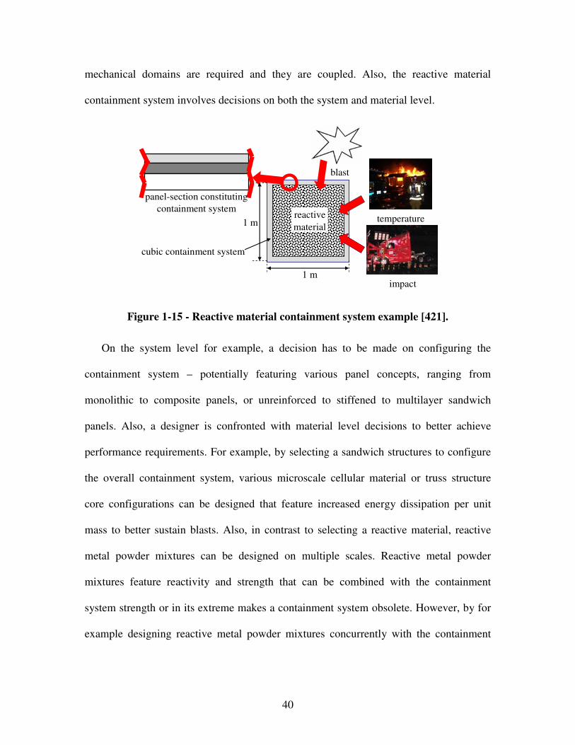
40
mechanical domains are required and they are coupled. Also, the reactive material
containment system involves decisions on both the system and material level.
temperature
impact
reactive
material
blast
cubic containment system
panel-section constituting
containment system
1 m
1 m
Figure 1-15 - Reactive material containment system example [421].
On the system level for example, a decision has to be made on configuring the
containment system – potentially featuring various panel concepts, ranging from
monolithic to composite panels, or unreinforced to stiffened to multilayer sandwich
panels. Also, a designer is confronted with material level decisions to better achieve
performance requirements. For example, by selecting a sandwich structures to configure
the overall containment system, various microscale cellular material or truss structure
core configurations can be designed that feature increased energy dissipation per unit
mass to better sustain blasts. Also, in contrast to selecting a reactive material, reactive
metal powder mixtures can be designed on multiple scales. Reactive metal powder
mixtures feature reactivity and strength that can be combined with the containment
system strength or in its extreme makes a containment system obsolete. However, by for
example designing reactive metal powder mixtures concurrently with the containment
41
system, reactivity and level of blast protection can be customized and hence increase a
designer’s concept flexibility.
In the context of this example problem, the goal is to show how to increase system
performance as well as a designer’s concept and design-process flexibility through the
integrated design of advanced multifunctional material and product concepts as well as
associated embodiment design process. For example, currently designers are limited in
the sense that they can only select a certain quantity of reactive material while designing
a containment system concept. Having conceptually designed the containment system,
most likely the strongest and toughest as well as lightest materials available are selected
to embody the containment system concept and fulfill the given performance
requirements best.
By designing products and advanced multifunctional materials in an integrated
fashion from the conceptual stage on, designers may gain greater flexibility, as in its
extreme envisioned in Gershenfeld’s personal nano-fabricator assembling any object
atom by atom [178]. For example, designers do not need to limit themselves to select an
available reactive material but may consider the design of Multifunctional Energetic
Structural Materials (MESM), i.e., reactive metal powder mixtures, serving the dual
purpose of providing both energy storage and strength to a reactive system. Furthermore,
designers can consider the design of multifunctional panels that compromise the
containment system, providing the functions of both strength and increased energy
absorption per unit mass. But, designing and exploring product and material concepts in
an integrated fashion, a satisficing embodiment design-process alternative should be
identified for rapid concept exploration during the embodiment design phase.
42
The reactive material containment system example is a reasonably complex
multilevel and multiscale design problem. The design problem allows significant increase
in system performance by exercising systematic conceptual design not only on various
system levels down to the component level, but, also on the multiscale materials level
Moreover, the problem is suitable because many aspects of integrated product and
materials design can be demonstrated. Furthermore, the embodiment design-process can
be represented in terms of decisions that can be mathematically formulated and supported
using analysis models of different complexity. Hence, the reactive material containment
system example consists of decisions related to three aspects: product, materials, and
design-process design. All three decisions depend on each other and ultimately affect the
final system performance. Therefore, the reactive material containment system is well
suited to be used for validating the systematic approach to integrated product, materials,
and design-process design developed in this dissertation.
Optoelectronic Communication System Example Problem
Consider the design of a next-generation optoelectronic communication system, as
illustrated in Figure 1-16, for specialized applications, such as long-distance data
transmission, operating at a specific wavelength and low receiver intensity. Since the
design of a next-generation optoelectronic communication system for specialized
applications operating at specific wavelengths and low receiver intensity is required,
enhanced means for signal propagation and dispersion control must be provided. Typical
43
optical propagation and dispersion control components not only cause additional cost or
complexity especially in an extreme environment installation or military application, but
also significantly decrease signal-to-noise ratios in the signal by amplifying noise.
Specifically, noise is amplified because signal processing is typically not performed
before amplification. Hence, based on the phenomena design catalog given in Table 4-3,
the photonic crystal phenomenon is leveraged to design waveguides, based on advanced
multifunctional materials, coupled to a detector in a next-generation optoelectronic
communication system.
Photonic crystal waveguides offer unprecedented control over the propagation and
dispersion of light. However, there are significant difficulties encountered when coupling
light into these waveguides from traditional optical waveguides. Particularly, when
making a transition from one type of waveguide to another, there will inevitably be
reflections at the transition. These reflections are undesirable, as they reduce the amount
of light that enters the second waveguide. An imperfect but illuminating analogy would
be a broad river that is abruptly forced through a narrow channel. One would expect there
to be 'backup' of water behind the transition area. The proposed solution is a tapered
waveguide, which will “ease” the transition between the two waveguides, and thereby
minimize reflections. To reuse the river analogy, it would be similar to gradually tapering
in the river banks in order to force most of the water to continue flowing in the narrow
channel. Also, when “squeezing” light from traditional into photonic crystal waveguides
operating in a “slow-light” region, it is important to slow the group velocity of light down.
Therefore, one is most interested in the design of:
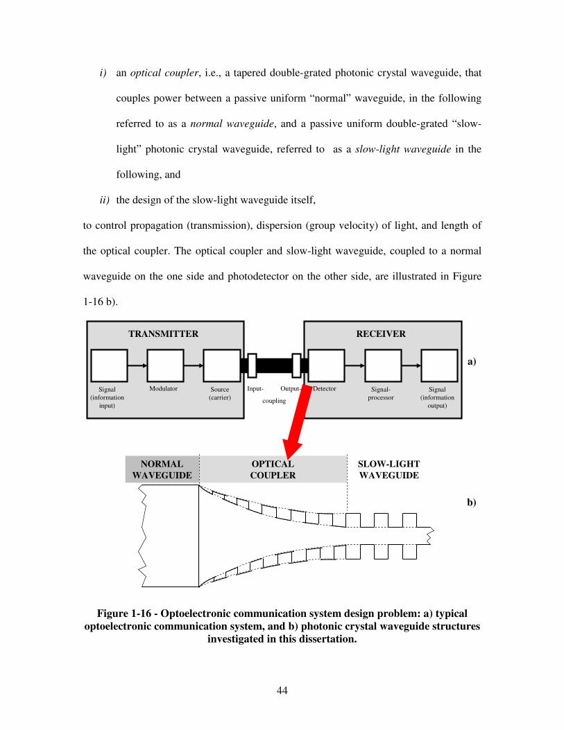
44
i) an optical coupler, i.e., a tapered double-grated photonic crystal waveguide, that
couples power between a passive uniform “normal” waveguide, in the following
referred to as a normal waveguide, and a passive uniform double-grated “slow-
light” photonic crystal waveguide, referred to as a slow-light waveguide in the
following, and
ii) the design of the slow-light waveguide itself,
to control propagation (transmission), dispersion (group velocity) of light, and length of
the optical coupler. The optical coupler and slow-light waveguide, coupled to a normal
waveguide on the one side and photodetector on the other side, are illustrated in Figure
1-16 b).
Signal
(information
input)
Modulator Source
(carrier)
Detector Signal-
processor
Signal
(information
output)
Input- Output-
coupling
TRANSMITTER RECEIVER
a)
b)
NORMAL
WAVEGUIDE
OPTICAL
COUPLER
SLOW-LIGHT
WAVEGUIDE
Figure 1-16 - Optoelectronic communication system design problem: a) typical
optoelectronic communication system, and b) photonic crystal waveguide structures
investigated in this dissertation.
45
In order to achieve the design goals, the photonic crystal waveguides are designed
involving parameters of the grating at microscales and taper at macroscale to tailor
“effective” optical properties of the multifunctional photonic crystal waveguide
components in the optoelectronic system context. In order to do so, more or less complex
design-process alternatives can be generated and selected, such as effective index models,
bandgap models, Fourier modal models, or very detailed finite difference models. In this
context, the goal is to show how to increase a designer’s design-process flexibility by
using the value-of-information-based design-process generation and selection strategy
developed in this dissertation.
Since designing double-grated photonic crystal waveguides in the context of a next-
generation optoelectronic communication system involves deciding on both material and
product design variables, the design problem involves the integrated design of products
and materials. The decisions about the product and constituting materials are coupled
with each other because both decisions impact achievement of performance requirements
and behavior of the product-material system. Having generated a principal solution to the
complete product-material system, the focus is on using this example problem to test the
systematic strategy and value-of-information-based Process Performance Indicator
developed in this dissertation and thereby increasing a designer’s design-process
flexibility by designing the product-material system and associated embodiment design-
processes in an integrated fashion.
The optoelectronic communication system example is a reasonably complex
multilevel and multiscale design problem. The design problem allows significant increase
in system performance by exercising systematic conceptual design not only on various
46
system levels down to the component level, but, also on the multiscale materials level
Furthermore, the embodiment design-process can be represented in terms of decisions
that can be mathematically formulated and supported using analysis models of different
complexity. Hence, designing double-grated photonic crystal waveguides for the
optoelectronic communication system consists of decisions related to three aspects:
product, materials, and design-process design. All three decisions depend on each other
and ultimately affect the final system performance. Therefore, the optoelectronic
communication system example problem is well suited to be used for validating the
value-of-information-based design-process generation and selection strategy developed in
this dissertation.
Some applications described here may be considered unnecessary, too expensive in
some of the more traditional engineering areas given the current state of technology, or
too utopian. However, the possibilities are fascinating and the examples investigated
provide useful suggestions to trigger novel ideas for hitherto conventional systems
fostering integrated product and materials design. Also, increased use will make designs
more common and hence less expensive, even though the cost/benefit ratio of specific life
cycle phases might not always seem in line with current market economics.
In the context of the example problems introduced above, it can be seen that today’s
sequential process of first designing the product and then selecting materials from a
limited set of available materials restricts the accessible design space and therefore a
designer’s flexibility. By designing the product, advanced multifunctional materials and
associated embodiment design processes in an integrated fashion from the beginning,
47
concept and design-process flexibility are increased to overcome design restrictions
imposed by materials selection for revolutionary product creation, as for example in its
extreme visionized in Gershenfeld’s personal nano-fabricator assembling any object atom
by atom [178].
Having motivated the need for integrated product, materials and design-process
design in the early phases of design in Section 1.1, research questions and requirements
are presented in the following section.
1.2 Research Questions and Hypotheses
Facing conflicting requirements in a world of dynamic, seemingly unquenchable
demands on limited resources, the integrated design of product and advanced
multifunctional materials concepts as well as associated design-processes is crucial in a
global marketplace. Observing trends of outsourcing, through which for example detail
design efforts are classified as “commodity work” [411] and “shipped” from highly
industrialized nations to emerging nations, generating and exploring concepts as well as
framing and detailing the associated embodiment design-processes are the essential tasks
faced by designers. Hence, increasing a designer’s flexibility in generating, framing and
exploring system concepts (concept flexibility) and associated embodiment design-
processes (design-process flexibility) through a systematic approach towards function-
48
based integrated product, materials, and design-process design becomes crucial. Having
reviewed the constructs of the research focus and main contribution, gaps identified in the
previous sections are summarized in the following section and a research overview is
given.
1.2.1 Research Gaps and Overview
The focus in this dissertation is on the integrated design of products, advanced
multifunctional material, and associated embodiment design-processes to increase a
designer’s flexibility, specifically concept and design-process flexibility. Interestingly,
decision making in early design phases has not attracted adequate research attention.
How to define the product, material or design-process amidst customer, technology, and
environmental uncertainty remains largely an open question. However, it is this
uncertainty which makes design flexibility indisipensable. In the preceding sections,
limitations of current approaches to achieve concept and design-process flexibility have
been reviewed. Research gaps have been summarized in Table 1-3, Table 1-4, and Table
1-5 and are repeated in the following:
• G1: Systematic approaches to leverage the potential embedded in materials design
for concept generation.
• G2: Methods and tools to increase a designer’s concept flexibility in the context of
integrated product and materials design.
49
• G3: Methods and tools to extend existing systematic function-based conceptual
product and systems design approaches to the materials level.
• G4: Systematic approaches to conceptual materials design.
• G5: Methods and tools for rendering conceptual materials design more domain-
independent in the context of integrated product and materials design.
• G6: Methods and tools to increase a designer’s design-process flexibility in the
context of integrated product and materials design.
• G7: Systematic strategies for managing complexity through design-process design
allowing for both decoupling interactions and replacing analysis models.
• G8: Methods and tools to evaluate design-processes when knowledge of prediction
accuracy or its error bounds is not known throughout the whole design space.
Based on these gaps, research questions as well as associated hypotheses and
requirements are derived in the following section
1.2.2 Introducing Research Questions and Hypotheses
Based on the preceding gap analyses, the primary research question to be answered
in this dissertation is:
50
How can
• concept flexibility be increased, and
• design-process flexibility be increased,
to enhance product creation in the conceptual and early embodiment design
phases?
In response, the primary research hypothesis is:
Through:
1st) systematic integrated design of product and material concepts from
a systems perspective, and
2nd
) systematic design-process design leveraging principles from
information economics,
a systematic approach towards integrated product, advanced multifunctional
materials, and associated embodiment design-process design is developed to
increase a designer’s concept and design-process flexibility.
Based on the primary research hypothesis and preceding gap analyses, the primary
research requirement in this dissertation on the integrated design of products, materials,
and design-processes is:
51
A systematic approach to support integrated design of products, advanced
multifunctional materials, and associated embodiment design-processes on
multiple levels and scales from a systems perspective, increasing a designer’s
flexibility.
Specifically, the following key requirements are to be addressed:
• increasing a designer’s concept flexibility,
• integrating design of product and material concepts,
• rendering conceptual materials design more systematic,
• rendering conceptual materials design more domain-independent,
• increasing a designer’s design-process flexibility,
• systematically generating and selecting design process alternatives,
• evaluating performance of design-process alternatives and additional modeling
potential, and
• providing systematic, domain-independent, modular, reconfigurable, reusable,
computer interpretable, archivable, and multiobjective decision support in the
early stages of design.
Based on these key requirement, the primary research question is divided into two
secondary research questions, Research Question 1 and Research Question 2:
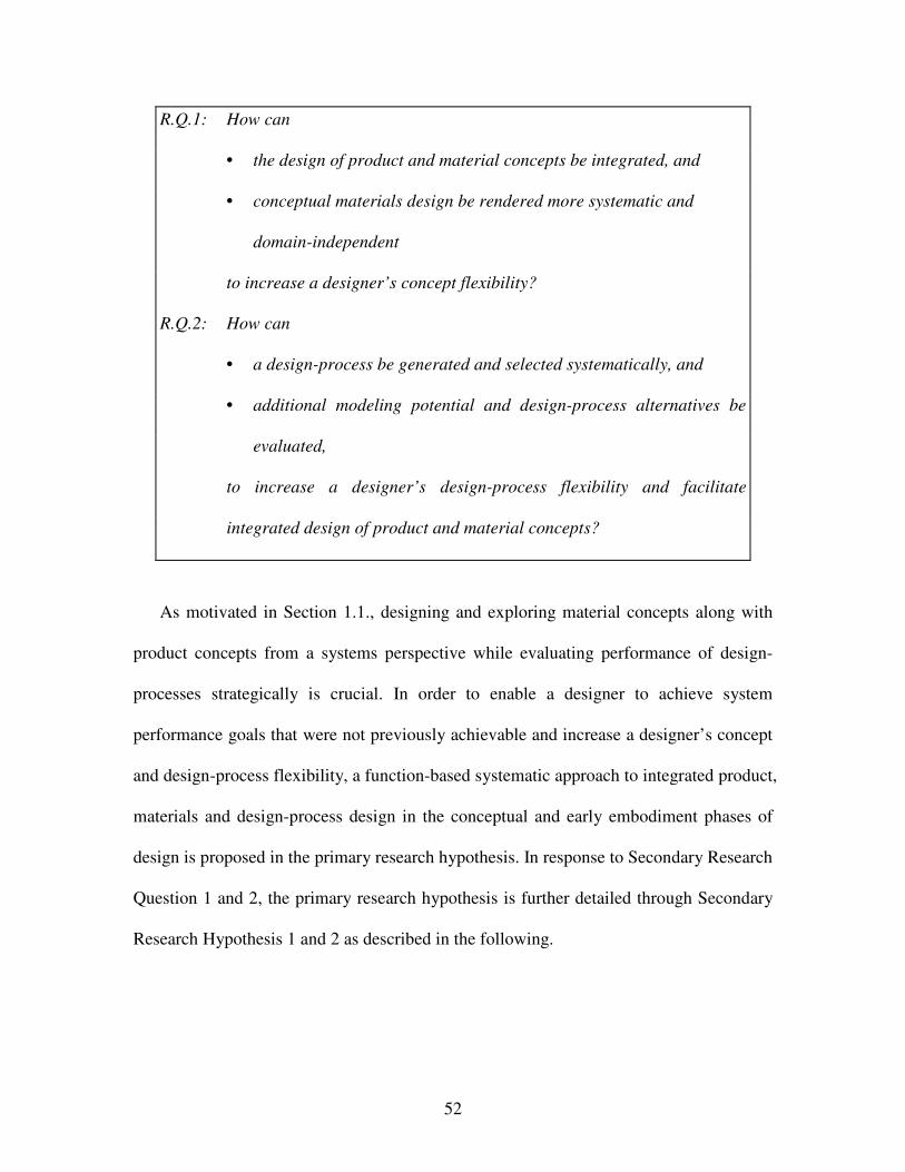
52
R.Q.1: How can
• the design of product and material concepts be integrated, and
• conceptual materials design be rendered more systematic and
domain-independent
to increase a designer’s concept flexibility?
R.Q.2: How can
• a design-process be generated and selected systematically, and
• additional modeling potential and design-process alternatives be
evaluated,
to increase a designer’s design-process flexibility and facilitate
integrated design of product and material concepts?
As motivated in Section 1.1., designing and exploring material concepts along with
product concepts from a systems perspective while evaluating performance of design-
processes strategically is crucial. In order to enable a designer to achieve system
performance goals that were not previously achievable and increase a designer’s concept
and design-process flexibility, a function-based systematic approach to integrated product,
materials and design-process design in the conceptual and early embodiment phases of
design is proposed in the primary research hypothesis. In response to Secondary Research
Question 1 and 2, the primary research hypothesis is further detailed through Secondary
Research Hypothesis 1 and 2 as described in the following.
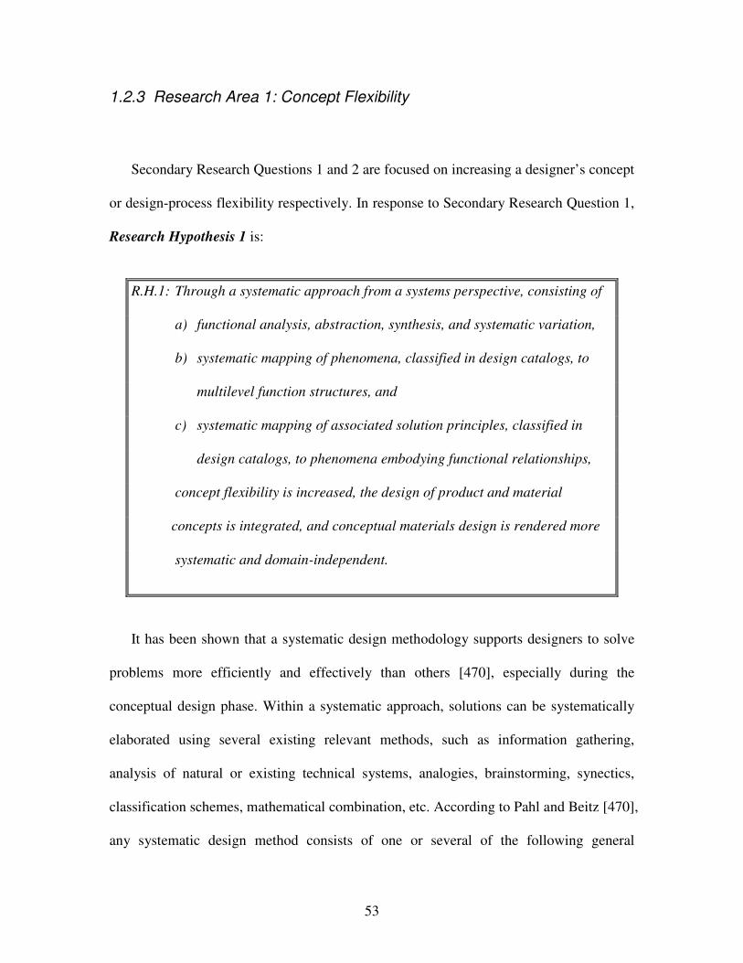
53
1.2.3 Research Area 1: Concept Flexibility
Secondary Research Questions 1 and 2 are focused on increasing a designer’s concept
or design-process flexibility respectively. In response to Secondary Research Question 1,
Research Hypothesis 1 is:
R.H.1: Through a systematic approach from a systems perspective, consisting of
a) functional analysis, abstraction, synthesis, and systematic variation,
b) systematic mapping of phenomena, classified in design catalogs, to
multilevel function structures, and
c) systematic mapping of associated solution principles, classified in
design catalogs, to phenomena embodying functional relationships,
concept flexibility is increased, the design of product and material
concepts is integrated, and conceptual materials design is rendered more
systematic and domain-independent.
It has been shown that a systematic design methodology supports designers to solve
problems more efficiently and effectively than others [470], especially during the
conceptual design phase. Within a systematic approach, solutions can be systematically
elaborated using several existing relevant methods, such as information gathering,
analysis of natural or existing technical systems, analogies, brainstorming, synectics,
classification schemes, mathematical combination, etc. According to Pahl and Beitz [470],
any systematic design method consists of one or several of the following general
54
methods: analysis, abstraction, synthesis, method of persistent questions, method of
negation, method of forward steps, methods of backward steps, method of factorization,
method of systematic variation, division of labor and collaboration. From these general
methods, function-based decomposition, analysis, abstraction, synthesis and systematic
variation are leveraged as core transformations for the systematic approach presented in
this dissertation.
Function-based design, i.e., function-based analysis, abstraction, synthesis, and
systematic variation, has proven to be most effective and efficient in the mechanical and
electrical engineering domain, as described by Pahl and Beitz [470], Koller [332],
Clausen and Rodenacker [138], Roth [552], and Orloff [462]. Focus however has so far
been on mechanical engineering domain-specific applications, such as connections,
guides and bearings, power generation and transmission, kinematics, gearboxes, safety
technology, ergonomics as well as production processes. Multidisciplinary integrated
materials and product design efforts involving phenomena and associated solution
principles on the material level to drive concept generation have not been addressed. In
this domain, concept flexibility is currently achieved with ad hoc methods that rely on the
experience and intuition of expert designers. Hence, enhancing existing function-based
systematic design approaches by incorporating the potential embedded in materials
design and leveraging materials structure-property relations to increase a designer’s
concept flexibility while rendering materials design more systematic and domain-
independent is addressed in Chapters 3 and 4 as proposed in Research Hypothesis 1.
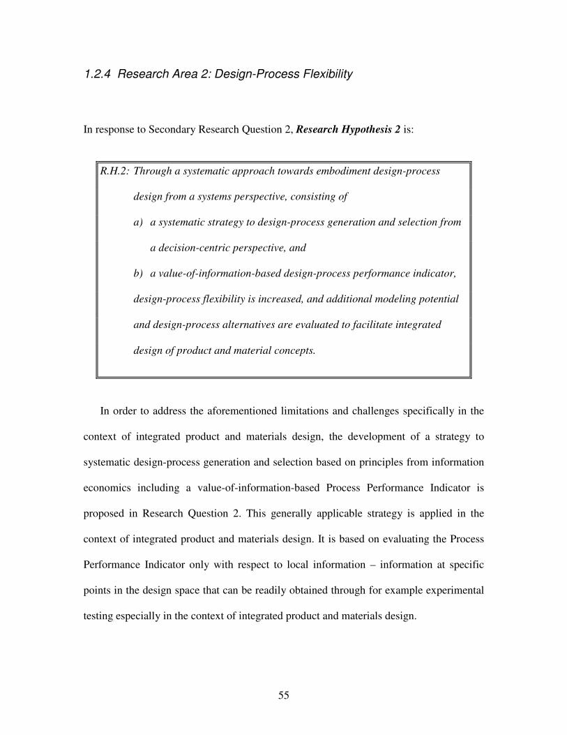
55
1.2.4 Research Area 2: Design-Process Flexibility
In response to Secondary Research Question 2, Research Hypothesis 2 is:
R.H.2: Through a systematic approach towards embodiment design-process
design from a systems perspective, consisting of
a) a systematic strategy to design-process generation and selection from
a decision-centric perspective, and
b) a value-of-information-based design-process performance indicator,
design-process flexibility is increased, and additional modeling potential
and design-process alternatives are evaluated to facilitate integrated
design of product and material concepts.
In order to address the aforementioned limitations and challenges specifically in the
context of integrated product and materials design, the development of a strategy to
systematic design-process generation and selection based on principles from information
economics including a value-of-information-based Process Performance Indicator is
proposed in Research Question 2. This generally applicable strategy is applied in the
context of integrated product and materials design. It is based on evaluating the Process
Performance Indicator only with respect to local information – information at specific
points in the design space that can be readily obtained through for example experimental
testing especially in the context of integrated product and materials design.
56
In this dissertation, embodiment design-processes are modeled in terms of template-
based compromise Decision Support Problems (cDSPs) – domain-independent, modular,
reconfigurable, reusable, computer interpretable and archivable multiobjective decision
models as reviewed in detail in Section 2.1.1 – once a principal solution has been
determined in the given problem context based on phenomena and associated solution
principles. Formulating embodiment design-processes as multiobjective decisions in the
form of template-based cDSPs, each decision may be solved using more or less complex
analysis models, thereby resulting in design-process alternatives. Also, interactions
between coupled analysis models can be simplified or refined again resulting in various
design-process alternative.
Based on system performance goals and requirements, a strategy to systematically
generate design-processes (through stepwise refinement/simplification of interactions or
analysis models) and select a satisficing design-process form a decision-centric
perspective is crucial. Stepwise refinement/simplification of interactions or analysis
models for example translates to including/excluding specific phenomena or associated
solution principles on finer scales in the context of integrated product and materials
design if required for solution finding. However, the value-of-information-based strategy
to design-process generation and selection is described in greater detail in Chapter 5 as
proposed in Research Hypothesis 2.
57
1.2.5 Fundamental Research Assumptions
The fundamental assumptions on which research questions and hypotheses are based
are summarized in this section. The general assumptions are:
• a “baseline-designer” in this dissertation is a designer that does not leverage a
function-based systematic approach for integrated design of product and material
concepts – in essence a designer that follows the process described in Section
1.1.2 – and that does not make use of systematic design-process design strategies,
and
• increased concept flexibility (i.e., increased concept performance ranges, concept
functionality, concept realizability, ease of concept generation, concept variety,
concept quantity and concept novelty) as well as increased design-process
flexibility enhance a designer’s decision-making capability compared to the
“baseline-designer”.
With respect to the systematic function-based approach presented in this dissertation in
particular, fundamental assumptions are:
• accurate and sufficient information has been utilized to clarify the task,
• the system under consideration can be divided into a finite number of
subproblems represented as functions,
• a subproblem can be considered separately and its relations with other
subproblems temporarily suspended,
• subproblems and their solutions can be presented in a morphological matrix,
58
• appropriate solution-principles have been identified and the associated technology
exists to satisfy functional relationships,
• a global solution to the design problem can be found as a combination of solutions
to the individual subproblems, and
• a global solution is selected in an unbiased way.
With respect to the systematic design-process generation and selection strategy as well as
value-of-information-based Process Performance Indicator, fundamental assumptions are:
• analysis models constituting design-processes used in this dissertation have been
validated (– hence, the focus in this dissertation is not on validation, but
evaluating the value of design-process alternatives to a designer in a given
problem context form a decision-centric design perspective),
• a valid truthful analysis models (such as a detailed simulation-based analysis
models, (rapid) physical prototypes or experiments, test specimen, etc.) is known
and available to the designer,
• design-processes are used to make satisficing decisions from a decision-centric
perspective, i.e., driven by the need to improve a designer’s decision making
capability, not the necessary but more scientific need of validating analysis
models constituting design-processes,
• the appropriateness of a design-process can be strictly interpreted in terms of its
impact to overall payoff,
• the best solution in the design space occurs at the global maximum of the
expected payoff function,

59
• if utility functions are used as payoff function (as in this work), utility values must
lie between 0 and 1,
• analysis models used predict trends accurately, and
• the best solution in the design space occurs at the global maximum of the
expected payoff function.
1.2.6 Overview Research Hypotheses
Research requirements, questions and hypotheses are summarized in Table 1-1. In
Table 1-6, it is illustrated which constructs of the systematic approach and which
validation examples address the research requirements identified in Section 1.2.5. The
secondary research hypotheses and example problems are mapped to the overall
systematic approach to integrated product, materials and design-process design in the
conceptual and embodiment stage, given here as an overview in Figure 1-17 and
described in greater detail in Chapter 3. The relationship between hypotheses and
dissertation chapters is illustrated in Table 1-7.
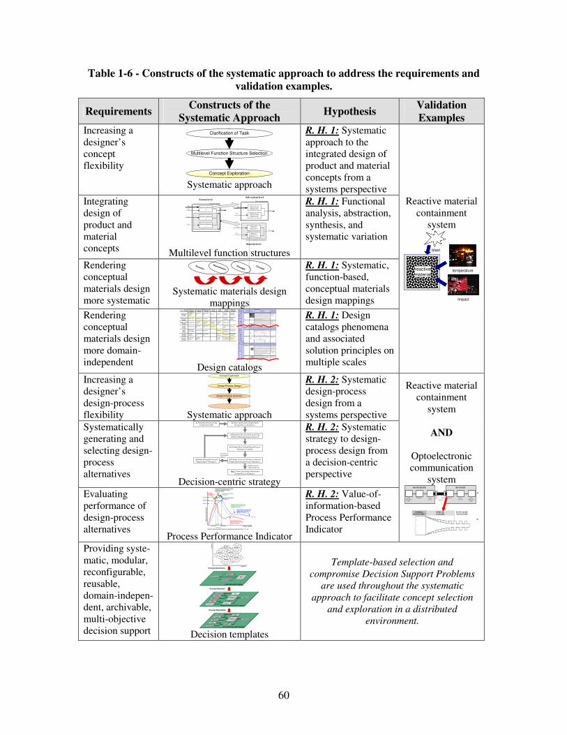
60
Table 1-6 - Constructs of the systematic approach to address the requirements and
validation examples.
Requirements Constructs of the
Systematic Approach Hypothesis
Validation
Examples Increasing a designer’s concept flexibility
Multilevel Function Structure Selection
Clarification of Task
Concept Exploration Systematic approach
R. H. 1: Systematic approach to the integrated design of product and material concepts from a systems perspective
Integrating design of product and material concepts
Advanced mult ifunctional materia l
Ex,in
Mx,in
Ex,in
System boundary
System function x Exyz,out
System function z
System function y
Ey,in
Sz,in
Mx,in Sub-system function xx
Ex,out
Sub-system function xy
Sz,in
Ey,in Material function yx
Eyz,out
Material function zx
Sub-system boundary System level
Sub-system level
Material level Multilevel function structures
R. H. 1: Functional analysis, abstraction, synthesis, and systematic variation
Rendering conceptual materials design more systematic
Systematic materials design
mappings
R. H. 1: Systematic, function-based, conceptual materials design mappings
Rendering conceptual materials design more domain-independent
Pheno-
menonScale Properties Applications
"Mon olit hic" mater ials
- M etals Co mpare d to all othe r classes of m aterial, m etals ar e stiff, stro ng and t ough, bu t
they are heavy. Th ey have relat ively high melting po in ts. Only one m etal - gold - is
chemically stable as a metal. M etals are d uctile, allowin g them to be sha ped by
rolling, for ging, dr awing n and e xt rusion. T hey are easy to ma chine with precision,
and the y ca n be joined in many diffe rent ways. Ir on and n icke l are tr ansitional
metals involving bo th meta llic and covalent bon ds, and te nd to be less ductile than other metals. However, metals cond uct electricity well, reflect light and ar e
completely opa que. Primar y produ ctio n of m etals is energ y int ensive. Many
requir e at least twice as m uch ene rgy per unit weight than commo dity polymers.
But, metals can g enera lly be recycled and the ener gy requ ir ed to d o so is much
le ss than tha t requ ried for primar y produ ction. Some ar e toxic, othe rs are so inert
that the y ca n be implan ted in the human body.
- Aluminum- , coppe r-,
magne siu m-, nickel- , steel-,
titanium- , zin c-alloys
- Carb on-, sta in les- , …
steels
- Amorp hous me tals, …
Ela
stic
/in
ela
sti
c d
efo
rm
ati
on
(te
nsio
n, co
mp
ressio
n, b
en
din
g,
sh
ear, to
rsio
n, b
ucklin
g, fr
actu
re,
cutt
ing,
inversio
n, e
xtr
usio
n,
Characteristics
Solution Principle
- Polymer s
Fr om a m acroscale, m onolithic ma terials are refer red to as matte r, i.e., th e substance of which physical objects a re com posed.
Polymer s featur e an im mense r ange o f form , color, sur face finish, translucency,
transpa rency, toug hness and flexibility. Ease of molding allows shap es that in
other mater ia ls co uld only be built up by expensive asse mbly metho ds. The ir
excellent workab ility allows the m olding of com plex for ms, allowing cheap
manufa cture o f integra ted comp onents th at pre viou sly wer e made by assembling
many par ts. Many p olym ers ar e cheap both to b uy and shap e. Most r esist water,
acids and alkalis well, thoug h orga nic solvents attack so me. All are light a nd man y
are flexible. Their p roper ties change rapidly with temp eratur e. Even at r oom
temper ature many cre ep and whe n cooled th ey may becom e brittle. Polymer s gener ally ar e sensitive to UV radiat io n and to strongly oxidizing en vir onmen ts.
- T hermo splastic polymers:
ABS, Cellulose, Ionome rs,
Nylon/ PA, PC, PEEK, PE,
PMM A, POM, PP, PS, PTFE,
tpPVC, tpPU,
PET/PET E/ PBT
- T hermo setting polyme rs:
Epo xy, Phen olic, Polyester ,
tsPU, tsPVC - Elastomer s: Acr ylic
machining.
Hone ycomb-c ore
san dwich es
- In -plane h oneycombs Co re cell axes of in -plane h oneycomb cores ar e orien ted par alle l t o the fa ce-
sheets. T hey provide potentials fo r decr eased cond uctivity a nd fluid flow within
cells. Relat ive densities ran ge fro m 0.001 to 0.3. Their d ensification stra in can be
appro xim ated as:
Their relative stiffne ss ca n be ap proximat ed as:
Their relative stre ngth can be appr oximated as:
- Prismatic-, square -,
chiracal-, etc. core in -plane
honeycom bs
- Ou t-of- plane hon eyco mbs Co re cell axes of out-of -plane h oneycomb cores ar e orient ed per pendicular to
face-she ets. Th ey provide po tentials for decrea se d conductivity. Relative den sit ie s
range from 0.001 to 0.3. T heir den sif ica tio n strain can be app roximate d as:
Their relative stiffne ss ca n be ap proximat ed as:
Their relative stre ngth can be appr oximated as:
- Hexago nal-, sqau re-, e tc.
core pu t-of- plane
honeycom bs
Fib er- compos ites
- Cont in uous fiber
comp osit es
Co ntinuous fibe r comp osit es are co mposites with highe st stiffness an d streng th.
They ar e mad e of continu ous fiber s usually embed ded in a th ermo setting re sin.
The f ib ers carr y the me chanical loads while the matrix m aterial tr ansmits loads to
the fiber s and pr ovides ductility and to ughness as well as p rotecting the fiber s
from damag e caused b y h andling or the enviro nment. It is the m atrix mat erial that
lim it s the service te mper ature a nd pro cessing conditions. On mesoscales, the prope rties can be strongly influen ced by the ch oice of fiber and m atrix and the
wa y in which t hese are combined : fiber- resin ra tio, fiber len gth, fiber orient ation,
la minate th ickn ess and the presen ce of fiber /resin cou plin g agents to impro ve
bonding. The str ength o f a comp osite is increased by raising the fiber- resin ra tio ,
and or ie nting the f ib ers par allel to the lao ding direction . Increa sed laminate
thickness leads to reduced composite strength and m odulus as the re is an
in creased likelihoo d of entr apped voids. En vir onmen tal conditions af fect the
perfor mance of comp osites: fatigue lo ading, m oist ure an d heat a ll reduce allo wab le strengt h. Po lyeste rs are the mo st most widely used m atrices as
they offer reaso nable pr operties a t relatively low cost. T he super io r pro perties o f
epoxies and the ter mper ature p erfor mance o f polyimides can ju stif y t heir use in
certain ap plica tions, but th ey are e xp ensive.
- Glass fiber s [high str ength
at low cost], polyme r fiber s
(org anic (e.g. , Kevlar ) or
anorg anic (e.g. , Nylon,
Polyester )) [r easona ble
prope rties at r elatively low cost], carb on fiber s [very high
strengt h, stiffness an d low
density]
- Strand s, fila ments, f ib ers,
ya rns (t wisted strands) ,
rovings ( bundled str ands)
- Nonwoven m attings,
we aves, bra id s, knits, other
- Discontinuo us fiber
comp osit es
Polymer s reinfo rced with chop ped polyme r, wood, g la ss or carb on fiber s are
refer red to as discontinuou s fiber com posites. T he longer the fibe r, the more
efficient is the r einforce ment a t carrying t he applied loa ds, but sho rter fibers ar e easier to process an d hence ch eaper . He nce, fiber length an d mate rial are t he
governing design var ia bles. However, fibr ous core composites f eature shape
flexibility and relatively high be nding stiffne ss at low density.
- Glass fiber s, polymer fibers
(org anic (e.g. , Kevlar ) or
anorg anic (e.g. , Nylon, Polyester )), ca rbon f ib ers
Me
so
sc
ale
Ela
stic
/in
ela
stic
def
orm
atio
n (t
ensi
on
, com
pre
ssio
n, b
en
din
g, s
hear
, tor
sion
, bu
cklin
g, fr
actu
re,
cutt
ing
, in
ver
sion
, ext
rusi
on, d
raw
ing,
flo
w)
Honeycomb -core sa ndwich es take th eir nam e from their visual r esemblan ce to a be e's honeycomb . Wit h contro llab le core dim ensions
and to pologies on m esoscales, th ey freatu re re la tive ly high stiffness and yield st rength at low density. Lar ge com pressive stra in s are
achievable a t nominally consta nt stress ( befor e the m aterial com pacts), yielding a potentially high e nergy ab so rption ca pacity. Honeycomb-
core sa ndwich es have acce ptable stru ctural pe rform ance at relatively low costs with useful com binations of therm ophysical and
mecha nical prope rties. Usually, they pr ovid e benef its with r espect to multiple use.
The combination of polyme rs or o ther m atrix ma terials with fibers h as given a r ange o f lig ht mate rials with stiffness and strengt h
compa rable to that of m etals. Comm only, resin m aterials ar e epoxies, p olye sters and vin yls. F ibers ar e much stronge r and stif fer tha n
their e quivalent in bu lk f orm b ecause the drawing pr ocess by they ar e ma de orient s the polyme r chains alon g the fiber axis or r educes th e
density of d efects.
−≈
s
D ρρ
ε 4.11
31 r el
sE
Eρ≈
rel
ys
y ρσ
σ5.0≈
rel
sE
Eρ1≈
rel
ys
y ρσ
σ1≈
−≈
s
D ρρ
ε 4.11
Design catalogs
R. H. 1: Design catalogs phenomena and associated solution principles on multiple scales
Reactive material containment
system
temperature
impact
reactive
material
blast
Increasing a designer’s design-process flexibility
Design-Process Design
…
Design-Process Selection
Concept Exploration
Systematic approach
R. H. 2: Systematic design-process design from a systems perspective
Systematically generating and selecting design-process alternatives
2) Select and Evaluate Simple Initial
Design-Process Alternative.
4) Evaluate Most Truthful Design-Process
Alternative Available.
Step 7: Select Satisficing Embodiment
Design-Process Alternative.
1) Formulate Decision Using
Compromise DSP.
3) Determine Decision Point by Solving
cDSP for Maximum Expected Payoff.
High Process Per-
formance Indicator
Low Process Performance Indicator
5) Evaluate Process Performance Indicator
Simple Initial Design-Process Alternative .
6) Refine Design-Process and
Repeat Steps 3 Through 5.
Decision-centric strategy
R. H. 2: Systematic strategy to design-process design from a decision-centric perspective
Evaluating performance of design-process alternatives
Design Variable
Ex
pe
cte
d O
ve
rall
Pa
yo
ff
Expected payoff usingdesign process alternative 1
(global information)
Expected payoff using refined design process alternative 2(global information)
Payoff 2
Decision 1 Decision 2
Payoff 1
Process Performance Indicator 1
Expected payoff using most accurate physical or simulation models(local information)
Process Performance Indicator 2
Decisions based on predicted behavior using design process alternatives 1, 2, 3, etc.
Process Performance Indicator 3
Expected payoff using refined design process alternative 3(global information)
Payoff 3
Decision 3 Process Performance Indicator
R. H. 2: Value-of-information-based Process Performance Indicator
Reactive material containment
system
AND
Optoelectronic communication
system
Signal
(informationinput)
Modulator Source
(carrier)
Detector Signal-
processor
Signal
(informationoutput)
Input- Output-
coupling
TRANSMITTER RECEIVER
a)
b)
NORMAL
WAVEGUIDE
OPTICAL
COUPLER
SLOW-LIGHT
WAVEGUIDE
Providing syste-matic, modular, reconfigurable, reusable, domain-indepen-dent, archivable, multi-objective decision support
Concept Generation
Concept Selection
Concept Exploration
Alternatives Rank
Instantiated sDSP Template
Importance
Attributes
Goals
Preferences
Variables
Parameters
Constraints
Response
Objective
Analysis
Driver
Fully Instantiated cDSP Template
Goals
Preferences
Variables
Parameters
Constraints
Response
Objective
Analysis
Driver
Partially Instantiated cDSP Template
Att
rib
ute
2
Attribute 1
Concept 2
Concept 5
Concept 1 Concept 3
Concept 6
Concept 4
Decision templates
Template-based selection and
compromise Decision Support Problems
are used throughout the systematic
approach to facilitate concept selection
and exploration in a distributed
environment.
Output
Input
Mechanical
Energy
(In)elastic de-
formation
Inertia
…
Electrostric-
tion
…
Magnetostric-
tion
…
Impact
…
Friction
…
Pressure
change
…
Dislocation
hardening
…
Electrostatic
Energy
Electric field
…
Interference
…
Hall-effect
…
Electrostric-
tion
…
Photostric-
tion
…
Electrical
resistance
…
Galvanic
element
…
Magnetostatic
Energy
Magnetic field
…
Oscillating
circuit
…
Ferromag-
netism
…
Magneto-
striction
…
Farraday-
effect
…
Eddy current
…
Sound
Energy
Pressure wave
…
Electrostric-
tion
…
Magnetostric-
tion
…
Reflection
…
Noise dam-
ping
…
Elasticity
…
Light
Energy
Electromag-
netic radiation…
Photostric-tion…
Absorption…
Refraction…
Thermolumi-
nescence…
Photoeffect…
Thermal
Energy
Thermal
expansion
…
Thermoelectri
city
…
Curie-Weiss
law
…
Pyro-
electricity
…
Convection
…
Phase trans-
formation
…
Molecular
Energy
Exothermic
reaction
…
Molecular
dipoloe
…
Fluores-
cence
…
Combustion
Conductivity
…
Adhesion
…
Light
Energy
Thermal
Energy
Molecular
Energy
Mechanical
Energy
Electrostatic
Energy
Magnetostatic
Energy
Sound
Energy
Concept
Principle
Phenomenon
Function
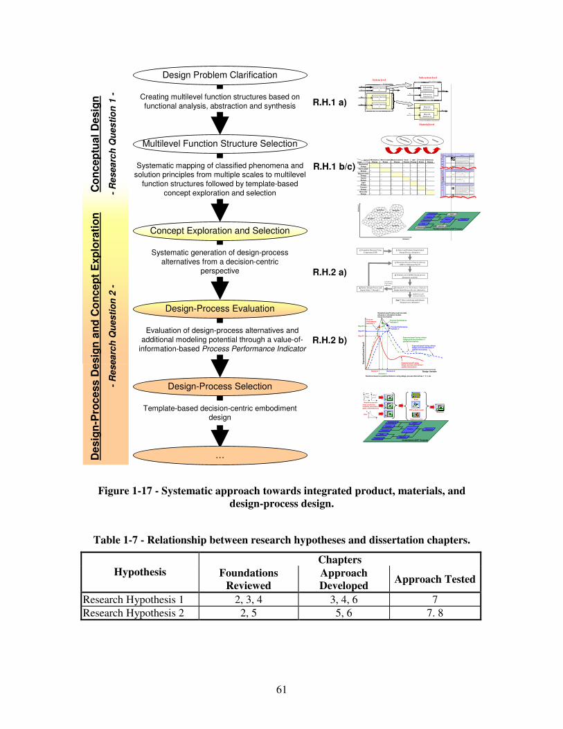
61
Template-based decision-centric embodiment design
Evaluation of design-process alternatives and
additional modeling potential through a value-of-
information-based Process Performance Indicator
Multilevel Function Structure Selection
Design Problem Clarification
Design-Process Evaluation
Design-Process Selection
Concept Exploration and Selection
Co
nc
ep
tual
Desig
n
-R
esea
rch
Qu
es
tio
n 1
- Creating multilevel function structures based on
functional analysis, abstraction and synthesis
Systematic mapping of classified phenomena and solution principles from multiple scales to multilevel
function structures followed by template-based
concept exploration and selection
Systematic generation of design-process
alternatives from a decision-centric
perspective
De
sig
n-P
roc
ess D
esig
n a
nd
Co
nce
pt
Ex
plo
rati
on
-R
esea
rch
Qu
es
tio
n 2
-
OutputInput
Mechanical
Energy… … … … … … …
Electrostatic
Energy… … … … … …
MagnetostaticEnergy
… … … … … …
Sound
Energy… … … … … …
Light
Energy… … … … … …
Thermal
Energy… … … … … …
Molecular
Energy… … … … … …
Light
Energy
Thermal
Energy
Molecular
Energy
Mechanical
Energy
Electrostatic
Energy
Magnetostatic
Energy
Sound
Energy
Advanced multifunctional material
Ex,in
Mx,in
Ex,in
System boundary
System function x Exyz,out
System function z
System function y
Ey,in
Sz,in
Mx,in Sub-system function xx
Ex,out
Sub-system function xy
Sz, in
Ey,in Material function yx
Eyz,out
Material function zx
Sub-system boundarySystem level
Sub-system level
Material level
R.H.1 a)
R.H.2 a)
R.H.1 b/c)
R.H.2 b)
Design Variable
Exp
ecte
d O
vera
ll P
ay
off
Expected payoff usingdesign process alternative 1(global information)
Expected payoff using refined design process alternative 2(global information)
Payoff 2
Decision 1 Decision 2
Payoff 1
Process Performance Indicator 1
Expected payoff using most accurate physical or simulation models(local information)
Process Performance Indicator 2
Decisions based on predicted behavior using design process alternatives 1, 2, 3, etc.
Process Performance Indicator 3
Expected payoff using refined design process alternative 3(global information)
Payoff 3
Decision 3
Goals
Preferences
Variables
Parameters
Constraints
Response
Objective
Analysis
Driver
Instantiated cDSP Template
Driver
BRP analysis model
Response
core
front
backσ σ
εε
Blast
A
t
Other constraints, variables, parameters, goals, and preferences
Material properties
Objective function
Pheno-
menonScale Properties Applications
"Monolithic" m at erials
- Metals Compared to all other classes of material, metals are stiff, str ong and tough, but they are heavy. They have relatively high melting points. Only one metal - gold - is chemically stable as a metal. Metals are ductile, allowing them to be shaped by
rolling, forging, draw ingn and extrusion. They are easy to machine with precision, and they can be joined in many different w ays. Iron and nickel are transitional metals involving both metallic and covalent bonds, and tend to be less ductile than
other metals. However, metals conduct electr icity w ell, reflect light and are completely opaque. P rimar y production of metals is energy intensive. Many requir e at least tw ice as much energy per unit weight than commodity polymers.
But, metals can generally be recycled and the energy r equired to do so is much less than that requried for primary production. Some are toxic, others ar e so inert that they can be implanted in the human body.
- Aluminum-, copper -, magnesium- , nickel-, steel-, titanium-, zinc-alloys
- Carbon-, stainles-, … steels - Amorphous metals, …
Ela
sti
c/i
ne
las
tic
def
orm
ati
on
(te
ns
ion
, c
om
pre
ss
ion
, b
en
din
g,
sh
ea
r, t
ors
ion
, b
uc
kli
ng
, fr
ac
ture
, c
utt
ing
, in
ve
rsio
n, e
xtr
us
ion
,
Characteristics
Solution Principle
- Polymer s
From a macr oscale, monolithic materials are referred to as matter, i.e., the substance of which physical objects are composed.
Polymers feature an immense r ange of form, color, surface finish, translucency, transparency, toughness and flexibility. Ease of molding allows shapes that in
other materials could only be built up by expensive assembly methods. Their excellent w orkability allow s the molding of complex forms, allowing cheap manufacture of integrated components that previously were made by assembling
many parts. Many polymers are cheap both to buy and shape. Most resist w ater, acids and alkalis well, though organic solvents attack some. A ll are light and many are flexible. Their properties change rapidly w ith temperature. Even at room
temperature many cr eep and when cooled they may become brittle. P olymers gener ally ar e sensitive to UV radiation and to strongly oxidizing environments.
- Thermosplastic polymers: ABS, C ellulose, Ionomers,
Nylon/PA , PC, P EEK, P E, PMMA, POM, P P, PS, P TFE, tpP VC, tpPU ,
PET/PE TE/PB T - Thermosetting polymers: Epoxy, Phenolic, Polyester,
tsP U, tsPVC - Elastomers: Acrylic
machining.
Ho neycom b-core
sandwiches
- In-plane honeycombs Core cell axes of in-plane honeycomb cores ar e or iented parallel to the face-sheets. They provide potentials for decreased conductivity and fluid flow within cells. Relative densities range from 0.001 to 0.3. Their densification strain can be
appr oximated as:
Their relative stiffness can be approximated as:
Their relative strength can be approximated as:
- Prismatic-, squar e- , chiracal- , etc. core in-plane honeycombs
- Out-of-plane honeycombs Core cell axes of out-of-plane honeycomb cores are oriented perpendicular to face-sheets. T hey provide potentials for decr eased conductivity. Relative densities
range fr om 0.001 to 0.3. T heir densification strain can be approximated as:
Their relative stiffness can be approximated as:
Their relative strength can be approximated as:
- Hexagonal-, sqaure-, etc. core put-of-plane
honeycombs
Fiber- co mposites
- C ontinuous fiber
composites
Continuous fiber composites are composites with highest stiffness and strength.
They are made of continuous fibers usually embedded in a thermosetting resin. The fibers carry the mechanical loads while the matrix mater ial transmits loads to the fibers and pr ovides ductility and toughness as well as protecting the fibers
from damage caused by handling or the environment. It is the matrix material that limits the service temperature and processing conditions. On mesoscales, the properties can be strongly influenced by the choice of fiber and matrix and the
way in w hich these are combined: fiber-resin r atio, fiber length, fiber or ientation, laminate thickness and the pr esence of fiber/resin coupling agents to improve bonding. The str ength of a composite is incr eased by raising the fiber-resin r atio,
and orienting the fibers par allel to the laoding direction. Increased laminate thickness leads to reduced composite strength and modulus as there is an increased likelihood of entr apped voids. Environmental conditions affect the performance of composites: fatigue loading, moisture and heat all
reduce allowable strength. Polyesters are the most most w idely used matrices as they offer reasonable properties at relatively low cost. The superior properties of epoxies and the termperature per formance of polyimides can justify their use in
cer tain applications, but they are expensive.
- Glass fibers [high strength
at low cost], polymer fibers (organic (e.g., Kevlar) or anorganic (e.g., N ylon,
Polyester)) [reasonable pr operties at relatively low cost], car bon fibers [very high
strength, stiffness and low density] - Strands, filaments, fibers,
yarns (twisted strands), rovings (bundled strands) - Nonwoven mattings, weaves, braids, knits, other
- D iscontinuous fiber composites
Polymers reinforced w ith chopped polymer , w ood, glass or carbon fibers ar e referred to as discontinuous fiber composites. The longer the fiber, the more efficient is the reinfor cement at carr ying the applied loads, but shorter fibers are
easier to process and hence cheaper. H ence, fiber length and mater ial are the governing design var iables. H owever, fibr ous core composites feature shape flexibility and relatively high bending stiffness at low density.
- Glass fibers, polymer fiber s (organic (e.g., Kevlar) or anorganic (e.g., N ylon,
Polyester)), carbon fibers
Mes
osc
ale
Ela
stic/in
ela
stic
deform
atio
n (
tension, c
om
pre
ss
ion, b
end
ing, s
hear, to
rsio
n, b
ucklin
g, fra
cture, cutting
, in
ve
rsio
n, extru
sio
n, d
raw
ing,
flow
)
Honeycomb-core sandwiches take their name from their visual resemblance to a bee's honeycomb. W ith controllable core dimensions and topologies on mesoscales, they freature r elatively high stiffness and yield strength at low density. Large compressive strains ar e achievable at nominally constant stress (before the material compacts), yielding a potentially high energy absorption capacity. H oneycomb-
core sandw iches have acceptable structural per for mance at relatively low costs w ith useful combinations of thermophysical and mechanical properties. Usually, they provide benefits w ith respect to multiple use.
The combination of polymers or other matrix materials w ith fibers has given a range of light materials with stiffness and strength compar able to that of metals. C ommonly, resin materials are epoxies, polyesters and vinyls. F ibers are much stronger and stiffer than their equivalent in bulk form because the drawing process by they ar e made orients the polymer chains along the fiber axis or reduces the
density of defects.
−≈
s
D ρ
ρε 4.11
31 re l
sE
E ρ≈
rel
ys
y ρσ
σ5.0≈
rel
sE
E ρ1≈
rel
ys
y ρσ
σ1≈
−≈
s
D ρ
ρε 4.11
…
2) Select and Evaluate Simple Initial
Design Process Alternative.
4) Evaluate most truthful design process
alternative available.
Step 7: Select satisficing embodiment
design process alternative.
1) Formulate Decision Using
Compromise DSP.
3) Determine Decision Point by Solving
cDSP for Maximum Payoff.
High Process Per-
formance Indicator
Low Process
Performance
Indicator
5) Evaluate Process Performance Indicator
Simple Initial Design-Process Alternative .
6) Refine Design-Process and
Repeat Steps 3 Through 5.
Goals
PreferencesPreferences
Variables
Parameters
Constraints
Response
ObjectiveObjective
Analysis
DriverDriver
Partially Instantiated cDSP Template
Att
rib
ute
2
Attribute 1
Concept 2
Concept 5
Concept 1 Concept 3
Concept 6
Concept 4
Concept
Principle
Phenomenon
Function
Figure 1-17 - Systematic approach towards integrated product, materials, and
design-process design.
Table 1-7 - Relationship between research hypotheses and dissertation chapters.
Chapters Hypothesis Foundations
Reviewed
Approach
Developed Approach Tested
Research Hypothesis 1 2, 3, 4 3, 4, 6 7
Research Hypothesis 2 2, 5 5, 6 7. 8
62
1.2.7 Research Contributions
As described in Section 1.1, the main contribution in this dissertation is the
development of a function-based systematic approach towards the integrated design of
products, advanced multifunctional materials, and associated embodiment design
processes from a systems perspective, i.e., based on a holistic understanding of the
scientific phenomena and principles at multiple levels and scales. The focus in this
research is thus on:
• enabling a designer to systematically determine and frame material and product
concepts and their most significant properties in an integrated fashion from a
systems perspective, and
• evaluating additional modeling potential and design-process alternatives from a
systems perspective.
Specific contributions in this research include:
• a systematic approach to allow for function-based systematic design of material
and product concepts as well as associated embodiment design-process from a
systems perspective in an integrated fashion to enhance a designer’s concept and
design-process flexibility,
• a systematic approach to integrated conceptual product and materials design
through functional analysis, abstraction, synthesis, and systematic variation from
a systems perspective,
• a systematic approach to make the conceptual design of advanced multifunctional
materials on multiple scales more systematic and domain-independent, hence less
63
ad-hoc and intuitive, through systematic mappings of phenomena and associated
solution principles,
• a systematic strategy to generating design-process alternatives from a decision-
centric perspective,
• a value-of-information-based Process Performance Indicator,
• design catalogs classifying phenomena and associated solution principles
(structure-property relations) on multiple scales in order to facilitate systematic
mappings of phenomena and associated governing solution principles from
multiple disciplines to multilevel function structures, in order facilitate integrated
design of product and material concepts from a systems perspective, as well as in
order to make materials design more domain-independent,
• concept selection charts to visualize concept flexibility and map performance
ranges of specific concepts or solution principles as attention-directing tools
during conceptual design,
• extensions to the design domain itself by extending the applicability of systematic
conceptual design methodologies to the domain of materials design, thereby
increasing designer’s concept flexibility,
• extensions to the materials domain by introducing function-based systematic
conceptual materials design, and
• extensions to the field of design-process design by developing a value-of-
information-based Process Performance Indicator to evaluate additional modeling
potential and performance of design-process alternatives, thereby increasing a
designer’s design-process flexibility.
64
Based on these contributions a designer now has the following abilities the baseline
designer did not have before:
• designing materials in a systematic fashion during the conceptual design phase
facilitated through design catalogs,
• designing products and materials in a function-based, systematic, integrated
fashion from a systems perspective and mapping performance ranges in concept
selection charts, and
• designing associated embodiment design-processes by systematically generating
design-process alternatives and evaluating their performance and the potential for
additional modeling especially in the context of integrated product and materials
design.
Therefore, crucial to this dissertation are:
i) the new interpretation to materials structure-property relations and their
classification in design catalogs facilitating conceptual design of materials in a
new, systematic, function-based way, and
ii) the systematic strategy to generate and select embodiment design-process
alternatives from a decision-centric perspective and associated value-of-
information-based Process Performance Indicator enabling a designer to generate,
evaluate, and select embodiment design-processes and in a new way.
Overall, this dissertation is particularly useful for the early phases of integrated product
and materials design, and many other scenarios in systematic product or materials design.
Even though shortcomings of several state of the art product, material, and design-
process design methodologies are addressed in the proposed systematic approach towards
65
the integrated design of products, advanced multifunctional materials, and associated
embodiment design-processes, it would of course be impudent to claim full integration of
product, materials and design process design through this research. However, the goal of
this research is to further narrow the existing gap as much as possible and bring the body
of knowledge a step further.
The systematic approach towards integrated design of products, advanced
multifunctional materials, and associated embodiment design-processes from a systems
perspective is validated using example problems in different domains:
i) the design of reactive material containment systems, and
ii) the design of waveguides for an optoelectronic communication system. However,
potential applications are numerous and compelling, and not limited to the two addressed
in this dissertation. More details on the validation strategy used in this dissertation are
described in the following Section.
1.3 Validation Strategy
A primary concern in any research effort is the validation and verification of the
proposed approach and the achieved results. The validation and verification strategy for
this research is based on the validation square introduced by Pedersen and coauthors
[497, 583] and illustrated in Figure 1-18.
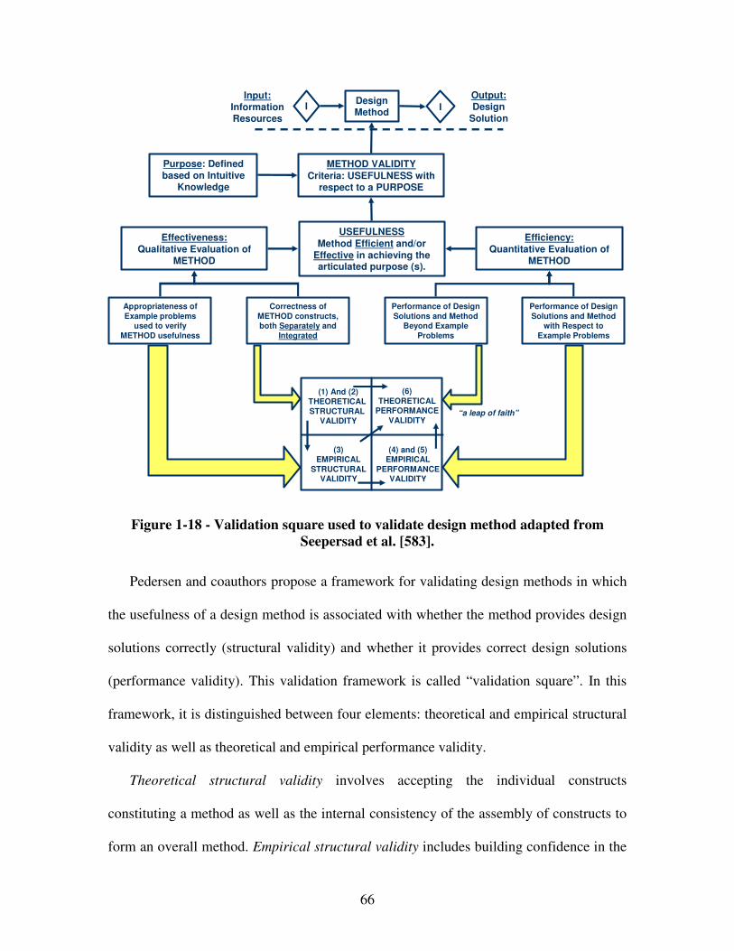
66
Design Method
Purpose: Defined based on Intuitive
Knowledge
METHOD VALIDITYCriteria: USEFULNESS with
respect to a PURPOSE
USEFULNESSMethod Efficient and/or
Effective in achieving the articulated purpose (s).
Efficiency:Quantitative Evaluation of
METHOD
Effectiveness:Qualitative Evaluation of
METHOD
Appropriateness of Example problems
used to verify METHOD usefulness
Correctness of METHOD constructs, both Separately and
Integrated
Performance of Design Solutions and Method
Beyond Example Problems
Performance of Design Solutions and Method
with Respect to Example Problems
(1) And (2)THEORETICAL STRUCTURAL
VALIDITY
(6)THEORETICAL
PERFORMANCEVALIDITY
(4) and (5)EMPIRICAL
PERFORMANCEVALIDITY
(3)EMPIRICAL
STRUCTURALVALIDITY
“a leap of faith”
I IInput:
InformationResources
Output:Design
Solution
Figure 1-18 - Validation square used to validate design method adapted from
Seepersad et al. [583].
Pedersen and coauthors propose a framework for validating design methods in which
the usefulness of a design method is associated with whether the method provides design
solutions correctly (structural validity) and whether it provides correct design solutions
(performance validity). This validation framework is called “validation square”. In this
framework, it is distinguished between four elements: theoretical and empirical structural
validity as well as theoretical and empirical performance validity.
Theoretical structural validity involves accepting the individual constructs
constituting a method as well as the internal consistency of the assembly of constructs to
form an overall method. Empirical structural validity includes building confidence in the
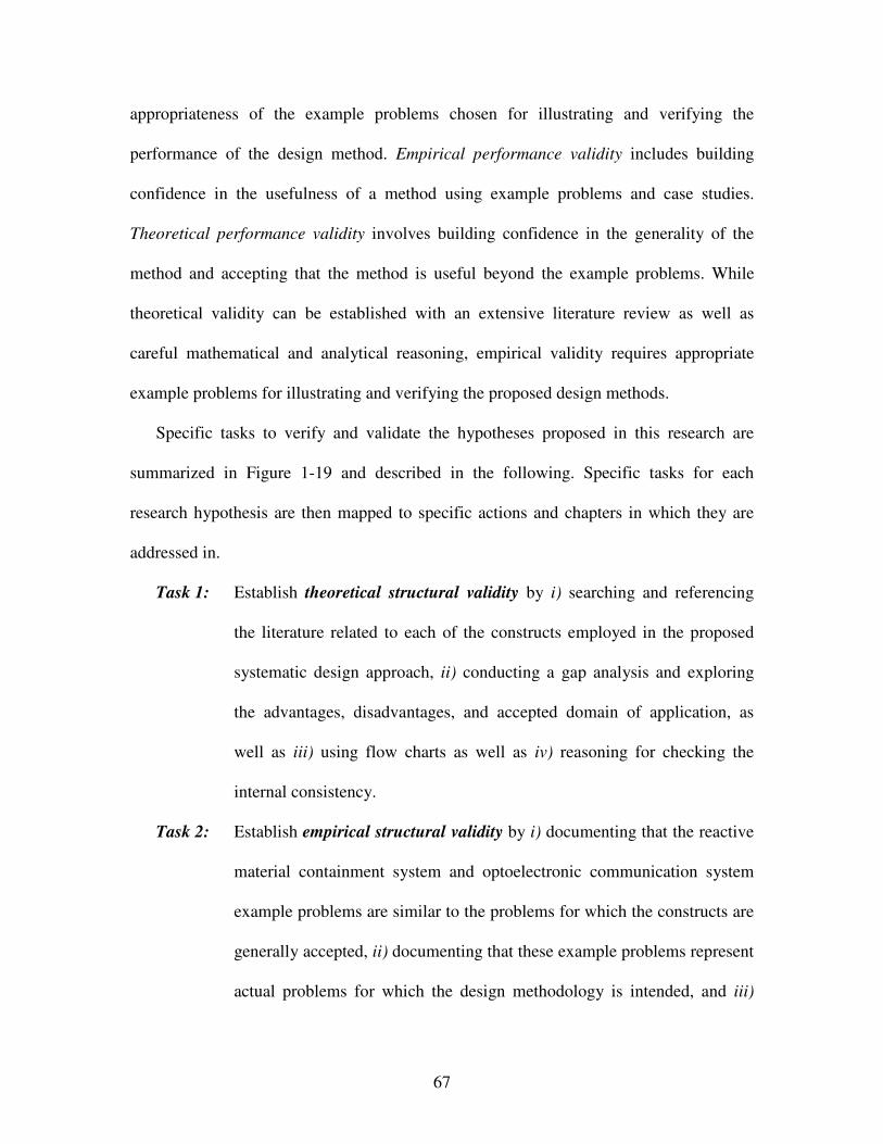
67
appropriateness of the example problems chosen for illustrating and verifying the
performance of the design method. Empirical performance validity includes building
confidence in the usefulness of a method using example problems and case studies.
Theoretical performance validity involves building confidence in the generality of the
method and accepting that the method is useful beyond the example problems. While
theoretical validity can be established with an extensive literature review as well as
careful mathematical and analytical reasoning, empirical validity requires appropriate
example problems for illustrating and verifying the proposed design methods.
Specific tasks to verify and validate the hypotheses proposed in this research are
summarized in Figure 1-19 and described in the following. Specific tasks for each
research hypothesis are then mapped to specific actions and chapters in which they are
addressed in.
Task 1: Establish theoretical structural validity by i) searching and referencing
the literature related to each of the constructs employed in the proposed
systematic design approach, ii) conducting a gap analysis and exploring
the advantages, disadvantages, and accepted domain of application, as
well as iii) using flow charts as well as iv) reasoning for checking the
internal consistency.
Task 2: Establish empirical structural validity by i) documenting that the reactive
material containment system and optoelectronic communication system
example problems are similar to the problems for which the constructs are
generally accepted, ii) documenting that these example problems represent
actual problems for which the design methodology is intended, and iii)
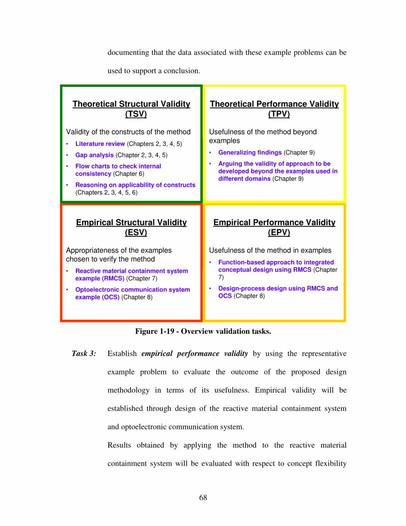
68
documenting that the data associated with these example problems can be
used to support a conclusion.
(Domain Independent)
Theoretical
Structural
Validity
(Domain Independent)
Theoretical
Performance
Validity
(Domain Specific)
Empirical Structural
Validity
(Domain Specific)
Empirical Performance
Validity
(Domain Independent)
Theoretical
Structural
Validity
(Domain Independent)
Theoretical
Performance
Validity
(Domain Specific)
Empirical Structural
Validity
(Domain Specific)
Empirical Performance
Validity
Empirical Performance Validity (EPV)
Usefulness of the method in examples
• Function-based approach to integrated conceptual design using RMCS (Chapter
7)
• Design-process design using RMCS and OCS (Chapter 8)
Empirical Structural Validity (ESV)
Appropriateness of the examples
chosen to verify the method
• Reactive material containment system example (RMCS) (Chapter 7)
• Optoelectronic communication system example (OCS) (Chapter 8)
Theoretical Performance Validity (TPV)
Usefulness of the method beyond
examples
• Generalizing findings (Chapter 9)
• Arguing the validity of approach to be developed beyond the examples used in different domains (Chapter 9)
Theoretical Structural Validity (TSV)
Validity of the constructs of the method
• Literature review (Chapters 2, 3, 4, 5)
• Gap analysis (Chapter 2, 3, 4, 5)
• Flow charts to check internal consistency (Chapter 6)
• Reasoning on applicability of constructs (Chapters 2, 3, 4, 5, 6)
Figure 1-19 - Overview validation tasks.
Task 3: Establish empirical performance validity by using the representative
example problem to evaluate the outcome of the proposed design
methodology in terms of its usefulness. Empirical validity will be
established through design of the reactive material containment system
and optoelectronic communication system.
Results obtained by applying the method to the reactive material
containment system will be evaluated with respect to concept flexibility
69
indicators set forth previously in the context of Research Hypothesis 1. To
accept that usefulness is linked to applying the method, usefulness will be
evaluated by looking at the collective group of indicators.
For Research Hypothesis 2, analytical and more or less complex finite-
element analysis models for the reactive material containment system and
optoelectronic communication system will be used to assess the usefulness
of the proposed design-process design strategy. The utility of the
systematic approach to design-process design is demonstrated by
answering the following questions:
• Is the strategy for generating design-process alternatives from a
decision-centric perspective helpful in increasing speed and ease of
information gathering used for decision making without affecting a
designer’s decision making capability, i.e., quality of decision-
making?
• Is the value-of-information-based Process Performance Indicator
suitable for making meta-level decisions such as evaluating
performance of design-process alternatives especially in the context of
integrated product and materials design?
Having demonstrated utility of the systematic approach, the observed
usefulness is linked to the constructs developed in this dissertation and
verified using numerical results obtained from the examples scenarios.
Task 4: Establish theoretical performance validity by showing that the design
methodology is useful beyond the reactive material containment system

70
and optoelectronic communication system example problem. This
involves i) showing that the example problem is representative of a
general class of problems and ii) strengthening confidence in the design
methodology by generalizing findings. From success in tasks 1 to 3 and
logic, the general usefulness of the method can be inferred. Although a
case for generality may be made, every validation strategy ultimately
relies on a “leap of faith” [497].
71
Table 1-8 - Validation tasks.
Theoretical Structural Validation
Tasks Actions Sections 1 i): Searching and referencing the literature related to each of the constructs
- Critical literature review function-based analysis, abstraction, synthesis, and systematic variation - Critical literature review design catalogs and case-based reasoning - Critical literature review design-process design strategies - Critical literature review information-economics, value-of-information-based design, and model selection
- 2.2.1, 3.2 - 4.2 - 2.3, 5.2 - 2.3.5, 5.2
1 ii): Conducting gap analyses
- Discussion of advantages and limitations of available approaches and identification of constructs to be used and research opportunities - Gap analysis product design - Gap analysis materials design - Gap analysis design-process design
- 3.2, 4.2, 5.2 - 2.1, 2.2, 3.2, 4.2 - 2.1.3 - 2.3, 5.2
1 iii): Using flow charts
- Flow chart of systematic approach to integrated product, materials and design-process design - Flow chart of function-based, systematic approach to the integrated design of product and material concepts - Flow chart of systematic approach to design-process design
- 6.2 - 6.2 - 6.2
1 iv): Using logic - Reasoning of internal consistency systematic approach to integrated product, materials and design-process design - Reasoning of internal consistency function-based, systematic approach to the integrated design of product and material concepts - Reasoning of internal consistency systematic approach to design-process design
- 6.4 - 3.4 - 5.6
Empirical Structural Validation
Tasks Actions Sections 2 i): Documenting that problems are accepted
- Document similarity to intended problems for which constructs of the method are generally accepted with respect to the reactive material containment system - Document similarity to intended problems for which constructs of the method are generally accepted with respect to the optoelectronic communication system
- 7.7 - 8.4
2 ii): Documenting usefulness of the problems for applying the method
- Document usefulness of problem reactive material containment system - Document usefulness of problem optoelectronic communication system
- 7.7 - 8.4
2 iii): Documenting usefulness of results to draw a conclusion.
- Document usefulness of data associated with reactive material containment system - Document usefulness of data associated with optoelectronic communication system
- 7.7 - 8.4
72
Table 1-8 (continued) - Validation tasks.
Empirical Performance Validation
Tasks Actions Sections 3 i): Using example problem to evaluate outcome of method
- Evaluating results of reactive material containment system with respect to concept flexibility indicators - Demonstrating utility of the systematic approach to design-process design by answering the following questions: Is the value-of-information-based strategy for generating design-process alternatives helpful in increasing speed of information gathering used for decision making without affecting a designer’s decision making capability, i.e., quality of decision-making? Is the value-of-information-based Process Performance Indicator suitable for making meta-level decisions such as evaluating performance of design-process alternatives?
- 7.5.2, 7.7 - 7.5.2, 7.7, 8.4
3 ii): Linking results to applying the method
- Evaluating results of reactive material containment system with respect to the collective group of concept flexibility indicators - Linking observed usefulness of the reactive material containment system and optoelectronic communication system to the constructs developed in this dissertation and verification using numerical results obtained from the examples scenarios
- 7.7 - 7.5.2, 7.7, 8.4
Theoretical Structural Validation
Tasks Actions Sections 4 i): Showing that example problems are representative
- Showing that the reactive material containment system and optoelectronic communication system examples are representative of a general class of problems
- 9.2
4 ii): Strengthen-ing confidence in method
- Strengthening confidence in method by generalizing findings
- 9.2
The organization of the dissertation based on the validation square is shown in Figure
1-20. An organization of the dissertation in terms of a roadmap is described in the
following section.
73
Figure 1-20 - Organization of the dissertation based on the validation square.
1.4 Organization of Dissertation
An overview of the dissertation is presented as a roadmap in order to help readers
navigating through this dissertation and developing an overall picture of what will be
discussed and how it will be presented shown in Figure 1-21.
Theoretical Structural
Validity
Empirical Structural
Validity
Theoretical Performance
Validity
Empirical Performance
Validity
Chapter 6 Chapter 2
Chapter 8
Chapter 9
Chapter 1
Chapter 3
Problem Identification
Premises of Theory and Method
Background
Example 1: Reactive material containment system
Theoretical Foundations
Closure
Chapter 5
Chapter 4
Function-based approach to the integrated design of product and material concepts
Systematic strategy to design-process design based on information economics featuring a value-of-information-based Process Performance Indicator
Design catalogs pheno-mena and associated solution principles
Summary of the systematic approach to integrated product, materials, and design-process design
Chapter 7
Example 2: Optoelectronic communication system
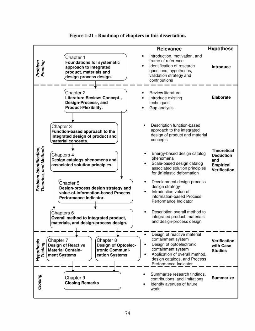
74
Figure 1-21 - Roadmap of chapters in this dissertation.
Chapter 1 Foundations for systematic approach to integrated product, materials and design-process design.
• Introduction, motivation, and frame of reference
• Identification of research questions, hypotheses, validation strategy and contributions
Pro
ble
m
Fra
min
g
Chapter 2 Literature Review: Concept-, Design-Process-, and Product-Flexibility.
• Review literature
• Introduce existing techniques
• Gap analysis
Relevance Hypotheses
Introduce
Elaborate
Chapter 3 Function-based approach to the integrated design of product and material concepts.
• Description overall method to integrated product, materials and design-process design
Theoretical Deduction and Empirical Verification
Chapter 7 Design of Reactive Material Contain-ment Systems
• Development design-process design strategy
• Introduction value-of-information-based Process Performance Indicator
• Design of reactive material containment system
• Design of optoelectronic containment system
• Application of overall method, design catalogs, and Process Performance Indicator
Chapter 9 Closing Remarks
• Summarize research findings, contributions, and limitations
• Identify avenues of future work
Summarize
Pro
ble
m Id
en
tifi
cati
on
, T
heo
ries
, an
d M
eth
od
s
Clo
sin
g
Chapters 6 Overall method to integrated product, materials, and design-process design.
• Energy-based design catalog phenomena
• Scale-based design catalog associated solution principles for (in)elastic deformation
Verification with Case Studies
Chapters 4 Design catalogs phenomena and associated solution principles.
Chapter 8 Design of Optoelec-tronic Communi-cation Systems
• Description function-based approach to the integrated design of product and material concepts
Chapter 5 Design-process design strategy and value-of-information-based Process Performance Indicator.
Hyp
oth
esis
T
esti
ng
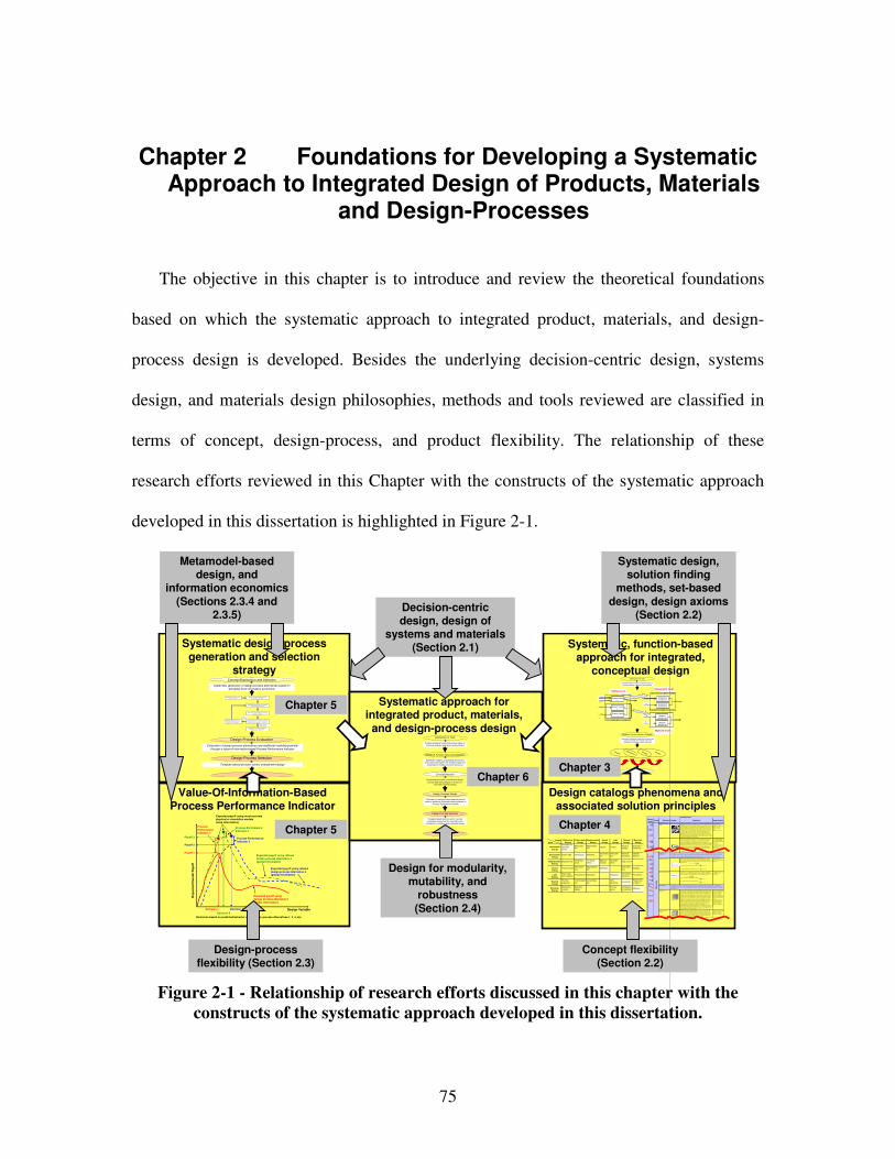
75
Chapter 2 Foundations for Developing a Systematic Approach to Integrated Design of Products, Materials
and Design-Processes
The objective in this chapter is to introduce and review the theoretical foundations
based on which the systematic approach to integrated product, materials, and design-
process design is developed. Besides the underlying decision-centric design, systems
design, and materials design philosophies, methods and tools reviewed are classified in
terms of concept, design-process, and product flexibility. The relationship of these
research efforts reviewed in this Chapter with the constructs of the systematic approach
developed in this dissertation is highlighted in Figure 2-1.
Systematic design-process generation and selection
strategy
Value-Of-Information-Based Process Performance Indicator
Systematic approach for integrated product, materials,
and design-process design
Design catalogs phenomena and associated solution principles
Systematic, function-based approach for integrated,
conceptual design
Systematic mapping of c lassified phenomena and solution principles from multiple scales and disciplines to multilevel function structures
Creating multilevel function structures based on functional analysis, abstraction and synthesis
Ex, in
Mx,in
Ex,i n
System boundary
System function x Exyz,out
System function z
System function y
Ey,i n
Sz, in
Mx,in Sub-system function xx
Ex,out
Sub-system function xy
Sz, in
Ey,in Material function yx
Eyz,out
Material function zx
Sub-system boundarySystem level
Sub-system level
Material level
Clarification of Task
Multilevel Function Structure Selection
Concept Selection
Concept
Principle
Phenomenon
Function
Pheno-menon
Scale Properties Applications
"M onoli thic" materials
- Metals Compared to all other c lasses of material, m etals are stif f, strong and tough, but they are heavy. They have relativel y high melt ing points. Onl y one metal - gold - is chemically stable as a metal. Metals are ductile, allowing them to be shaped by rolling, forging, drawi ngn and ext rusion. They are easy to machine with precision,
and they can be joined in m any different ways. I ron and nickel are transit ional m etals involving both metallic and covalent bonds, and tend to be l ess ductile than other m etals. However, m etals conduct electrici ty well, ref lect light and are completely opaque. Prim ary producti on of metals is energy intensive. M any
requi re at least twice as m uch energy per unit weight than comm odity polym ers. But, metals can generally be recycled and the energy requi red to do so is m uch l ess than that requried for prim ary producti on. Some are toxic, others are so inert that they can be im pl anted i n the human body.
- A lum inum -, copper-, magnesium-, nickel-, steel-, titanium-, zinc-alloys - Carbon-, stainles-, …
steels - Amorphous m etals, …
Ela
sti
c/i
nela
sti
c d
efo
rmati
on
(te
nsio
n, co
mpre
ssio
n,
ben
din
g, s
hea
r, to
rsio
n, b
uck
lin
g, fr
actu
re, cu
ttin
g,
inv
ers
ion,
extr
us
ion
,
Characteristics
Solution Principle
- Polymers
From a m acroscale, monolithic materials are referred to as matter, i.e., the substance of which physical obj ects are composed.
Polymers feature an immense range of form , color, surface finish, t ranslucency, t ransparency, toughness and f lexibilit y. Ease of m olding allows shapes that in other m aterials could only be built up by expensive assem bly methods. Their
excellent workability allows the molding of complex form s, allowing cheap m anufacture of i ntegrated com ponents that previously were made by assembling m any parts. Many polym ers are cheap both to buy and shape. Most resist water, acids and alkalis well, though organic solvents attack som e. Al l are light and many
are f lexible. T heir properties change rapidly with temperature. Even at room temperature many creep and when cooled they m ay become britt le. Polymers generally are sensit ive to UV radiat ion and to strongly oxidiz ing environments.
- Thermosplast ic polymers: ABS, Cellulose, Ionomers, Nylon/PA, PC, PEEK, PE,
PMMA, POM, PP, PS, PTFE, tpPVC, tpPU, PET /PETE/PBT - Thermosett ing polymers:
Epoxy, Phenolic, Polyester, tsPU, tsPVC - E lastomers: Acrylic
m achining.
Honeycomb-core sandwiches
- In-plane honeycombs Core cell axes of in-plane honeycomb cores are ori ented paral lel to the face-
sheets. They provide potentials for decreased conduct ivit y and f luid flow within cells. Relative densities range from 0.001 to 0.3. Thei r densi ficat ion st rain can be approximated as:
T heir relative st iffness can be approxi mated as:
T heir relative st rength can be approximated as:
- P rismatic-, square-,
chiracal-, etc. core in-plane honeycombs
- Out -of -plane honeycombs Core cell axes of out-of-plane honeycomb cores are ori ented perpendicular to
face-sheets. They provi de potentials for decreased conductivi ty. Relat ive densit ies range from 0.001 to 0.3. T heir densif icati on strain can be approximated as:
T heir relative st iffness can be approxi mated as:
T heir relative st rength can be approximated as:
- Hexagonal-, sqaure-, etc.
core put-of -plane honeycombs
Fiber-composi tes
- Continuous f iber com posites
Continuous f iber composites are composites with highest stif fness and strength. T hey are made of cont inuous fibers usuall y embedded in a therm osett ing resin. T he fibers carry the mechanical loads while the mat rix m aterial transmits l oads to the fibers and provides ductilit y and toughness as well as protecting the fibers
f rom damage caused by handling or the environment . It is the matrix material that l imits the service temperature and processing conditions. On m esoscal es, the properties can be strongly inf luenced by the choice of fiber and matrix and the way in which these are combined: fiber-resin ratio, fi ber length, fiber orientation,
l am inate thickness and the presence of fiber/resin coupling agents to im prove bonding. The strength of a composite is increased by raisi ng the fiber-resin rati o, and orient ing the f ibers parallel to the laoding direct ion. Increased laminate thickness leads to reduced composite st rength and modul us as there is an
i ncreased likelihood of entrapped voids. Environmental condit ions affect the performance of composi tes: fat igue l oading, m oisture and heat all reduce allowable strength. Polyesters are the most most widely used matrices as they offer reasonable propert ies at relat ively low cost. The superi or properties of
epoxies and the termperature performance of polyimides can justif y their use in certain applications, but they are expensive.
- Glass fibers [high strength at low cost] , polymer fibers (organic (e.g., Kevlar) or anorganic (e.g., Nylon,
Polyester)) [ reasonable propert ies at rel at ively low cost], carbon fibers [very hi gh st rength, st iffness and low
density] - S trands, f ilaments, f ibers, yarns (twisted st rands), rovings (bundled strands)
- Nonwoven mat tings, weaves, braids, knits, other
- Discontinuous f iber com posites
Polymers reinforced with chopped polym er, wood, glass or carbon f ibers are referred to as discont inuous fiber com posites. The longer the fiber, the more ef fic ient is the reinforcement at carrying the applied loads, but shorter f ibers are
easier to process and hence cheaper. Hence, fi ber length and material are the governing design variabl es. However, f ibrous core composi tes feature shape f lexibilit y and relatively high bending stif fness at low density.
- Glass fibers, polymer fibers (organic (e.g., Kevlar) or anorganic (e.g., Nylon,
Polyester)), carbon f ibers
Mesoscale
Ela
sti
c/in
ela
sti
c d
efo
rm
ation
(te
nsio
n, co
mpre
ssio
n, b
end
ing
, sh
ear,
torsio
n, b
ucklin
g, fr
ac
ture
, cu
ttin
g, in
vers
ion, extr
usio
n, d
raw
ing
,
flow
)
Honeycomb-core sandwiches take their name f rom their visual resemblance to a bee's honeycomb. With cont rollable core dim ensions
and topol ogies on mesoscales, they freature relatively high stif fness and yield strength at low density. Large com pressive st rains are achievable at nom inally constant stress (before the material compacts), y ieldi ng a potent ial ly high energy absorpti on capacity. Honeycomb-core sandwiches have acceptable structural performance at relat ively low costs with useful combinations of thermophysical and mechanical propert ies. Usually, they provide benef its with respect to multi ple use.
The com bi nati on of polymers or other m atrix materials with fibers has given a range of light materi als with st iffness and strength com parable to that of metals. Commonly, resin materials are epoxi es, polyesters and vinyls. Fibers are much stronger and st iffer than their equi valent in bulk form because the drawing process by they are made orients the polymer chains along the fiber axis or reduces the density of defects.
−≈
s
D
ρ
ρε 4.11
31 rel
sE
Eρ≈
rel
y s
yρ
σ
σ5.0≈
rel
sE
Eρ1≈
re l
ys
y ρσ
σ1≈
−≈
s
D ρ
ρε 4.11
Output
Input
Mechanical
Energy
(In)elastic de-
formation
Inertia…
Electrostric-tion
…
Magnetostric-tion
…
Impact
…
Friction
…
Pressure change
…
Dislocation hardening
…
Electrostatic
Energy
Electric field
…
Interference
…
Hall-effect
…
Electrostric-
tion…
Photostric-
tion…
Electrical
resistance…
Galvanic
element…
Magnetostatic
Energy
Magnetic field
…
Oscillating
circuit…
Ferromag-
netism…
Magneto-
striction…
Farraday-
effect…
Eddy current
…
Sound
Energy
Pressure wave
…
Electrostric-
tion
…
Magnetostric-
tion
…
Reflection
…
Noise dam-
ping
…
Elasticity
…
Light
Energy
Electromag-
netic radiation
…
Photostric-tion
…
Absorption
…
Refraction
…
Thermolumi-
nescence
…
Photoeffect
…
Thermal
Energy
Thermal
expansion
…
Thermoelectri
city
…
Curie-Weiss
law
…
Pyro-
electricity
…
Convection…
Phase trans-
formation
…
Molecular
Energy
Exothermic
reaction
…
Molecular
dipoloe
…
Fluores-
cence
…
Combustion
Conductivity
…
Adhesion…
Light
Energy
Thermal
Energy
Molecular
Energy
Mechanical
Energy
Electrostatic
Energy
Magnetostatic
Energy
Sound
Energy
Design Variable
Exp
ecte
d O
ve
rall
Pa
yo
ff
Expected payoff usingdesign process alternative 1(global information)
Expected payoff using refined design process alternative 2(global information)
Payoff 2
Decision 1 Decision 2
Payoff 1
Process Performance Indicator 1
Expected payoff using most accurate physical or simulation models(local information)
Process Performance Indicator 2
Decisions based on predicted behavior using design process alternatives 1, 2, 3, etc.
Process Performance Indicator 3
Expected payoff using refined design process alternative 3(global information)
Payoff 3
Decision 3
Template-based decision-centric concept exploration accounting for uncertainty and
complexity of multilevel and multiscale design
Evaluation of design-process alternatives and value of additional multiscale modeling based on
Process Performance Indicator
Multilevel Function Structure Selection
Clarification of Task
Design-Process Design
Embodiment Design
Design-Process Selection
Concept Selection
Creating multilevel function structures based on functional analysis, abstraction and synthesis
Systematic mapping of classified phenomena and solution principles from multiple scales and
disciplines to multilevel function structures
Systematic generation of multiscale design-
process alternatives based on a value-of-information-based strategy
Evaluation of design-process alternatives and additional modeling potential
through a value-of-information-based Process Performance Indicator
Systematic generation of design-process alternatives based on
principles from information economics
Design-Process Evaluation
Design-Process Selection
Concept Exploration and Selection
Template-based decision-centric embodiment design
2) Select and Evaluate Simple Initial
Design Process Alternative.
4) Evaluate most truthful design process
alternative available.
Step 7: Select satisficing embodiment
design process alternative.
1) Formulate Decision Using
Compromise DSP.
3) Determine Decision Point by Solving
cDSP for Maximum Payof f.
High Process Per-formance Indicator
Low Process
Performance Indicator
5) Evaluate Process Performance Indicator
Simple Initial Design-Process Alternative .
6) Refine Design-Process and
Repeat Steps 3 Through 5.
…
Decision-centric design, design of
systems and materials (Section 2.1)
Design-process flexibility (Section 2.3)
Systematic design, solution finding
methods, set-based design, design axioms
(Section 2.2)
Metamodel-based design, and
information economics(Sections 2.3.4 and
2.3.5)
Concept flexibility (Section 2.2)
Design for modularity, mutability, and
robustness (Section 2.4)
Chapter 5
Chapter 5
Chapter 6Chapter 3
Chapter 4
Figure 2-1 - Relationship of research efforts discussed in this chapter with the
constructs of the systematic approach developed in this dissertation.
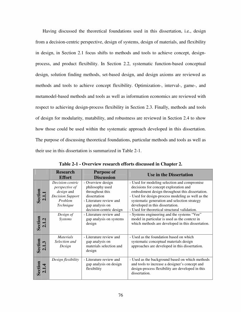
76
Having discussed the theoretical foundations used in this dissertation, i.e., design
from a decision-centric perspective, design of systems, design of materials, and flexibility
in design, in Section 2.1 focus shifts to methods and tools to achieve concept, design-
process, and product flexibility. In Section 2.2, systematic function-based conceptual
design, solution finding methods, set-based design, and design axioms are reviewed as
methods and tools to achieve concept flexibility. Optimization-, interval-, game-, and
metamodel-based methods and tools as well as information economics are reviewed with
respect to achieving design-process flexibility in Section 2.3. Finally, methods and tools
of design for modularity, mutability, and robustness are reviewed in Section 2.4 to show
how those could be used within the systematic approach developed in this dissertation.
The purpose of discussing theoretical foundations, particular methods and tools as well as
their use in this dissertation is summarized in Table 2-1.
Table 2-1 - Overview research efforts discussed in Chapter 2.
Research
Effort
Purpose of
Discussion Use in the Dissertation
Sec
tio
n
2.1
.1
Decision-centric
perspective of
design and Decision Support
Problem
Technique
- Overview design philosophy used throughout this dissertation
- Literature review and gap analysis on decision-centric design
- Used for modeling selection and compromise decisions for concept exploration and embodiment design throughout this dissertation.
- Used for design-process modeling as well as the systematic generation and selection strategy developed in this dissertation.
- Used for theoretical structural validation.
Sec
tio
n
2.1
.2
Design of
Systems
- Literature review and gap analysis on systems design
- Systems engineering and the systems “Vee” model in particular is used as the context in which methods are developed in this dissertation.
Sec
tio
n
2.1
.3
Materials
Selection and
Design
- Literature review and gap analysis on materials selection and design
- Used as the foundation based on which systematic conceptual materials design approaches are developed in this dissertation.
Sec
tio
n
2.1
.4
Design flexibility - Literature review and gap analysis on design flexibility
- Used as the background based on which methods and tools to increase a designer’s concept and design-process flexibility are developed in this dissertation.
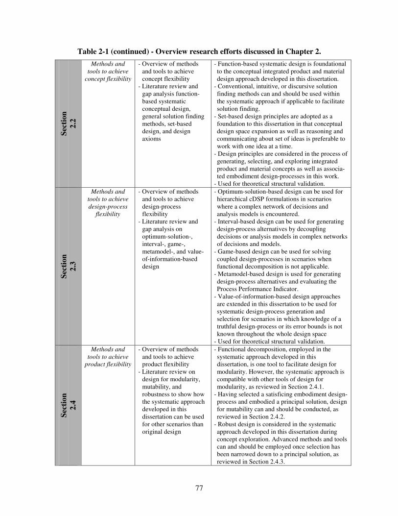
77
Table 2-1 (continued) - Overview research efforts discussed in Chapter 2.
Sec
tio
n
2.2
Methods and
tools to achieve
concept flexibility
- Overview of methods and tools to achieve concept flexibility
- Literature review and gap analysis function-based systematic conceptual design, general solution finding methods, set-based design, and design axioms
- Function-based systematic design is foundational to the conceptual integrated product and material design approach developed in this dissertation.
- Conventional, intuitive, or discursive solution finding methods can and should be used within the systematic approach if applicable to facilitate solution finding.
- Set-based design principles are adopted as a foundation to this dissertation in that conceptual design space expansion as well as reasoning and communicating about set of ideas is preferable to work with one idea at a time.
- Design principles are considered in the process of generating, selecting, and exploring integrated product and material concepts as well as associa-ted embodiment design-processes in this work.
- Used for theoretical structural validation.
Sec
tio
n
2.3
Methods and
tools to achieve
design-process
flexibility
- Overview of methods and tools to achieve design-process flexibility
- Literature review and gap analysis on optimum-solution-, interval-, game-, metamodel-, and value-of-information-based design
- Optimum-solution-based design can be used for hierarchical cDSP formulations in scenarios where a complex network of decisions and analysis models is encountered.
- Interval-based design can be used for generating design-process alternatives by decoupling decisions or analysis models in complex networks of decisions and models.
- Game-based design can be used for solving coupled design-processes in scenarios when functional decomposition is not applicable.
- Metamodel-based design is used for generating design-process alternatives and evaluating the Process Performance Indicator.
- Value-of-information-based design approaches are extended in this dissertation to be used for systematic design-process generation and selection for scenarios in which knowledge of a truthful design-process or its error bounds is not known throughout the whole design space
- Used for theoretical structural validation.
Sec
tio
n
2.4
Methods and
tools to achieve
product flexibility
- Overview of methods and tools to achieve product flexibility
- Literature review on design for modularity, mutability, and robustness to show how the systematic approach developed in this dissertation can be used for other scenarios than original design
- Functional decomposition, employed in the systematic approach developed in this dissertation, is one tool to facilitate design for modularity. However, the systematic approach is compatible with other tools of design for modularity, as reviewed in Section 2.4.1.
- Having selected a satisficing embodiment design-process and embodied a principal solution, design for mutability can and should be conducted, as reviewed in Section 2.4.2.
- Robust design is considered in the systematic approach developed in this dissertation during concept exploration. Advanced methods and tools can and should be employed once selection has been narrowed down to a principal solution, as reviewed in Section 2.4.3.
78
2.1 Theoretical Foundations Used in this Dissertation
In this section, theoretical foundations of the systematic approach developed in this
dissertation are reviewed. Template-based decision-centric design reviewed in Section
2.1.1 is used throughout this dissertation for modeling design-processes for concept
exploration and embodiment design as well as design-process design. Systems design is
reviewed in Section 2.1.2 and used in this dissertation as the context in which methods
are developed. Materials selection and design approaches are reviewed in Section 2.1.3.
Existing research efforts in materials design are used as the foundation based on which
systematic conceptual materials design approaches are developed in this dissertation.
Finally, design flexibility is reviewed as the background based on which methods and
tools to increase a designer’s concept and design-process flexibility are developed in this
dissertation.
2.1.1 Design-Process Modeling – a Template-Based Decision-Centric Perspective
In contrast to natural sciences that are concerned with how things are, design on the
other hand is concerned with how things ought to be [596], one form of art. Design can
be described as the interface between art and science, i.e., the interface between the
verities of science and innate or intuitive skills of art [441]. It draws its strength from the
rationality of classical science and the intuition of art. Therefore, in the literature, a
primary and secondary creativity have been introduced to describe this two sidedness of
79
design [52, 348]. On the one hand, primary creativity deals with intuitive thinking,
strongly associated with flashes of inspiration. On the other hand, secondary creativity
involves discursive thinking, a conscious process, that can be communicated and
influenced, in which scientific knowledge and relationships are consciously analyzed,
varied, combined in new ways, checked, rejected, and considered further.
This dissertation is based on template-based decision-centric design. The fundamental
assumption is that decisions and information transformations (analysis models) are used
to make better decisions from a systems perspective. Hence, modeling efforts are driven
by the need to improve decision making capability. This decision-centric design
philosophy implemented in domain-independent templates [205, 434, 475] is described in
the following.
The template-based approach for modeling design decisions and interactions between
distributed decision makers in a reusable, adaptive and extendable form leverages three
key ideas: i) design processes themselves are hierarchical systems, ii) separation of
declarative and procedural information enhances reusability of design processes, and iii)
design is a decision-centric activity. These are discussed in detail in the following.
Hierarchical Systems View of Design-Processes
From a hierarchical systems standpoint, design-processes can be progressively broken
down into sub-processes that in turn can be represented in terms of basic design-process
building blocks. Hence, from a decision-centric perspective [475], design-processes are
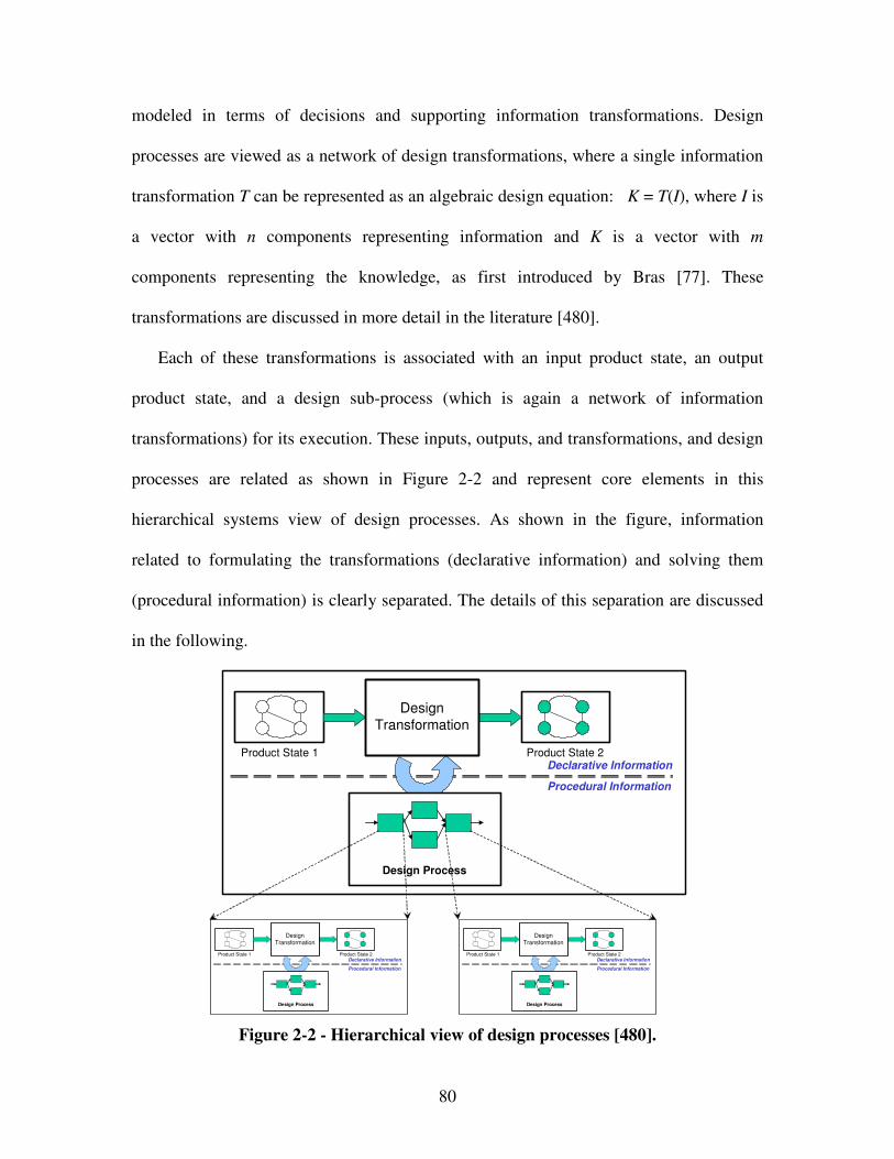
80
modeled in terms of decisions and supporting information transformations. Design
processes are viewed as a network of design transformations, where a single information
transformation T can be represented as an algebraic design equation: K = T(I), where I is
a vector with n components representing information and K is a vector with m
components representing the knowledge, as first introduced by Bras [77]. These
transformations are discussed in more detail in the literature [480].
Each of these transformations is associated with an input product state, an output
product state, and a design sub-process (which is again a network of information
transformations) for its execution. These inputs, outputs, and transformations, and design
processes are related as shown in Figure 2-2 and represent core elements in this
hierarchical systems view of design processes. As shown in the figure, information
related to formulating the transformations (declarative information) and solving them
(procedural information) is clearly separated. The details of this separation are discussed
in the following.
Product State 1 Product State 2
DesignTransformation
Declarative Information
Procedural Information
Design Process
Product State 1 Product State 2
DesignTransformation
Declarative Information
Procedural Information
Design Process
Product State 1 Product State 2
DesignTransformation
Declarative Information
Procedural Information
Design Process
Figure 2-2 - Hierarchical view of design processes [480].
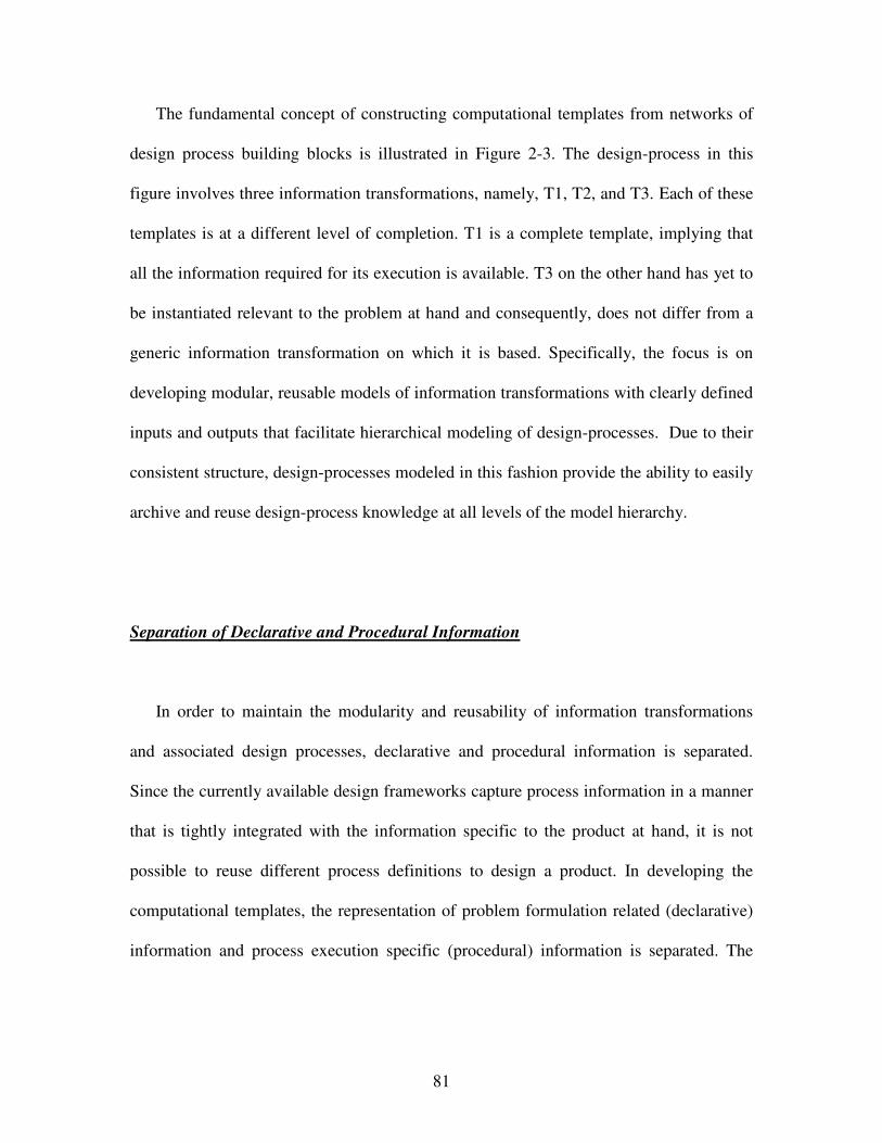
81
The fundamental concept of constructing computational templates from networks of
design process building blocks is illustrated in Figure 2-3. The design-process in this
figure involves three information transformations, namely, T1, T2, and T3. Each of these
templates is at a different level of completion. T1 is a complete template, implying that
all the information required for its execution is available. T3 on the other hand has yet to
be instantiated relevant to the problem at hand and consequently, does not differ from a
generic information transformation on which it is based. Specifically, the focus is on
developing modular, reusable models of information transformations with clearly defined
inputs and outputs that facilitate hierarchical modeling of design-processes. Due to their
consistent structure, design-processes modeled in this fashion provide the ability to easily
archive and reuse design-process knowledge at all levels of the model hierarchy.
Separation of Declarative and Procedural Information
In order to maintain the modularity and reusability of information transformations
and associated design processes, declarative and procedural information is separated.
Since the currently available design frameworks capture process information in a manner
that is tightly integrated with the information specific to the product at hand, it is not
possible to reuse different process definitions to design a product. In developing the
computational templates, the representation of problem formulation related (declarative)
information and process execution specific (procedural) information is separated. The
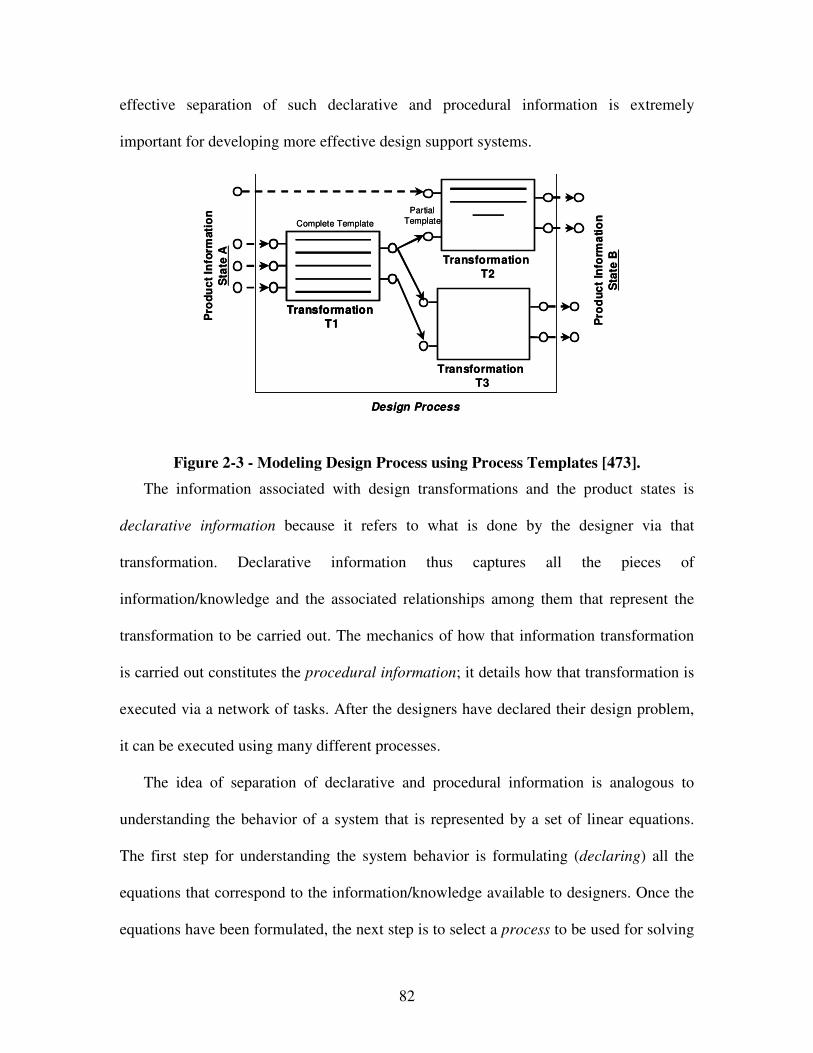
82
effective separation of such declarative and procedural information is extremely
important for developing more effective design support systems.
Pro
du
ct
Info
rmati
on
Sta
te A
Pro
du
ct
Info
rma
tio
n
Sta
te B
Transformation
T1
Transformation
T2
Transformation
T3
Design Process
Complete Template
Partial
Template
Pro
du
ct
Info
rmati
on
Sta
te A
Pro
du
ct
Info
rma
tio
n
Sta
te B
Transformation
T1
Transformation
T1
Transformation
T2
Transformation
T3
Design Process
Complete Template
Partial
Template
Figure 2-3 - Modeling Design Process using Process Templates [473].
The information associated with design transformations and the product states is
declarative information because it refers to what is done by the designer via that
transformation. Declarative information thus captures all the pieces of
information/knowledge and the associated relationships among them that represent the
transformation to be carried out. The mechanics of how that information transformation
is carried out constitutes the procedural information; it details how that transformation is
executed via a network of tasks. After the designers have declared their design problem,
it can be executed using many different processes.
The idea of separation of declarative and procedural information is analogous to
understanding the behavior of a system that is represented by a set of linear equations.
The first step for understanding the system behavior is formulating (declaring) all the
equations that correspond to the information/knowledge available to designers. Once the
equations have been formulated, the next step is to select a process to be used for solving
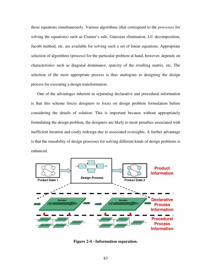
83
those equations simultaneously. Various algorithms (that correspond to the processes for
solving the equations) such as Cramer’s rule, Gaussian elimination, LU decomposition,
Jacobi method, etc. are available for solving such a set of linear equations. Appropriate
selection of algorithms (process) for the particular problem at hand, however, depends on
characteristics such as diagonal dominance, sparcity of the resulting matrix, etc. The
selection of the most appropriate process is thus analogous to designing the design
process for executing a design transformation.
One of the advantages inherent in separating declarative and procedural information
is that this scheme forces designers to focus on design problem formulation before
considering the details of solution. This is important because without appropriately
formulating the design problem, the designers are likely to incur penalties associated with
inefficient iteration and costly redesign due to associated oversights. A further advantage
is that the reusability of design processes for solving different kinds of design problems is
enhanced.
Figure 2-4 - Information separation.
ProductInformation
TransformationTransformation
Decision
TransformationTransformation
TransformationTransformationTransformationTransformation
TransformationTransformation TransformationTransformation
Decision
TransformationTransformation
TransformationTransformationTransformationTransformation
TransformationTransformation
Product State 1Product State 1 Product State 2Product State 2Design ProcessDesign Process
DeclarativeProcess
Information
ProceduralProcess
Information
84
In order to separate the declarative and procedural information in computational
decision templates, the information is separated into three levels - the product
information level, the process level, and the execution level, as shown in Figure 2-4.
In the layer corresponding to the product information level, only information, specific
to the product being designed, is captured. Since this information is treated in a
standardized manner, it can be used by different design-processes. Product information is
stored in the four templates that correspond to the declarative product information
“hidden” (or embedded) within the decision formulations, i.e., the problem definition
template, the constraints template, the goals and preferences template, and the analysis
template.
The template for defining design variables and parameters includes the following
information about design variables: i) Design Variable Name, ii) Type, iii) Unit, iv)
Value, and v) Lower Bound and Upper Bound. In the goals and preferences definition
template, information about design goals and a designer’s preferences regarding the
manner of satisfaction desired for these goals is captured. The goals are formulated with
target values for system responses. Preferences are associated with the various goals
included in the decision formulation. Here, these preferences are modeled as weights on
the deviation variables. The entities associated with such goals are: i) Name, ii) Weight,
iii) Target, and iv) Monotonicity, where monotonicity captures information regarding
whether the goal is to be maximized, minimized, or matched as closely as possible. The
constraints definition template includes information about various constraints on the
system. The constraints are associated with a name and a string representing required
mathematical operations. The analysis code is used to evaluate the system response
85
resulting from changes in design variables. The information associated with the analysis
code template includes i) Inputs, which consist of Name, Type, Unit, and Value, ii)
Outputs, which consist of Name, Type, Unit, and Value and iii) Execution. The
“Execute” field captures the software application that needs to be invoked in order to
obtain the desired system response.
In the layer, corresponding to the process level, i) required information
transformations are identified and ii) required information flows are specified in
accordance. In order to ensure complete modularity of information transformation
templates, information flows are separated from information content. Effectively a clear
distinction is made between declarative and procedural information content. In other
words, only the mechanics of information transfer are captured at this procedural level,
while problem specific information is defined separately at the declarative level. This
results in a process map that remains the same irrespective of the application in which the
process is used. Information content is thus effectively batched, according to the
structure of the overarching template.
The details of code execution are captured in the execution level layer. This level is
specific to the design problem for which the process has been instantiated. Execution
level codes interface only with the declarative problem formulation level. Thus, there is
no direct link between the process specification level and the execution level, discussed
in this section. This architecture preserves the modularity of the design processes being
modeled. It is important to note that these concepts can be implemented in virtually any
object oriented programming language and are not platform dependent.
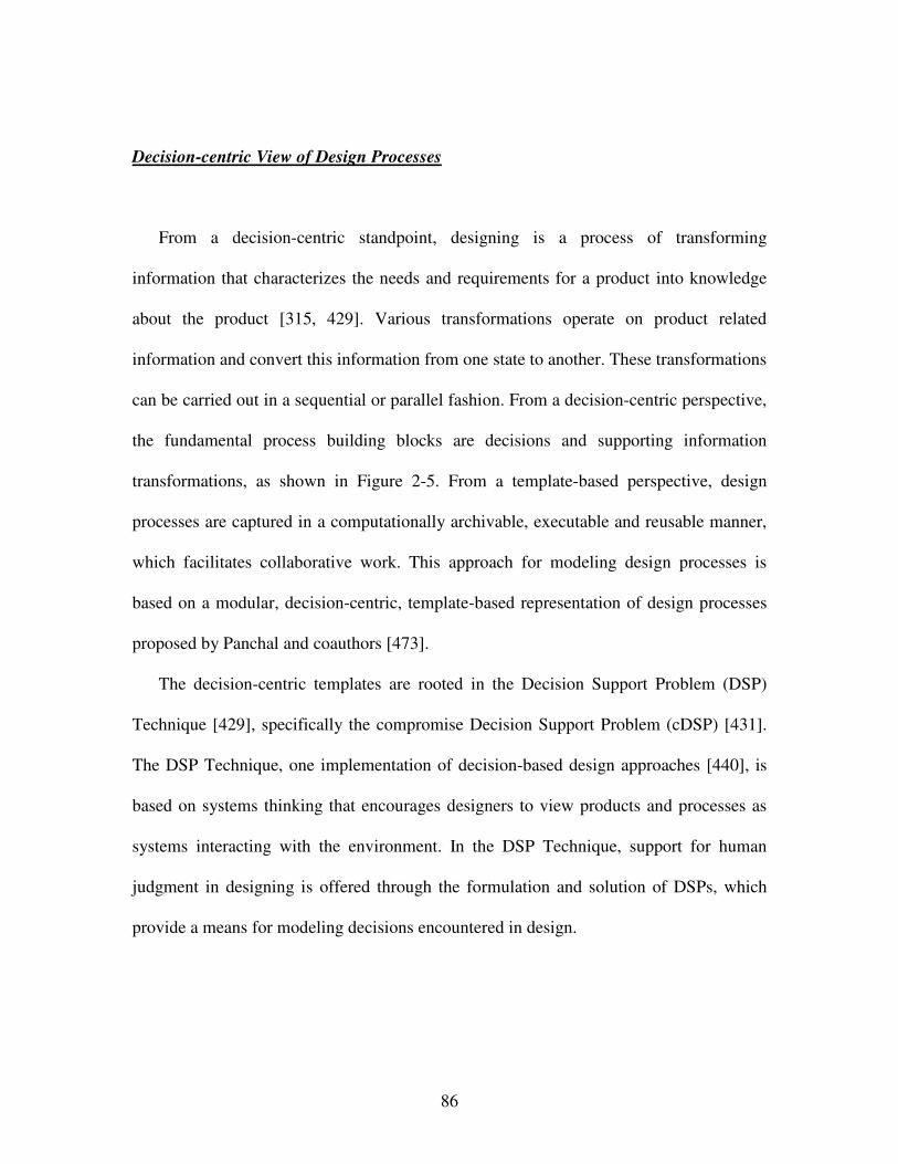
86
Decision-centric View of Design Processes
From a decision-centric standpoint, designing is a process of transforming
information that characterizes the needs and requirements for a product into knowledge
about the product [315, 429]. Various transformations operate on product related
information and convert this information from one state to another. These transformations
can be carried out in a sequential or parallel fashion. From a decision-centric perspective,
the fundamental process building blocks are decisions and supporting information
transformations, as shown in Figure 2-5. From a template-based perspective, design
processes are captured in a computationally archivable, executable and reusable manner,
which facilitates collaborative work. This approach for modeling design processes is
based on a modular, decision-centric, template-based representation of design processes
proposed by Panchal and coauthors [473].
The decision-centric templates are rooted in the Decision Support Problem (DSP)
Technique [429], specifically the compromise Decision Support Problem (cDSP) [431].
The DSP Technique, one implementation of decision-based design approaches [440], is
based on systems thinking that encourages designers to view products and processes as
systems interacting with the environment. In the DSP Technique, support for human
judgment in designing is offered through the formulation and solution of DSPs, which
provide a means for modeling decisions encountered in design.
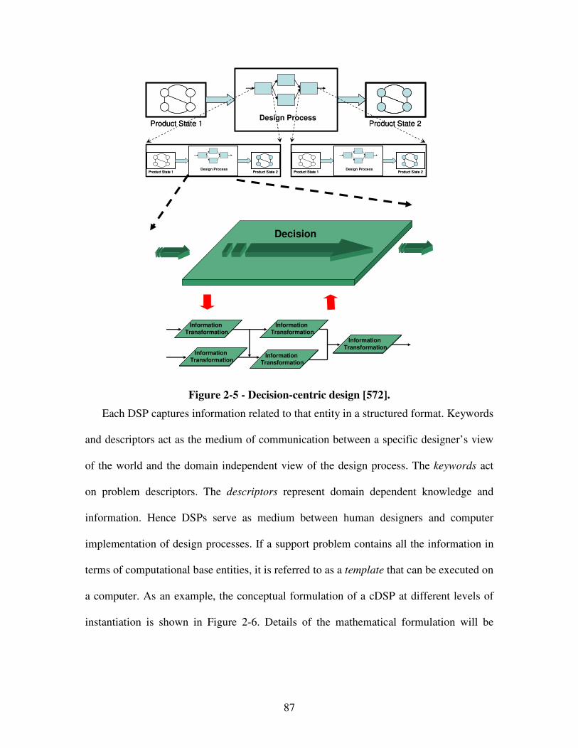
87
Product State 1Product State 1 Product State 2Product State 2Design ProcessDesign Process
Product State 1Product State 1 Product State 2Product State 2Design ProcessDesign Process
Product State 1Product State 1 Product State 2Product State 2Design ProcessDesign Process
Information Transformation
Information Transformation
Decision
Information Transformation
Information Transformation
Information Transformation
Information Transformation
Information Transformation
Information Transformation
Information Transformation
Information Transformation
Figure 2-5 - Decision-centric design [572].
Each DSP captures information related to that entity in a structured format. Keywords
and descriptors act as the medium of communication between a specific designer’s view
of the world and the domain independent view of the design process. The keywords act
on problem descriptors. The descriptors represent domain dependent knowledge and
information. Hence DSPs serve as medium between human designers and computer
implementation of design processes. If a support problem contains all the information in
terms of computational base entities, it is referred to as a template that can be executed on
a computer. As an example, the conceptual formulation of a cDSP at different levels of
instantiation is shown in Figure 2-6. Details of the mathematical formulation will be
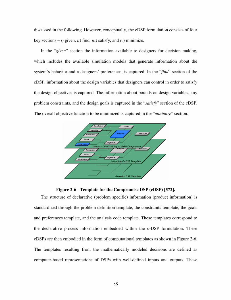
88
discussed in the following. However, conceptually, the cDSP formulation consists of four
key sections – i) given, ii) find, iii) satisfy, and iv) minimize.
In the “given” section the information available to designers for decision making,
which includes the available simulation models that generate information about the
system’s behavior and a designers’ preferences, is captured. In the “find” section of the
cDSP, information about the design variables that designers can control in order to satisfy
the design objectives is captured. The information about bounds on design variables, any
problem constraints, and the design goals is captured in the “satisfy” section of the cDSP.
The overall objective function to be minimized is captured in the “minimize” section.
Figure 2-6 - Template for the Compromise DSP (cDSP) [572].
The structure of declarative (problem specific) information (product information) is
standardized through the problem definition template, the constraints template, the goals
and preferences template, and the analysis code template. These templates correspond to
the declarative process information embedded within the c-DSP formulation. These
cDSPs are then embodied in the form of computational templates as shown in Figure 2-6.
The templates resulting from the mathematically modeled decisions are defined as
computer-based representations of DSPs with well-defined inputs and outputs. These
89
design process templates, analogously to the building block templates from which they
are composed, can be parsed, executed, stored, analyzed, and reused.
In a complicated network of decisions and supporting information transformations,
interface templates defining inputs, outputs and execution mechanisms for modeling
interactions, as shown in Figure 2-7, may serve as connectors. Modeling design-processes
with multiple decision-makers, interface templates serve as domain-independent
communications protocols for regulating the way in which experts (operating in different
functional domains) share information for effective collaboration. An interface in a
design-process separates or partitions multiple dependent or interdependent designers and
their respective design activities. As shown in Figure 2-7, interface templates serve as a
means for connecting decision templates to one another in a computer interpretable
manner. The nature of the collaboration between designers determines the form of the in-
terface.
Appropriate interface templates are developed based upon the underlying
informational dependencies between the decision makers. Consequently, the interactions
between decision makers can be easily adapted by changing the interface template. Since
the decision templates and their instantiation remains the same, the designers still control
the formulation of their own decisions. The required level of modularity is maintained via
the development of domain independent interface templates that are distinct from the
decision templates being linked.
The notion of linking various decision templates via interface templates is illustrated
in Figure 2-7, where the decisions corresponding to two design sub-problems are
instantiated as distinct cDSP templates. The information flow between the design
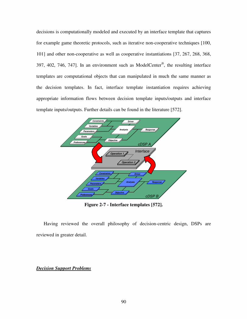
90
decisions is computationally modeled and executed by an interface template that captures
for example game theoretic protocols, such as iterative non-cooperative techniques [100,
101] and other non-cooperative as well as cooperative instantiations [37, 267, 268, 368,
397, 402, 746, 747]. In an environment such as ModelCenter®, the resulting interface
templates are computational objects that can manipulated in much the same manner as
the decision templates. In fact, interface template instantiation requires achieving
appropriate information flows between decision template inputs/outputs and interface
template inputs/outputs. Further details can be found in the literature [572].
Figure 2-7 - Interface templates [572].
Having reviewed the overall philosophy of decision-centric design, DSPs are
reviewed in greater detail.
Decision Support Problems
Interface
Goals
Preferences
Variables
Parameters
Constraints
Response
Objective
Analysis
Driver
GoalsGoals
PreferencesPreferences
VariablesVariables
ParametersParameters
ConstraintsConstraints
ResponseResponse
ObjectiveObjective
AnalysisAnalysis
DriverDriver
Goals
Preferences
Variables
Parameters
Constraints
Response
Objective
Analysis
Driver
GoalsGoals
PreferencesPreferences
VariablesVariables
ParametersParameters
ConstraintsConstraints
ResponseResponse
ObjectiveObjective
AnalysisAnalysis
DriverDriver
cDSP A
cDSP B
Operation 1Operation 1
Operation 2Operation 2
91
In general, DSPs are classified into selection and compromise decision support
problem techniques.
i) Selection Decision Support Problems
Selection occurs all along the design time-line. In the early stages, there is almost no
hard data; most of the data is soft. Moving along the design time-line, the qualitative ratio
of hard to soft information increases. Therefore, a selection process has been proposed
[434], that involves two types of selection, namely, preliminary selection followed by
selection. Preliminary selection is used to obtain the most likely to succeed concepts out
of the many concepts generated [430] based primarily on qualitative rather than
quantitative information. In other words, a preliminary selection decision support
problem is formulated and solved when the amount of experience-based soft information
far exceeds the amount of hard information available. To identify the most likely to
succeed concepts, available soft information is used to determine the more promising
most-likely-to-succeed concepts.
The functional feasibility of these most-likely-to-succeed concepts are established
and developed into candidate alternatives. The process of development is aimed at
increasing the amount of hard information that can be used to characterize the suitability
of the alternative for selection. Selection refers to decisions made to indicate a preference
for a single alternative among those which are feasible, based on their cumulative rating
weighted for their performance with respect to a selection of multiple attributes [430]. A
selection Decision Support Problem is formulated and solved when meaningful hard
92
information is available. In other words, a selection Decision Support Problem is used to
identify a very limited number of superior alternatives that should be developed further
using insight-based soft and science-based hard information. Selection is used to reduce
the number of concepts to one alternative on the basis of functional feasibility and
essential performance requirements. Consequently selection is the indication of a
preference, based on multiple attributes of varying importance, for one among several
feasible alternatives. The order indicates not only the rank but also by how much one
alternative is preferred to another.
The creation of scales and determining the relative importance plays a major role in
maintaining the integrity and quality of the selection process. The choice of a particular
type of scale to model an attribute depends on the nature of available information.
Typically, the following scales are used [45]:
• Ratio scale: Is used for an attribute for which physically meaningful numbers
are available in terms of quantitative numbers and zero has absolute value (e.g.
cost, power, speed, etc.).
• Ordinal scale: Is used to model an attribute that can only be qualified and
ranked in words (e.g. aesthetic appeal, color, etc.) or in terms of qualitative
information (e.g. excellent, good, average, poor, etc.).
• Interval scale: Is used in two ways, i.e., to model attributes in which zero is
relative (e.g. temperature, efficiency, etc.) or to transform the quality captured by
the ordinal word scale into a numerical interval scale (i.e., assigning number and
justification to an ordinal scale). Interval scales are used to specify the relative
importance of the generalized criteria or to establish the relative importance

93
between attributes and to provide a means for quantifying preferences rooted in
experience-based insight (soft information). It provides an interval or measure of
preference between ratings. A composite scale is an interval scale which is used to
model the collective preference for an entire subset of attributes at once.
The goal however is to convert the ordinal into the interval and finally into the ratio
scale. Besides these scales, nominal scales (i.e., ordinal scales that do not lead to a rank
order but groupings) and absolute scales (i.e., scales featuring absolute measurements)
are frequently used in the literature [552]. However, concerning future traceability, it is
very important to provide viewpoints (comments, justification for judgment) for each
comparison/rating. Any concept can be picked as initial datum. More than one datum
must be run (maximum seven to eight datums).
The word and mathematical formulation of the selection DSP are shown in Figure 2-8
and Figure 2-9. Steps for a selection DSP are as follows [45]:
1) Description of the alternatives and creation of acronyms
2) Description of each relevant attribute
3) Specification of the relative importance of the attributes and creation of different
scenarios by varying the relative importance of attributes.
4) Specification of scales to rate the alternatives with respect to each attribute
(allocation of ratings must be justified)
5) Normalization of ratings
6) Evaluation of the merit function for each attribute
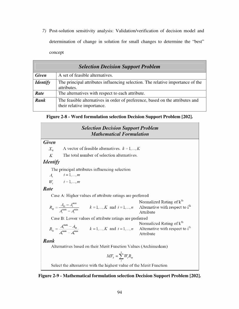
94
7) Post-solution sensitivity analysis: Validation/verification of decision model and
determination of change in solution for small changes to determine the “best”
concept
Selection Decision Support Problem
Given A set of feasible alternatives.
Identify The principal attributes influencing selection. The relative importance of the attributes.
Rate The alternatives with respect to each attribute.
Rank The feasible alternatives in order of preference, based on the attributes and their relative importance.
Figure 2-8 - Word formulation selection Decision Support Problem [202].
Figure 2-9 - Mathematical formulation selection Decision Support Problem [202].

95
To allow for more objectivity and elimination of “selection fixation”, a scale should
be created before selection begins. Evaluation should not be applied to variants in
isolation successively but each established evaluation criterion should be applied to all of
the variants in turn. Interdependence and incompleteness of the evaluation criteria should
be avoided, for example by using a checklist. In any case, value assessments and
weighting schemes are subjective and experience-based. This does not have to be a
shortcoming. Evaluation procedures are meant to enhance an engineer’s decision-making
ability. Subjective is not the same as arbitrary. Predicted parameter magnitudes, as well
as the values placed on them may however not be precise. Concerning selection, the
weighted sum formulation of the merit function restricts expression of a decision maker’s
preferences for multiple attributes and linearity of those preferences with respect to
changes in the measure of an attribute. A weighted sum formulation does not address
rigorously the risk or uncertainty associated with attributes and the alternatives they
characterize. In general, results are only as good as the information that is used and the
people who are responsible for making the recommendations.
ii) Compromise Decision Support Problems
After further development of the most promising alternative, the compromise
Decision Support Problem (cDSP) can be used. The cDSP is also derived from the
Decision Support Problem (DSP) technique, one implementation of decision-based
design approaches [440], for solving multi-objective, non-linear, optimization problems.
Mathematically the cDSP is a multi-objective decision model which is a hybrid
96
formulation based on mathematical programming [26, 542, 691] and goal programming
[25, 290-296]. The cDSP is a mathematical structure that helps human designers assess
deviation from goals/targets, while providing feed-back concerning “solution quality” in
terms specified by designer preferences [431]. The preceding serves to give a basic
understanding of the cDSP formulation. Further details can be found in a comprehensive
discussion by Mistree [431]. However, the cDSP has been successfully used in designing
aircrafts [112, 367, 431], thermal energy systems [114], mechanisms [688], structural
systems [689], ships [430], material composite design [317], aircraft engines [328],
satellite trajectories [360] and design for manufacture [498].
The compromise decision is the process of determining the “right” values or
combination of design variables (e.g., system parameters), such that the system is feasible
with respect to constraints and system performance is maximized – a particular
alternative is refined. The cDSP is structured as described in the word and mathematical
formulations shown in Figure 2-10 and Figure 2-11.
A feasible alternative is given. First step is to find system and deviation variables.
System variables are the values of the independent system variables that describe the
physical attributes of an artifact. Deviation variables are the values of the deviation
variables that indicate the extent to which the goals are achieved. In the following step,
system constraints, system goals and bounds are satisfied. Systems constraints must be
satisfied for the solution to be feasible. The product constraint ensures that one of the
deviation variables will always be zero. System goals must achieve a specified target
value as far as possible. A system goal relates the goal (aspiration level) of the designer
to the actual attainment of the goal. Multiple objectives are explicitly modeled as system
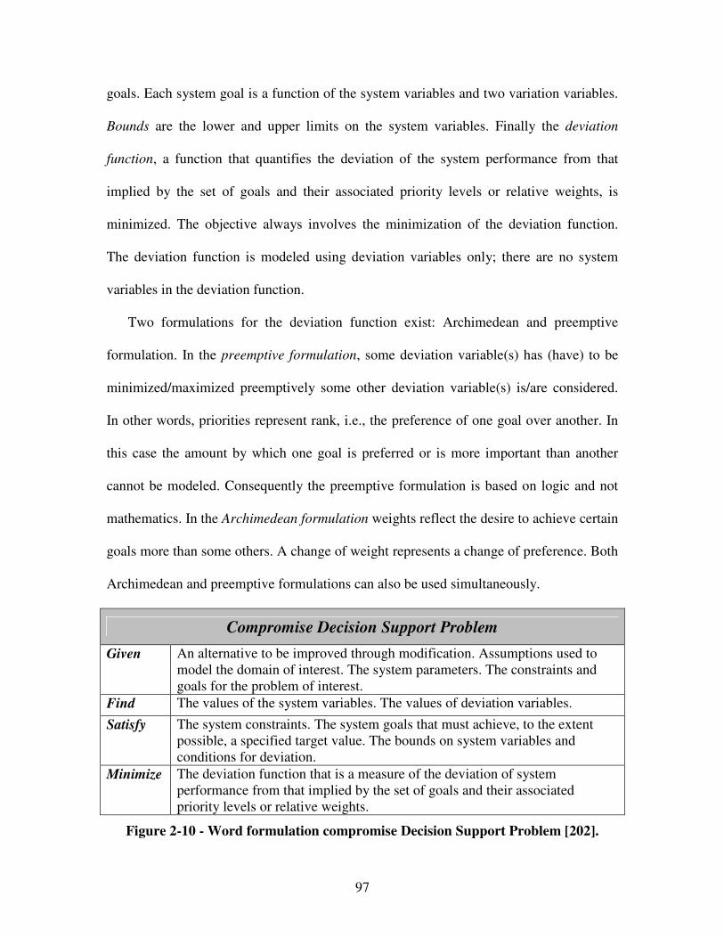
97
goals. Each system goal is a function of the system variables and two variation variables.
Bounds are the lower and upper limits on the system variables. Finally the deviation
function, a function that quantifies the deviation of the system performance from that
implied by the set of goals and their associated priority levels or relative weights, is
minimized. The objective always involves the minimization of the deviation function.
The deviation function is modeled using deviation variables only; there are no system
variables in the deviation function.
Two formulations for the deviation function exist: Archimedean and preemptive
formulation. In the preemptive formulation, some deviation variable(s) has (have) to be
minimized/maximized preemptively some other deviation variable(s) is/are considered.
In other words, priorities represent rank, i.e., the preference of one goal over another. In
this case the amount by which one goal is preferred or is more important than another
cannot be modeled. Consequently the preemptive formulation is based on logic and not
mathematics. In the Archimedean formulation weights reflect the desire to achieve certain
goals more than some others. A change of weight represents a change of preference. Both
Archimedean and preemptive formulations can also be used simultaneously.
Compromise Decision Support Problem
Given An alternative to be improved through modification. Assumptions used to model the domain of interest. The system parameters. The constraints and goals for the problem of interest.
Find The values of the system variables. The values of deviation variables.
Satisfy The system constraints. The system goals that must achieve, to the extent possible, a specified target value. The bounds on system variables and conditions for deviation.
Minimize The deviation function that is a measure of the deviation of system performance from that implied by the set of goals and their associated priority levels or relative weights.
Figure 2-10 - Word formulation compromise Decision Support Problem [202].
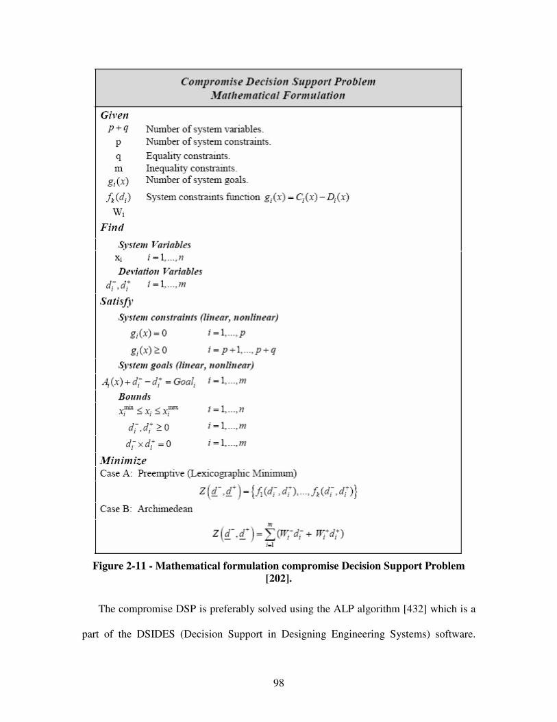
98
Figure 2-11 - Mathematical formulation compromise Decision Support Problem
[202].
The compromise DSP is preferably solved using the ALP algorithm [432] which is a
part of the DSIDES (Decision Support in Designing Engineering Systems) software.
99
However, the library of overall objective function formulations for the compromise DSP
has been expanded to include physical programming [266], Bayesion [689], fuzzy [770],
and utility theory [575] for specific contexts.
iii) Utility-Based Selection and Compromise Decision Support Problems
Utility functions are used for modeling designers’ preferences. These utility functions
are used in the compromise and selection DSP constructs for modeling design decisions.
Utility-based DSPs provide structure and support for modeling decisions that involve
compromise, selection or coupled decisions. Utility theory is used for mathematical
modeling of a decision maker´s preferences in the context of risk or uncertainty. It
provides a consistent means of numerically expressing the decision maker´s preference
when it is necessary to trade-off between multiple goals under uncertainty. In other words,
utility theory is used to facilitate decision making in product realization based on
mathematically complete principles which define ‘rational behavior’ for the decision
makers, and to derive from them the general characteristics of that behavior [697].
A decision involves the evaluation of a set of alternatives and selection of the most
preferred alternative. ‘Utility’ represents the decision maker’s preference to the outcome,
characterized with a set of attributes. In this context, an attribute is equivalent to the
response variable that measures the performance of the product. Utility values for
attributes generally lie between 0 and 1; a value of 0 denoting an unacceptable outcome
and a value of 1 denoting the most preferred outcome. “If an appropriate utility is
assigned to each possible outcome and the expected utility of the outcome for each
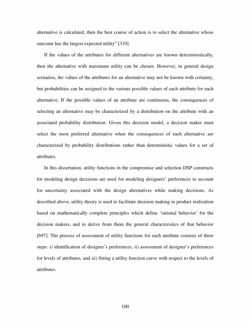
100
alternative is calculated, then the best course of action is to select the alternative whose
outcome has the largest expected utility” [319].
If the values of the attributes for different alternatives are known deterministically,
then the alternative with maximum utility can be chosen. However, in general design
scenarios, the values of the attributes for an alternative may not be known with certainty,
but probabilities can be assigned to the various possible values of each attribute for each
alternative. If the possible values of an attribute are continuous, the consequences of
selecting an alternative may be characterized by a distribution on the attribute with an
associated probability distribution. Given this decision model, a decision maker must
select the most preferred alternative when the consequences of each alternative are
characterized by probability distributions rather than deterministic values for a set of
attributes.
In this dissertation, utility functions in the compromise and selection DSP constructs
for modeling design decisions are used for modeling designers’ preferences to account
for uncertainty associated with the design alternatives while making decisions. As
described above, utility theory is used to facilitate decision making in product realization
based on mathematically complete principles which define ‘rational behavior’ for the
decision makers, and to derive from them the general characteristics of that behavior
[697]. The process of assessment of utility functions for each attribute consists of three
steps: i) identification of designer’s preferences, ii) assessment of designer’s preferences
for levels of attributes, and iii) fitting a utility function curve with respect to the levels of
attributes.
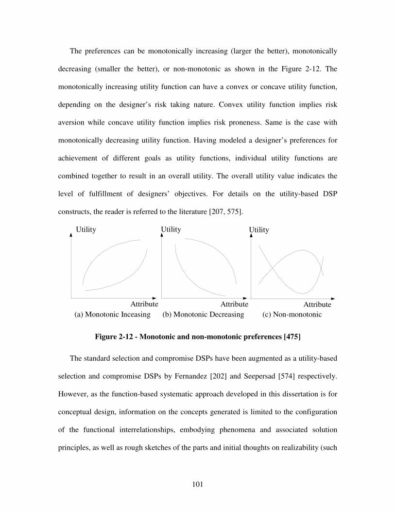
101
The preferences can be monotonically increasing (larger the better), monotonically
decreasing (smaller the better), or non-monotonic as shown in the Figure 2-12. The
monotonically increasing utility function can have a convex or concave utility function,
depending on the designer’s risk taking nature. Convex utility function implies risk
aversion while concave utility function implies risk proneness. Same is the case with
monotonically decreasing utility function. Having modeled a designer’s preferences for
achievement of different goals as utility functions, individual utility functions are
combined together to result in an overall utility. The overall utility value indicates the
level of fulfillment of designers’ objectives. For details on the utility-based DSP
constructs, the reader is referred to the literature [207, 575].
(a) Monotonic Inceasing
Attribute
Utility
(b) Monotonic Decreasing
Attribute
Utility
(c) Non-monotonic
Attribute
Utility
Figure 2-12 - Monotonic and non-monotonic preferences [475]
The standard selection and compromise DSPs have been augmented as a utility-based
selection and compromise DSPs by Fernandez [202] and Seepersad [574] respectively.
However, as the function-based systematic approach developed in this dissertation is for
conceptual design, information on the concepts generated is limited to the configuration
of the functional interrelationships, embodying phenomena and associated solution
principles, as well as rough sketches of the parts and initial thoughts on realizability (such

102
as manufacturing processes, assembly operations, resistance against environmental
effects, etc.). Feasibility of mathematical rigorous concept selection approaches in terms
of utility functions is thus limited due to the inherent lack of concrete information at these
early stages of design before detailed analysis is carried out. However, utility-based
cDSPs are leveraged in this dissertation once sufficient information on particular
constructs is available. The word and mathematical formulations of the utility-based
cDSP are shown in Figure 2-13 and Figure 2-14. Steps for a utility-based compromise
DSP are as follows:
1) Define the design problem using utility-based compromise DSP descriptors
2) Discover available information, bound the problem and identify target values
i) Provide scales for each goal (i.e., indicate how each goal is quantified)
ii) Provide bounds for each goal (i.e., indicate an ideal value of each goal and an
unacceptable value for each objective)
3) Specify levels and/or probability distributions for each objective
4) Assess utility functions for each goal
i) Identify the decision-maker;s qualitative preference characteristics for levels
of each goal (i.e., monotonic or target matching and risk avers/prone/neutral)
ii) Identify the decision-maker’s quantitative preference characteristics for levels
of each goal (i.e., five levels of each goal with specific lottery-based
definitions for each level)
iii) Fit a utility function to the decision-maker’s preferences for levels of each
goal
iv) Check the utility functions for consistency

103
5) Combine utility functions for individual goals into a multi-attribute utility
function
i) Identify relevant independence assumptions and the corresponding functional
form of the multi-attribute utility funciotn
ii) Assess scaling constant for the multi-attribute utility function
iii) Check the multi-attribute utility function for consistency
6) Formulate system goals.
7) Formulate the deviation function.
8) Post solution analysis and verification.
Utility-Based Compromise Decision Support Problem
Given An alternative to be improved through modification. Model of the domain of interest. A set of independent system variables. A set of goals for the design.
Identify Attributes of interest. The decision-maker’s overall utility profile. System constraints.
Find The values of design variables. The values of the deviation variables.
Satisfy System constraints.
Minimize The deviation function that is a measure of the deviation of system performance from that implied by the set of goals and their associated priority levels or relative utilities.
Figure 2-13 - Word formulation utility-based compromise Decision Support
Problem [575].
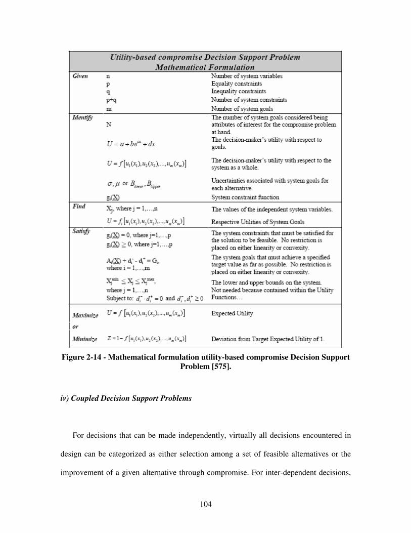
104
Figure 2-14 - Mathematical formulation utility-based compromise Decision Support
Problem [575].
iv) Coupled Decision Support Problems
For decisions that can be made independently, virtually all decisions encountered in
design can be categorized as either selection among a set of feasible alternatives or the
improvement of a given alternative through compromise. For inter-dependent decisions,
105
involving a bi-directional flow of information, or dependent decisions, involving a one-
way flow information, coupled DSPs are necessary. Coupled DSPs are hybrid constructs
that consist of any permutation of selection or compromise decisions. According to
Fernandez [202], in the case of selection/selection it is possible to encounter dependent
attributes, dependent alternatives or both; in the case of compromise/compromise it is
possible to encounter the constraints and goals being function of the variables of another;
and in the case of compromise/selection it is possible to encounter selection attributes
depending on compromise variables or compromise constraints and goals being functions
of selection variables. Furthermore, in the compromise/selection case it is possible that
different selection alternatives are tied to different math models for the associated
compromise DSP.
Since a selection DSP can be mathematically transformed into a compromise DSP, a
coupled DSP has the same mathematical form as a compromise DSP. In general, it can be
solved using the same procedure. However, if a selection DSP, which involves Boolean
variables, is transformed to instantiate a coupled DSP (or because selection alternative
ratings are not expressed as constants), a slightly modified solution procedure is required.
However, using the ALP algorithm incorporated in DSIDES, the solution to the
“reformulated” selection DSP which is a linear, 0-1 variable optimization problem can be
found without necessitating the use of specialized integer programming codes [45].
With care, the argument to guarantee Boolean behavior of continuous variables and
uniqueness can be extended to coupled multiple-selection problems. Bascaran and
coauthors [45] for example apply coupled DSP formulations to hierarchical selection in
engineering design. Here, the term hierarchical selection refers to selection problems that
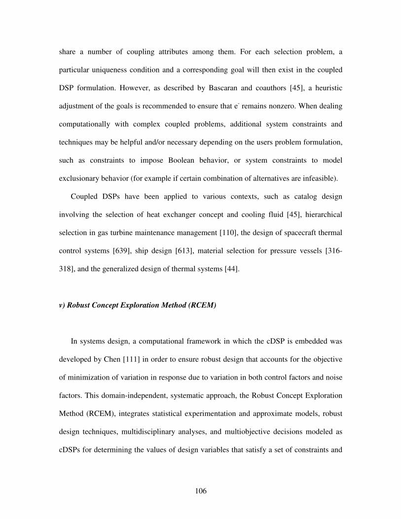
106
share a number of coupling attributes among them. For each selection problem, a
particular uniqueness condition and a corresponding goal will then exist in the coupled
DSP formulation. However, as described by Bascaran and coauthors [45], a heuristic
adjustment of the goals is recommended to ensure that e- remains nonzero. When dealing
computationally with complex coupled problems, additional system constraints and
techniques may be helpful and/or necessary depending on the users problem formulation,
such as constraints to impose Boolean behavior, or system constraints to model
exclusionary behavior (for example if certain combination of alternatives are infeasible).
Coupled DSPs have been applied to various contexts, such as catalog design
involving the selection of heat exchanger concept and cooling fluid [45], hierarchical
selection in gas turbine maintenance management [110], the design of spacecraft thermal
control systems [639], ship design [613], material selection for pressure vessels [316-
318], and the generalized design of thermal systems [44].
v) Robust Concept Exploration Method (RCEM)
In systems design, a computational framework in which the cDSP is embedded was
developed by Chen [111] in order to ensure robust design that accounts for the objective
of minimization of variation in response due to variation in both control factors and noise
factors. This domain-independent, systematic approach, the Robust Concept Exploration
Method (RCEM), integrates statistical experimentation and approximate models, robust
design techniques, multidisciplinary analyses, and multiobjective decisions modeled as
cDSPs for determining the values of design variables that satisfy a set of constraints and
107
balance a set of conflicting goals, including bringing the mean on target and minimizing
variation associated with each performance parameter. RCEM is employed successfully
for a simple structural problem and design of a solar powered irrigation system [111], a
High Speed Civil Transport [112], a General Aviation Aircraft [599], a turbofan turbine
propulsion system [328], product platforms [602], linear cellular alloys (Robust
Topological Preliminary Design Exploration Method (RTPDEM)) [577] and other
applications [120].
Furthermore, system design principles have also been incorporated in the basic
RCEM by Koch [328] to facilitate the design of complex, hierarchical systems (as further
discussed in the following section). Also, Choi [129] presented the RCEM-EMI approach
for robust design by incorporating Error Margin Indices within the basic RCEM to
address nuances of materials design in the face of various sources of uncertainty. The
RCEM-EMI approach is successfully employed for the design of multifunctional
structural materials a problem as complex as the design of four-phase exothermic powder
mixtures for reaction initiation under shock impact loading, robust against model
parameter uncertainty and microstructure variability [128].
Recent extensions that address nuances of materials design in the face of various
sources of uncertainty as proposed by Choi [128] as well as topology design of
multiphase microstructures as proposed by Seepersad [577], are well-suited since they
address the most common class of materials and product design problems: those for
which multifunctional performance requirements demand acceptable ranges of multiple
material and product properties dependent on phenomena in different physical domains
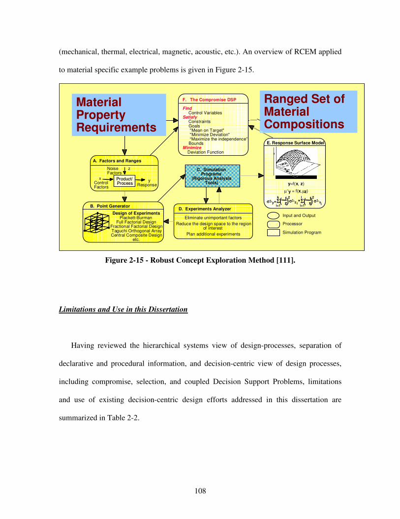
108
(mechanical, thermal, electrical, magnetic, acoustic, etc.). An overview of RCEM applied
to material specific example problems is given in Figure 2-15.
D. Experiments Analyzer
Eliminate unimportant factors
Reduce the design space to the regionof interest
Plan additional experiments
Robust, Top-Level Design Specifications
A. Factors and Ranges
Product/ Process
Noise z Factors
y Response
x Control Factors
F. The Compromise DSP
FindControl Variables
SatisfyConstraints Goals "Mean on Target" "Minimize Deviation" “Maximize the independence”Bounds
MinimizeDeviation Function
B. Point Generator
Design of Experiments Plackett-Burman
Full Factorial Design Fractional Factorial Design Taguchi Orthogonal Array Central Composite Design
etc.
E. Response Surface Model
y=f(x, z)
µˆy = f(x,µz)
σ2ˆy=Σi=1
k � f� zi
( )2σ2ˆz i
i=1
l � f� xi( )
2σ2ˆx
i+Σ
Input and Output
Processor
Simulation Program
C. SimulationPrograms
(Rigorous AnalysisTools)
Overall DesignRequirements
x1
x2
y
Ranged Set of Material Compositions
Material Property Requirements
D. Experiments Analyzer
Eliminate unimportant factors
Reduce the design space to the regionof interest
Plan additional experiments
Robust, Top-Level Design Specifications
A. Factors and Ranges
Product/ ProcessProduct/ Process
Noise z Factors
y Response
x Control Factors
F. The Compromise DSP
FindControl Variables
SatisfyConstraints Goals "Mean on Target" "Minimize Deviation" “Maximize the independence”Bounds
MinimizeDeviation Function
B. Point Generator
Design of Experiments Plackett-Burman
Full Factorial Design Fractional Factorial Design Taguchi Orthogonal Array Central Composite Design
etc.
E. Response Surface Model
y=f(x, z)
µˆy = f(x,µz)
σ2ˆy=Σi=1
k � f� zi
( )2σ2ˆz i
i=1
l � f� xi( )
2σ2ˆx
i+Σσ2ˆy=Σ
i=1
k � f� zi
( )2σ2ˆz i
i=1
l � f� xi( )
2σ2ˆx
i+Σ
Input and Output
Processor
Simulation Program
C. SimulationPrograms
(Rigorous AnalysisTools)
Overall DesignRequirements
x1
x2
y
x1
x2
y
Ranged Set of Material Compositions
Material Property Requirements
Ranged Set of Material Compositions
Material Property Requirements
Figure 2-15 - Robust Concept Exploration Method [111].
Limitations and Use in this Dissertation
Having reviewed the hierarchical systems view of design-processes, separation of
declarative and procedural information, and decision-centric view of design processes,
including compromise, selection, and coupled Decision Support Problems, limitations
and use of existing decision-centric design efforts addressed in this dissertation are
summarized in Table 2-2.
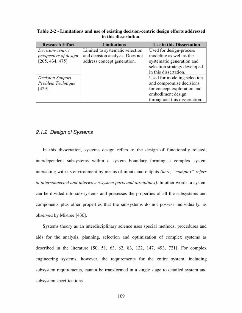
109
Table 2-2 - Limitations and use of existing decision-centric design efforts addressed
in this dissertation.
Research Effort Limitations Use in this Dissertation
Decision-centric
perspective of design
[205, 434, 475]
Used for design-process modeling as well as the systematic generation and selection strategy developed in this dissertation.
Decision Support
Problem Technique
[429]
Limited to systematic selection and decision analysis. Does not address concept generation.
Used for modeling selection and compromise decisions for concept exploration and embodiment design throughout this dissertation.
2.1.2 Design of Systems
In this dissertation, systems design refers to the design of functionally related,
interdependent subsystems within a system boundary forming a complex system
interacting with its environment by means of inputs and outputs (here, “complex” refers
to interconnected and interwoven system parts and disciplines). In other words, a system
can be divided into sub-systems and possesses the properties of all the subsystems and
components plus other properties that the subsystems do not possess individually, as
observed by Mistree [430].
Systems theory as an interdisciplinary science uses special methods, procedures and
aids for the analysis, planning, selection and optimization of complex systems as
described in the literature [50, 51, 63, 82, 83, 122, 147, 493, 721]. For complex
engineering systems, however, the requirements for the entire system, including
subsystem requirements, cannot be transformed in a single stage to detailed system and
subsystem specifications.
110
The traditional industrial approach for designing complex engineering systems by
simply transforming in multiple successive stages, termed requirements flowdown, or
even a more advanced requirements flowdown and feedback approach [328] break down
due to i) the number of variables and responses, ii) discipline expertise with
computational expense, and iii) multiple objectives with uncertainty. But, more
sophisticated optimization techniques have been developed to identify “optimal”
combinations more effectively and efficiently at each transformation level.
In each case iteration between levels of transformation detail is still necessary.
However, with the increase in computational capabilities and the development of
methodologies for composing component simulation models together to develop overall
system simulations, it is now progressively possible to evaluate the emergent behavior of
complete systems. These capabilities have elevated the role of simulation in design from
mere component failure analysis and parametric optimization to systems design and
given rise to the field of simulation-based design.
Designing complex engineering systems, design optimization is now a mainstream
discipline and a natural extension of the ever-increasing analytical capabilities of
computer-aided engineering. Supply-chain management and other business factors are
placing increased emphasis on a “systems” approach to product life cycle design.
Addressing the “system” problem, trends and challenges in system design optimization
have been reviewed by Paplambros and Michelena [485]. Also, Multidisciplinary Design
Optimization (MDO) is an expanding field that has many wide ranging applications in
system design optimization. Design problems having a number of disciplines that may
exhibit non-linear dependencies on each other can be difficult to deal with using
111
traditional optimization methods. Strategies such as sequential optimization are not able
to produce the true system optimum as they do not properly take into account the
discipline interactions. Only by considering these interactions during the optimization
process can the true optimum of a coupled system be determined.
The problem of size and discipline expertise usually precludes the integration of
system and multiple subsystem models into a single design problem. Hence, systems
must be partitioned or decomposed readily for distributed design. Since complex
engineering systems are not only composed of multiple subsystems, but are also
multidisciplinary in nature, the partitioning or decomposition of a system can thus follow
either the physical structure of the system (subsystem/component definitions) or the
disciplines involved in designing the system. These approaches (physical partitioning
versus discipline based decomposition) define informal (intuitive or heuristic) and formal
techniques respectively. Many studies have been devoted to the decomposition of large
systems and optimization problems, and many approaches for performing decomposition
exist; an excellent review of hierarchical decomposition is presented by Koch [328].
Informal, physical structure based, natural system partitioning approaches are
accepted over more formal approaches for mathematical decomposition in this
dissertation, simply because for most well-defined complex systems, the system
partitioning and links between system and subsystem levels are already defined. For more
complicated (less well-defined) complex systems, partitioning can be very difficult. But,
then, more formal decomposition techniques can be selected from the literature to aid in
partitioning the problem. However, dealing with complex engineering systems and
specialized materials design, the following characteristics cause simple optimization
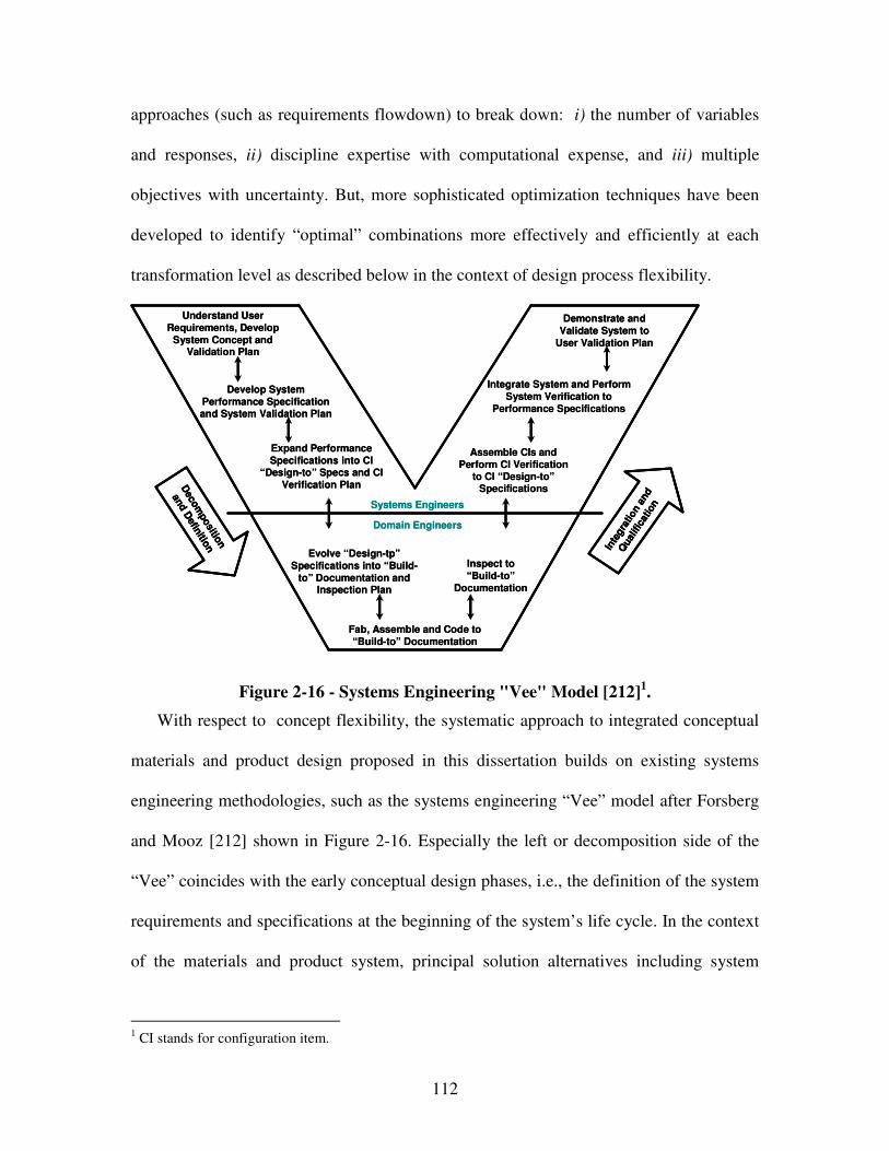
112
approaches (such as requirements flowdown) to break down: i) the number of variables
and responses, ii) discipline expertise with computational expense, and iii) multiple
objectives with uncertainty. But, more sophisticated optimization techniques have been
developed to identify “optimal” combinations more effectively and efficiently at each
transformation level as described below in the context of design process flexibility.
Understand User Requirements, Develop
System Concept and Validation Plan
Develop System Performance Specification and System Validation Plan
Expand Performance Specifications into CI
“Design-to” Specs and CI Verification Plan
Fab, Assemble and Code to “Build-to” Documentation
Evolve “Design-tp” Specifications into “Build-
to” Documentation and Inspection Plan
Inspect to “Build-to”
Documentation
Assemble CIs and Perform CI Verification
to CI “Design-to” Specifications
Integrate System and Perform System Verification to
Performance Specifications
Demonstrate and Validate System to
User Validation Plan
Inte
gra
tion a
nd
Qual
ific
atio
n
Deco
mpositio
n
and D
efinitio
n
Systems Engineers
Domain Engineers
Understand User Requirements, Develop
System Concept and Validation Plan
Develop System Performance Specification and System Validation Plan
Expand Performance Specifications into CI
“Design-to” Specs and CI Verification Plan
Fab, Assemble and Code to “Build-to” Documentation
Evolve “Design-tp” Specifications into “Build-
to” Documentation and Inspection Plan
Inspect to “Build-to”
Documentation
Assemble CIs and Perform CI Verification
to CI “Design-to” Specifications
Integrate System and Perform System Verification to
Performance Specifications
Demonstrate and Validate System to
User Validation Plan
Inte
gra
tion a
nd
Qual
ific
atio
n
Inte
gra
tion a
nd
Qual
ific
atio
n
Deco
mpositio
n
and D
efinitio
n
Deco
mpositio
n
and D
efinitio
n
Systems Engineers
Domain Engineers
Figure 2-16 - Systems Engineering "Vee" Model [212]1.
With respect to concept flexibility, the systematic approach to integrated conceptual
materials and product design proposed in this dissertation builds on existing systems
engineering methodologies, such as the systems engineering “Vee” model after Forsberg
and Mooz [212] shown in Figure 2-16. Especially the left or decomposition side of the
“Vee” coincides with the early conceptual design phases, i.e., the definition of the system
requirements and specifications at the beginning of the system’s life cycle. In the context
of the materials and product system, principal solution alternatives including system
1 CI stands for configuration item.
113
specification and material properties developed in the conceptual phase are handed off to
the domain engineers, such as material designers and scientists, as shown at the base of
the “Vee”. After individual physical components and multiscale models are developed,
responsibility then passes back to designers and system engineers, focusing on integration
and qualification of the product and material system.
In this dissertation, system and subsystems are modeled in terms of template-based
compromise Decision Support Problems (cDSPs) – domain-independent, modular,
reconfigurable, reusable, computer interpretable and archivable multiobjective decision
models as reviewed in detail in Section 2.1.2. Formulating subproblems as multiobjective
decisions in the form of template-based cDSPs, each subproblem may be solved by
expert designers using specialized analysis models. Systems designers however must
assign targets for coupled variables with most effect on system performance and allow
the expert designers to assign values to uncoupled parameters or coupled parameters that
have a relatively weak influence on system performance. However, systems designers do
not need to know all of the details of each of the expert designers solutions. But, they
must select the solution and associated design-process alternatives that achieve system
performance goals and requirements best. In the end, systems designers must solve the
most promising design process chain finding the solution that meets system-level
objectives best. Thus, the focus of systems design is on:
• generating concepts, during which the majority of costs is committed, as
illustrated in Figure 2-17,
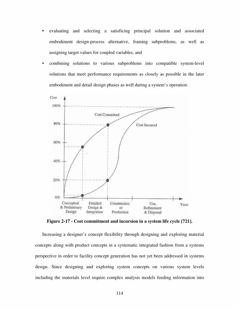
114
• evaluating and selecting a satisficing principal solution and associated
embodiment design-process alternative, framing subproblems, as well as
assigning target values for coupled variables, and
• combining solutions to various subproblems into compatible system-level
solutions that meet performance requirements as closely as possible in the later
embodiment and detail design phases as well during a system’s operation.
Figure 2-17 - Cost commitment and incursion in a system life cycle [721].
Increasing a designer’s concept flexibility through designing and exploring material
concepts along with product concepts in a systematic integrated fashion from a systems
perspective in order to facility concept generation has not yet been addressed in systems
design. Since designing and exploring system concepts on various system levels
including the materials level require complex analysis models feeding information into
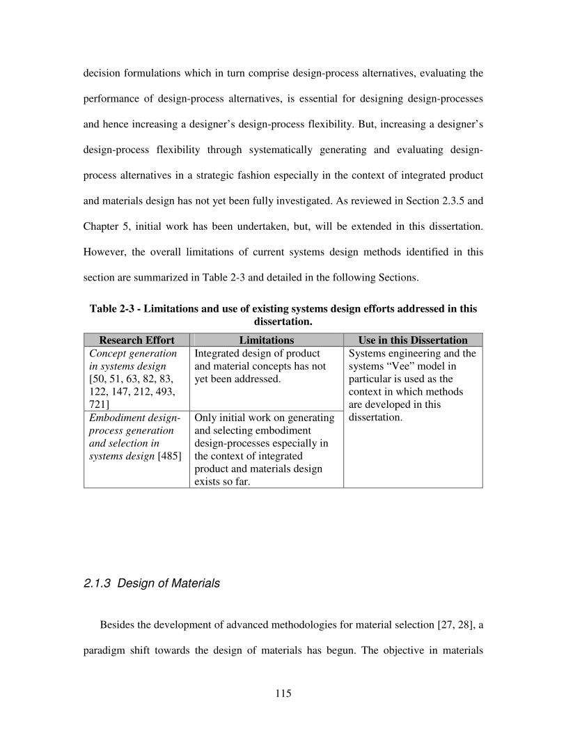
115
decision formulations which in turn comprise design-process alternatives, evaluating the
performance of design-process alternatives, is essential for designing design-processes
and hence increasing a designer’s design-process flexibility. But, increasing a designer’s
design-process flexibility through systematically generating and evaluating design-
process alternatives in a strategic fashion especially in the context of integrated product
and materials design has not yet been fully investigated. As reviewed in Section 2.3.5 and
Chapter 5, initial work has been undertaken, but, will be extended in this dissertation.
However, the overall limitations of current systems design methods identified in this
section are summarized in Table 2-3 and detailed in the following Sections.
Table 2-3 - Limitations and use of existing systems design efforts addressed in this
dissertation.
Research Effort Limitations Use in this Dissertation
Concept generation
in systems design
[50, 51, 63, 82, 83, 122, 147, 212, 493, 721]
Integrated design of product and material concepts has not yet been addressed.
Embodiment design-
process generation
and selection in
systems design [485]
Only initial work on generating and selecting embodiment design-processes especially in the context of integrated product and materials design exists so far.
Systems engineering and the systems “Vee” model in particular is used as the context in which methods are developed in this dissertation.
2.1.3 Design of Materials
Besides the development of advanced methodologies for material selection [27, 28], a
paradigm shift towards the design of materials has begun. The objective in materials
116
design is to tailor the chemical composition, constituent phases, microstructure and
processing paths to i) obtain materials with desired properties for particular applications
and thereby ii) satisfy multiple performance requirements on the system level, subject to
dynamic changes and constraints on certain materials properties such as density, strength,
conductivity, etc. [129, 413, 459, 475, 580, 581]. Most existing approaches for materials
design are focused on recently developed multiscale modeling techniques that allow
rapidly and accurately analyzing materials process-structure-property relationships [53,
129, 475]. So far, however, materials design is mostly leveraged in the embodiment and
detail design phase where resources to develop computational models of materials are
available. An overview of representative efforts related to materials design is provided in
Table 2-4 and discussed in the following.
Traditionally design engineers and materials scientists have adopted very different
approaches. Primarily, new materials have been developed with empirical, trial-and-error
techniques prominent in the natural sciences that cause length time frame and expense of
new materials development. With these techniques, a material is treated as a black box
subjected to repeated experiments. Experimental results then populate materials
databases. Since so far integration of design engineering and materials science in current
practice is still mostly limited to the selection of appropriate materials from the finite set
of available material databases, lead times for the development of new materials have
remained unacceptably expensive and long relative to product development cycles for
new products [413, 460]. Furthermore, even though the performance of many engineered
products and systems is limited fundamentally by the properties of available, constituent
materials, most product design methods are still based on the selection of an appropriate
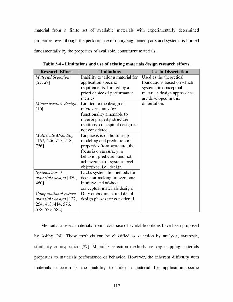
117
material from a finite set of available materials with experimentally determined
properties, even though the performance of many engineered parts and systems is limited
fundamentally by the properties of available, constituent materials.
Table 2-4 - Limitations and use of existing materials design research efforts.
Research Effort Limitations Use in Dissertation
Material Selection
[27, 28] Inability to tailor a material for application-specific requirements; limited by a priori choice of performance metrics.
Microstructure design
[10] Limited to the design of microstructures for functionality amenable to inverse property-structure relations; conceptual design is not considered.
Multiscale Modeling
[167, 426, 717, 718, 756]
Emphasis is on bottom-up modeling and prediction of properties from structure; the focus is on accuracy in behavior prediction and not achievement of system-level objectives, i.e., design.
Systems based
materials design [459, 460]
Lacks systematic methods for decision-making to overcome intuitive and ad-hoc conceptual materials design.
Computational robust
materials design [127, 254, 413, 414, 576, 578, 579, 582]
Only embodiment and detail design phases are considered.
Used as the theoretical foundations based on which systematic conceptual materials design approaches are developed in this dissertation.
Methods to select materials from a database of available options have been proposed
by Ashby [28]. These methods can be classified as selection by analysis, synthesis,
similarity or inspiration [27]. Materials selection methods are key mapping materials
properties to materials performance or behavior. However, the inherent difficulty with
materials selection is the inability to tailor a material for application-specific
118
requirements or novel system concepts. Necessary combinations of properties might
simply not be available from materials in current databases. Also, methods for conceptual
design are not applied to the “material” level. However, since successful design is so
closely linked with materials science, imagine the possibilities generated by
supplementing materials selection with materials design capabilities for synthesizing
customized materials with specific performance characteristics.
Koller clustered materials that exhibit various mechanical, thermal, electrical,
magnetical, aesthetic, optical, etc. properties in tables for selection [332]. Ashby on the
other hand focused clustering in graphical form – “bubble charts” which virtually
represent material groups and their properties [27, 28]. Also, Koller as well as Ashby
reviewed and summarized properties of a variety of metals, alloys, composites,
dispersions, ceramics, glasses, polymers – hence, they established a classification scheme
by broad designations of material types. Alternative classification schemes are by the
general composition or form, others by use, and still others by geometry.
In Table 2-4, it is noted that multiscale modeling of materials is simply an element or
tool that may be employed in materials design, but does not in itself comprise materials
design. Typically, multiscale modeling efforts include multiscale homogenization
approaches, artificial neural networks, etc., as reviewed in the literature [167, 426, 717,
718, 756]. In fact, concurrent multiscale modeling typically has distinct objectives of
predicting response of structures or devices with accuracy in applications rather than
facilitating tailoring of materials to satisfy macroscale performance requirements. As
argued by Eberhart and Clougherty [175], no matter how fast the computer, if it must
search for an optimum property using accurate analysis models of an infinite number of
119
materials, it will still require infinite time to perform the search. Hence, the viewpoint of
materials design as an automated search exercise is very limited. Also, scientific, mostly
complex multiscale models might not be necessary in many cases because the goal of
materials is not to accurately predict material properties but to satisfy performance
requirements.
Bottom-up analysis is not design. The key to materials design is an interplay of
multiscale modeling with human decision-making. Hence, materials design must begin
with a set of performance requirements that map to materials properties. Then, using
knowledge of structure-property relationships, it is advantageous to identify a finite set of
candidate material concepts that are likely to possess these properties. As pointed out by
Eberhart and Clougherty [175], this is most efficient when constructing structure-
property relations on the quantum scale and then study these materials experimentally,
thereby turning computational empiricism into true design. The focus in this work is to
identify and classify structure-property relations on multiple length scales to facility the
design of material concepts to be further investigated through systems-based embodiment
materials design, in line with Smith’s observation that structure is best considered as a
hierarchy, with each of its levels characterized by a different length scale [610]. Process-
structure relations refer more to materials development and hence are not further
considered.
In this context, systems based materials design is an emerging multidisciplinary field
in which both science-based tools and engineering systems design methods are utilized to
tailor material structures and processing paths to achieve targeted properties,
performance, and functionality for specific applications [413]. Therefore, multiscale
120
modeling techniques [756], integrating information generated by different simulation
models at different length scales in a consistent manner so that the overall system
behavior can be predicted from the individual constituent models [53], are utilized to
design materials at multiple scales achieving performance that was not possible before.
Conceptually, materials design offers the potential to build “bottom-up”, i.e., creating
materials and structures with no defects and with novel properties. Furthermore,
constructing “bottom-up” is imagined to allow for self-assembly, in which the random
(non-continuum) motion of atoms will result in their combination, or for self-replication,
in which growth occurs through exponential doubling.
Materials design depends on phenomena that operate at multiple levels and scales,
spanning from materials to system levels, from angstroms to meters and from
picoseconds to years. Hence, a hierarchy of models must be developed and applied to
specific levels as well as length and time scales, from quantum mechanics, to molecular
dynamics to continuum to reduced order, to component, to subsystem, to system models,
etc. Each model is used to inform the formulation of other models on higher levels or
scales that capture the collective behavior of lower level or scale subsystems. But it is
very difficult to formulate even a single model for macroscopic material properties that
unifies all of the length scales [413]. While developing physics-based models that
embody relevant process-structure-property relations on different scales for diverse
functions has its own challenges, the complexity and restricted domain of application of
these models limit their explicit integration across the length and time scales. Hence, it is
advantageous to link models rather than developing a single, rigidly connected model.
121
The objective of materials designers is to tailor the chemical composition, constituent
phases, microstructure, and processing to obtain materials with desired properties for
particular applications [410]. For example, Olson [459, 460] employs a systems approach
for designing advanced steels with multilevel microstructures on quantum, nano, and
micro length scales as illustrated in Figure 2-18. Materials design efforts rely on
continuous development and improvement of predictive models and simulations on a
various length scales, quantitative representations of structure, and effective archiving,
management, and visualization of materials-related information and data. Together, these
components provide important deductive links within a hierarchy of processing, structure,
properties, and performance. Such deductive, analytical tools are necessary but not
sufficient for materials design. As proposed by Olson [459], materials design is
fundamentally an inductive, goal-oriented, activity, aimed at identifying material
structures and processing paths that deliver required properties and satisfy performance
requirements, as illustrated in Figure 2-18. Hence, the materials design challenge is to
develop methods that employ bottom-up modeling and simulation, calibrated and
validated by characterization and measurement to the extent possible, yet permit top-
down exploration of the hierarchy of material scales [413].
The inductive or deductive mappings that are necessary to support materials design
according to Olson’s hierarchy shown in Figure 2-18 specifically involve [413]:
• process-structure relations that are used to establish manufacturing constraints,
cost factors, thermodynamic and kinetic feasibilities of process routes,
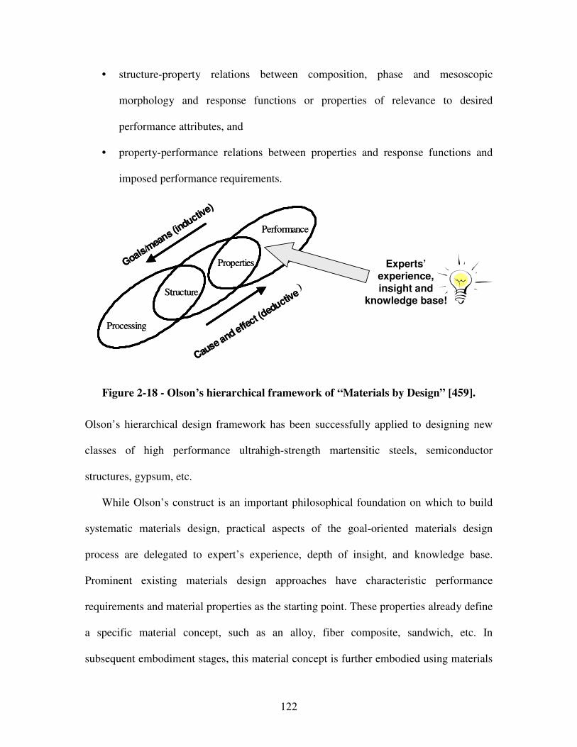
122
• structure-property relations between composition, phase and mesoscopic
morphology and response functions or properties of relevance to desired
performance attributes, and
• property-performance relations between properties and response functions and
imposed performance requirements.
Structure
Properties
Performance
Goals/mea
ns (inductiv
e)
Cause and effe
ct (deductiv
e)
Processing
Structure
Properties
Performance
Goals/mea
ns (inductiv
e)
Cause and effe
ct (deductiv
e)
Processing
Experts’experience, insight and
knowledge base!
Figure 2-18 - Olson’s hierarchical framework of “Materials by Design” [459].
Olson’s hierarchical design framework has been successfully applied to designing new
classes of high performance ultrahigh-strength martensitic steels, semiconductor
structures, gypsum, etc.
While Olson’s construct is an important philosophical foundation on which to build
systematic materials design, practical aspects of the goal-oriented materials design
process are delegated to expert’s experience, depth of insight, and knowledge base.
Prominent existing materials design approaches have characteristic performance
requirements and material properties as the starting point. These properties already define
a specific material concept, such as an alloy, fiber composite, sandwich, etc. In
subsequent embodiment stages, this material concept is further embodied using materials
123
design based on multiscale modeling efforts. Hence, focus is on extensive computational
model building on multiple scales to analyze behavior during the embodiment design
phase.
Aspects of how to get from performance requirements to a characteristic structure of
a specific material concept however have so far been delegated to experts’ experience,
depth of insight and knowledge base as illustrated in Figure 2-18. Materials design
approaches have focused so far on exploring one or two concepts based on expert
intuition. Typically, these few principal solution alternatives are then scientifically
analyzed and evaluated in the embodiment design phase to converge to a final design
solution. However, so far converging to the final design solution mostly involves finding
a single-point “optimum” focusing on fully coupled/integrated multiscale modeling
efforts.
Examples of systematic design methodologies that make embodiment materials
design less ad-hoc and intuitive while focusing on finding “satisficing” and robust
solutions include the decision based design philosophy proposed by Mistree and co-
authors [430] and the Robust Concept Exploration Method proposed by Chen [111, 112,
115], Seepersad [577, 582] and Choi [129, 131] and coauthors. Here, a material is viewed
as a hierarchical system in its own right, with nanostructure and microstructure defining
relation of structure to behavior at various length and time scales. This is required to
address nonlinear, hierarchical nature of materials based on high performance computing
and related simulation tools to provide a predictive foundation to support materials
design. However, these existing materials design approaches do not address the
124
conceptual design phase – the most crucial design stage in which decisions allocate the
vast majority of a product’s resources – in a systematic fashion.
Currently, the materials design community is focused on analysis – analysis meaning
the prediction of achieved behavior [229]. Systematic and domain-independent design
space exploration in the conceptual stage is however crucial. The early conceptual
abstraction and synthesis part of design, i.e., generating concepts with characteristic
properties of the structure based on given performance requirements or the expected
behavior that the system should have in order to satisfy the functional requirements, is
currently done in a more or less ad-hoc and intuitive fashion. However, exhaustive
problem analysis must precede solution synthesis. But, synthesis in its general sense, i.e.,
the combining or mixing of ideas or things into new ideas or things, is currently not
addressed methodically in materials design.
In design, synthesis, or in other words the association of elements to form a whole
involving search and discovery as well as combination and composition [469], is crucial.
In combination with abstraction, it is an integral part of every design process, especially
in the early stages when designers focus on generating and selecting concept and thereby
unrecoverably allocating most resources for the rest of the product life cycle. However,
only relying on a designer’s or design team’s personal experiences during concept
generation may result in the exclusion of a vast array of feasible concepts [374]. Also, as
argued by Eberhart and Clougherty, synthesizing quantum scale structure-property
relationships is key to materials design. Therefore, a function-based approach for
integrated design of material and product concepts is developed in this dissertation in
order to i) render conceptual design of materials, i.e., generation of feasible concepts,
125
more systematic, i.e., less dependent on experts’ experience, insight and intuition as
illustrated in Figure 2-18, and ii) increase a designer’s flexibility, as described in the
following sections.
2.1.4 Flexibility in Design
According to Fitzgerald and Siddiqui [209] “change is endemic and the environment
is increasingly turbulent”. Due to the nature of dynamic demands, competitive markets,
rapid technological change, political climates, and the environment’s limited resources,
flexibility is crucial to achieve continuous improvement in the design of existing complex
engineering systems. In this context, the value of flexibility has been captured by
Trigeorgis [671]: “Flexibility has value. While this statement is obvious at the conceptual
level, it is surprisingly subtle at the applied level. Professional managers have long
intuited that [flexibility is an important element] in valuation and planning decisions.”
According to Nilchiani and Hastings [453], design flexibility is required in case of:
i) variability of demand (random or seasonal),
ii) short life-cycles of the products and technologies,
iii) wide range of product families,
iv) increased customization, and
v) short delivery times.
As noted by Saleh and coauthors [560], flexibility has become in recent years a key
concept in many fields, particularly in most design endeavors. According to Webster
126
[715], being flexible in general refers to being “willing or ready to yield to the influence
of others, not invincibly rigid or obstinate, tractable, manageable, …”. Definitions of
flexibility and associated concept, design-process, and product flexibility are summarized
in Figure 1-3 and described in greater detail in the following.
In management, for example, flexibility refers to the ability to affect the course of a
project by acting in response to the resolution of market uncertainty over time [560]. In
other words, flexibility refers to the capability to adapt to changing conditions that helps
ensure continuity of the organization [209]. Since today’s market requires that important
investment decisions be made in very uncertain environments, the concept of flexibility is
hailed as critical for management and operations research, as for example introduced in
the context of Decision Tree Analysis [760] and Real Options Management [671].
In manufacturing systems, different types of flexibility are defined based on the
nature of change the production system can accommodate. Prominent concepts in this
literature are volume flexibility, product mix flexibility, routing flexibility, operations
flexibility, as for example defined by Fitzgerald and Siddiqui [209]. According to Fricke
and coauthors [216] a differentiation is made between agility as the “property of a system
to implement changes rapidly” and flexibility as the “property of a system to be changed
easily and without undesired effects” in this context. However, review of manufacturing
flexibility and reconfigurable manufacturing systems can be found in the literature [18,
48, 151, 337, 418, 585, 768].
In design, flexibility has become a necessity before and after the characteristic time
when a system is fielded, i.e., is in operation. In this dissertation, concept and design-
process flexibility refer to a designer’s flexibility before the time when a system is fielded
127
(particularly in response to known and unknown dynamic demands, concurrent design
and distributed environments), whereas product flexibility refers to a designer’s
flexibility after this characteristic time (particularly in response to changing customer
needs and changes that occur in a system’s environment (e.g., political, cultural,
organization, etc.) or in the system itself (e.g., wear and tear over time)). In this
dissertation, product flexibility maps to the ability to realize open engineering systems,
described by Simpson, Lautenschlager and Mistree as “systems of industrial products,
services and/or processes that are readily adaptable to changes in their environment
which enable producers to remain competitive in a global marketplace through
continuous improvement and indefinite growth of an existing technology base” [597].
As motivated in Section 1.1, increasing a designer’s flexibility in identifying, framing
and evaluating system concepts (concept flexibility), associated complex design-
processes (design-process flexibility), as well as system architectures (product
flexibility), as described and defined in the following sections, becomes crucial. Having
reviewed the concept of flexibility in different fields, its value and classification in this
dissertation, formal definitions become necessary.
According to Webster [715], being flexible in general refers to being “willing or ready
to yield to the influence of others, not invincibly rigid or obstinate, tractable, manageable,
…”. Intuitively, flexibility is understood as the ability to respond to change. Fricke and
coauthors elaborate this intuitive meaning of flexibility and add that flexibility is a
property characterizing a system’s ability to be changed easily [216, 217]. However,
these definitions fail to distinguish flexibility clearly from other properties such as
robustness, adaptability, changeability, agility, etc. Since, flexibility is a word rich with
128
ambiguity, efforts were undertaken by Saleh and coauthors [560] to synthesize a formal
definition of flexibility in systems design. The key to their definition is that flexibility
implies the ability of a system to satisfy changing requirements.
In contrast to flexibility, robustness involves satisfying a fixed set of requirements
despite changes in the system’s environment or within the system itself. In other words,
robustness has to be built-in into a system, whereas flexibility has to be embedded in a
system; meaning, new system capabilities can be created in response to changes in initial
system requirements and objectives in an effective and efficient way during the design
process or after a system has been fielded, i.e., in its operation.
Based on a temporal scale, as defined by Zelenovich [762], flexibility in this
dissertation refers more to medium and long-term temporal scales, which are typically
related to design adequacy. Adaptability on the other hand refers to short-term temporal
scales. However, as defined by Olewinik and coauthors [458], the key difference between
adaptability and robustness is that a system is robust to unpredictable changes in the
operating environment whereas a system can only be adaptable to predictable changes in
the operating environment. Also, flexibility is not to be confused with universality. In
contrast to flexible systems, universal systems can be used in a variety of situations
without change or modification.
Consequently, in this dissertation, the flexibility, concept flexibility, design-process
flexibility, and product flexibility are defined as follows:
Flexibility is the ability to respond to known or unknown dynamic changes in
performance requirements with ease.
129
Concept flexibility in the conceptual and early embodiment design phases is the ability to
generate and select concepts, map their respective performance spaces as well as frame
subproblems to allow response to dynamic demands at different points in a product’s life
cycle with ease.
Design-process flexibility in the later embodiment and detail design phases is the ability
to “mitigate the risks – cost, schedule and performance – resulting from requirement
changes occurring during the design process, i.e., before fielding a system” with ease
[560].
Product flexibility is the ability to realize open engineering systems and “respond to
changes in [the system’s] initial objectives and requirements – both in terms of
capabilities and attributes – occurring after the system has been fielded, i.e., is in
operation, with ease in a timely and cost-effective way” with ease [560].
Hence, in design, concept, design-process and product flexibility are crucial to increase a
designer’s flexibility at different points in time.
Indicators of a designer’s flexibility – in other words concept, design process and
product flexibility respective –are:
i) concept performance ranges, concept functionality, concept realizability, ease of
concept generation, concept variety, concept quantity and concept novelty of
principal solutions satisfying known or unknown dynamic demands from a
systems perspective,

130
ii) speed and quality of information gathering used for decision making in complex
design processes, as well as
iii) time and cost required to implement changes in system architectures.
A more detailed overview of product flexibility measures is for example given by Keese
and coauthors [320]. However, the focus in this dissertation is on increasing a designer’s
concept and design-process flexibility. Concept flexibility indicators are reviewed in
detail in Chapter 4. Design-processes are evaluated based on a value-of-information-
based concept, described in detail in Section 2.4 and Chapter 5. However, methods and
tools to increase a designer’s product flexibility are reviewed in order to show how they
can be used within the systematic approach to increase a designer’s concept and design-
process flexibility developed in this dissertation.
Activities, methods and tools for increasing a system designer’s flexibility in
identifying, framing and evaluating system concepts (concept flexibility), associated
mulsticale design processes (design process flexibility), as well as well as system
architectures (product flexibility), are presented and described in greater detail in the
following sections.
131
2.2 Methods and Tools to Achieve Concept Flexibility
A prominent area of research addressing a designer’s flexibility in the conceptual and
early embodiment design phases is focused on concept flexibility – in this dissertation
defined as the ability to generate and select concepts, map their respective performance
spaces as well as frame subproblems to allow response to dynamic demands at different
points in a product’s life cycle with ease. The value of flexibility is obvious at the
conceptual level. During the conceptual phase, the most crucial design stage in which
decisions allocate the vast majority of a product’s resources, system designers
collaborating with expert designers need the flexibility to identify, frame and select the
most promising solutions that balance system-level objectives depending on known or
unknown dynamic demands. As has been shown in the car industry, applying set-based
concurrent engineering and thereby emphasizing conceptual design efforts makes finding
the best or better solutions more likely while keeping faster development cycles [616].
It is crucial to maintain concept flexibility, in other words being able to foster a
number of concepts in response to known or unknown dynamic demands at the same time,
as close to market introduction as possible when making conceptual design decisions. At
the heart of concept flexibility is the ability to generate many concepts to realize
functional relationships. It has often been said that working with a single concept is a
recipe for disaster [516, 679]. Various approaches to achieve concept flexibility are
reviewed in the following, such as function-based systematic design [470], general
solution finding methods, set-based design [616], and design axioms [20, 522, 642].
132
2.2.1 Systematic Function-Based Conceptual Design
It is difficult to determine the real origins of systematic design. Looking at the use of
systematic variation of possible solutions, some authors trace it back to early master such
as Pythagoras, Sokrates, Archimedes or Leonardo da Vinci [462, 469], but, missing
documentation prohibits a thorough analysis. In general though, up to the industrial era,
designing was closely associated with arts and crafts. With the rise of mechanization then,
principles of systematic design were increasingly developed and documented for
widespread use. The historical background and current methods of systematic design
methodologies are reviewed and summarized by Pahl and Beitz [469]. However,
Redtenbacher and Reuleaux pioneered some of the earliest ideas on the principles of
systematic design in the 1850s. The first step-by-step approach was developed Erkens in
the 1920s. The concept of systematic design was stimulated in the 1950s and 1960s by
Kesselring, Tschochner, Niemann, Matousek and Leyer – identifying the various phases
and steps of the design process, and providing specific recommendations and guidelines
for tackling them [699].
It is not possible to mention every researcher, but key contributions to systematic
design were made by Hansen [249], Rodenacker [547], Roth [552], Koller [332],
Erhenspiel [179] and Pahl and Beitz [699]. In an attempt to unify the diversity of existing
function-based systematic design approaches and perspectives – such as the ones by Roth
[552], Rodenacker [547], Koller [332] or Pahl and Beitz [470] – a generic approach to the
function-based systematic design of technical systems and products, emphasizing the
133
general applicability in the fields of mechanical, precision, control, software and process
engineering, has been proposed by an “Association of German Engineers” committee
(VDI guidelines 2221 and 2222).
However, systematic conceptual design has traditionally been linked to representing
designs and engineering systems in terms of the functions they must fulfill. Functional
relationships are usually combined in terms of energy, matter and information flows and
enclosed by (sub-)system boundaries. One of the most well known function-based
systematic design methodologies however is the one proposed by Pahl and Beitz for the
mechanical engineering domain [469]. Pahl and Beitz propose a function-based
systematic planning and design process for mechanical engineering (with reference to
VDI Guidelines 2221 and 2222), based on best practices from industry [469]. Pahl and
Beitz divide the planning and design process into four main phases and propose main
working steps for each of these phases, as described in great detail in Chapter 3 for the
conceptual design phase.
It has been shown that a systematic design methodology, involving strategically and
tactically ordered successive steps of information transformations, supports designers to
solve problems more efficiently and effectively than others [469], especially during
conceptual design. Any systematic design method consists of one or several of the
following general methods: analysis, abstraction, synthesis, method of persistent
questions, method of negation, method of forward steps, methods of backward steps,
method of factorization, method of systematic variation, division of labor and
collaboration. From these general methods, functional decomposition, analysis,
abstraction, synthesis and systematic variation are leveraged as core transformations for
134
the function-based systematic approach presented to design product and material
concepts in an integrated fashion in this dissertation.
Function-based systematic design methodologies so far are based on conceptual
product design followed by material selection in the embodiment design phase. Material
selection in the embodiment design phase limits designers in that the potential embedded
in materials design is not leveraged in the early stages of design. Conceptual design focus
has so far been on design of various types of connections, guides and bearings, power
generation and transmission, kinematics and mechanisms, gearboxes, safety technology,
ergonomics, as well as production processes. However, cconsidering phenomena and
associated solution principles on multiple levels and scales from the materials domain
when satisfying functional system requirements in the conceptual design phase, designers
may overcome restrictions to product creation imposed by materials selection.
Also, systematic determination of system concepts that can be characterized by
specific properties based on performance requirements, has not yet been exploited in
materials design. As described in Chapter 3, developing multilevel function structures,
including the materials level, through functional analysis, abstraction and synthesis
increases a designer’s concept flexibility. Also, it supports clear definition of the
interfaces in the integrated product and material system. This permits the definition of
independent subproblems and their allocation to the individual disciplines and domain
engineers involved. Within a function-based systematic approach, solutions can be
systematically elaborated using several existing solution finding methods and tools, as
reviewed in the following.
135
2.2.2 Solution Finding Methods
Several solution finding methods have been proposed in the engineering,
management, and education literature. Current state of the art methods are reviewed in
the following. These methods are classified in:
• conventional methods (information gathering, analysis, synthesis, analogies,
measurements, and model tests),
• intuitive methods (intuition, ideation cards, abstraction, brainstorming (method
635, gallery method), input/output technique, synectics (Gordon technique),
lateral thinking, visual thinking, attribute listing, forced relationship technique,
blockbusting, delphi method, and parameter analysis),
• discursive methods (method of persistent questions, checklisting, morphological
thinking, method of negation (systematic doubting), method of forward steps
(method of divergent thought), method of backward steps (method of convergent
thought), method of factorization, method of systematic variation, systematic
study of physical processes, systematic search with the help of classification
schemes or design catalogs), and
• methods for combining solutions (systematic combination, combining with the
help of mathematical methods).
136
Conventional Methods
Information Gathering
Information can be gathered from textbooks and technical publications, patent files,
diverse websites and brochures published by competitors. A variety of tools are
available for searching the many worldwide patent databases. Among these tools are
the European Patent Office website (http://ep.espacenet.com), the United States
Patent and Trademark Office website (http://www.uspto.com), and the Free Patents
Online website (http://www.freepatentsonline.com). A number of software packages
also exist for searching the various patent databases and providing an aid in
understanding the complex relationships between patents. These include IPVisions,
Aureka and PatentWeb, Public Web Examiner Search Tool. Literature search
provides a most useful survey of known solution possibilities. Increasingly, this type
of information is fed into computer databases and stored for future use.
Real solutions can be found within the own or the competitor company, which may
be altered through systematic variation. Furthermore, real solutions are found on the
supplier market, in property rights, virtual marketplaces or virtual supply chains.
Analysis
Analysis is the resolution of anything complex into its elements and the study of these
elements and of their interrelationships. It calls forth identification, definition,
structuring and arrangement [470]. It calls for identification, definition, structuring
and arrangement through which the acquired information is transformed into
137
knowledge. Analysis is the prediction of achieved behavior, i.e., a set of physical
properties achieved by the proposed design solution, from the structure which
represents the artifact’s physical form [229].
Synthesis
Synthesis is the association of elements to form a whole involving search and
discovery as well as combination and composition [470]. Synthesis involves coming
up with the structure based on the expected behavior, i.e., in our context, the physical
properties that the artifact should have, in order to satisfy the given requirements and
performance goals based on the expected behavior described through idealized
functional relationships.
Analogies
In the search for solutions and in the analysis of system properties, it is often useful to
substitute an analogous problem or system for the one under consideration, and to
treat it as a model [470]. For example, representing analogies to increase the
probability of innovation has been investigated by Linsey and coauthors [374].
Analysis of natural systems for example can lead to very useful and novel technical
solutions, stimulating creativity of designers. Currently, the connections between
biology and technology are investigated in great detail by bionics and biomechanics.
Also, analysis of existing artificial (man-made) systems, products or processes is one
of the most important means of generating new or improved solution variants in a
step-by-step manner. It may involve the mental or even physical dissection of
138
finished products and is aimed at the discovery of related logical, physical and
embodiment design features.
Measurements and Model Tests
Measurements on existing systems, model tests supported by similarity analysis and
other experimental studies are among the most important sources of information in
design [470].
Intuitive Methods
Intuitive solutions suddenly appear as conscious thoughts and often their origins
cannot be traced. Initial intuitive solutions are usually developed, modified and amended,
until such time as it leads to the most promising solution of the problem.
Intuition
Intuition has led to a large number of good and even excellent solutions. But, the right
idea rarely comes at the right moment, cannot be elicited nor elaborated and strongly
depends on individual talent and experience. The prerequisite is a very conscious and
intensive involvement with the given problem.
Ideation Cards
Ideas are documented on special cards and filed for future use.
139
Abstraction
Through abstraction, complexity is reduced and essential problem characteristics are
emphasized so that coincidental solution paths may be avoided and more generic
(non-intuitive) solutions may be found [470]. In other words, compared to an intuitive
and ad-hoc solution finding process, designers may find better solutions containing
the identified characteristics through abstraction.
Brainstorming
Brainstorming, initially proposed by Osborn [463], is a systematic, group-oriented
technique for deliberately producing and developing a large number of ideas. In
brainstorming, the quantity as opposed to the quality of ideas is emphasized.
Important Brainstorming Spin-offs are the Method 635 (form group of about six;
identify ideation task; participants write down three solution keywords; keywords are
passed to neighbor, who records three further solutions or developments; ideas are
passed again, a total of five times), the gallery method (form a group; identify
ideation task; individuals sketch solutions for 15 minutes; group review sketches for
15 minutes; individuals further develop and refine ideas; group finalizes ideas and
selects promising ones) and collaborative sketching (in which designers work on
developing graphical representations of solutions to a design problem).
140
Input/Output Technique
The input/output technique [365] is the foundation for functional analysis, a staple of
Value Engineering. After abstracting the essential elements (e.g. components, tasks,
processes, …), the input and output flows that logically connect such elements are
identified.
Synectics (Gordon Technique)
Synectics, as proposed by Gordon [238], is an operational theory of creativity. Two
guiding principles, “making the familiar strange” and “making the strange familiar”,
are respectively implemented through analogy and metaphorical analysis. In essence,
Synectics is comparable to Brainstorming with the difference that its aim is to trigger
off fruitful ideas with the help of analogies form nontechnical or semi-technical fields.
Lateral Thinking
Lateral Thinking, coined by DeBono [153], is founded on the principle that changing
established information patterns generates creative ideas. It is implemented with a
variety of tools, including “Plus-Minus-Interesting”, “Six Thinking Hats”, or random
stimuli. These tools force individuals to change their limited, rigid perceptions and
restructure information patterns anew.
Visual Thinking
The significant role of imagery in human thinking processes is emphasized by Visual
Thinking as proposed by McKim [417]. It is carried out by interactions among
141
perceiving visual stimuli, dreaming up visual images and sketching, doodling,
painting, … . The interplay among such imagery provides a powerful technique for
thinking.
Attribute Listing
Attribute-Listing, developed by Crawford [144], is a creative technique involving the
attributes, i.e. descriptive qualities or characteristics, of concepts. Novel ideas are
generated by altering attributes through modification, substitution and application
elsewhere.
Forced Relationship Technique
Forcing relationships between normally unrelated things and ideas is the prescription
for creativity in the so-called Forced Relationship Techniques [644]. By
superimposing two or more different ideas that have no apparent connection, new and
original associations can be generated.
Blockbusting
“Blockbusting” adopts a completely different approach to creativity, namely breaking
habits and removing barriers that inhibit creative thinking. Conceptual blocks are
“mental walls that block the problem-solver from correctly perceiving a problem or
conceiving its solution” [11]. Such blocks are of the following types: perceptual,
cultural, emotional, intellectual, cultural, expressive and environmental.
142
Delphi Method
In the Delphi method, as proposed by Dalkey and Helmer [150], experts in a
particular field are asked for written opinions. The elaborate procedure consists of
many rounds and must be planned very carefully. It is usually confined to general
problems bearing on fundamental questions or on company policy. In the field of
engineering design, the Delphi method should be reserved for fundamental studies of
long-term developments.
Parameter Analysis
Parameter analysis [370] involves analyzing variables to determine their relative
importance. The most important variables become the focus of the investigation, with
other variables being set aside. After the primary issues have been identified, the
relationships between the parameters that describe the underlying issues are examines.
Through an evaluation of the parameters and relationships, one or more solutions are
developed.
Combination of Methods
Any one of these methods taken by itself may not lead to the required goal. The
different methods should be combined so as best to meet particular cases. A
pragmatic approach ensures the best results.
143
Discursive Methods
Discursive methods are procedures that tackle problems step by step. Steps are
chosen intentionally, can be influenced and communicated. A problem is rarely tackled as
a whole, but is first divided into manageable parts and then analyzed. Individual ideas or
solution attempts are consciously analyzed, varied and combined. Discursive methods do
not exclude intuition, which can make its influence felt during individual steps and in the
solution of individual problems, but not in the direct implementation of the overall tasks.
The additional use of systematic procedures can only serve to increase the output and
inventiveness of talented designers. Any logical and systematic approach, however
exacting, involves a measure of intuition that is an inkling of the overall solution. No real
success is likely without intuition.
The Method of Persistent Questions
The basic idea is to ask questions as a stimulus to fresh thought and intuition. A
standard list of questions also fosters the discursive method [470].
Checklisting
Checklisting [228] is a method by which creative thought is stimulated by a pre-
existing list of suggestions or alternatives. Catalogs of existing ideas and entities
serve as a comprehensive form of checklist.
144
Morphological Thinking
Morphological thinking is “the study of the totality of all possibilities inherent in any
set of circumstances” [773]. This systematic approach to creative discovery is
achieved by enumerating all parameters characterizing a subject and combining the
parameters in new and different ways. This is facilitated through the use of a
morphological matrix.
The Method of Negation (Systematic Doubting)
The method of deliberate negation starts from a known solution, splits it into
individual parts or describes it by individual statements and negates these statements
one by one or in groups [470].
The Method of Forward Steps (Method of Divergent Thought)
Starting from a first solution attempt, one follows as many paths as possible yielding
further solutions. This method is not necessarily systematic. It frequently starts with
an unsystematic divergence of ideas [470].
The Method of Backward Steps (Method of Convergent Thought)
The starting point for this method is the goal rather than the initial problem.
Beginning with the final objectives of the development, one retraces all the possible
paths that may have led up to it. Only such ideas are developed as converge on the
ultimate goal [470].
145
The Method of Factorization
Factorization involves breaking down a complex interrelationship or system into
manageable, less complex and more easily definable individual elements (factors)
[470]. The overall problem is divided into separate sub-problems that are to a certain
degree independent. Each of these sub-problems can initially be solved on its own,
though the links between them in the overall structure must be kept in mind.
The Method of Systematic Variation
Once the required characteristics of the solution are known, it is possible, by
systematic variation, to develop a more or less complete solution field [470]. This
involves the construction of a generalized classification, i.e., a schematic
representation of the various characteristics and possible solutions.
Systematic Study of Physical Processes
If the solution of a problem involves a known physical effect, and especially when
several physical variables are involved, various solutions can be derived from the
analysis of their interrelationships – that is, of the relationship between a dependent
and an independent variable, all other quantities being kept constant [470].
Systematic Search with the Help of Classification Schemes
Systematic presentation of data is beneficial because i) it stimulates the search for
further solutions in various directions, and ii) it facilitates the identification and
combination of essential solutions characteristics [470]. The usual two dimensional
146
classification scheme consists of rows and columns of parameters used as classifying
criteria. The choice of classifying criteria or of their parameters is of crucial
importance. Solution proposals are entered in the rows in random order. These
proposals are analyzed in the light of the headings (characteristics) and classified in
accordance with these headings.
This procedure not only helps with the identification of compatible combinations, but
more importantly, encourages the opening up of the widest possible solution fields.
Classifying criteria and characteristics can be useful when searching systematically
for solutions and varying solution ideas for technical systems.
Use of Design Catalogs
Design catalogues are collections of classified known and proven solutions to design
problems and contain data of various types and solutions of distinct levels of
embodiment [470, 552]. They should provide quicker, more problem-oriented access
to solutions.
Methods for Combining Solutions
It is often useful to divide problems and functions into sub-problems and sub-
functions and to solve these individually (factorization method). Once the solutions for
sub-problems or sub-functions are available, they have to be combined in order to arrive
at an overall solution. Problematic though is the selection of technically and

147
economically favorable combinations of principles from the large field of theoretically
possible combinations.
Systematic Combination
For the purpose of systematic combination, classification schemes or “morphological
matrixes” [773], where sub-functions and associated solution principles are entered in
the rows of the scheme, are particularly useful. For solution finding, solution
principles are combined systematically into an overall solution [470]. Problematic
with this method of combination is to decide which solution principles are
compatible, that is, to narrow down the theoretically possible search field to the
practically possible search field.
Combining With the Help of Mathematical Methods
In principle, the combination of subsolutions into an overall solution with the help of
mathematical methods depends on the knowledge of the characteristics or properties
of the subsolutions that are expected to correspond with the relevant properties of the
neighboring subsolutions [470]. These properties must be unambiguous and
quantifiable. Hence, this method should only be used in the later stages of design if
real advantages can be expected.
148
2.2.3 Set-Based Design
Set-based design is generally understood as abstract reasoning about sets of design
alternatives. As has been shown by applying set-based concurrent engineering in the car
industry, an approach including:
i) starting by broadly considering sets of possible solutions,
ii) communicating and reasoning about these sets of alternatives in parallel and
relatively independently,
iii) developing a sophisticated understanding of the boundaries on the solution
space, and only then
iv) gradually narrowing the set of possibilities as the design progresses by
eliminating inferior alternatives based on additional information,
makes finding the best or better solutions more likely while keeping faster development
cycles (making more sound decisions resulting in much less time “tweaking” the design)
[616]. Hence, it is crucial to maintain concept flexibility, in other words being able to
foster a number of principal solutions in response to known or unknown dynamic
demands at the same time, mapping the design space by defining feasible regions in order
to break free of cognitive constraints and converging to a final solution or set of solutions
as close to market introduction as possible when making crucial design decisions. In
terms of set-based design philosophies [371, 616, 710, 711], advantages of enhanced
concept flexibility are:
• multiple concepts are kept alive in each subproblem to accommodate dynamic
demands and changes in other parts of the multilevel and multiscale system,
149
• communication in terms of performance targets and ranges facilitates problem
directed and solution neutral collaboration in a distributed environment,
• subsystem designers are kept consistently in the loop, utilizing their expertise
without requiring automated computer simulations, and
• system designers may choose a satisficing solution from a variety of concepts to
satisfy known or unknown dynamic demands at any point in time.
Set Based Concurrent Engineering is based on the assumption that reasoning and
communicating about set of ideas is preferable to working with one idea at a time. One
solutions at a time results in iterations and is likely to involve much waste. Working with
sets simultaneously, the respective sets of solutions are narrowed gradually as the design
progresses based on additional information from development, testing, customers and
other participants sets. As the sets of solutions are narrowed, engineers commit to stay
within the sets so that others can rely on their communication. The key is to properly
manage and communicate design freedom by increasing knowledge.
Set Based Concurrent Engineering is based on the following principles [616]:
• Definition of feasible regions:
The problem is broken up into manageable chunks. Each function simultaneously
defines feasible ranges from its perspective. On past experience, key constraints
are based on the subsystem. From function’s perspective, critical features,
demands/wishes and performance levels are determined using knowledge from
current designs, experimentation, engineering analysis and experience.
150
• Communication of sets of possibilities:
The communication of sets of possibilities enables functions to understand
feasible regions of others. Sets of alternatives can be discrete options or bounded
intervals for parameters. Additional knowledge can be passed as tradeoff curves,
performance charts, simple tests, engineering checklists, etc.
• Looking for intersections of feasible sets:
Overlaps between feasible regions are identified. An intersection is a solution
acceptable to all. Main goal is to maximize overall system performance rather
than marrying independently optimized components.
• Exploring tradeoffs by designing multiple alternatives:
Trough designing, prototyping and simulating alternative subsystems, it can
intelligently be decided among alternatives. Whenever possible, relationships
should be established mathematically or test data should be gathered from a
number of test pieces.
• Imposing minimum constraints:
Making decisions early in the design process in order to simplify the subsystem
interactions imposes additional constraints. Minimization of constraints helps in
maintaining flexibility.
• Narrowing sets smoothly, balancing the need to learn and need to decide:
The decision process in Set Based Concurrent Engineering involves gradual
elimination of possibilities until the final solution remains rather than just picking
the best from a set. The key issue is to decide when to decide.
151
• Pursuing high-risk and conservative options in parallel:
If the new solution does not work by a certain date, resort to the conservative
solution.
• Establishing feasibility before commitment
• Staying within sets once committed
• Control by managing uncertainty at process gates:
The process is managed through a series of gates, each of which is tied to an
integrating even that brings all pieces together.
• Seek solutions robust to physical, market and design variation
Set Based Concurrent Engineering is used to maintain design freedom as long as
possible in the design process. Design freedom is defined as the extent to which a system
can be adjusted while still meeting its design requirements. If an upstream team presents
a ranged set of solutions in which any specific point in the range meets the design
requirements in its discipline, downstream teams specify (or shrink) the ranged solutions
based on the new design requirements and constraints of their disciplines, without
jeopardizing the final solution’s feasibility in the upstream discipline. However, a key
limitation of set-based design is that it is focused on the elimination of solutions from
solution sets. It is not a comprehensive approach and does not provide means for
systematic selection or concept generation.
Set-based design philosophies have been used for catalog design methods, for
example in the work of Ward and Seering [708, 709] or Bradely and Agogino [74]. These
methods use mathematical representations of the design problem and consider the search
for solutions as an identification of the feasible subset of design that satisfy a functional
152
specification [728]. However, a review of means for systematic selection for set-based
design can be found in the literature [388]. Current research is directed towards
systematic selection using multi-attribute utility analysis [386] and parameterized Pareto
sets to model design concepts [388].
2.2.4 Design Principles
In this dissertation, design principles can be used at any point to aid solution finding
processes based on principles or “hints” that will help a designer finding a highly
inventive solution to a clarified problems.
Altshuller for example extracted from world wide patents 40 inventive principles
which became the essence of TRIZ [20, 21, 462]. TRIZ is Russian acronym for “The
Theory of Inventive Problem Solving”. Studies of patent collections by Altshuller, the
founder of TRIZ, has indicated that only one per cent of solutions was truly pioneering
inventions, the rest is represented by the use of a previously known idea or concept but in
a novel way. Thus, the conclusion is that an idea of a design solution to a new problem
might be already known.
Hence, TRIZ, based on a systematic view of the technological world, provides a
wide-ranging series of techniques and tools, such as the “patterns of evolution of
technological system”, “substance field analysis”, “contradiction analysis”, “required
function analysis”, “algorithm for inventive problem solving”, “40 inventive principles”,
as well as “76 standard solutions and effect database”. At its core however are the 40
153
inventive principles, used to guide the TRIZ practitioner in developing useful “concepts
of solution” for inventive situation. However, the main axiom of TRIZ is that the
evolution of technological systems is governed by objective patterns. These patterns can
be employed for conscious development of technological system and inventive problem
solving, replacing inefficiencies of blindly searching.
Similarly, Suh and coauthors [642, 643] proposed design principles governing the
analysis and decision making process in developing high quality product or system
designs. In general, their axiomatic design is considered to be a design method that
addresses fundamental issues in Taguchi methods. It helps designers to structure and
understand design problems, thereby facilitating the synthesis and analysis of suitable
design requirements, solutions, and processes. This approach also provides a consistent
framework from which metrics of design alternatives have been quantified. However, at
its core, two design axioms provide a rational basis for evaluation of proposed solution
alternatives and the subsequent selection of the best alternative. The axiomatic character
of these two design axioms however is flawed, as discussed in the literature [111].
The basic premise of the axiomatic approach to design is that there are basic
principles that govern decision making in design, just as the laws of nature govern the
physics and chemistry of nature. These two basic principles, called the “Independence
Axiom” (maintain independence of functional requirements) and the “Information
Axiom” (minimize the information necessary to meet the functional requirements), are
derived from the generation of design practices. The corollaries and theorems, which are
direct consequences or derived from these two axioms, tend to have the flavor of design
rules or principles.
154
Axiomatic design pays much attention to the functional, physical and process
hierarchies in the design of a system. At each layer of the hierarchy, design principles are
used to assess design solutions. However, TRIZ on the other hand abstracts the design
problem as either a contradiction, or a Su-field model, or a required function realization.
Then corresponding knowledge base tools are applied once the problem is analyzed and
modeled. Though approaches to the solutions are of some differences, many design rules
in axiomatic design and problem-solving tools in TRIZ are related and in essence share
the same ideas.
Other design principles have been proposed in the design literature, such as in the
context of design flexibility by Qureshi and coauthors [522] and Keese and coauthors
[320] or in the context of transformers, i.e., systems that exhibit a change in state to
facilitate new or enhanced product functionality, by Singh and coauthors [606, 607] or
Skiles and coauthors [609]. Also, Parkinson and Chase propose some principles of
adaptive robust design which suggest ways to make a system which can adapt to the
variation introduced by the environment of use, manufacturing processes or by the
requirement of the user [489]. In essence, the basic design rules “simplicity, clarity, and
safety” identified by Pahl and Beitz [470] could also be understood as design axioms.
However, these principles are more concerned with achieving product flexibility than
design axioms within TRIZ which guide designers to achieve concept flexibility.
155
2.2.5 Limitations and Use of Methods and Tools for Achieving Concept Flexibility in this Dissertation
Various approaches to achieve concept flexibility have been reviewed, such as
function-based systematic design [470], general solution finding methods, set-based
design [616], and design axioms [20, 522, 642]. At the heart of concept flexibility is the
ability to generate many concepts to achieve required functionality and performance
requirements. It has often been said that working with a single concept is a recipe for
disaster [516, 679]. Since function-based systematic design has been reported to help
designers solving problems more effectively and efficiently than other methods [470], it
is foundational to the conceptual integrated product and materials design approach
developed in this dissertation, as summarized in Table 1-5.
2.3 Methods and Tools to Achieve Design-Process Flexibility
Another area of research addressing the issue of flexibility during the embodiment
design phase is focused on design-process flexibility, i.e., the ability to “mitigate the
risks – cost, schedule and performance – resulting from requirement changes occurring
during the design-process, i.e., before fielding a system” with ease [560]. In this context,
the use of utility theory based preference functions [668], specification functions [698],
fuzzy set theory based goals [435, 729, 730], sensitivity analysis methods [564], interval
methods [109, 479] and probabilistic-based methods [117, 487, 646, 730] has lead to
156
manage uncertainty and complexity and thereby increase a designer’s design-process
flexibility.
Table 2-5 - Limitations and use of methods and tools to achieving concept flexibility
in this dissertation.
Research Effort Limitations Use in this Dissertation
Function-based
systematic conceptual
design [179, 249, 332, 547, 552, 699]
Function-based systematic conceptual design efforts are so far only based on conceptual product design followed by material selection during the embodiment design phase.
Function-based systematic design is foundational to the conceptual integrated product and material design approach developed in this dissertation.
General solution
finding methods in
design [11, 150, 370, 374, 463, 644, 699]
Conventional, intuitive, or discursive solution finding methods either do not provide systematic decision support or can in singularity not be applied in the context of integrated product and materials design.
Conventional, intuitive, or discursive solution finding methods can and should be used within the systematic approach if applicable to facilitate solution finding.
Set-based design
[616] The key limitation of set-based design is that it is focused on the elimination of inferior solutions from solution sets only. It is not a comprehensive approach and does not provide means for concept generation.
Set-based design principles are adopted as a foundation to this dissertation in that conceptual design space expansion as well as reasoning and communicating about set of ideas is preferable to working with one idea at a time
Design axioms [20, 21, 320, 462, 522, 606, 607, 609, 642, 643, 699]
Design driven by axioms stimulates a designer to find a highly inventive solution, but, does not per se contribute to systematic solution finding.
Design axioms are considered in the process of generating, selecting, and exploring integrated product and material concepts as well as associated embodiment design-processes in this dissertation.
Managing uncertainty and complexity is based on the notion of realizing “satisficing
solutions”, for which designs that are marginally outside the precise level of performance
157
are usually not worthless. This notion of looking for a solution range instead of looking
for a single point solution has lead to the development of advanced interval, game-
theoretic and value-of-information-based methodologies, reviewed in detail in the
following, as well as robust design (such as Type I, II, and III robust design proposed by
Chen [112] and Choi [129]), reviewed in detail in Section 2.4.3. It has been argued
whether robust design provides flexible solutions or whether such a discussion of turning
flexibility into a by-product of the robust design methodology captures any distinctive
feature of flexibility in systems design. The interested reader is referred to the literature
[560]. In this dissertation however, flexibility itself is investigated and distinguished from
robust design.
The focus in the following sections is thus on methods and tools to enhance a
designer’s flexibility, i.e., advanced metamodeling, interval, game-theoretic,
optimization-based, and value-of-information-based design approaches in particular.
Limitations and use of these approaches are reviewed in Section 2.3.6 and summarized in
Table 2-7.
2.3.1 Optimum-Solution-Based Design
Optimum-solution-based design refers to the notion of looking for optimized designs.
Optimum-solution-based design is thus based on the notion that the configuration of a
system is set to achieve maximum performance under fixed operating conditions
(environment).
158
In the context of systems design, optimization-based design approaches, commonly
referred to as Multi-Disciplinary Optimization MDO approaches, can be categorized in
many different ways. For example as single level (monolithic) optimization approaches,
in which the system wide solution search is guided by a single optimizer (such as
Multidisciplinary Design Feasible (MDF) and Simultaneous ANalysis and Design
(SAND) [245]), and multi-level optimization approaches, in which sub-problems are
optimized independently by separate optimizers to promote discipline autonomy and
integrated for system level optimization (such as Collaborative Optimization (CO) [345],
concurrent sub-space optimization [618, 739], or Bi-Level Integrated Systems Synthesis
(BLISS)). Alternatively, MDO approaches can be categorized as All-At-Once (AAO)
approaches, Individual Discipline Feasible (IDF) approaches, and Multi-Disciplinary
Feasible (MDF) approaches.
Detailed reviews of MDO problem formulations are presented by Cramer [143],
Sobieszczanski-Sobieski and Haftka [620], Koch [328], as well as Tedford and Martins
[663]. As research on MDO has matured, the number of architectures available to solve a
given problem has significantly increased. Therefore, attempts to provide a common
optimization architecture framework, eliminating the need for problem reformulation
when solving MDO problems in multiple architectures, have recently been made [663].
As described by Carlos and coauthors [92], when combining solutions to various
subproblems on multiple levels and scales into compatible solutions that meet systems
design objectives as closely as possible in the later embodiment and detail design phases,
optimization-based design approaches, such as analytical target cascading, simultaneous
analysis and design, concurrent subspace optimization, collaborative optimization, or
159
BLISS, are not necessarily well-suited for the task. In problems including multilevel and
multiscale design, system-wide iterations are expensive. Consequently, these problems
are not well-suited for fully automated analysis and synthesis.
Optimal solutions may be illusive, since they are no longer optimal when conditions
anywhere in the system or predicted future environmental developments change.
Therefore, multilevel and multiscale design requires active involvement of designers in
framing the problem, identifying solution principles in highly discontinuous and non-
parametric design spaces (e.g., through alloying or topological changes), formulating
simulation models that are often much less mature and more complex than those for
traditional products and validating and interpreting the results.
2.3.2 Interval-Based Design
As proposed and reviewed by Panchal [475] or Seepersad [577], one way to embed
flexibility in the design process is to base design communications on intervals or ranges
of design variables rather than fixed “optimum” point values. In other words, designers
start with a design space, defined by intervals for each design variable as specified by the
domain experts assigned control over them. The interacting decision-makers
subsequently proceed to take turns in making decisions about their respective decision
variables and progressively reduce the intervals in a systematic fashion until either a
sufficient degree of convergence is achieved or all design objectives can be satisfied
successfully. Hence, designers can modify solutions within specific ranges without
160
significantly impacting system-level performance. This increased flexibility for
subsequent modification of an intermediate solution reduces the adverse impact of
upstream dictions on the ability of subsequent designers to meet additional functional
requirements and thereby makes it possible to reach a better balance among
multifunctional objectives [577]. This method differs from sequential methods in so far
that entire ranges of values (rather than point values) are considered in any given cycle,
offering a distinct advantage with regard to changes in objectives and design
considerations.
Alternatives to conventional interval-based design have been proposed in
decentralized design approaches by Carlos and coauthors [92] or Chanron and coauthors
[102]. Both approaches avoid centralized, system-level optimization that creates system-
level bottlenecks and computational intractability. Also, difficulties associated with
metamodeling approaches for complex systems design including negotiation, game
theoretic techniques and analytical target cascading; in other words difficulties with the
problem of size associated with inefficient or inaccurate metamodels for large numbers of
design variables and the difficulty of treating highly nonlinear or discontinuous design
spaces are circumvented.
The central feature of both approaches is the exchange of families of Pareto sets of
solutions between collaborating designers. Whereas Carlos and coauthors focus on
multiscale design problems, Chanron and coauthors deal with multidisciplinary problems.
However, the Pareto solutions provide flexibility for coordinating interdependent design
problems because the sets of solutions embody a variety of values for coupled parameters
and a spectrum of tradeoffs between them. In contrast, the conventional optimization-
161
based approaches of exchanging fixed “optimal” point solutions typically lead to
extensive iterations because collaborating designers lack the flexibility to choose a
satisfactory solution from a variety of options.
2.3.3 Game-Based Design
When couplings between subproblems and analysis models are strong or different
degrees of collaboration must be modeled, design communication based on design
variable intervals is not sufficient to resolve conflicts between different stakeholders.
Game-based design however allows to model different degrees of collaboration, helps to
resolve conflicts involving coupled information between multiple stakeholders (players)
and hence leads to increased design process flexibility, as for example shown by Chen
and Lewis [118].
In general, game theory is a branch of applied mathematics that makes use of models
to study interactions with formalized incentive structures [5]. More commonly, it is
defined as a theory of competition stated in terms of gains and losses among opposing
players [515] or a mathematical method of decision-making in which a competitive
situation is analyzed to determine the optimal course of action for an interested party
[500]. Von Neumann and Morgenstern are credited with introducing the subject of game
theory in their book The Theory of Games and Economic Behavior [697] in which they
also provide their treatment on the subject of decision theory in terms of utility.
162
Game-based design may be leveraged in situations in which the decisions made by one
designer have a strategic aspect in that they affect the decision made by other designers.
The approach taken is inclusion of the mathematics of game theory into a model, which
Marston [397, 400, 401] calls Game-Based Design. He introduces the notion of Game-
Based Design as “…the set of mathematically complete principles of rational behavior
for designers in any design scenario” in Ref. [398]. Lewis and Mistree [368] abstract the
mathematical foundations of game theory to model complex design processes. They
model the strategic relationships among designers sharing a common design space using
game theoretic principles and identify i) Pareto Cooperation, ii) Nash Non-Cooperation,
and iii) Stackelberg Leader/Follower as the three game theoretic protocols most
representative of the interactions required for decentralized design. For a detailed review
of literature on Game Theory, the interested reader is referred to [206]. The three game
theoretic protocols are only briefly reviewed in the following:
i) Pareto Cooperation is employed to represent centralized decision making, where
all required information is available to every collaborating designer. A Pareto optimal
solution is achieved when no single designer can improve his or her performance without
negatively affecting that of another. In this scenario, designers have full access to the
information about each other’s decision making process including their cDSPs, and
associated engineering tools. The Pareto cooperation scenario is solved by combining all
designers’ cDSPs. Hence, all goals, constraints, etc. in the two cDSPs are satisfied in one
DSP.
ii) Nash Non-Cooperation refers to decentralized decision processes where designers
have to make decisions in isolation due to organizational barriers, time schedules, and
163
geographical constraints. Its mathematical models are suitable for formulating decisions
in collaborative design [267]. In Nash Non-Cooperative protocols, decision makers
formulate Rational Reaction Sets (RRS) or Best Reply Correspondences (BRC). A RRS
is a mapping (either a mathematical or a fitted function) that relates the values of design
variables under a designer’s control to values of design variables controlled by other
stakeholders. For example, in a two designer scenario where the first designer controls
design variable setAX and the second designer controls variable set
BX , the RRSs of the
first designer is given by 1( ) ( )A RRS BX f X= and the RRS of second designer is given by
2( ) ( )B RRS AX f X= . In order to calculate the RRS explicitly, a designer assumes the set of
values for design variables not within their control and chooses values of his/her own
design variables in order to maximize his/her own payoff. The Nash Non-Cooperative
solution to the coupled, decentralized decision-making problem is the point of intersec-
tion of the RRSs pertaining to the different designers. The resulting Nash equilibrium to
the design problem has the characteristic that no designer can unilaterally improve
his/her objective function [665]. The Nash equilibrium thus ensures that each decision-
maker’s strategy constitutes an optimal response to other decision-makers’ strategies.
iii) Stackelberg Leader/Follower protocols are implemented to model sequential
decision making processes where the “leader” makes his or her decision, based on the
assumption that the “follower” will behave rationally. The follower then makes his or her
decision within the constraints emanating form the leader’s choice. In this scenario, the
leader constructs a RRS by predicting the follower’s reactions and makes decisions by
using this RRS into the leader’s cDSP. This is an effective way to solve the collaboration
problems in the case where there is a dominant design objective that must to be satisfied.
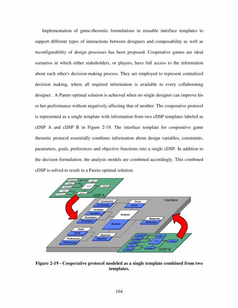
164
Implementation of game-theoretic formulations in reusable interface templates to
support different types of interactions between designers and composability as well as
reconfigurability of design processes has been proposed. Cooperative games are ideal
scenarios in which either stakeholders, or players, have full access to the information
about each other's decision-making process. They are employed to represent centralized
decision making, where all required information is available to every collaborating
designer. A Pareto optimal solution is achieved when no single designer can improve his
or her performance without negatively affecting that of another. The cooperative protocol
is represented as a single template with information from two cDSP templates labeled as
cDSP A and cDSP B in Figure 2-19. The interface template for cooperative game
theoretic protocol essentially combines information about design variables, constraints,
parameters, goals, preferences and objective functions into a single cDSP. In addition to
the decision formulation, the analysis models are combined accordingly. This combined
cDSP is solved to result in a Pareto optimal solution.
Goals
Goals
GoalsGoals
GoalsGoals
Preferences
Preferences
PreferencesPreferences
PreferencesPreferences
Variables
Variables
VariablesVariables
VariablesVariables
Parameters
Parameters
ParametersParameters
ParametersParameters
Constraints
Constraints
ConstraintsConstraints
ConstraintsConstraints
Response
Response
ResponseResponse
ResponseResponse
Objective
Objective
ObjectiveObjective
ObjectiveObjective
Analysis
Analysis
AnalysisAnalysis
AnalysisAnalysis
Driver
Driver
DriverDriver
DriverDriver
Interface
Goals
Preferences
Variables
Parameters
Constraints
Response
Objective
Analysis
Drive
r
GoalsGoals
PreferencesPreferences
VariablesVariables
ParametersParameters
ConstraintsConstraints
ResponseResponse
ObjectiveObjective
AnalysisAnalysis
Drive
r
Drive
r
Goals
Preferences
Variables
Parameters
Constraints
Response
Objective
Analysis
Drive
r
GoalsGoals
PreferencesPreferences
VariablesVariables
ParametersParameters
ConstraintsConstraints
ResponseResponse
ObjectiveObjective
AnalysisAnalysis
Drive
r
Drive
r
cDSP A
cDSP B
Figure 2-19 - Cooperative protocol modeled as a single template combined from two
templates.
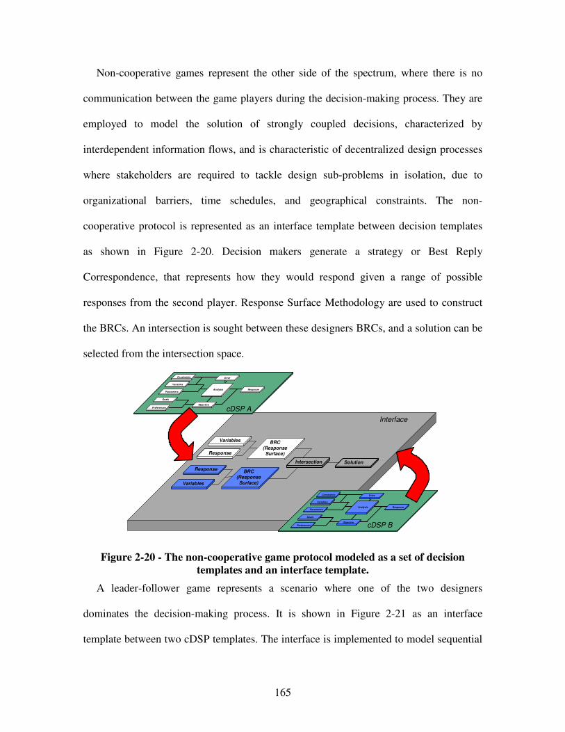
165
Non-cooperative games represent the other side of the spectrum, where there is no
communication between the game players during the decision-making process. They are
employed to model the solution of strongly coupled decisions, characterized by
interdependent information flows, and is characteristic of decentralized design processes
where stakeholders are required to tackle design sub-problems in isolation, due to
organizational barriers, time schedules, and geographical constraints. The non-
cooperative protocol is represented as an interface template between decision templates
as shown in Figure 2-20. Decision makers generate a strategy or Best Reply
Correspondence, that represents how they would respond given a range of possible
responses from the second player. Response Surface Methodology are used to construct
the BRCs. An intersection is sought between these designers BRCs, and a solution can be
selected from the intersection space.
Interface
Goals
Preferences
Variables
Parameters
Constraints
Response
Objective
Analysis
Drive
r
GoalsGoals
PreferencesPreferences
VariablesVariables
ParametersParameters
ConstraintsConstraints
ResponseResponse
ObjectiveObjective
AnalysisAnalysis
Drive
r
Drive
r
Goals
Preferences
Variables
Parameters
Constraints
Response
Objective
Analysis
Drive
r
GoalsGoals
PreferencesPreferences
VariablesVariables
ParametersParameters
ConstraintsConstraints
ResponseResponse
ObjectiveObjective
AnalysisAnalysis
Drive
r
Drive
r
cDSP A
cDSP B
ResponseResponse
ResponseResponse
BRC
(ResponseSurface)
VariablesVariables
VariablesVariables
BRC (Response
Surface)
IntersectionIntersection SolutionSolution
Figure 2-20 - The non-cooperative game protocol modeled as a set of decision
templates and an interface template.
A leader-follower game represents a scenario where one of the two designers
dominates the decision-making process. It is shown in Figure 2-21 as an interface
template between two cDSP templates. The interface is implemented to model sequential
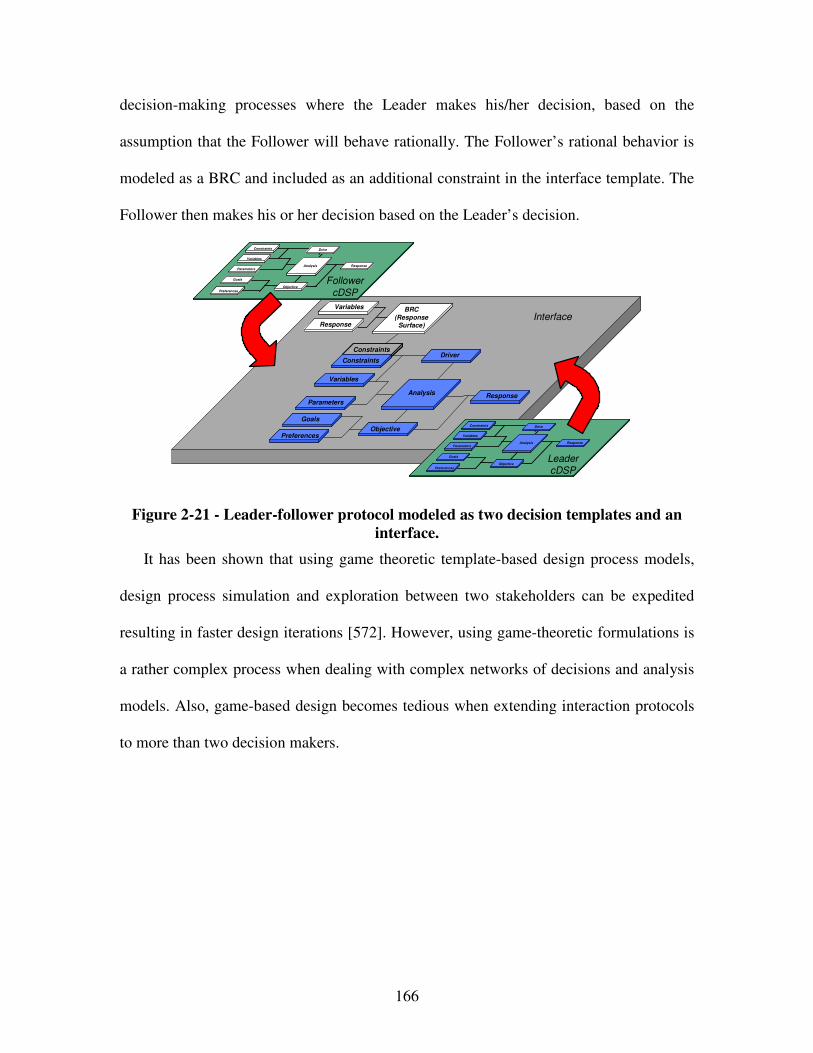
166
decision-making processes where the Leader makes his/her decision, based on the
assumption that the Follower will behave rationally. The Follower’s rational behavior is
modeled as a BRC and included as an additional constraint in the interface template. The
Follower then makes his or her decision based on the Leader’s decision.
GoalsGoals
PreferencesPreferences
VariablesVariables
ParametersParameters
Constraints
Constraints
ConstraintsConstraints
ConstraintsConstraints
ResponseResponse
ObjectiveObjective
AnalysisAnalysis
DriverDriver
Interface
Goals
Preferences
Variables
Parameters
Constraints
Response
Objective
Analysis
Drive
r
GoalsGoals
PreferencesPreferences
VariablesVariables
ParametersParameters
ConstraintsConstraints
ResponseResponse
ObjectiveObjective
AnalysisAnalysis
Drive
r
Drive
r
Goals
Preferences
Variables
Parameters
Constraints
Response
Objective
Analysis
Drive
r
GoalsGoals
PreferencesPreferences
VariablesVariables
ParametersParameters
ConstraintsConstraints
ResponseResponse
ObjectiveObjective
AnalysisAnalysis
Drive
r
Drive
r
Follower
cDSP
Leader cDSP
Response
BRC
(ResponseSurface)
Variables
ResponseResponse
BRC
(ResponseSurface)
VariablesVariables
Figure 2-21 - Leader-follower protocol modeled as two decision templates and an
interface.
It has been shown that using game theoretic template-based design process models,
design process simulation and exploration between two stakeholders can be expedited
resulting in faster design iterations [572]. However, using game-theoretic formulations is
a rather complex process when dealing with complex networks of decisions and analysis
models. Also, game-based design becomes tedious when extending interaction protocols
to more than two decision makers.
167
2.3.4 Metamodel-Based Design
Besides through interval-based and game-based design approaches, design-process
flexibility can be achieved through simplifying decisions and analysis models. In general,
design-processes can be simplified based on either approximations, metamodels or
decoupling interactions.
Approximations represent one solution to simplify computationally expensive
computer analyses that are usually available for use in the latter stages of design.
However, these analyses can be extremely computationally expensive for exploring broad
design spaces. Hence, approximations represent one solution to reduce computational
expense by sacrificing accuracy. However, when exploring large design spaces that
include broad ranges of design variables, repeated approximate simulations still generate
substantial computational loads.
Besides simplifying design-processes based on approximations, another approach is
to create metamodels, i.e., to create simple models of detailed (accurate) models in order
to replace computationally expensive computer analyses. Metamodeling facilitates
multidisciplinary multiobjective optimization, concept exploration and problem
clarification. It is crucial in times when the continual increased complexity of analysis
codes seems to keep pace with continual advanced in computing power [704].
Traditionally, as reviewed by Simpson and coauthors [603] or Wang and Shan [704],
metamodeling involves statistical approximations of detailed (accurate) simulations
through experimental designs (sampling methods) for generating data, model choices to
represent the data, and model fitting to the observed data, as summarized in Table 2-6.
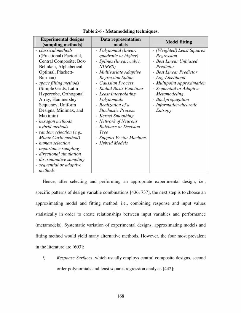
168
Table 2-6 - Metamodeling techniques.
Experimental designs
(sampling methods)
Data representation
models Model fitting
- classical methods ((Fractional) Factorial, Central Composite, Box-Behnken, Alphabetical Optimal, Plackett-Burman)
- space filling methods
(Simple Grids, Latin Hypercobe, Orthogonal Array, Hammersley Sequency, Uniform Designs, Minimax, and Maximin)
- hexagon methods
- hybrid methods
- random selection (e.g.,
Monte Carlo method)
- human selection
- importance sampling
- directional simulation
- discriminative sampling
- sequential or adaptive
methods
- Polynomial (linear,
quadratic or higher)
- Splines (linear, cubic,
NURBS)
- Multivariate Adaptive
Regression Spline
- Gaussian Process
- Radial Basis Functions
- Least Interpolating
Polynomials
- Realization of a
Stochastic Process
- Kernel Smoothing
- Network of Neurons
- Rulebase or Decision
Tree
- Support Vector Machine,
- Hybrid Models
- (Weighted) Least Squares
Regression
- Best Linear Unbiased
Predictor
- Best Linear Predictor
- Log-Likelihood
- Multipoint Approximation
- Sequential or Adaptive
Metamodeling
- Backpropagation
- Information-theoretic
Entropy
Hence, after selecting and performing an appropriate experimental design, i.e.,
specific patterns of design variable combinations [436, 737], the next step is to choose an
approximating model and fitting method, i.e., combining response and input values
statistically in order to create relationships between input variables and performance
(metamodels). Systematic variation of experimental designs, approximating models and
fitting method would yield many alternative methods. However, the four most prevalent
in the literature are [603]:
i) Response Surfaces, which usually employs central composite designs, second
order polynomials and least squares regression analysis [442];
169
ii) Neural Networks, i.e., which usually involves fitting a network of neurons by
means of back-propagating to data which is typically hand selected;
iii) Inductive Learning, i.e., which usually leverages a rulebase or decision tree
and information-theoretic entropy principles;
iv) Kriging, i.e., which usually deals with d-optimal experimental designs, the
realization of stochastic processes and best linear unbiased predictors [145,
359, 407].
Measures of merit for evaluating experimental designs include orthogonality,
rotatbility, minimum variance, and minimum bias, unsaturated/saturated and
supersaturated designs, as well as D-efficiency, as reviewed by Simpson and coauthors
[603]. However, the accuracy of the metamodel is determined by the experimental design
used to select data points, the approximating model and fitting method, the size of the
design space or range of explored values of design variables, the accuracy of the
simulation at each data point and the numbers of data points available to compute the
metamodel.
According to Qian and coauthors [521], other approaches to improve the accuracy
and computational efficiency of statistical approximation based metamodeling procedures
involve successively reducing the design space, thus, simultaneously reducing the extent
of the approximation of the metamodels. Methods to accomplish this include the use of
trust regions [15, 548, 741, 742], heuristics [116], move limits [669], entropy
maximization [197, 372], adaptive response surface methods [701, 702], and propose an
intuitive metamodeling method based on hierarchical fuzzy clustering proposed by Wang
and Simpson [703].
170
Since there can be a substantial computational cost involved in using data from
detailed simulations to build metamodels, a different approach to improve statistical
approximation based metamodel accuracy and computational efficiency is to use both
approximate and detailed (accurate) simulation. Osio and Amon propose a multistage
kriging method to sequentially update and improve model accuracy [464, 468]. Qian and
coauthors [521] propose an alternative method for aligning and enhancing a coarse model
with a fine model based on space mapping [38, 39] and a two-step Gaussian process
modeling. Their strategy is to run a large number of approximate simulations and a
smaller number of detailed simulations and then combine the two sets of results to
produce a final surrogate model. In other words, the accuracy of surrogate models
obtained from approximate simulations is improved by supplementing the data from the
approximate simulations with relatively few data points from more computationally
expensive detailed simulations. Thus, it is possible to explore a design space with
improved or enhanced surrogate models that are more accurate than surrogate models
based entirely on approximate simulations but less computationally expensive than
surrogate models based exclusively on detailed simulations.
Another statistical approximation based way of reducing the design space is by
reducing its dimensionality [70]. Typically, the design space is screened to identify and
remove design variables that are less important. According to Qian and coauthors [521],
both group-screening [714] and sequential bifurcation [57, 58] must be applied cautiously
for design in which multiple responses are considered; screening using supersaturated
statistical experimental designs is preferable for situations with multiple response [269,
736].
171
It is widely recognized that when the number of design variables is large (such as for
largescale [330] or multiscale [475] problems), the total computational expense for
statistical approximation based metamodeling techniques makes the approaches less
attractive or even infeasible [704]. Then, decomposition strategies for systems design
might become attractive to support traditional statistical approximation based
metamodeling. Also, “flexible metamodeling” and “intelligent sampling” are focus of
current research efforts [704].
2.3.5 Design-Process Design Based on Information Economical Principles
In general, design-processes can be designed using various metrics. Direct metrics for
example relate directly to a designer’s preferences, such as cost, execution time,
accuracy, design freedom [601], etc. On the other hand, indirect metrics, related to direct
metrics, include concurrency [352], complexity, uncertainty, stability, convergence,
robustness, modularity, and reconfigurability. However, often direct or indirect metrics
cannot readily or rigorously be evaluated. Hence, the common approach to designing
design-processes is based on simplifying design-processes by decomposing a system
level problem into independent sub-problems by either re-sequencing tasks (if there is no
coupling), identifying and removing weak couplings between decisions and analysis
models, or use simplified analysis models within the network of decisions and models.
Various approaches to quantify the strength of couplings in different ways [104, 351,
502] or the sensitivity of system level outputs to system level inputs [64, 65, 183, 184,

172
247, 283, 549, 619] for identifying and removing weak couplings have been proposed.
The effectiveness of these scale-, matrix- or sensitivity-based approaches however
reduces drastically when dealing with i) complex design processes, ii) highly non-linear
or discontinuous objective functions, or iii) large changes in design variables.
In order to address the shortcomings of the approaches reviewed above, a class of
metrics referred to as value-of-information derived from the field of information
economics has been developed. Information Economics [31, 33, 476] is defined as “…the
study of choice in information collection and management when resources to expend on
information collection are scarce” [31]. It was first introduced by Howard [274]. Many of
the information economics principles have been developed and employed previously in
economics, as reviewed by Lawrence [361]. The area of information economics grew out
of statistical decision theory in the 1950s [396]. Current areas of research focus on
corporate finance and industry policy [554] or on the infusion of information technology
into enterprises [637].
Within engineering, the focus of information management has been primarily on data
exchange, interoperability, and visualization to support collaborative design [34]. Review
articles are given by Ciocoiu et al. [136], Rangan and Chadha [526], and Syzkman et al.
[654]. The key difference between engineering design applications and economics
applications is the availability of perfectly known probability distributions that engineers
often lack in practice [34].
As noted by Panchal [475], information economics is used to study the effect of
information on decisions. In information economics, the decisions are formulated as
follows – the designer wants to select from a specific action a from a set of possible

173
actions a in the presence of uncertain variable x [361]. The objective is to select an
appropriate value of the action a = a0 such that some form of payoff is maximized. The
payoff function π(x,a) depends on the combination of a, the action that decision maker
chooses and x, the ultimate realization of the uncertain variable. The key challenge in
decision making is due to the fact that a designer has to make decisions before the
realization of state x. But, the designer does not have complete information about the
realization of state x.
Therefore, the designer has two options – i) he/she can either make a decision based
on the available knowledge about the probability distribution of x, or ii) he/she can gather
additional information that changes the decision maker’s probability distribution over the
possible values that x can take. This additional information is received from an
‘information source’. If the decision maker selects the first option and goes ahead with
the first option and makes a decision using the available information about x, then he/she
can select the value of action a that maximizes the expected value of the payoff. If the
decision maker selects the second option, then he/she must determine whether the cost of
gathering additional information is greater than the benefit achieved by gathering
additional information. Hence, there is a tradeoff between cost of information and the
benefit achieved by it. This tradeoff is quantified by various “value-of-information”
metrics.
Lawrence [361] and Panchal [475] provide a comprehensive overview of metrics for
value of information. In general, value of information based metrics are used by decision
makers to make the meta-level decision involving tradeoff between gathering more
information to reduce uncertainty (increase accuracy) and reducing the associated cost
174
(decreasing computational efficiency). For example, value-of-information-based design
leverages a class of metrics that refer to the difference between the outcomes of decisions
made using a non-simplified design process and the outcome achieved using a simplified
design process.
The primary concern treated in this vein is thus that of making a cost-benefit trade-off
associated with obtaining (additional) information. Costs are incurred through the
expenditure of resources (e.g., via modeling, experimentation, etc.). Value is determined
with respect to effectiveness in reducing uncertainty. For example, while complex design
processes that consider all interactions lead to better designs, simpler design processes
are faster. Also, model uncertainty (due to approximations and assumptions chosen
during model development) may or may not affect design decisions depending on the
impact of designers’ preferences that act on the outputs of simulation models.
2.3.6 Limitations and Use of Methods and Tools for Achieving Design-Process Flexibility in this Dissertation
Having reviewed methods and tools to enhance a designer’s flexibility, i.e., advanced
metamodeling, interval, game-theoretic, optimization-based, and value-of-information-
based design approaches in particular, limitations and use of these approaches are
summarized in Table 2-7. The methods and tools to enhance a designer’s flexibility are
particularly useful for certain scenarios, as reviewed in above. However, when facing
design-processes comprised of a complex network of decisions and analysis models,
except for value-of-information-based design, these approaches are severely limited with
175
respect to the problem of size, system-level bottlenecks, computational intractability, or
highly nonlinear and discontinuous design spaces.
Table 2-7 - Limitations and use of methods and tools to achieving design-
process flexibility in this dissertation.
Research Effort Limitations Use in this Dissertation
Optimum-solution-
based design [92, 143, 245, 328, 345, 618, 620, 663, 739]
When combining solutions to subproblems and facing the problem of size or highly nonlinear and discontinuous design spaces, optimum single-point solutions are mostly far less than optimal in the context of solving integrated multilevel and multiscale design problems.
Can be used for hierarchical cDSP formulations in scenarios where a complex network of decisions and analysis models is encountered.
Interval-based design
[92, 102, 475, 577] Often limited with respect to centralized, system-level optimization that creates system-level bottlenecks and computational intractability.
Can be used for generating design-process alternatives by decoupling decisions or analysis models in complex networks of decisions and models.
Game-based design [4, 5, 118, 206, 368, 397, 398, 400, 401, 515, 697]
Often limited with respect to the problem of size or highly nonlinear and discontinuous design spaces.
Can be used for solving coupled design-processes in scenarios when functional decomposition is not applicable.
Metamodel-based
design [15, 38, 39, 57, 58, 70, 116, 145, 197, 269, 330, 359, 372, 407, 436, 442, 464, 468, 521, 548, 603, 669, 701-704, 714, 736, 737, 741, 742]
Often limited with respect to the problem of size or highly nonlinear and discontinuous design spaces.
Fundamentals of metamodeling are used for generating design-process alternatives and evaluating the Process Performance Indicator.
Value-of-information-
based design [31, 33, 64, 65, 104, 183, 184, 247, 283, 351, 352, 476, 502, 549, 601, 619]
Limited to scenarios where knowledge of a truthful design-process or its error bounds is known throughout the whole design space.
Are extended in this dissertation to be used for systematic design-process generation and selection for scenarios in which knowledge of a truthful design-process or its error bounds is not known throughout the whole design space
176
In order to manage uncertainty and complexity in the complex network of decisions
and analysis models encountered during the integrated design of product and materials,
value-of-information-based approaches are further investigated in Chapter 5.
2.4 Methods and Tools to Achieve Product Flexibility
Yet another area of research addressing a designer’s flexibility after a system is
fielded is product flexibility. In this dissertation, product flexibility is defined as the
ability to realize open engineering systems and “respond to changes in [the system’s]
initial objectives and requirements – both in terms of capabilities and attributes –
occurring after the system has been fielded, i.e., is in operation, with ease in a timely and
cost-effective way” with ease [560]. Methods and tools to achieve product flexibility are
reviewed in this section to show how they can be used within the systematic approach to
integrated product, materials, and design-process design and in the context of adaptive
design.
Product flexibility maps to the ability to realize open engineering systems, described
by Simpson, Lautenschlager and Mistree as “systems of industrial products, services
and/or processes that are readily adaptable to changes in their environment which enable
producers to remain competitive in a global marketplace through continuous
improvement and indefinite growth of an existing technology base” [597]. The product
flexibility indicators: i) time and ii) cost required to implement changes in system
177
architectures proposed in this dissertation are in line with the statement that by
maintaining design freedom and increasing design knowledge, a product’s flexibility
enhanced [597]. Hence, product flexibility allows companies to respond and continuously
improve their products in an effective and efficient way after the system has been fielded
in response to dynamic demands.
As proposed by Simpson, Lautenschlager and Mistree, product flexibility can be
achieved through design for one of three characteristics: i) modularity, ii) mutability, or
iii) robustness. Design for modularity also involves design for mass customization as well
as product platforms and families. Also, design for mutability involves design for
standardization, a well established approach for enhancing product flexibility as for
example described by Uzumeri and Sanderson [687]. However, methods and tools to
achieve product flexibility are reviewed in Section 2.4.1 with respect to design for
modularity, in Section 2.4.2 with respect to design for mutability, and in Section 2.4.3
with respect to design for robustness. Combinations of design for modularity, mutability
and robustness especially in the context of reconfigurable systems design are discussed in
Section 2.4.4. A summary of how methods and tools to achieve product flexibility are
used in this dissertation is presented in Section 2.4.5.
2.4.1 Design for Modularity
Design for modularity is a common approach to achieve product flexibility.
According to Simpson and coauthors [597], “modularity it the relationship between a
178
product’s functional and physical structures such that there is (a) a one-to-one
correspondence between the functional and physical structures and (b) a minimization of
unintended interactions between modules. Modularity allows the product to be used in
different ways (i.e. changing functions) and may facilitate the rearrangement/replacement
of physical components (i.e. changing form).” Modularity however requires a modular
architecture, which according to Ulrich [682, 684] has the properties that i) chunks
implement one or a few functional elements in their entirety, and ii) The interactions
between chunks are well defined and are generally fundamental to the primary functions
of the product. Hence, a truly modular architecture is one in which each “chunk” of the
overall systems accomplishes one specific function and the interface between chunks is
well defined. Thus, modular product architectures are those with one-to one functional to
physical mapping combined with standardized, uncoupled interfaces between
components [560].
Modular product architectures and configuration design techniques can be utilized to
achieve product flexibility. The goal is to design flexible products that can be readily
adapted in response to large changes in customer requirements by modifying a small
number of components or modules. These products may then fulfill different functions
through the combination of distinct building blocks or modules. Hence, they facilitate
interchanging components to perform different functions through altering only a portion
of the existing product. Thus, design for modularity is important for realizing functionally
distinct families of products or for upgrading products.
The advantage of modular architectures is that a change to one “chunk” can be made
without requiring a change to the other “chunks”, in effect offering some amount of
179
flexibility to designers [622]. However, as Olewnik and coauthors [458] point out, if a
design is too modular (needs different “chunks” for each situation) it may not be flexible
enough. However, a modular design can be used to change or develop a system over time
without having to redesign the entire system. Single or multiple modules can be
effectively replaced and updated, resulting in product flexibility. Modular Function
Deployment [470] or the definition of modules at the function level strongly supports the
modularization of products. Other customization approaches involve adjustable designs,
dimensional customization or dimensional standardization in order to keep the dimension
of interfaces between modules standardized. Hence, design for mass customization is
crucial when designing for modularity.
The focus of design for mass customization is on the quick responsiveness to achieve
product flexibility and customization by fragmented demand, heterogeneous niches, low
cost, high quality, customized goods and services and short product development and life
cycles. Design for mass customization gives the designer a methodology by which
products and processes can be customized for the customer or market segment, all the
while maintaining speeds, efficiencies and costs similar to that off mass production and
maintaining limited inventories and forecasts for demand [22, 198, 501, 503, 597, 674].
Mass customization requires variety within the product. Of the two types of variety –
external variety, i.e., the variety that the customer is aware of, and internal variety, i.e.,
the variety viewed by production and distribution operations – mass customization seeks
to maximize external variety (variety of options for customers) and minimize internal
variety (cost to the company).
180
External variety can be useful or useless. Useful variety is appreciated by customers
and should therefore be maximized within cost, quality and speed capabilities. Useless
variety is transparent, unimportant or confusing to customers and should be eliminated.
More variety includes additional costs (e.g. cost of customizing or configuring products,
cost of excessive parts, …). Cost of variety is the sum of all the costs of attempting to
offer customers variety with inflexible products that are produced in inflexible factories
and sold through inflexible cannels. The challenge is to provide increased product variety
for the marketplace with as little variety between products as possible in order to
maintain the requisite economies of scale (and scope) needed to remain profitable. Hence,
it must be thoroughly examined, what kind of customization customers value. Gilmore
and Pine [234] propose four distinct approaches to customization, which are called
collaborative, adaptive, cosmetic and transparent. The four approaches to customization
provide a framework for companies to design customized products and supporting
business processes. However, to reduce especially internal variety costs design for mass
customization implies design of product platforms and families.
Product platforms – a set of common components, modules or parts from which a
stream of derivative products can be created [364] – provide a way of creating ordinary
products which can be customized to satisfy individual customer specifications while
maintaining costs and speeds close to those of mass production [503]. The importance of
product platforms and product families – groups of related products that are derived from
product platforms – is stressed in the literature [22, 503, 600]. Moreover, examples of
successful product platforms and derived product families are published [198, 494, 563,
573, 684, 755]. The product developing map [720], product family map [422] and market
181
segmentation grid [423] are attention directing approaches to product platform design.
Various systematic engineering approaches to develop product platforms have been
proposed. According to Simpson, most of these approaches can be classified as “top
down” or “bottom up” approaches [600]:
• Top-down (a priori) approaches: a company strategically manages and develops a
family of products based on a product platform and its derivatives.
• Bottom-up (a posteriori) approaches: a company redesigns or consolidates a
group of distinct products to standardize components to improve economies of
scale.
General top down approaches to product platform design have been developed [119,
187, 222, 403-405, 546, 635, 673, 674]. Additional top down platform design approaches
focusing on scaling product platforms into derivative products for a product family to
provide variety have been proposed in the literature [139, 264, 266, 446-448, 553, 557,
598]. Instead of focusing on scaling, other researchers focus on the implications of
modularity on product variety [149, 188, 223, 224, 237, 452, 470, 550, 563, 680, 682,
683, 687, 723, 758, 761].
General bottom up approaches building on knowledge of existing systems to develop
product platforms have been proposed in the literature [287, 592]. Clustering bottom up
approaches focusing on similarity or commonality of products can also be found in the
literature [589, 630, 672]. However, Pedersen developed a new engineering approach to
design hierarchical product platforms based on similarity or commonality within complex
engineering systems [495].
182
Since product platforms tend to have lifetimes that exceed the lifetime of the variants
that are derived from them [604], hierarchical platforms built on modular system
architectures become crucial to increase a designer’s flexibility after a system is fielded,
i.e., in its operation. Definitions and a domain independent approach to hierarchical
platform design based on the systematic scientific method of numerical taxonomy is
presented in the literature [420, 496].
2.4.2 Design for Mutability
Design for mutability is another common approach to achieve product flexibility.
According to Simpson and coauthors [597], “mutability is the capability of the system to
be contorted or reshaped in response to changing requirements or environmental
conditions. Mutability implies a change in form but does not indicate a change in
function.” Design for mutability includes standardization and parametric design
(dimensional standardization) approaches through which products, modules and
interfaces are standardization but can be contorted or reshaped.
For example, some standardization approaches [287, 470, 591] are based on
cataloguing parts that are similar in manufacturing and design function (group
technology) or by determining part commonality with the help of Pareto plots (for
products lines with few products, part usage volume is the dominant criterion for
communalization; conversely for product lines with many products, the dominant
criterion is the number of products that use each part). Standardization and design to
183
standards is an important aspect of product variety design and is closely related to the
development of product platforms – i.e., the common structure of a family of products. In
standardization, parts, interfaces, dimensions and manufacturing processes are made
common across a product line. While increasing standardization may lead to efficiency
savings due to enhanced quality, reduced inventories, and increased returns on
investment, it could also lead to increased complexity of component parts and declining
flexibility in meeting a range of desired performance specifications. Standardization is
possible when a component implements commonly useful functions or the interface to the
component is identical across more than one product. Modular architecture increases the
likelihood of standardization.
Parametric design approaches generally imply a change in form. Size ranges for
example are commonly used for parametric design. They provide a rationalization of
design and production procedures. Their aim is the rationalization of product
development by the implementation of the same function with the same solution principle
and if possible with the same properties and similar product processes over a wider range
of sizes. In the development of size range, it is essential to make use of similarity laws
and decimal-geometric preferred number series [470]. Geometric similarity ensures
simplicity and clarity of design. Similarity exists, if the relationship of at least one
physical quantity in the basic and sequential designs is constant. A similarity, where the
ratio of all the lengths of any sequential design to all the lengths of the basic design is
constant, is called geometric similarity. Besides geometric similarity, special similarities
such as semi-similar size ranges exist.
184
2.4.3 Design for Robustness
According to Simpson and coauthors [597], “robustness implies an insensitivity to
small variations and does not dictate a change in form nor change in function.” Design
for robustness is a means to allow a system to satisfy a fixed set of system requirements
despite stochastic changes to the operating environment by designing the system mto be
insensitive to such possible disturbances. In an omnipresence of disturbing effects
causing desired or undesired side effect, probability-based robust design methods [117]
enable a designer to create systems that are less sensitive to various sources of
uncertainty than systems created through traditional optimization methods. In other
words, robust design enables a designer to find satisficing solutions and hence increase
product flexibility under the assumption that once decided upon, the design will not
change as it is operated.
Robustness implies an insensitivity to small variations (in external conditions) and
does not dictate a change in form nor a change in function (robust over a range).
According to Saleh and coauthors [560], a general definition of robustness is synthesized
as “the property of a system which allows it to satisfy a fixed set of requirements, despite
changes occurring after the system has entered service, in the environment or within the
system itself, from the nominal or expected environment or the system design parameters
(i.e., the key physical variables that characterize a design and satisfy a set of specified
requirements).” Adaptability on the other hand deals with predictable changes in
operating conditions. Hence, the objective of robust design is to maintain a target
185
performance despite various noise factors (e.g., variations in the conditions of use of the
system, degradation of the system with time, manufacturing variability, etc.). The
objective of robust control on the other hand is to ensure stability and maintain some pre-
defined performance specifications.
The goal of robust control concerning model uncertainty is that a control system must
operate properly in realistic situations despite the fact that mathematical representations
of systems often involves simplifying assumptions, complicated dynamics in high
frequencies or unknown nonlinearities. Robust control tools to handle disturbances and
model uncertainty in systems to be controlled have been proposed by Francis [214],
Doyle and coauthors [172], Ackerman [9], Dahleh and coauthors [148], as well as
Sanchez-Pena and coauthors [561]. According to Stefani and coauthors [632], from a
system’s control perspective “the ultimate goal of a control-system designer is to build a
system that will work in the real environment. Since the real environment may change
with time – components may age or their parameters may vary with temperature or other
environmental conditions – or the operating conditions may vary – load change,
disturbances – the control system must be able to withstand these variations.”
As described above, the goal of robustness is to manage uncertainty (for example in
noise parameters, design variables or simulation models) to satisfy a fixed set of
performance requirements when dealing with unpredictable changes in operating
conditions. A thorough literature review of design under uncertainty has been conducted
by Choi [129]. In general, uncertainty can be epistemic (i.e., reducible uncertainty or
imprecision due to ignorance of information) or aleatory (i.e., irreducible uncertainty or
variability) in nature. However, for managing uncertainty in design, two primary
186
approaches have been identified: (i) reducing the uncertainty itself, and (ii) designing a
system to be less sensitive to uncertainty without necessarily reducing or eliminating it.
For a detailed review and discussion of both approaches the reader is referred to Choi
[129]. However, reducing uncertainty is feasible when a designer has large amounts of
data or even better complete knowledge. The common underlying hypothesis is that it is
possible to obtain true (or approximately true) data. This hypothesis, however, is not
valid in many integrated product and materials design problems due to aleatory
uncertainty. Therefore, the approach of designing a system to be less sensitive to
uncertainty without eliminating or reducing its sources in the system – called robust
design (or parameter design) – is crucial to achieve satisficing solutions and hence
product flexibility.
Historically, robust design was used to make the system response insensitive to
uncontrollable system parameters, thus improving product quality, as proposed by
Taguchi [656-658]. Taguchi developed a design methodology in order to make a
product’s performance insensitive to raw material variation, manufacturing variability,
and variations in the operating environment. It builds upon ideas from statistical
experimental design. Robustness is a characteristic of a system that minimizes deviations
keeping performance economically close to ideal customer satisfaction. Ideal customer
satisfaction in this context is that every product delivers the target performance each time
the product is used, under all intended operating conditions, and throughout its intended
lifetime. In the robust design literature, system parameters are typically divided into three
categories: control factors, noise factors, and responses. Control factors, also known as
design variables, are system parameters that a designer may adjust. Noise factors on the
187
other hand are exogenous parameters that affect the performance of a product or process
but are not under a designer’s control. Responses are performance measures for the
product or process.
Although Taguchi’s robust design principles are advocated widely in both industrial
and academic settings, his statistical techniques have been criticized extensively. Also,
Taguchi’s robust design focuses only on performance variation due to noise variables.
Moreover, improving the statistical methodology has been an active area of research (e.g.,
[113, 442, 444, 675, 676]). During the past decade, a number of researchers have
extended robust design methods for a variety of applications in engineering design (e.g.,
[85, 112, 113, 118, 409, 466, 467, 488, 640, 757]). However, most of the robust design
literature is focused on the latter portions of embodiment and detail design. For the early
portions of embodiment design, for which especially control factors are also subject to
changes, Chen [111] developed a robust design approach that accounts for the objective
of minimization of variation in response due to variation in both control factors and noise
factors. Their domain-independent, systematic approach, the Robust Concept Exploration
Method (RCEM), integrates statistical experimentation and approximate models, robust
design techniques, multidisciplinary analyses, and multiobjective decisions modeled as
cDSPs for determining the values of design variables that satisfy a set of constraints and
balance a set of conflicting goals, including bringing the mean on target and minimizing
variation associated with each performance parameter. Also, the number of decision
variables in complex engineering is reduced through screening, the computational
expense is decreased through metamodeling and multiple objectives as well as
uncertainty are handled through robust design using the DSP Technique. Moreover, by
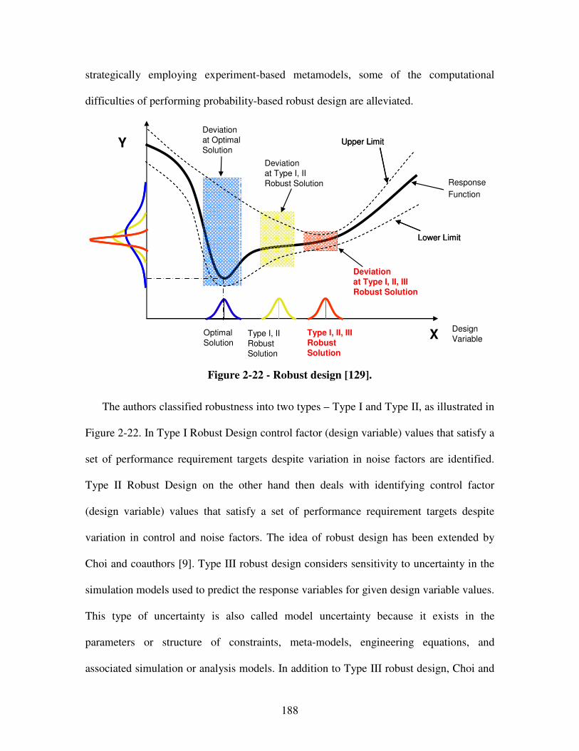
188
strategically employing experiment-based metamodels, some of the computational
difficulties of performing probability-based robust design are alleviated.
Y
XType I, II, IIIRobustSolution
Upper Limit
Lower Limit
Upper Limit
Lower Limit
Response
Function
Deviation
at Optimal
Solution
Deviation
at Type I, II
Robust Solution
Deviationat Type I, II, III Robust Solution
Design
VariableType I, II
Robust
Solution
Optimal
Solution
Figure 2-22 - Robust design [129].
The authors classified robustness into two types – Type I and Type II, as illustrated in
Figure 2-22. In Type I Robust Design control factor (design variable) values that satisfy a
set of performance requirement targets despite variation in noise factors are identified.
Type II Robust Design on the other hand then deals with identifying control factor
(design variable) values that satisfy a set of performance requirement targets despite
variation in control and noise factors. The idea of robust design has been extended by
Choi and coauthors [9]. Type III robust design considers sensitivity to uncertainty in the
simulation models used to predict the response variables for given design variable values.
This type of uncertainty is also called model uncertainty because it exists in the
parameters or structure of constraints, meta-models, engineering equations, and
associated simulation or analysis models. In addition to Type III robust design, Choi and
189
co-authors presented an Inductive Design Exploration Method (IDEM), which is focused
on the propagation and potential amplification of uncertainty due to combined effects of
analysis tasks performed in series or parallel.
2.4.4 Combinations – Design for Reconfigurability
In the context of design for reconfigurability, design for modularity, mutability, and
robustness is often combined to achieve the design of reconfigurable systems. According
to Olewnik and coauthors [457], reconfigurable systems are designed to maintain a high
level of performance by changing their configuration to meet multiple functional
requirements or a change in operating conditions. Similarly, according to Siddiqi,
reconfigurable systems achieve a desired outcome within acceptable reconfiguration time
and cost [590]. In this context, product flexibility is often defined as a combination of
modularity, mutability, and robustness. For example, Ferguson and coauthors define
product flexibility as “the property of a system that promotes change in both the design
(form) and performance (function) space”, where change in the design (form) space is
characterized by changes in mass, length, and time, and change in the performance
(function) space is characterized by change in multi-ability, evolution, and robustness
[200].
Methods and tools to design for reconfigurability have been reviewed by Ferguson
and coauthors [200]. In addition to the methods and tools that facilitate design for
modularity, mutability, and robustness, they include transformer design theory [606,
190
609], Change Mode Effects Analysis (CMEA) [320, 525], Change Propagation Analysis
(CPA) [137, 152, 177, 303, 664, 735], and compliant mechanisms [379]. However,
fundamental to design for reconfigurability are design for modularity, mutability, and
robustness as reviewed in the previous sections. Hence, focus in this dissertation is on
design for modularity, mutability, and robustness to achieve product flexibility.
2.4.5 Use of Methods and Tools for Achieving Concept Flexibility in this Dissertation
Methods and tools to achieve product flexibility, compatible with the systematic
approach to integrated product, materials, and design-process design developed in this
dissertation, have been reviewed. The use of these methods and tools in the context of
this dissertation is summarized in Table 2-8. However, as argued in Chapter 6, methods
and tools to achieve product flexibility facilitate adaptive design. Since adaptive design
outnumber original design by far, these methods and tools to achieve product flexibility
are recommended to use when applying the systematic approach developed in this
dissertation whenever applicable and feasible in the given problem context.
2.5 Role of Chapter 2 in this Dissertation
Having introduced and reviewed the theoretical foundations based on which the
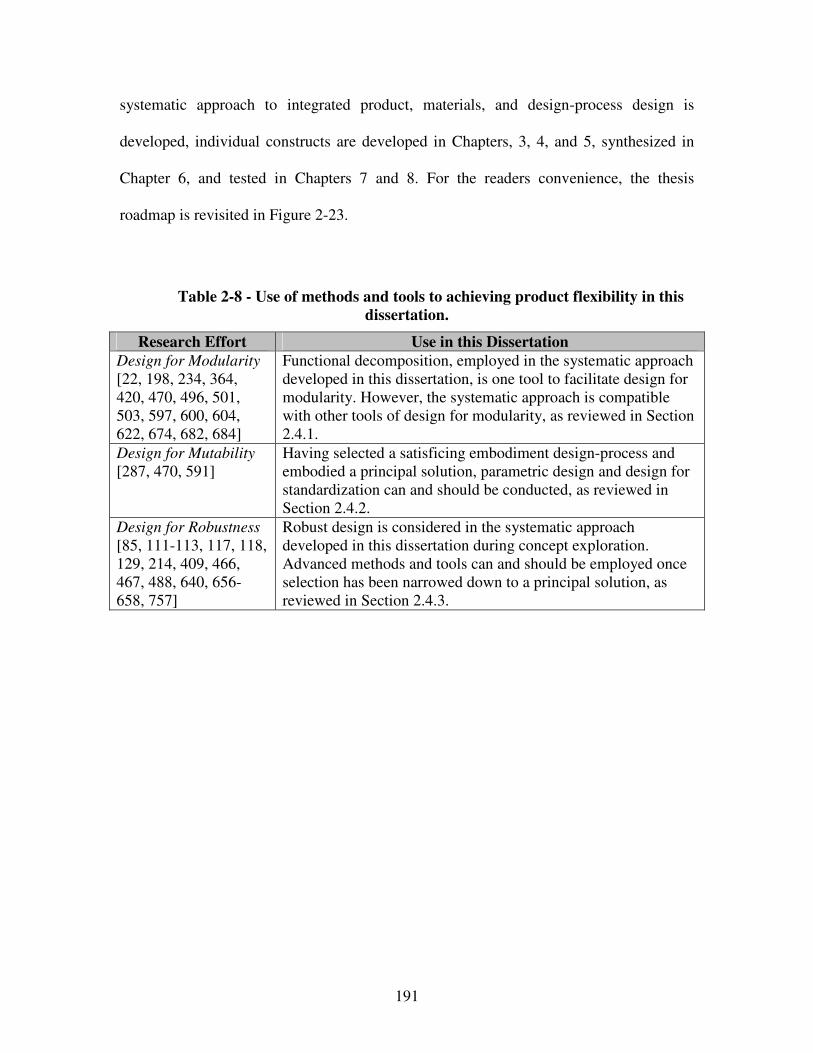
191
systematic approach to integrated product, materials, and design-process design is
developed, individual constructs are developed in Chapters, 3, 4, and 5, synthesized in
Chapter 6, and tested in Chapters 7 and 8. For the readers convenience, the thesis
roadmap is revisited in Figure 2-23.
Table 2-8 - Use of methods and tools to achieving product flexibility in this
dissertation.
Research Effort Use in this Dissertation
Design for Modularity
[22, 198, 234, 364, 420, 470, 496, 501, 503, 597, 600, 604, 622, 674, 682, 684]
Functional decomposition, employed in the systematic approach developed in this dissertation, is one tool to facilitate design for modularity. However, the systematic approach is compatible with other tools of design for modularity, as reviewed in Section 2.4.1.
Design for Mutability
[287, 470, 591] Having selected a satisficing embodiment design-process and embodied a principal solution, parametric design and design for standardization can and should be conducted, as reviewed in Section 2.4.2.
Design for Robustness
[85, 111-113, 117, 118, 129, 214, 409, 466, 467, 488, 640, 656-658, 757]
Robust design is considered in the systematic approach developed in this dissertation during concept exploration. Advanced methods and tools can and should be employed once selection has been narrowed down to a principal solution, as reviewed in Section 2.4.3.
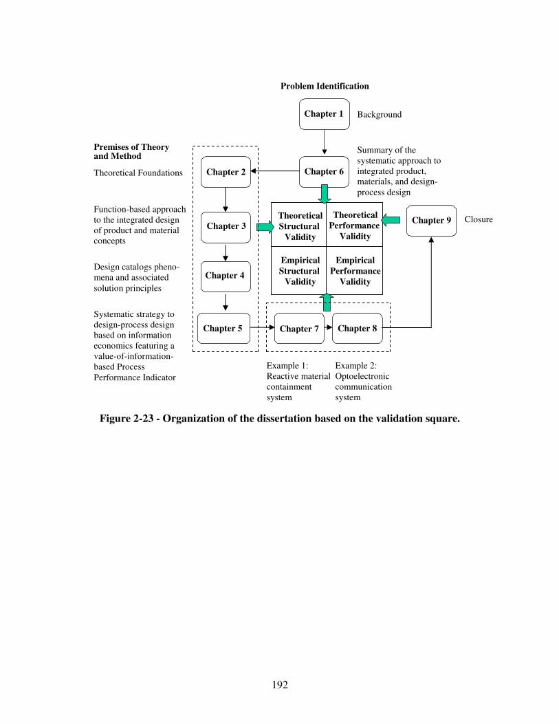
192
Figure 2-23 - Organization of the dissertation based on the validation square.
Theoretical Structural
Validity
Empirical Structural
Validity
Theoretical Performance
Validity
Empirical Performance
Validity
Chapter 6 Chapter 2
Chapter 8
Chapter 9
Chapter 1
Chapter 3
Problem Identification
Premises of Theory and Method
Background
Example 1: Reactive material containment system
Theoretical Foundations
Closure
Chapter 5
Chapter 4
Function-based approach to the integrated design of product and material concepts
Systematic strategy to design-process design based on information economics featuring a value-of-information-based Process Performance Indicator
Design catalogs pheno-mena and associated solution principles
Summary of the systematic approach to integrated product, materials, and design-process design
Chapter 7
Example 2: Optoelectronic communication system
193
Chapter 3 Systematic Function-based Approach to the Integrated Design of Product and Material
Concepts
In this chapter, the requirements for the systematic approach – “increasing a
designer’s concept flexibility”, “integrating design of product and material concepts”,
“rendering conceptual materials design more systematic”, and “providing systematic,
modular, reconfigurable, reusable, domain-independent, archivable, and multi-objective
decision support” – are addressed. All requirements for the systematic approach are listed
in Table 1-6. The constructs of the systematic approach developed to address these
requirements are highlighted in Figure 3-1. A portion of Table 1-6 that is relevant to this
chapter is reproduced in Table 3-1. The component of the systematic approach developed
in this chapter is a systematic, function-based approach for the integrated design of
product and material concepts. The reactive material containment system example is used
in Chapter 7 for validation of this component of the systematic approach. The systematic
function-based approach is used for answering Research Questions 1 and 2 posed in this
dissertation. Its relationship with the research questions and the supporting hypotheses is
presented in Figure 3-1.
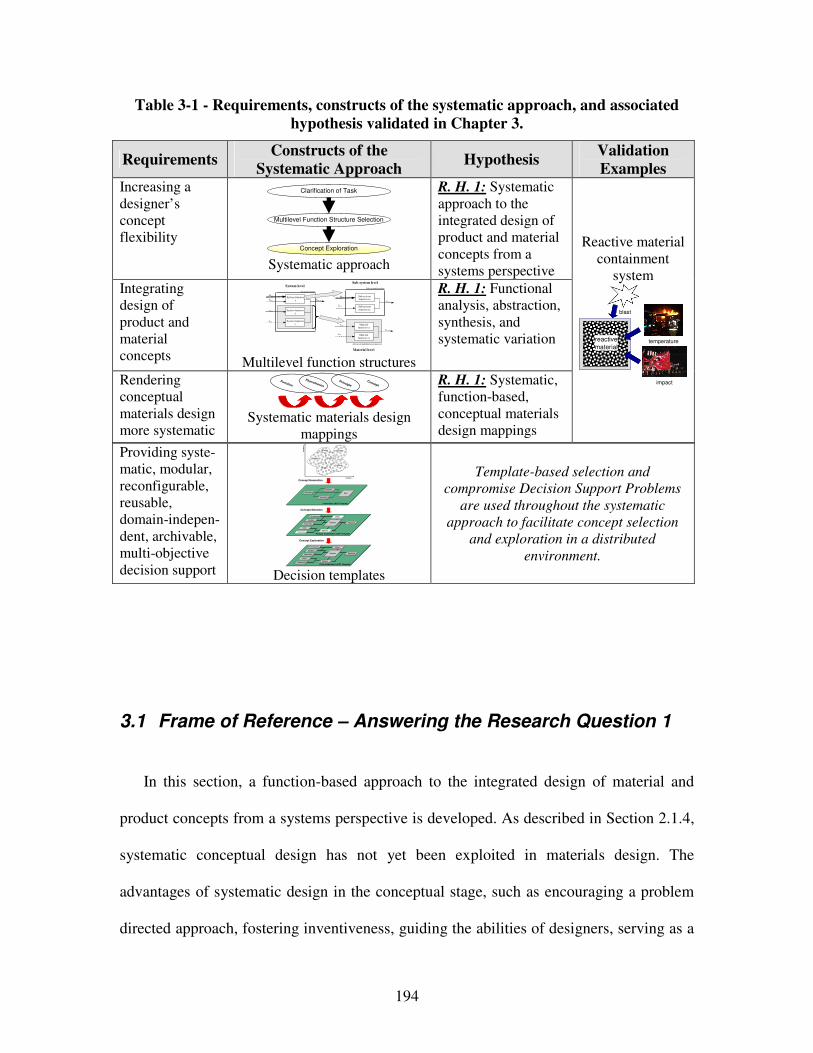
194
Table 3-1 - Requirements, constructs of the systematic approach, and associated
hypothesis validated in Chapter 3.
Requirements Constructs of the
Systematic Approach Hypothesis
Validation
Examples Increasing a designer’s concept flexibility
Multilevel Function Structure Selection
Clarification of Task
Concept Exploration Systematic approach
R. H. 1: Systematic approach to the integrated design of product and material concepts from a systems perspective
Integrating design of product and material concepts
Advanced mult ifunctional materia l
Ex,in
Mx,in
Ex,in
System boundary
System function x Exyz,out
System function z
System function y
Ey,in
Sz,in
Mx,in Sub-system function xx
Ex,out
Sub-system function xy
Sz,in
Ey,in Material function yx
Eyz,out
Material function zx
Sub-system boundary System level
Sub-system level
Material level Multilevel function structures
R. H. 1: Functional analysis, abstraction, synthesis, and systematic variation
Rendering conceptual materials design more systematic
Systematic materials design
mappings
R. H. 1: Systematic, function-based, conceptual materials design mappings
Reactive material containment
system
temperature
impact
reactive
material
blast
Providing syste-matic, modular, reconfigurable, reusable, domain-indepen-dent, archivable, multi-objective decision support
Concept Generation
Concept Selection
Concept Exploration
Alternatives Rank
Instantiated sDSP Template
Importance
Attributes
Goals
Preferences
Variables
Parameters
Constraints
Response
Objective
Analysis
Driver
Fully Instantiated cDSP Template
Goals
Preferences
Variables
Parameters
Constraints
Response
Objective
Analysis
Driver
Partially Instantiated cDSP Template
Att
rib
ute
2
Attribute 1
Concept 2
Concept 5
Concept 1 Concept 3
Concept 6
Concept 4
Decision templates
Template-based selection and
compromise Decision Support Problems
are used throughout the systematic
approach to facilitate concept selection
and exploration in a distributed
environment.
3.1 Frame of Reference – Answering the Research Question 1
In this section, a function-based approach to the integrated design of material and
product concepts from a systems perspective is developed. As described in Section 2.1.4,
systematic conceptual design has not yet been exploited in materials design. The
advantages of systematic design in the conceptual stage, such as encouraging a problem
directed approach, fostering inventiveness, guiding the abilities of designers, serving as a
Concept
Principle
Phenomenon
Function
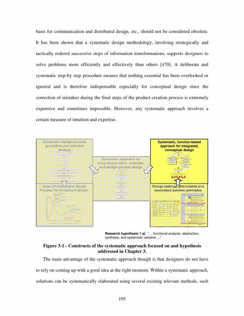
195
basis for communication and distributed design, etc., should not be considered obsolete.
It has been shown that a systematic design methodology, involving strategically and
tactically ordered successive steps of information transformations, supports designers to
solve problems more efficiently and effectively than others [470]. A deliberate and
systematic step-by step procedure ensures that nothing essential has been overlooked or
ignored and is therefore indispensable especially for conceptual design since the
correction of mistakes during the final steps of the product creation process is extremely
expensive and sometimes impossible. However, any systematic approach involves a
certain measure of intuition and expertise.
Research hypothesis 1 a): “… functional analysis, abstraction, synthesis, and systematic variation …”
Systematic design-process generation and selection
strategy
Value-Of-Information-Based Process Performance Indicator
Systematic approach for integrated product, materials,
and design-process design
Design catalogs phenomena and associated solution principles
Systematic, function-based approach for integrated,
conceptual design
Systematic mapping of classified phenomena and
solution principles from multiple scales and
disciplines to multilevel function structures
Creating multilevel function structures based on
functional analysis, abstraction and synthesis
Ex,in
M x,in
Ex,in
System boundary
System function x Exyz,out
System function z
System function y
Ey,in
Sz,i n
M x,in Sub-system function xx
Ex,out
Sub-system function xy
Sz,in
Ey,in Material function yx
Eyz,out
Material function zx
Sub-system boundarySystem level
Sub-system level
Material level
Clarification of Task
Multilevel Function Structure Selection
Concept Selection
Concept
Principle
Phenomenon
Function
Pheno-menon
Scale Properties Applications
"Monolithic" materials
- Metals Compared to a ll other classes of material , metals are stif f, strong and tough, but
they are heavy. They have rel atively hi gh melti ng points. Only one metal - gold - is
chemically stable as a metal . Metals are d uctile, all owing them to be shaped by
roll ing, forgin g, drawi ngn and extrusion. They are easy to machine with precision, and they can be j oined i n many different ways. Iron an d nickel are transit ional
metals involving both metallic and covalent bonds, and tend to be less d uctile than
other meta ls. However, metals conduct electricity well , ref lect light a nd are
completely opaque. Pri mary producti on of metals is ene rgy i ntensive. Man y
require at least twice as much energy per un it weight than commodity polymers.
But, metals can general ly be recycl ed and the energy required to do so is much l ess than that requried for primary production. Some are toxi c, others are so inert
that they can be i mpl anted in the human body.
- Al uminum-, copper-,
magnesi um-, nickel-, steel -,
ti tanium-, zinc-al loys
- Carbon-, stainles-, … steels
- Amorphous meta ls, …
Ela
sti
c/in
ela
sti
c d
efo
rmat
ion
(te
ns
ion
, c
om
pre
ssi
on
, be
nd
ing
, sh
ear
, to
rsio
n,
bu
ckl
ing
, fr
actu
re, c
utt
ing
, in
ver
sio
n, e
xtr
usi
on
,
Characteristics
Solution Principle
- Pol ymers
From a macroscale, monolith ic materials are referred to as matter, i.e., the substance of which physi cal objects are composed.
Polymers feature an immense range of form, color, surface fini sh, transluce ncy, transparency, toughness a nd f lexibility. Ease of moldi ng all ows sh apes that i n
other mate ri als could only be bui lt up by expensive assembly methods. Their
excellent workabili ty all ows the mol ding of complex forms, al lowing cheap
manufacture of i ntegrated components that previously were made b y assembling
many parts. Many polymers are cheap both to b uy and shape. Most resist water,
acids and alkali s well, though organic so lvents attack some. All are light and ma ny are fl exibl e. Their properties change rapidly with temperature. Even at room
temperature many creep and when cooled the y may become brit tl e. Pol ymers
generall y are sensiti ve to UV radiation and to strongly oxidi zing environments.
- Thermosplastic p olymers: ABS, Cellulose, Ionomers,
Nyl on/PA, PC, PEEK, PE,
PMMA, POM, PP, PS, PTFE,
tpPVC, tpPU,
PET/PETE/PBT
- Thermosett ing pol ymers: Epoxy, Phenolic, Pol yester,
tsPU, tsPVC
- El astomers: Acrylic
machining.
Honeycomb-cor e
sandwiches
- In-plane honeycombs Core cel l axes of in-plane honeycomb cores are oriented paral lel to the face-
sheets. They provide potenti als for decreased conductivity and f luid f low within
cells. Relative densit ies range from 0.001 to 0.3. Their densif icatio n strain can be
approximated as:
Their relat ive st iffness can be approximated as:
Their relat ive stren gth can be ap proximated as:
- Prismati c-, square-,
chiracal-, etc. core in-plane
honeycombs
- Out-o f-plane honeycombs Core cel l axes of out-of-pl ane honeycomb cores are oriented perpendicular to
face-sheets. They provide potentials for decreased conducti vi ty. Relative densities
range from 0.001 to 0.3. Their densif ication strain can be approxi mated as:
Their relat ive st iffness can be approximated as:
Their relat ive stren gth can be ap proximated as:
- Hexagonal-, sqau re-, etc.
core put-of-plane
honeycombs
Fiber-composite s
- Conti nuous fi ber
composites
Continuous f iber composites are composi tes wi th highest st if fness and strength.
They are made of continuous fibers usuall y embedd ed in a thermosetting resin.
The f ibers carry the mechani cal loads whi le the matrix material transmits loads to the f ibers and provides ducti lity an d toughness as well as protecting the fibers
from damage caused by h andling or the environmen t. I t is the matrix material that
l imi ts the service temperature and proce ssing conditio ns. On mesoscales, the
propert ies can be strongly i nfluenced by the choice of f iber and matrix and the
way i n which these are combined: f iber-resin ratio, fi ber length, fi ber orientation,
l aminate thickness and the presence of fiber/resi n coupling agents to improve bondi ng. The strength of a composite is increased by raising the f iber-resin ratio,
and orienting the f ibers parall el to the l aoding di rection. Increased lami nate
thickness leads to reduced composite strength and modulus as there is an
i ncreased likelihood of entrapped voids. Environmental conditi ons affect the
performance of composites: fat igue l oading, moisture and heat all
reduce allowable strength. Polyesters are the most most wi dely used matri ces as they offer reasonable propertie s at relati vely low cost. The superior propert ies of
epoxies and the termperature performance of polyi mide s can justify their use in
certa in appli cations, but they are expensive.
- Glass f ibers [high strength
at low cost], polymer f ibers
(organic (e.g., Kevl ar) or anorganic (e.g., Nylon,
Polyester)) [reasonable
properties at relatively l ow
cost], carbon fibe rs [very high
strength, st if fness and low
density] - Strands, fil aments, fibers,
yarns (twisted strands),
rovi ngs (bundled strands)
- Nonwoven matt ings,
weaves, braids, knits, other
- Disco ntinuous fiber
composites
Polymers rei nforced with chopped polymer, wood, glass o r carb on f ibers are
referre d to as di scontinuous f iber composites. The longer the fi ber, the more
eff ici ent is the reinforcement at carryi ng the appli ed loads, but shorter fi bers are easier to process an d hence cheaper. Hence, f iber length and material are the
governing design variables. However, fibrous core composites fea ture shape
f lexibili ty and relati vely high bendi ng sti ffness at low densi ty.
- Glass f ibers, polymer fibers
(organic (e.g., Kevl ar) or
anorganic (e.g., Nylon, Polyester)), carbon f ibers
Me
so
sca
le
Ela
sti
c/i
ne
lasti
c d
efo
rm
ati
on
(te
ns
ion
, c
om
pre
ssio
n,
ben
din
g, sh
ear,
to
rsio
n,
buc
kli
ng
, fra
ctu
re,
cu
ttin
g,
inve
rsio
n, ex
tru
sio
n, d
raw
ing,
flo
w)
Honeycomb-core sandwiches take thei r name from their visu al resemblance to a bee's honeycomb. W ith controlla ble core di mensions
and topologies on mesoscale s, they freature relatively high stif fness and yield strength at low d ensi ty. Larg e compressive strai ns are
achievable at nominal ly constant stress (before the material compa cts), yieldi ng a potentially hi gh energy absorpti on capacity. Honeycomb-
core sandwiches have acceptabl e structural performance a t rel atively low costs with useful combinations of thermophysical and mechani cal properti es. Usually, they provide benefits with respect to mult iple use.
The combin ation of polymers or other ma trix materi als with f ibers has gi ven a range of light materi als with st iffness and strength
comparable to that of metals. Commonly, resin materi als are e poxi es, pol yesters and vinyls. Fibers are much stronger and stif fer than
thei r equivalent in bulk form because the drawing process by they are made orients the polymer ch ains along the fi ber axis or re duces the
density of defects.
−≈
s
Dρ
ρε 4.11
31rel
sE
Eρ≈
rel
ys
y ρσ
σ5.0≈
rel
sE
Eρ1≈
r el
ys
y ρσ
σ1≈
−≈
s
D ρ
ρε 4.11
Output
Input
Mechanical
Energy
(In)elastic de-
formationInertia
…
Electrostric-tion
…
Magnetostric-tion
…
Impact…
Friction…
Pressure change
…
Dislocation hardening
…
Electrostatic
Energy
Electric f ield
…
Interference
…
Hall-effect
…
Electrostric-
tion
…
Photostric-
tion
…
Electrical
resistance
…
Galvanic
element
…
Magnetostatic
EnergyMagnetic field…
Oscillating
circuit…
Ferromag-
netism…
Magneto-
striction…
Farraday-
effect…
Eddy current…
Sound
Energy
Pressure wave
…
Electrostric-
tion
…
Magnetostric-
tion
…
Reflection
…
Noise dam-
ping
…
Elasticity
…
Light
Energy
Electromag-
netic radiation…
Photostric-tion
…
Absorption
…
Refraction
…
Thermolumi-
nescence…
Photoeffect
…
Thermal
Energy
Thermal
expansion
…
Thermoelectri
city
…
Curie-Weiss
law
…
Pyro-
electricity
…
Convection
…
Phase trans-
formation
…
Molecular
Energy
Exothermic
reaction
…
Molecular
dipoloe
…
Fluores-
cence
…
Combustion
Conductivity
…
Adhesion
…
Light
Energy
Thermal
Energy
Molecular
Energy
Mechanical
Energy
Electrostatic
Energy
Magnetostatic
Energy
Sound
Energy
Design Variable
Ex
pec
ted
Ov
era
ll P
ayo
ff
Expected payoff usingdesign process alternative 1(global information)
Expected payoff using refined design process alternative 2(global information)
Payoff 2
Decision 1 Decision 2
Payoff 1
Process Performance Indicator 1
Expected payoff using most accurate physical or simulation models(local information)
Process Performance Indicator 2
Decisions based on predicted behavior using design process alternatives 1, 2, 3, etc.
Process Performance Indicator 3
Expected payoff using refined design process alternative 3(global information)
Payoff 3
Decision 3
Template-based decision-centric concept exploration accounting for uncertainty and
complexity of multilevel and multiscale design
Evaluation of design-process alternatives and value of additional multiscale modeling based on
Process Performance Indicator
Multilevel Function Structure Selection
Clarification of Task
Design-Process Design
Embodiment Design
Design-Process Selection
Concept Selection
Creating multilevel function structures based on
functional analysis, abstraction and synthesis
Systematic mapping of classified phenomena and solution principles from multiple scales and
disciplines to multilevel function structures
Systematic generation of multiscale design-process alternatives based on a value-of-
information-based strategy
Evaluation of design-process alternatives and additional modeling potential through a value-of-information-based Process Performance Indicator
Systematic generation of design-process alternatives based on
principles from information economics
Design-Process Evaluation
Design-Process Selection
Concept Exploration and Selection
Template-based decision-centric embodiment design
2) S elect and Evaluate Simple Initial
Design Process Alternative.
4) Evaluate most truthful design process alternative available.
Step 7: Select satisficing embodiment
design process alt ernative.
1) Formulate Decision Using
Compromi se DSP.
3) Determine Decision Point by Solving cDSP for Maximum Payoff.
High Process Per-
formance Indicator
Low Process Performance
Indicator
5) Evaluate Process Perf ormance Indi cator
S imple Initial Design-Process Alternative .
6) Refine Design-Process and
Repeat Steps 3 Through 5.
…
Figure 3-1 - Constructs of the systematic approach focused on and hypothesis
addressed in Chapter 3.
The main advantage of the systematic approach though is that designers do not have
to rely on coming up with a good idea at the right moment. Within a systematic approach,
solutions can be systematically elaborated using several existing relevant methods, such
196
as information gathering, analysis of natural or existing technical systems, analogies,
brainstorming, synectics, classification schemes, mathematical combination, etc.
Advantages of a function-based systematic approach however are that domain-
independent solution finding is facilitated, a designer is encouraged to abstract essential
problem characteristics, non-intuitive solutions are easier to identify, design space
expansion and exploration is supported, as well as the approach itself is practical, easy to
use for designers in any domain and interfaces well with other systems design methods.
As described in Section 1.1, the essence of the function-based systematic approach to
integrated product and materials design presented in this work to enable designers
identifying underlying phenomena and associated solution principles rather than a
prescriptive set of directions simply to instruct in the implementation of new materials
and technologies. Hence, by focusing on phenomena and associated solution principles
embodying identified functional relationships but not the material artifact, a designer may
be able to step out of the technological cycle of obsolescence and evolution. As a result,
this approach requires a much more active engagement by the designer than do the
typical selection approaches. However, if knowledge of a material/system is tied only
into an account of its properties/specifications and a description of its current application,
then that knowledge may become obsolete along with the material/system quickly. By
operating at the level of phenomena and associated solution principles, a particular
material/system at any given time is only illustrative of the possibilities, not their
determinant. As materials/systems cycle through evolution and obsolescence, the
questions that are raised by their uses should remain. Hence, it is crucial to leverage
phenomena and associated solution principles to design and develop products that have a
197
dynamic behavior and provide that knowledge in classified form for easy retrieval, as
investigated in Research Question 1.
Different hypotheses to support Research Question 1 –
“How can the design of product and material concepts be integrated, and conceptual
materials design be rendered more systematic and domain-independent to support a
designer’s concept flexibility?”
– are developed in this dissertation, namely:
a) “functional analysis, abstraction, synthesis, and systematic variation,”
b) “systematic mapping of phenomena, classified in design catalogs, to multilevel
function structures, and”
c) “systematic mapping of associated solution principles, classified in design
catalogs, to phenomena embodying functional relationships”.
Part a) is addressed in this chapter. Parts b) and c) are addressed in detail in Chapter 4.
However, since selection is an integral part of systematic design, as described in Section
3.2.4, template-based decision-centric design-process modeling is leveraged throughout
the function-based systematic approach, as illustrated in Figure 3-4 and Chapter 7. An
overview of the systematic function-based approach to increase a designer’s concept
flexibility is presented in Figure 3-2.
Functional analysis, abstraction, synthesis, and systematic variation are foundational
to the function-based systematic approach developed in this section. Hence, existing
literature on systematic conceptual design, function-based conceptual design, and their
integration is reviewed in Sections 3.2. Based on the research gaps identified in Sections
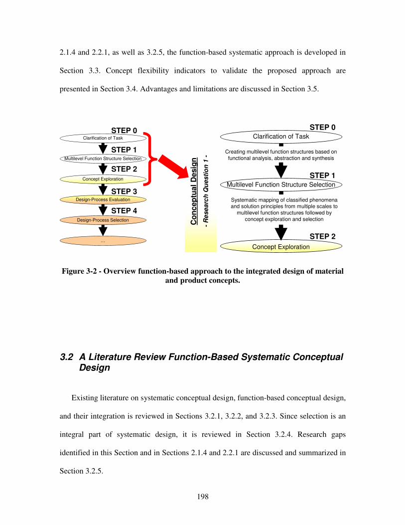
198
2.1.4 and 2.2.1, as well as 3.2.5, the function-based systematic approach is developed in
Section 3.3. Concept flexibility indicators to validate the proposed approach are
presented in Section 3.4. Advantages and limitations are discussed in Section 3.5.
Multilevel Function Structure Selection
Clarification of Task
Concept Exploration
Co
nc
ep
tual
Desig
n
-R
ese
arc
h Q
ues
tio
n 1
-
Creating multilevel function structures based on
functional analysis, abstraction and synthesisMultilevel Function Structure Selection
Clarification of Task
Design-Process Evaluation
…
Design-Process Selection
Concept Exploration
Systematic mapping of classified phenomena and solution principles from multiple scales to
multilevel function structures followed by
concept exploration and selection
STEP 3
STEP 0
STEP 1
STEP 2
STEP 4
STEP 0
STEP 1
STEP 2
Figure 3-2 - Overview function-based approach to the integrated design of material
and product concepts.
3.2 A Literature Review Function-Based Systematic Conceptual Design
Existing literature on systematic conceptual design, function-based conceptual design,
and their integration is reviewed in Sections 3.2.1, 3.2.2, and 3.2.3. Since selection is an
integral part of systematic design, it is reviewed in Section 3.2.4. Research gaps
identified in this Section and in Sections 2.1.4 and 2.2.1 are discussed and summarized in
Section 3.2.5.
199
3.2.1 Systematic Conceptual Design
As described in Section 1.1, conceptual design is perhaps the most demanding
activity in the product de sign process. Studies have shown that 80-90 % of the costs of a
product from manufacturing, maintenance and disposal are determined in the conceptual
design stage [731]. Poor decisions made at this stage cannot be compensated for in the
embodiment and detail design stage. Hence, especially in times of dynamic demands on
limited resources, design efforts should be focused on determining a satisficing concept,
i.e., “an idea that is sufficiently developed to evaluate the physical principles that govern
its behavior” [678].
Conceptual design is widely associated with intuition, i.e., generating a satisficing
concepts through ideation techniques, as reviewed in Section 2.2.2, and relying on
coming up with the right idea at the right time. Hence, research efforts in conceptual
design have also concentrated on developing intuitive geometric modeling tools such as
computer aided sketching tools. These efforts are not reviewed in this work. The reader is
referred to Hsu and Woon [276] for a review of geometric modeling in conceptual design
and Lipson and Shpitalni [375], Horváth and Rusák [273], Qin et al. [519], or Zeng et al.
[763] for more recent efforts. In this work, efforts are focused on systematic, problem-
oriented approach to conceptual design.
Systematic design is based on discursive and intuitive thinking. However, the key to
systematic design is discursive thinking – a conscious process that can be communicated
and influenced, in which scientific knowledge and relationships are consciously analyzed,
varied, combined in new ways, checked, rejected, and considered further [470]. As
illustrated in Figure 3-3, discursive thinking involves successive steps of information
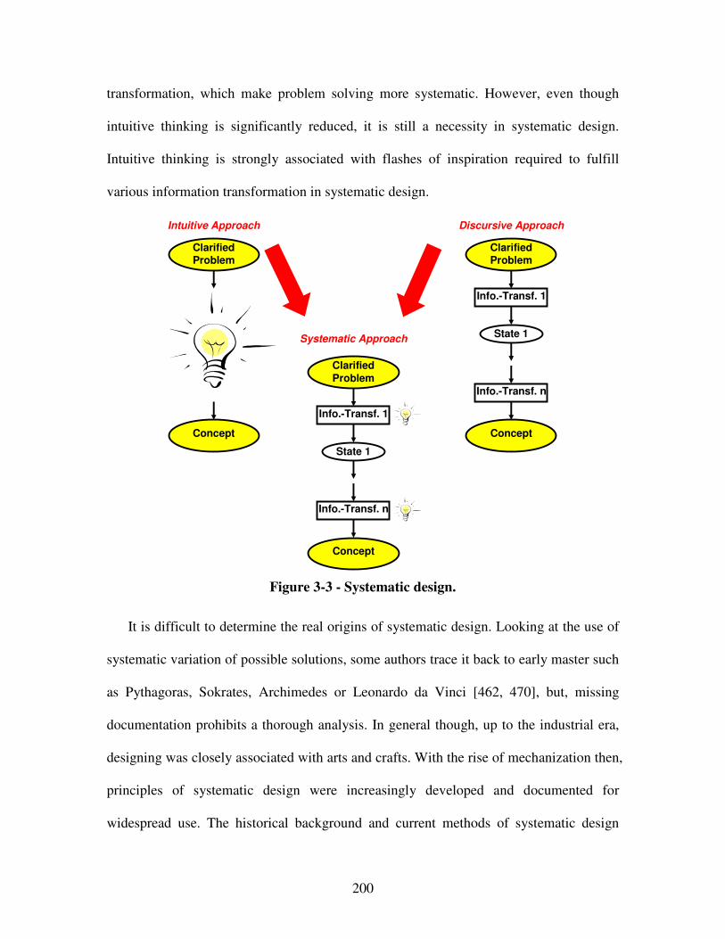
200
transformation, which make problem solving more systematic. However, even though
intuitive thinking is significantly reduced, it is still a necessity in systematic design.
Intuitive thinking is strongly associated with flashes of inspiration required to fulfill
various information transformation in systematic design.
ClarifiedProblem
ClarifiedProblem
Concept
Concept
Info.-Transf. 1
Info.-Transf. n
State 1
ClarifiedProblem
Concept
Info.-Transf. 1
Info.-Transf. n
State 1
Intuitive Approach Discursive Approach
Systematic Approach
Figure 3-3 - Systematic design.
It is difficult to determine the real origins of systematic design. Looking at the use of
systematic variation of possible solutions, some authors trace it back to early master such
as Pythagoras, Sokrates, Archimedes or Leonardo da Vinci [462, 470], but, missing
documentation prohibits a thorough analysis. In general though, up to the industrial era,
designing was closely associated with arts and crafts. With the rise of mechanization then,
principles of systematic design were increasingly developed and documented for
widespread use. The historical background and current methods of systematic design
201
methodologies are reviewed and summarized by Pahl and Beitz [470]. However,
Redtenbacher and Reuleaux pioneered some of the earliest ideas on the principles of
systematic design in the 1850s. The first step-by-step approach was developed Erkens in
the 1920s. The concept of systematic design was stimulated in the 1950s and 1960s by
Kesselring, Tschochner, Niemann, Matousek and Leyer – identifying the various phases
and steps of the design process, and providing specific recommendations and guidelines
for tackling them [699].
The advantages of systematic design in the conceptual stage, such as encouraging a
problem directed approach, fostering inventiveness, guiding the abilities of designers,
serving as a basis for communication and distributed design, etc., are crucial for problem
solving. In this context, a problem represents obstacles that prevent a transformation from
the undesirable initial state to the desirable goal state. A problem is characterized by
complexity and uncertainty, it is open-ended. On the contrary, a task imposes mental
requirements for which various means and methods are available to assist. However, it
has been shown that a systematic approach to design, involving strategically and
tactically ordered successive steps of information transformations, supports designers to
solve problems more efficiently and effectively than others [470].
A deliberate and systematic step-by step procedure ensures that nothing essential has
been overlooked or ignored and is therefore indispensable especially for conceptual
design since the correction of mistakes during the final steps of the product creation
process is extremely expensive and sometimes impossible. Also, systematic approaches
are often able to proactively help through the suggestion of solution principles or initial
concepts based on design catalogs as reviewed in Chapter 6. Furthermore, since
202
systematic approaches involve strategically and tactically ordered successive steps of
information transformations, they are also more susceptible for the development of
computing tools for concept generation. However, any systematic approach involves a
certain measure of intuition and expertise. The creative process cannot be logically
guaranteed, but, methodically encouraged. Therefore, systematic design does not replace
intrinsic creative skill of mankind but lifts human abilities to have ideas to a higher plan
by guiding attention in the right direction. The main advantage of the systematic
approach then is that designers do not have to rely on coming up with a good idea at the
right moment. Solution finding steps are documented and can always be revisited and
augmented to satisfy dynamic demands. However, within a systematic approach,
solutions can be elaborated using several existing relevant methods, such as information
gathering, analysis of natural or existing technical systems, analogies, brainstorming,
synectics, classification schemes, mathematical combination, etc.
A problem facing systematic approaches is the frequently heard argument that such
approaches run counter to the traditional way designers think, which is more
opportunistic focusing on elaborating an initial idea. These arguments appear to be based
on the view that systematic approaches are actual descriptions of the design activity [699].
However, systematic approaches are not intended to describe what happens, but to
propose new and better ways of working and hence represent methodologies. However,
especially systematic conceptual approaches differ substantially from product-oriented
approaches, in which the concept generation focuses on the analysis of an initial product
idea, which is then transformed into a concrete concept by step-wise refinement. In
product-oriented approaches, the generation of the concept is hardly supported, other than
203
by means of generic idea generation methods. The product-oriented approach is thus
intuitive with respect to the generation of concepts, but discursive with respect to the
analysis of solutions.
On the contrary, systematic conceptual approaches are problem-oriented, i.e., the
process of concept generation focuses on analysis of the problem and abstraction, rather
than on the analysis and evaluation of an initial product idea. Thus, concept generation
becomes a discursive process for which specific steps have been suggested to translate
the problem into a concept through a step-wise concretization involving various levels of
abstraction, e.g. functions, physical effects, working interrelationships, etc. In most
problem-oriented approaches, there is no explicit reference to the product idea resulting
from the initial product planning or clarification phase. This might lead to many
objections, suggesting the approaches are rigid and counter-intuitive. In product-oriented
approaches it is this initial product idea that is continually elaborated throughout the
design process. In this respect, product-oriented approaches are closer to general
engineering practice, but, also prone to solution fixation. Hence, the focus in this work is
on systematic problem-oriented conceptual design approaches.
3.2.2 Function-Based Design
Having clarified a given design problem, the first step in most design-processes is to
decompose the overall problem into easier to solve sub-problems. Several approaches
have been adopted in the decomposition of a design problem. However, systematic
204
conceptual design has traditionally been linked to representing designs and engineering
systems in terms of the functions they must fulfill. Hence, one of the main approaches
adopted is the use of the functional decomposition, i.e., a function-based approach. The
basic idea is that parts of any complex system will perform particular subfunctions that
contribute to an overall function. This involves functional decoupling of a coupled
system without concern for a possible physical implementation. However, this strategy is
sound since it forces the designer to get the ideal device behavior right first and helps to
focus both human and computer problem solving.
Several prescriptive models of the conceptual design process state that key is the
establishment of functional interrelationships. For example, Pahl and Beitz [470] point
out that establishing functional interrelationships facilitates the discovery of solutions
because it simplifies the general search for them and also because solutions to individual
functions can be elaborated separately. Suh [642] also states that the design procedure
involves interlinking the functional domain with the physical domain at every
hierarchical level of the design process. Ulrich and Eppinger [681] briefly describe two
other approaches for design problem decomposition, decomposition by sequence of user
actions and decomposition by key customer needs. Ahmed and Wallace [14] describe
another approach to decompose design problems based on issues.
As noted by Simon [596], discovering viable ways of decomposing a complex system
into semi-independent parts corresponding to the system’s many functional parts is a
powerful and well respected technique. The key is that the design of each part can be
carried out with some degree of independence, since each part will affect other parts
largely through its function and independently of the details of the mechanisms that
205
accomplish the function. Hence, a broader solution field can be generated and designers
are less likely to be constrained by existing solutions. Therefore, this work is focused on
the use of functional decomposition of the design problem.
Although the concept of function has been widely used in design and other disciplines,
it has no clear and widely accepted definition [686]. Pahl and Beitz [470] defined the
term function as the general input/output relationship of a system whose purpose is to
perform a task. The function is an abstract formulation of the task. The input and output
flows across system boundaries are energy, material or signals. Ullman [679] presents a
similar definition of a function as “the logical flow of energy, material and information
between objects or the change of state of an object caused by one or more of the flows”.
Both these definitions take the view that function involves a certain transformation from
a flow into a system and a flow out of a system.
Umeda and Tomiyama [686] argue that such a definition can not represent a function
that does not involve a transformation. For this reason, several researchers have proposed
other definitions of function. Chittaro and Kumar [126] define a function in two ways,
operational and purposive. Operational refers to the relation between the input and output
of energy, material or information in a component. Purposive refers to the relation
between the goal of a user and the behavior of the component. Chakrabarti [98] also
proposes two views of a function, one that is at the same level of abstraction as behavior
and one at a higher level that serves a purpose. Deng [156] argues that a function is not
either operational or purposive, but both. The purpose aspect refers to the designer’s
intent and the operational aspect, that Deng [156] refers to as an action, is the intended
and useful behavior exhibited by an artifact.
206
Differences in the definition of a function can be attributed to the differences in the
scope and domain in which work has been carried out and the purpose for which the
definition is meant for. The differences in definition have resulted in different ways of
representing function. Two main approaches for representing functions have been
identified [46, 99, 651], a representation based on input and output of flow [46, 587, 653]
and a representation based on natural language using verbs to represent what the function
does [326, 636]. Due to the expressiveness of natural language, a wider range of
functions could be represented regardless of whether it is a general purpose or an action.
But, for the same reason that natural language is expressive, it is difficult to arrive at a
formal taxonomy.
Several functional modeling systems aid a user in defining system functions to be
achieved during conceptual design. For example, Johnson [304] develop an early
functional modeling system. Functional verbs were used to describe the functional
interactions between sub-assemblies, components, features, working fluids and the
environment. A standard vocabulary was also developed for components and features.
Through the Design Repository Project at the NIST [652, 655] a web-based system for
functional modeling has been developed. Deng et al. [157] present a functional modeling
design environment based on a dual step functional modeling strategy, an initial
functional decomposition step, exploring functionally independent sub-design tasks,
followed by a causal behavioral process generation step, exploring the relationships
between the sub-design tasks. Anthony et al. [24] have presented the development of a
system called Conceptual Understanding and Prototyping (CUP) for the capturing the
structure, behavior and function of artifacts. Vergas-Hernandez and Shah [692] have
207
developed a tool for conceptual design supporting functional modeling, behavior
modeling and component selection from standard catalogs.
Several other function-based modeling techniques exist, such as the Function-
Behavior-Structure framework by Qian and Gero [229, 518], the Function-Behavior-State
framework by Umeda and Tomiyama [685, 686], and the Function-Environment-
Behavior-Structure framework by Deng and coauthors [155]. In the Function-Behavior-
Structure framework for example, design is represented as a process in which a
representation of a design objective, which includes function, is gradually refined. Each
function evolution involves functional realization (i.e., converting a function into
structure), functional evaluation (i.e., confirming functional description with behavior)
and functional operation (i.e., adding functional elements and function relations to
functional description). Also, research work carried out in synthesizing dynamic systems
focuses on the use of bond graph methods, as described in [728]. However, to
accommodate materials domain expertise and the use of functional representations in the
science-based materials domain, the expressiveness of natural language is leveraged.
Also, automated functional synthesis approaches are not addressed in this work. For
example, Finger and Rinderle [208] propose a software that uses transformational
grammar and bond graph representations for changing functions or an existing design
into new designs realizing the same functions. This is one of the earliest papers in which
grammars are used for generating designs – a precursor to much work on various
generative grammar-based approaches. Formal grammars that can generate and parse
valid strings in a language have proven useful in a number of fields besides engineering
design, most notably linguistics [134, 633] computer science [180, 443] and architecture
208
[171, 211, 335, 634]. In engineering design, various grammar-based approaches, mainly
used to transform abstract representations of function to less abstract representations of
form through a vocabulary of valid symbols and rules, have been developed by
Heisserman and Woodbury [260], Pinilla et al. [504], Shea and Cagan [588], Schmidt and
Cagan [570], and Heisserman [261] among others.
Another focal area of function-based synthesis is agent-based methods, as described
in the literature [89, 90, 728]. For example, based on the functional specification,
concepts are generated by using elements, such as generic springs, gears, etc., and agents
coded with operations to combine these elements (in analogy of basic artificial life
elements that are coded with certain reflexive operations) according to the demands
stated in the in functional parameters. Other examples of automated synthesis approaches
are the use of evolutionary and adaptive synthesis methods – as reviewed by Lee et al.
[362] – or genetic programming – an extension of the genetic algorithm [270] in which
the population being bred consist of computer programs [339-341]. However, automated
functional synthesis approaches are not addressed in this work but should be addressed in
future work, as described in Section 9.4.
Generally, in the design literature, functional relationships are used to describe the
intended effect, i.e., the functionally desired effect in the sense of system operation. On
the contrary, behavioral relationships are used to describe functionally undesired and
unintended effects of a technical system (e.g., side, disturbing, feedback or coupling
effects that become apparent upon system modeling or realization). One approach to
represent behavior is the transformation of an input flow to an output flow as discussed in
the definition and representation of a function. However, the transformation from an

209
input and to an output could also be represented using bond graphs [73]. Iwaskai et al.
[300] presented another approach called the Causal Functional Representational
Language (CFRL), a language for function and behavior representation representing the
behavior as a Boolean combination of causal process descriptions. Since modeling and
simulation of behavior often contains constraints, Deng et al. [158] and O’Sullivan [456]
propose constrained based approaches in behavior analysis. However, the interested
reader is referred to the literature. Behavioral relationships are not addressed in this work.
Having reviewed the literature on function-based design and modeling, functional
decomposition on multiple levels and scales is adopted as a key foundation to the
proposed approach to systematic integrated design of product and material concepts.
Hence, the term function is applied to the overall input/output relationship of the
integrated material and product system by reference to purpose. Philosophically [719],
energy, matter and information are adapted as basic concepts of system inputs and
outputs crossing a system boundary. However, in the design literature, as adopted in this
work, this terminology is usually linked to concrete physical or technical representations,
e.g., energy is often specified by its manifest form, matter is usually substituted by
material with specific properties, and the general concept of information is given a more
concrete expression by means of the term signal – the physical form in which the
information is conveyed [470].
In this work functions are represented based on solution-neutral natural language by
combining the nouns energy, material and signal with a respective verb while taking into
account in- and output flows, as described in detail in Section 3.3.1. Due to the
expressiveness of natural language, a wider range of functions can be represented which

210
is crucial to accommodate the use of functional representations in the materials domain.
As a result, function-based design may be subjective, but not arbitrary or ad-hoc – overall,
it is used to describe a designer’s preferences under ideal circumstance in a solution-
neutral way. Also, a common vocabulary that is well-suited for function-based design on
the materials level is proposed in Section 3.3.1 to extend existing taxonomies [652, 655].
In summary, advantages of function-based approaches are that i) domain-independent
solution finding is facilitated, ii) a broader solution field can be generated, iii) a designer
is encouraged to abstract essential problem characteristics, iv) designers are less likely to
be constrained by existing solutions and focus on known solutions, v) non-intuitive
solutions are easier to identify, vi) systematic design space expansion and exploration is
supported, vii) a foundation for modular and reconfigurable design is provided, viii)
planning and managing design is facilitated, as well as ix) the approach itself is practical,
easy to use for designers in any domain and interfaces well with various systems design
methods. Also, evidence from practice shows that more innovative solutions frequently
emerge from function-based systematic approaches and the logic underpinning these
solutions is more clearly understood [470]. However, shortcomings of most function-
based approaches are that they do not provide systematic mappings to obtain concepts
based on functional representations, as discussed in the following section.
211
3.2.3 Function-Based Systematic Conceptual Design
It is not possible to mention every researcher, but key contributions to function-based
systematic design were made by Hansen [249], Rodenacker [547], Roth [552], Koller
[332], Ehrenspiel [179] and Pahl and Beitz [470]. In an attempt to unify the diversity of
existing function-based systematic design approaches and perspectives – such as the ones
by Roth [552], Rodenacker [547], Koller [332] or Pahl and Beitz [470] – a generic
approach to the function-based systematic design of technical systems and products,
emphasizing the general applicability in the fields of mechanical, precision, control,
software and process engineering, has been proposed by an “Association of German
Engineers” committee (VDI guidelines 2221 and 2222). One of the most well known
function-based systematic design methodologies however is the one proposed by Pahl
and Beitz for the mechanical engineering domain.
Pahl and Beitz propose a function-based systematic planning and design process for
mechanical engineering (with reference to VDI Guidelines 2221 and 2222), based on best
practices from industry [470]. Their systematic design methodology is essentially based
on the fundamentals of technical systems, the fundamentals of the systematic approach
and the general problem-solving process. The aim is to adapt the general statements to
the requirements of the mechanical engineering design-process and to incorporate the
specific working and decision making steps for this domain. In principle the planning and
design process proceeds from the planning and clarification of the task, through the
identification of the required functions, the systematic elaboration of principal solutions,
the construction of modular structures, to the detailed documentation of the complete
product. Pahl and Beitz divide the planning and design process into four main phases and
212
propose main working steps for each of these phases as described in great detail in [470]
and illustrated in Figure 1-4.
The conceptual function-based systematic approach proposed in this work is strongly
related to the working steps in the conceptual design phase of the Pahl and Beitz design
process. In the Pahl and Beitz design-process, having clarified the problem and
documented system requirements in a solution neutral form, analysis is conducted first.
Via abstraction, the crux of the problem is then identified. Iteratively analyzing,
abstracting and synthesizing, system and subsystem level function structures are
developed. Individual sub-functions are then replaced with working principles. Working
principles can be described quantitatively by means of the physical laws governing the
physical quantities involved. According to Pahl and Beitz [470], a functional relationship
realized by the selected working principles and the determined working characteristics,
i.e., movement, surface, etc. actively engaged in realizing the function being embodied,
results in a working interrelationship. This working interrelationship fulfils the function
in accordance with the task.
Several working principles may have to be combined in order to fulfill a function.
However, a function can often be fulfilled by one of a number of working principles.
Having identified, selected and combined working principles, a principal solution may
emerge. An emerging principal solution is then further refined. This then is the first
concrete step in the implementation of the solution. In the mechanical engineering
domain for example, “transferring the torque by friction against a cylindrical working
surface in accordance with Colulomb’s law will, depending on the way in which the
normal force is applied, lead to the selection of a shrink fit or a clamp connection as the
213
working principle” [470]. It is through the subsequent combination of working
interrelationships of the various sub-functions into working structures that the solution
principle for fulfilling the overall tasks can be recognized, representing how the solution
will work at the fundamental principle level.
Often, the principal solution achieved will not be concrete enough to evaluate the
solution principle. It may need to be quantified, for example by rough scale drawings or
calculations, before the solution principle can be evaluated. The result however is called a
concept. A concept is the starting point for further concretization in the embodiment and
detail design phases, taking into account the needs of later product life cycle phases.
However, in summary the steps to generate a concept based on a clarified solution-neutral
problem statement within the conceptual phase of the Pahl and Beitz design process
include:
• Abstraction to identify essential problems,
• Generation of system function structures,
• Search for working interrelationships, e.g., working-principle, -movement, -
surface, -direction, etc., actively engaged in realizing a function being embodied,
• Combination of working interrelationships into working structures,
• Selection of suitable combinations,
• Refinement into principal solution variants, and
• Evaluation against technical and economic criteria to determine a system concept.
Having reviewed systematic design approaches, it is noted that any systematic design
method consists of one or several of the following general methods: analysis, abstraction,
synthesis, method of persistent questions, method of negation, method of forward steps,
214
methods of backward steps, method of factorization, method of systematic variation,
division of labor and collaboration [470]. From these general methods, functional
decomposition, analysis, abstraction, synthesis and systematic variation are leveraged as
core transformations for the function-based systematic approach presented in this work.
3.2.4 A Note On Selection
A number of decision making methods and tools have been developed to aid in the
selection of one or more concepts to be refined in the embodiment and detailed design
phase. Selection of several concepts reduces the risk involved in committing to a single
design. Set-based design, as reviewed in Section 2.2.3 and initially employed at Toyota,
is an example in which several concepts are chosen to be refined during embodiment and
detail design [679]. However, even if more than one concept is chosen, decision making
methods and tools are still required to aid a designer in decision making. Since selection
is an integral part of almost every step in design and many researchers have devoted their
work to selection, selection of design alternatives is not a primary research focus in this
work. The focus in this work is on generating system concepts. However, it is
emphasized that concept evaluation and selection is an integral part of design, especially
in the early stages.
Evaluation of concepts involves determining its feasibility and realizabilty. Besides
systematic analysis, two main approaches have been adopted, namely i) using checklists
or ii) guidelines, as for example presented by Pahl and Beitz [470], Mukherjee and Liu
215
[439], or Huang et al. [280]. Having evaluated feasibility and realizability of concepts,
various attention-directing selection approaches have been proposed. For example, Pugh
[516] has suggested the use of a matrix that compares alternative solutions against criteria
that have been identified as being significant. In his approach, a datum is chosen with
which all other concepts are to be compared based on the criteria set forth, resulting in a
pattern that differentiates the better concepts. Alternatively, Pahl and Betiz [470] have
presented an approach to evaluate solutions based on the ‘use-value’ analysis method.
Each solution is given a value (expressed as points) relating to a weighted evaluating
criterion to determine better concepts.
Other approaches utilized in selecting concepts are more mathematically rigorous
approaches, such as multi attribute utility theory (Von Neumann and Morgenstern [697],
Keeney and Raiffa [319]). In multi attribute utility theory, an expected utility is
determined for each alternative which defines a designer’s preference for that alternative
under uncertainty and risk. In conceptual design, Thurston [668] has applied utility
analysis to compare preliminary alternatives to identify the best available combination of
attribute levels. Malak and coauthors have developed means for systematic selection
using multi-attribute utility analysis [386] and parameterized Pareto sets to model design
concepts [388]. An alternative to the use of utility theory in relating preferences in
concept selection is the use of fuzzy set theory. Wang [705] used fuzzy logic to rank
concepts by describing the performance of each criterion for an alternative as a linguistic
term related to a fuzzy set. Another approach used in deciding on concepts to be selected
is the Analytical Hierarchy Process proposed by Saaty [556] and exemplified in Chen and
Lin [103].
216
As the function-based systematic approach developed in this work is for conceptual
design, information on the concepts generated is limited to the configuration of the
functional interrelationships, embodying phenomena and associated solution principles,
as well as rough sketches of the parts and initial thoughts on realizability (such as
manufacturing processes, assembly operations, resistance against environmental effects,
etc.). Feasibility of mathematical rigorous concept selection approaches is thus limited
due the inherent lack of concrete information at these early stages of design before
detailed analysis is carried out and the need to process both, quantitative and qualitative
information based on a designer’s subjective (not arbitrary) judgment. For example, as
argued by Simon [595], use of the subjective expected utility model is based on the
assumption that the decision maker contemplates, in one comprehensive view, everything
that lies before him. When operating at the level of phenomena and solution principles,
such a model is clearly not appropriate.
Also, a meaningful cost analysis, as for example reviewed by Pahl and Beitz (1996),
Asiedu and Gu (1998) or Layer et al (2002), is restricted to evaluating the cost of raw
materials once those are being selected. Estimating life cycle cost associated with a
conceptual design, referring to the costs incurred in the design, production, support and
disposal of a product however, becomes only meaningful once more detailed analysis has
been conducted during the detail design phase. Hence, concept evaluation and selection
in this work is focused on concept performance, and associated concept functionality and
realizability indicators, while considering uncertainty in preference and attribute ratings,
based on selection Decision Support Problem (sDSP) implemented in the software
217
DSIDES, reviewed in Section 2.1.1. In DSIDES, uncertainty in preference and attribute
ratings is accounted for through exact interval arithmetic.
The lack of concrete information at these early stages of design is acknowledged.
Hence, not one, but multiple most promising concepts are further explored through
partially and fully instantiated template-based compromise Decision Support Problems
(cDSPs) [433], reviewed in Chapter 2.1.1, before selection is narrowed down to a single
concept.
3.2.5 Research Gap Analysis
So far, focus of any function-based systematic design methodology has been on
mechanical engineering domain-specific applications, such as connections, guides and
bearings, power generation and transmission, kinematics, gearboxes, safety technology,
ergonomics as well as production processes. As described in Section 1.1, function-based
systematic approaches are based on material selection during the embodiment design
phase, after product concepts have already been designed. As stated in Section 2.1.2 and
summarized in Table 2-3, integrated materials and product design efforts involving
phenomena and associated solution principles on the multiscale materials level to drive
concept generation from a systems perspective and increase concept flexibility have not
yet been addressed. Hence, a vast array of (potentially superior) solution principles is not
considered before resources are allocated to a specific concept, that is further embodied,
detailed, and realized during the subsequent product life cycle phases. Therefore,
218
enhancing existing function-based systematic design approaches by incorporating the
potential embedded in materials design to increase a designer’s concept flexibility is a
primary focus in this work.
As reviewed in Sections 2.1.1, 2.1.2 and 2.1.3 and summarized in Tables 2.2, 2.3 and
4, systematic conceptual materials design has not yet been addressed or leveraged for the
design of engineering systems. However, only relying on a designer’s or design team’s
personal experiences during concept generation may result in the exclusion of a vast
array of feasible concepts [374]. Current materials design approaches do not address the
conceptual design phase – the most crucial design stage in which decisions allocate the
vast majority of a product’s resources – in a systematic fashion. Besides the development
of advanced methodologies for material selection [27, 28], a paradigm shift towards
materials design with the objective of tailoring the chemical composition, constituent
phases, microstructure and processing paths to obtain materials with desired properties
for particular applications has begun [129, 413, 459, 475, 579, 581]. So far, however,
materials design has mostly been exercised in the embodiment phase focusing on
multiscale modeling techniques developed recently [53, 129, 475]. A detailed review of
materials design is presented in Section 2.1.3.
In order to not limit materials design to detail or embodiment design emphasizing
multiscale analysis rather than synthesis as seen in the literature today, a function-based
systematic approach to conceptual materials design is proposed in this work. Limitations
of existing product and materials design approaches are summarized in Table 1-5.
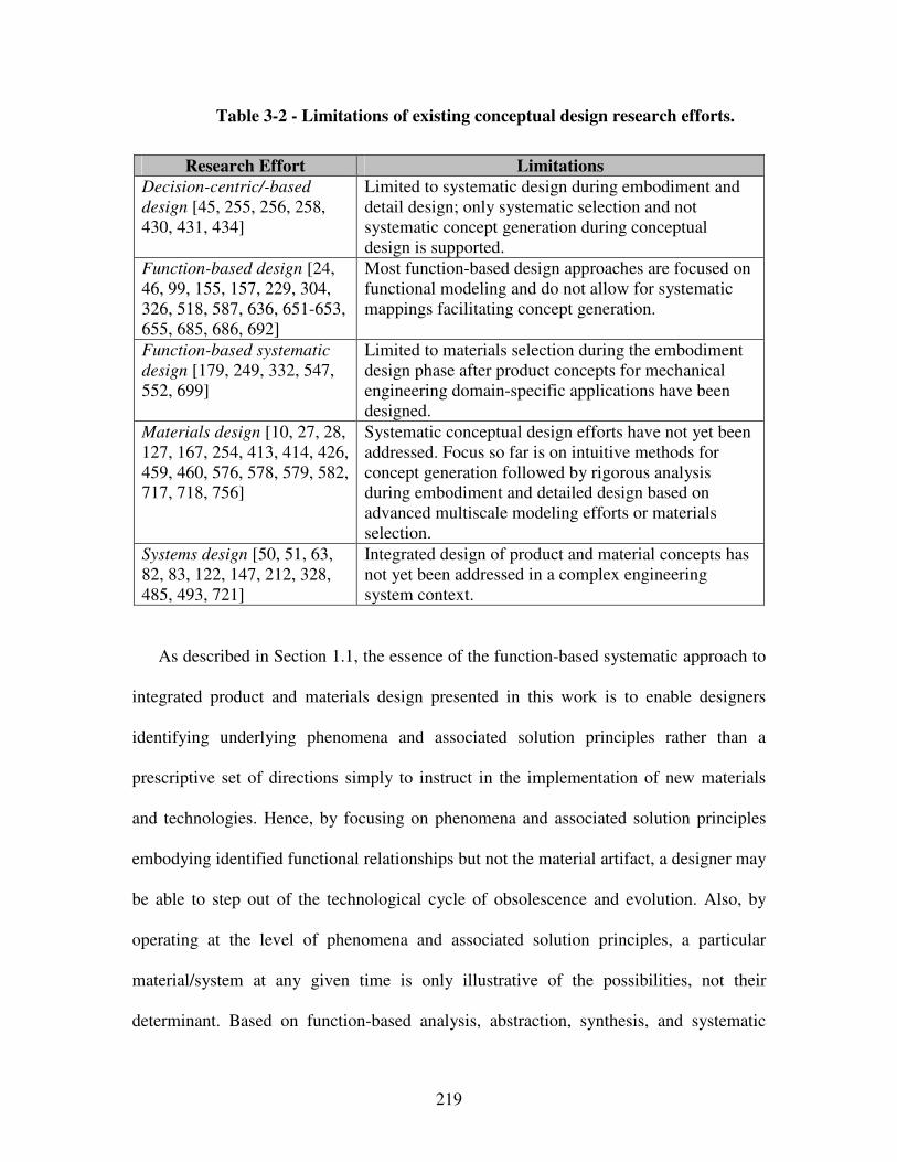
219
Table 3-2 - Limitations of existing conceptual design research efforts.
Research Effort Limitations
Decision-centric/-based
design [45, 255, 256, 258, 430, 431, 434]
Limited to systematic design during embodiment and detail design; only systematic selection and not systematic concept generation during conceptual design is supported.
Function-based design [24, 46, 99, 155, 157, 229, 304, 326, 518, 587, 636, 651-653, 655, 685, 686, 692]
Most function-based design approaches are focused on functional modeling and do not allow for systematic mappings facilitating concept generation.
Function-based systematic
design [179, 249, 332, 547, 552, 699]
Limited to materials selection during the embodiment design phase after product concepts for mechanical engineering domain-specific applications have been designed.
Materials design [10, 27, 28, 127, 167, 254, 413, 414, 426, 459, 460, 576, 578, 579, 582, 717, 718, 756]
Systematic conceptual design efforts have not yet been addressed. Focus so far is on intuitive methods for concept generation followed by rigorous analysis during embodiment and detailed design based on advanced multiscale modeling efforts or materials selection.
Systems design [50, 51, 63, 82, 83, 122, 147, 212, 328, 485, 493, 721]
Integrated design of product and material concepts has not yet been addressed in a complex engineering system context.
As described in Section 1.1, the essence of the function-based systematic approach to
integrated product and materials design presented in this work is to enable designers
identifying underlying phenomena and associated solution principles rather than a
prescriptive set of directions simply to instruct in the implementation of new materials
and technologies. Hence, by focusing on phenomena and associated solution principles
embodying identified functional relationships but not the material artifact, a designer may
be able to step out of the technological cycle of obsolescence and evolution. Also, by
operating at the level of phenomena and associated solution principles, a particular
material/system at any given time is only illustrative of the possibilities, not their
determinant. Based on function-based analysis, abstraction, synthesis, and systematic
220
variation, as well as systematic mappings of phenomena and associated solution
principles from multiple disciplines to multilevel function structures, the function-based
systematic approach to integrated product and materials design is developed in the
following section.
An overview of the systematic function-based approach to the integrated design of
product and material concepts and their subsequent exploration and selection based on
template-based selection and compromise DSP formulations is illustrated in Figure 3-4.
In Section 3.3, functional decomposition, systematic mappings and concept selection
charts are described as key elements of this systematic approach. Then, measure of
success, i.e., concept flexibility indicators are defined in Section 3.4. Limitations and
opportunities for future work are discussed in Section 3.5 along with verification and
validation in Section 3.6. The systematic approach described in this section is tested with
the reactive containment system example problem in Chapter 7.
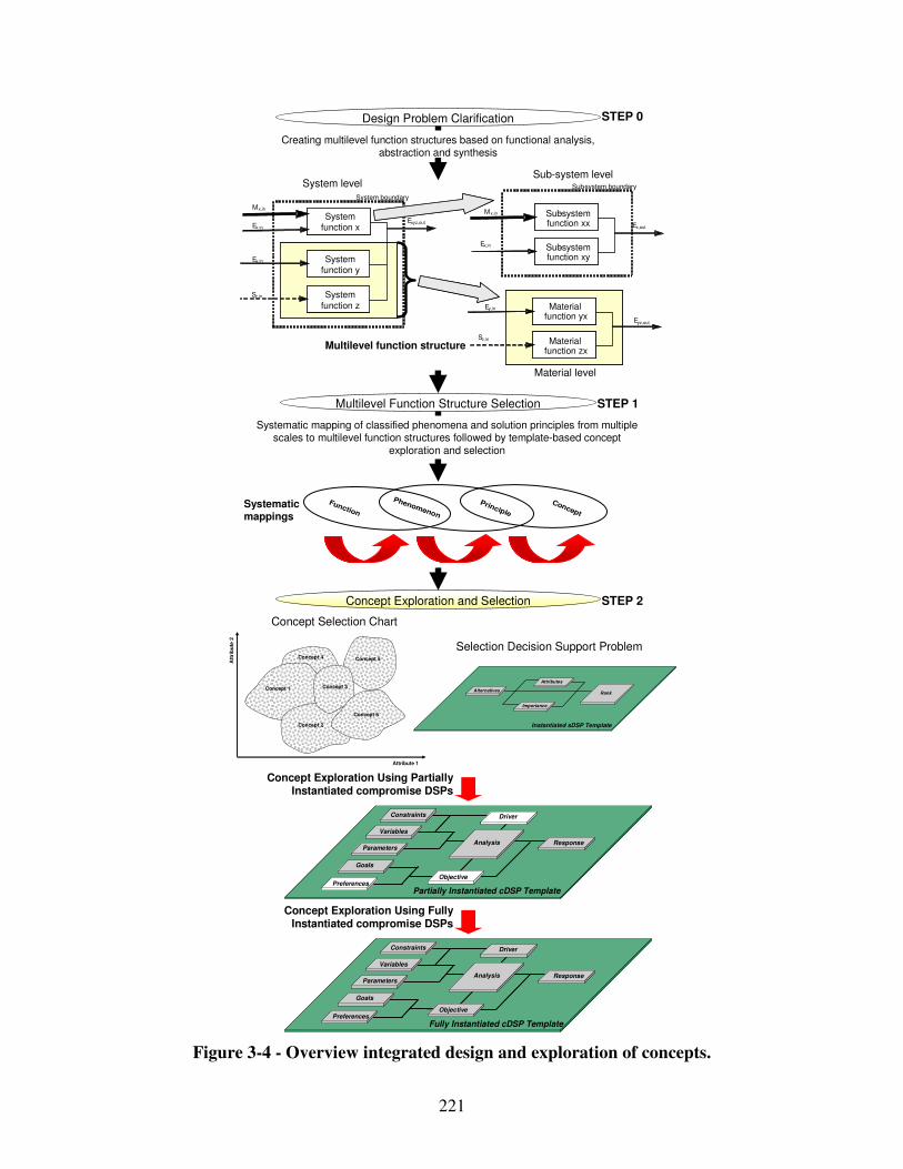
221
Systematic mapping of classified phenomena and solution principles from multiple scales to multilevel function structures followed by template-based concept
exploration and selection
Creating multilevel function structures based on functional analysis, abstraction and synthesis
Ex,in
Mx,in
Ex,in
System boundary
System function x
Exyz,out
System
function z
System function y
Ey,in
Sz,in
Mx,in Sub-system function xx Ex,out
Sub-system function xy
Sz,in
Ey,in Material function yx
Eyz,out
Material function zx
Sub-system boundarySystem levelSub-system level
Material level
Design Problem Clarification
Multilevel Function Structure Selection
Concept Exploration and Selection
Concept
Principle
Phenomenon
Function
STEP 0
STEP 1
STEP 2
Systematic mappings
Multilevel function structure
Att
rib
ute
2
Attribute 1
Concept 2
Concept 5
Concept 1 Concept 3
Concept 6
Concept 4
Selection Decision Support Problem
Concept Selection Chart
AlternativesRank
Instantiated sDSP Template
Importance
Attributes
Concept Exploration Using Partially
Instantiated compromise DSPs
Concept Exploration Using Fully Instantiated compromise DSPs
Goals
Preferences
Variables
Parameters
Constraints
Response
Objective
Analysis
Driver
Fully Instantiated cDSP Template
Goals
Preferences
Variables
Parameters
Constraints
Response
Objective
Analysis
Driver
Partially Instantiated cDSP Template
Figure 3-4 - Overview integrated design and exploration of concepts.
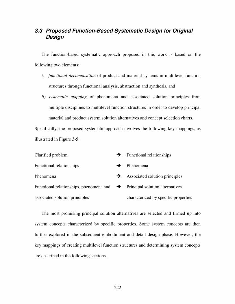
222
3.3 Proposed Function-Based Systematic Design for Original Design
The function-based systematic approach proposed in this work is based on the
following two elements:
i) functional decomposition of product and material systems in multilevel function
structures through functional analysis, abstraction and synthesis, and
ii) systematic mapping of phenomena and associated solution principles from
multiple disciplines to multilevel function structures in order to develop principal
material and product system solution alternatives and concept selection charts.
Specifically, the proposed systematic approach involves the following key mappings, as
illustrated in Figure 3-5:
Clarified problem � Functional relationships
Functional relationships � Phenomena
Phenomena � Associated solution principles
Functional relationships, phenomena and
associated solution principles
� Principal solution alternatives
characterized by specific properties
The most promising principal solution alternatives are selected and firmed up into
system concepts characterized by specific properties. Some system concepts are then
further explored in the subsequent embodiment and detail design phase. However, the
key mappings of creating multilevel function structures and determining system concepts
are described in the following sections.
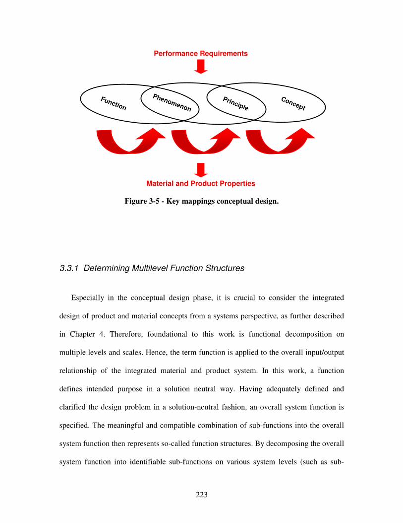
223
Figure 3-5 - Key mappings conceptual design.
3.3.1 Determining Multilevel Function Structures
Especially in the conceptual design phase, it is crucial to consider the integrated
design of product and material concepts from a systems perspective, as further described
in Chapter 4. Therefore, foundational to this work is functional decomposition on
multiple levels and scales. Hence, the term function is applied to the overall input/output
relationship of the integrated material and product system. In this work, a function
defines intended purpose in a solution neutral way. Having adequately defined and
clarified the design problem in a solution-neutral fashion, an overall system function is
specified. The meaningful and compatible combination of sub-functions into the overall
system function then represents so-called function structures. By decomposing the overall
system function into identifiable sub-functions on various system levels (such as sub-
Concept
Principle
Phenomenon
Function
Performance Requirements
Material and Product Properties
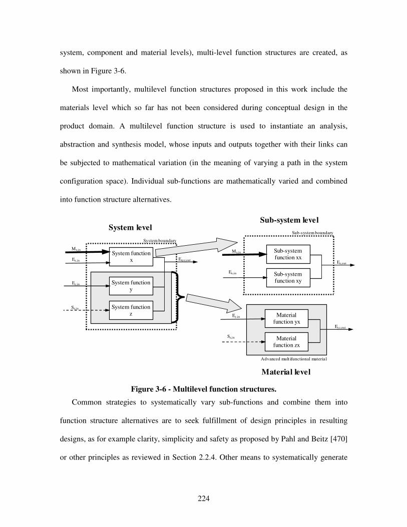
224
system, component and material levels), multi-level function structures are created, as
shown in Figure 3-6.
Most importantly, multilevel function structures proposed in this work include the
materials level which so far has not been considered during conceptual design in the
product domain. A multilevel function structure is used to instantiate an analysis,
abstraction and synthesis model, whose inputs and outputs together with their links can
be subjected to mathematical variation (in the meaning of varying a path in the system
configuration space). Individual sub-functions are mathematically varied and combined
into function structure alternatives.
Advanced mult ifunctional material
Ex,in
Mx,in
Ex,in
System boundary
System function x Exyz,out
System function z
System function y
Ey,in
Sz,in
Mx,in Sub-system function xx
Ex,out
Sub-system function xy
Sz,in
Ey,in Material function yx
Eyz,out
Material function zx
Sub-system boundary System level
Sub-system level
Material level
Figure 3-6 - Multilevel function structures.
Common strategies to systematically vary sub-functions and combine them into
function structure alternatives are to seek fulfillment of design principles in resulting
designs, as for example clarity, simplicity and safety as proposed by Pahl and Beitz [470]
or other principles as reviewed in Section 2.2.4. Other means to systematically generate
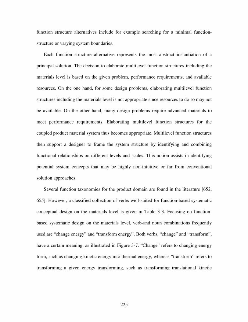
225
function structure alternatives include for example searching for a minimal function-
structure or varying system boundaries.
Each function structure alternative represents the most abstract instantiation of a
principal solution. The decision to elaborate multilevel function structures including the
materials level is based on the given problem, performance requirements, and available
resources. On the one hand, for some design problems, elaborating multilevel function
structures including the materials level is not appropriate since resources to do so may not
be available. On the other hand, many design problems require advanced materials to
meet performance requirements. Elaborating multilevel function structures for the
coupled product material system thus becomes appropriate. Multilevel function structures
then support a designer to frame the system structure by identifying and combining
functional relationships on different levels and scales. This notion assists in identifying
potential system concepts that may be highly non-intuitive or far from conventional
solution approaches.
Several function taxonomies for the product domain are found in the literature [652,
655]. However, a classified collection of verbs well-suited for function-based systematic
conceptual design on the materials level is given in Table 3-3. Focusing on function-
based systematic design on the materials level, verb-and noun combinations frequently
used are “change energy” and “transform energy”. Both verbs, “change” and “transform”,
have a certain meaning, as illustrated in Figure 3-7. “Change” refers to changing energy
form, such as changing kinetic energy into thermal energy, whereas “transform” refers to
transforming a given energy transforming, such as transforming translational kinetic
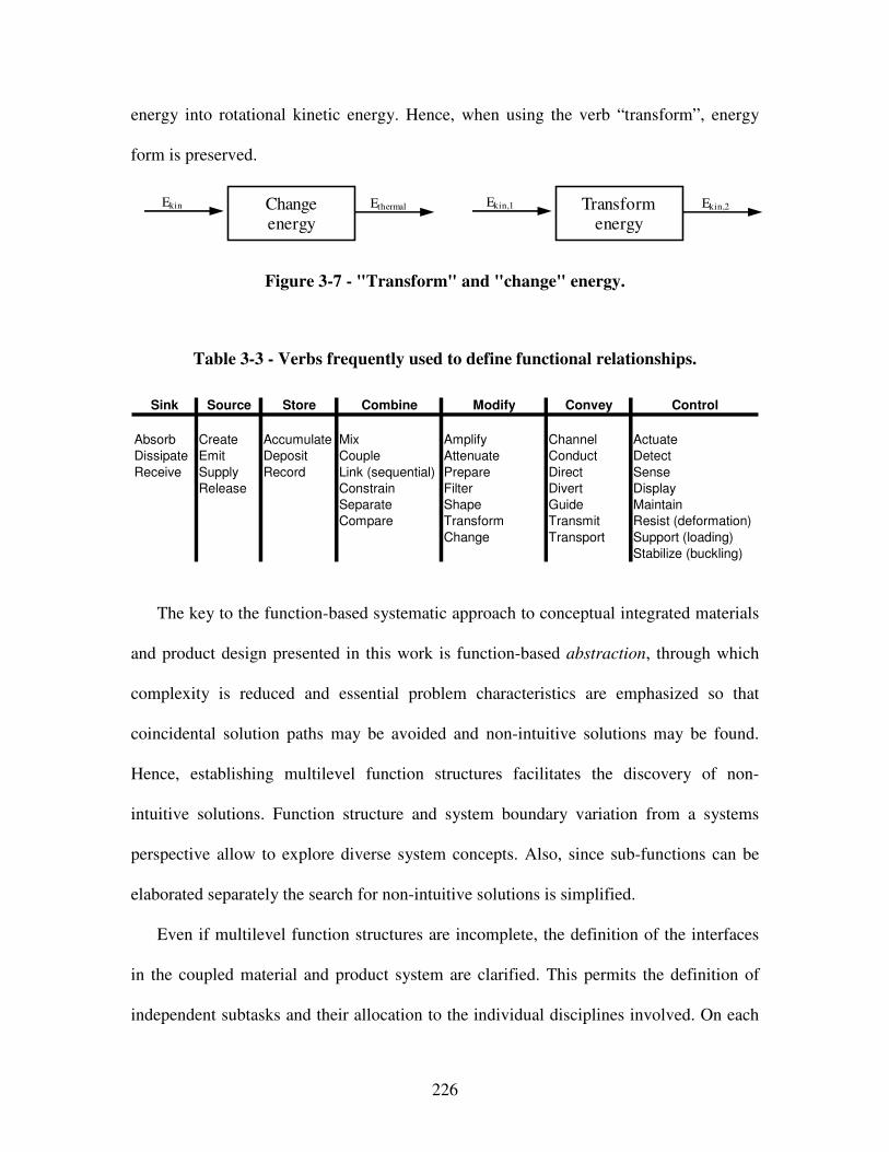
226
energy into rotational kinetic energy. Hence, when using the verb “transform”, energy
form is preserved.
Ekin Ethermal Change energy
Ekin,1 Ekin,2 Transform energy
Figure 3-7 - "Transform" and "change" energy.
Table 3-3 - Verbs frequently used to define functional relationships.
Sink Source Store Combine Modify Convey Control
Absorb Create Accumulate Mix Amplify Channel Actuate
Dissipate Emit Deposit Couple Attenuate Conduct Detect
Receive Supply Record Link (sequential) Prepare Direct Sense
Release Constrain Filter Divert Display
Separate Shape Guide Maintain
Compare Transform Transmit Resist (deformation)
Change Transport Support (loading)
Stabilize (buckling)
The key to the function-based systematic approach to conceptual integrated materials
and product design presented in this work is function-based abstraction, through which
complexity is reduced and essential problem characteristics are emphasized so that
coincidental solution paths may be avoided and non-intuitive solutions may be found.
Hence, establishing multilevel function structures facilitates the discovery of non-
intuitive solutions. Function structure and system boundary variation from a systems
perspective allow to explore diverse system concepts. Also, since sub-functions can be
elaborated separately the search for non-intuitive solutions is simplified.
Even if multilevel function structures are incomplete, the definition of the interfaces
in the coupled material and product system are clarified. This permits the definition of
independent subtasks and their allocation to the individual disciplines involved. On each
227
level, energy, matter and information are adapted as basic concepts of system inputs and
outputs crossing a system boundary. A function structure thus consists of linked
subfunctions representing the flow and conversions of energy, material, and signal. Sub-
functions can then be derived from conversions of energy, material, and signal.
Individual sub-functions, originally represented by “black-boxes” in the developed
function structures, must however be replaced with more concrete statements in
mathematical form to allow for simulation-based design in a distributed environment.
The mappings involved in determining and embodying principal solutions based on the
developed functional relationships are described in the following section.
3.3.2 Determining Concepts
Having developed functional relationships and combined them into multilevel
function structures through analysis, abstraction and synthesis, multiscale phenomena and
associated governing solution principles from multiple disciplines are systematically
mapped to specific functions. The most promising solution principles are mapped in
concept selection charts (as described in Section 3.3.3), combined in morphological
charts [470] and then varied to develop material and product system concepts. In order to
develop wide ranged principal solution alternatives, it is crucial to identify phenomena
and associated principles on multiple levels and scales from relevant disciplines.
Phenomena are described quantitatively by means of laws governing the quantities
involved. In other words, phenomena can be described by the laws of physics and
228
mathematics. For example, the operation of a bi-metallic strip is the result of a
combination of two phenomena, namely thermal expansion and elasticity. A sub-function
can often be fulfilled by one of a number of phenomena. For example, a force can be
amplified by the mechanical lever phenomenon, fluid-mechanical hydraulic lever
phenomenon, or electromagnetic phenomena. In the design literature, such phenomena
are also labeled physical effects, chemical effects, etc. These effects have therefore been
classified in terms of the discipline from which they are derived, such as mechanical
engineering. Physical effects for the specific domains of mechanical and electrical
engineering have already been classified by Koller [332], Clausen and Rodenacker [138]
as well as Roth [552]. A few chemical effects are summarized by Orloff [462]. Focus
however has so far been on mechanical engineering domain-specific applications, such as
connections, guides and bearings, power generation and transmission, kinematics,
gearboxes, safety technology, ergonomics as well as production processes.
Multidisciplinary integrated materials and product design efforts involving
phenomena and associated solution principles, in other words property-structure
relationships, have not yet been addressed. In this work, solution principles are referred
to as (physical) means to embody phenomena, i.e., quantitative descriptions in terms of
laws of physics and mathematics, to fulfill functional relationships. So far, solution
principles embodying a specific phenomenon have only been addressed for the product
domain from a macro-level perspective, not considering the potential embedded in
leveraging property-structure relations on multiple scales.
For effective and efficient integrated design of material and product concepts it is
however crucial to identify phenomena as well as associated governing solution
229
principles that represent property-structure relations on multiple scales on the materials
level in addition to macro-level product specific physical effects that can be found in the
literature. But, when leveraging phenomena and associated solution principles on
multiple scales to embody multilevel functional relationships, designers are enabled to
determine product and material system concepts that narrow the gap to the desired
performance goals when specific more or less advanced materials can not be readily
selected from databases or catalogs. In order to facilitate a function-based systematic
approach to the integrated design of product and material concepts, design catalogs for
phenomena and associated solution principles representing property-structure relations on
multiples scales are thus elaborated in Chapter 4.
The identification of concepts based on phenomena and associated solution principles
is also facilitated through the use of morphological charts. According to Zwicky [773],
morphological thinking is “the unbiased study of the totality of all possibilities inherent
in any set of circumstances to make discoveries and inventions methodolically”. A
systematic approach to creative discovery and inventiveness is thus achieved by
enumerating parameters characterizing a subject and combining the parameters in new
and different ways. Hence, concepts can not only be developed through variation of a
multilevel function structure alternatives, but also through embodying a specific
functions with different phenomena and associated solution principles. In this context,
attention directing tools for concept selection and exploration are presented in the
following section.
230
3.3.3 Concept Selection and Exploration
Mapping phenomena and associated governing solution principles to multilevel
function structures and developing morphological charts [470], various concepts can be
developed through function-based systematic variation. In this work, the most promising
concepts or solution principles are selected and visualized in concept selection charts,
plotting performance ranges for various concepts based on their attributes and hence
visualizing concept flexibility as illustrated in Figure 3-8. Thus, through the integrated
design of material and product concepts based on systematically mapping phenomena
and associated governing solution principles to functional relationships, designers are not
limited to the use of material selection charts. On the contrary, by operating at the level of
phenomena and associated solution principles, knowledge of a material/system is not tied
only into an account of its properties/specifications and a description of its current
application. However, concept selection charts are attention directing tools, visualizing
the degree of concept flexibility and guiding designers to what the most promising
principal solution may be.
The relation of performance to properties or function visualized in concept selection
charts can qualitatively be compared with the material selection approach of Ashby et al.
[27, 28]. In essence, the Ashby approach relies on comparing performance metrics for
each application that include various tabulated material properties or characteristics. This
requires that principal solutions be identified a priori. Hence, the conceptual design must
have already been performed to select the materials. In contrast, this approach considers a
number of promising non-intuitive potential principal solution alternatives to the coupled
material and product system, expressed in terms of multilevel function structures as well
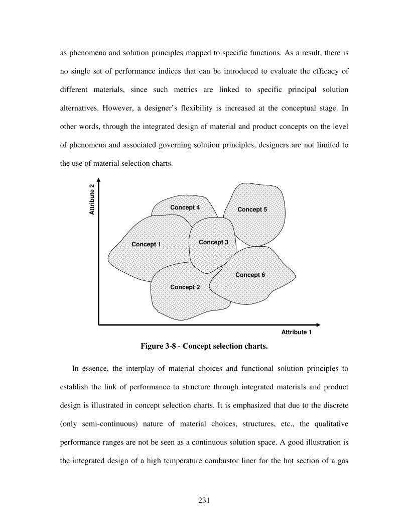
231
as phenomena and solution principles mapped to specific functions. As a result, there is
no single set of performance indices that can be introduced to evaluate the efficacy of
different materials, since such metrics are linked to specific principal solution
alternatives. However, a designer’s flexibility is increased at the conceptual stage. In
other words, through the integrated design of material and product concepts on the level
of phenomena and associated governing solution principles, designers are not limited to
the use of material selection charts.
Att
rib
ute
2
Attribute 1
Concept 2
Concept 5
Concept 1 Concept 3
Concept 6
Concept 4
Figure 3-8 - Concept selection charts.
In essence, the interplay of material choices and functional solution principles to
establish the link of performance to structure through integrated materials and product
design is illustrated in concept selection charts. It is emphasized that due to the discrete
(only semi-continuous) nature of material choices, structures, etc., the qualitative
performance ranges are not be seen as a continuous solution space. A good illustration is
the integrated design of a high temperature combustor liner for the hot section of a gas
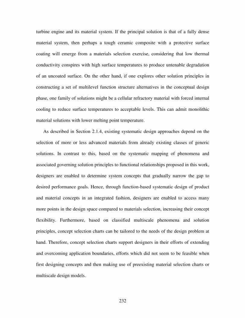
232
turbine engine and its material system. If the principal solution is that of a fully dense
material system, then perhaps a tough ceramic composite with a protective surface
coating will emerge from a materials selection exercise, considering that low thermal
conductivity conspires with high surface temperatures to produce untenable degradation
of an uncoated surface. On the other hand, if one explores other solution principles in
constructing a set of multilevel function structure alternatives in the conceptual design
phase, one family of solutions might be a cellular refractory material with forced internal
cooling to reduce surface temperatures to acceptable levels. This can admit monolithic
material solutions with lower melting point temperature.
As described in Section 2.1.4, existing systematic design approaches depend on the
selection of more or less advanced materials from already existing classes of generic
solutions. In contrast to this, based on the systematic mapping of phenomena and
associated governing solution principles to functional relationships proposed in this work,
designers are enabled to determine system concepts that gradually narrow the gap to
desired performance goals. Hence, through function-based systematic design of product
and material concepts in an integrated fashion, designers are enabled to access many
more points in the design space compared to materials selection, increasing their concept
flexibility. Furthermore, based on classified multiscale phenomena and solution
principles, concept selection charts can be tailored to the needs of the design problem at
hand. Therefore, concept selection charts support designers in their efforts of extending
and overcoming application boundaries, efforts which did not seem to be feasible when
first designing concepts and then making use of preexisting material selection charts or
multiscale design models.
233
Nevertheless, as described in Section 3.2.4, selection is an integral part of almost
every step in design and many researchers have devoted their work to selection. Hence,
the focus in this work is not on selection of design alternatives, but on generating system
concepts. However, it is emphasized that selection is an integral part of design, especially
in the early stages. From the various engineering selection approaches that have been
proposed, the selection Decision Support Problem (sDSP), reviewed in Section 2.1.2, is
used in this work. Concept evaluation and selection are focused on concept performance,
and associated concept functionality and realizability indicators, while considering
uncertainty in preference and attribute ratings, based on selection Decision Support
Problem (sDSP) implemented in the software DSIDES. Uncertainty in preference and
attribute ratings is accounted for through exact interval arithmetic.
However, the inherent lack of concrete information at the conceptual and early
embodiment stages of design is acknowledged. Hence, not one, but multiple most
promising concepts are further explored through template-based instantiations of
compromise Decision Support Problems (cDSPs) [433], reviewed in Section 2.1.2, before
selection is narrowed down to a single concept. For example, partially instantiated
template-based cDSP formulations (where only the constraints, variables, parameters,
goals, response and analysis entities are instantiated) are used to explore response
surfaces throughout the feasible design space as well as identify extreme values and main
effects. Fully instantiated utility-based cDSP formulations (where driver and objective
entities are instantiated additionally) are then used for multi-objective solution finding to
select a most promising principal solution from the set of feasible concepts identified
earlier.
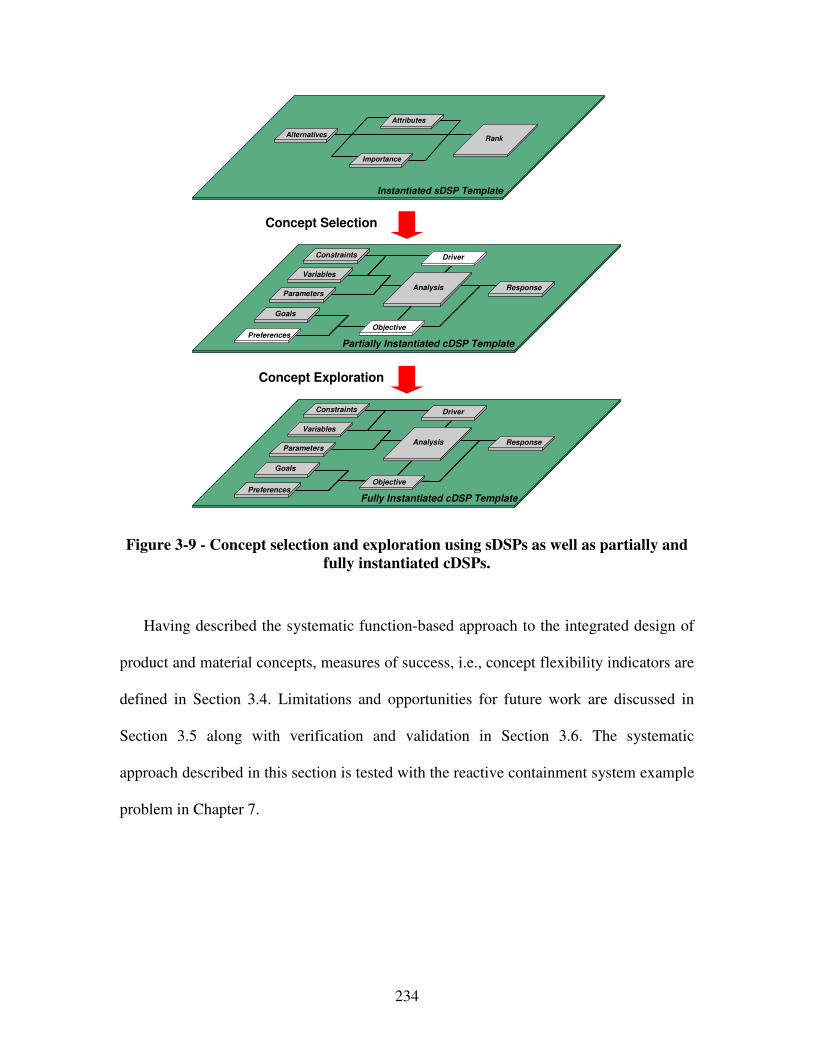
234
Concept Selection
Concept Exploration
AlternativesRank
Instantiated sDSP Template
Importance
Attributes
Goals
Preferences
Variables
Parameters
Constraints
Response
Objective
Analysis
Driver
Fully Instantiated cDSP Template
Goals
Preferences
Variables
Parameters
Constraints
Response
Objective
Analysis
Driver
Partially Instantiated cDSP Template
Figure 3-9 - Concept selection and exploration using sDSPs as well as partially and
fully instantiated cDSPs.
Having described the systematic function-based approach to the integrated design of
product and material concepts, measures of success, i.e., concept flexibility indicators are
defined in Section 3.4. Limitations and opportunities for future work are discussed in
Section 3.5 along with verification and validation in Section 3.6. The systematic
approach described in this section is tested with the reactive containment system example
problem in Chapter 7.
235
3.4 Concept Flexibility Indicators
In order to evaluate whether a designer’s concept flexibility, i.e., ability to explore
and expand a design space, is increased through applying the function-based systematic
approach to the integrated design of product and material concepts developed in this
work, indicators of concept performance ranges, concept functionality, concept
realizability, ease of concept generation, concept variety, concept quantity and concept
novelty have to be determined. These concept flexibility indicators have been derived
from the work of Shah and Vargas-Hernandez [586], who define four metrics to evaluate
different aspects of ideation effectiveness, namely novelty, variety, quality, and quantity,
and define specific procedures for evaluating each. Based on their work, the concept
flexibility indicators used in this work are defined as follows:
• Concept quantity: A measure of the number of ideas generated. This measure is
rooted in the assumption that the generating more ideas increases the chance of
better ideas. As noted by Benami and Jin [55], if many ideas are created during
conceptual design, there can be plenty of options to choose from, and
consequently it is more likely that a good design can be attained.
• Ease of concept generation: A measure of how easy to use the method for
concept generation is. This includes how useful the method is to manage
complexity and uncertainty as well as to facilitate access to domain-expertise.
• Concept variety: A measure of how well the designer is able to explore the
solution space. In this context, generation of a large number of ideas separated by
large distances in the design space translates to high concept variety and thus
concept flexibility. Also, being able to access a more points in the design space
236
and corresponding performance ranges correlates with increased concept
flexibility. It has been shown that being able to reach more points in the design
space through increased concept flexibility correlates strongly to higher quality
design [174].
• Concept novelty: A measure of how unusual or unexpected an idea is compared
to other ideas in the solution set. Novel designs are considered as expanding the
design space since they occupy points not initially perceived as within the design
space. Expanding the design space hence offers the opportunity to find better
designs that are highly non-intuitive or so far not known to exist. However,
concept novelty also refers to the ability of managing and assessing novelty of
concepts.
• Concept functionality and realizability: Measure of functionality and feasibility
of a specific concept to meet performance requirements. Acknowledging the
inherent lack of concrete information during the conceptual and early embodiment
stages of design, rigorous cost analysis is not considered in this work. Here, focus
is on functionality and realizability indicators.

237
3.5 Discussion, Limitations, and Opportunities for Future Work – Function-Based Systematic Approach to the Integrated Design of Product and Material Concepts
The fundamental assumptions underlying the systematic function-based approach
presented in this chapter are:
• accurate and sufficient information has been utilized to clarify the task,
• the system under consideration can be divided into a finite number of
subproblems represented as functions,
• a subproblem can be considered separately and its relations with other
subproblems temporarily suspended,
• subproblems and their solutions can be presented in a morphological matrix,
• appropriate solution-principles have been identified and the associated technology
exists to satisfy functional relationships,
• a global solution to the design problem can be found as a combination of solutions
to the individual subproblems, and
• a global solution is selected in an unbiased way.
The systematic function-based approach is linked to representing systems, i.e., the
coupled product and material system, in terms of the functions to be fulfilled, thereby
representing an abstract solution to the given design problem. In this work functions are
represented based on solution-neutral natural language by combining the nouns energy,
material and signal with a respective verb while taking into account in- and output flows.
However, for material scientists in certain areas, such as the area of “self-healing”
materials, functional representations might have a different meaning. Also, functional
representations are often criticized for being subjective. But, subjective is different than
238
arbitrary. Due to the expressiveness of natural language, a wider range of functions can
be represented which is crucial to accommodate the use of functional representations in
the materials domain. Also, several formal function taxonomies exist and a common
vocabulary that is well-suited for function-based design on the materials level has been
proposed in work. While applying the proposed approach, this common vocabulary and
developed function repositories are to be extended in future work.
The focus in function-based systematic design has so far been on the fields of
mechanical, precision, control, software and process engineering – specifically, on the
design of various types of connections, guides and bearings, power generation and
transmission, kinematics and mechanisms, gearboxes, safety technology, ergonomics, as
well as production processes. Extending the use of functional representations to the
materials domain leveraging structure-property relations on multiple scales thus bridges
the gap between the product domain and the materials domain to the benefit of both
domains. Making use of existing design-catalogs for the product and materials domain as
proposed in Chapter 4 will thus facilitate access to classified and reusable expertise in
both domains. Using functional representations as the common interface will thus lead to
increased integration of both domains, as well as increased transparency, modularity, and
reconfigurability of design processes resulting in increased concurrency of design
activities. Using solution-neutral functional formulations the designer is thus encouraged
to think more deeply about the fundamental phenomena and solution principles.
By focusing on phenomena and associated solution principles to embody functional
representations in the function-based systematic approach proposed in this Chapter, the
method becomes applicable in both domains equally well. As described above,
239
phenomena are physical effects that can be described in terms of mathematical equations
– the universal language in science and engineering. Also, solution principles associated
with certain phenomena are further embodying phenomena. Hence, they may range from
various configurations of “active” surfaces in for example gearboxes, to various
realization processes in product manufacturing, or even various materials structure-
property relations, such as atomic configurations resulting in different macroscopic
effects. But, operating at the level of functionality, fundamental phenomena, and
associated solution principles requires more “active engagement” of designers as
compared to material selection of having determined the system concept. Also, a certain
level of understanding fundamentals in materials science is required. However, by
operating at the level of functionality, fundamental phenomena and associated solution
principles, a particular material system is only illustrative of the possibilities, not their
determinant.
The problem-directed systematic approach to conceptual materials design presented
in this work is based on systematic variation of functional relationships, phenomena and
associated solution principles. Hence, it leads to comprehensive design space expansion
and exploration. However, if non-feasible phenomena or solution principles are not
eliminated early enough, this comprehensive design space expansion and exploration
may result in “concept explosion”. Hence, systematic variation is to be exercised with
care in order to explore a variety of concepts. But, it may potentially result in the
generation of novel concepts, either by identifying new phenomena or solution principles
to pursue or by combining known phenomena and solution principles to something new.
However, it is a powerful attention-directing tool to guide the ability of designers through
240
a broad solution space, ensuring that nothing essential has been overlooked or ignored,
and fostering inventiveness in multiple disciplines. Also, when using a systematic
approach, a designer does not rely on coming up with a good idea at the right moment in
time and may always trace back and reevaluate completed steps to further increase
concept flexibility and thereby satisfy dynamic demands.
Evidence from practice shows that more innovative solutions frequently emerge from
function-based systematic approaches and the logic underpinning these solutions is more
clearly understood [470]. However, even if an intuitively generated solution is selected in
the end, the result of applying the function-based systematic approach to the integrated
design of product and material concepts as described above is i) a more thorough search
through, ii) an informed decision making, as well as iii) an expansion of the design space
and hence increase in concept flexibility, which is crucial when facing dynamic demands
in a global marketplace.
In this work, concept quantity, ease of concept generation, concept variety and
novelty as well as concept functionality and realizability are used as concept flexibility
indicators to drive systematic concept selection considering multiple criteria. These
indicator are not sufficient for all aspects of importance when evaluating concepts with
respect to a product’s life-cycle – starting from the product’s proposal and performance
requirements, spanning it’s design, realization, use, and evolution, recycling or proposal.
But, these indicators are appropriate to evaluate the information available at these early
stages of design. If for example a product’s embodiment design is not known, cost
estimations are less a matter of rigorous analysis and hence of little use. However,
241
indicators and metrics to evaluate concepts and their level of satisfaction with respect to
performance requirements should be focus in future work.
Also, integrating function-based systematic design with set-based concept modeling
tools acknowledging the inherent lack of detailed information in the early phases of
design is crucial. For example, due to the ill-structured nature of conceptual design,
objectives and constraints are not clearly understood in the early stages of design. Also,
conceptual design involves different abstract levels of thinking including mere function
structures or rough sketches. Hence, capturing concepts at different abstract levels is
required during modeling. Furthermore, if available, simulation models are evolving and
far from being complete. Hence, formal and informal decision-making must be
accommodated in solution finding and selection methods.
In future work, selection methods should also be advanced to better address
multiscale or hierarchical problems in the context of integrated product and materials
design or in the context of designing complex engineered systems in general. To support
a human decision maker in processing both quantitative and qualitative information on
multiple levels and scales, template-based systematic selection methods for a distributed,
team-based environment should be developed. Due to the inherent lack of knowledge in
the conceptual and early embodiment stages of design, these methods must both capture
“objective” quantitative information and “subjective” experience-based knowledge of
the human decision-maker in a group setting.
Also, in order to better evaluate generated concepts, concept representations tools
should be extended. So far, focus has been on intuitive geometry modeling tools for
conceptual design, such as sketching systems [375, 519, 763], vague discrete modeling
242
[273], rough sketches, flow diagrams, text notes, or rapid prototypes and digital clay
among others. Integration of such intuitive geometry modeling tools with function-based
systematic design and retrieving or classifying concepts in different representations is an
area of further research. Also, tools are required to facilitate collaborative decision
making in distributed design environments. This includes distributed functional and
geometric modeling systems. Also required are methods for negotiation during
conceptual design. However, integration of human interactivity must be ensured to
facilitate many creative activities during conceptual design. The computer is meant to
support human decision making, not vice versa.
3.6 On Verification and Validation – Theoretical Structural Validation
In this chapter, theoretical structural validation as one aspect of the validation square
is addressed. An overview of the validation performed in this dissertation is presented in
Section 1.3. Specific details related to validating the function-based systematic approach
presented in this Chapter are illustrated in Figure 3-10.
Theoretical structural validation refers to accepting the validity of individual
constructs used in the systematic approach and accepting the internal consistency of the
way the constructs are put together. Theoretical structural validation is carried out in this
chapter using a systematic procedure consisting of i) identifying the method’s scope of
application, ii) reviewing the relevant literature and identifying the strengths and
243
limitations of the constructs in the literature, and iii) identifying the gaps in existing
literature, and iv) determining which constructs are leveraged in the systematic approach
while exploring the advantages, disadvantages, and accepted domain of application. The
internal consistency of the individual constructs is checked by a critical review of the
literature.
Concerning the general methods of functional analysis, abstraction, synthesis, and
systematic variation, it has been argued why these general methods are appropriate for
concept generation for the integrated design of product and material concepts and
materials design in particular. Based on the existing literature, it is shown that these
general methods have been previously used and validated in the context of other
systematic design methods in various domains successfully. However, these general
methods have not been used in a function-based systematic method on the materials level
and for integrated design of product and material concepts as proposed in this work.
From the critical review of the literature, it is identified that focus of any function-
based systematic method has so far been on mechanical, precision, control, software, and
process engineering domain-specific applications, such as connections, guides and
bearing, power generation and transmission, kinematics, gearboxes, safety technology,
ergonomics as well as production processes. Existing function-based systematic design
approaches depend on the selection of more or less advanced materials from already
existing classes of generic solutions. Furthermore, in general engineering practice, the
focus is more on product-oriented approaches, that are prone to solution fixation and
intuition when generating concepts. Hence, the focus in this work is on systematic
problem-oriented conceptual design, based on a functional decomposition and

244
representation of the design-problem in solution-neutral natural language taking into
account in- and output flows. Operating at the level of phenomena and associated
solution principles on various system levels as well as the multiscale materials level,
conceptual design efforts in the product and materials domain are thus integrated and
conceptual materials design is rendered more systematic and domain-independent,
thereby increasing a designer’s concept flexibility compared to the baseline designer.
Due to the logical procedure of literature review, gap analysis, as well as
development and evaluation of a new function-based systematic approach for conceptual
materials design, the theoretical structural validity of the individual constructs is
accepted. Accepting internal consistency of the way constructs are put together is
investigated in Chapter 6.
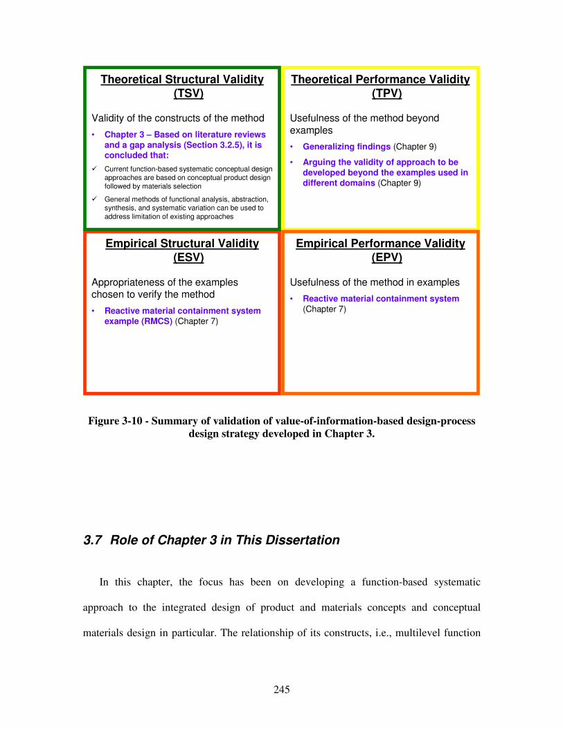
245
Empirical Structural Validity (ESV)
Appropriateness of the exampleschosen to verify the method
• Reactive material containment system example (RMCS) (Chapter 7)
Theoretical Performance Validity (TPV)
Usefulness of the method beyond
examples
• Generalizing findings (Chapter 9)
• Arguing the validity of approach to be developed beyond the examples used in different domains (Chapter 9)
Theoretical Structural Validity (TSV)
Validity of the constructs of the method
• Chapter 3 – Based on literature reviews and a gap analysis (Section 3.2.5), it is concluded that:
� Current function-based systematic conceptual design
approaches are based on conceptual product design
followed by materials selection
� General methods of functional analysis, abstraction,
synthesis, and systematic variation can be used to
address limitation of existing approaches
Empirical Performance Validity (EPV)
Usefulness of the method in examples
• Reactive material containment system (Chapter 7)
Figure 3-10 - Summary of validation of value-of-information-based design-process
design strategy developed in Chapter 3.
3.7 Role of Chapter 3 in This Dissertation
In this chapter, the focus has been on developing a function-based systematic
approach to the integrated design of product and materials concepts and conceptual
materials design in particular. The relationship of its constructs, i.e., multilevel function
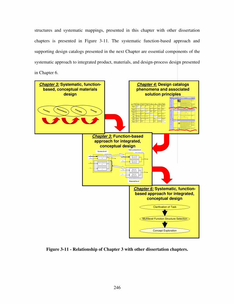
246
structures and systematic mappings, presented in this chapter with other dissertation
chapters is presented in Figure 3-11. The systematic function-based approach and
supporting design catalogs presented in the next Chapter are essential components of the
systematic approach to integrated product, materials, and design-process design presented
in Chapter 6.
Chapter 6: Systematic, function-based approach for integrated,
conceptual design
Multilevel Function Structure Selection
Clarification of Task
Concept Exploration
Chapter 4: Design catalogs phenomena and associated
solution principles
Chapter 3: Function-based approach for integrated,
conceptual design
Pheno-menon
Scale Properties Applications
"Monolithic" materials
- Metals Compared to all other classes of material, metals ar e stiff, strong and tough, but
they are heavy. They have relatively high melting points. Only one metal - gold - is
chemically s table as a metal. Metals are ductile, allowing them to be shaped by
roll ing, forging, drawingn and extrusion. They are easy to machine with precision,
and they can be joined in many di fferent ways . Iron and nickel are trans itional
metals involving both metall ic and covalent bonds, and tend to be less ductile than
other metals. However, metals conduc t elec tricity well , reflec t light and are completely opaque. Primary pr oduction of metals is energy intensive. Many
require at least twice as much energy per unit weight than commodity polymers.
But, metals can general ly be recycled and the energy required to do so is much
less than that requried for primary production. Some are tox ic, others ar e so inert
that they can be implanted in the human body.
- A luminum-, copper- ,
magnesium-, nickel-, steel-,
titanium-, z inc -al loys
- Car bon-, stainles-, …
steels
- Amor phous metals, …
Ela
stic
/in
ela
sti
c d
efo
rma
tio
n (
ten
sio
n,
co
mpre
ssio
n, b
en
din
g,
sh
ea
r, t
ors
ion
, bu
cklin
g, fr
actu
re,
cu
ttin
g, in
vers
ion
, e
xtr
usio
n,
Characteristics
Solution Principle
- Polymers
From a macroscale, monoli thic materials are r efer red to as matter, i .e., the substance of which physical objects ar e composed.
Polymers feature an immense range of form, color, surface finish, translucency,
transparency, toughness and flexibil ity. Ease of molding allows shapes that in
other materials could only be bui lt up by expensive assembly methods. Their
excellent workabi lity al lows the molding of complex forms , allowing cheap manufacture of integrated components that previously were made by assembling
many par ts. Many polymers are cheap both to buy and shape. Most res ist water,
acids and alkalis wel l, though organic solvents attack some. A ll are light and many
are flexible. Their properties change rapidly with temperature. Even at room
temperature many cr eep and when cooled they may become brittle. Polymers
generally are sens itive to UV radiation and to strongly oxidizing env ironments.
- Thermosplastic polymers :
ABS, Cellulose, Ionomers ,
Nylon/PA, PC, PEEK, PE,
PMMA, POM, PP, PS, PTFE, tpPVC, tpPU,
PET/PETE/PBT
- Thermosetting polymers:
Epoxy, Phenolic , Polyester,
tsPU, tsPVC
- E las tomers: Acrylic
machining.
Honeycomb-core
sandwiches
- In-plane honeycombs Cor e cel l axes of in-plane honeycomb cores are oriented paral lel to the face-sheets. They provide potentials for decreased conductivity and fluid flow within
cells. Relative densities range from 0.001 to 0.3. Their densification s train can be
approx imated as:
Their relative s ti ffness can be approximated as:
Their relative s tr ength can be approximated as:
- P rismatic- , square-, chiracal- , etc . core in-plane
honeycombs
- Out-of- plane honeycombs Cor e cel l axes of out-of-plane honeycomb cores ar e oriented perpendicular to face-sheets. They provide potentials for decr eased conductivity. Relative dens ities
range from 0.001 to 0.3. Their densification strain can be approximated as:
Their relative s ti ffness can be approximated as:
Their relative s tr ength can be approximated as:
- Hexagonal- , sqaure-, etc. cor e put-of-plane
honeycombs
Fiber-composites
- Continuous fiber
composites
Continuous fiber composites are composites with highes t stiffness and s trength.
They ar e made of continuous fibers usually embedded in a thermosetting r esin.
The fibers carry the mechanical loads while the matrix mater ial transmits loads to
the fibers and provides ductili ty and toughness as well as protecting the fibers from damage caused by handling or the environment. It is the matrix mater ial that
l imits the service temperature and processing conditions. On mesoscales, the
proper ties can be strongly influenced by the choice of fiber and matrix and the
way in which these are combined: fiber -res in ratio, fiber length, fiber orientation,
laminate thickness and the presence of fiber/resin coupling agents to improve
bonding. The strength of a composite is inc reased by raising the fiber-resin ratio,
and orienting the fibers parallel to the laoding direction. Increased laminate
thickness leads to reduced composite s trength and modulus as there is an
incr eased l ikelihood of entrapped voids. Environmental conditions affect the
performance of composites: fatigue loading, moisture and heat al l
reduce allowable strength. Polyesters are the most most widely used matrices as they offer reasonable properties at relatively low cost. The superior properties of
epoxies and the termperature per formance of polyimides can justify their use in
certain appl ications, but they are expensive.
- Glass fiber s [high strength
at low cost], polymer fibers
(or ganic (e.g., Kevlar) or
anorganic (e.g., Nylon, Polyester)) [reasonable
properties at relatively low
cos t], carbon fibers [very high
strength, stiffness and low
density]
- S trands, fi laments, fibers,
yarns (twis ted strands),
rov ings (bundled strands)
- Nonwoven mattings ,
weaves, braids , knits, other
- Discontinuous fiber
composites
Polymers reinforced with chopped polymer, wood, glass or carbon fibers are
referr ed to as discontinuous fiber composites. The longer the fiber, the more
efficient is the reinfor cement at carrying the applied loads , but shorter fibers are
eas ier to process and hence cheaper. Hence, fiber length and mater ial are the governing design variables. However, fibr ous core composites feature shape
flexibil ity and relatively high bending stiffness at low dens ity.
- Glass fiber s, polymer fibers
(or ganic (e.g., Kevlar) or
anorganic (e.g., Nylon,
Polyester)), carbon fibers
Me
so
scale
Ela
sti
c/i
ne
las
tic
de
form
ati
on
(te
ns
ion
, c
om
pre
ss
ion
, b
en
din
g,
sh
ea
r, t
ors
ion
, b
uc
kli
ng
, fr
actu
re,
cu
ttin
g,
inve
rsio
n,
ex
tru
sio
n,
dra
win
g,
flo
w)
Honeycomb-core sandwiches take their name from their visual resemblance to a bee's honeycomb. With control lable core dimensions
and topologies on mesoscales, they freature relatively high s ti ffness and yield strength at low density. Large compressive strains are
achievable at nominally cons tant stress ( before the material compacts), yielding a potentially high energy absorption capacity. Honeycomb-core sandwiches have acceptable str uctur al performance at relatively low costs with useful combinations of thermophysical and
mechanical properties. Usual ly, they provide benefits with respect to multiple use.
The combination of polymers or other matrix materials with fibers has given a range of light materials with sti ffness and s tr ength
compar able to that of metals. Commonly, resin materials ar e epoxies , polyesters and vinyls. Fibers are much stronger and stiffer than
their equivalent in bulk form because the drawing process by they are made orients the polymer chains along the fiber axis or reduces the density of defects.
−≈
s
D ρ
ρε 4.11
31 rel
sE
Eρ≈
rel
ys
yρ
σ
σ5.0≈
rel
sE
Eρ1≈
rel
ys
yρ
σ
σ1≈
−≈
s
Dρ
ρε 4.11
Output
Input
Mechanical
Energy
(In)elastic de-
formationInertia
…
Electrostric-tion
…
Magnetostric-tion
…
Impact…
Friction…
Pressure change
…
Dislocation hardening
…
Electrostatic
Energy
Electric field
…
Interference
…
Hall-effect
…
Electrostric-tion
…
Photostric-tion
…
Electrical resistance
…
Galvanic element
…
Magnetostatic
Energy
Magnetic field
…
Oscillating circuit
…
Ferromag-netism
…
Magneto-striction
…
Farraday-effect
…
Eddy current
…
Sound
Energy
Pressure wave
…
Electrostric-tion
…
Magnetostric-tion
…
Reflection
…
Noise dam-ping
…
Elasticity
…
Light
Energy
Electromag-netic radiation
…
Photostric-tion
…
Absorption
…
Refraction
…
Thermolumi-nescence
…
Photoeffect
…
Thermal
Energy
Thermal expansion
…
Thermoelectricity
…
Curie-Weiss law
…
Pyro-electricity
…
Convection
…
Phase trans-formation
…
Molecular
Energy
Exothermic reaction
…
Molecular dipoloe
…
Fluores-cence
…
CombustionConductivity
…
Adhesion
…
Light
Energy
Thermal
Energy
Molecular
Energy
Mechanical
Energy
Electrostatic
Energy
Magnetostatic
Energy
Sound
Energy
Chapter 3: Systematic, function-based, conceptual materials
design
Advanced mult ifunctional material
Ex,in
Mx,in
Ex,in
System boundary
System function x Exyz,out
System function z
System function y
Ey,in
Sz,in
Mx,in Sub-system function xx
Ex,out
Sub-system function xy
Sz,in
Ey,in Material function yx
Eyz,out
Material function zx
Sub-system boundary System level
Sub-system level
Material level
Concept
Principle
Phenomenon
Function
Figure 3-11 - Relationship of Chapter 3 with other dissertation chapters.
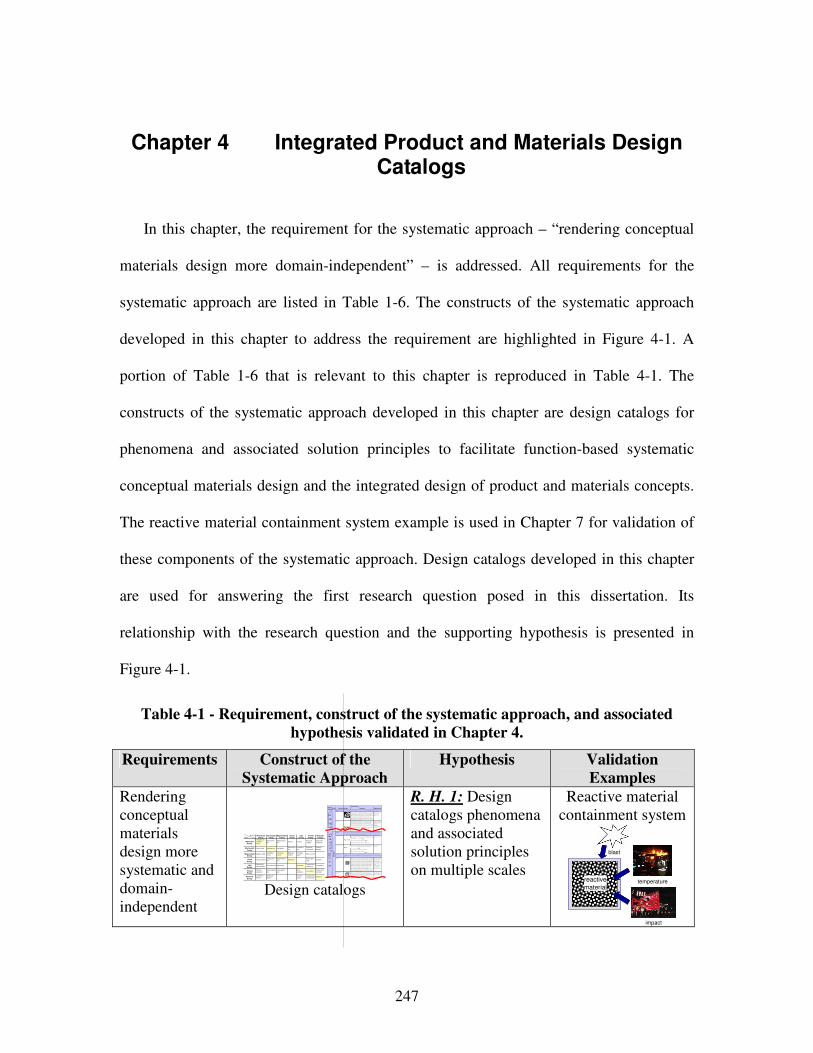
247
Chapter 4 Integrated Product and Materials Design Catalogs
In this chapter, the requirement for the systematic approach – “rendering conceptual
materials design more domain-independent” – is addressed. All requirements for the
systematic approach are listed in Table 1-6. The constructs of the systematic approach
developed in this chapter to address the requirement are highlighted in Figure 4-1. A
portion of Table 1-6 that is relevant to this chapter is reproduced in Table 4-1. The
constructs of the systematic approach developed in this chapter are design catalogs for
phenomena and associated solution principles to facilitate function-based systematic
conceptual materials design and the integrated design of product and materials concepts.
The reactive material containment system example is used in Chapter 7 for validation of
these components of the systematic approach. Design catalogs developed in this chapter
are used for answering the first research question posed in this dissertation. Its
relationship with the research question and the supporting hypothesis is presented in
Figure 4-1.
Table 4-1 - Requirement, construct of the systematic approach, and associated
hypothesis validated in Chapter 4.
Requirements Construct of the
Systematic Approach
Hypothesis Validation
Examples
Rendering conceptual materials design more systematic and domain-independent
Pheno-
menonScale Properties Applications
"Mon olit hic" m ater ials
- M etals Co mpare d to all othe r classes of m aterial, m etals ar e stiff, stro ng and t ough, bu t
they are heavy. Th ey have relat ively high melting po in ts. Only one m etal - gold - is
chemically stable as a metal. M etals are d uctile, allow in g them to be sha ped by
rolling, for ging, dr awing n and e xt rusion. T hey are easy to ma chine w ith precision,
and the y ca n be joined in many diffe rent w ays. Ir on and n icke l are tr ansitional
metals involving bo th meta llic and covalent bon ds, and te nd to be less ductile than other metals. H ow ever, metals cond uct electricity w ell, reflect light and ar e
completely opa que. P rimar y produ ctio n of m etals is energ y int ensive. Many
requir e at least tw ice as m uch ene rgy per unit w eight than commo dity polymers.
But, metals can g enera lly be recycled and the ener gy requ ir ed to d o so is much
le ss than tha t requ ried for primar y produ ction. S ome ar e toxic, othe rs are so inert
that the y ca n be implan ted in the human body.
- A luminum- , coppe r-,
magne siu m-, nickel- , steel-,
titanium- , zin c-alloys
- C arb on-, sta in les- , …
steels
- A morp hous me tals, …
Ela
stic
/in
ela
sti
c d
efo
rm
ati
on
(te
nsio
n, co
mp
ressio
n, b
en
din
g,
sh
ear, to
rsio
n, b
ucklin
g, fr
actu
re,
cutt
ing,
inversio
n, e
xtr
usio
n,
Characteristics
Solution Principle
- P olymer s
Fr om a m acroscale, m onolithic ma terials are refer red to as matte r, i.e., th e substance of w hich physical objects a re com posed.
Polymer s featur e an im mense r ange o f form , color, sur face finish, translucency,
transpa rency, toug hness and flexibility. E ase of molding allow s shap es that in
other mater ia ls co uld only be built up by expensive asse mbly metho ds. The ir
excellent w orkab ility allow s the m olding of com plex for ms, allow ing cheap
manufa cture o f integra ted comp onents th at pre viou sly w er e made by assembling
many par ts. Many p olym ers ar e cheap both to b uy and shap e. Most r esist w ater,
acids and alkalis w ell, thoug h orga nic solvents attack so me. A ll are light a nd man y
are flexible. Their p roper ties change rapidly w ith temp eratur e. E ven at r oom
temper ature many cre ep and whe n cooled th ey may becom e brittle. Polymer s gener ally ar e sensitive to U V radiat io n and to strongly oxidizing en vir onmen ts.
- T hermo splastic polymers:
AB S, Cellulose, Ionome rs,
Nylon/ PA , PC , P EE K , PE ,
PMM A, P OM, P P , PS , P TFE ,
tpPV C , tpP U ,
PE T/P ET E/ PB T
- T hermo setting polyme rs:
Epo xy, P hen olic, P olyester ,
tsPU , tsP VC - E lastomer s: Acr ylic
machining.
H one ycom b-c ore
san dwich es
- In -plane h oneycombs Co re cell axes of in -plane h oneycomb cores ar e orien ted par alle l t o the fa ce-
sheets. T hey provide potentials fo r decr eased cond uctivity a nd fluid flow w ithin
cells. Relat ive densities ran ge fro m 0.001 to 0.3. Their d ensification stra in can be
appro xim ated as:
Their relative stiffne ss ca n be ap proximat ed as:
Their relative stre ngth can be appr oximated as:
- P rismatic-, square -,
chiracal-, etc. core in -plane
honeycom bs
- Ou t-of- plane hon eyco mbs Co re cell axes of out-of -plane h oneycomb cores ar e orient ed per pendicular to
face-she ets. Th ey provide po tentials for decrea se d conductivity. R elative den sit ie s
range from 0.001 to 0.3. T heir den sif ica tio n strain can be app roximate d as:
Their relative stiffne ss ca n be ap proximat ed as:
Their relative stre ngth can be appr oximated as:
- H exago nal-, sqau re-, e tc.
core pu t-of- plane
honeycom bs
Fib er- com pos ites
- C ont in uous fiber
comp osit es
Co ntinuous fibe r comp osit es are co mposites w ith highe st stiffness an d streng th.
They ar e mad e of continu ous fiber s usually embed ded in a th ermo setting re sin.
The f ib ers carr y the me chanical loads w hile the matrix m aterial tr ansmits loads to
the fiber s and pr ovides ductility and to ughness as well as p rotecting the fiber s
from damag e caused b y h andling or the enviro nment. It is the m atrix mat erial that
lim it s the service te mper ature a nd pro cessing conditions. On mesoscales, the prope rties can be strongly influen ced by the ch oice of fiber and m atrix and the
wa y in w hich t hese are combined : fiber- resin ra tio, fiber len gth, fiber orient ation,
la minate th ickn ess and the presen ce of fiber /resin cou plin g agents to impro ve
bonding. The str ength o f a comp osite is increased by raising the fiber- resin ra tio ,
and or ie nting the f ib ers par allel to the lao ding direction . Increa sed laminate
thickness leads to reduced composite strength and m odulus as the re is an
in creased likelihoo d of entr apped voids. En vir onmen tal conditions af fect the
perfor mance of comp osites: fatigue lo ading, m oist ure an d heat a ll reduce allo wab le strengt h. Po lyeste rs are the mo st most w idely used m atrices as
they offer reaso nable pr operties a t relatively low cost. T he super io r pro perties o f
epoxies and the ter mper ature p erfor mance o f polyimides can ju stif y t heir use in
certain ap plica tions, but th ey are e xp ensive.
- Glass fiber s [high str ength
at low cost], polyme r fiber s
(org anic (e.g. , Kevlar ) or
anorg anic (e.g. , Nylon,
Polyester )) [r easona ble
prope rties at r elatively low cost], carb on fiber s [very high
strengt h, stiffness an d low
density]
- S trand s, fila ments, f ib ers,
ya rns (t wisted strands) ,
rovings ( bundled str ands)
- N onw oven m attings,
we aves, bra id s, knits, other
- D iscontinuo us fiber
comp osit es
Polymer s reinfo rced w ith chop ped polyme r, w ood, g la ss or carb on fiber s are
refer red to as discontinuou s fiber com posites. T he longer the fibe r, the more
efficient is the r einforce ment a t carrying t he applied loa ds, but sho rter fibers ar e easier to process an d hence ch eaper . He nce, fiber length an d mate rial are t he
governing design var ia bles. H ow ever, fibr ous core composites f eature shape
flexibility and relatively high be nding stiffne ss at low density.
- Glass fiber s, polymer fibers
(org anic (e.g. , Kevlar ) or
anorg anic (e.g. , Nylon, Polyester )), ca rbon f ib ers
Mesoscale
Ela
stic
/in
ela
stic
def
orm
atio
n (t
ensi
on
, com
pre
ssio
n, b
en
din
g, s
hear
, tor
sion
, bu
cklin
g, fr
actu
re,
cutt
ing
, in
ver
sion
, ext
rusi
on, d
raw
ing,
flo
w)
H oneycomb -core sa ndw ich es take th eir nam e from their visual r esemblan ce to a be e's honeycomb . W it h contro llab le core dim ensions
and to pologies on m esoscales, th ey freatu re re la tive ly high stiffness and yield st rength at low density. Lar ge com pressive stra in s are
achievable a t nominally consta nt stress ( befor e the m aterial com pacts), yielding a potentially high e nergy ab so rption ca pacity. H oneycomb-
core sa ndw ich es have acce ptable stru ctural pe rform ance at relatively low costs w ith useful com binations of therm ophysical and
mecha nical prope rties. U sually, they pr ovid e benef its with r espect to multiple use.
The combination of polyme rs or o ther m atrix ma terials w ith fibers h as given a r ange o f lig ht mate rials w ith stiffness and strengt h
compa rable to that of m etals. C omm only, resin m aterials ar e epoxies, p olye sters and vin yls. F ibers ar e much stronge r and stif fer tha n
their e quivalent in bu lk f orm b ecause the draw ing pr ocess by they ar e ma de orient s the polyme r chains alon g the fiber axis or r educes th e
density of d efects.
−≈
s
D ρρ
ε 4.11
31 r el
sE
Eρ≈
rel
ys
y ρσ
σ5.0≈
rel
sE
Eρ1≈
rel
ys
y ρσ
σ1≈
−≈
s
D ρρ
ε 4.11
Design catalogs
R. H. 1: Design catalogs phenomena and associated solution principles on multiple scales
Reactive material containment system
temperature
impact
reactive
material
blast
OutputInput
MechanicalEnergy
( In)elastic de-
formation
Inertia
…
Electrostric-
tion
…
Magnetostr ic-
tion
…
Im pact
…
Friction
…
Pressure
change
…
Dislocation
hardening
…
Electrostatic
EnergyElectric fie ld
…
Interference
…
Hall-effect
…
Electrostric-
tion
…
Photostr ic-
tion
…
Electrical
resistance
…
Galvanic
element
…
MagnetostaticEnergy
Magnetic field
…
Oscillating
circuit
…
Ferromag-
netism
…
Magneto-
striction
…
Farraday-
effect
…
Eddy current
…
Sound
EnergyPressure wave
…
Electrostric-
tion
…
Magnetostr ic-
tion
…
Reflection
…
Noise dam-
ping
…
Elasticity
…
LightEnergy
Electromag-
netic radiation
…
Photostric-tion
…
Absorption
…
Refraction
…
Thermolumi-
nescence
…
Photoeffect
…
ThermalEnergy
Thermal
expansion
…
Thermoelectri
city
…
Curie-Weiss
law
…
Pyro-
electricity
…
Convection
…
Phase trans-
form ation
…
Molecular
Energy
Exotherm ic
reaction
…
Molecular
dipoloe
…
Fluores-
cence
…
Combustion
Conductivity
…
Adhesion
…
LightEnergy
ThermalEnergy
MolecularEnergy
MechanicalEnergy
ElectrostaticEnergy
MagnetostaticEnergy
SoundEnergy
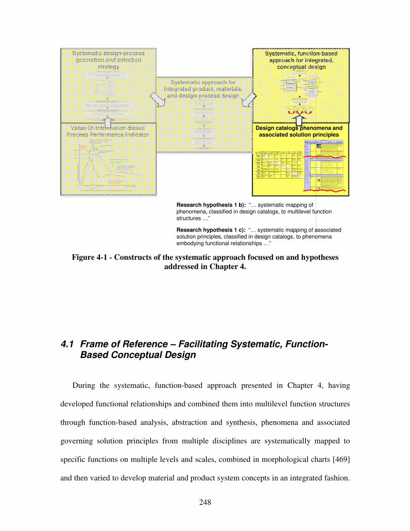
248
Research hypothesis 1 b): “… systematic mapping of phenomena, classified in design catalogs, to multilevel functionstructures …”
Research hypothesis 1 c): “… systematic mapping of associated solution principles, classified in design catalogs, to phenomenaembodying functional relationships …”
Systematic design-process generation and selection
strategy
Value-Of-Information-Based Process Performance Indicator
Systematic approach for integrated product, materials,
and design-process design
Design catalogs phenomena and associated solution principles
Systematic, function-based approach for integrated,
conceptual design
Systematic mapping of classified phenomena and
solution principles from multiple scales and
disciplines to multilevel function structures
Creating multilevel function structures based on
functional analysis, abstraction and synthesis
Ex,in
M x,in
Ex,in
System boundary
System function x Exyz,out
System function z
System function y
Ey,in
Sz,i n
M x,in Sub-system function xx
Ex,out
Sub-system function xy
Sz,in
Ey,in Material function yx
Eyz,out
Material function zx
Sub-system boundarySystem level
Sub-system level
Material level
Clarification of Task
Multilevel Function Structure Selection
Concept Selection
Concept
Principle
Phenomenon
Function
Pheno-menon
Scale Properties Applications
"Monolithic" materials
- Metals Compared to a ll other classes of material , metals are stif f, strong and tough, but
they are heavy. They have rel atively hi gh melti ng points. Only one metal - gold - is
chemically stable as a metal . Metals are d uctile, all owing them to be shaped by
roll ing, forgin g, drawi ngn and extrusion. They are easy to machine with precision, and they can be j oined i n many different ways. Iron an d nickel are transit ional
metals involving both metallic and covalent bonds, and tend to be less d uctile than
other meta ls. However, metals conduct electricity well , ref lect light a nd are
completely opaque. Pri mary producti on of metals is ene rgy i ntensive. Man y
require at least twice as much energy per un it weight than commodity polymers.
But, metals can general ly be recycl ed and the energy required to do so is much l ess than that requried for primary production. Some are toxi c, others are so inert
that they can be i mpl anted in the human body.
- Al uminum-, copper-,
magnesi um-, nickel-, steel -,
ti tanium-, zinc-al loys
- Carbon-, stainles-, … steels
- Amorphous meta ls, …
Ela
sti
c/in
ela
sti
c d
efo
rmat
ion
(te
ns
ion
, c
om
pre
ssi
on
, be
nd
ing
, sh
ear
, to
rsio
n,
bu
ckl
ing
, fr
actu
re, c
utt
ing
, in
ver
sio
n, e
xtr
usi
on
,
Characteristics
Solution Principle
- Pol ymers
From a macroscale, monolith ic materials are referred to as matter, i.e., the substance of which physi cal objects are composed.
Polymers feature an immense range of form, color, surface fini sh, transluce ncy, transparency, toughness a nd f lexibility. Ease of moldi ng all ows sh apes that i n
other mate ri als could only be bui lt up by expensive assembly methods. Their
excellent workabili ty all ows the mol ding of complex forms, al lowing cheap
manufacture of i ntegrated components that previously were made b y assembling
many parts. Many polymers are cheap both to b uy and shape. Most resist water,
acids and alkali s well, though organic so lvents attack some. All are light and ma ny are fl exibl e. Their properties change rapidly with temperature. Even at room
temperature many creep and when cooled the y may become brit tl e. Pol ymers
generall y are sensiti ve to UV radiation and to strongly oxidi zing environments.
- Thermosplastic p olymers: ABS, Cellulose, Ionomers,
Nyl on/PA, PC, PEEK, PE,
PMMA, POM, PP, PS, PTFE,
tpPVC, tpPU,
PET/PETE/PBT
- Thermosett ing pol ymers: Epoxy, Phenolic, Pol yester,
tsPU, tsPVC
- El astomers: Acrylic
machining.
Honeycomb-cor e
sandwiches
- In-plane honeycombs Core cel l axes of in-plane honeycomb cores are oriented paral lel to the face-
sheets. They provide potenti als for decreased conductivity and f luid f low within
cells. Relative densit ies range from 0.001 to 0.3. Their densif icatio n strain can be
approximated as:
Their relat ive st iffness can be approximated as:
Their relat ive stren gth can be ap proximated as:
- Prismati c-, square-,
chiracal-, etc. core in-plane
honeycombs
- Out-o f-plane honeycombs Core cel l axes of out-of-pl ane honeycomb cores are oriented perpendicular to
face-sheets. They provide potentials for decreased conducti vi ty. Relative densities
range from 0.001 to 0.3. Their densif ication strain can be approxi mated as:
Their relat ive st iffness can be approximated as:
Their relat ive stren gth can be ap proximated as:
- Hexagonal-, sqau re-, etc.
core put-of-plane
honeycombs
Fiber-composite s
- Conti nuous fi ber
composites
Continuous f iber composites are composi tes wi th highest st if fness and strength.
They are made of continuous fibers usuall y embedd ed in a thermosetting resin.
The f ibers carry the mechani cal loads whi le the matrix material transmits loads to the f ibers and provides ducti lity an d toughness as well as protecting the fibers
from damage caused by h andling or the environmen t. I t is the matrix material that
l imi ts the service temperature and proce ssing conditio ns. On mesoscales, the
propert ies can be strongly i nfluenced by the choice of f iber and matrix and the
way i n which these are combined: f iber-resin ratio, fi ber length, fi ber orientation,
l aminate thickness and the presence of fiber/resi n coupling agents to improve bondi ng. The strength of a composite is increased by raising the f iber-resin ratio,
and orienting the f ibers parall el to the l aoding di rection. Increased lami nate
thickness leads to reduced composite strength and modulus as there is an
i ncreased likelihood of entrapped voids. Environmental conditi ons affect the
performance of composites: fat igue l oading, moisture and heat all
reduce allowable strength. Polyesters are the most most wi dely used matri ces as they offer reasonable propertie s at relati vely low cost. The superior propert ies of
epoxies and the termperature performance of polyi mide s can justify their use in
certa in appli cations, but they are expensive.
- Glass f ibers [high strength
at low cost], polymer f ibers
(organic (e.g., Kevl ar) or anorganic (e.g., Nylon,
Polyester)) [reasonable
properties at relatively l ow
cost], carbon fibe rs [very high
strength, st if fness and low
density] - Strands, fil aments, fibers,
yarns (twisted strands),
rovi ngs (bundled strands)
- Nonwoven matt ings,
weaves, braids, knits, other
- Disco ntinuous fiber
composites
Polymers rei nforced with chopped polymer, wood, glass o r carb on f ibers are
referre d to as di scontinuous f iber composites. The longer the fi ber, the more
eff ici ent is the reinforcement at carryi ng the appli ed loads, but shorter fi bers are easier to process an d hence cheaper. Hence, f iber length and material are the
governing design variables. However, fibrous core composites fea ture shape
f lexibili ty and relati vely high bendi ng sti ffness at low densi ty.
- Glass f ibers, polymer fibers
(organic (e.g., Kevl ar) or
anorganic (e.g., Nylon, Polyester)), carbon f ibers
Me
so
sca
le
Ela
sti
c/i
ne
lasti
c d
efo
rm
ati
on
(te
ns
ion
, c
om
pre
ssio
n,
ben
din
g, sh
ear,
to
rsio
n,
buc
kli
ng
, fra
ctu
re,
cu
ttin
g,
inve
rsio
n, ex
tru
sio
n, d
raw
ing,
flo
w)
Honeycomb-core sandwiches take thei r name from their visu al resemblance to a bee's honeycomb. W ith controlla ble core di mensions
and topologies on mesoscale s, they freature relatively high stif fness and yield strength at low d ensi ty. Larg e compressive strai ns are
achievable at nominal ly constant stress (before the material compa cts), yieldi ng a potentially hi gh energy absorpti on capacity. Honeycomb-
core sandwiches have acceptabl e structural performance a t rel atively low costs with useful combinations of thermophysical and mechani cal properti es. Usually, they provide benefits with respect to mult iple use.
The combin ation of polymers or other ma trix materi als with f ibers has gi ven a range of light materi als with st iffness and strength
comparable to that of metals. Commonly, resin materi als are e poxi es, pol yesters and vinyls. Fibers are much stronger and stif fer than
thei r equivalent in bulk form because the drawing process by they are made orients the polymer ch ains along the fi ber axis or re duces the
density of defects.
−≈
s
Dρ
ρε 4.11
31rel
sE
Eρ≈
rel
ys
y ρσ
σ5.0≈
rel
sE
Eρ1≈
r el
ys
y ρσ
σ1≈
−≈
s
D ρ
ρε 4.11
OutputInput
MechanicalEnergy
(In)elastic de-formationInertia…
Electrostric-tion…
Magnetostric-tion…
Impact…
Friction…
Pressure change…
Dislocation hardening…
Electrostatic
EnergyElectric field…
Interference…
Hall-effect…
Electrostric-tion…
Photostric-tion…
Electrical resistance…
Galvanic element…
MagnetostaticEnergy
Magnetic field…
Oscillating circuit…
Ferromag-netism…
Magneto-striction…
Farraday-effect…
Eddy current…
SoundEnergy
Pressure wave…
Electrostric-tion…
Magnetostric-tion…
Reflection …
Noise dam-ping…
Elasticity…
Light
Energy
Electromag-netic radiation…
Photostric-tion…
Absorption…
Refraction…
Thermolumi-nescence…
Photoeffect…
ThermalEnergy
Thermal expansion…
Thermoelectricity…
Curie-Weiss law…
Pyro-electricity…
Convection…
Phase trans-formation…
Molecular
Energy
Exothermic reaction…
Molecular dipoloe…
Fluores-cence…
CombustionConductivity…
Adhesion…
Light
Energy
Thermal
Energy
Molecular
Energy
Mechanical
Energy
Electrostatic
Energy
Magnetostatic
Energy
Sound
Energy
Design Variable
Ex
pe
cte
d O
vera
ll P
ayo
ff
Expected payoff usingdesign process alternative 1(global information)
Expected payoff using refined design process alternative 2(global information)
Payoff 2
Decision 1 Decision 2
Payoff 1
Process Performance Indicator 1
Expected payoff using most accurate physical or simulation models(local information)
Process Performance Indicator 2
Decisions based on predicted behavior using design process alternatives 1, 2, 3, etc.
Process Performance Indicator 3
Expected payoff using refined design process alternative 3(global information)
Payoff 3
Decision 3
Template-based decision-centric concept exploration accounting for uncertainty and
complexity of multilevel and multiscale design
Evaluation of design-process alternatives and value of additional multiscale modeling based on
Process Performance Indicator
Multilevel Function Structure Selection
Clarification of Task
Design-Process Design
Embodiment Design
Design-Process Selection
Concept Selection
Creating multilevel function structures based on
functional analysis, abstraction and synthesis
Systematic mapping of classified phenomena and solution principles from multiple scales and
disciplines to multilevel function structures
Systematic generation of multiscale design-process alternatives based on a value-of-
information-based strategy
Evaluation of design-process alternatives and additional modeling potential through a value-of-information-based Process Performance Indicator
Systematic generation of design-process alternatives based on
principles from information economics
Design-Process Evaluation
Design-Process Selection
Concept Exploration and Selection
Template-based decision-centric embodiment design
2) Select and Evaluate Simple Initial
Design Process Alternative.
4) Evaluate most truthful design process alternative available.
Step 7: Select satisficing embodiment
design process alt ernative.
1) Formulate Decision Using
Compromise DSP.
3) Determine Decision Point by Solving cDSP for Maximum Payoff.
High Process Per-
formance Indicator
Low Process Performance
Indicator
5) Evaluate Process Perf ormance Indi cator
Simple Initial Design-Process Alternative .
6) Refine Design-Process and
Repeat Steps 3 Through 5.
…
Figure 4-1 - Constructs of the systematic approach focused on and hypotheses
addressed in Chapter 4.
4.1 Frame of Reference – Facilitating Systematic, Function-Based Conceptual Design
During the systematic, function-based approach presented in Chapter 4, having
developed functional relationships and combined them into multilevel function structures
through function-based analysis, abstraction and synthesis, phenomena and associated
governing solution principles from multiple disciplines are systematically mapped to
specific functions on multiple levels and scales, combined in morphological charts [469]
and then varied to develop material and product system concepts in an integrated fashion.
249
Hence, principal solution alternatives can not only be developed through multilevel
function structure alternatives (as discussed in Chapter 4), but also through embodying a
specific multilevel function structure alternative with different phenomena and associated
solution principles. Therefore, in order to develop wide ranged principal solution
alternatives and increase a designer’s concept flexibility, it is crucial to determine
phenomena and associated solution principles on multiple system levels including the
multiscale materials level.
During conceptual design, designers are currently used to manipulating materials at
the macro-scale only after having determined a system concept. With the new possibility
provided by multiscale design on the materials level, a designer would operate more
efficiently and predictably if they could identify and control directly the root mechanisms
of larger-scale behavior, i.e., property-structure relations, on multiple scales and hence
tailor-make specific material systems to enhance a designer’s concept flexibility. For
example, a strengthening principle associated with (in)elastic deformation on macro- and
mesoscales is limited deformability, on microscales dislocation flow obstructions, on
atomic scales unit cell distortions, etc. Hence, In order to facilitate integrated design of
product and material concepts from a systems perspective at the level of phenomena and
associated solution principles, the development of classification schemes and design
catalogs to support a systems designer in identifying and controlling root mechanisms of
larger-scale behavior on smaller scales directly is the focus in this chapter. Hence, by
focusing on phenomena and associated solution principles but not a specific case or
material artifact, a designer may be able to step out of the technological cycle of
obsolescence and evolution. By operating at the level of phenomena and associated
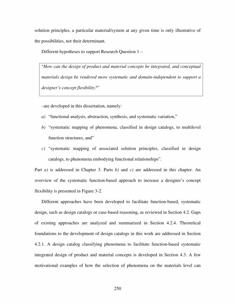
250
solution principles, a particular material/system at any given time is only illustrative of
the possibilities, not their determinant.
Different hypotheses to support Research Question 1 –
“How can the design of product and material concepts be integrated, and conceptual
materials design be rendered more systematic and domain-independent to support a
designer’s concept flexibility?”
–are developed in this dissertation, namely:
a) “functional analysis, abstraction, synthesis, and systematic variation,”
b) “systematic mapping of phenomena, classified in design catalogs, to multilevel
function structures, and”
c) “systematic mapping of associated solution principles, classified in design
catalogs, to phenomena embodying functional relationships”.
Part a) is addressed in Chapter 3. Parts b) and c) are addressed in this chapter. An
overview of the systematic function-based approach to increase a designer’s concept
flexibility is presented in Figure 3-2.
Different approaches have been developed to facilitate function-based, systematic
design, such as design catalogs or case-based reasoning, as reviewed in Section 4.2. Gaps
of existing approaches are analyzed and summarized in Section 4.2.4. Theoretical
foundations to the development of design catalogs in this work are addressed in Section
4.2.1. A design catalog classifying phenomena to facilitate function-based systematic
integrated design of product and material concepts is developed in Section 4.3. A few
motivational examples of how the selection of phenomena on the materials level can
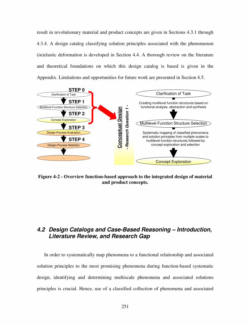
251
result in revolutionary material and product concepts are given in Sections 4.3.1 through
4.3.4. A design catalog classifying solution principles associated with the phenomenon
(in)elastic deformation is developed in Section 4.4. A thorough review on the literature
and theoretical foundations on which this design catalog is based is given in the
Appendix. Limitations and opportunities for future work are presented in Section 4.5.
Multilevel Function Structure Selection
Clarification of Task
Concept Exploration
Co
nc
ep
tual
Desig
n
-R
esea
rch
Qu
es
tio
n 1
-
Creating multilevel function structures based on
functional analysis, abstraction and synthesisMultilevel Function Structure Selection
Clarification of Task
Design-Process Evaluation
…
Design-Process Selection
Concept Exploration
Systematic mapping of classified phenomena and solution principles from multiple scales to
multilevel function structures followed by
concept exploration and selection
STEP 3
STEP 0
STEP 1
STEP 2
STEP 4
Figure 4-2 - Overview function-based approach to the integrated design of material
and product concepts.
4.2 Design Catalogs and Case-Based Reasoning – Introduction, Literature Review, and Research Gap
In order to systematically map phenomena to a functional relationship and associated
solution principles to the most promising phenomena during function-based systematic
design, identifying and determining multiscale phenomena and associated solutions
principles is crucial. Hence, use of a classified collection of phenomena and associated
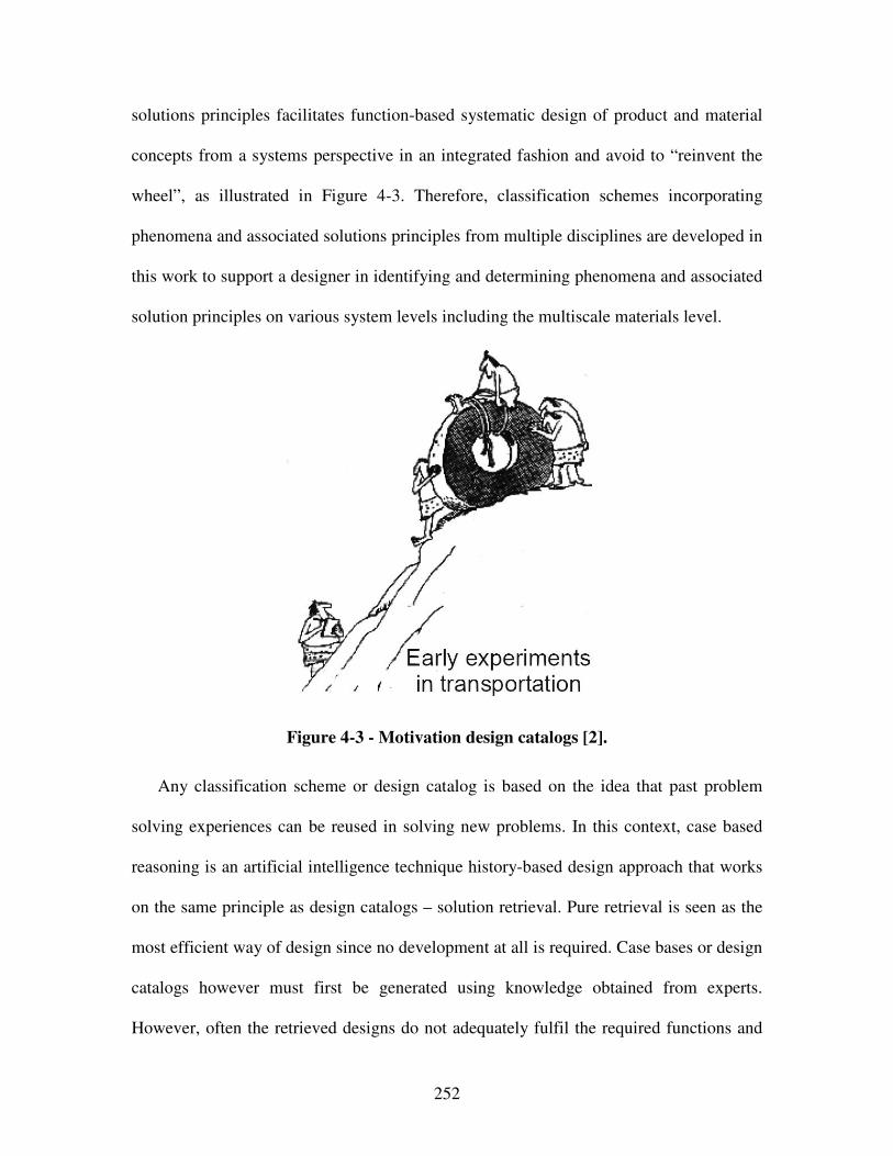
252
solutions principles facilitates function-based systematic design of product and material
concepts from a systems perspective in an integrated fashion and avoid to “reinvent the
wheel”, as illustrated in Figure 4-3. Therefore, classification schemes incorporating
phenomena and associated solutions principles from multiple disciplines are developed in
this work to support a designer in identifying and determining phenomena and associated
solution principles on various system levels including the multiscale materials level.
Figure 4-3 - Motivation design catalogs [2].
Any classification scheme or design catalog is based on the idea that past problem
solving experiences can be reused in solving new problems. In this context, case based
reasoning is an artificial intelligence technique history-based design approach that works
on the same principle as design catalogs – solution retrieval. Pure retrieval is seen as the
most efficient way of design since no development at all is required. Case bases or design
catalogs however must first be generated using knowledge obtained from experts.
However, often the retrieved designs do not adequately fulfil the required functions and
253
need modification. But, once an initial design is retrieved for a given function, it can be
used as a starting point for adaptation, further modifications, or generating other
solutions. Hence, both design catalogs or case based reasoning are well-known concept
generation aids to overcome bounds on human rationality, as discussed in the following.
The theoretical foundations on which the development of history-based design
approaches such as design catalogs is based are reviewed in Section 4.2.1, based on the
nearly inarguable concept of bounded rationality and cognitive science. Then, research
efforts in case-based reasoning and the development of classification or design catalogs
are reviewed in Sections 4.2.2 and 4.2.3. Research gaps are derived and summarized in
Section 4.2.4.
4.2.1 Bounded Rationality
Bounded rationality refers to the notion that there are limits to the powers of human
cognition. It has been shown that humans are endowed with specific and limited
cognitive structures that constrain their behavior as searchers or representors of problem
spaces [734]. Applying bounded rationality to conceptual materials design, it becomes
clearly evident that design decisions cannot encompass all materials variables and instead
should focus on phenomena and associated solution principles that cause a certain
behavior and thereby provide solutions for a variety of problems or cases. Within the
function-based systematic approach, design catalogs for phenomena and associated
254
solution principles can thus be used to facilitate conceptual materials design in the
context of bounded rationality. Phenomena and associated solution principles can thus
help designers as “creatures of bounded rationality incapable of dealing with the world in
all of its complexity to form simplified pictures of the world” [596].
The foundations of bounded rationality have been established by Simon [594] and
reviewed in detail in the work of Peplinski [499]. The concept of bounded rationality
refers to the actual state of the world in which information is uncertain and incomplete,
situations are overwhelmingly complex, and the number of potential courses of action is
nearly infinite. According to Simon [594], an individual is thus limited i) by unconscious
skills, habits, and reflexes, ii) by values and conceptions of purpose, and iii) by the extent
of his knowledge of information. This implies for infinite materials design spaces that
building unified and encompassing models that capture all materials aspects and variables
or incorporate an infinite number of cases or material artifacts can only be imperfectly
achieved. Thus, design catalogs embodied as open-ended maps focused on structure-
property relations that have effects on macroscales are indeed promising tools to facilitate
function-based systematic conceptual materials design from the perspective of bounded
rationality.
The concept of bounded rationality also appears in the design synthesis and cognitive
science literature. As argued by Senge [584]: “Evidence is overwhelming that human
beings have “cognitive limitations”. Cognitive scientists have shown that we can deal
only with a very small number of separate variables simultaneously. Our conscious
information processing short-term memory circuits get easily overloaded by detail
complexity, forcing us to invoke simplifying heuristics to figure things out.”.
255
Furthermore, Heim and Compton argue [259]: “This lack of emphasis on system issues
[in manufacturing enterprises or equivalently material systems] is not the result of a lack
of appreciation for the importance of the problem. Rather, anyone attempting to address
these system issues is immediately confronted by the overwhelming complexity of the
problem”. Hence, having open-ended maps focused on structure-property relations or
phenomena and solution-principles as building blocks to facilitate function-based
systematic conceptual materials design is crucial in complex systems design.
Also, with respect to how human memory works, design catalogs reduce the natural
human forgetting process by enhanced repetition, in other words memory
reestablishment. Especially human working memory – referring to the structures and
processes used for temporarily storing and manipulating information – is limited to a few
pieces of information that can be manipulated at a time [314, 425, 670]. Design catalogs
can thus support a designer’s working memory and thereby facilitate function-based
systematic design of products and material concepts in an integrated fashion.
Whereas a designer’s intuition and expertise may be sufficient from time to time, a
classified collection of knowledge is generally required, especially for the systematic
approach to conceptual materials design developed in Chapter 3. Function-based
systematic conceptual design is based on functional analysis, abstraction, synthesis, and
systematic variation as well as systematic design mappings. Leveraging design catalogs
to classify and store knowledge for easy retrieval, has shown to facilitate systematic
design mappings and lead to time savings of 8 to 15 % during the design-process [551].
Also, systematic presentation of information is helpful to stimulate the search for further
256
solutions in various directions and to facilitates the identification and combination of
essential solution characteristics.
No matter how fast the computer, if it must search for an optimum property using
accurate analysis models of an infinite number of materials, it will still require infinite
time to perform the search. Bottom-up analysis is not design. The key to materials design
is an interplay of multiscale modeling with human decision-making. Hence, with respect
to systematic conceptual materials design, the focus in this work is on developing design
catalogs that enable a designer to identify structure-property relations (in the materials’
language) – in other words identifying underlying phenomena and associated solution
principles that cause a certain behavior and thereby provide solutions for a variety of
problems or cases (in a design language). The idea to facilitate function-based systematic
conceptual materials design in this dissertation is to focus on phenomena and associated
solution principles but not an infinite number of cases or material artifacts, thereby
enabling a designer to step out of the technological cycle of obsolescence and evolution.
Having discussed bounds on human rationality, research efforts in case-based
reasoning and the development of classification or design catalogs are reviewed in
Sections 4.2.2 and 4.2.3. Research gaps are derived and summarized in Section 4.2.4.
257
4.2.2 Case-Based Reasoning
In case based reasoning, previous experiences are stored as cases in a case base. A
case contains information about a problem encountered in the past and a complete and
successful solution to the problem. Given a problem to be solved, solutions to similar
problems encountered in the past are represented and retrieved from memory during case
based reasoning, these previous solutions are adapted to the current problem, and the new
problem and associated solution is stored as another case in the memory [334]. In
summary, case-based reasoning involves three main areas: case representation, retrieval,
and adaptation. Case based reasoning has been used in a variety of domains, such as
architectural design [168], structural design [383], and mechanical design [236]. The
approach has also been widely used in variant design. Examples of these can be found in
work by Fowler [213], and Sycara and Navinchandra [647] for retrieved design, Wood
and Agogino [731] for cases based on customer requirements and life cycle aspects of a
design, Faltings and Sun [196] for innovative mechanism shape design, Rivard and
Fenves [545] for various initial potential solutions, Potter et al. [508] for fluid power
circuit design, Galletti and Giannotti [226] and McGarva [415] for trial-and-error-based
interactive selection of mechanisms from catalogs, or Ong and Guo [461] for web-based
design reuse from concept generation to detailed design.
Dealing with extensive case-based reasoning repositories requires computing systems
to carry out searches efficiently in an effectively represented design space. For example,
Campbell et al. [88] have presented a search strategy in which a multitude of agents are
responsible for the same design task, but represent different strategies and differing
knowledge for solving the design problem. Qiu et al. [520] have presented another
258
system that automatically generates feasible conceptual designs based on the use of
genetic algorithms for searching the solution space. Eckert et al. [176] discuss various
ways in which interactivity can be incorporated into an automated design generation
system to aid a designer in the generation of concepts. Other work in including
interactivity in automated concept generation includes that of Parmee and Bonham [490],
Parmee et al. [491], Parmee [492], and Cvetkovic and Parmee [146]. They describe a
series of efforts in using interactive evolutionary search for supporting design exploration
in conceptual design. The motivation behind their work is the poor definition and
uncertainty during conceptual design. As more information is gained on the design
problem, it requires a redefinition of the problem. However, Wang and Terpenny [706]
also present the use of an interactive evolutionary search approach to synthesise
component based preliminary designs.
An issue of consideration in the development of computing systems to aid solution
generation is the generation of too many concepts so that it becomes difficult or
impossible to evaluate the solutions generated. Therefore, as an alternative to traditional
models of initially generating as many solutions as possible and then converging to a
final single solution, Liu et al. [376] propose a multiple divergent-convergent approach to
the number of concepts generated by a computing system. However, knowledge of what
changes can be made to a design case without perturbing its functions, called adaptation
knowledge, must be provided for evaluating solutions and converging to a final solution.
But, this adaptation is difficult to capture. Moreover, in any case-based reasoning tool,
knowledge is tied only into an account of its properties and specifications and a
description of it’s current application or past cases.
259
4.2.3 Classification Schemes and Design Catalogs
Classification schemes, providing a classified collection of known and proven
solutions for easy retrieval or stimulation, are referred to as design catalogs in the design
literature. In general, classification schemes are characterized by systematic presentation
of information. Systematic presentation of information is helpful in two respects. On the
one hand it stimulates the search for further solutions in various directions; on the other
hand it facilitates the identification and combination of essential solution characteristics.
Similarly, design catalogs represent knowledge storage outside human memory in
classified form. They consist of problem-independent classifying criteria, solution
characteristics, and selection characteristics. The purpose of design catalogs is to obtain
an overview of a certain domain or subarea that is as complete as possible.
The usual two-dimensional classification scheme consists of rows and columns of
parameters used as classifying criteria. The choice of classifying criteria or their
parameters is of crucial importance. However, classification schemes providing a
classified collection of knowledge are a condition precedent for design. Whereas a
designer’s expertise and internal knowledge base may be sufficient from time to time, a
classified collection of knowledge is generally required, especially for systematic design.
Systematic design processes may only become independent of a designer’s internal
knowledge base and in the limit become reproducible if knowledge is classified and
stored for easy retrieval by other designers, leading to time savings of 8 to 15 % during
the design-process [551].
Classification schemes providing a classified collection of known and proven
solutions for easy retrieval or stimulation can serve as design catalogues during all phases
260
of the search for a solution – from clarification of task to conceptual, embodiment and
detail design. They can also help in the combination of subsolutions into overall
solutions. Zwicky [773] has referred to them as morphological matrices during a solution
finding process. In general though, design catalogues are collections of known or proven
solutions [470]. They contain data of various types and solutions at distinct levels of
embodiment. Hence, design catalogues should provide:
• knowledge and experiences of different designers is captured in a single location,
• quicker, more problem-oriented access to the accumulated solutions or data,
• self-explanatory classification for easy retrieval,
• a comprehensive range of possible solutions or at the very least the most essential
ones which can be extended later, and
• the greatest possible range of interdisciplinary applications.
In general, classifying criteria determine the structure of a design catalog. Classifying
criteria can be solutions or solution characteristics. Depending on the level of abstraction,
solutions are represented as sketches, with or without physical equations. Solution
characteristics however are important for the choice of solutions. They may involve a
great variety of properties (e.g., typical dimensions, reliability, responses, number of
elements, etc.), helping designers in the preliminary selection and evaluation of solutions.
A remark section in the design catalog typically provides information about the origin of
the data and for additional comments.
Design catalogs on various levels of abstraction have been widely used in conceptual
systems design. General guidelines about the construction of catalogs and a list of
available catalogs and solutions has been reviewed by Roth [552]. Design catalogs
261
containing physical effects and solutions to prominent functional relationships on the
systems level have been developed by Koller [332]. As reviewed in detail by Pahl and
Beitz [470], design catalogs with respect to various types of connections, guides and
bearings, power generation and transmission, kinematics and mechanisms, gearboxes,
safety technology, ergonomics, as well as production processes, have been developed by
Roth [552], Ewald [193], Wölse and Kastner [727], Kopowski [336], Grandt [239],
Fuhrmann and Hinterwalder [221], Ersoy [189], Gießner [233], Diekhöner and Lohkamp
[166] and [165], Kollmann [333], Jung and Schneider [313, 571], Raab and Schneider
[523], as well as Neudörfer [449-451]. Also, design catalogs focused on the
representation and abstraction of known structural elements to generate concepts have
been addressed in the work of Chakrabarti and Bligh [95-97]. However, classification
schemes or design catalogs to facilitate a function-based, systematic approach to the
integrated design of product and material concepts have not yet been addressed.
4.2.4 Research Gap Analysis Case-Based Reasoning and Design Catalogs
As motivated in Section 1.1 and illustrated in Section 4.3, potential technological
breakthroughs are likely to be achieved when leveraging the potential embedded in
materials design and concurrently design products and materials, thereby overcoming the
property and performance limitation of materials available to designers through materials
selection approaches. Materials scientists on the other hand facilitate materials design by
creating increasingly sophisticated and accurate physics-based models, embodying
262
processing-structure-property relationships of materials. In this work, the focus is on
increasing a designer’s concept flexibility, i.e., ability to explore design options with
ease, and increasing a designer’s design-process flexibility, i.e, ability to manage
complexity, in order facilitate integrated product and materials design.
In Table 2-4, it is noted that multiscale modeling of materials is simply an element or
tool that may be employed in materials design, but does not in itself comprise materials
design. In fact, concurrent multiscale modeling typically has distinct objectives of
predicting response of structures or devices with accuracy in applications rather than
facilitating tailoring of materials to satisfy macroscale performance requirements. As
argued by Eberhart and Clougherty [175], no matter how fast the computer, if it must
search for an optimum property using accurate analysis models of an infinite number of
materials, it will still require infinite time to perform the search. Hence, the viewpoint of
materials design as an automated search exercise is very limited. Also, scientific, mostly
complex multiscale models might not be necessary in many cases because the goal of
materials is not to accurately predict material properties but to satisfy performance
requirements.
Bottom-up analysis is not design. The key to materials design is an interplay of
multiscale modeling with human decision-making. Hence, materials design must begin
with a set of performance requirements that map to materials properties. Then, it is
advantageous to identify a finite set of candidate material concepts that are likely to
possess these properties. As pointed out by Eberhart and Clougherty [175], this is most
efficient when constructing structure-property relations on the quantum scale and then
study these materials experimentally, thereby turning computational empiricism into true
263
design. The focus in this work is to identify and classify structure-property relations on
multiple length scales to facilitate the design of material concepts to be further
investigated through systems-based embodiment materials design, in line with Smith’s
observation that structure is best considered as a hierarchy, with each of its levels
characterized by a different length scale [610]. Process-structure relations refer more to
materials development and hence are not further considered. In this dissertation, the goal
is to increase a designer’s concept flexibility through leveraging structure-property
relations.
The way turbulence controls the efficiency of an object moving through a fluid is an
example of a structure-property relationship and has been illustrated by Eberhart and
Clougherty [175]. Consider turbulence as a structure that gives rise to drag, a property. In
this context, identifying the source of turbulence provides the most efficient way to
decrease drag. Calculating the drag coefficient through accurate multiscale modeling
however does not give a designer insight into the causes of drag. Hence, rather than
calculating the drag coefficient, observing the flow field in a wind tunnel or working
directly with a computationally determined flow filed is advantageous to a designer.
However, as Eberhart and Clougherty [175] state, structure-property relations, like
turbulence-drag, form the basis for materials design – a designer’s ability to design
materials is limited by incomplete knowledge and interpretation of the structure-property
relationships governing the behaviors of materials.
Also, from a mathematical viewpoint, all equations of physics (microscopic and
macroscopic) are relevant for designing materials. In an absolutely strict theoretical way,
a designer would have to proceed from the fundamentals of quantum field theory and
264
write down the ~1023 coupled equations for all the atoms in a material. Then, those would
have to be solved including the complicated geometrical boundary conditions during the
course of designing. Realistically however, it is crucial to focus efforts on phenomena
and associated solution principles that drive a certain behavior and neglect irrelevant
relativistic effects, even when embodying specific material systems.
With respect to systematic conceptual materials design, what is required in essence is
an open-ended map that enables a designer to identify structure-property relationships (in
the materials’ language) – in other words identifying underlying phenomena and
associated solution principles that cause a certain behavior and thereby provide solutions
for a variety of problems or cases (in a design language). The idea to facilitate systematic
conceptual materials design in this dissertation is to focus on phenomena and associated
solution principles but not an infinite number of cases or material artifacts, thereby
enabling a designer to step out of the technological cycle of obsolescence and evolution.
Operating at the level of phenomena and associated solution principles requires a
much more active engagement by the designer than do the typical selection approaches.
However, if knowledge of a material/system is tied only into an account of its
properties/specifications and a description of its current application or past cases, then
that knowledge may become obsolete along with the material/system quickly. By
operating at the level of phenomena and associated solution principles, a particular
material/system at any given time is only illustrative of the possibilities, not their
determinant. As materials/systems cycle through evolution and obsolescence, the
questions that are raised by their uses should remain. Hence, it is crucial to identify and
determine phenomena and associated solution principles to design and develop product
265
and material concepts that have a dynamic behavior in an integrated fashion from a
systems perspective.
In the design literature, phenomena are also labeled physical effects, chemical effects,
etc. These effects have therefore been classified in terms of the discipline from which
they are derived, such as mechanical engineering. Physical effects for the specific
domains of mechanical and electrical engineering have already been classified by Koller
[332], Clausen and Rodenacker [138] as well as Roth [552]. A few chemical effects are
summarized by Orloff [462]. Also, focus of existing design catalogs has so far been on
mechanical engineering domain-specific applications, such as connections, guides and
bearings, power generation and transmission, kinematics, gearboxes, safety technology,
ergonomics as well as production processes. Furthermore, design catalogs and
classification schemes have only been organized in terms of generally valid functions of
the product domain. Limitations of research efforts with respect to developing
classification schemes, design catalogs or case-based reasoning techniques are
summarized in Table 1-5.
Multidisciplinary integrated materials and product design efforts involving
phenomena and associated solution principles have not been addressed. So far, solution
principles embodying a specific phenomenon have only been addressed for the product
domain from a macro-level perspective, not considering the potential embedded in
materials design on multiple scales. For effective and efficient integrated design of
product and material concepts it is crucial to identify materials phenomena and associated
governing solution principles, i.e, property-structure relations, in addition to macro-level
product specific physical effects that can be found in the literature.
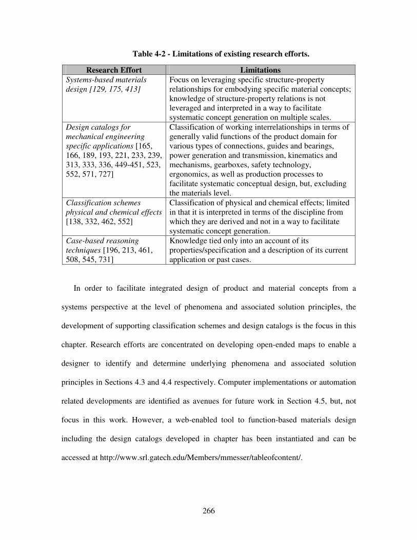
266
Table 4-2 - Limitations of existing research efforts.
Research Effort Limitations
Systems-based materials
design [129, 175, 413]
Focus on leveraging specific structure-property relationships for embodying specific material concepts; knowledge of structure-property relations is not leveraged and interpreted in a way to facilitate systematic concept generation on multiple scales.
Design catalogs for
mechanical engineering
specific applications [165, 166, 189, 193, 221, 233, 239, 313, 333, 336, 449-451, 523, 552, 571, 727]
Classification of working interrelationships in terms of generally valid functions of the product domain for various types of connections, guides and bearings, power generation and transmission, kinematics and mechanisms, gearboxes, safety technology, ergonomics, as well as production processes to facilitate systematic conceptual design, but, excluding the materials level.
Classification schemes
physical and chemical effects
[138, 332, 462, 552]
Classification of physical and chemical effects; limited in that it is interpreted in terms of the discipline from which they are derived and not in a way to facilitate systematic concept generation.
Case-based reasoning
techniques [196, 213, 461, 508, 545, 731]
Knowledge tied only into an account of its properties/specification and a description of its current application or past cases.
In order to facilitate integrated design of product and material concepts from a
systems perspective at the level of phenomena and associated solution principles, the
development of supporting classification schemes and design catalogs is the focus in this
chapter. Research efforts are concentrated on developing open-ended maps to enable a
designer to identify and determine underlying phenomena and associated solution
principles in Sections 4.3 and 4.4 respectively. Computer implementations or automation
related developments are identified as avenues for future work in Section 4.5, but, not
focus in this work. However, a web-enabled tool to function-based materials design
including the design catalogs developed in chapter has been instantiated and can be
accessed at http://www.srl.gatech.edu/Members/mmesser/tableofcontent/.
267
4.3 Design Catalog – Phenomena
Phenomena are described quantitatively by means of laws governing the quantities
involved. In other words, phenomena can be described by the laws of physics and
mathematics. For example, the operation of a bi-metallic strip is the result of a
combination of two phenomena, namely thermal expansion and elasticity. A sub-function
can often be fulfilled by one of a number of phenomena. For example, a force can be
amplified by the mechanical lever phenomenon, fluid-mechanical hydraulic lever
phenomenon, or electromagnetic phenomena. In this work, focus is on developing
classification schemes for integrated product and materials design, providing phenomena
and associated solution principles for embodying the most prominent functional
relationships of changing, storing and transforming energy. These generally valid
functional relationships are chosen to support eliciting and providing the most product-
independent solutions.
Since energy change, storage and transformation phenomena are governed by
underlying energy forms, mechanical, pneumatical/hydraulic, electrostatic,
magnetostatic, sound, light, thermal as well as chemical, biological and nuclear forms of
energy are used as classifying criteria. Considering these forms of energy as system in-
and out-puts, phenomena are classified in Table 4-3. Since whenever an entity – from an
atom to an ecosystem – undergoes any kind of change, energy must transfer and/or
change energy form, this energy-based classification scheme captures the majority of
phenomena at a designer’s disposal. In essence, this open-ended classification of
phenomena is intended to support a designer in identifying underlying phenomena that
may lead to generating and designing novel concepts from a systems perspective on
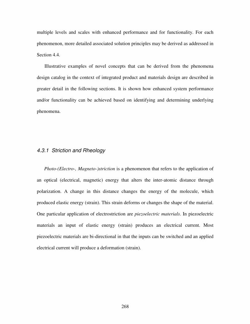
268
multiple levels and scales with enhanced performance and for functionality. For each
phenomenon, more detailed associated solution principles may be derived as addressed in
Section 4.4.
Illustrative examples of novel concepts that can be derived from the phenomena
design catalog in the context of integrated product and materials design are described in
greater detail in the following sections. It is shown how enhanced system performance
and/or functionality can be achieved based on identifying and determining underlying
phenomena.
4.3.1 Striction and Rheology
Photo-(Electro-, Magneto-)striction is a phenomenon that refers to the application of
an optical (electrical, magnetic) energy that alters the inter-atomic distance through
polarization. A change in this distance changes the energy of the molecule, which
produced elastic energy (strain). This strain deforms or changes the shape of the material.
One particular application of electrostriction are piezoelectric materials. In piezoelectric
materials an input of elastic energy (strain) produces an electrical current. Most
piezoelectric materials are bi-directional in that the inputs can be switched and an applied
electrical current will produce a deformation (strain).
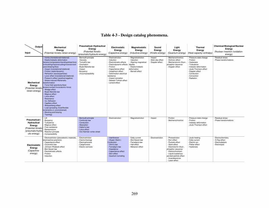
269
Table 4-3 - Design catalog phenomena.
Mechanical
Energy
(Potential-/kinetic-/strain-energy)
Output
Input
Thermal
Energy
(Heat-capacity/-enthalpy)
Chemical/Biological/Nuclear
Energy
(Nuclear-/reaction-/oxidation-
energy)
Electrostatic
Energy
(Capacitive-energy)
Magnetostatic
Energy
(Inductive-energy)
Sound
Energy
(Kinetic-energy)
Light
Energy
(Quantum-energy)
Pneumatical-/Hydraulical
Energy
(Potential-/kinetic-
/pneumatic/hydraulic-energy) - Inertia (translational/rotational)
- Elastic/inelastic deformation
(tension/compression/bending/shear/torsi
on/buckling/fracture/cutting/inversion/extr
usion/drawing/flow)
- Impact (translational/rotational)
- Friction (static/dynamic)
- Refraction (waves/particles)
- Lever-effect (translational/rotational)
- Poisson's-effect (positive/negative)
- Stress-induced Martensitic
transformation
- Force field (gravity/surface-
tension/contact-force/atomic-force)
- Wedge-effect
- Boyle-Mariotte-law
- Magnus-effect
- Lotus-effect
- Resonance
- Co-/Adhesion
- Capillary-effect
- Weissenberg-effect
- Load spreading (fixed/flexible
constraints or unconstrained)
- Blocking and bracing
- Topology
- Bernoulli-principle
- Viscosity
- Toricelli's law
- Gravitation
- Boyle-Mariotte-law
- Impact
- Buoyancy
- (In)compressibility
- Electrostriction
- Induction
- Electrokinetic-effects
- Electrodynamic-effects
- Friction
- Capacitance-effect
- Josephson-effect
- Deformation electrical
resistance
- Impact-ionization
- Stewart-Tolman-effect
- Lenard-effect
- Magnetostriction
- Induction
- Aligning magnetical
dipoles
- Elastic/inelastic
deformation
- Barnett-effect
- Impact
- Stick-slip-effect
- Doppler-effect
- Mechanochromics
- Dichroic-effect
- Mechanolumin-(fluor-,
phosphor-)escence
- Doppler-effect
- Pressure state change
- Friction
- Hysteresis
- Turbulence
- Inelastic deformation
- Joule-Thomson-effect
- Doppler-effect
- Conduction
- Convection
- Radiation
- Residual stress
- Phase transformations
- Lift
- Buoyancy
- Turbulence
- Magnus-effect
- Flow resistance
- Backpressure
- Reaction principle
- Compressibility
- Bernoulli-principle
- Continuity-law
- Conduction
- Absorption
- Dalton's-law
- Lotus-effect
- Von Kármán vortex street
- Electrostriction - Magnetostriction - Impact - Friction
- Mechanochromics
- Pressure state change
- Friction
- Inelastic deformation
- Joule-Thomson-effect
- Residual stress
- Phase transformations
- Electrostriction (piezoelectric materials,
electroactive polymers)
- Capacitance effect
- Coulomb's-law
- Johnson-Rhabeck-effect
- Biot-Savart-law
- Electrokinetic-effects
- Friction
- Induction
- Electrostriction
- Electrorheology
- Electrophoresis
- Cataphoresis
- Electro-osmosis
- Interference
- (Super-/Semi-)
Conduction
- Ohm's-law
- Farraday's-law
- Impedance
- Capacitance-effect
- Skin-effect
- Quantum tunneling
- Eddy current
- Biot-Savart-law
- Farraday's-law
- Hall-effect
- Meissner-effect
- Electrostriction - Photostriction
- Kerr-effect
- Pockels-effect
- Stark-effect
- Electrolumin-(fluor-,
phosphor-)escence
- Electrochromism
- Liquid-crystal/sus-
pended-particle effect
- Incandescence
- Laser-effect
- Joule-heating
- Eddy current
- Electric arc
- Peltier-effect
- Hysteresis
- Electrochemistry
- X-Ray-effect
- Electrodialysis
- Electrolysis
Mechanical
Energy
(Potential-/kinetic-
/strain-energy)
Electrostatic
Energy
(Capacitive-
energy)
Pneumatical-/
Hydraulical
Energy
(Potential-/kinetic-
/pneumatic/hydra
ulic-energy)
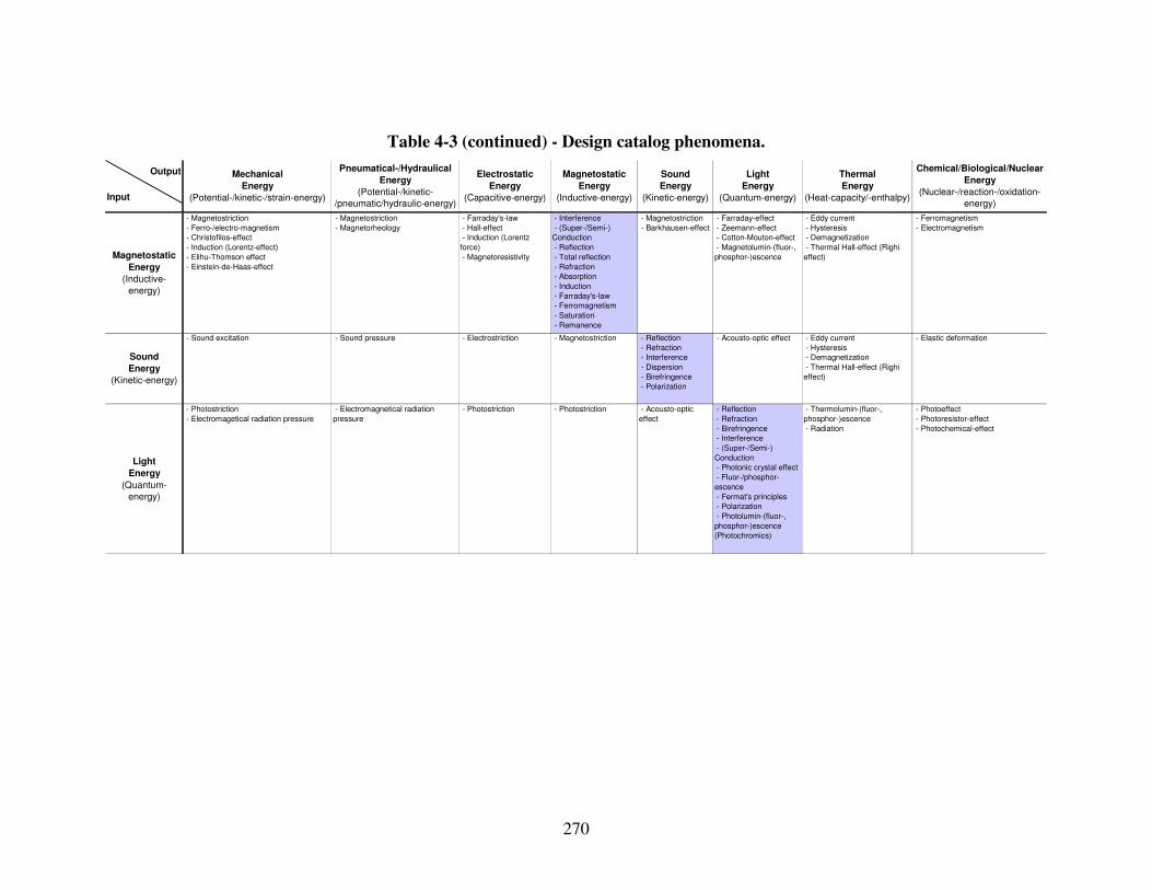
270
Table 4-3 (continued) - Design catalog phenomena.
Mechanical
Energy
(Potential-/kinetic-/strain-energy)
Output
Input
Thermal
Energy
(Heat-capacity/-enthalpy)
Chemical/Biological/Nuclear
Energy
(Nuclear-/reaction-/oxidation-
energy)
Electrostatic
Energy
(Capacitive-energy)
Magnetostatic
Energy
(Inductive-energy)
Sound
Energy
(Kinetic-energy)
Light
Energy
(Quantum-energy)
Pneumatical-/Hydraulical
Energy
(Potential-/kinetic-
/pneumatic/hydraulic-energy) - Magnetostriction
- Ferro-/electro-magnetism
- Christofilos-effect
- Induction (Lorentz-effect)
- Elihu-Thomson effect
- Einstein-de-Haas-effect
- Magnetostriction
- Magnetorheology
- Farraday's-law
- Hall-effect
- Induction (Lorentz
force)
- Magnetoresistivity
- Interference
- (Super-/Semi-)
Conduction
- Reflection
- Total reflection
- Refraction
- Absorption
- Induction
- Farraday's-law
- Ferromagnetism
- Saturation
- Remanence
- Magnetostriction
- Barkhausen-effect
- Farraday-effect
- Zeemann-effect
- Cotton-Mouton-effect
- Magnetolumin-(fluor-,
phosphor-)escence
- Eddy current
- Hysteresis
- Demagnetization
- Thermal Hall-effect (Righi
effect)
- Ferromagnetism
- Electromagnetism
- Sound excitation - Sound pressure - Electrostriction - Magnetostriction - Reflection
- Refraction
- Interference
- Dispersion
- Birefringence
- Polarization
- Acousto-optic effect - Eddy current
- Hysteresis
- Demagnetization
- Thermal Hall-effect (Righi
effect)
- Elastic deformation
- Photostriction
- Electromagetical radiation pressure
- Electromagnetical radiation
pressure
- Photostriction - Photostriction - Acousto-optic
effect
- Reflection
- Refraction
- Birefringence
- Interference
- (Super-/Semi-)
Conduction
- Photonic crystal effect
- Fluor-/phosphor-
escence
- Fermat's principles
- Polarization
- Photolumin-(fluor-,
phosphor-)escence
(Photochromics)
- Thermolumin-(fluor-,
phosphor-)escence
- Radiation
- Photoeffect
- Photoresistor-effect
- Photochemical-effect
Magnetostatic
Energy
(Inductive-
energy)
Sound
Energy
(Kinetic-energy)
Light
Energy
(Quantum-
energy)
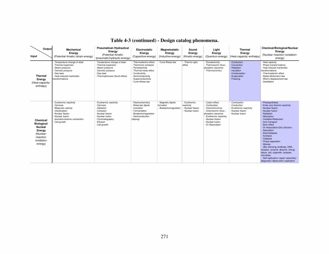
271
Table 4-3 (continued) - Design catalog phenomena.
Mechanical
Energy
(Potential-/kinetic-/strain-energy)
Output
Input
Thermal
Energy
(Heat-capacity/-enthalpy)
Chemical/Biological/Nuclear
Energy
(Nuclear-/reaction-/oxidation-
energy)
Electrostatic
Energy
(Capacitive-energy)
Magnetostatic
Energy
(Inductive-energy)
Sound
Energy
(Kinetic-energy)
Light
Energy
(Quantum-energy)
Pneumatical-/Hydraulical
Energy
(Potential-/kinetic-
/pneumatic/hydraulic-energy) - Temperature change of state
- Thermal expansion
- Steam pressure
- Osmotic pressure
- Gas laws
- Heat-induced martensitic
transformations
- Temperature change of state
- Thermal expansion
- Steam pressure
- Osmotic pressure
- Gas laws
- Thermophoresis (Soret-effect)
- Thermoelectric-effect
- Thermionic emission
- Pyroelectricity
- Thermal-noise-effect
- Conductivity
- Semiconductivity
- Superconductivity
- Curie-Weiss-law
- Curie-Weiss-law - Thermo-optic
effect
- Pyroelectricity
- Thermolumin-(fluor-,
phosphor-)escence
- Thermocromics
- Conduction
- Convection
- Radiation
- Insulation
- Condensation
- Evaporation
- Freezing
- Heat capacity
- Phase transformations
- Heat induced martensitic
transformations
- Thermoelectric effect
- Stefan-Boltzmann-law
- Wien's displacement-law
- Destillation
- Exothermic reactivity
- Osmosis
- Molecular-velocity
- (De)Sorption
- Nuclear fission
- Nuclear fusion
- Isometric/isotonic contraction
- Cell growth
- Exothermic reactivity
- Osmosis
- Adhesion
- Cohesion
- Nuclear fission
- Nuclear fusion
- Chromatography
- Effusion
- Cell growth
- Electrochemistry
- Molecular dipole
- Ionization
- Fermentation
- Bioelectromagnetism
- Semiconduction
(doping)
- Magnetic-dipole-
formation
- Bioelectromagnetism
- Exothermic
reactivity
- Nuclear fission
- Nuclear fusion
- Cotton-effect
- Combustion
- Chemochromics
- Chemolumin-(fluor-,
phosphor-)escence
- Exothermic reactivity
- Nuclear fission
- Nuclear fusion
- Di-/Association
- Combustion
- Conduction
- Exothermic reactivity
- Nuclear fission
- Nuclear fusion
- Photosynthesis
- Endo-/exo-thermic reactivity
- Nuclear fission
- Nuclear fusion
- Radiation
- Absorption
- Oxidation/Reduction
- Ionic transport
- Bohr-effect
- Di-/Association/(Dis-)Solution
- Adsorption
- Electrodialysis
- Autolysis
- Catalysis
- Phase separation
- Meiosis
- (Bio-)Sensing (antibody, DNA,
receptor, enzyme, abzyme, (living)
tissue, cell, organelle, isotopes,
microbes)
- Self-replication/-repair/-assembly/-
diagnostic/-destruction/-replication
Thermal
Energy
(Heat-capacity/-
enthalpy)
Chemical/
Biological/
Nuclear
Energy
(Nuclear-
/reaction-
/oxidation-
energy)
272
The piezoelectric effect forms the underlying basis for products as diverse as some
types of microphones and speakers or even motors as illustrated in Figure 4-4 b). Also,
charcoal grill fire starters, vibration reducing skis, doorbell pushers and an endless
number of position sensors and small actuators are derived from this phenomenon.
Photoactuators for example are used in power plants and other commercial and scientific
areas such as light-source chasing for devices that would follow light sources. Another
interesting example are Zinc oxide nannowires that produce an electrocal current and
omit light from applied strain as shown in Figure 4-4 a).
Another particular example of electrostriction is a new class of acrylic-based
polymers, i.e., electro-elastomers, exhibiting phenomenal strains under the influence of
applied voltages, far exceeding the performance of piezoelectric or shape-memory
materials [135]. An important feature of these elctro-active elastomers is that they may be
used in reverse, i.e., when compressed they generate a signal (electric field) and can
hence be used for sensor applications. Proposed applications for these electro-elastomers
include loudspeaker diaphragms, devices for noise cancellation, unusual types of motors
and pumps, etc. as well as multifunctional elctro-elastomer rolls that consist of polymer
sheets and suitable flexible electrodes rolled into tubes.
Magneto-(Electro-)rheology is a phenomenon that refers to the application of a(n)
magnetic field (electric field) which causes a change in micro-structural orientation,
resulting in a change in viscosity of the fluid. The changes in viscosity when
electrorheological or magnetorhelogogical fluids are exposed to electric or magnetic
fields, respectively, can be startling. A liquid is seemingly transformed into a solid and
back again to a liquid as the field is turned off and on. An electrorheological fluid
273
embedded in an automobile tire, for example, can cause the stiffness of the tire to change
upon demand; thus making it possible to tune tires for better cornering or more
comfortable straight riding. One can also imagine dampers, chairs or beds with smart
rheological fluids embedded so that the relative hardness or softness could be electrically
adjusted. However, magneto-(electro-)rheology can also be leveraged to design sculptural
pieces, as done by Sachiko Kodama [331] through the use of ferro fluid shown in Figure
4-4 c).
a)
b)
c)
Figure 4-4 - a) Zinc oxide nanowires [707], b) ultrasonic piezoelectronic motor [621],
and c) ferro fluid sculptures [331].
4.3.2 Semi-, and Super-Conductors as well as Meta-Materials
Whereas conductivity generally refers to resistivity, superconductivity refers to a
phenomenon in materials below a certain critical temperature where resistivity almost
vanishes. Superconducting magnets for example revolutionized magnetic resonance
imaging, power transmission, filters for microwave and cellular base stations, and
magnetic field sensor. Semiconductor materials (such as silicon) on the other hand are
neither good conductors nor good insulators, but, with the addition of small impurities
called dopants, they can be tailored to possess many fascinating electrical properties. The
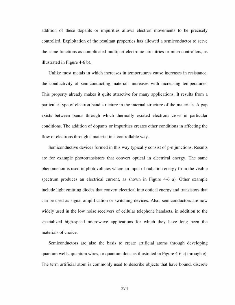
274
addition of these dopants or impurities allows electron movements to be precisely
controlled. Exploitation of the resultant properties has allowed a semiconductor to serve
the same functions as complicated multipart electronic circuitries or microcontrollers, as
illustrated in Figure 4-6 b).
Unlike most metals in which increases in temperatures cause increases in resistance,
the conductivity of semiconducting materials increases with increasing temperatures.
This property already makes it quite attractive for many applications. It results from a
particular type of electron band structure in the internal structure of the materials. A gap
exists between bands through which thermally excited electrons cross in particular
conditions. The addition of dopants or impurities creates other conditions in affecting the
flow of electrons through a material in a controllable way.
Semiconductive devices formed in this way typically consist of p-n junctions. Results
are for example phototransistors that convert optical in electrical energy. The same
phenomenon is used in photovoltaics where an input of radiation energy from the visible
spectrum produces an electrical current, as shown in Figure 4-6 a). Other example
include light emitting diodes that convert electrical into optical energy and transistors that
can be used as signal amplification or switching devices. Also, semiconductors are now
widely used in the low noise receivers of cellular telephone handsets, in addition to the
specialized high-speed microwave applications for which they have long been the
materials of choice.
Semiconductors are also the basis to create artificial atoms through developing
quantum wells, quantum wires, or quantum dots, as illustrated in Figure 4-6 c) through e).
The term artificial atom is commonly used to describe objects that have bound, discrete
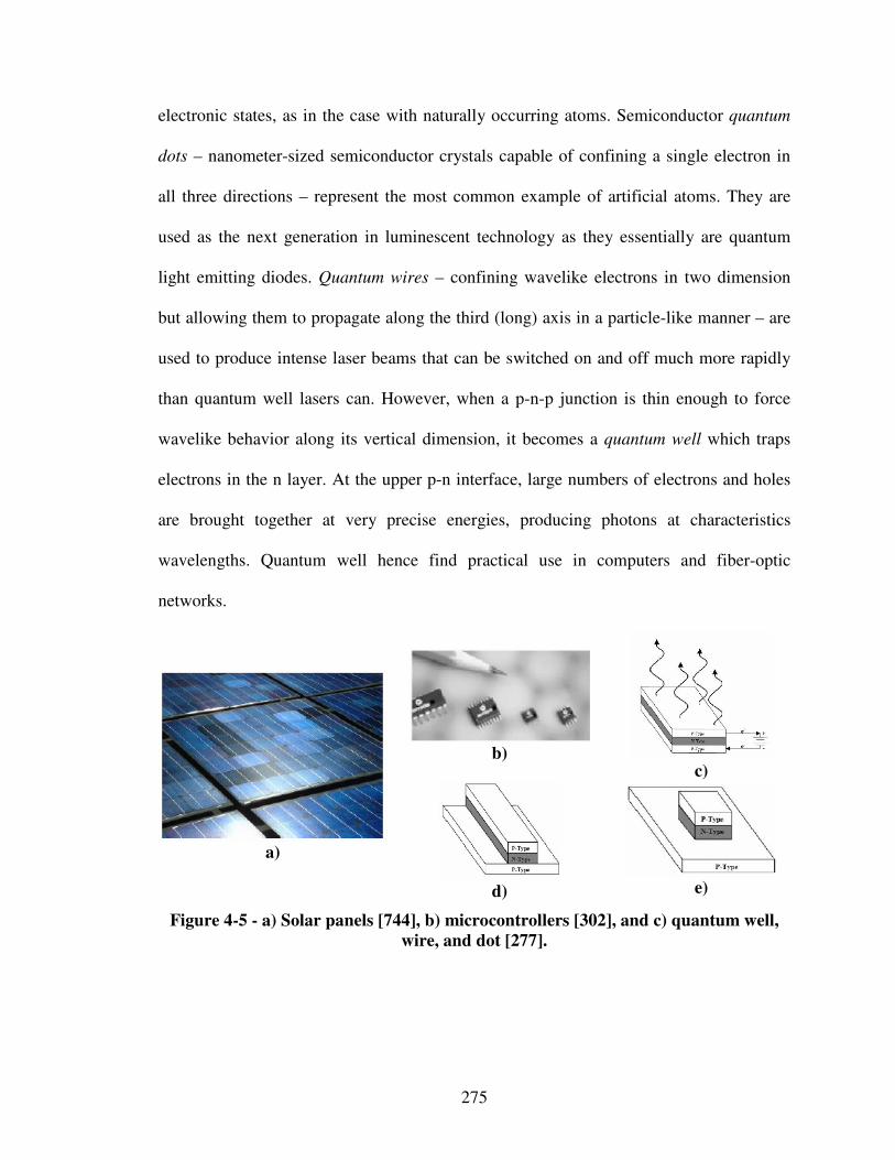
275
electronic states, as in the case with naturally occurring atoms. Semiconductor quantum
dots – nanometer-sized semiconductor crystals capable of confining a single electron in
all three directions – represent the most common example of artificial atoms. They are
used as the next generation in luminescent technology as they essentially are quantum
light emitting diodes. Quantum wires – confining wavelike electrons in two dimension
but allowing them to propagate along the third (long) axis in a particle-like manner – are
used to produce intense laser beams that can be switched on and off much more rapidly
than quantum well lasers can. However, when a p-n-p junction is thin enough to force
wavelike behavior along its vertical dimension, it becomes a quantum well which traps
electrons in the n layer. At the upper p-n interface, large numbers of electrons and holes
are brought together at very precise energies, producing photons at characteristics
wavelengths. Quantum well hence find practical use in computers and fiber-optic
networks.
b)
c)
a)
d)
e)
Figure 4-5 - a) Solar panels [744], b) microcontrollers [302], and c) quantum well,
wire, and dot [277].
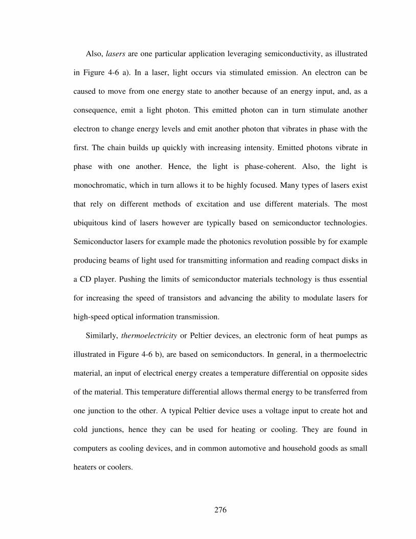
276
Also, lasers are one particular application leveraging semiconductivity, as illustrated
in Figure 4-6 a). In a laser, light occurs via stimulated emission. An electron can be
caused to move from one energy state to another because of an energy input, and, as a
consequence, emit a light photon. This emitted photon can in turn stimulate another
electron to change energy levels and emit another photon that vibrates in phase with the
first. The chain builds up quickly with increasing intensity. Emitted photons vibrate in
phase with one another. Hence, the light is phase-coherent. Also, the light is
monochromatic, which in turn allows it to be highly focused. Many types of lasers exist
that rely on different methods of excitation and use different materials. The most
ubiquitous kind of lasers however are typically based on semiconductor technologies.
Semiconductor lasers for example made the photonics revolution possible by for example
producing beams of light used for transmitting information and reading compact disks in
a CD player. Pushing the limits of semiconductor materials technology is thus essential
for increasing the speed of transistors and advancing the ability to modulate lasers for
high-speed optical information transmission.
Similarly, thermoelectricity or Peltier devices, an electronic form of heat pumps as
illustrated in Figure 4-6 b), are based on semiconductors. In general, in a thermoelectric
material, an input of electrical energy creates a temperature differential on opposite sides
of the material. This temperature differential allows thermal energy to be transferred from
one junction to the other. A typical Peltier device uses a voltage input to create hot and
cold junctions, hence they can be used for heating or cooling. They are found in
computers as cooling devices, and in common automotive and household goods as small
heaters or coolers.

277
Semiconductors are also used in many of today’s biosensensing “materials” where
biological systems are highly adept at molecular recognition. In general, a biosensor is
considered any sensing device that either contains or responds to a biological element.
However, the term biosensor is more appropriately applied to a sensor that contains a
biological element. Examples include enzymes, antibodies, cells, microbes and living
tissues can be used as biosensing “materials” through efficient recognition procedures
[562].
The key requirement in choosing the biological element has to do with its ability to
provide a selective response through binding to the analyte at the expected
concentrations, regardless of the other chemicals that may be present or of an
inhospitable environment. When binding occurs, the biosensing element may respond in
several ways, from conversion to another chemical or release of a chemical, but the most
useful manner is if the response result in a change of one of its electronical or optical
properties. Hence, semiconductors may be used as transducer elements responsible for
converting the element’s response into a measurable signal. The biological element is
deposited on the semiconductor surface and thus electron flow is directly affected when
binding to an analyte occurs [690]. Practical applications are for example the web-based
"Exmocare" Bluetooth-enabled biosensor wristwatch service for augmenting proper
medical supervision of the elderly, as illustrated in Figure 4-6 c). Other applications
include sensing blood glucose levels for diabetics, food process control and inspection,
molecular recognition, etc.
Electromagnetic multifunctional material systems include structural material systems
serving as antennas and transmitters, sometimes referred to as metamaterials or photonic
278
crystals. These systems rely primarily on their feature arrangement or topology to induce
unique electromagnetic properties. Whether used as passive structural members or
structural antennas, transmitters, and/or reflectors, an important attribute of the material is
their interaction with electromagnetic radiation over the entire spectrum. This interaction
is dictated by the way atoms and electrons in the solid interact with the electric and
magnetic field of the wave. More specifically, the incident energy leads to excitation of
electronic and ionic dipoles that, in turn, radiate energy that interferes with the incoming
energy as described by Maxwell’s equations. Thus, electronic diploes determine the
optical properties of solids and ionic dipoles determine the infrared and microwave
properties. A critical parameter that describes this interaction is the permeability which,
along with the permittivity, determines the index of refraction potentially resulting in
desired bandgaps and negative indices of refraction. A fascinating finding is that the
properties arise as a result of the periodic morphological and topological arrangement of
the features rather than their specific composition [282].
a) b) c)
Figure 4-6 - a) lasers [279], b) Peltier device [424], and c) Exmocare Bluetooth-
enabled biosensor wristwatch service for augmenting proper medical supervision of
the elderly [377].

279
4.3.3 Luminescence, Tropism and Chromism
(Electro-, magneto-, photo-, thermo-, chemo-, mechano-, bio-) lumi-(fluor-,
phosphor-)escence is a phenomenon where a material emits light in response to incident
(electrical, magnetical, optical, thermal, chemical, mechanical, biological) energy. The
light is caused by the re-emission of energy in wavelength in the visible spectrum and is
associated with the reversion of electrons from a higher energy state to a lower energy
state. A classic example of a material that is luminescent due to a chemical action is the
well-known chemoluminescent “light-stick”. If the emission of light occurs more or less
instantaneously, the term fluorescence is used. If the emission is slower or delayed to
several microseconds or milliseconds, the term phosphorescence is used. Many
compounds are either naturally phosphorescent or designed to be so. The amount of delay
time depends on the particular kind of phosphor used.
For example, common television screens rely on the use of phosphorescent materials.
Also, typical fluorescent lamps are based on photoluminescent effects where the incident
energy associated with an external light source acts upon a material that then re-emits
light at a lower energy level. However, different properties, including the color of the
emitted light, can be engineered by varying different compounds and impurity inclusions
to yield specific kinds of light-emitting materials. In some situations (afterglow), the light
emission can continue long after the source of excitation is removed – the electrons
become temporarily trapped because of material characteristics. However,
electroluminescent lamps are another application becoming widely used. They draw little
power and generate no heat. They provide a uniformly illuminated surface that appears
equally bright from all angles. Since they do not have moving or delicate parts, they do
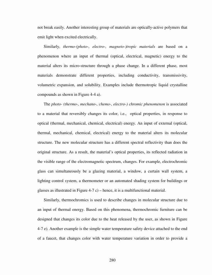
280
not break easily. Another interesting group of materials are optically-active polymers that
emit light when excited electrically.
Similarly, thermo-(photo-, electro-, magneto-)tropic materials are based on a
phenomenon where an input of thermal (optical, electrical, magnetic) energy to the
material alters its micro-structure through a phase change. In a different phase, most
materials demonstrate different properties, including conductivity, transmissivity,
volumetric expansion, and solubility. Examples include thermotropic liquid crystalline
compounds as shown in Figure 4-4 a).
The photo- (thermo-, mechano-, chemo-, electro-) chromic phenomenon is associated
to a material that reversibly changes its color, i.e., optical properties, in response to
optical (thermal, mechanical, chemical, electrical) energy. An input of external (optical,
thermal, mechanical, chemical, electrical) energy to the material alters its molecular
structure. The new molecular structure has a different spectral reflectivity than does the
original structure. As a result, the material’s optical properties, its reflected radiation in
the visible range of the electromagnetic spectrum, changes. For example, electrochromic
glass can simultaneously be a glazing material, a window, a curtain wall system, a
lighting control system, a thermometer or an automated shading system for buildings or
glasses as illustrated in Figure 4-7 c) – hence, it is a multifunctional material.
Similarly, thermochromics is used to describe changes in molecular structure due to
an input of thermal energy. Based on this phenomena, thermochromic furniture can be
designed that changes its color due to the heat released by the user, as shown in Figure
4-7 e). Another example is the simple water temperature safety device attached to the end
of a faucet, that changes color with water temperature variation in order to provide a
281
safety warning especially for young children and older adults, as illustrated in Figure 4-7
d).
Related technologies include liquid crystals and suspended particles devices that
change color or transparencies when electrically activated, as for example used in
television sets as illustrated in Figure 4-7 b). Liquid crystals – an intermediate phase
between crystalline solids and isotropic liquids – are orientationally ordered liquids with
anisotropic properties that are sensitive to electrical fields, and therefore are particularly
applicable for optical displays. Liquid crystal displays utilize two sheets of polarizing
material with a liquid crystal solution between them. An electric current passed through
the liquid causes the crystals to align so that light cannot pass through them. Each crystal
is like a shutter, either allowing light to pass through or blocking the light.
Also, suspended particles feature opto-electric interactions in that they are electrically
activated and can change from opaque to a clear color instantly and vice-versa. A typical
suspended particle device consists of multiple layers of different materials. The active
layer associated with color change has needle-shaped particles suspended in a liquid. This
layer is sandwiched between two parallel conducting sheets. When no voltage is applied,
the particles are randomly positioned and absorb light. An applied voltage causes the
particles to align with the field. When aligned, light transmission is greatly increased
through the composite layers.
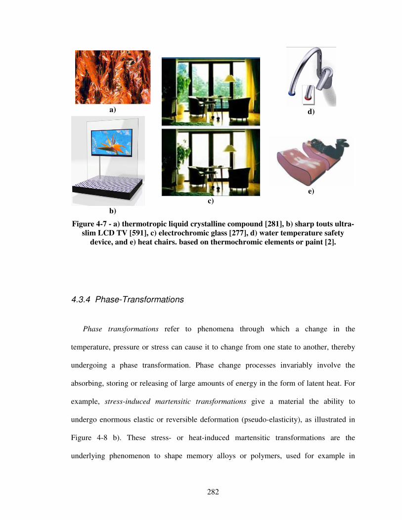
282
a)
d)
b)
c)
e)
Figure 4-7 - a) thermotropic liquid crystalline compound [281], b) sharp touts ultra-
slim LCD TV [591], c) electrochromic glass [277], d) water temperature safety
device, and e) heat chairs. based on thermochromic elements or paint [2].
4.3.4 Phase-Transformations
Phase transformations refer to phenomena through which a change in the
temperature, pressure or stress can cause it to change from one state to another, thereby
undergoing a phase transformation. Phase change processes invariably involve the
absorbing, storing or releasing of large amounts of energy in the form of latent heat. For
example, stress-induced martensitic transformations give a material the ability to
undergo enormous elastic or reversible deformation (pseudo-elasticity), as illustrated in
Figure 4-8 b). These stress- or heat-induced martensitic transformations are the
underlying phenomenon to shape memory alloys or polymers, used for example in
283
eyeglass frames that are amazingly bendable, medical stents for opening arteries that are
implanted in a compressed form and then expand to the right size and shape when
warmed by the body, tiny actuators that eject disks form laptop computers, small
microvalves and a host of other devices, all share a common material technology.
Also, since phase-changing materials can be designed to absorb or release energy at
predictable temperatures, they have naturally been explored for use in architecture as a
way of helping deal with the thermal environment in a building (e.g., phase-change
wallboards). Furthermore, patented technologies exist for embedding microencapsulated
phase-changing materials in a textile as illustrated in Figure 4-8 a) – i.e., as a person
exercises and generates heat, the materials undergo a phase change and absorb excess
heat, thus keeping the body cooler. As the body cools down, and heat is needed, the
phase-changing materials begin to release heat to warm the body.
Thus, phase changing materials are commonly used for thermal energy storage for
insulation and electronics and recently as nonvolatile memory in computer microchips
(since once a solid state phase changing material reaches a prescribed temperature, it
liquefies and absorbs heat without any additional temperature change). Also, these
materials are used to control the stress transfer between rigid elements in a matrix
material (in the flexible state, a composite material is heated and the phase changing
material changes to a liquid state, thus effectively inhibiting stress transfer between the
rigid elements in the composite). Another example is the use thermal Velcro fasteners
with clasps made from a nickel titanium shape memory alloy that closes through thermal
stimuli, as shown in Figure 4-8 c).
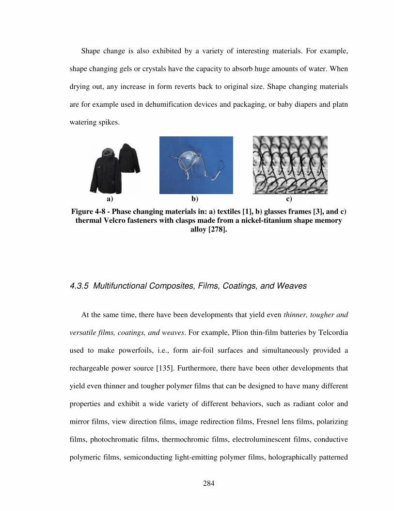
284
Shape change is also exhibited by a variety of interesting materials. For example,
shape changing gels or crystals have the capacity to absorb huge amounts of water. When
drying out, any increase in form reverts back to original size. Shape changing materials
are for example used in dehumification devices and packaging, or baby diapers and platn
watering spikes.
a) b) c)
Figure 4-8 - Phase changing materials in: a) textiles [1], b) glasses frames [3], and c)
thermal Velcro fasteners with clasps made from a nickel-titanium shape memory
alloy [278].
4.3.5 Multifunctional Composites, Films, Coatings, and Weaves
At the same time, there have been developments that yield even thinner, tougher and
versatile films, coatings, and weaves. For example, Plion thin-film batteries by Telcordia
used to make powerfoils, i.e., form air-foil surfaces and simultaneously provided a
rechargeable power source [135]. Furthermore, there have been other developments that
yield even thinner and tougher polymer films that can be designed to have many different
properties and exhibit a wide variety of different behaviors, such as radiant color and
mirror films, view direction films, image redirection films, Fresnel lens films, polarizing
films, photochromatic films, thermochromic films, electroluminescent films, conductive
polymeric films, semiconducting light-emitting polymer films, holographically patterned
285
films, piezoelectric films, as well as chemically sensitive color- and shape-changing
films. Besides films, analogous paints and coatings, optionally enhanced with
nanoparticles, exist. Also, electro-optical, dichroic, photochromic or holographically
patterned glasses as well as fiber-optic, electroluminescent, thermochromic,
photochromic and phase-changing weaves and fabrics can be designed.
Especially with respect to carbon-fiber-reinforced thermoplastic materials or hollow
structural member which contain combustible gases, new polymers, or hydrogen-
generation materials are proposed to make autophagous (self-consuming) systems that
accommodate operational stresses as well as contribute to fuel supply. [135]. Also, fiber
batteries can be used to make powerfibers, i.e., fiber batteries incorporated into
reinforcing architectures as a source of rechargeable power. Furthermore, lightweight
laminated material systems containing recesses in which a wide array of feature,
including sensors, damping material, and channels for wiring can be incorporated are
being realized. An example is the fabrication of laminated materials incorporating
cavities to achieve acoustic damping [135].
Moreover, fiber-optic cables can be embedded in different materials to serve as strain
or crack detectors in the primary material. Other damage assessment approaches in
composites are piezoelectric, magnetostrictive and electric resistance technologies. Fiber-
optic strands can however also be used for aesthetic functionality, such as building
composites or laminates by waving fiber-optic strands that are lighted by light-emitting
diodes. High-performance thermoset matrix composites having unique phase-separated
regions that respond to strains by toughening are also under investigation. The proposed
repair resin additives are activated by fracture-induced strain and act to arrest propagating
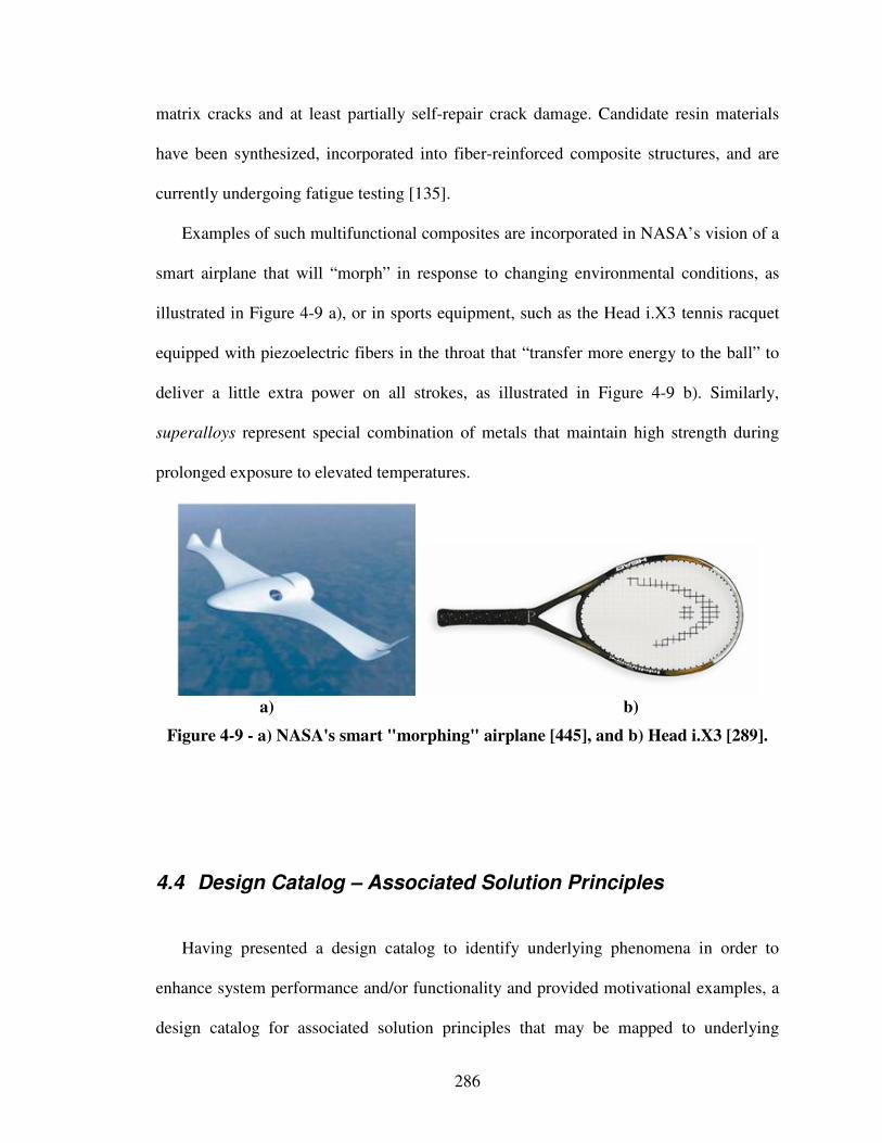
286
matrix cracks and at least partially self-repair crack damage. Candidate resin materials
have been synthesized, incorporated into fiber-reinforced composite structures, and are
currently undergoing fatigue testing [135].
Examples of such multifunctional composites are incorporated in NASA’s vision of a
smart airplane that will “morph” in response to changing environmental conditions, as
illustrated in Figure 4-9 a), or in sports equipment, such as the Head i.X3 tennis racquet
equipped with piezoelectric fibers in the throat that “transfer more energy to the ball” to
deliver a little extra power on all strokes, as illustrated in Figure 4-9 b). Similarly,
superalloys represent special combination of metals that maintain high strength during
prolonged exposure to elevated temperatures.
a) b)
Figure 4-9 - a) NASA's smart "morphing" airplane [445], and b) Head i.X3 [289].
4.4 Design Catalog – Associated Solution Principles
Having presented a design catalog to identify underlying phenomena in order to
enhance system performance and/or functionality and provided motivational examples, a
design catalog for associated solution principles that may be mapped to underlying
287
phenomena is developed in the following. The focus of the classification schemes for
integrated product and materials design developed in this work is on providing
phenomena and associated solution principles for embodying the most prominent
functional relationships of changing, storing and transforming energy. Moreover, a
design catalog with associated solution principles is provided only for the phenomenon of
(in)elastic deformation.
For effective and efficient integrated design of material and product concepts it is
crucial to identify phenomena as well as associated governing solution principles on
multiple scales in addition to system-level product specific physical effects that can be
found in the literature. Leveraging multiscale phenomena and associated solution
principles to embody multilevel functional relationships, designers are enabled to
determine product and material system concepts that narrow the gap to the desired
performance goals when specific more or less advanced materials can not be readily
selected from databases or catalogs. Classifying solution principles in terms of length
scales is based on the work of Smith [610], who states that structure is best considered by
different length scales.
From a macro-material-level perspective, examples of phenomena and associated
solution principles (provided in brackets) are:
• inertia (translational, rotational, moment of area, radius of inertia, etc.),
• friction (solid-solid, solid-liquid, solid-gas, etc.),
• (in)elastic deformation (monolithic materials, structural elements, composite
structures, etc.),
• Poisson’s ratio (monolithic materials, composite structures, etc.)
288
• connections (form, force or material fittings, boundary conditions, etc.),
• size (effect of defects in a volume, dimensions, etc.),
• constituents (composites versus monolithic materials),
• surfaces (form, topologies, coatings, etc.),
• etc.
From a meso-material-level perspective, examples of phenomena and associated
solution principles (provided in brackets) are:
• friction (granular materials, powders, asperities and actual contact surface,
topologies, etc.),
• (in)elastic deformation (honeycomb-core sandwiches, fiber composite materials,
etc.),
• Poisson’s ratio (chiral structures, fiber composites, etc.),
• size (dimensions relative to reinforcement or second phases or other
microstructure features),
• etc.
From a micro-material-level perspective, examples of phenomena and associated
solution principles (provided in brackets) are:
• (in)elastic deformation (foams, microtruss structures or laminates, particle or
dispersion composites, multi-phase or powder mixtures, machine-augmented
composites, microstructure composites, etc.),
• Poisson’s ratio (foams, microporous polymers, etc.)
• size (dimensions and distributions of phases, etc.),
• constituents (elements, molecular structure, etc.),
289
• stress or heat induced martensitic transformations as well as solid solutions, such
as those obtained by alloying,
• friction (grain or phase boundaries, topologies of phases, crystal systems (cubic,
tetragonal, orthorhombic, hexagonal, rhombohedral, monoclinic, triclinic), lattice
orientations, etc.),
• etc.
It is emphasized that certain of these latter attributes are amenable to first principles
calculations for resulting responses or properties (e.g., elastic constants, thermal
conductivity, nucleation of defects, etc.). This list is of course inexhaustive, but is
sufficient to convey that multiscale phenomena and associated solution principles at the
material level facilitate definition of system sub-functions and related modeling
principles. The identification of principal solution alternatives based on phenomena and
associated solution principles is facilitated through the use of morphological charts [773].
A systematic approach to creative discovery is thus achieved by enumerating parameters
characterizing a subject and combining the parameters in new and different ways.
As illustrated in the qualitative complexity profile for materials design given in
Figure 4-10, complexity exponentially increases when phenomena or associated solution
principles at lower scales are leveraged. For example, leveraging molecular assemblies
on picoscales gives a designer nearly unlimited concept flexibility, but, at the same time
exponentially increased complexity (amount of information). In some instances,
enhanced product performance may justify such an amount of information and resulting
complexity – in others however not. In this context, complexity profiles are attention
directing tools introduced by Bar-Yam [42]. A complexity profile counts the number of
290
independent effects at a particular scale and includes the effects that have impact at larger
scales. The use of the term complexity reflects a quantitative theory of the degree of
difficulty of describing a system’s behavior. In it’s most basic form, this theory simply
counts the number of independent effects as a measure of the complexity of a system or
amount of information available. Thus, the complexity profile characterizes system
behavior by describing the complexity as a function of scale.
A complexity profile can also be interpreted in terms of flexibility. From a design
synthesis perspective, phenomena and associated solution principles are leveraged for
concept generation. Hence, the more complexity, i.e., amount of information, at a
designer’s disposal, the higher will be a designer’s flexibility. A designer then has to
focus on the value of information available, as addressed in Chapter 5. However, from
this perspective is becomes clear that growing complexity through integrated product and
materials design suggests more responsibility for designers. Because for example
materials scientists focusing on specific phenomena or solution principles can not be
expected to anticipate all the consequences of designs at a system level when interactions
are taken into account, synthesizing phenomena and associated solution principles is a
major responsibility of system designers. System designers then need to focus on
orchestrating the interaction of complex assemblies.
In the following, a design catalog with associated solution principles is provided for
the phenomenon of (in)elastic deformation. The phenomenon of (in)elastic deformation is
selected since it is one of the most frequently encountered in materials design.
Classifying criteria of associated solution principles are specific length scales at which
solutions occur and characteristic generic terms of subsolutions. The design catalog
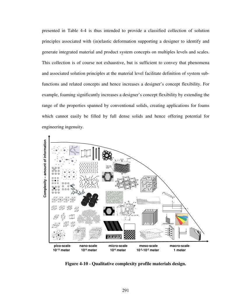
291
presented in Table 4-4 is thus intended to provide a classified collection of solution
principles associated with (in)elastic deformation supporting a designer to identify and
generate integrated material and product system concepts on multiples levels and scales.
This collection is of course not exhaustive, but is sufficient to convey that phenomena
and associated solution principles at the material level facilitate definition of system sub-
functions and related concepts and hence increases a designer’s concept flexibility. For
example, foaming significantly increases a designer’s concept flexibility by extending the
range of the properties spanned by conventional solids, creating applications for foams
which cannot easily be filled by full dense solids and hence offering potential for
engineering ingenuity.
pico-scale nano-scale micro-scale meso-scale macro-scale
10-13 meter 10-9 meter 10-6 meter 10-3-10-2 meter 1 meter
Co
mp
lexit
y –
am
ou
nt
of
info
rma
tio
n
z
1
2
3
y
y
Figure 4-10 - Qualitative complexity profile materials design.
292
In the following, a design catalog with associated solution principles is provided for
the phenomenon of (in)elastic deformation. The phenomenon of (in)elastic deformation is
selected since it is one of the most frequently encountered in materials design.
Classifying criteria of associated solution principles are specific length scales at which
solutions occur and characteristic generic terms of subsolutions. The design catalog
presented in Table 4-4 is thus intended to provide a classified collection of solution
principles associated with (in)elastic deformation supporting a designer to identify and
generate integrated material and product system concepts on multiples levels and scales.
This collection is of course not exhaustive, but is sufficient to convey that phenomena
and associated solution principles at the material level facilitate definition of system sub-
functions and related concepts and hence increases a designer’s concept flexibility. For
example, foaming significantly increases a designer’s concept flexibility by extending the
range of the properties spanned by conventional solids, creating applications for foams
which cannot easily be filled by full dense solids and hence offering potential for
engineering ingenuity.
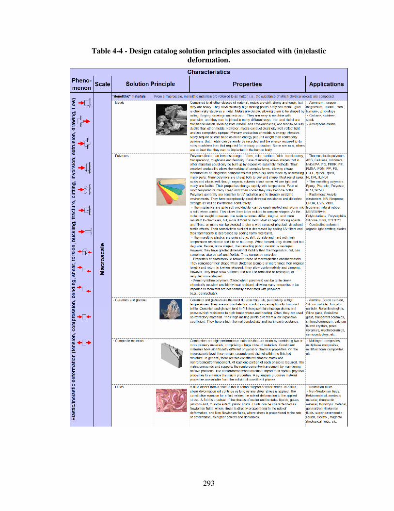
293
Table 4-4 - Design catalog solution principles associated with (in)elastic
deformation.
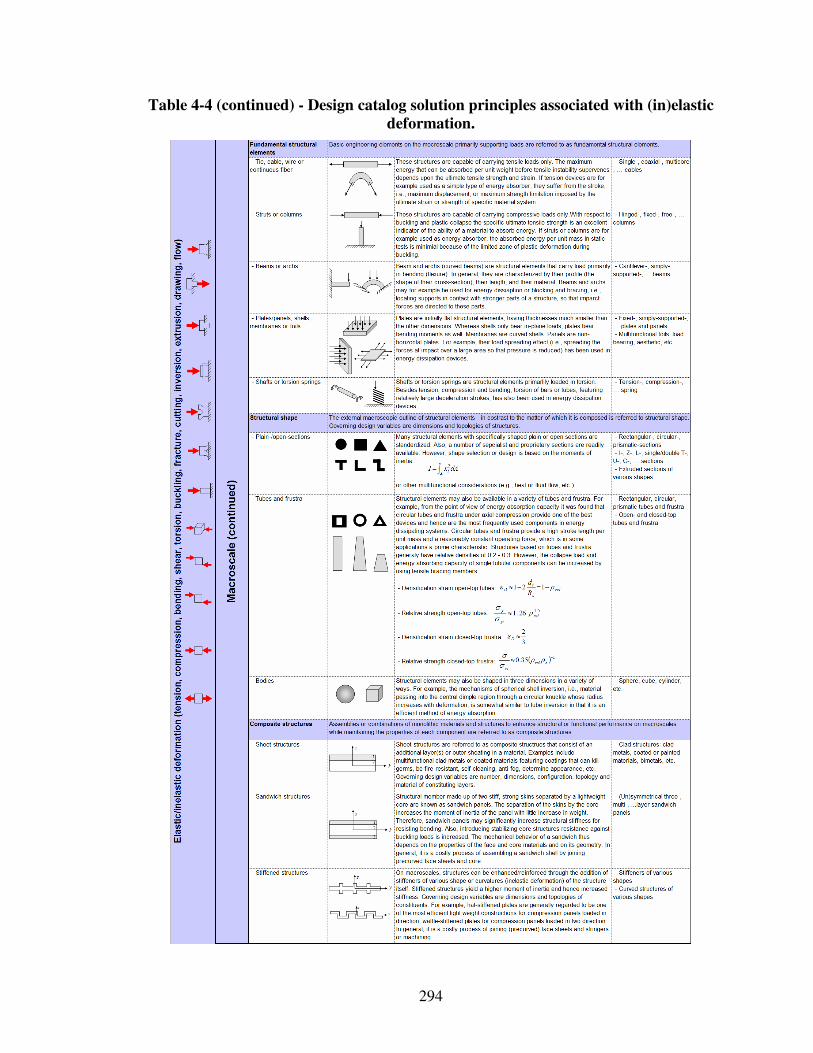
294
Table 4-4 (continued) - Design catalog solution principles associated with (in)elastic
deformation.
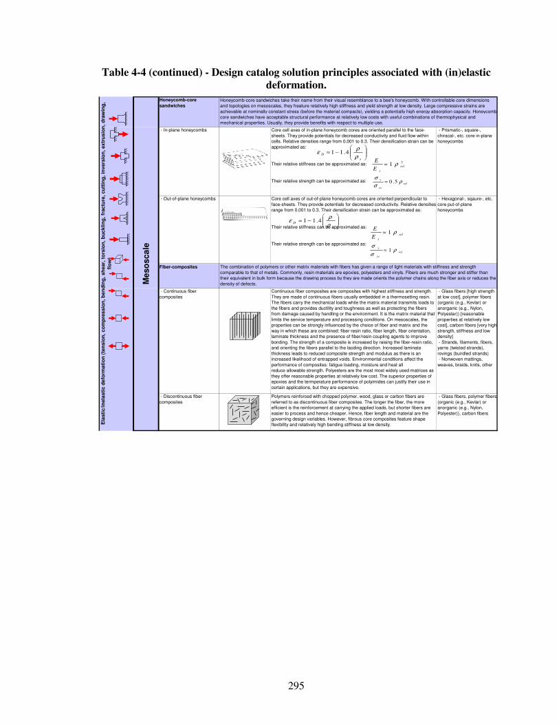
295
Table 4-4 (continued) - Design catalog solution principles associated with (in)elastic
deformation.
Honeycomb-core
sandwiches
- In-plane honeycombs Core cell axes of in-plane honeycomb cores are oriented parallel to the face-
sheets. They provide potentials for decreased conductivity and fluid flow within
cells. Relative densities range from 0.001 to 0.3. Their densification strain can be
approximated as:
Their relative stiffness can be approximated as:
Their relative strength can be approximated as:
- Prismatic-, square-,
chiracal-, etc. core in-plane
honeycombs
- Out-of-plane honeycombs Core cell axes of out-of-plane honeycomb cores are oriented perpendicular to
face-sheets. They provide potentials for decreased conductivity. Relative densities
range from 0.001 to 0.3. Their densification strain can be approximated as:
Their relative stiffness can be approximated as:
Their relative strength can be approximated as:
- Hexagonal-, sqaure-, etc.
core put-of-plane
honeycombs
Fiber-composites
- Continuous fiber
composites
Continuous fiber composites are composites with highest stiffness and strength.
They are made of continuous fibers usually embedded in a thermosetting resin.
The fibers carry the mechanical loads while the matrix material transmits loads to
the fibers and provides ductility and toughness as well as protecting the fibers
from damage caused by handling or the environment. It is the matrix material that
limits the service temperature and processing conditions. On mesoscales, the
properties can be strongly influenced by the choice of fiber and matrix and the
way in which these are combined: fiber-resin ratio, fiber length, fiber orientation,
laminate thickness and the presence of fiber/resin coupling agents to improve
bonding. The strength of a composite is increased by raising the fiber-resin ratio,
and orienting the fibers parallel to the laoding direction. Increased laminate
thickness leads to reduced composite strength and modulus as there is an
increased likelihood of entrapped voids. Environmental conditions affect the
performance of composites: fatigue loading, moisture and heat all
reduce allowable strength. Polyesters are the most most widely used matrices as
they offer reasonable properties at relatively low cost. The superior properties of
epoxies and the termperature performance of polyimides can justify their use in
certain applications, but they are expensive.
- Glass fibers [high strength
at low cost], polymer fibers
(organic (e.g., Kevlar) or
anorganic (e.g., Nylon,
Polyester)) [reasonable
properties at relatively low
cost], carbon fibers [very high
strength, stiffness and low
density]
- Strands, filaments, fibers,
yarns (twisted strands),
rovings (bundled strands)
- Nonwoven mattings,
weaves, braids, knits, other
- Discontinuous fiber
composites
Polymers reinforced with chopped polymer, wood, glass or carbon fibers are
referred to as discontinuous fiber composites. The longer the fiber, the more
efficient is the reinforcement at carrying the applied loads, but shorter fibers are
easier to process and hence cheaper. Hence, fiber length and material are the
governing design variables. However, fibrous core composites feature shape
flexibility and relatively high bending stiffness at low density.
- Glass fibers, polymer fibers
(organic (e.g., Kevlar) or
anorganic (e.g., Nylon,
Polyester)), carbon fibers
Me
so
sca
le
Ela
sti
c/i
nela
sti
c d
efo
rma
tio
n (
ten
sio
n,
co
mp
res
sio
n,
be
nd
ing
, sh
ear,
to
rsio
n,
bu
ckli
ng
, fr
ac
ture
, cu
ttin
g,
inv
ers
ion
, ex
tru
sio
n,
dra
win
g,
flo
w)
Honeycomb-core sandwiches take their name from their visual resemblance to a bee's honeycomb. With controllable core dimensions
and topologies on mesoscales, they freature relatively high stiffness and yield strength at low density. Large compressive strains are
achievable at nominally constant stress (before the material compacts), yielding a potentially high energy absorption capacity. Honeycomb-
core sandwiches have acceptable structural performance at relatively low costs with useful combinations of thermophysical and
mechanical properties. Usually, they provide benefits with respect to multiple use.
The combination of polymers or other matrix materials with fibers has given a range of light materials with stiffness and strength
comparable to that of metals. Commonly, resin materials are epoxies, polyesters and vinyls. Fibers are much stronger and stiffer than
their equivalent in bulk form because the drawing process by they are made orients the polymer chains along the fiber axis or reduces the
density of defects.
−≈
s
Dρ
ρε 4.11
31 rel
sE
Eρ≈
rel
ys
y ρσ
σ5.0≈
rel
sE
Eρ1≈
rel
ys
y ρσ
σ1≈
−≈
s
Dρ
ρε 4.11
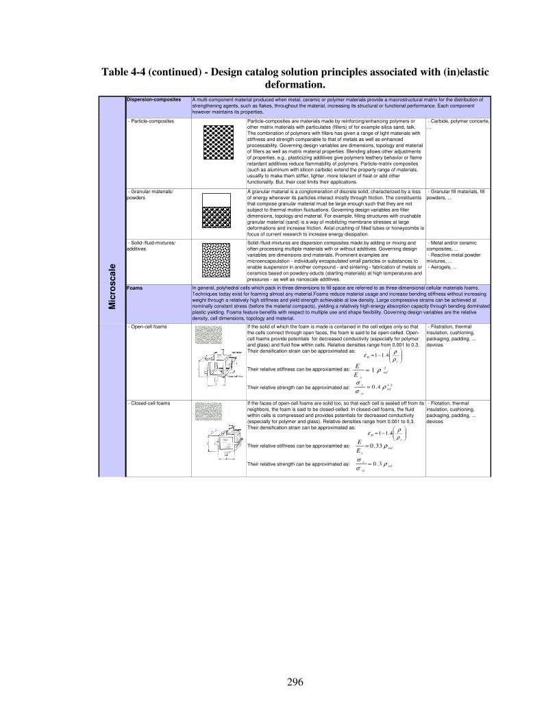
296
Table 4-4 (continued) - Design catalog solution principles associated with (in)elastic
deformation.
Dispersion-composites
- Particle-composites Particle-composites are materials made by reinforcing/enhancing polymers or
other matrix materials with particulates (fillers) of for example silica sand, talk.
The combination of polymers with fillers has given a range of light materials with
stiffness and strength comparable to that of metals as well as enhanced
processability. Governing design variables are dimensions, topology and material
of fillers as well as matrix material properties. Blending allows other adjustments
of properties, e.g., plasticizing additives give polymers leathery behavior or flame
retardant additives reduce flammability of polymers. Particle-matrix composites
(such as aluminum with silicon carbide) extend the property range of materials,
usuallly to make them stiffer, lighter, more tolerant of heat or add other
functionality. But, their cost limits their applications.
- Carbide, polymer concerte,
…
- Granular-materials/
powders
A granular material is a conglomeration of discrete solid, characterized by a loss
of energy whenever its particles interact mostly through friction. The constituents
that compose granular material must be large enough such that they are not
subject to thermal motion fluctuations. Governing design variables are filler
dimensions, topology and material. For example, filling structures with crushable
granular material (sand) is a way of mobilizing membrane stresses at large
deformations and increase friction. Axial crushing of filled tubes or honeycombs is
focus of current research to increase energy dissipation.
- Granular fill materials, fill
powders, ...
- Solid-/fluid-mixtures/
additives
Solid-/fluid-mixtures are dispersion composites made by adding or mixing and
often processing multiple materials with or without additives. Governing design
variables are dimensions and materials. Prominent examples are
microencapsulation - individually encapsulated small particles or substances to
enable suspension in another compound - and sintering - fabrication of metals or
ceramics based on powdery educts (starting materials) at high temperatures and
pressures - as well as nanoscale additives.
- Metal and/or ceramic
composites, ...
- Reactive metal powder
mixtures, ...
- Aerogels, ...
Foams
- Open-cell foams If the solid of which the foam is made is contained in the cell edges only so that
the cells connect through open faces, the foam is said to be open-celled. Open-
cell foams provide potentials for decreased conductivity (especially for polymer
and glass) and fluid flow within cells. Relative densities range from 0.001 to 0.3.
Their densification strain can be approximated as:
Their relative stiffness can be approxiamted as:
Their relative strength can be approximated as:
- Filatration, thermal
insulation, cushioning,
packaging, padding, ...
devices
- Closed-cell foams If the faces of open-cell foams are solid too, so that each cell is sealed off from its
neighbors, the foam is said to be closed-celled. In closed-cell foams, the fluid
within cells is compressed and provides potentials for decreased conductivity
(especially for polymer and glass). Relative densities range from 0.001 to 0.3.
Their densification strain can be approximated as:
Their relative stiffness can be approxiamted as:
Their relative strength can be approximated as:
- Flotation, thermal
insulation, cushioning,
packaging, padding, ...
devices
Mic
roscale
A multi-component material produced when metal, ceramic or polymer materials provide a macrostructural matrix for the distribution of
strengthening agents, such as flakes, throughout the material, increasing its structural or functional performance. Each component
however maintains its properties.
In general, polyhedral cells which pack in three dimensions to fill space are referred to as three-dimensional cellular materials foams.
Techniques today exist for foaming almost any material.Foams reduce material usage and increase bending stiffness without increasing
weight through a relatively high stiffness and yield strength achievable at low density. Large compressive strains can be achieved at
nominally constant stress (before the material compacts), yielding a relatively high energy absorption capacity through bending dominated
plastic yielding. Foams feature benefits with respect to multiple use and shape flexibility. Governing design variables are the relative
density, cell dimensions, topology and material.
−=
s
Dρ
ρε 4.11
21 rel
sE
Eρ≈
5.14.0 rel
ys
y ρσ
σ≈
rel
sE
Eρ33.0≈
rel
ys
y ρσ
σ3.0≈
−=
s
Dρ
ρε 4.11
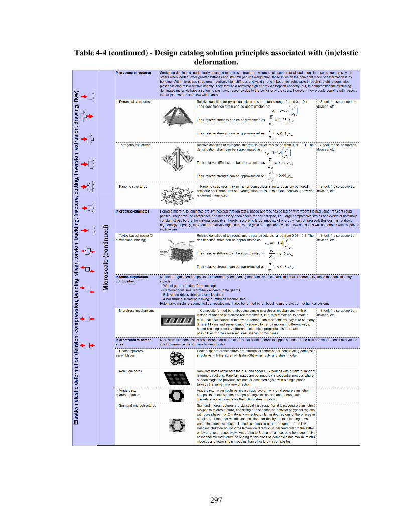
297
Table 4-4 (continued) - Design catalog solution principles associated with (in)elastic
deformation.
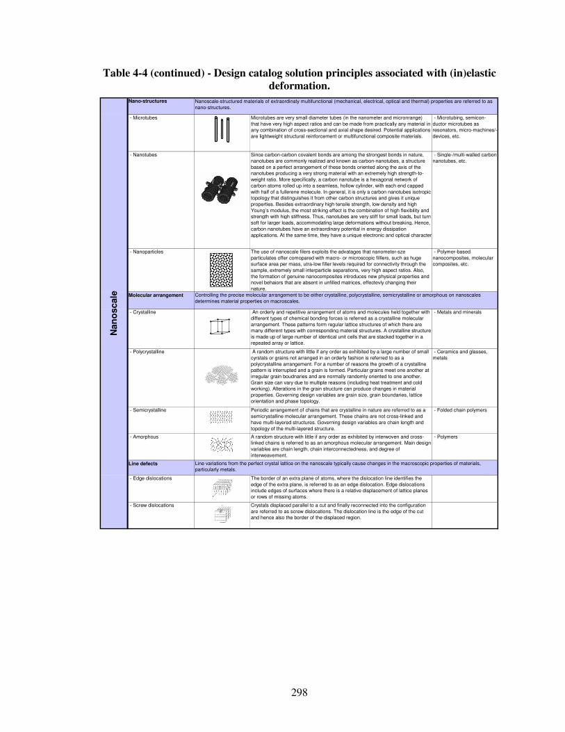
298
Table 4-4 (continued) - Design catalog solution principles associated with (in)elastic
deformation.
Nano-structures
- Microtubes Microtubes are very small diameter tubes (in the nanometer and micronrange)
that have very high aspect ratios and can be made from practically any material in
any combination of cross-sectional and axial shape desired. Potential applications
are lightweight structural reinforcement or multifunctional composite materials.
- Microtubing, semicon-
ductor microtubes as
resonators, micro-machines/-
devices, etc.
- Nanotubes Since carbon-carbon covalent bonds are among the strongest bonds in nature,
nanotubes are commonly realized and known as carbon-nanotubes, a structure
based on a perfect arrangement of these bonds oriented along the axis of the
nanotubes producing a very strong material with an extremely high strength-to-
weight ratio. More specifically, a carbon nanotube is a hexagonal network of
carbon atoms rolled up into a seamless, hollow cylinder, with each end capped
with half of a fullerene molecule. In general, it is only a carbon nanotubes isotropic
topology that distinguishes it from other carbon structures and gives it unique
properties. Besides extraordinary high tensile strength, low density and high
Young’s modulus, the most striking effect is the combination of high flexibility and
strength with high stiffness. Thus, nanotubes are very stiff for small loads, but turn
soft for larger loads, accommodating large deformations without breaking. Hence,
carbon nanotubes have an extraordinary potential in energy dissipation
applications. At the same time, they have a unique electronic and optical character.
- Single-/multi-walled carbon
nanotubes, etc.
- Nanoparticles The use of nanoscale filers exploits the advatages that nanometer-sze
particulates offer comopared with macro- or microscopic filllers, such as huge
surface area per mass, utra-low filler levels required for connectivity through the
sample, extremely small interparticle separations, very high aspect ratios. Also,
the formation of genuine nanocomposites introduces new physical properties and
novel behaiors that are absent in unfilled matrices, effectevly changing their
nature.
- Polymer-based
nanocomposites, molecular
composites, etc.
Molecular arrangement
- Crystalline An orderly and repetitive arrangement of atoms and molecules held together with
different types of chemical bonding forces is referred as a crystalline molecular
arrangement. These patterns form regular lattice structures of which there are
many different types with corresponding material structures. A crystalline structure
is made up of large number of identical unit cells that are stacked together in a
repeated array or lattice.
- Metals and minerals
- Polycrystalline A random structure with little if any order as exhibited by a large number of small
cyrstals or grains not arranged in an orderly fashion is referred to as a
polycrystalline arrangement. For a number of reasons the growth of a crystalline
pattern is interrupted and a grain is formed. Particular grains meet one another at
irregular grain boudnaries and are normally randomly oriented to one another.
Grain size can vary due to multiple reasons (including heat treatment and cold
working). Alterations in the grain structure can produce changes in material
properties. Governing design variables are grain size, grain boundaries, lattice
orientation and phase topology.
- Ceramics and glasses,
metals
- Semicrystalline Periodic arrangement of chains that are crystalline in nature are referred to as a
semicrystalline molecular arrangement. These chains are not cross-linked and
have multi-layered structures. Governing design variables are chain length and
topology of the multi-layered structure.
- Folded chain polymers
- Amorphous A random structure with little if any order as exhibited by interwoven and cross-
linked chains is referred to as an amorphous molecular arrangement. Main design
variables are chain length, chain interconnectedness, and degree of
interweavement.
- Polymers
Line defects
- Edge dislocations The border of an extra plane of atoms, where the dislocation line identifies the
edge of the extra plane, is referred to as an edge dislocation. Edge dislocations
include edges of surfaces where there is a relative displacement of lattice planes
or rows of missing atoms.
- Screw dislocations Crystals displaced parallel to a cut and finally reconnected into the configuration
are referred to as screw dislocations. The dislocation line is the edge of the cut
and hence also the border of the displaced region.
Nanoscale-structured materials of extraordinaty multifunctional (mechanical, electrical, optical and thermal) properties are referred to as
nano-structures.
Nan
oscale Controlling the precise molecular arrangement to be either crystalline, polycrystalline, semicrystalline or amorphous on nanoscales
determines material properties on macroscales.
Line variations from the perfect crystal lattice on the nanoscale typically cause changes in the macroscopic properties of materials,
particularly metals.
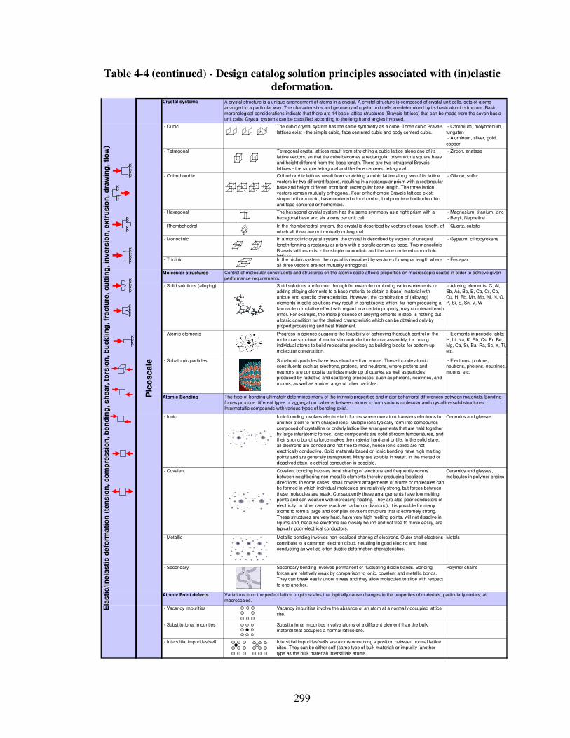
299
Table 4-4 (continued) - Design catalog solution principles associated with (in)elastic
deformation.
Crystal systems
- Cubic The cubic crystal system has the same symmetry as a cube. Three cubic Bravais
lattices exist - the simple cubic, face centered cubic and body centerd cubic.
- Chromium, molybdenum,
tungsten
- Aluminum, silver, gold,
copper
- Pyrite, garnet - Tetragonal Tetragonal crystal lattices result from stretching a cubic lattice along one of its
lattice vectors, so that the cube becomes a rectangular prism with a square base
and height different from the base length. There are two tetragonal Bravais
lattices - the simple tetragonal and the face centered tetragonal.
- Zircon, anatase
- Orthorhombic Orthorhombic lattices result from stretching a cubic lattice along two of its lattice
vectors by two different factors, resulting in a rectangular prism with a rectangular
base and height different from both rectangular base length. The three lattice
vectors remain mutually orthogonal. Four orthorhombic Bravais lattices exist:
simple orthorhombic, base-centered orthorhombic, body-centered orthorhombic,
and face-centered orthorhombic.
- Olivine, sulfur
- Hexagonal The hexagonal crystal system has the same symmetry as a right prism with a
hexagonal base and six atoms per unit cell.
- Magnesium, titanium, zinc
- Beryll, Nepheline
- Rhombohedral In the rhombohedral system, the crystal is described by vectors of equal length, of
which all three are not mutually orthogonal.
- Quartz, calcite
- Monoclinic In a monoclinic crystal system, the crystal is described by vectors of unequal
length forming a rectangular prism with a parallelogram as base. Two monoclinic
Bravais lattices exist - the simple monoclinic and the face centered monoclinic
lattices.
- Gypsum, clinopyroxene
- Triclinic In the triclinic system, the crystal is described by vectore of unequal length where
all three vectors are not mutually orthogonal.
- Feldspar
Molecular structures
- Solid solutions (alloying) Solid solutions are formed through for example combining various elements or
adding alloying elements to a base material to obtain a (base) material with
unique and specific characteristics. However, the combination of (alloying)
elements in solid solutions may result in constituents which, far from producing a
favorable cumulative effect with regard to a certain property, may counteract each
other. For example, the mere presence of alloying elments in steel is nothing but
a basic condition for the desired characteristic which can be obtained only by
propert processing and heat treatment.
- Alloying elements: C, Al,
Sb, As, Be, B, Ca, Cr, Co,
Cu, H, Pb, Mn, Mo, Ni, N, O,
P, Si, S, Sn, V, W
- Atomic elements Progress in science suggests the feasibility of achieving thorough control of the
molecular structure of matter via controlled molecular assembly, i.e., using
individual atoms to build molecules precisely as building blocks for bottom-up
molecular construction.
- Elements in periodic table:
H, Li, Na, K, Rb, Cs, Fr, Be,
Mg, Ca, Sr, Ba, Ra, Sc, Y, Ti,
etc.
- Subatomic particles Subatomic particles have less structure than atoms. These include atomic
constituents such as electrons, protons, and neutrons, where protons and
neutrons are composite particles made up of quarks, as well as particles
produced by radiative and scattering processes, such as photons, neutrinos, and
muons, as well as a wide range of other particles.
- Electrons, protons,
neutrons, photons, neutrinos,
muons, etc.
Atomic Bonding
- Ionic Ionic bonding involves electrostatic forces where one atom transfers electrons to
another atom to form charged ions. Multiple ions typically form into compounds
composed of crystalline or orderly lattice-like arrangements that are held together
by large interatomic forces. Ionic compounds are solid at room temperatures, and
their strong bonding force makes the material hard and brittle. In the solid state,
all electrons are bonded and not free to move, hence ionic solids are not
electrically conductive. Solid materials based on ionic bonding have high melting
points and are generally transparent. Many are soluble in water. In the melted or
dissolved state, electrical conduction is possible.
Ceramics and glasses
- Covalent Covalent bonding involves local sharing of electrons and frequently occurs
between neighboring non-metallic elements thereby producing localized
directions. In some cases, small covalent arragements of atoms or molecules can
be formed in which individual molecules are relatively strong, but forces between
these molecules are weak. Consequently these arrangements have low melting
points and can weaken with increasing heating. They are also poor conductors of
electricity. In other cases (such as carbon or diamond), it is possible for many
atoms to form a large and complex covalent structure that is extremely strong.
These structures are very hard, have very high melting points, will not dissolve in
liquids and, because electrons are closely bound and not free to move easily, are
typically poor electrical conductors.
Ceramics and glasses,
molecules in polymer chains
- Metallic Metallic bonding involves non-localized sharing of electrons. Outer shell electrons
contribute to a common electron cloud, resulting in good electric and heat
conducting as well as often ductile deformation characteristics.
Metals
- Secondary Secondary bonding involves permanent or fluctuating dipole bands. Bonding
forces are relatively weak by comparison to ionic, covalent and metallic bonds.
They can break easily under stress and they allow molecules to slide with respect
to one another.
Polymer chains
Atomic Point defects
- Vacancy impurities Vacancy impurities involve the absence of an atom at a normally occupied lattice
site.
- Substitutional impurities Substitutional impurities involve atoms of a different element than the bulk
material that occupies a normal lattice site.
- Interstitial impurities/self Interstitial impurities/selfs are atoms occupying a position between normal lattice
sites. They can be either self (same type of bulk material) or impurity (another
type as the bulk material) interstitials atoms.
Ela
sti
c/i
ne
las
tic
de
form
ati
on
(te
ns
ion
, c
om
pre
ss
ion
, b
en
din
g,
sh
ea
r, t
ors
ion
, b
uc
kli
ng
, fr
ac
ture
, c
utt
ing
, in
ve
rsio
n,
ex
tru
sio
n,
dra
win
g,
flo
w)
Pic
osc
ale
Control of molecular constituents and structures on the atomic scale affects properties on macroscopic scales in order to achieve given
performance requirements.
The type of bonding ultimately determines many of the intrinsic properties and major behavioral differences between materials. Bonding
forces produce different types of aggregation patterns between atoms to form various molecular and crystalline solid structures.
Intermetallic compounds with various types of bonding exist.
Variations from the perfect lattice on picoscales that typically cause changes in the properties of materials, particularly metals, at
macroscales.
A crystal structure is a unique arrangement of atoms in a crystal. A crystal structure is composed of crystal unit cells, sets of atoms
arranged in a particular way. The characteristics and geometry of crystal unit cells are determined by its basic atomic structure. Basic
morphological considerations indicate that there are 14 basic lattice structures (Bravais lattices) that can be made from the seven basic
unit cells. Crystal systems can be classified according to the length and angles involved.
Face centeredSimple cubic Body centered
y
300
4.5 Discussion, Limitations and Opportunities for Future Work – Design Catalogs
The fundamental assumption underlying the development of design catalogs is that
design catalogs facilitate function-based systematic design, support a rationally bounded
designer, extend cognitive abilities, and hence increase a designer’s concept flexibility, as
it has been shown in the literature [551]. However, even though design catalogs provide
an extensive classified collection of known and proven solutions for easy retrieval or
stimulation, any classification scheme must be considered as a living document which is
to be continuously updated, extended and maintained to keep up with the ever evolving
body of knowledge.
As noted by Roth [552], this was originally the case for the periodic table of elements
used in chemistry as well. The periodic table for the chemical elements is a prototype for
all design catalogs. The “white boxes” that could not be filled there led to the postulation
and subsequent discovery of new elements. Hence, design catalogs can still have unkown
solutions that belong in the “white boxes”. However, even a more or less complete
classification scheme greatly facilitates the generation of concepts, even those that were
typically not considered before, and therefore significantly increases the designer’s
concept flexibility. Also, it strengthens a designer’s confidence when selecting the most
promising solution principles that nothing essential has been overlooked.
Key aspects of the developed design catalogs are the multidisciplinary exchange of
knowledge, the exploration of the relationships between phenomena and associated
solution principles at multiple scales and their differing behaviors, the understanding that
material properties are dictated at the smallest scale, and thus recognition that the
301
overarching macro-scale behavior can be controlled by underlying pico/nano-scale
design. Operating at the phenomenal level underlines multidisciplinary problem solving
from a systems perspective. Hence, designers are encouraged to first think about the crux
of the underlying problem and not limit themselves to problem definition to possible
actions within a specific domain, thinking that needs of specific concepts are prima facie
rather than articulating a more fundamental problem and finding a different concept that
would call into question these specific needs. Having decided on the specific
phenomenon and associated solution principle, material properties become the starting
point of design activities, rather than being chosen or selected after the conceptual design
phase is completed.
The crux of design catalogs in general is to provide knowledge in a form classified
for easy retrieval, overlayed with applications. In essence, the design catalogs developed
in this work represent an open-ended map that enable a designer to identify underlying
phenomena and associated solution principles rather than a prescriptive set of directions
simply to instruct in the implementation of new materials and technologies is required.
Focusing on phenomena and associated solution principles, i.e., property-structure
relations classified in terms of length scales, but not a specific case or material artifact, a
designer is able to step out of the technological cycle of obsolescence and evolution.
As argued by Eberhart and Clougherty [175], no matter how fast the computer, if it
must search for an optimum property using accurate analysis models of an infinite
number of materials, it will still require infinite time to perform the search. Hence, the
viewpoint of materials design as an automated search exercise is very limited. Also,
scientific, mostly complex multiscale models might not be necessary in many cases
302
because the goal of materials is not to accurately predict material properties but to satisfy
performance requirements. Also, bottom-up analysis is not design. The key to materials
design is leveraging structure-property relations on multiple length scales to facility the
design of material concepts.
As a result, this approach requires a much more active engagement by the designer
than do the typical selection approaches. However, if knowledge of a material/system is
tied only into an account of its properties/specifications and a description of its current
application, then that knowledge may become obsolete along with the material/system
quickly. By operating at the level of phenomena and associated solution principles, a
particular material/system at any given time is only illustrative of the possibilities, not
their determinant. As materials/systems cycle through evolution and obsolescence, the
questions that are raised by their uses as for example smart materials should remain.
For example, smart materials may inherently act as sensors or actuators. In their role
as sensors, a smart material responds to changes in its environment by generating a
perceivable response. For example, a thermochromic material could be used directly as a
device for sensing a change in the temperature of an environment via its color response
capabilities. Smart materials such as piezoelectric crystals could also be used as actuators
by passing an electric current through the material to create a force. Hence, phenomena
and associated solution principles represent the “least common denominator” from which
concepts, applications or specific cases can be derived and are thus better suited as root
mechanisms at a designer’s disposal than for example an exhaustive collection of cases
even in times of powerful computational capabilities.
303
Having developed a design catalog providing phenomena for embodying the most
prominent functional relationships of changing, storing and transforming energy and a
design catalog with associated solution principles embodying the phenomenon (in)elastic
deformation, design catalogs for more functional relationships and associated solution
principles are to be generated. Design catalogs providing solution principles to other
phenomena than (in)elastic deformation are not that exhaustive as the one presented in
Table 4-4. However, generation of design catalogs may require extensive allocation of
resources. But, to fully leverage the potential embedded in materials design, to achieve
system performance goals for the first time, or to realize “smart” materials and
“artificially intelligent systems”, and thereby design and develop products satisfying
dynamic performance requirements, it is advisable to generate design catalogs containing
solution principles for all other phenomena besides (in)elastic deformation.
In order to turn the design catalogs developed in this work into “living” documents
and thereby overcome of the limitations listed above in the future, a web-based Function-
based Materials Design (FMD) tool has been developed. Through the web-based FMD
tool, i) the function-based systematic approach to conceptual materials design is
described, and ii) an open environment to edit existing and add new design catalogs for
solution-principles associated with certain phenomena is provided. The web-based FMD
tool is developed to provide a tradeoff between a “living” (easy to change, edit and
extend) and “moderating” (easy to control and manage changes and extensions) effect
when editing existing and developing new design catalogs.
Future work might involve either total integration of the web-based FMD tool with
large-scale established open environments such as Wikipedia or advanced database and

304
search algorithm programming using for example open-source SQL databases and
Apache web servers. However, future work in this area only involves bringing the
instantiated web-based FMD tool in a different form, depending on the targeted user, but,
keeping it’s basic structure. The design catalogs developed in this dissertation are based
on a systematic representation which is well suited storing information content in a
computer-based form.
Translating design catalogs in advanced computer-based form is a future research
endeavor. There are currently many workable computer-enhanced systems that have been
developed to aid a designer in coping, understanding, and effectively utilizing complex
information sets. Some of the first explorations in this area were called knowledge-based
or expert systems. Expert systems essentially codify best practices into a set of rules that
can be used to search through data and then advise a designer on the historically best
responses to a specific situation. The knowledge is contained in the rules, and the
intelligence belongs to the operator.
Fuzzy logic adds a dimensionality to expert systems. Whereas expert systems match
current conditions to past conditions that have a known best response, fuzzy logic
additionally maps current data to multiple sets of data to produce more than one
possibility. This approach is an attempt to shift some of the intelligence from the operator
to the system so as to bring in some of the instinctive reasoning that allows new and
possibly even better responses than in the past.
Both expert systems and fuzzy logic are considered supervised in that a human still
makes the final decision. However, some extend into more advanced modes that contain
algorithms that mimic human decision-making. Nevertheless, these systems do not

305
control activities, they simply provide the guidance. They aid a designer in understanding
and utilizing a complex information environment.
A related but more sophisticated approach is when the involved technological actions
actually anticipate human needs or interests and are already working by the time the
human action actually begins. In order anticipate needs it is clearly necessary to
understand or comprehend a complex situation. Hence, this approach belongs to the
hugely complex field of artificial intelligence, with its own nuances of what is meant by
the term. In its most general form however, it can be understood as the characteristic of a
cognitively based advanced use environment. It refers to programs that can perform
activities that are typically associated with human intelligence, such as recognition. One
definition of artificial intelligence is the study of knowledge representation and
interference mechanisms necessary for reasoning and problem solving [631]. A detailed
review is given by Russell and Norvig [555]. However, artificial intelligence solution
approaches, most often in the form of heuristic search, can be carried out in a more
complex and less well structured problem space than for example optimization-based
requiring idealizations of real-world problems.
Artificial intelligence is a generic term that has been used to refer to any information-
based system that has a decision-making component, regardless of whether that
component is advisory, as in expert systems, or is part of an unsupervised neural network
that is capable of extrapolating into the unknown. However, the term is more frequently
used in relation to artificial neural networks, modeled after the human brain’s neural
networks and designed to be capable of learning. These networks contain vast amounts of
data that are sorted and put through an exhaustive trial and error pattern recognition
306
testing that is known as training. Once trained, it has the experience to make a judgment
call when out-of-bounds data are encountered or unprecedented situations arise. Each
level in the development of artificial intelligence has progressively reduced the human
participation in the real-time activity of decision-making. However, more demands are
placed in the still emerging and evolving field of providing reasoning capabilities, i.e.,
the ability to make inferences that in turn govern responses.
4.6 On Verification and Validation – Theoretical Structural Validation
In this chapter, theoretical structural validation as one aspect of the validation square
is addressed. An overview of the validation performed in this dissertation is presented in
Section 1.3. Specific details related to validating the construct presented in this Chapter
are illustrated in Figure 3-10.
Theoretical structural validation refers to accepting the validity of individual
constructs used in the systematic approach and accepting the internal consistency of the
way the constructs are put together. Theoretical structural validation is carried out in this
chapter using a systematic procedure consisting of a) identifying the method’s scope of
application, b) reviewing the relevant literature and identifying the strengths and
limitations of the constructs in the literature, and c) identifying the gaps in existing
literature, and d) determining which constructs are leveraged in the systematic approach
while exploring the advantages, disadvantages, and accepted domain of application. The
307
internal consistency of the individual constructs is checked by a critical review of the
literature.
Concerning the phenomena and associated solution principles design catalogs, it has
been argued why design catalogs are appropriate to facilitate function-based systematic
integrated product and materials design from a systems perspective. Also, it has been
argued that design catalogs are foundational to developing automated tools to facilitate
function-based systematic design, such as for example case-based reasoning tools. Based
on the existing literature, it is shown that design catalogs have been previously used and
validated for facilitating function-based systematic design in different domains
successfully. However, design catalogs for the materials domain as developed in this
work have not yet been addressed. However, in order to develop wide ranged principal
solution alternatives and increase a designer’s concept flexibility, it is crucial to
determine phenomena and associated solution principles on multiple system levels
including the multiscale materials level.
From the critical review of the literature, it is identified that design catalogs have
been widely used in conceptual design, but, focus has so far been on developing design
catalogs for various types of connections, guides and bearings, power generation and
transmission, kinematics and mechanisms, gearboxes, safety technology, ergonomics, as
well as production processes. Also, physical effects for the specific domains of
mechanical and electrical engineering as well as a few chemical effects have been
classified in the context of systems design. However, so far focus has been on phenomena
and associated solution principles have only been addressed for the product domain from
a macro-level perspective, not considering the potential embedded in materials on
308
multiple scales. During conceptual design, designers are currently used to manipulating
materials at the macro-scale only after having determined a system concept.
In this work, previous efforts are extended to include phenomena and associated
solution principles of relevance to integrated product and materials design. By focusing
on phenomena and associated solution principles – structure-property relations that drive
larger-scale behavior on smaller scales – but not an infinite number of cases or material
artifacts, conceptual product and materials design is integrated and materials design itself
rendered more systematic and domain-independent. In order to facilitate function-based
integrated design of product and material concepts from a systems perspective at the level
of phenomena and associated solution principles, the development of supporting
classification schemes and design catalogs to support a designer in designing material and
product concepts in an integrated fashion.
Due to the logical procedure of literature review, gap analysis, as well as
development and evaluation of new design catalogs, the theoretical structural validity of
the construct is accepted. Examples to support accepting theoretical structural validity
with respect to design catalogs for phenomena are presented in Section 4.3. A thorough
literature review to support accepting theoretical structural validity with respect to design
catalogs for associated solution principles is presented in the Appendix. Accepting
internal consistency of the way constructs are put together is investigated in Chapter 6.
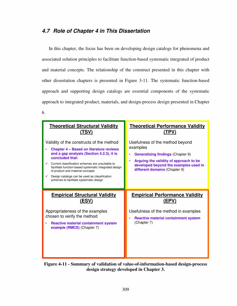
309
4.7 Role of Chapter 4 in This Dissertation
In this chapter, the focus has been on developing design catalogs for phenomena and
associated solution principles to facilitate function-based systematic integrated of product
and material concepts. The relationship of the construct presented in this chapter with
other dissertation chapters is presented in Figure 3-11. The systematic function-based
approach and supporting design catalogs are essential components of the systematic
approach to integrated product, materials, and design-process design presented in Chapter
6.
Empirical Structural Validity (ESV)
Appropriateness of the exampleschosen to verify the method
• Reactive material containment system example (RMCS) (Chapter 7)
Theoretical Performance Validity (TPV)
Usefulness of the method beyond
examples
• Generalizing findings (Chapter 9)
• Arguing the validity of approach to be developed beyond the examples used in different domains (Chapter 9)
Theoretical Structural Validity (TSV)
Validity of the constructs of the method
• Chapter 4 – Based on literature reviews and a gap analysis (Section 4.2.3), it is concluded that:
� Current classification schemes are unsuitable to
facilitate function-based systematic integrated design
of product and material concepts
� Design catalogs can be used as classification
schemes to facilitate systematic design
Empirical Performance Validity (EPV)
Usefulness of the method in examples
• Reactive material containment system (Chapter 7)
Figure 4-11 - Summary of validation of value-of-information-based design-process
design strategy developed in Chapter 3.
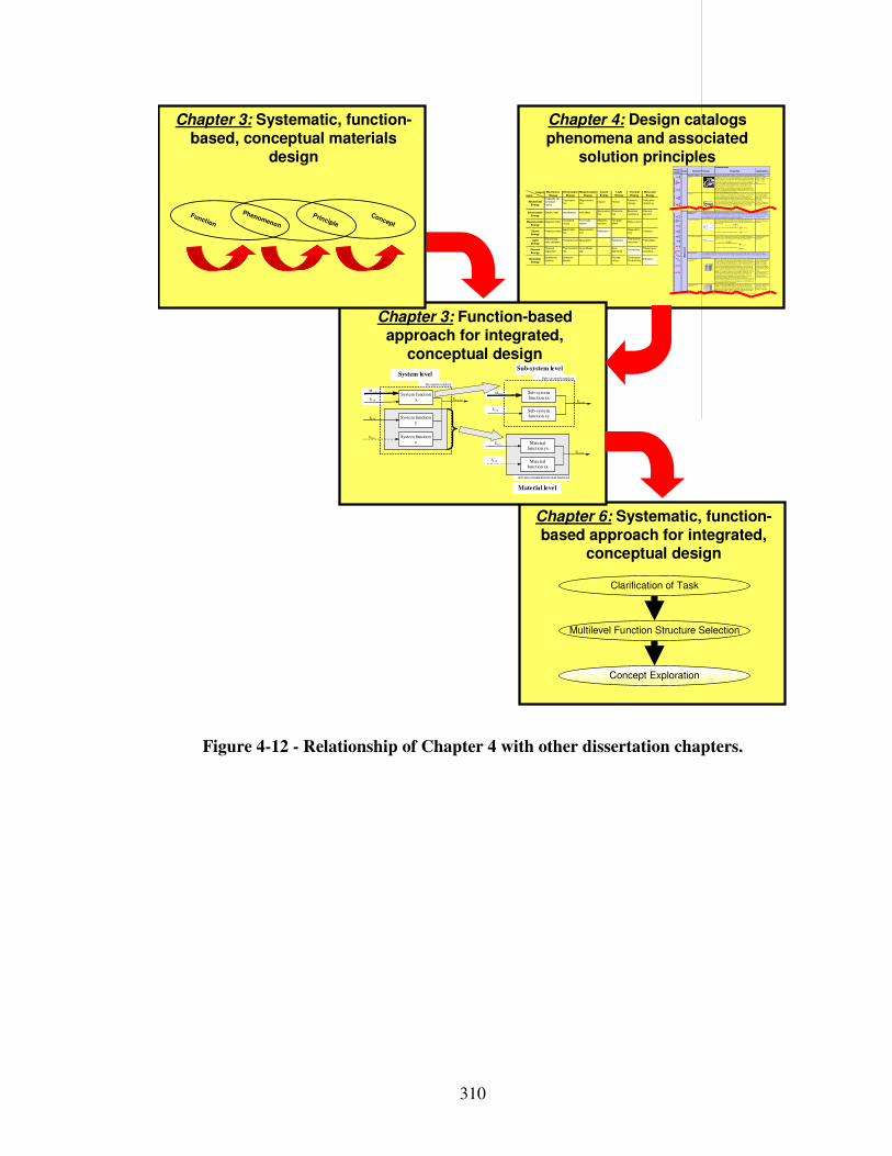
310
Chapter 6: Systematic, function-based approach for integrated,
conceptual design
Multilevel Function Structure Selection
Clarification of Task
Concept Exploration
Chapter 4: Design catalogs phenomena and associated
solution principles
Chapter 3: Function-based approach for integrated,
conceptual design
Pheno-menon
Scale Properties Applications
"Monolithic" materials
- Metals Compared to all other classes of material, metals ar e stiff, strong and tough, but
they are heavy. They have relatively high melting points. Only one metal - gold - is
chemically s table as a metal. Metals are ductile, allowing them to be shaped by
roll ing, forging, drawingn and extrusion. They are easy to machine with precision,
and they can be joined in many di fferent ways . Iron and nickel are trans itional
metals involving both metall ic and covalent bonds, and tend to be less ductile than
other metals. However, metals conduc t elec tricity well , reflec t light and are completely opaque. Primary pr oduction of metals is energy intensive. Many
require at least twice as much energy per unit weight than commodity polymers.
But, metals can general ly be recycled and the energy required to do so is much
less than that requried for primary production. Some are tox ic, others ar e so inert
that they can be implanted in the human body.
- A luminum-, copper- ,
magnesium-, nickel-, steel-,
titanium-, z inc -al loys
- Car bon-, stainles-, …
steels
- Amor phous metals, …
Ela
stic
/in
ela
sti
c d
efo
rma
tio
n (
ten
sio
n,
co
mpre
ssio
n, b
en
din
g,
sh
ea
r, t
ors
ion
, bu
cklin
g, fr
actu
re,
cu
ttin
g, in
vers
ion
, e
xtr
usio
n,
Characteristics
Solution Principle
- Polymers
From a macroscale, monoli thic materials are r efer red to as matter, i .e., the substance of which physical objects ar e composed.
Polymers feature an immense range of form, color, surface finish, translucency,
transparency, toughness and flexibil ity. Ease of molding allows shapes that in
other materials could only be bui lt up by expensive assembly methods. Their
excellent workabi lity al lows the molding of complex forms , allowing cheap manufacture of integrated components that previously were made by assembling
many par ts. Many polymers are cheap both to buy and shape. Most res ist water,
acids and alkalis wel l, though organic solvents attack some. A ll are light and many
are flexible. Their properties change rapidly with temperature. Even at room
temperature many cr eep and when cooled they may become brittle. Polymers
generally are sens itive to UV radiation and to strongly oxidizing env ironments.
- Thermosplastic polymers :
ABS, Cellulose, Ionomers ,
Nylon/PA, PC, PEEK, PE,
PMMA, POM, PP, PS, PTFE, tpPVC, tpPU,
PET/PETE/PBT
- Thermosetting polymers:
Epoxy, Phenolic , Polyester,
tsPU, tsPVC
- E las tomers: Acrylic
machining.
Honeycomb-core
sandwiches
- In-plane honeycombs Cor e cel l axes of in-plane honeycomb cores are oriented paral lel to the face-sheets. They provide potentials for decreased conductivity and fluid flow within
cells. Relative densities range from 0.001 to 0.3. Their densification s train can be
approx imated as:
Their relative s ti ffness can be approximated as:
Their relative s tr ength can be approximated as:
- P rismatic- , square-, chiracal- , etc . core in-plane
honeycombs
- Out-of- plane honeycombs Cor e cel l axes of out-of-plane honeycomb cores ar e oriented perpendicular to face-sheets. They provide potentials for decr eased conductivity. Relative dens ities
range from 0.001 to 0.3. Their densification strain can be approximated as:
Their relative s ti ffness can be approximated as:
Their relative s tr ength can be approximated as:
- Hexagonal- , sqaure-, etc. cor e put-of-plane
honeycombs
Fiber-composites
- Continuous fiber
composites
Continuous fiber composites are composites with highes t stiffness and s trength.
They ar e made of continuous fibers usually embedded in a thermosetting r esin.
The fibers carry the mechanical loads while the matrix mater ial transmits loads to
the fibers and provides ductili ty and toughness as well as protecting the fibers from damage caused by handling or the environment. It is the matrix mater ial that
l imits the service temperature and processing conditions. On mesoscales, the
proper ties can be strongly influenced by the choice of fiber and matrix and the
way in which these are combined: fiber -res in ratio, fiber length, fiber orientation,
laminate thickness and the presence of fiber/resin coupling agents to improve
bonding. The strength of a composite is inc reased by raising the fiber-resin ratio,
and orienting the fibers parallel to the laoding direction. Increased laminate
thickness leads to reduced composite s trength and modulus as there is an
incr eased l ikelihood of entrapped voids. Environmental conditions affect the
performance of composites: fatigue loading, moisture and heat al l
reduce allowable strength. Polyesters are the most most widely used matrices as they offer reasonable properties at relatively low cost. The superior properties of
epoxies and the termperature per formance of polyimides can justify their use in
certain appl ications, but they are expensive.
- Glass fiber s [high strength
at low cost], polymer fibers
(or ganic (e.g., Kevlar) or
anorganic (e.g., Nylon, Polyester)) [reasonable
properties at relatively low
cos t], carbon fibers [very high
strength, stiffness and low
density]
- S trands, fi laments, fibers,
yarns (twis ted strands),
rov ings (bundled strands)
- Nonwoven mattings ,
weaves, braids , knits, other
- Discontinuous fiber
composites
Polymers reinforced with chopped polymer, wood, glass or carbon fibers are
referr ed to as discontinuous fiber composites. The longer the fiber, the more
efficient is the reinfor cement at carrying the applied loads , but shorter fibers are
eas ier to process and hence cheaper. Hence, fiber length and mater ial are the governing design variables. However, fibr ous core composites feature shape
flexibil ity and relatively high bending stiffness at low dens ity.
- Glass fiber s, polymer fibers
(or ganic (e.g., Kevlar) or
anorganic (e.g., Nylon,
Polyester)), carbon fibers
Me
so
scale
Ela
sti
c/i
ne
las
tic
de
form
ati
on
(te
ns
ion
, c
om
pre
ss
ion
, b
en
din
g,
sh
ea
r, t
ors
ion
, b
uc
kli
ng
, fr
actu
re,
cu
ttin
g,
inve
rsio
n,
ex
tru
sio
n,
dra
win
g,
flo
w)
Honeycomb-core sandwiches take their name from their visual resemblance to a bee's honeycomb. With control lable core dimensions
and topologies on mesoscales, they freature relatively high s ti ffness and yield strength at low density. Large compressive strains are
achievable at nominally cons tant stress ( before the material compacts), yielding a potentially high energy absorption capacity. Honeycomb-core sandwiches have acceptable str uctur al performance at relatively low costs with useful combinations of thermophysical and
mechanical properties. Usual ly, they provide benefits with respect to multiple use.
The combination of polymers or other matrix materials with fibers has given a range of light materials with sti ffness and s tr ength
compar able to that of metals. Commonly, resin materials ar e epoxies , polyesters and vinyls. Fibers are much stronger and stiffer than
their equivalent in bulk form because the drawing process by they are made orients the polymer chains along the fiber axis or reduces the density of defects.
−≈
s
D ρ
ρε 4.11
31 rel
sE
Eρ≈
rel
ys
yρ
σ
σ5.0≈
relsE
Eρ1≈
rel
ys
yρ
σ
σ1≈
−≈
s
Dρ
ρε 4.11
Output
Input
Mechanical
Energy
(In)elastic de-
formationInertia
…
Electrostric-tion
…
Magnetostric-tion
…
Impact…
Friction…
Pressure change
…
Dislocation hardening
…
Electrostatic
Energy
Electric field
…
Interference
…
Hall-effect
…
Electrostric-tion
…
Photostric-tion
…
Electrical resistance
…
Galvanic element
…
Magnetostatic
Energy
Magnetic field
…
Oscillating circuit
…
Ferromag-netism
…
Magneto-striction
…
Farraday-effect
…
Eddy current
…
Sound
Energy
Pressure wave
…
Electrostric-tion
…
Magnetostric-tion
…
Reflection
…
Noise dam-ping
…
Elasticity
…
Light
Energy
Electromag-netic radiation
…
Photostric-tion
…
Absorption
…
Refraction
…
Thermolumi-nescence
…
Photoeffect
…
Thermal
Energy
Thermal expansion
…
Thermoelectricity
…
Curie-Weiss law
…
Pyro-electricity
…
Convection
…
Phase trans-formation
…
Molecular
Energy
Exothermic reaction
…
Molecular dipoloe
…
Fluores-cence
…
CombustionConductivity
…
Adhesion
…
Light
Energy
Thermal
Energy
Molecular
Energy
Mechanical
Energy
Electrostatic
Energy
Magnetostatic
Energy
Sound
Energy
Chapter 3: Systematic, function-based, conceptual materials
design
Advanced mult ifunctional material
Ex,in
Mx,in
Ex,in
System boundary
System function x Exyz,out
System function z
System function y
Ey,in
Sz,in
Mx,in Sub-system function xx
Ex,out
Sub-system function xy
Sz,in
Ey,in Material function yx
Eyz,out
Material function zx
Sub-system boundary System level
Sub-system level
Material level
Concept
Principle
Phenomenon
Function
Figure 4-12 - Relationship of Chapter 4 with other dissertation chapters.
311
Chapter 5 Systematic Value-Of-Information-Based Strategy To Design-Process Generation and Selection
In this chapter, the requirements for the systematic approach – “increasing a
designer’s design-process flexibility”, “systematically generating and selecting design-
process alternatives”, and “evaluating the performance of different design-process
alternatives” – are addressed. All requirements for the systematic approach are listed in
Table 1-6. The constructs of the systematic approach developed to address the
requirements are highlighted in Figure 5-1. A portion of Table 1-6 that is relevant to this
chapter is reproduced in Table 5-1. The constructs of the systematic approach developed
in this chapter are i) a systematic strategy to design-process design from a decision-
centric perspective, and ii) a value-of-information-based Process Performance Indicator
for assessing the performance of design-process alternatives. The reactive material
containment system example and optoelectronic communication system example are used
in Chapters 7 and 8 respectively for validation of these constructs of the systematic
approach. The strategy to design-process generation and selection as well as the value-of-
information based Process Performance Indicator are used for answering the second
research question posed in this dissertation. Their relationship with the second research
question and the supporting hypotheses is presented in Figure 5-1. An overview of the
systematic approach to design-process design to increase a designer’s design-process
flexibility is presented in Figure 5-2.
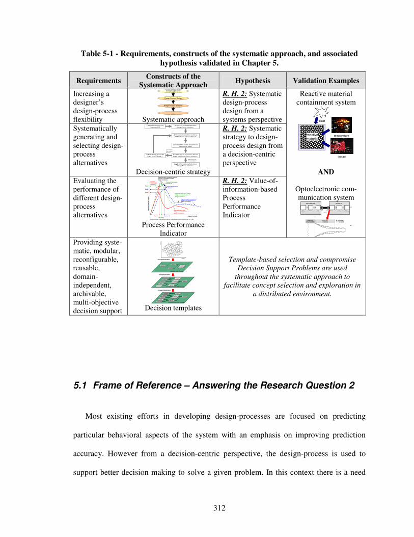
312
Table 5-1 - Requirements, constructs of the systematic approach, and associated
hypothesis validated in Chapter 5.
Requirements Constructs of the
Systematic Approach Hypothesis Validation Examples
Increasing a designer’s design-process flexibility
Design-Process Design
…
Design-Process Selection
Concept Exploration
Systematic approach
R. H. 2: Systematic design-process design from a systems perspective
Systematically generating and selecting design-process alternatives
2) Select and Evaluate Simple Initial
Design-Process Alternative.
4) Evaluate Most Truthful Design-Process
Alternative Available.
Step 7: Select Satisficing Embodiment Design-Process Alternative.
1) Formulate Decision Using
Compromise DSP.
3) Determine Decision Point by Solving
cDSP for Maximum Expected Payoff.
High Process Per-
formance Indicator
Low Process
Performance
Indicator
5) Evaluate Process Performance Indicator
Simple Initial Design-Process Alternative .
6) Refine Design-Process and
Repeat Steps 3 Through 5.
Decision-centric strategy
R. H. 2: Systematic strategy to design-process design from a decision-centric perspective
Evaluating the performance of different design-process alternatives Design Variable
Exp
ec
ted
Ove
rall P
ayo
ff
Expected payoff usingdesign process alternative 1(global information)
Expected payoff using refined design process alternative 2(global information)
Payoff 2
Decision 1 Decision 2
Payoff 1
Process Performance Indicator 1
Expected payoff using most accurate physical or simulation models(local information)
Process Performance Indicator 2
Decisions based on predicted behavior using design process alternatives 1, 2, 3, etc.
Process Performance Indicator 3
Expected payoff using refined design process alternative 3(global information)
Payoff 3
Decision 3 Process Performance
Indicator
R. H. 2: Value-of-information-based Process Performance Indicator
Reactive material containment system
temperature
impact
reactive
material
blast
AND
Optoelectronic com-munication system
Providing syste-matic, modular, reconfigurable, reusable, domain-independent, archivable, multi-objective decision support
Concept Generation
Concept Selection
Concept Exploration
Alternatives Rank
Instantiated sDSP Template
Importance
Attributes
Goals
Preferences
Variables
Parameters
Constraints
Response
Objective
Analysis
Driver
Fully Instantiated cDSP Template
Goals
Preferences
Variables
Parameters
Constraints
Response
Objective
Analysis
Driver
Partially Instantiated cDSP Template
Att
rib
ute
2
Attribute 1
Concept 2
Concept 5
Concept 1 Concept 3
Concept 6
Concept 4
Decision templates
Template-based selection and compromise
Decision Support Problems are used
throughout the systematic approach to
facilitate concept selection and exploration in
a distributed environment.
5.1 Frame of Reference – Answering the Research Question 2
Most existing efforts in developing design-processes are focused on predicting
particular behavioral aspects of the system with an emphasis on improving prediction
accuracy. However from a decision-centric perspective, the design-process is used to
support better decision-making to solve a given problem. In this context there is a need
Signal
(information
input)
Modulator Source
(carrier)
Detector Signal-
processor
Signal
(information
output)
Input- Output-
coupling
TRANSMITTER RECEIVER
a)
b)
NORMAL
WAVEGUIDE
OPTICAL
COUPLER
SLOW-LIGHT
WAVEGUIDE
313
for a systematic strategy to generate and select design-processes. Such a strategy should
support a designer in answering questions such as a) how appropriate is a design-process,
and b) what is the potential for refining a design-process. In this context, an appropriate
design-process is one that allows a design decision to be made concerning system
functions identified during conceptual design without excess and unneeded accuracy.
Since engineering analysis is expensive and time consuming, designers should select the
least complex but still valid design-process that provides sufficient accuracy and
resolution. Accordingly, in response to Research Question 2 –
“How can a design-process be generated and selected systematically, and additional
modeling potential and design-process alternatives be evaluated, to increase a
designer’s design-process flexibility and facilitate integrated design of product and
material concepts?”
– a value-of-information-based design-process design strategy is developed in this
chapter, as illustrated in Figure 5-2 and proposed in the second research hypothesis,
consisting of:
• “a systematic strategy to design-process generation and selection from a decision-
centric perspective, and”
• “a value-of-information-based design-process performance indicator”.
It is emphasized that the value-of-information-based design-process design strategy is
based on a decision-centric perspective of design. Also, for designing the design-process,
it is important to be able to model them in a manner that support their analysis and
reconfiguration, in other words to provide systematic, modular, reconfigurable, reusable,
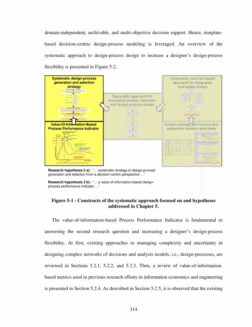
314
domain-independent, archivable, and multi-objective decision support. Hence, template-
based decision-centric design-process modeling is leveraged. An overview of the
systematic approach to design-process design to increase a designer’s design-process
flexibility is presented in Figure 5-2.
Research hypothesis 2 b): “… a value-of-information-based design-process performance indicator …”
Research hypothesis 2 a): “… systematic strategy to design-process generation and selection from a decision-centric perspective …”
Systematic design-process generation and selection
strategy
Value-Of-Information-Based Process Performance Indicator
Systematic approach for integrated product, materials,
and design-process design
Design catalogs phenomena and associated solution principles
Systematic, function-based approach for integrated,
conceptual design
Systematic mapping of classified phenomena and
solution principles from multiple scales and
disciplines to multilevel function structures
Creating multilevel function structures based on
functional analysis, abstraction and synthesis
Ex,in
M x,in
Ex,in
System boundary
System function x Exyz,out
System function z
System function y
Ey,in
Sz,i n
M x,in Sub-system function xx
Ex,out
Sub-system function xy
Sz,in
Ey,in Material function yx
Eyz,out
Material function zx
Sub-system boundarySystem level
Sub-system level
Material level
Clarification of Task
Multilevel Function Structure Selection
Concept Selection
Concept
Principle
Phenomenon
Function
Pheno-menon
Scale Properties Applications
"Monolithic" materials
- Metals Compared to a ll other classes of material , metals are stif f, strong and tough, but
they are heavy. They have rel atively hi gh melti ng points. Only one metal - gold - is
chemically stable as a metal . Metals are d uctile, all owing them to be shaped by
roll ing, forgin g, drawi ngn and extrusion. They are easy to machine with precision, and they can be j oined i n many different ways. Iron an d nickel are transit ional
metals involving both metallic and covalent bonds, and tend to be less d uctile than
other meta ls. However, metals conduct electricity well , ref lect light a nd are
completely opaque. Pri mary producti on of metals is ene rgy i ntensive. Man y
require at least twice as much energy per un it weight than commodity polymers.
But, metals can general ly be recycl ed and the energy required to do so is much l ess than that requried for primary production. Some are toxi c, others are so inert
that they can be i mpl anted in the human body.
- Al uminum-, copper-,
magnesi um-, nickel-, steel -,
ti tanium-, zinc-al loys
- Carbon-, stainles-, … steels
- Amorphous meta ls, …
Ela
sti
c/in
ela
sti
c d
efo
rmat
ion
(te
ns
ion
, c
om
pre
ssi
on
, be
nd
ing
, sh
ear
, to
rsio
n,
bu
ckl
ing
, fr
actu
re, c
utt
ing
, in
ver
sio
n, e
xtr
usi
on
,
Characteristics
Solution Principle
- Pol ymers
From a macroscale, monolith ic materials are referred to as matter, i.e., the substance of which physi cal objects are composed.
Polymers feature an immense range of form, color, surface fini sh, transluce ncy, transparency, toughness a nd f lexibility. Ease of moldi ng all ows sh apes that i n
other mate ri als could only be bui lt up by expensive assembly methods. Their
excellent workabili ty all ows the mol ding of complex forms, al lowing cheap
manufacture of i ntegrated components that previously were made b y assembling
many parts. Many polymers are cheap both to b uy and shape. Most resist water,
acids and alkali s well, though organic so lvents attack some. All are light and ma ny are fl exibl e. Their properties change rapidly with temperature. Even at room
temperature many creep and when cooled the y may become brit tl e. Pol ymers
generall y are sensiti ve to UV radiation and to strongly oxidi zing environments.
- Thermosplastic p olymers: ABS, Cellulose, Ionomers,
Nyl on/PA, PC, PEEK, PE,
PMMA, POM, PP, PS, PTFE,
tpPVC, tpPU,
PET/PETE/PBT
- Thermosett ing pol ymers: Epoxy, Phenolic, Pol yester,
tsPU, tsPVC
- El astomers: Acrylic
machining.
Honeycomb-cor e
sandwiches
- In-plane honeycombs Core cel l axes of in-plane honeycomb cores are oriented paral lel to the face-
sheets. They provide potenti als for decreased conductivity and f luid f low within
cells. Relative densit ies range from 0.001 to 0.3. Their densif icatio n strain can be
approximated as:
Their relat ive st iffness can be approximated as:
Their relat ive stren gth can be ap proximated as:
- Prismati c-, square-,
chiracal-, etc. core in-plane
honeycombs
- Out-o f-plane honeycombs Core cel l axes of out-of-pl ane honeycomb cores are oriented perpendicular to
face-sheets. They provide potentials for decreased conducti vi ty. Relative densities
range from 0.001 to 0.3. Their densif ication strain can be approxi mated as:
Their relat ive st iffness can be approximated as:
Their relat ive stren gth can be ap proximated as:
- Hexagonal-, sqau re-, etc.
core put-of-plane
honeycombs
Fiber-composite s
- Conti nuous fi ber
composites
Continuous f iber composites are composi tes wi th highest st if fness and strength.
They are made of continuous fibers usuall y embedd ed in a thermosetting resin.
The f ibers carry the mechani cal loads whi le the matrix material transmits loads to the f ibers and provides ducti lity an d toughness as well as protecting the fibers
from damage caused by h andling or the environmen t. I t is the matrix material that
l imi ts the service temperature and proce ssing conditio ns. On mesoscales, the
propert ies can be strongly i nfluenced by the choice of f iber and matrix and the
way i n which these are combined: f iber-resin ratio, fi ber length, fi ber orientation,
l aminate thickness and the presence of fiber/resi n coupling agents to improve bondi ng. The strength of a composite is increased by raising the f iber-resin ratio,
and orienting the f ibers parall el to the l aoding di rection. Increased lami nate
thickness leads to reduced composite strength and modulus as there is an
i ncreased likelihood of entrapped voids. Environmental conditi ons affect the
performance of composites: fat igue l oading, moisture and heat all
reduce allowable strength. Polyesters are the most most wi dely used matri ces as they offer reasonable propertie s at relati vely low cost. The superior propert ies of
epoxies and the termperature performance of polyi mide s can justify their use in
certa in appli cations, but they are expensive.
- Glass f ibers [high strength
at low cost], polymer f ibers
(organic (e.g., Kevl ar) or anorganic (e.g., Nylon,
Polyester)) [reasonable
properties at relatively l ow
cost], carbon fibe rs [very high
strength, st if fness and low
density] - Strands, fil aments, fibers,
yarns (twisted strands),
rovi ngs (bundled strands)
- Nonwoven matt ings,
weaves, braids, knits, other
- Disco ntinuous fiber
composites
Polymers rei nforced with chopped polymer, wood, glass o r carb on f ibers are
referre d to as di scontinuous f iber composites. The longer the fi ber, the more
eff ici ent is the reinforcement at carryi ng the appli ed loads, but shorter fi bers are easier to process an d hence cheaper. Hence, f iber length and material are the
governing design variables. However, fibrous core composites fea ture shape
f lexibili ty and relati vely high bendi ng sti ffness at low densi ty.
- Glass f ibers, polymer fibers
(organic (e.g., Kevl ar) or
anorganic (e.g., Nylon, Polyester)), carbon f ibers
Me
so
sca
le
Ela
sti
c/i
ne
lasti
c d
efo
rm
ati
on
(te
ns
ion
, c
om
pre
ssio
n,
ben
din
g, sh
ear,
to
rsio
n,
buc
kli
ng
, fra
ctu
re,
cu
ttin
g,
inve
rsio
n, ex
tru
sio
n, d
raw
ing,
flo
w)
Honeycomb-core sandwiches take thei r name from their visu al resemblance to a bee's honeycomb. W ith controlla ble core di mensions
and topologies on mesoscale s, they freature relatively high stif fness and yield strength at low d ensi ty. Larg e compressive strai ns are
achievable at nominal ly constant stress (before the material compa cts), yieldi ng a potentially hi gh energy absorpti on capacity. Honeycomb-
core sandwiches have acceptabl e structural performance a t rel atively low costs with useful combinations of thermophysical and mechani cal properti es. Usually, they provide benefits with respect to mult iple use.
The combin ation of polymers or other ma trix materi als with f ibers has gi ven a range of light materi als with st iffness and strength
comparable to that of metals. Commonly, resin materi als are e poxi es, pol yesters and vinyls. Fibers are much stronger and stif fer than
thei r equivalent in bulk form because the drawing process by they are made orients the polymer ch ains along the fi ber axis or re duces the
density of defects.
−≈
s
Dρ
ρε 4.11
31rel
sE
Eρ≈
relys
y ρσ
σ5.0≈
rel
sE
Eρ1≈
r el
ys
y ρσ
σ1≈
−≈
s
D ρ
ρε 4.11
OutputInput
MechanicalEnergy
(In)elastic de-formationInertia…
Electrostric-tion…
Magnetostric-tion…
Impact…
Friction…
Pressure change…
Dislocation hardening…
Electrostatic
EnergyElectric field…
Interference…
Hall-effect…
Electrostric-tion…
Photostric-tion…
Electrical resistance…
Galvanic element…
MagnetostaticEnergy
Magnetic field…
Oscillating circuit…
Ferromag-netism…
Magneto-striction…
Farraday-effect…
Eddy current…
SoundEnergy
Pressure wave…
Electrostric-tion…
Magnetostric-tion…
Reflection …
Noise dam-ping…
Elasticity…
Light
Energy
Electromag-netic radiation…
Photostric-tion…
Absorption…
Refraction…
Thermolumi-nescence…
Photoeffect…
ThermalEnergy
Thermal expansion…
Thermoelectricity…
Curie-Weiss law…
Pyro-electricity…
Convection…
Phase trans-formation…
Molecular
Energy
Exothermic reaction…
Molecular dipoloe…
Fluores-cence…
CombustionConductivity…
Adhesion…
Light
Energy
Thermal
Energy
Molecular
Energy
Mechanical
Energy
Electrostatic
Energy
Magnetostatic
Energy
Sound
Energy
Design Variable
Ex
pec
ted
Ov
era
ll P
ayo
ff
Expected payoff usingdesign process alternative 1(global information)
Expected payoff using refined design process alternative 2(global information)
Payoff 2
Decision 1 Decision 2
Payoff 1
Process Performance Indicator 1
Expected payoff using most accurate physical or simulation models(local information)
Process Performance Indicator 2
Decisions based on predicted behavior using design process alternatives 1, 2, 3, etc.
Process Performance Indicator 3
Expected payoff using refined design process alternative 3(global information)
Payoff 3
Decision 3
Template-based decision-centric concept exploration accounting for uncertainty and
complexity of multilevel and multiscale design
Evaluation of design-process alternatives and value of additional multiscale modeling based on
Process Performance Indicator
Multilevel Function Structure Selection
Clarification of Task
Design-Process Design
Embodiment Design
Design-Process Selection
Concept Selection
Creating multilevel function structures based on
functional analysis, abstraction and synthesis
Systematic mapping of classified phenomena and solution principles from multiple scales and
disciplines to multilevel function structures
Systematic generation of multiscale design-process alternatives based on a value-of-
information-based strategy
Evaluation of design-process alternatives and additional modeling potential through a value-of-information-based Process Performance Indicator
Systematic generation of design-process alternatives based on
principles from information economics
Design-Process Evaluation
Design-Process Selection
Concept Exploration and Selection
Template-based decision-centric embodiment design
2) Select and Evaluate Simple Initial
Design Process Alternative.
4) Evaluate most truthful design process alternative available.
Step 7: Select satisficing embodiment
design process alt ernative.
1) Formulate Decision Using
Compromise DSP.
3) Determine Decision Point by Solving cDSP for Maximum Payoff.
High Process Per-
formance Indicator
Low Process Performance
Indicator
5) Evaluate Process Perf ormance Indi cator
Simple Initial Design-Process Alternative .
6) Refine Design-Process and
Repeat Steps 3 Through 5.
…
Figure 5-1 - Constructs of the systematic approach focused on and hypotheses
addressed in Chapter 5.
The value-of-information-based Process Performance Indicator is fundamental to
answering the second research question and increasing a designer’s design-process
flexibility. At first, existing approaches to managing complexity and uncertainty in
designing complex networks of decisions and analysis models, i.e., design-processes, are
reviewed in Sections 5.2.1, 5.2.2, and 5.2.3. Then, a review of value-of-information-
based metrics used in previous research efforts in information economics and engineering
is presented in Section 5.2.4. As described in Section 5.2.5, it is observed that the existing
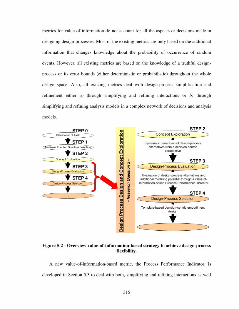
315
metrics for value of information do not account for all the aspects or decisions made in
designing design-processes. Most of the existing metrics are only based on the additional
information that changes knowledge about the probability of occurrence of random
events. However, all existing metrics are based on the knowledge of a truthful design-
process or its error bounds (either deterministic or probabilistic) throughout the whole
design space. Also, all existing metrics deal with design-process simplification and
refinement either a) through simplifying and refining interactions or b) through
simplifying and refining analysis models in a complex network of decisions and analysis
models.
Template-based decision-centric embodiment
design
Evaluation of design-process alternatives and
additional modeling potential through a value-of-
information-based Process Performance Indicator
Design-Process Evaluation
…
Design-Process Selection
Concept Exploration
De
sig
n P
roces
s D
esig
n a
nd
Co
ncep
t E
xp
lora
tio
n
-R
esea
rch
Qu
es
tio
n 2
-
Systematic generation of design-process
alternatives from a decision-centric perspective
Multilevel Function Structure Selection
Clarification of Task
Design-Process Evaluation
…
Design-Process Selection
Concept Exploration
STEP 3
STEP 0
STEP 1
STEP 2
STEP 4
STEP 2
STEP 3
STEP 4
Figure 5-2 - Overview value-of-information-based strategy to achieve design-process
flexibility.
A new value-of-information-based metric, the Process Performance Indicator, is
developed in Section 5.3 to deal with both, simplifying and refining interactions as well
316
as analysis models while not being dependent on the knowledge of a truthful design-
process or its error bounds (either deterministic or probabilistic) globally, i.e., throughout
the whole design space – crucial for many scenarios in integrated product and materials
design. Hence, the Process Performance Indicator is evaluated only with respect to local
information – information at specific points in the design space that can be readily
obtained through for example experimental testing or detailed analysis models evaluated
at specific points in the design space especially in the context of integrated product and
materials design. The Process Performance Indicator is developed to address a major
challenge identified in the May 2006 Report of the National Science Foundation Blue
Ribbon Panel on Simulation-Based Engineering Science (SBES), namely: “resolving
open problems associated with multiscale and multi-physics modeling, real-time
integration of simulation methods with measurement systems, model validation and
verification, …”.
Based on the Process Performance Indicator, developed in Section 5.3, a generally
applicable design-process generation and selection strategy is developed in Section 5.4.
This strategy combines inductive (top-down) engineering with deductive (bottom-up)
science. Advantages and limitations of the Process Performance Indicator and the design-
process generation and selection strategy are discussed in Section 5.5, along with
verification and validation in Section 5.6. However, first, in Section 5.2, a literature
review specific to value of information for decision making and a research gap analysis
are conducted.
317
5.2 Value of Information for Decision Making – A Literature Review
Complex engineered systems are inherently complex. Moreover, leveraging
phenomena and associated solution principles occurring at multiple levels and scales
through integrated product and materials design is advantageous to achieve enhanced
concept flexibility and increased overall system performance, but, disadvantageous in the
sense that a designer has to face:
• strong couplings and interactions not only between subsystems and multiple
disciplines, but also physical phenomena at various scales that must be explicitly
modeled and accounted for in decision making,
• fundamentally different (multiscale and multiphysics) types of more or less
developed analysis models (possibly describing the same physical phenomena) on
and within various scales that may fundamentally change upon refinement,
• integration of simulation methods with measurement systems, model validation
and verification,
• uncertainty generation and propagation not only between subsystems but also
between and within various scales that must be addressed, and
• significantly greater complexity of design-processes than in conventional systems,
displayed in an unmanageably large number of interactions and couplings denoted
by the number of independent design variables, inhibiting extensive and agile
design space exploration through holistic design processes consisting of rigidly
integrated simulation models.
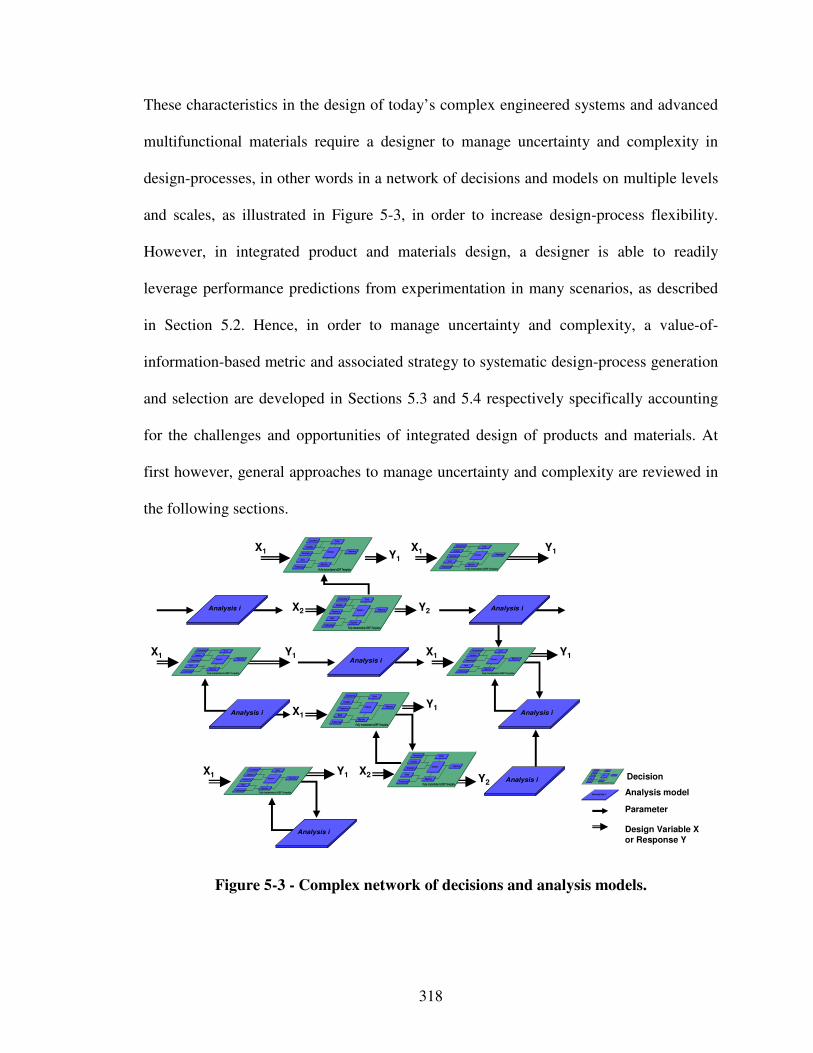
318
These characteristics in the design of today’s complex engineered systems and advanced
multifunctional materials require a designer to manage uncertainty and complexity in
design-processes, in other words in a network of decisions and models on multiple levels
and scales, as illustrated in Figure 5-3, in order to increase design-process flexibility.
However, in integrated product and materials design, a designer is able to readily
leverage performance predictions from experimentation in many scenarios, as described
in Section 5.2. Hence, in order to manage uncertainty and complexity, a value-of-
information-based metric and associated strategy to systematic design-process generation
and selection are developed in Sections 5.3 and 5.4 respectively specifically accounting
for the challenges and opportunities of integrated design of products and materials. At
first however, general approaches to manage uncertainty and complexity are reviewed in
the following sections.
X1 Y1
X2 Y2
X1
Y1
X2 Y2
Analysis i
Goals
Preferences
Variables
Parameters
Constraints
Response
Objective
Fully Instantiated cDSP Template
Driver
Analysis
Goals
Preferences
Variables
Parameters
Constraints
Response
Objective
Fully Instantiated cDSP Template
Driver
Analysis
Analysis i
Goals
Preferences
Variables
Parameters
Constraints
Response
Objective
Fully Instantiated cDSP Template
Driver
Analysis
Analysis i
X1 Y1
X1 Y1 X1 Y1
Goals
Preferences
Variables
Parameters
Constraints
Response
Objective
Fully Instantiated cDSP Template
Driver
Analysis
Goals
Preferences
Variables
Parameters
Constraints
Response
Objective
Fully Instantiated cDSP Template
Driver
Analysis
Goals
Preferences
Variables
Parameters
Constraints
Response
Objective
Fully Instantiated cDSP Template
Driver
Analysis
Goals
Preferences
Variables
Parameters
Constraints
Response
Objective
Fully Instantiated cDSP Template
Driver
Analysis
Goals
Preferences
Variables
Parameters
Constraints
Response
Objective
Fully Instantiated cDSP Template
Driver
Analysis
Analysis i
X1 Y1
Analysis i
Analysis i
Analysis i
Decision
Analysis model
Parameter
Design Variable X or Response Y
Analysis i
Goals
Preferences
Variables
Parameters
Constraints
R esponse
Objective
Fully Instantiated cDSP Template
D ri ver
Anal ysis
Figure 5-3 - Complex network of decisions and analysis models.
319
5.2.1 Systematic Approaches to Managing Uncertainty
Dealing with complex design-processes, in other words complex networks of
decisions and analysis models, a designer has to face various sources of uncertainty, such
as the one identified by Isukapalli et al. [299]:
• natural uncertainty, which is due to the inherent randomness of the physical
system. It can be further classified as parameterizable and unparameterizable
uncertainty;
• model parameter uncertainty, which is due to the incomplete knowledge of model
parameters/inputs due to insufficient or inaccurate data. Model parameter
uncertainty is reducible by sufficient data;
• model structure uncertainty, which refers to uncertain model formulation due to
approximations and simplifications in a model. It is reducible by improving model
formulation; and
• propagated uncertainty, which is uncertainty amplified in a network of decisions
and models.
Uncertainty can be epistemic (i.e., reducible uncertainty or imprecision due to ignorance
of information) or aleatory (i.e., irreducible uncertainty or variability) in nature.
However, for managing uncertainty in design, two primary approaches have been
identified: i) reducing the uncertainty itself, and ii) designing a system to be less sensitive
to uncertainty without necessarily reducing or eliminating it. However, reducing
uncertainty is feasible when a designer has large amounts of data or even better complete
knowledge. The common underlying hypothesis is that it is possible to obtain true (or
approximately true) data. This hypothesis, however, is not valid in many integrated
320
product and materials design problems due to aleatory uncertainty. Therefore, the
approach of designing a system to be less sensitive to uncertainty without eliminating or
reducing its sources in the system – called robust design (or parameter design) – is
crucial to achieve satisficing solutions.
In order to manage uncertainty, many approaches have been proposed in the literature
as reviewed in detail in Section 2.4.5 on robust design. Increasingly, probabilistic
approaches for uncertainty propagation estimating system response’s probability
distribution from the probability distribution of inputs’ variance have been studied.
Traditional approaches, such as Monte Carlo Simulation and Latin Hypercube Sampling
Techniques, are accurate but computationally expensive. On the other hand, First and
Second Order Reliability Methods (FORM/SORM) do not require intensive computing
power, but their accuracy is questionable. Recently, uncertainty propagation methods
using stochastic variables in mathematical series forms, such as Polynomial Chaos
Expansions [324] and the Stochastic Response Surface Method [298], have been used to
estimate relatively accurate probabilistic distribution of a system response with reduced
computational power.
These techniques, with the exception of computationally expensive propagation
techniques, are based on the assumption that analysis models are deterministic.
Inexpensive uncertainty propagation in non-deterministic analysis models originating
from non-parametric and un-configured noise factors or model parameter/structural
uncertainties arising from limited data or knowledge has not been addressed. Also,
stochastic programming [297] and the Minmax Deviation Approaches [54, 748] have a
limited ability to find robust solutions under model parameter uncertainty. Therefore,
321
Choi and coauthors [132] have proposed Type III robust design to manage (a) inherent
variability that is difficult or impossible to parameterize, (b) limited data, and (c) limited
knowledge, as reviewed in detail in Section 2.4.5.
Concerning propagated uncertainty, probabilistic and robust design techniques are
being infused increasingly into multidisciplinary design optimization (MDO) approaches,
as reviewed in Section 2.3.4, for formulating and concurrently solving decomposed or
partitioned complex system design problems. A few authors have focused on considering
probabilistic as well as deterministic variables and parameters in an MDO context (eg.,
[173, 241]). Other authors have focused on replacing complex, computationally-
intensive analysis routines with approximate models (e.g., [235, 329, 408]). While
approximate analysis models ease the computational burdens of MDO, they can be
inaccurate or inefficient if the responses are highly nonlinear or governed by a large
number of parameters. Therefore, Choi and coauthors [130] have presented an Inductive
Design Exploration Method (IDEM) to facilitate hierarchical materials and product
design synthesis, as reviewed in detail in Section 2.4.5.
Designing today’s complex engineered systems, a system designer almost always
faces a complex design-process, in other words a complex network of decisions and
models on multiple levels and scales. Trying to manage complexity by simplification,
additional uncertainty is introduced. Hence, managing uncertainty as described above is a
necessity. However, methods to manage uncertainty such as the ones proposed by Choi
and coauthors [130] are focus of current research activities and hence not further
considered in this work. When facing networks of decisions and models, the focus in this
322
work is not on managing uncertainty as discussed above, but, on managing complexity as
discussed in the following section.
5.2.2 Systematic Approach to Managing Complexity
Increasing the level of refinement of individual analysis models or increasing the
degree of interaction between coupled decisions or analysis models in design-processes
results in a corresponding increase in complexity (and generally accuracy) and decrease
in computational efficiency. In this work, complexity thus refers to being composed of
interconnected or interwoven parts, involved or intricate (as in structure) [715].
Complexity of a system is thus a function of a) the number of entities in the system, b)
the number and strength of interactions between the entities [40, 87], and c) the
complexity of individual entities.
Similarly, the complexity of a design-process, in other words a network of decisions
and models, is directly dependent on the strength of information flow between entities
and the complexity of individual entities. The increasing complexity of systems being
designed results in a corresponding increase in the complexity of their design-processes
[645]. In simulation-based design from a decision-centric perspective, the two key
entities of design-processes are: a) decisions, and b) analysis models that generate
information for these decisions [78, 203, 204, 434]. Hence, the complexity in design-
processes on multiple levels and scales is a result of interactions between these two
entities in a network of design decisions and the complexity of the individual entities.
323
Increasing complexity is usually associated with an increase in accuracy. But,
increased complexity is neither a necessary nor sufficient condition for accuracy.
However, in this work accuracy is defined based on its Latin roots, i.e., accurare – to take
care of. Hence, here we refer to accuracy as an exact or careful conformity to truth [715].
Also, a basic assumption of this work is that leveraging phenomena and associated
solution principles occurring at multiple levels and scales leads to increased complexity,
but also increased accuracy by “taking care of” greater detail and hence achieving a more
exact or careful conformity to truth. This increase in complexity and associated accuracy
however comes at the cost of additional modeling efforts and decreased computationally
efficiency, which in this work refers to the speed with which information for decision
making is generated and provided to decision makers. For example, while complex
design-processes that consider all interactions lead to better designs; less complex design-
processes, where some interactions are ignored are faster and more resource efficient.
Due to the tradeoff between resource efficiency and complexity, designers face the
following question – “How should the complex network of decisions and analysis models
be configured to obtain a satisficing design-process alternative without affecting the
resulting system performance?”.
In this context, ways for identifying a satisficing design-process alternative that is as
complex (accurate) as necessary and as computationally efficient as possible are to:
• refine or simplify interactions (couplings) between coupled decisions and analysis
models or complexity of individual analysis models of an existing complex
design-process alternative, or
324
• evaluate and select design-process alternatives starting from the least complex but
still valid configuration.
Consider for example a structural designer who has a design-process consisting of
decisions and analysis models for predicting the system behavior. The designer is
interested in making a decisions. The designer has an option of refining or simplifying
the design-process. The least complex but still valid initial design-process consists thus of
a network of statics models for various system components. The degree of coupling
between statics models for various system components may increased or decreased. Also,
complexity of static models can be decreased or increased by for example including
dynamic behavior or creep and therefore adding information. Both actions may thus be
taken to refine or simplify the existing design-process, thereby generating design-process
alternatives.
Refining or simplifying an existing complex design-process alternative in different
ways or selecting more or less complex design-process alternatives strategically, i.e.,
from least complex to more complex, results in different design outcomes characterized
by overall system performance. In some cases the benefits of decreased modeling efforts
and increased computational efficiency exceed the drawback of reduced system
performance, whereas in other cases, the reduction in performance is unjustifiable. If the
reduction in system performance is very small compared to the benefits achieved through
decreased modeling efforts and increased computational efficiency, a designer achieves a
satisficing solution [596].
Design-processes can be simplified to manage complexity and increase design-
process flexibility in a variety of ways, such as by applying metamodel-based, game-
325
based, interval-based, or optimization-based design methods, as reviewed in detail in
Section 2.3. However, one of the more general ways for managing the complexity of
networks of decisions and models is to simplify the interactions; for example by
converting a coupled interaction (two-way information flow) into a sequential interaction
(one way information flow). Simplification of interactions reduces iteration, allows
designers to work independently, and increases concurrency. However, the disadvantage
is that simplification of design-processes may result in the achievement of inferior overall
system performance.
In order to help a designer to achieve a satisficing solutions, a set of interaction
patterns to model design-processes in integrated product and materials design has been
developed [472, 477, 481, 483]. At any level of abstraction, networks of decisions and
models can be modeled using patterns that repeat themselves. The importance of patterns
of interactions between design tasks is highlighted by Eppinger and Salminen [186].
Various different types of such patterns can be identified. Based on the work of Panchal
[475], one such classification of interaction patterns is presented in Figure 5-4. In this
figure, nine patterns are identified based on the type of information flow between
different entities. The patterns are organized in a matrix, whose rows are a) information
flow between simulation models, b) information flow between decisions, and c)
multifunctional decisions. The columns of the matrix are a) independent interaction, b)
dependent interaction, and c) coupled interaction. The interaction patterns are labeled
from P1 through P9.
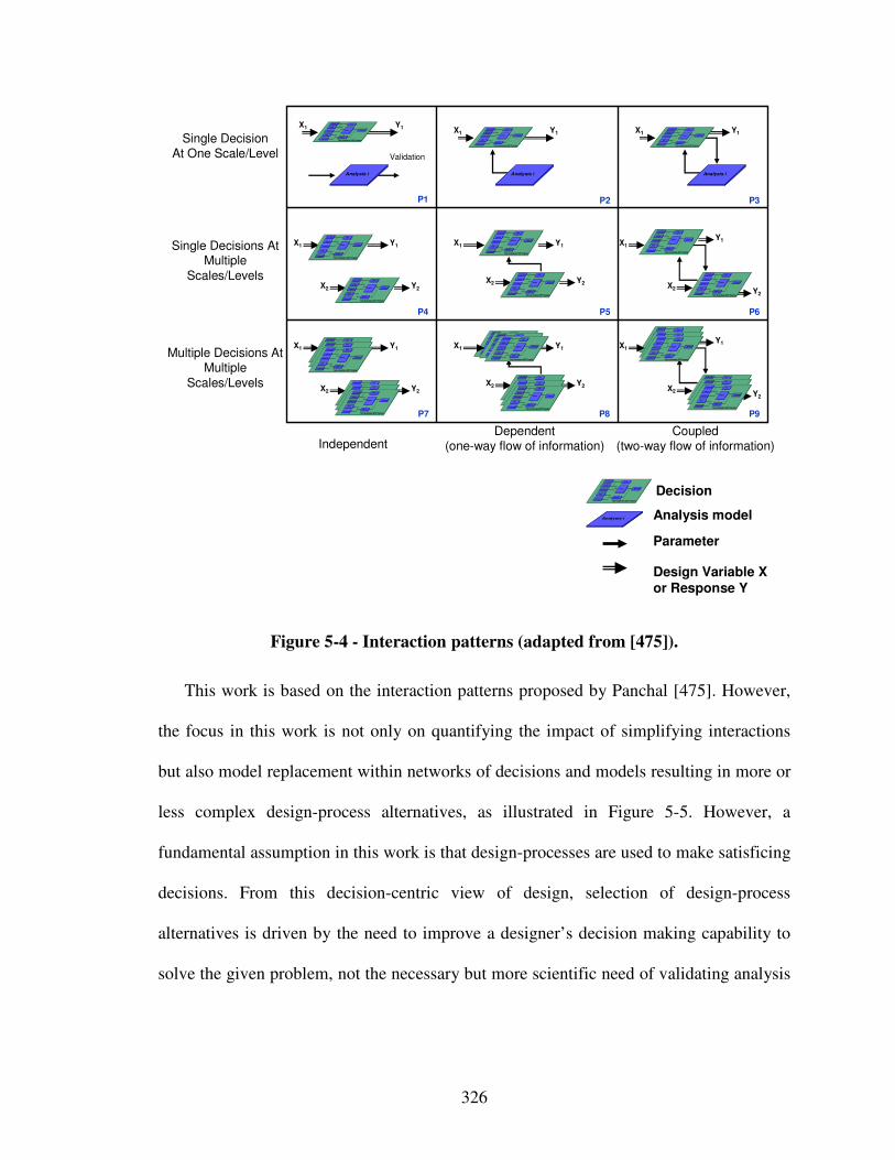
326
Goals
Pref erences
Variables
Parameters
Const raints
Response
Objective
Fully Instantiated cDSP Template
Driver
Analysis
Goals
Pref erences
Variables
Parameters
Const raints
Response
Objective
Fully Instantiated cDSP Template
Driver
Analysis
Single Decisions At Multiple
Scales/Levels
Single DecisionAt One Scale/Level
IndependentDependent
(one-way flow of information)Coupled
(two-way flow of information)
P1 P2 P3
P6
P9P8P7
P4 P5
Validation
X1 Y1
X2 Y2
X1 Y1
X2 Y2
X1
Y1
X2 Y2
Multiple Decisions At Multiple
Scales/Levels
Analysis i
Goals
Preferences
Variables
Parameters
Constraints
Response
Objective
Fully Instantiated cDSP Template
Driver
Analysis
Goals
Preferences
Variables
Parameters
Constraints
Response
Objective
Fully Instantiated cDSP Template
Driver
Analysis
Analysis i
Goals
Preferences
Variables
Parameters
Constraints
Response
Objective
Fully Instantiated cDSP Template
Driver
Analysis
Analysis i
Goals
Pref erences
Variables
Parameters
Const raints
Response
Objective
Fully Instantiated cDSP Template
Driver
Analysis
X1 Y1 X1 Y1 X1 Y1
Goals
Pref erences
Variables
Parameters
Const raints
Response
Objective
Fully Instantiated cDSP Template
Driver
Analysis Goals
Pref erences
Variables
Parameters
Const raints
Response
Objective
Fully Instantiated cDSP Template
Driver
Analysis
Goals
Preferences
Variables
Parameters
Constraints
Response
Objective
Fully Instantiated cDSP Template
Driver
Analysis
Goals
Pref erences
Variables
Parameters
Const raints
Response
Objective
Fully Instantiated cDSP Template
Driver
Analysis
Goals
Pref erences
Variables
Parameters
Const raints
Response
Objective
Fully Instantiated cDSP Template
Driver
Analysis
X1 Y1
X2 Y2
X1 Y1
X2 Y2
X1
Y1
X2 Y2
Goals
Pref erences
Variables
Parameters
Const raints
Response
Objective
Fully Instantiated cDSP Template
Driver
Analysis
Goals
Pref erences
Variables
Parameters
Const raints
Response
Objective
Fully Instantiated cDSP Template
Driver
Analysis Goals
Pref erences
Variables
Parameters
Const raints
Response
Objective
Fully Instantiated cDSP Template
Driver
Analysis
Goals
Preferences
Variables
Parameters
Constraints
Response
Objective
Fully Instantiated cDSP Template
Driver
Analysis
Goals
Pref erences
Variables
Parameters
Const raints
Response
Objective
Fully Instantiated cDSP Template
Driver
Analysis
Goals
Pref erences
Variables
Parameters
Const raints
Response
Objective
Fully Instantiated cDSP Template
Driver
Analysis
Goals
Pref erences
Variables
Parameters
Const raints
Response
Objective
Fully Instantiated cDSP Template
Driver
Analysis
Goals
Pref erences
Variables
Parameters
Const raints
Response
Objective
Fully Instantiated cDSP Template
Driver
Analysis
Goals
Pref erences
Variables
Parameters
Const raints
Response
Objective
Fully Instantiated cDSP Template
Driver
Analysis
Goals
Pref erences
Variables
Parameters
Const raints
Response
Objective
Fully Instantiated cDSP Template
Driver
Analysis
Goals
Pref erences
Variables
Parameters
Const raints
Response
Objective
Fully Instantiated cDSP Template
Driver
Analysis
Goals
Pref erences
Variables
Parameters
Const raints
Response
Objective
Fully Instantiated cDSP Template
Driver
Analysis
Goals
Pref erences
Variables
Parameters
Const raints
Response
Objective
Fully Instantiated cDSP Template
Driver
Analysis Goals
Pref erences
Variables
Parameters
Const raints
Response
Objective
Fully Instantiated cDSP Template
Driver
Analysis
Goals
Pref erences
Variables
Parameters
Const raints
Response
Objective
Fully Instantiated cDSP Template
Driver
Analysis
Goals
Pref erences
Variables
Parameters
Const raints
Response
Objective
Fully Instantiated cDSP Template
Driver
Analysis
Decision
Analysis model
Parameter
Design Variable X or Response Y
Analysis i
Goals
Preferences
Variables
Parameters
Constraints
Response
Objective
Fully Instantiated cDSP Template
Driver
Analysis
Figure 5-4 - Interaction patterns (adapted from [475]).
This work is based on the interaction patterns proposed by Panchal [475]. However,
the focus in this work is not only on quantifying the impact of simplifying interactions
but also model replacement within networks of decisions and models resulting in more or
less complex design-process alternatives, as illustrated in Figure 5-5. However, a
fundamental assumption in this work is that design-processes are used to make satisficing
decisions. From this decision-centric view of design, selection of design-process
alternatives is driven by the need to improve a designer’s decision making capability to
solve the given problem, not the necessary but more scientific need of validating analysis
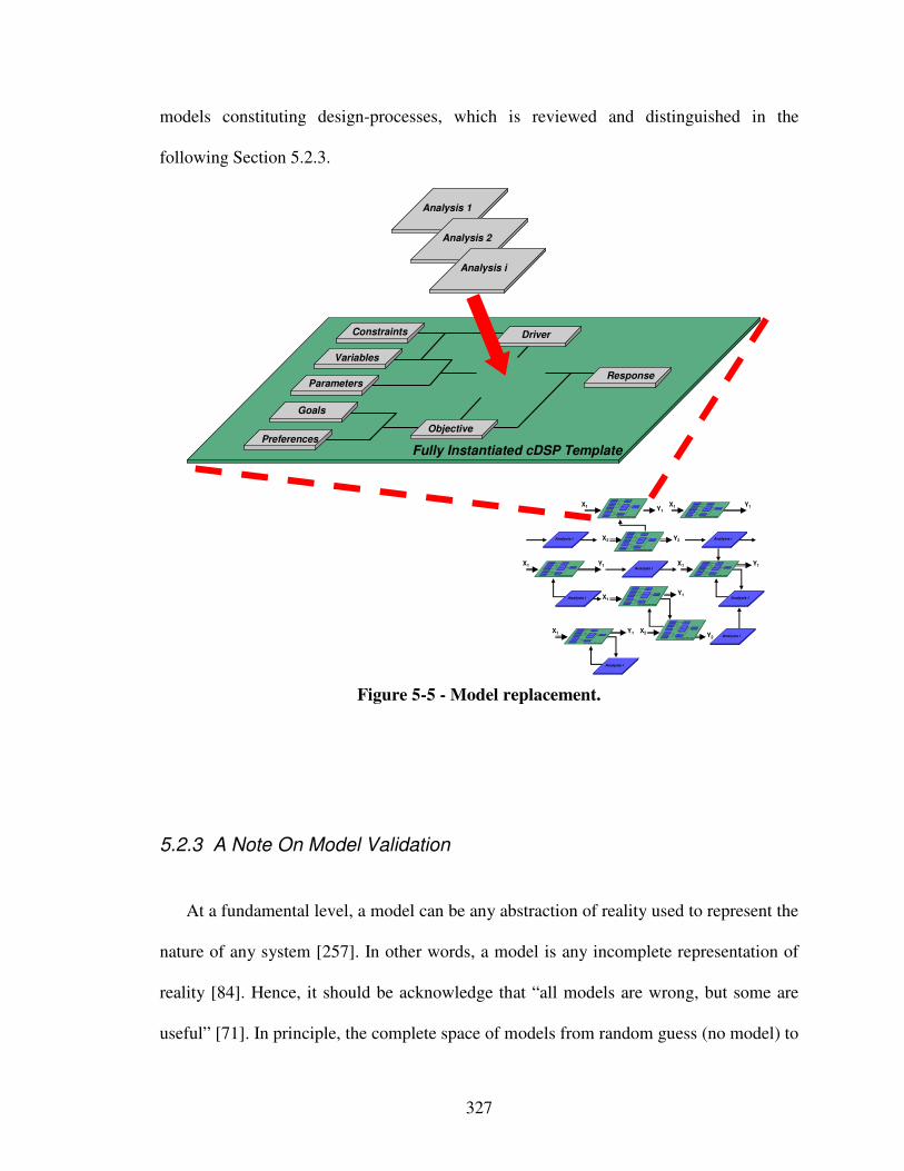
327
models constituting design-processes, which is reviewed and distinguished in the
following Section 5.2.3.
Goals
Preferences
Variables
Parameters
Constraints
Response
Objective
Analysis 1
Fully Instantiated cDSP Template
Driver
Analysis 2
Analysis i
X1 Y1
X2 Y2
X1
Y1
X2 Y2
Analysis i
Goals
Preferences
Variables
Parameters
Constraints
Response
Objective
Fully Instantiated cDSP Template
Driver
Analysis
Goals
Preferences
Variables
Parameters
Constraints
Response
Objective
Fully Instantiated cDSP Template
Driver
Analysis
Analysis i
Goals
Preferences
Variables
Parameters
Constraints
Response
Objective
Fully Instantiated cDSP Template
Driver
Analysis
Analysis i
X1 Y1
X1 Y1 X1 Y1
Goals
Preferences
Variables
Parameters
Constraints
Response
Objective
Fully Instantiated cDSP Template
Driver
Analysis
Goals
Preferences
Variables
Parameters
Constraints
Response
Objective
Fully Instantiated cDSP Template
Driver
Analysis
Goals
P references
Variables
Parameters
Constraints
Response
Objective
Fully Instant iated cDSP Template
Driver
Analysis
Goals
P references
Variables
Parameters
Constraints
Response
Objective
Fully Instant iated cDSP Template
Driver
Analysis
Goals
P references
Variables
Parameters
Constraints
Response
Objective
Fully Instant iated cDSP Template
Driver
Analysis
Analysis i
X1 Y1
Analysis i
Analysis i
Analysis i
Figure 5-5 - Model replacement.
5.2.3 A Note On Model Validation
At a fundamental level, a model can be any abstraction of reality used to represent the
nature of any system [257]. In other words, a model is any incomplete representation of
reality [84]. Hence, it should be acknowledge that “all models are wrong, but some are
useful” [71]. In principle, the complete space of models from random guess (no model) to
328
the actual product or “build-it-to-model-it” model is possible. The premise that a more
truthful model can always be constructed must be considered. In this work, only an
instance of the final product may be considered an equivalent of truth [524]. Hence, the
focus in this work is on evaluating simulation-based design-process alternatives, where
the decisions and models can be formulated mathematically and solved computationally,
to design-process alternatives comprised of the most truthful analysis models available.
In the past few decades, significant efforts have focused on i) developing accurate
analysis models for various aspects of a complex system, and ii) high performance
computing tools to support these complex models. In spite of the significant progress in
both these areas, modeling all aspects of a complex system in a simulation model is not
possible using available computational resources. Thus, the goal in this work is to
manage complexity by identifying satisficing design-process alternatives from a decision-
centric perspective. The goal is not to increase scientific knowledge or validate analysis
models constituting design-processes as reviewed in the following.
Model validation has been defined as the “substantiation that a computerized model
within its domain of applicability possesses a satisfactory range of accuracy consistent
with the intended application of the model [569]. Model validation typically runs
concurrent to model development [565]. General guidelines for achieving model validity
are: a) define problem, b) validate input data, c) build conceptual model, d) validate
conceptual model, e) build computerized model, f) verify computerized model, g),
validate output data from experiments, and h) validate behavior of computerized model.
However, many approaches for model validation have been reported in the literature.
329
For example, Sargent [565] developed a validation procedure in and between
conceptual, computerized, and operational models and data for developing valid
simulation models. Also, Malak and Paredis describe a general process for performing
model validation for reused behavioral models [387]. Specifically, they decompose
model validation into three core activities: a) validity characterization, i.e., the process of
developing a validity description, b) compatibility assessment, i.e., the process of
establishing validity of the context of a behavioral model, and c) adequacy assessment,
i.e., the process of establishing validity of the uncertainty of a behavioral model.
However, it is also recognized that in addition to validating behavioral models, one must
also validate the predictions generated from them.
As discussed by Malak and Paredis [385, 387], “model validation is about bringing
together various sources of validation-relevant knowledge, including knowledge about a
model’s domain of applicability, range of accuracy, simplifying assumptions, decision
context, and intended application. Theoretically, “model validation is a subjective,
scientific process that is open to refutation but not positive justification” [387]. In this
context, designers must remember that ‘subjective’ does not imply ‘arbitrary’ or
‘unsupported’. At the same time, no amount of data can “prove” a model to be valid. This
is a direct consequence of a classical problem in philosophy, known as the problem of
induction [284]. As stated by Malak and Paredis [384], to proved deductively that a
continuous model is valid, one would require an infinite amount of empirical data.
Especially in the integrated design of products and materials, experimental
measurements are a key component of model validation. Also, experimental
measurements are performed to i) provide input to models, ii) augment or replace models
330
with measured data, or iii) calibrate models. However, the validation is more
comprehensive and includes internal consistency, applicability ranges, implementation,
etc. But, since experimental are a key component in integrated materials design, and
hence frequently available or relatively easy to generate for designers. Accepting a
model’s validity, this experimental data can hence be leveraged to assess the value of a
specific model to the decision maker – the key to manage complexity and thereby
increase a designer’s design-process flexibility.
A fundamental assumption in this work is that the analysis models constituting
design-processes have been validated. Hence, the focus in this work is not on validation,
but evaluating the value of design-process alternatives to a designer in a given problem
context from a decision-centric design perspective. Seldom it is desirable for engineers to
use the most precise model available, as reducing systematic or random model errors
(random model errors are often due to variability in the model parameters and initial and
boundary conditions) typically costs more in terms of development and computational
expense. A designer however almost always seeks to use the least expensive design-
process alternative that is adequate for decision making to solve the given problem.
The threshold defining adequacy is subject to one’s value judgment. The choice of an
appropriate model may depend on specific characteristics of the decision at hand,
including the preference of a designer, the uncertainty in other problem parameters, and
the importance of the decision. Since a decision maker is often conservative, a design-
process alternative is acquired and used that is more accurate then is really required,
unnecessarily spending additional resources. Hence, information economics tradeoffs as

331
explored in the following sections have been investigated in the context of designing
design-processes.
5.2.4 Managing Complexity Using Value-Of-Information-based Metrics
Information economics, as reviewed in detail in Section 2.3.5, is used to study the
effect of information on decisions. Information economics tradeoffs are quantified by
various “value-of-information” metrics. The idea of using a value-of-information-based
approach for determining whether to consider additional information for decision making
is not new. It was first introduced by Howard [274]. The expected value-of-information
as defined by Howard is “the difference between the expected value of the objective for
the option selected with the benefit of the information less than without”. As described by
Panchal [475], two types of definitions for value of information are particularly important
in the information economics literature, reviewed in detail in Section 2.3.5. These include
“ex-post value-of-information”, and “ex-ante value-of-information” [361]. Ex-post value-
of-information is evaluated by measuring the difference in payoff before and after the
realization of states of variable x (but after the decision has been made in both cases). Ex-
ante value of information refers to the difference in the expected payoff before and after
gathering additional information. Mathematically, the ex-post and ex-ante value of
information are represented as follows:
• Ex-post value: ν(x, y) = π(x, ay) – π(x, a0), where, a0 and ay represent the actions
taken by decision maker in the absence and presence of information y. π(x, a)
332
represents the payoff achieved by selecting an action a, when the state realized by
the environment is x.
• Ex-ante value: ν(x, y) = Ex│yπ(x, ay) – Exπ(x, a0), where Exf(x) is the expected
value of f(x) and Ex│yf(x) is the expected value of f(x) given y. It is important to
realize that the key difference between ex-post and ex-ante value is that in ex-post
value, the realization of state x is known. However, the realization of state x is not
known in ex-ante value and the expected value of payoff is taken over the
uncertain range of state x.
Ideally, the designers are interested in the ex-post value of information because it
truly reflects the value-of-information for a decision based on the actual behavior of the
system. However, it is not possible to calculate the ex-post value of decision before
making the decision itself. Due to the ex-ante nature of decision making, the decisions
about the information have to be made before the state actually occurs. Hence, the ex-
ante value of information is generally used by designers. It captures the value of
information by considering uncertainties in the system. These uncertainties result from
simplifying design-processes or using a simplified design-process alternative in the first
place. Thus, ex-ante value of information is used to quantify the effect of simplifying
design-processes or using simplified design-process alternatives in the first place. If this
effect has a limited impact on a designer’s decision making capability, then, the currently
instantiated design-process alternative is appropriate.
To identify an appropriate design-process alternative, many researchers have focused
on simplifying interaction couplings in networks of decisions and models. The commonly
used approach to simplification of couplings is to decompose the system level problem
333
into independent sub-problems by either re-sequencing tasks (if there is no coupling) or
identifying and removing weak couplings. Various researchers have quantified the
strength of couplings in different ways. Pimmler and Eppinger [502] present a five point
scale (+2, +1, 0, -1, and -2) to represent the strength of couplings. Kusiak and Park [351]
present a binary incidence matrix (with modules as rows and activities as columns) for
decomposition of design activities. Chen and coauthors [105-107] present a similar
binary incidence matrix with attributes (functions) as rows and components (design
parameters) as columns. Later, Li and Chen [369] extend the binary incidence matrix to a
non-binary Design Dependency Matrix (DDM), where the elements of the matrix
quantify the sensitivity of a function due to parameter changes.
Also, the sensitivity-based approach to quantifying coupling strength for
decomposition has been widely used in the Multidisciplinary Analysis and Optimization
(MAO) literature. Sobieski [619] has proposed an approach for determining sensitivity of
system level outputs to system level inputs using Global Sensitivity Equations (GSEs),
which are foundational for various efforts on decomposition [64, 65, 182, 247, 283, 549].
English and coauthors [185] have extended the Global Sensitivity based approach to
estimate the impact of coupling suspension on multiple cycles.
Although these approaches provide a means for simplifying couplings, their
effectiveness reduces when a) networks of decisions and models are complex, b) the
changes in the design variables are high, and c) the objective function is highly non-linear
or discontinuous. In order to address the limitations of existing approaches, value-of-
information-based metrics have been used to identify an appropriate design-process
alternative [472]. If evaluation of a value-of-information-based metric shows that a
334
designer’s objectives are met and the potential benefits by adding more information to the
system is not likely to improve the design decision, the evaluated design-process
alternative is appropriate for designing.
Various efforts have been carried out to utilize value-of-information-based metrics in
engineering design. For example, Agogino and coauthors [12, 74, 75, 733] present a
metric called the Expected Value of Information (EVI) and use it for a catalog selection
problem [74] in the conceptual design phase [470]. The EVI is equal to the expectation of
objective function over the uncertain variables with new information minus the
expectation of the objective function with current state of information. Poh and Horvitz
[506] use a value-of-information metric for refining decisions in the following three
dimensions – quantitative, conceptual, and structural. The authors use the value-of-
information metric to determine which dimension is critical for refinement of the decision
problem. However, in previous research efforts by Howard [274], Agogino & coauthors
[74], and Lawrence [361] the value of information is calculated by considering only the
stochastic variability, where the decision can be made by maximizing the expected value
of the objective function.
In order to model uncertainty for evaluating value-of-information, it has generally
been assumed that the precisely characterized joint and conditional probability
distributions are available. If these probability distributions are not available, approaches
have been proposed to generate those through an educated guess that is based on the
designers’ prior knowledge. Also, in order to address the problem of lack of knowledge
about the probability distributions, Aughenbaugh and co-authors [32] present an
approach of measuring the value of information based on probability bounds on the value
335
of information that are calculated by a designer during the information collection process
using imprecise probabilities. Hence, imprecise probabilities are used to establish bounds
on the value of future statistical data sample collection. They assume that although the
exact probability distributions are unavailable, the lower and upper bounds on these
probability distributions are available in terms of p-boxes. Using this p-box approach,
they evaluate the value of added information that reduces the size of the interval for
probability distribution (i.e., tightens the bounds on the p-box).
The aforementioned efforts do not address the case of decision making under
uncertainty that cannot be represented using probability functions. However, Ling and
Paredis [373] present a value-of-information-based approach for model selection for the
particular scenario in which the systematic error in the models can be bounded by an
interval. However, the underlying assumption is that an interval-based characterization of
the error in model output is truthful and available throughout the whole design space.
Furthermore, error bounds do not necessarily indicate anything about a model’s
usefulness. Also, Doraiswamy and Krishnamurty [169], Radhakrishnan and McAdams
[524] or Cherkassky [121] consider cost-benefits trade-offs in selecting models of various
levels of abstraction in engineering design. They present a utility-based framework in
which a designer can reason about model uncertainty assuming a perfect model is
available. This perfect model is then used as a benchmark for rating other possible model
alternatives.
Also, Panchal and coauthors [484] present a value-of-information based metric called
Improvement Potential to account for the non-probabilistic uncertainty resulting from
simplification of interactions between models and decisions. The improvement potential
336
is quantified as Pi =max(Umax)- (Umin)*, where max(Umax) is the maximum expected
payoff that can be achieved by any point in the design space and (Umin)* is the lowest
expected payoff value achieved by the selected point in the design space (after making
the decision without added information). Similarly to the approaches reviewed above, the
Improvement Potential metric is based on the assumption that information about bounds
on utility (i.e., the lower and upper bounds on the overall system outcome) is available
globally, i.e., throughout the whole design space. The reliance on lower and upper bounds
for the use of metric currently restricts its use for the specific cases where information
about these bounds is unavailable. Hence, scenarios where this information is unavailable
are not handled using the metric.
5.2.5 Research Gap Analysis
In various circumstances, especially in the context of integrated product and materials
design on multiple levels and scales, a designer has access to different kinds of analysis
models constituting design-process alternatives that embody different assumptions, but,
the error bounds on those models are unavailable throughout the whole design-space. In
the context of integrated product and materials design, it is not practically feasible to
either know a model’s error or associated probability bounds throughout the whole design
space or generate those through an “educated guess” in terms of p-boxes. Also, it is not
considered feasible to know the behavior of a most truthful model throughout the whole
design space.
337
For example, consider a scenario in which multiple simulation models that embody
different mathematical models for the same physical phenomena predicting the same
response value are available. All the models have some level of imprecision but the most
accurate model is unknown. Hence, for each model, the information about the upper and
lower bounds of error is not available. Also, some of these models might even embody
different assumptions or require different configurations between decisions or other
analysis models, making the assumption of availability of information about the upper
and lower bounds of error even less feasible. Hence, for these scenarios, the current
value-of-information-based metrics need to be extended.
Also, in most engineering scenarios, system behavior is predicted through
experimentation, prototype or specimen testing, or evaluation of extremely
computationally expensive design-process alternatives. This is specially true in the
context of integrated product and materials design. Due to uncertainty about many
physical phenomena spanning various length and time scales, simulation is extremely
computationally expensive and experimentation is a generally accepted modeling
technique. Materials design differs significantly from the more traditional design
problem, in which the component behavior is often well known or can be described by
relatively simple models [327]. However, materials design enjoys the advantage of
availability of rich pools of material data due to experimentation. Also, various methods
exists to predict the behavior of system components based on standardized or custom-
made specimen test data. This however, is only feasible at isolated points in the design
space. Hence, the assumption of existing value-of-information-based metrics that a
model’s error or associated probability bounds are truthful and available globally, i.e.,
338
throughout the whole design, is not valid in most integrated product and materials design
scenarios.
Further, the assumption of aforementioned approaches is that designers have the
knowledge of a complete network of decisions and analysis models, which is first
simplified and then sequentially refined again. Based on this knowledge, the least
complex network configuration is executed first. Then, the network configuration is
sequentially refined and evaluated until a satisficing design-process alternative is
achieved. However, this is a significant limitation in the integrated design of product and
materials on multiple levels and scales, because the number of interactions is
significantly higher than in conventional product design, and the number of network
configurations prohibits the sequential exploration of design-process alternatives. Also,
despite the rapid progress of computer technology, product and design-process
complexity is continuously increasing. Hence, due to the number of interactions and
design-process alternatives in the integrated product and materials design on multiple
levels and scales, knowledge of the complete network of decisions and analysis models
upfront as well as sequential exploration of design-process alternatives is prohibited.
For example, consider the Improvement Potential Metric proposed by Panchal [478].
This Improvement Potential Metric is based on design-process simplification, more
specifically decoupling interactions between complex simulation models on multiple
levels or scales to find a satisficing level of simplification. The Process Performance
Indicator on the other hand is focused on model replacement to identify a satisficing
design-process alternative. It is used to quantify the effect of refining a design-process
through model replacement and evaluate design-process alternatives. The starting point
339
when using the Process Performance Indicator does not need to be an already developed
complex design-process, that is first simplified and then sequentially refined.
Nevertheless, local performance information of a most truthful design-process must be
available. However, this information can be readily obtained through for example
experimenting – a practically feasible common and valid practice in integrated product
and materials design – or simulating very detailed finite element analyses at specific
points in the design space. This local information then makes the assumption of having
global information for evaluating the performance of design-processes obsolete.
In order to address the aforementioned limitations and challenges, summarized in
Table 1-5 and illustrated in Table 5-3, in the context of integrated product and materials
design a strategy to systematic design-process generation and selection from a systems
perspective including a value-of-information-based Process Performance Indicator is
developed. In this work, this generally applicable strategy is applied in the context of
integrated product and materials design. Having determined a principal solution in the
given problem context based on phenomena and associated solution principles, this
strategy is used to determine an appropriate embodiment design-process through stepwise
refinement / simplification of interactions or analysis models. Stepwise refinement /
simplification of interactions or analysis models for example translates to including /
excluding specific phenomena or associated solution principles on finer scales in the
context of integrated product and materials design if required for solution finding.
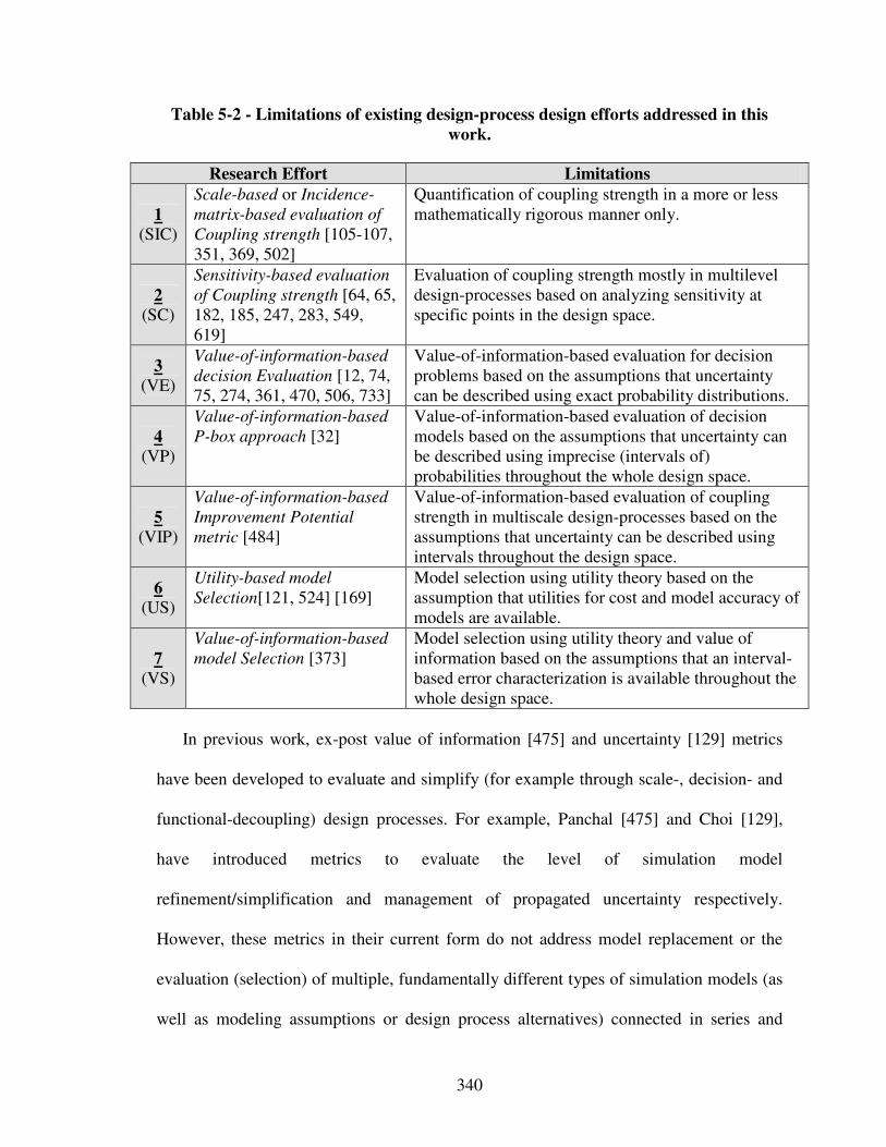
340
Table 5-2 - Limitations of existing design-process design efforts addressed in this
work.
Research Effort Limitations
1 (SIC)
Scale-based or Incidence-
matrix-based evaluation of
Coupling strength [105-107, 351, 369, 502]
Quantification of coupling strength in a more or less mathematically rigorous manner only.
2 (SC)
Sensitivity-based evaluation
of Coupling strength [64, 65, 182, 185, 247, 283, 549, 619]
Evaluation of coupling strength mostly in multilevel design-processes based on analyzing sensitivity at specific points in the design space.
3 (VE)
Value-of-information-based
decision Evaluation [12, 74, 75, 274, 361, 470, 506, 733]
Value-of-information-based evaluation for decision problems based on the assumptions that uncertainty can be described using exact probability distributions.
4 (VP)
Value-of-information-based
P-box approach [32] Value-of-information-based evaluation of decision models based on the assumptions that uncertainty can be described using imprecise (intervals of) probabilities throughout the whole design space.
5 (VIP)
Value-of-information-based
Improvement Potential
metric [484]
Value-of-information-based evaluation of coupling strength in multiscale design-processes based on the assumptions that uncertainty can be described using intervals throughout the design space.
6 (US)
Utility-based model
Selection[121, 524] [169] Model selection using utility theory based on the assumption that utilities for cost and model accuracy of models are available.
7 (VS)
Value-of-information-based
model Selection [373] Model selection using utility theory and value of information based on the assumptions that an interval-based error characterization is available throughout the whole design space.
In previous work, ex-post value of information [475] and uncertainty [129] metrics
have been developed to evaluate and simplify (for example through scale-, decision- and
functional-decoupling) design processes. For example, Panchal [475] and Choi [129],
have introduced metrics to evaluate the level of simulation model
refinement/simplification and management of propagated uncertainty respectively.
However, these metrics in their current form do not address model replacement or the
evaluation (selection) of multiple, fundamentally different types of simulation models (as
well as modeling assumptions or design process alternatives) connected in series and
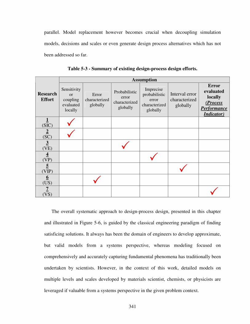
341
parallel. Model replacement however becomes crucial when decoupling simulation
models, decisions and scales or even generate design process alternatives which has not
been addressed so far.
Table 5-3 - Summary of existing design-process design efforts.
Assumption
Research
Effort
Sensitivity or
coupling evaluated
locally
Error characterized
globally
Probabilistic error
characterized globally
Imprecise probabilistic
error characterized
globally
Interval error characterized
globally
Error
evaluated
locally
(Process
Performance
Indicator)
1 (SIC)
2 (SC)
3 (VE)
4 (VP)
5 (VIP)
6 (US)
7 (VS)
The overall systematic approach to design-process design, presented in this chapter
and illustrated in Figure 5-6, is guided by the classical engineering paradigm of finding
satisficing solutions. It always has been the domain of engineers to develop approximate,
but valid models from a systems perspective, whereas modeling focused on
comprehensively and accurately capturing fundamental phenomena has traditionally been
undertaken by scientists. However, in the context of this work, detailed models on
multiple levels and scales developed by materials scientist, chemists, or physicists are
leveraged if valuable from a systems perspective in the given problem context.
342
The underlying philosophy in this research though is best expressed by a famous
quote from Albert E. Einstein: “Everything should be made as simple as possible, but not
simpler”. Therefore, it is proposed to develop and evaluate less complex design-
processes based on “simple” analysis models first before investing in additional modeling
– in other words to proceed from the qualitative (approximate) to the quantitative
(detailed), instead of building a complex model first and then step by step simplifying it
as it has been done before. Hence, design-process alternatives are to be evaluated based
on information economical indices taking into account designers’ preferences from a
decision-centric systems perspective first before additional modeling resources are
allocated and the decision on a specific embodiment design-process is made. Starting
with a less complex design-process alternative, more refined design-process alternatives
are generated systematically based on refined modeling or coupling of the scientific
phenomena and associated solution principles identified beforehand only after the current
design-process alternative has been evaluated.
Building on the interaction matrix concept introduced by Panchal and concepts in
information economics, current design-process design techniques are extended by
developing a value-of-information-based indicator to evaluate systematically generated
integrated product and materials design-process alternatives from a systems perspective.
By doing so, not only model refinement/simplification, but also model replacement with
fundamentally different models can be evaluated before additional modeling resources
are allocated. Evaluating simulation model refinement or replacement with fundamentally
different types of models is a scenario that for example frequently occurs in integrated
343
product and materials design when decoupling scales or refining design-process
alternatives and simulation models from a systems perspective.
As discussed by Choi [129], uncertainty is associated with model-based predictions
for several reasons, one of them being that models inevitably incorporate assumptions
and approximations that impact the precision and accuracy of predictions. “Tightening”
assumptions and approximations may or may not increase the value of information on the
system level. Therefore, it is proposed to analyze design-process performance before
additional modeling resources are allocated in order to instantiate a satisficing design
process. The value-of-information-based indicator developed in this work is an indirect
index, i.e., an index related to direct metrics such as cost and time but more suitable to
the early design phases characterized by more or less incomplete, varying and mostly
qualitative information.
Foundational to the design-process design strategy developed in this work is to
proceed from the qualitative (approximate simulation model) to the quantitative (detailed
simulation model), instead of building a complex model first and then step by step
simplifying it as it has been done before. Starting with a less complex design-process
alternative, more refined design-process alternatives are generated systematically based
on refined modeling or coupling of the scientific phenomena and associated solution
principles identified beforehand only after the current design-process alternative has been
evaluated. However, the value-of-information-based strategy to design-process
generation and selection is described in greater detail after the proposed value-of-
information-based Process Performance Indicator has been developed in the following
section.

344
An overview of the systematic approach to embodiment design-process design
developed in this chapter is illustrated in Figure 5-6. In a first step, the value-of-
information-based metric is developed in Section 5.3. The strategy to embodiment
design-process generation and selection in which it is embedded is then described in
Section 5.4. Finally, limitations and opportunities of future work are discussed in Seciton
5.5 along with verification and validation addressed in Section 5.6. Empirically, the
constructs developed in this Chapter are validated using the reactive material containment
system example and optoelectronic system example in Chapters 7 and 8 respectively.
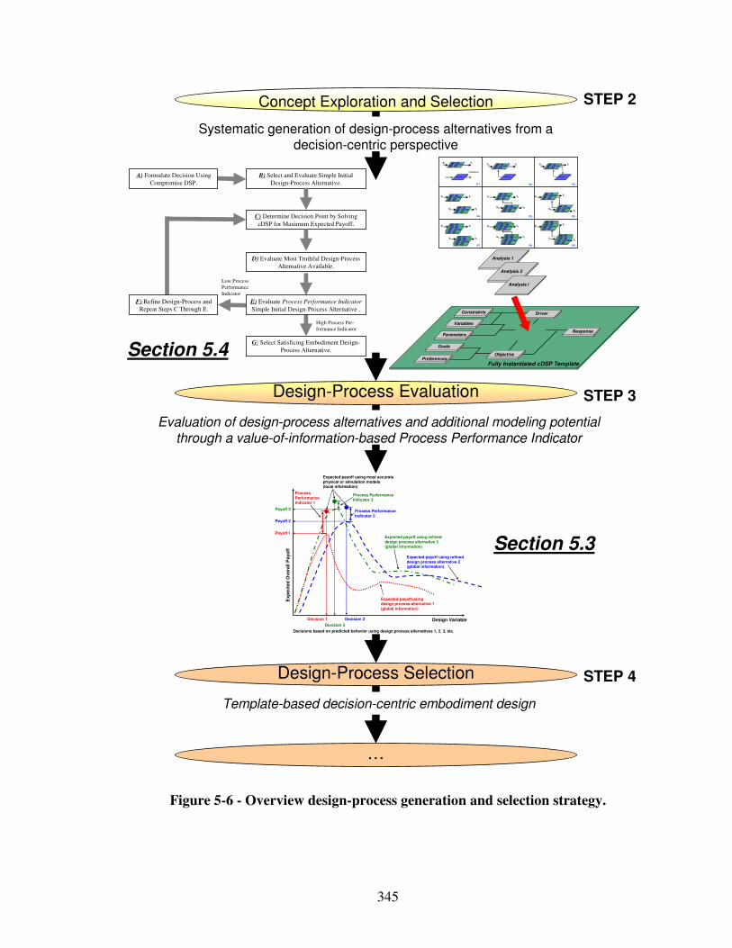
345
Evaluation of design-process alternatives and additional modeling potential through a value-of-information-based Process Performance Indicator
Systematic generation of design-process alternatives from a decision-centric perspective
Design-Process Evaluation
Design-Process Selection
Concept Exploration and Selection
Template-based decision-centric embodiment design
Design Variable
Exp
ecte
d O
vera
ll P
ayo
ff
Expected payoff usingdesign process alternative 1(global information)
Expected payoff using refined design process alternative 2(global information)
Payoff 2
Decision 1 Decision 2
Payoff 1
Process Performance Indicator 1
Expected payoff using most accurate physical or simulation models(local information)
Process Performance Indicator 2
Decisions based on predicted behavior using design process alternatives 1, 2, 3, etc.
Process Performance Indicator 3
Expected payoff using refined design process alternative 3(global information)
Payoff 3
Decision 3
…
Go als
P referenc es
Vari abl es
Pa ra meters
Con strain ts
Re spo nse
Obj ect i ve
Fully Instantia ted cDSPTemplate
D ri ver
A nal ysi s
Go als
P referenc es
Vari abl es
Pa ra meters
Con strain ts
Re spo nse
Obj ect i ve
Fully Instantia ted cDSPTemplate
D ri ver
A nal ysi s
P1 P2 P3
P6
P9P8P7
P4 P5
Validation
X1 Y1
X2 Y2
X1 Y1
X2 Y2
X1
Y1
X2 Y2
Analysis i
Go als
P referenc es
Vari abl es
Pa ra meters
Con strain ts
Re spo nse
Obj ect i ve
Fully Instantia ted cDSPTemplate
D ri ver
A nal ysi s
Go als
P referenc es
Vari abl es
Pa ra meters
Con strain ts
Re spo nse
Obj ect i ve
Fully Instantia ted cDSPTemplate
D ri ver
A nal ysi s
Analysis i
Go als
P referenc es
Vari abl es
Pa ra meters
Con strain ts
Re spo nse
Obj ect i ve
Fully Instantia ted cDSPTemplate
D ri ver
A nal ysi s
Analysis i
Go al s
Preferen ces
Va ri ab le s
P arameters
Co nstrai nts
Res pon se
Ob je ct ive
Fully Instantiated cDSP Template
Dri ver
An aly si s
X1 Y1 X1 Y1 X1 Y1
Go als
P referenc es
Vari abl es
Pa ra meters
Con strain ts
Re spo nse
Obj ect i ve
Fully Instantia ted cDSPTemplate
D ri ver
A nal ysi s Go als
P referenc es
Vari abl es
Pa ra meters
Con strain ts
Re spo nse
Obj ect i ve
Fully Instantia ted cDSPTemplate
D ri ver
A nal ysi s
Go als
P referenc es
Vari abl es
Pa ra meters
Con strain ts
Re spo nse
Obj ect i ve
Fully Instantia ted cDSPTemplate
D ri ver
A nal ysi s
Go als
P referenc es
Vari abl es
Pa ra meters
Con strain ts
Re spo nse
Obj ect i ve
Fully Instantia ted cDSPTemplate
D ri ver
A nal ysi s
Go als
P referenc es
Vari abl es
Pa ra meters
Con strain ts
Re spo nse
Obj ect i ve
Fully Instantia ted cDSPTemplate
D ri ver
A nal ysi s
X1 Y1
X2 Y2
X1 Y1
X2 Y2
X1
Y1
X2 Y2
Go al s
Preferen ces
Va ri ab le s
P arameters
Co nstrai nts
Res pon se
Ob je ct ive
Fully Instantiated cDSP Template
Dri ver
An aly si s
Go als
P referenc es
Vari abl es
Pa ra meters
Con strain ts
Re spo nse
Obj ect i ve
Fully Instantia ted cDSPTemplate
D ri ver
A nal ysi s Go als
P referenc es
Vari abl es
Pa ra meters
Con strain ts
Re spo nse
Obj ect i ve
Fully Instantia ted cDSPTemplate
D ri ver
A nal ysi s
Go als
P referenc es
Vari abl es
Pa ra meters
Con strain ts
Re spo nse
Obj ect i ve
Fully Instantia ted cDSPTemplate
D ri ver
A nal ysi s
Go als
P referenc es
Vari abl es
Pa ra meters
Con strain ts
Re spo nse
Obj ect i ve
Fully Instantia ted cDSPTemplate
D ri ver
A nal ysi s
Go als
P referenc es
Vari abl es
Pa ra meters
Con strain ts
Re spo nse
Obj ect i ve
Fully Instantia ted cDSPTemplate
D ri ver
A nal ysi s
Go al s
Preferen ces
Va ri ab le s
P arameters
Co nstrai nts
Res pon se
Ob je ct ive
Fully Instantiated cDSP Template
Dri ver
An aly si s
Go al s
Preferen ces
Va ri ab le s
P arameters
Co nstrai nts
Res pon se
Ob je ct ive
Fully Instantiated cDSP Template
Dri ver
An aly si s
Go als
P referenc es
Vari abl es
Pa ra meters
Con strain ts
Re spo nse
Obj ect i ve
Fully Instantia ted cDSPTemplate
D ri ver
A nal ysi s
Go als
P referenc es
Vari abl es
Pa ra meters
Con strain ts
Re spo nse
Obj ect i ve
Fully Instantia ted cDSPTemplate
D ri ver
A nal ysi s
Go als
P referenc es
Vari abl es
Pa ra meters
Con strain ts
Re spo nse
Obj ect i ve
Fully Instantia ted cDSPTemplate
D ri ver
A nal ysi s
Go als
P referenc es
Vari abl es
Pa ra meters
Con strain ts
Re spo nse
Obj ect i ve
Fully Instantia ted cDSPTemplate
D ri ver
A nal ysi s
Go als
P referenc es
Vari abl es
Pa ra meters
Con strain ts
Re spo nse
Obj ect i ve
Fully Instantia ted cDSPTemplate
D ri ver
A nal ysi s Go als
P referenc es
Vari abl es
Pa ra meters
Con strain ts
Re spo nse
Obj ect i ve
Fully Instantia ted cDSPTemplate
D ri ver
A nal ysi s
Go als
P referenc es
Vari abl es
Pa ra meters
Con strain ts
Re spo nse
Obj ect i ve
Fully Instantia ted cDSPTemplate
D ri ver
A nal ysi s
Go als
P referenc es
Vari abl es
Pa ra meters
Con strain ts
Re spo nse
Obj ect i ve
Fully Instantia ted cDSPTemplate
D ri ver
A nal ysi s
STEP 3
STEP 2
STEP 4
B) Select and Evaluate Simple Initial
Design-Process Alternative.
D) Evaluate Most Truthful Design-Process
Alternative Available.
G: Select Satisficing Embodiment Design-
Process Alternative.
A) Formulate Decision Using
Compromise DSP.
C) Determine Decision Point by Solving
cDSP for Maximum Expected Payoff.
High Process Per-
formance Indicator
Low Process
Performance
Indicator
E) Evaluate Process Performance Indicator
Simple Initial Design-Process Alternative .
F) Refine Design-Process and
Repeat Steps C Through E.
Goals
Preferences
Variables
Parameters
Constraints
Response
Objective
Analysis 1
Fully Instantiated cDSP Template
Driver
Analysis 2
Analysis i
Figure 5-6 - Overview design-process generation and selection strategy.
Section 5.3
Section 5.4
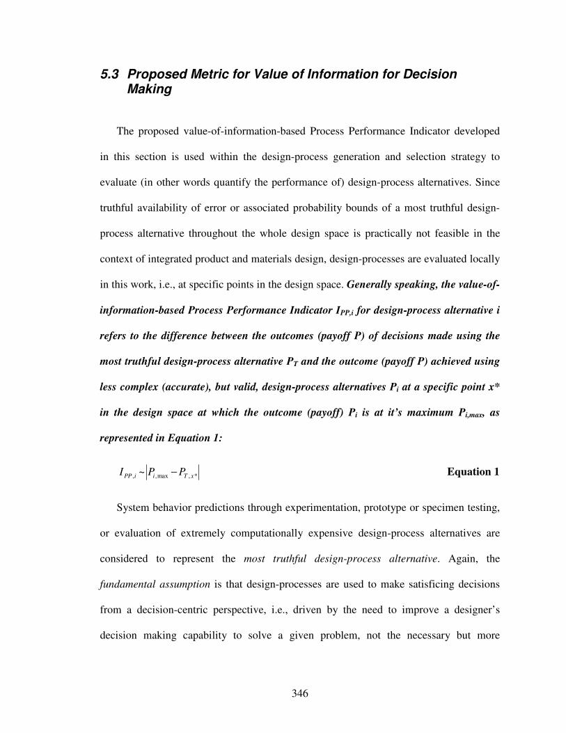
346
5.3 Proposed Metric for Value of Information for Decision Making
The proposed value-of-information-based Process Performance Indicator developed
in this section is used within the design-process generation and selection strategy to
evaluate (in other words quantify the performance of) design-process alternatives. Since
truthful availability of error or associated probability bounds of a most truthful design-
process alternative throughout the whole design space is practically not feasible in the
context of integrated product and materials design, design-processes are evaluated locally
in this work, i.e., at specific points in the design space. Generally speaking, the value-of-
information-based Process Performance Indicator IPP,i for design-process alternative i
refers to the difference between the outcomes (payoff P) of decisions made using the
most truthful design-process alternative PT and the outcome (payoff P) achieved using
less complex (accurate), but valid, design-process alternatives Pi at a specific point x*
in the design space at which the outcome (payoff) Pi is at it’s maximum Pi,max, as
represented in Equation 1:
*,max,, ~ xTiiPP PPI − Equation 1
System behavior predictions through experimentation, prototype or specimen testing,
or evaluation of extremely computationally expensive design-process alternatives are
considered to represent the most truthful design-process alternative. Again, the
fundamental assumption is that design-processes are used to make satisficing decisions
from a decision-centric perspective, i.e., driven by the need to improve a designer’s
decision making capability to solve a given problem, not the necessary but more
347
scientific need of validating analysis models constituting design-processes. However, the
outcome of a design-process is evaluated using a payoff function which depends on both a
chosen action a and the realized state of the world x. Because of uncertainty in the state of
the world x, the decision maker cannot know the outcomes or payoff of any action with
certainty. Hence, in this work, utility theory (as reviewed in detail in Section 2.1.2) for
decision making is used so that the decision maker maps model outputs into expected
utility.
Most of the “value-of-information” metrics are used to model the benefit achieved by
additional information only. Similarly, the approach developed in this work is based on
the premise that the appropriateness of a design-process depends on the impact on a
designer’s decisions. When more accurate analysis models comprising a more refined
design-process alternative are instantiated, it is equivalent to addition of information for
decision making. Value is measured in the context of system performance rather than in
absolute accuracy. Hence, design-process alternatives are selected on the basis of the
model’s overall benefit, payoff or utility to a designer [475]. If evaluation of the Process
Performance Indicator shows that a designer’s objectives are met and the potential
benefits by adding more information to the system is not likely to improve the design
decision, the evaluated design-process alternative is appropriate for designing.
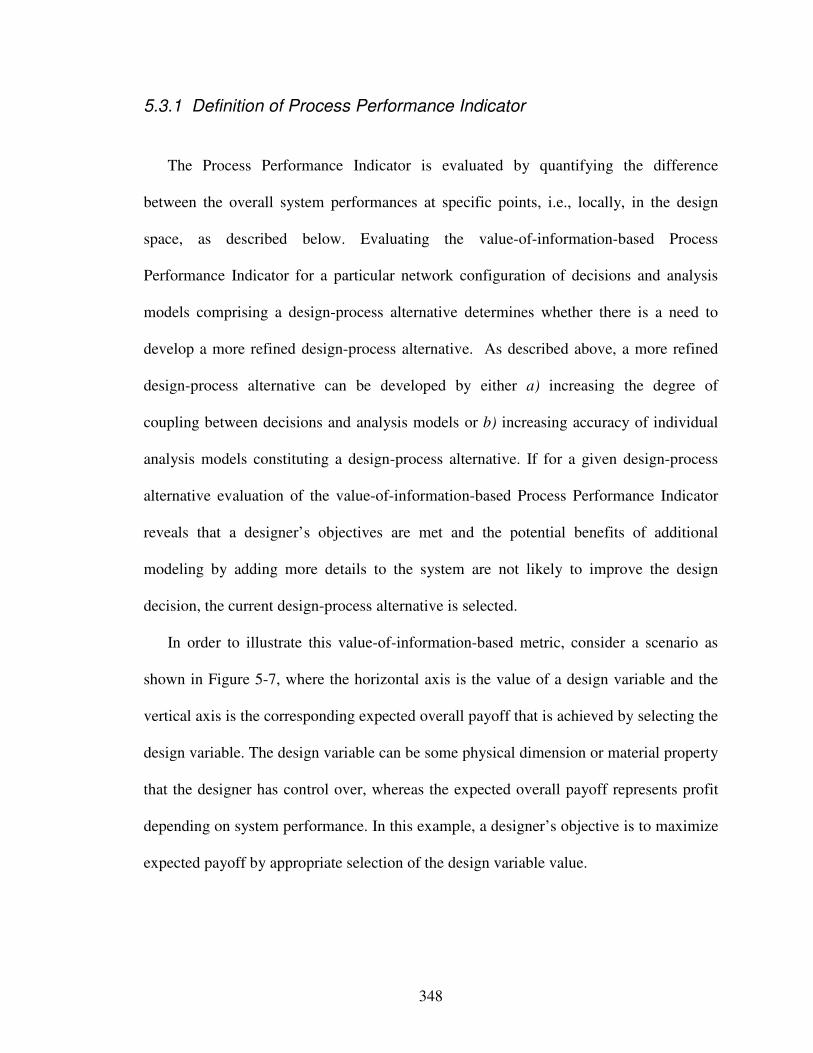
348
5.3.1 Definition of Process Performance Indicator
The Process Performance Indicator is evaluated by quantifying the difference
between the overall system performances at specific points, i.e., locally, in the design
space, as described below. Evaluating the value-of-information-based Process
Performance Indicator for a particular network configuration of decisions and analysis
models comprising a design-process alternative determines whether there is a need to
develop a more refined design-process alternative. As described above, a more refined
design-process alternative can be developed by either a) increasing the degree of
coupling between decisions and analysis models or b) increasing accuracy of individual
analysis models constituting a design-process alternative. If for a given design-process
alternative evaluation of the value-of-information-based Process Performance Indicator
reveals that a designer’s objectives are met and the potential benefits of additional
modeling by adding more details to the system are not likely to improve the design
decision, the current design-process alternative is selected.
In order to illustrate this value-of-information-based metric, consider a scenario as
shown in Figure 5-7, where the horizontal axis is the value of a design variable and the
vertical axis is the corresponding expected overall payoff that is achieved by selecting the
design variable. The design variable can be some physical dimension or material property
that the designer has control over, whereas the expected overall payoff represents profit
depending on system performance. In this example, a designer’s objective is to maximize
expected payoff by appropriate selection of the design variable value.
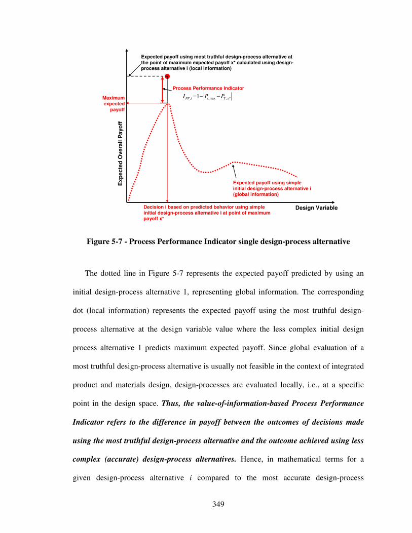
349
Design Variable
Exp
ecte
d O
vera
ll P
ayo
ff
Expected payoff using simpleinitial design-process alternative i(global information)
Decision i based on predicted behavior using simple initial design-process alternative i at point of maximum payoff x*
Maximumexpected
payoff
Process Performance Indicator
Expected payoff using most truthful design-process alternative at the point of maximum expected payoff x* calculated using design-process alternative i (local information)
*,max,, 1 xTiiPP PPI −−=
Figure 5-7 - Process Performance Indicator single design-process alternative
The dotted line in Figure 5-7 represents the expected payoff predicted by using an
initial design-process alternative 1, representing global information. The corresponding
dot (local information) represents the expected payoff using the most truthful design-
process alternative at the design variable value where the less complex initial design
process alternative 1 predicts maximum expected payoff. Since global evaluation of a
most truthful design-process alternative is usually not feasible in the context of integrated
product and materials design, design-processes are evaluated locally, i.e., at a specific
point in the design space. Thus, the value-of-information-based Process Performance
Indicator refers to the difference in payoff between the outcomes of decisions made
using the most truthful design-process alternative and the outcome achieved using less
complex (accurate) design-process alternatives. Hence, in mathematical terms for a
given design-process alternative i compared to the most accurate design-process
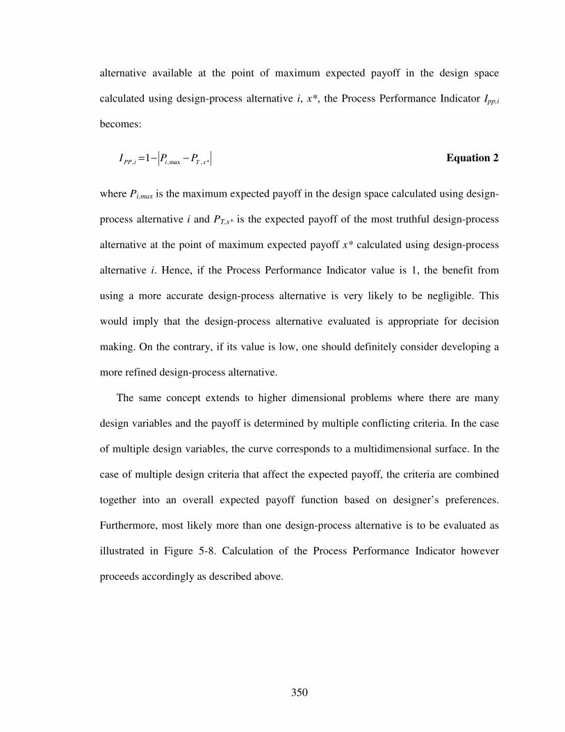
350
alternative available at the point of maximum expected payoff in the design space
calculated using design-process alternative i, x*, the Process Performance Indicator Ipp,i
becomes:
*,max,, 1 xTiiPP PPI −−= Equation 2
where Pi,max is the maximum expected payoff in the design space calculated using design-
process alternative i and PT,x* is the expected payoff of the most truthful design-process
alternative at the point of maximum expected payoff x* calculated using design-process
alternative i. Hence, if the Process Performance Indicator value is 1, the benefit from
using a more accurate design-process alternative is very likely to be negligible. This
would imply that the design-process alternative evaluated is appropriate for decision
making. On the contrary, if its value is low, one should definitely consider developing a
more refined design-process alternative.
The same concept extends to higher dimensional problems where there are many
design variables and the payoff is determined by multiple conflicting criteria. In the case
of multiple design variables, the curve corresponds to a multidimensional surface. In the
case of multiple design criteria that affect the expected payoff, the criteria are combined
together into an overall expected payoff function based on designer’s preferences.
Furthermore, most likely more than one design-process alternative is to be evaluated as
illustrated in Figure 5-8. Calculation of the Process Performance Indicator however
proceeds accordingly as described above.
351
Design Variable
Exp
ecte
d O
vera
ll P
ayo
ff
Expected payoff usingDesign-process alternative 1(global information)
Expected payoff using refined design-process alternative 2(global information)
ExpectedPayoff 2
Decision 1 Decision 2
ExpectedPayoff 1
Process Performance Indicator 1
Expected payoff using most truthful design-process alternative(local information)
Process Performance Indicator 2
Decisions based on predicted behavior using design process alternatives 1, 2, 3, etc.
Process Performance Indicator 3
Expected payoff using refined design-process alternative 3(global information)
ExpectedPayoff 3
Decision 3
Figure 5-8 - Process Performance Indicator multiple design-process alternatives
Evaluating of the Process Performance Indicator does not necessarily need to be
conducted at the global maximum of the expected payoff function as proposed above. On
the contrary, multiple points in the design space can and should be used to refine the
Process Performance Indicator evaluation. The designer has the freedom to choose the
number and locations at which the Process Performance Indicator is evaluated. When
using multiple points in the design space for evaluation, different strategies, so far
commonly used in response surface generation for metamodeling as reviewed in Section
2.3.4, may be leveraged. Those strategies may be as simple as for example a uniform
distribution or as elaborate as for example a sequential metamodeling techniques based
on maximizing entropy [372].
352
Examples of these guidelines that may be leveraged to identify the positioning of
evaluation points throughout the design space include classical methods ((Fractional)
Factorial, Central Composite, Box-Behnken, Alphabetical Optimal, Plackett-Burman),
space filling methods (Simple Grids, Latin Hypercobe, Orthogonal Array, Hammersley
Sequency, Uniform Designs, Minimax, and Maximin), hexagon methods, hybrid
methods, random selection (e.g., Monte Carlo method), human selection, importance
sampling, directional simulation, discriminative sampling, or sequential or adaptive
methods. Details on these guidelines derived from metamodeling strategies can be found
in the literature, such as [521, 603, 701], as reviewed in detail in Section 2.3.4.
Representative guidelines to sample the design space, i.e., evaluate the Process
Performance Indicator at multiple points in the design space, based on prominent
metamodeling techniques are summarized in Table 5-4. It is recommended to choose a
specific guidelines based on the problem and design space at hand.
When determining the Process Performance Indicator at multiple points in the design
space, it may be evaluated based on the maximum absolute difference or average of the
difference in expected payoff achieved comparing the most accurate design-process
alternative available with a less complex design-process alternative, depending on the
given scenario and the designer’s mindset. If a designer’s mindset is extremely
conservative or the design-problem at hand is characterized by extreme uncertainty,
scenario 1 – a worst-case scenario – is recommended. In scenario 2, a designer may
choose to use the mean of all Process Performance Indicators obtained. Besides the
arithmetic mean, other mean calculation may be considered, such as the geometric mean,
harmonic mean, etc. In scenario 3, a designer may weigh certain points at which the
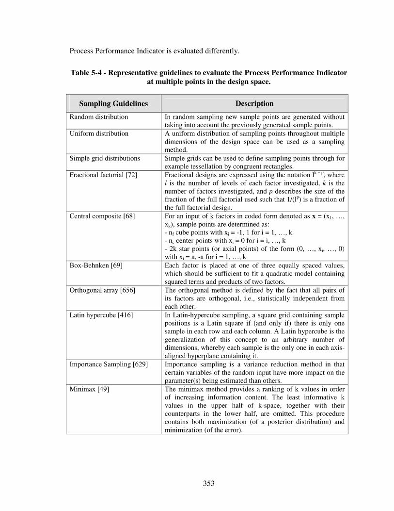
353
Process Performance Indicator is evaluated differently.
Table 5-4 - Representative guidelines to evaluate the Process Performance Indicator
at multiple points in the design space.
Sampling Guidelines
Description
Random distribution In random sampling new sample points are generated without taking into account the previously generated sample points.
Uniform distribution A uniform distribution of sampling points throughout multiple dimensions of the design space can be used as a sampling method.
Simple grid distributions Simple grids can be used to define sampling points through for example tessellation by congruent rectangles.
Fractional factorial [72] Fractional designs are expressed using the notation lk − p, where l is the number of levels of each factor investigated, k is the number of factors investigated, and p describes the size of the fraction of the full factorial used such that 1/(lp) is a fraction of the full factorial design.
Central composite [68] For an input of k factors in coded form denoted as x = (x1, …, xk), sample points are determined as: - nf cube points with xi = -1, 1 for i = 1, …, k - nc center points with xi = 0 for i = i, …, k - 2k star points (or axial points) of the form (0, …, xi, …, 0) with xi = a, -a for i = 1, …, k
Box-Behnken [69] Each factor is placed at one of three equally spaced values, which should be sufficient to fit a quadratic model containing squared terms and products of two factors.
Orthogonal array [656] The orthogonal method is defined by the fact that all pairs of its factors are orthogonal, i.e., statistically independent from each other.
Latin hypercube [416] In Latin-hypercube sampling, a square grid containing sample positions is a Latin square if (and only if) there is only one sample in each row and each column. A Latin hypercube is the generalization of this concept to an arbitrary number of dimensions, whereby each sample is the only one in each axis-aligned hyperplane containing it.
Importance Sampling [629] Importance sampling is a variance reduction method in that certain variables of the random input have more impact on the parameter(s) being estimated than others.
Minimax [49] The minimax method provides a ranking of k values in order of increasing information content. The least informative k values in the upper half of k-space, together with their counterparts in the lower half, are omitted. This procedure contains both maximization (of a posterior distribution) and minimization (of the error).
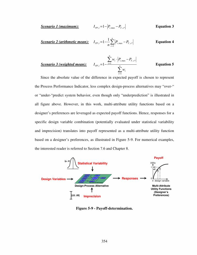
354
Scenario 1 (maximum): *,max,, 1 xTiiPP PPI −−= Equation 3
Scenario 2 (arithmetic mean): ∑=
−−=n
i
xTiiPP PPn
I1
*,max,,
11 Equation 4
Scenario 3 (weighted mean):
∑
∑
=
=
−⋅
−=n
i
i
n
i
xTii
iPP
w
PPw
I
1
1
*,max,
, 1 Equation 5
Since the absolute value of the difference in expected payoff is chosen to represent
the Process Performance Indicator, less complex design-process alternatives may “over-“
or “under-“predict system behavior, even though only “underprediction” is illustrated in
all figure above. However, in this work, multi-attribute utility functions based on a
designer’s preferences are leveraged as expected payoff functions. Hence, responses for a
specific design variable combination (potentially evaluated under statistical variability
and imprecision) translates into payoff represented as a multi-attribute utility function
based on a designer’s preferences, as illustrated in Figure 5-9. For numerical examples,
the interested reader is referred to Section 7.6 and Chapter 8.
Design-Process Alternative
Design Variables Responses
Statistical Variability
Imprecision
(µ, σ)(µ, σ)
[LB, UB][LB, UB]
0
1
0 design variable
Utility
Multi-Attribute Utility Functions
(Designer’s Preferences)
Goals
Preferences
Variables
Parameters
Constraints
Response
Objective
Analysis
Driver
Fully Instantiated cDSP Template
Payoff
Figure 5-9 - Payoff-determination.
355
5.3.2 Discussion Process Performance Indicator
The fundamental assumptions, design philosophy, and decision criteria underlying the
Process Performance Indicator are:
• analysis models constituting design-processes have been validated, as described in
Section 5.2.3 (– hence, the focus in this work is not on validation, but evaluating
the value of design-process alternatives to a designer in a given problem context
form a decision-centric design perspective),
• knowledge and availability of a valid truthful analysis models (such as a detailed
simulation-based analysis models, (rapid) physical prototypes or experiments, test
specimen, etc.),
• design-processes are used to make satisficing decisions from a decision-centric
perspective, i.e., driven by the need to improve a designer’s decision making
capability, not the necessary but more scientific need of validating analysis
models constituting design-processes,
• the appropriateness of a design-process can be strictly interpreted in terms of its
impact to overall payoff,
• the best solution in the design space occurs at the global maximum of the
expected payoff function,
• if utility functions are used as payoff function (as in this work), utility values must
lie between 0 and 1, and
• analysis models used in this work predict trends accurately.
It is important to note that the value-of-information is evaluated using the difference
in expected payoff based on the system behavior predicted through the most truthful
356
(complex) design-process alternative. Further it is calculated only after the most truthful
design-process is executed at specific points in the design space (design variable
combinations), decisions are made and outcomes are realized. Achieving global
information throughout the whole design space from the most truthful design process
available is considered too computationally expensive to be practically feasible. Also, it
is assumed that generating information about lower and upper bounds on the behavior
predicted by the most truthful design-process alternative throughout the whole design
space can not be determined in a practically feasible way due the lack of information.
Also important to realize that the value of the Process Performance Indicator depends on
the complete decision formulation that includes constraints, preferences, feasible design
space, etc. Hence, the Process Performance Indicator is proposed as a value-of-
information-based indicator for deciding whether a specific design-process alternative is
appropriate for decision making in the context of a given design problem or not.
In this work, a very expensive to execute computer or physical analysis is considered
to be the most truthful design-process alternative, as for example also encountered when
using prototypes or test specimens – the most common scenario in the context of
integrated product and materials design. Hence, the Process Performance Indicator is
evaluated at the point in the design space where the expected maximum in payoff
predicted by an initial design-process alternative occurs. If however the most truthful
design process alternative is less expensive to execute or advanced computing
capabilities are available, evaluation at multiple points using adaptive or sequential
metamodeling techniques are recommended. However, since the Process Performance is
evaluated locally, it can only be determined truly exact if it is evaluated at each single
357
point in the design space. This however is not practically feasible. Hence, true exactness
can not really be achieved with any of the existing metrics developed in this work or in
the literature. One has to make the assumptions that less complex analysis models predict
trends accurately.
The focus in this work however is on the fundamental value-of-information-based
concept used to evaluate the Process Performance Indicator at a desired number and
location of points. The desired number and location of points may be determined using
metamodeling techniques. However, a tradeoff has to be made. If the most truthful
design-process alternative has been evaluated at a sufficient number of points in the
design space, a sufficiently accurate response surface can be generated. Then, this
response surface may be used for design space exploration. Since in the context of
integrated product and materials design the most truthful design-process alternative
usually incorporates very expensive to execute computer or physical analyses,
instantiating this design-process alternative at a sufficient number of points to generate a
sufficiently accurate response surface is not practically feasible since fidelity is sacrificed
for computational efficiency.
It is noted that experimental data may be affected by measurement errors. Also,
variation is associated with the structures and morphologies of realized materials due to
variations in processing history and other factors. Furthermore, often it is expensive or
impossible to remove these sources of variability, but their impact on model predictions
and final system performance can be profound. Despite these potential shortcomings of
an available, most truthful design-process alternative, using such an approach by far
358
exceeds the utility of common approaches to design-process design that assume to have
truthful knowledge of system behavior globally throughout the design space.
Nevertheless, as a practical contribution the Process Performance Indicator provides
the designer with important feedback on the confidence or certainty in having selected an
appropriate design-process alternative. Note that by selecting the most accurate design-
process alternative available, quality of decision making is maximum but the
computational efficiency is usually low since less complex analysis models may be
available. By selecting a less accurate and usually less complex, therefore more
computationally efficient design-process alternative, the quality of decision-making
reduces. Hence, there is a design-process (meta-design) level tradeoff between the
complexity of design-process alternatives and the quality of decisions made. If the effect
of selecting less complex but more computationally efficient design-process alternatives
on a designer’s decision making capability is not significant from a decision-centric
perspective, then, this design-process alternative is satisficing, otherwise not. In this
context, how much “significant” is depends on the problem at hand and resources
available. However, as described above, it is acknowledged that more accurate models
might not necessarily be more complex. But, since this is generally the case, this
assumption is underlying the Process Performance Indicator and the systematic strategy
to design-process generation and selection developed in Section 5.4.
It is emphasized that the goal is to find a satisficing design-process alternative in the
context of a given design problem from a decision-centric perspective. Thus, the value-
of-information-based Process Performance Indicator has been developed to evaluate
design-process alternatives. By quantifying the performance of design-process
359
alternatives based on evaluating the value of information, additional modeling, in other
words design-process refinement, potential can be evaluated at the same time. Since
integrated product and materials design is based on extensive mostly multiscale modeling
efforts, this is important to note. Further, the assumption of aforementioned approaches is
that designers have the knowledge of a complete network of decisions and analysis
models upfront, which is first simplified and then sequentially refined and evaluated.
However, this is a significant limitation in the integrated design of product and materials
on multiple levels and scales, because the number of interactions is significantly higher,
and the number of network configurations prohibits the sequential exploration of design-
process alternatives. To overcome this limitation, a strategy to systematic design-process
generation and selection based on the Process Performance Indicator developed in this
section is proposed in the next section.
5.4 Design-Process Generation and Selection Strategy
In this section, the focus is on systematic generation and selection of design-process
alternatives based on principles from information economics from a decision-centric
perspective. Albert Einstein’s statement – “everything should be made as simple as
possible, but not simpler” – provides the rationale for generating and selecting
appropriate design-process alternatives. Hence, in order to evaluate the appropriateness of
different design-process alternatives, it must be recognized that different design-process
360
alternatives result in different design outcomes. The selection of an appropriate design-
process alternative thus depends on the impact on designers’ decisions quantified through
the Process Performance Indicator.
The strategy is to evaluate and select design-process alternatives starting from the
least complex, but still valid configuration. Based on this initial least complex, but valid
configuration, design-process alternatives are generated by either a) instantiating or
simplifying interactions between coupled decision and analysis models in a network, or
b) increase or decrease complexity of individual analysis models of an existing complex
design-process alternative. It is important to note that locally evaluating the design
outcomes characterized by overall system performance of various strategically generated
design-process alternatives based on the Process Performance Indicator is not limited to
scenarios in which knowledge of the complete network of decisions and analysis models
is available upfront.
An overview of the proposed strategy for design-process design is presented in Figure
5-10. Specific steps for design-process generation and selection are described in greater
detail in the following. Step A relates to formulating the design decision using
compromise DSPs. In Step B, a least complex initial design-process alternative is
selected and evaluated. In Step C, the decision point is determined by solving for
maximum payoff based on a designer’s preferences. In Step D, the most truthful design-
process alternative is evaluated. In Step E, the resulting Process Performance Indicator is
evaluated, and a decision has to be made to whether select this design-process alternative
(Step G), or refine the given design-process alternative (Step F).
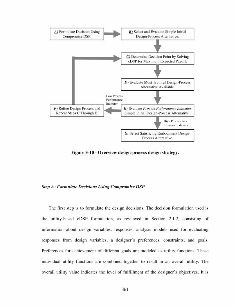
361
Figure 5-10 - Overview design-process design strategy.
Step A: Formulate Decisions Using Compromise DSP
The first step is to formulate the design decisions. The decision formulation used is
the utility-based cDSP formulation, as reviewed in Section 2.1.2, consisting of
information about design variables, responses, analysis models used for evaluating
responses from design variables, a designer’s preferences, constraints, and goals.
Preferences for achievement of different goals are modeled as utility functions. These
individual utility functions are combined together to result in an overall utility. The
overall utility value indicates the level of fulfillment of the designer’s objectives. It is
B) Select and Evaluate Simple Initial
Design-Process Alternative.
D) Evaluate Most Truthful Design-Process
Alternative Available.
G: Select Satisficing Embodiment Design-
Process Alternative.
A) Formulate Decision Using
Compromise DSP.
C) Determine Decision Point by Solving
cDSP for Maximum Expected Payoff.
High Process Per-
formance Indicator
Low Process
Performance
Indicator
E) Evaluate Process Performance Indicator
Simple Initial Design-Process Alternative .
F) Refine Design-Process and
Repeat Steps C Through E.
362
important to note that changing the utility function will have an effect on the specific
decisions (values of design variables and Process Performance Indicators) made using the
method. However, it does not affect the steps followed in the method. Even by changing
the shape of the preferences, the conclusions about the applicability of the method and
the metric remain the same.
Step B: Select Least Complex Initial Design-Process Alternative
In the second step, a least complex but valid initial design-process alternative is
selected. In this step, ensuring model validity, i.e., predicting trends correctly, is crucial,
as reviewed in Section 5.2.3. Based on the results of the following steps, a designer
decides whether to use the information produced by the least complex but valid initial
design-process alternative or perhaps refine the design-process.
Step C: Determine Decision Point
In Step C, the selected least complex initial design-process alternative is evaluated
based on the weighted objective function given in the utility based cDSP formulation.
The point in the design space that minimizes the objective function, called the decision
point (dp), is determined. Depending on a designer’s preferences, the decision point may
363
be located at a local (global) minimum (maximum) or flat region, particularly in the
context of robust design, in the design space.
With respect to evaluating the performance of the least complex initial design-process
alternative, at least a +/- 5 % sensitivity in the main effect should be analyzed. However,
acquiring more information to analyze sensitivity is beneficial, but, depends on the
computational efficiency of the most truthful design-process alternative. The information
obtained is used to evaluate the most truthful design-process alternative in the following
section.
Step D: Select and Evaluate Most Truthful Design-Process Alternative
In Step D, the most truthful design-process alternative is selected and evaluated. It
serves as a baseline for determining the Process Performance Indicator locally at the
specific decision points where expected maximum payoff occurs as identified in Step C.
Again, ensuring model validity is crucial, as reviewed in Section 5.2.3.
Step E: Evaluate Process Performance Indicator Least Complex Initial Design-Process
Alternative
Having evaluated both the least complex initial and most truthful design-process
alternative at the identified decision points, the Process Performance Indicator is
364
evaluated. If the Process Performance Indicator is evaluated at multiple points, a
sampling guideline, as summarized in Table 5-4, and an evaluation scenario, as identified
for example in Equations 4 through 6, are selected. In most cases, a conservative
evaluation scenario of using the minimum value of the values determined at different
decision points is recommended. This however, depends on the decision maker’s mindset
and given design problem context. However, having determined an overall Process
Performance Indicator, its value is to be evaluated to decide whether or not the decision
maker considers the current design-process alternative satisficing or prefers to refine the
design-process alternative by refining the design-process. If the decision maker decides to
refine the design-process alternative, Step F follows; otherwise Step G.
Step F: Refine Design-Process and Repeat Steps C Through E
If the decision maker decides to refine the design-process alternative based on the
Process Performance Indicator value, Steps C through E are to be repeated. Step F may
be repeated until a satsificing design-process alternative, most likely with a Process
Performance Indicator of close to the maximum possible value of 1, is obtained.
However, it is emphasized that evaluation of the Process Performance Indicator is based
on the assumptions that analysis models are valid, i.e., predict trends correctly. If that
assumption is violated Process Performance Indicator values are certainly not in line with
system behavior.
365
Step G: Select Satisficing Embodiment Design-Process Alternative
Results of the design-process alternatives generated and evaluated in terms of their
Process Performance Indicator are used to select a satisficing embodiment design-process
alternative. Selection thus involves making the trade-off between gathering more
information to refine performance predictions, in other words develop more refined
design-process alternatives, or using the design-process alternative developed for
decision making. If from a decision-centric perspective there is a very low chance
additional information gathering, in other words further refining the design-process, at
increased computational and modeling expense will have a great impact on the design
decision at the Process Performance Indicator value obtained, the specific design-process
alternative is selected.
366
5.5 Limitations and Opportunities for Future Work
Most of the “value-of-information” metrics are used to model the benefit achieved by
additional information only. The cost of gathering that information is not accounted for.
Similarly, the approach developed in this work is based on the premise that the
appropriateness of a design-process depends on the impact on a designer’s decisions. In
this work, the goal is to support a designer in making a satisficing decision using the most
appropriate design-process alternative.
A limitation of the value-of-information-based metric is that it only accounts for the
information about the improvement in payoff of the decision. It does not include the cost
of executing a more complex network of decisions and models and the time savings
through simplification are not included in this dissertation. It is assumed that for a given
step in the series of refinement steps, a designer evaluates the estimated cost of gathering
information and the value of this added information. Using these two indicators, a
designer makes the decision on whether additional information is worth gaining. Thus,
strictly speaking there is a trade-off between the value-of-information-based metric and
the cost (of refining an analysis model and executing the refined model). The scope of the
value-of-information-based metric is limited to the benefits achieved by specific design-
process alternatives in terms of the overall utility. However, this does not require a
change in the way the metric is applied. The only change that is required is to include
cost utility functions in the calculation of the overall utility in order to transform the
current “gross” value-of-information metric, only quantifying how much better/worse a
design decision is, into a “net” value-of-information metric.
367
The main advantage of the metric is that it is least complex to evaluate and quantifies
the impact of meta design decisions on product and material level decisions. But, the
metric can only be used to determine whether a certain design-process alternative is
appropriate for making a particular decision or not. Hence, based on the metric, a
designer cannot directly determine how the design-process should be refined. Also, it is
evaluated after computations have been made, i.e., after design-processes have been
instantiated. It only provides information about whether the current design-process needs
to be refined or not. Thus, the opportunity for improving the design-process by adding
more information is quantified.
Further investigation needs to be carried out for different types of refinement of
design-processes. For example, each design-process can be refined in various directions:
by considering additional physical phenomena, adding more parameters, coupling
physical phenomena, developing better analysis models of physical phenomena, etc. The
characterization of models should be able to isolate the effect of different types of
refinement. This is important in order to make decisions such as along which dimension
should the analysis model be refined. Currently, the combined effect of refinement is
calculated. If different types of characterization of information are available, better
metrics for design-processes are possible.
With respect to evaluating the Process Performance Indicator locally, future work
might involve developing advanced strategies to determine at which points in the design
space it is evaluated. Various guidelines are presented in this work, but, additional
approaches should be explored. Confidence in the Process Performance Indicator
increases with the number of points evaluated in the design space. However, if the most
368
truthful design-process alternative has been evaluated at a sufficient number of points in
the design space, a sufficiently accurate response surface can be generated. Then, this
response surface may be used for design space exploration. Since in the context of
integrated product and materials design the most truthful design-process alternative
usually incorporates very expensive to execute computer or physical analyses,
instantiating this design-process alternative at a sufficient number of points to generate a
sufficiently accurate response surface is not practically feasible since fidelity is sacrificed
for computational efficiency.
The advantage of the systematic strategy to design-process generation and selection is
that designers do not need to use the most complex design-process for decision making.
However, more than one refinement step may be required for determining the right level
of design-process refinement. In the worst case, multiple executions of design processes
at increasing levels of refinement may result in significant computational expenses. If this
exceeds the total cost of evaluating the most truthful design-process alternative, this is a
limitation. Hence, there is a tradeoff that calls forth a designer’s judgment based on the
expected benefits from stepwise refinement.
Stepwise refinement results in a cumulation of results for various design process
alternatives. Due to this cumulative nature of the design-process design strategy shown in
Figure 5-10, the number of points at which the Process Performance Indicator is
evaluated should be limited as much as feasible for the problem at hand. Also, the
strategy for design-process generation and selection is only one among many strategies a
designer may choose. However, it has shown to advantageous to use the strategy
369
proposed in this work especially in the context of integrated product and materials design.
Also, it can be used to consider any type of uncertainty reviewed in Section 2.4.3.
The value-of-information-based metrics developed so far can be improved further to
be used in more complex design scenarios. Value-of-information-based design-process
simplification or refinement has so far been only addressed for networks of a maximum
of two analysis models and two decisions. Systematic approaches need to be extended to
networks of decisions and analysis models involving a) more than two decisions and
analysis models, and b) hierarchical multilevel decisions and simulation models. Hence,
the question research in this area should address is: “How can a general design procedure
be developed for systematically managing complexity and generating robust design
specifications at multiple levels in the context of complex engineered systems?”.
5.6 On Verification and Validation – Theoretical Structural Validation
In this chapter, theoretical structural validation as one aspect of the validation square
is addressed. An overview of the validation performed in this dissertation is presented in
Section 1.3. Specific details related to validating the value-of-information-based design-
process design strategy presented in this Chapter are illustrated in Figure 3-10.
Theoretical structural validation refers to accepting the validity of individual
constructs used in the systematic approach and accepting the internal consistency of the
way the constructs are put together. Theoretical structural validation is carried out in this

370
chapter using a systematic procedure consisting of a) identifying the method’s scope of
application, b) reviewing the relevant literature and identifying the strengths and
limitations of the constructs in the literature, and c) identifying the gaps in existing
literature, and d) determining which constructs are leveraged in the systematic approach
while exploring the advantages, disadvantages, and accepted domain of application. The
internal consistency of the individual constructs is checked by a critical review of the
literature.
Concerning the value-of-information-based Process Performance Indicator, it has
been argued why value of information is appropriate as a metric for evaluating the
performance of design-processes, i.e., whether a designer need to determine additional
information. Based on the existing literature, it is shown that value of information has
been previously used for making similar decisions on addition of information for decision
making. The value-of-information-based index developed in this work is an indirect
index, i.e., an index related to direct metrics such as cost and time but more suitable to
the early design phases characterized by more or less incomplete, varying and mostly
qualitative information. Nevertheless, the general value-of-information concept has been
shown to provide a consistent framework from which performance metrics of design-
process alternatives can be quantified.
From the critical review of the literature, it is identified that the current metrics for the
value of information are not sufficient for many scenarios in integrated product and
materials design. This is primarily due to the assumption that knowledge of a truthful
design-process or its error bounds (either deterministic or probabilistic) throughout the
whole design space is available. Also, existing metrics deal with design-process
371
simplification and refinement either a) through simplifying and refining interactions or b)
through simplifying and refining analysis models in a complex network of decisions and
analysis models. Furthermore, the assumption of existing approaches is that designers
have the knowledge of a complete network of decisions and analysis models, which is
first simplified and then sequentially refined again. Hence, a new value-of-information-
based metric, the Process Performance Indicator, is developed in Section 5.3 to deal with
strategically refining interactions as well as analysis models starting with the least
complex but valid design-process alternative, while not being dependent on the
knowledge of a truthful design-process or its error bounds (either deterministic or
probabilistic) throughout the whole design space – crucial for many scenarios in
integrated product and materials design.
Due to the logical procedure of literature review, gap analysis, as well as
development and evaluation of a new metric, the theoretical structural validity of the
individual constructs is accepted. Accepting internal consistency of the way constructs
are put together is investigated in Chapter 6.
5.7 Role of Chapter 5 in This Dissertation
In this chapter, focus has been on developing a value-of-information-based Process
Performance Indicator for assessing the performance of design-process alternatives, and a
strategy to design-process design based on the Process Performance Indicator for
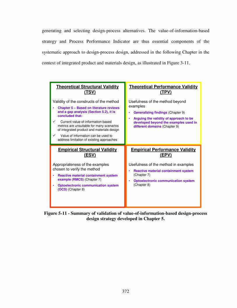
372
generating and selecting design-process alternatives. The value-of-information-based
strategy and Process Performance Indicator are thus essential components of the
systematic approach to design-process design, addressed in the following Chapter in the
context of integrated product and materials design, as illustrated in Figure 3-11.
Empirical Structural Validity (ESV)
Appropriateness of the exampleschosen to verify the method
• Reactive material containment system example (RMCS) (Chapter 7)
• Optoelectronic communication system (OCS) (Chapter 8)
Theoretical Performance Validity (TPV)
Usefulness of the method beyondexamples
• Generalizing findings (Chapter 9)
• Arguing the validity of approach to be developed beyond the examples used in different domains (Chapter 9)
Theoretical Structural Validity (TSV)
Validity of the constructs of the method
• Chapter 5 – Based on literature reviews and a gap analysis (Section 5.2), it is concluded that:
� Current value-of-information-based
metrics are unsuitable for many scenarios of integrated product and materials design
� Value of information can be used to address limitation of existing approaches
Empirical Performance Validity (EPV)
Usefulness of the method in examples
• Reactive material containment system (Chapter 7)
• Optoelectronic communication system (Chapter 8)
Figure 5-11 - Summary of validation of value-of-information-based design-process
design strategy developed in Chapter 5.
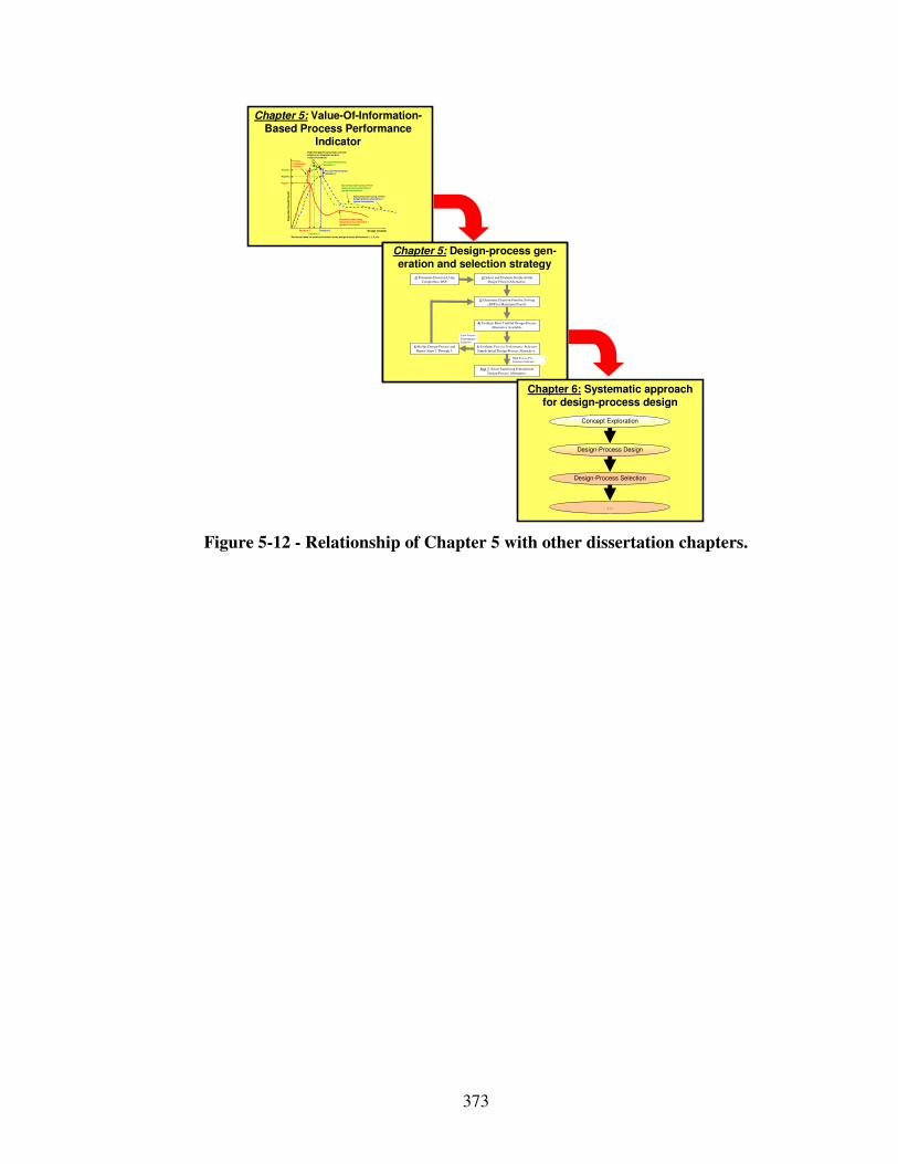
373
Chapter 5: Value-Of-Information-Based Process Performance
Indicator
Design Variable
Exp
ecte
d O
vera
ll P
ayo
ff
Expected payoff usingdesign process alternative 1(global information)
Expected payoff using refined design process alternative 2(global information)
Payoff 2
Decision 1 Decision 2
Payoff 1
Process Performance Indicator 1
Expected payoff using most accurate physical or simulation models(local information)
Process Performance Indicator 2
Decisions based on predicted behavior using design process alternatives 1, 2, 3, etc.
Process Performance Indicator 3
Expected payoff using refined design process alternative 3(global information)
Payoff 3
Decision 3
Chapter 5: Design-process gen-eration and selection strategy
Chapter 5: Design-process gen-eration and selection strategy
2) Select and Evaluate Simple Initial Design Process Alternative.
4) Evaluate Most Truthful Design-Process
Alternative Available.
Step 7: Select Satisficing Embodiment
Design-Process Alternative.
1) Formulate Decision Using Compromise DSP.
3) Determine Decision Point by Solving
cDSP for Maximum Payoff.
High Process Per-
formance Indicator
Low Process
Performance Indicator
5) Evaluate Process Performance Indicator
Simple Initial Design-Process Alternative .
6) Refine Design-Process and
Repeat Steps 3 Through 5.
Chapter 6: Systematic approach for design-process design
Design-Process Design
…
Design-Process Selection
Concept Exploration
Figure 5-12 - Relationship of Chapter 5 with other dissertation chapters.
374
Chapter 6 Synthesizing the Systematic Approach to Integrated Design of Products, Materials, and Design-
Processes
Having developed the i) function-based systematic approach to the integrated design
of product and material concepts including design catalogs in Chapters 3 and 4 as well as
ii) the value-of-information based Process Performance Indicator and strategy to
embodiment design-process generation and selection in Chapter 5, these constructs are
synthesized to the systematic approach to integrated product, materials, and design-
process design in this chapter. Describing its applicability for both original and adaptive
design, verification and validation of the systematic approach and its constructs are
discussed.
6.1 Context – Answering the Primary Research Question
In this chapter, all requirements for the systematic approach as listed in Table 1-6 are
addressed. Hence, the systematic approach is synthesized in this chapter to address the
primary research hypothesis as highlighted in Figure 6-1. The reactive material
containment system example is used in Chapter 7 to test all aspects of the systematic
approach; the optoelectronic communication system example is used in Chapter 8 to test
the design-process generation and selection as well as the value-of-information based
Process Performance Indicator developed for answering Research Question 2.

375
Systematic design-process generation and selection
strategy
Value-Of-Information-Based Process Performance Indicator
Systematic approach for integrated product, materials,
and design-process design
Design catalogs phenomena and associated solution principles
Systematic, function-based approach for integrated,
conceptual design
Systematic mapping of classified phenomena and
solution principles from multiple scales and
disciplines to multilevel function structures
Creating multilevel function structures based on
functional analysis, abstraction and synthesis
Ex,in
M x,in
Ex,in
System boundary
System function x Exyz,out
System function z
System function y
Ey,in
Sz,i n
M x,in Sub-system function xx
Ex,out
Sub-system function xy
Sz,in
Ey,in Material function yx
Eyz,out
Material function zx
Sub-system boundarySystem level
Sub-system level
Material level
Clarification of Task
Multilevel Function Structure Selection
Concept Selection
Concept
Principle
Phenomenon
Function
Pheno-menon
Scale Properties Applications
"Monolithic" materials
- Metals Compared to a ll other classes of material , metals are stif f, strong and tough, but
they are heavy. They have rel atively hi gh melti ng points. Only one metal - gold - is
chemically stable as a metal . Metals are d uctile, all owing them to be shaped by
roll ing, forgin g, drawi ngn and extrusion. They are easy to machine with precision, and they can be j oined i n many different ways. Iron an d nickel are transit ional
metals involving both metallic and covalent bonds, and tend to be less d uctile than
other meta ls. However, metals conduct electricity well , ref lect light a nd are
completely opaque. Pri mary producti on of metals is ene rgy i ntensive. Man y
require at least twice as much energy per un it weight than commodity polymers.
But, metals can general ly be recycl ed and the energy required to do so is much l ess than that requried for primary production. Some are toxi c, others are so inert
that they can be i mpl anted in the human body.
- Al uminum-, copper-,
magnesi um-, nickel-, steel -,
ti tanium-, zinc-al loys
- Carbon-, stainles-, … steels
- Amorphous meta ls, …
Ela
sti
c/in
ela
sti
c d
efo
rmat
ion
(te
ns
ion
, c
om
pre
ssi
on
, be
nd
ing
, sh
ear
, to
rsio
n,
bu
ckl
ing
, fr
actu
re, c
utt
ing
, in
ver
sio
n, e
xtr
usi
on
,
Characteristics
Solution Principle
- Pol ymers
From a macroscale, monolith ic materials are referred to as matter, i.e., the substance of which physi cal objects are composed.
Polymers feature an immense range of form, color, surface fini sh, transluce ncy, transparency, toughness a nd f lexibility. Ease of moldi ng all ows sh apes that i n
other mate ri als could only be bui lt up by expensive assembly methods. Their
excellent workabili ty all ows the mol ding of complex forms, al lowing cheap
manufacture of i ntegrated components that previously were made b y assembling
many parts. Many polymers are cheap both to b uy and shape. Most resist water,
acids and alkali s well, though organic so lvents attack some. All are light and ma ny are fl exibl e. Their properties change rapidly with temperature. Even at room
temperature many creep and when cooled the y may become brit tl e. Pol ymers
generall y are sensiti ve to UV radiation and to strongly oxidi zing environments.
- Thermosplastic p olymers: ABS, Cellulose, Ionomers,
Nyl on/PA, PC, PEEK, PE,
PMMA, POM, PP, PS, PTFE,
tpPVC, tpPU,
PET/PETE/PBT
- Thermosett ing pol ymers: Epoxy, Phenolic, Pol yester,
tsPU, tsPVC
- El astomers: Acrylic
machining.
Honeycomb-cor e
sandwiches
- In-plane honeycombs Core cel l axes of in-plane honeycomb cores are oriented paral lel to the face-
sheets. They provide potenti als for decreased conductivity and f luid f low within
cells. Relative densit ies range from 0.001 to 0.3. Their densif icatio n strain can be approximated as:
Their relat ive st iffness can be approximated as:
Their relat ive stren gth can be ap proximated as:
- Prismati c-, square-,
chiracal-, etc. core in-plane
honeycombs
- Out-o f-plane honeycombs Core cel l axes of out-of-pl ane honeycomb cores are oriented perpendicular to
face-sheets. They provide potentials for decreased conducti vi ty. Relative densities
range from 0.001 to 0.3. Their densif ication strain can be approxi mated as:
Their relat ive st iffness can be approximated as:
Their relat ive stren gth can be ap proximated as:
- Hexagonal-, sqau re-, etc.
core put-of-plane
honeycombs
Fiber-composite s
- Conti nuous fi ber
composites
Continuous f iber composites are composi tes wi th highest st if fness and strength.
They are made of continuous fibers usuall y embedd ed in a thermosetting resin. The f ibers carry the mechani cal loads whi le the matrix material transmits loads to
the f ibers and provides ducti lity an d toughness as well as protecting the fibers
from damage caused by h andling or the environmen t. I t is the matrix material that
l imi ts the service temperature and proce ssing conditio ns. On mesoscales, the
propert ies can be strongly i nfluenced by the choice of f iber and matrix and the
way i n which these are combined: f iber-resin ratio, fi ber length, fi ber orientation, l aminate thickness and the presence of fiber/resi n coupling agents to improve
bondi ng. The strength of a composite is increased by raising the f iber-resin ratio,
and orienting the f ibers parall el to the l aoding di rection. Increased lami nate
thickness leads to reduced composite strength and modulus as there is an
i ncreased likelihood of entrapped voids. Environmental conditi ons affect the
performance of composites: fat igue l oading, moisture and heat all
reduce allowable strength. Polyesters are the most most wi dely used matri ces as they offer reasonable propertie s at relati vely low cost. The superior propert ies of
epoxies and the termperature performance of polyi mide s can justify their use in
certa in appli cations, but they are expensive.
- Glass f ibers [high strength
at low cost], polymer f ibers (organic (e.g., Kevl ar) or
anorganic (e.g., Nylon,
Polyester)) [reasonable
properties at relatively l ow
cost], carbon fibe rs [very high
strength, st if fness and low density]
- Strands, fil aments, fibers,
yarns (twisted strands),
rovi ngs (bundled strands)
- Nonwoven matt ings,
weaves, braids, knits, other
- Disco ntinuous fiber
composites
Polymers rei nforced with chopped polymer, wood, glass o r carb on f ibers are
referre d to as di scontinuous f iber composites. The longer the fi ber, the more
eff ici ent is the reinforcement at carryi ng the appli ed loads, but shorter fi bers are easier to process an d hence cheaper. Hence, f iber length and material are the
governing design variables. However, fibrous core composites fea ture shape
f lexibili ty and relati vely high bendi ng sti ffness at low densi ty.
- Glass f ibers, polymer fibers
(organic (e.g., Kevl ar) or
anorganic (e.g., Nylon, Polyester)), carbon f ibers
Me
so
sc
ale
Ela
sti
c/i
ne
lasti
c d
efo
rm
ati
on
(te
nsio
n,
co
mp
ressio
n, b
en
din
g, s
he
ar,
to
rsio
n, b
uc
kli
ng
, fr
actu
re,
cu
ttin
g,
inv
ers
ion
, e
xtr
us
ion
, d
raw
ing
,
flo
w)
Honeycomb-core sandwiches take thei r name from their visu al resemblance to a bee's honeycomb. W ith controlla ble core di mensions
and topologies on mesoscale s, they freature relatively high stif fness and yield strength at low d ensi ty. Larg e compressive strai ns are achievable at nominal ly constant stress (before the material compa cts), yieldi ng a potentially hi gh energy absorpti on capacity. Honeycomb-
core sandwiches have acceptabl e structural performance a t rel atively low costs with useful combinations of thermophysical and
mechani cal properti es. Usually, they provide benefits with respect to mult iple use.
The combin ation of polymers or other ma trix materi als with f ibers has gi ven a range of light materi als with st iffness and strength
comparable to that of metals. Commonly, resin materi als are e poxi es, pol yesters and vinyls. Fibers are much stronger and stif fer than
thei r equivalent in bulk form because the drawing process by they are made orients the polymer ch ains along the fi ber axis or re duces the
density of defects.
−≈
s
D ρ
ρε 4.11
31 rel
sE
Eρ≈
relys
y ρσ
σ5.0≈
rel
sE
Eρ1≈
r el
ys
y ρσ
σ1≈
−≈
s
D ρ
ρε 4.11
Output
Input
Mechanical
Energy
(In)elastic de-
formation
Inertia
…
Electrostric-
tion…
Magnetostric-
tion…
Impact
…
Friction
…
Pressure
change…
Dislocation
hardening…
Electrostatic
Energy
Electric f ield
…
Interference
…
Hall-effect
…
Electrostric-
tion
…
Photostric-
tion
…
Electrical
resistance
…
Galvanic
element
…
Magnetostatic
Energy
Magnetic field
…
Oscillating
circuit
…
Ferromag-
netism
…
Magneto-
striction
…
Farraday-
effect
…
Eddy current
…
Sound
Energy
Pressure wave
…
Electrostric-
tion
…
Magnetostric-
tion
…
Reflection
…
Noise dam-
ping
…
Elasticity
…
Light
Energy
Electromag-
netic radiation
…
Photostric-tion
…
Absorption
…
Refraction
…
Thermolumi-
nescence
…
Photoeffect
…
Thermal
Energy
Thermal
expansion
…
Thermoelectri
city
…
Curie-Weiss
law
…
Pyro-
electricity
…
Convection
…
Phase trans-
formation
…
Molecular
Energy
Exothermic
reaction
…
Molecular
dipoloe
…
Fluores-
cence
…
Combustion
Conductivity
…
Adhesion
…
Light
Energy
Thermal
Energy
Molecular
Energy
Mechanical
Energy
Electrostatic
Energy
Magnetostatic
Energy
Sound
Energy
Design Variable
Ex
pe
cte
d O
vera
ll P
ayo
ff
Expected payoff using
design process alternative 1
(global information)
Expected payoff using refined
design process alternative 2(global information)
Payoff 2
Decision 1 Decision 2
Payoff 1
Process
Performance Indicator 1
Expected payoff using most accurate physical or simulation models
(local information)
Process Performance Indicator 2
Decisions based on predicted behavior using design process alternatives 1, 2, 3, etc.
Process Performance
Indicator 3
Expected payoff using refined design process alternative 3
(global information)
Payoff 3
Decision 3
Template-based decision-centric concept
exploration accounting for uncertainty and
complexity of multilevel and multiscale design
Evaluation of design-process alternatives and
value of additional multiscale modeling based on
Process Performance Indicator
Multilevel Function Structure Selection
Clarification of Task
Design-Process Design
Embodiment Design
Design-Process Selection
Concept Selection
Creating multilevel function structures based on
functional analysis, abstraction and synthesis
Systematic mapping of classified phenomena
and solution principles from multiple scales and
disciplines to multilevel function structures
System atic generation of multiscale design-
process alternatives based on a value-of-
information-based strategy
Evaluation of design-process alternatives and additional modeling potential
through a value-of-information-based Process Performance Indicator
Systematic generation of design-process alternatives based on
principles from information economics
Design-Process Evaluation
Design-Process Selection
Concept Exploration and Selection
Template-based decision-centric embodiment design
2) S elect and Evaluate Simple Initial
Design Process Alternative.
4) Evaluate most truthful design process
alternative available.
Step 7: Select satisficing embodiment
design process alt ernative.
1) Formulate Decision Using
Compromi se DSP.
3) Determine Decision Point by Solving
cDSP for Maximum Payoff.
High Process Per-formance Indicator
Low Process Performance Indicator
5) Evaluate Process Perf ormance Indi catorS imple Initial Design-Process Alternative .
6) Refine Design-Process and Repeat Steps 3 Through 5.
…
Primary Research Hypothesis: “… systematic approach towards integrated product, advanced multifunctional materials, and associated
embodiment design-process design is developed to increase a designer’s concept and design-process flexibility …”
Figure 6-1 - Construct of the systematic approach focused on and hypotheses
addressed in Chapter 6.
In this chapter and Section 6.2, focus has been on synthesizing the overall systematic
approach based on both components – the function-based systematic approach to the
integrated design of product and material concepts facilitated through the use of design
catalogs developed in Chapters 3 and 4, as well as the systematic approach to design-
process design from a decision-centric perspective developed in Chapter 5. An overview
of specific steps of the overall systematic approach and its components are described in
Section 6.2.1. Then, specific steps are described in greater detail in Section 6.2.2 through
6.2.6. In Section 6.3, suggestions of how to use the developed systematic approach for
adaptive are presented, referring the to the methods and tools for achieving product
flexibility reviewed in Section 2.4. In Section 6.4, theoretical structural validation of the
376
overall systematic is addressed and overview of its empirical structural and performance
validation is given. Finally, the role of Chapter 6 in this dissertation and relationships
with other dissertation chapters are presented in Section 6.5.
6.2 Overview Systematic Approach to the Integrated Design of Products, Materials, and Design-Processes
In this section, the overall systematic approach is synthesized and described. After
presenting the overall systematic approach and its components in Section 6.2.1, specific
steps are described in detail in Section 6.2.2 through 6.2.6.
6.2.1 Synthesizing the Systematic Approach to the Integrated Design of Products, Materials, and Design-Processes
The main contribution in this work is the development of a systematic approach
towards the integrated design of products, advanced multifunctional materials, and
associated embodiment design-processes from a systems perspective, i.e., based on a
holistic understanding of the scientific phenomena and principles at multiple levels and
scales.
In response to Research Question 1 –

377
“How can the design of product and material concepts be integrated, and conceptual
materials design be rendered more systematic and domain-independent to support a
designer’s concept flexibility?”
– a function-based systematic approach to the integrated design of product and material
concepts from a systems perspective facilitated through the use of design catalogs has
been developed in Chapters 3 and 4, as illustrated in Figure 6-2.
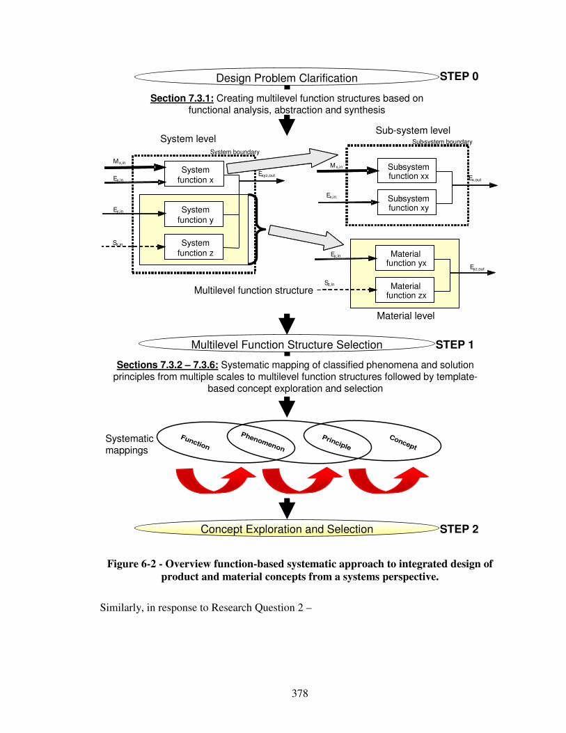
378
Sections 7.3.2 – 7.3.6: Systematic mapping of classified phenomena and solution principles from multiple scales to multilevel function structures followed by template-
based concept exploration and selection
Section 7.3.1: Creating multilevel function structures based on functional analysis, abstraction and synthesis
Ex,in
Mx,in
Ex,in
System boundary
System function x
Exyz,out
System function z
System
function y
Ey,in
Sz,in
Mx,in Sub-system function xx Ex,out
Sub-system function xy
Sz,in
Ey,in Material function yx
Eyz,out
Material function zx
Sub-system boundarySystem levelSub-system level
Material level
Design Problem Clarification
Multilevel Function Structure Selection
Concept Exploration and Selection
Concept
Principle
Phenomenon
Function
STEP 0
STEP 1
STEP 2
Systematic mappings
Multilevel function structure
Figure 6-2 - Overview function-based systematic approach to integrated design of
product and material concepts from a systems perspective.
Similarly, in response to Research Question 2 –
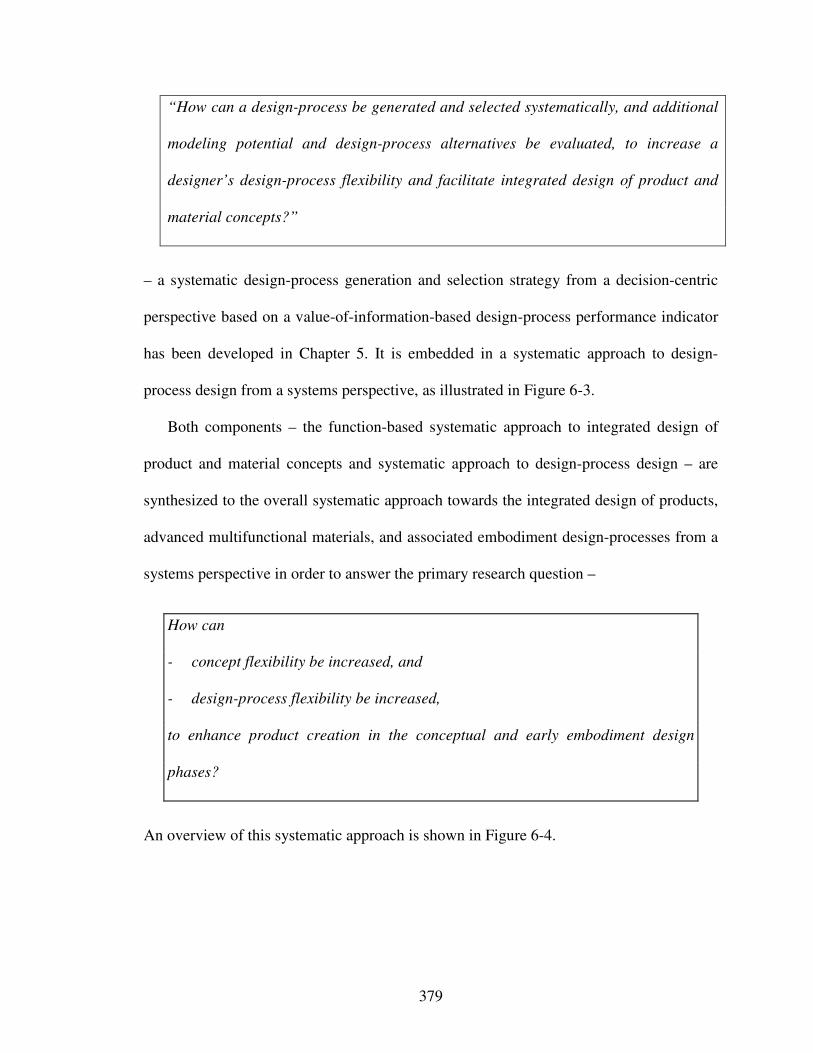
379
“How can a design-process be generated and selected systematically, and additional
modeling potential and design-process alternatives be evaluated, to increase a
designer’s design-process flexibility and facilitate integrated design of product and
material concepts?”
– a systematic design-process generation and selection strategy from a decision-centric
perspective based on a value-of-information-based design-process performance indicator
has been developed in Chapter 5. It is embedded in a systematic approach to design-
process design from a systems perspective, as illustrated in Figure 6-3.
Both components – the function-based systematic approach to integrated design of
product and material concepts and systematic approach to design-process design – are
synthesized to the overall systematic approach towards the integrated design of products,
advanced multifunctional materials, and associated embodiment design-processes from a
systems perspective in order to answer the primary research question –
How can
- concept flexibility be increased, and
- design-process flexibility be increased,
to enhance product creation in the conceptual and early embodiment design
phases?
An overview of this systematic approach is shown in Figure 6-4.
380
Evaluation of design-process alternatives and additional modeling potential through a value-of-information-based Process Performance Indicator
Systematic generation of design-process alternatives from a decision-centric perspective
Design-Process Evaluation
Design-Process Selection
Concept Exploration and Selection
Template-based decision-centric embodiment design
Design Variable
Exp
ecte
d O
vera
ll P
ayo
ff
Expected payoff usingdesign process alternative 1(global information)
Expected payoff using refined design process alternative 2(global information)
Payoff 2
Decision 1 Decision 2
Payoff 1
Process Performance Indicator 1
Expected payoff using most accurate physical or simulation models(local information)
Process Performance Indicator 2
Decisions based on predicted behavior using design process alternatives 1, 2, 3, etc.
Process Performance Indicator 3
Expected payoff using refined design process alternative 3(global information)
Payoff 3
Decision 3
…
Go als
P referenc es
Vari abl es
Pa ra meters
Con strain ts
Re spo nse
Obj ect i ve
Fully Instantia ted cDSPTemplate
D ri ver
A nal ysi s
Go als
P referenc es
Vari abl es
Pa ra meters
Con strain ts
Re spo nse
Obj ect i ve
Fully Instantia ted cDSPTemplate
D ri ver
A nal ysi s
P1 P2 P3
P6
P9P8P7
P4 P5
Validation
X1 Y1
X2 Y2
X1 Y1
X2 Y2
X1
Y1
X2 Y2
Analysis i
Go als
P referenc es
Vari abl es
Pa ra meters
Con strain ts
Re spo nse
Obj ect i ve
F ul l y In s tan t i a ted c D S P T e mp l a te
D ri ver
A nal ysi s
Go als
P referenc es
Vari abl es
Pa ra meters
Con strain ts
Re spo nse
Obj ect i ve
F ul l y In s tan t i a ted c D S P T e mp l a te
D ri ver
A nal ysi s
Analysis i
Go als
P referenc es
Vari abl es
Pa ra meters
Con strain ts
Re spo nse
Obj ect i ve
F ul l y In s tan t i a ted c D S P T e mp l a te
D ri ver
A nal ysi s
Analysis i
Go al s
Preferen ces
Va ri ab le s
P arameters
Co nstrai nts
Res pon se
Ob je ct ive
Fully Instantiated cDSP Template
Dri ver
An aly si s
X1 Y1 X1 Y1 X1 Y1
Go als
P referenc es
Vari abl es
Pa ra meters
Con strain ts
Re spo nse
Obj ect i ve
Fully Instantia ted cDSPTemplate
D ri ver
A nal ysi s Go als
P referenc es
Vari abl es
Pa ra meters
Con strain ts
Re spo nse
Obj ect i ve
Fully Instantia ted cDSPTemplate
D ri ver
A nal ysi s
Go als
P referenc es
Vari abl es
Pa ra meters
Con strain ts
Re spo nse
Obj ect i ve
Fully Instantia ted cDSPTemplate
D ri ver
A nal ysi s
Go als
P referenc es
Vari abl es
Pa ra meters
Con strain ts
Re spo nse
Obj ect i ve
Fully Instantia ted cDSPTemplate
D ri ver
A nal ysi s
Go als
P referenc es
Vari abl es
Pa ra meters
Con strain ts
Re spo nse
Obj ect i ve
Fully Instantia ted cDSPTemplate
D ri ver
A nal ysi s
X1 Y1
X2 Y2
X1 Y1
X2 Y2
X1
Y1
X2 Y2
Go al s
Preferen ces
Va ri ab le s
P arameters
Co nstrai nts
Res pon se
Ob je ct ive
Fully Instantiated cDSP Template
Dri ver
An aly si s
Go als
P referenc es
Vari abl es
Pa ra meters
Con strain ts
Re spo nse
Obj ect i ve
Fully Instantia ted cDSPTemplate
D ri ver
A nal ysi s Go als
P referenc es
Vari abl es
Pa ra meters
Con strain ts
Re spo nse
Obj ect i ve
Fully Instantia ted cDSPTemplate
D ri ver
A nal ysi s
Go als
P referenc es
Vari abl es
Pa ra meters
Con strain ts
Re spo nse
Obj ect i ve
Fully Instantia ted cDSPTemplate
D ri ver
A nal ysi s
Go als
P referenc es
Vari abl es
Pa ra meters
Con strain ts
Re spo nse
Obj ect i ve
Fully Instantia ted cDSPTemplate
D ri ver
A nal ysi s
Go als
P referenc es
Vari abl es
Pa ra meters
Con strain ts
Re spo nse
Obj ect i ve
Fully Instantia ted cDSPTemplate
D ri ver
A nal ysi s
Go al s
Preferen ces
Va ri ab le s
P arameters
Co nstrai nts
Res pon se
Ob je ct ive
Fully Instantiated cDSP Template
Dri ver
An aly si s
Go al s
Preferen ces
Va ri ab le s
P arameters
Co nstrai nts
Res pon se
Ob je ct ive
Fully Instantiated cDSP Template
Dri ver
An aly si s
Go als
P referenc es
Vari abl es
Pa ra meters
Con strain ts
Re spo nse
Obj ect i ve
Fully Instantia ted cDSPTemplate
D ri ver
A nal ysi s
Go als
P referenc es
Vari abl es
Pa ra meters
Con strain ts
Re spo nse
Obj ect i ve
Fully Instantia ted cDSPTemplate
D ri ver
A nal ysi s
Go als
P referenc es
Vari abl es
Pa ra meters
Con strain ts
Re spo nse
Obj ect i ve
Fully Instantia ted cDSPTemplate
D ri ver
A nal ysi s
Go als
P referenc es
Vari abl es
Pa ra meters
Con strain ts
Re spo nse
Obj ect i ve
Fully Instantia ted cDSPTemplate
D ri ver
A nal ysi s
Go als
P referenc es
Vari abl es
Pa ra meters
Con strain ts
Re spo nse
Obj ect i ve
Fully Instantia ted cDSPTemplate
D ri ver
A nal ysi s Go als
P referenc es
Vari abl es
Pa ra meters
Con strain ts
Re spo nse
Obj ect i ve
Fully Instantia ted cDSPTemplate
D ri ver
A nal ysi s
Go als
P referenc es
Vari abl es
Pa ra meters
Con strain ts
Re spo nse
Obj ect i ve
Fully Instantia ted cDSPTemplate
D ri ver
A nal ysi s
Go als
P referenc es
Vari abl es
Pa ra meters
Con strain ts
Re spo nse
Obj ect i ve
Fully Instantia ted cDSPTemplate
D ri ver
A nal ysi s
STEP 3
STEP 2
STEP 4
B) Select and Evaluate Simple Initial
Design-Process Alternative.
D) Evaluate Most Truthful Design-Process
Alternative Available.
G: Select Satisficing Embodiment Design-
Process Alternative.
A) Formulate Decision Using
Compromise DSP.
C) Determine Decision Point by Solving
cDSP for Maximum Expected Payoff.
High Process Per-
formance Indicator
Low Process
Performance
Indicator
E) Evaluate Process Performance Indicator
Simple Initial Design-Process Alternative .
F) Refine Design-Process and
Repeat Steps C Through E.
Goals
Preferences
Variables
Parameters
Constraints
Response
Objective
Analysis 1
Fully Instantiated cDSP Template
Driver
Analysis 2
Analysis i
Figure 6-3 - Overview systematic approach to design-process design from a systems
perspective.

381
Template-based decision-centric embodiment
design
Evaluation of design-process alternatives and additional modeling potential through a value-of-
information-based Process Performance Indicator
Multilevel Function Structure Selection
Design Problem Clarification
Design-Process Evaluation
Design-Process Selection
Concept Exploration and Selection
Co
nc
ep
tual
Desig
n
-R
esea
rch
Qu
es
tio
n 1
- Creating multilevel function structures based on functional analysis, abstraction and synthesis
Systematic mapping of classified phenomena and
solution principles from multiple scales to multilevel function structures followed by template-based
concept exploration and selection
Desig
n-P
roce
ss D
esig
n a
nd
Co
ncep
t E
xp
lora
tio
n
-R
es
earc
h Q
ues
tio
n 2
-
STEP 0
STEP 3
STEP 1
STEP 4
STEP 2
…
Systematic generation of design-process alternatives based from a decision-centric
perspective
Output
Input
Mechanical
Energy… … … … … … …
Electrostatic
Energy… … … … … …
Magnetostatic
Energy… … … … … …
Sound
Energy… … … … … …
Light
Energy… … … … … …
Thermal
Energy… … … … … …
Molecular
Energy… … … … … …
Light
Energy
Thermal
Energy
Molecular
Energy
Mechanical
Energy
Electrostatic
Energy
Magnetostatic
Energy
Sound
Energy
Advanced multifunctional material
Ex,in
Mx,in
Ex,in
System boundary
System function x Exyz,out
System function z
System function y
Ey,in
Sz,in
Mx, in Sub-system function xx
Ex,out
Sub-system function xy
Sz, in
Ey, in Material function yx
Eyz,out
Material function zx
Sub-system boundarySystem level
Sub-system level
Material level
Design Variable
Ex
pe
cte
d O
vera
ll P
ayo
ff
Expected payoff usingdesign process alternative 1(global information)
Expected payoff using refined design process alternative 2(global information)
Payoff 2
Decision 1 Decision 2
Payoff 1
Process Performance Indicator 1
Expected payoff using most accurate physical or simulation models(local information)
Process Performance Indicator 2
Decisions based on predicted behavior using design process alternatives 1, 2, 3, etc.
Process Performance Indicator 3
Expected payoff using refined design process alternative 3(global information)
Payoff 3
Decision 3
Goals
Preferences
Variables
Parameters
Constraints
Response
Objective
Analysis
Driver
Instantiated cDSP Template
Driver
BRP analysis model
Response
core
front
backσ σ
εε
Blast
A
t
Other constraints, variables, parameters, goals, and preferences
Material properties
Objective function
Pheno-menon
S cale Properties Applications
"Monolithic" materials
- Metals Compared to all other classes of material, metals are stiff, str ong and tough, but
they are heavy. They have relatively high melting points. Only one metal - gold - is chemically stable as a metal. Metals are ductile, allowing them to be shaped by rolling, forging, drawingn and extrusion. They are easy to machine with precision, and they can be joined in many different ways. Iron and nickel are transitional
metals involving both metallic and covalent bonds, and tend to be less ductile than other metals. However, metals conduct electricity well, reflect light and are completely opaque. Pr imary production of metals is ener gy intensive. Many requir e at least tw ice as much ener gy per unit w eight than commodity polymers.
But, metals can generally be recycled and the energy required to do so is much less than that requried for primary production. S ome are toxic, others are so inert that they can be implanted in the human body.
- Aluminum- , copper-,
magnesium-, nickel-, steel-, titanium-, zinc-alloys - C arbon-, stainles-, … steels
- Amorphous metals, …
Ela
stic
/inel
as
tic
de
form
ati
on
(te
ns
ion
, co
mp
res
sio
n,
be
nd
ing
, s
he
ar,
tors
ion
, b
uc
kli
ng
, fr
ac
ture
, c
utt
ing
, in
ve
rsio
n,
ex
tru
sio
n,
Characteristics
Solution Principle
- P olymers
From a macroscale, monolithic materials are referred to as matter , i.e., the substance of which physical objects are composed.
Polymers feature an immense range of for m, color, surface finish, tr anslucency, transparency, toughness and flexibility. Ease of molding allows shapes that in
other materials could only be built up by expensive assembly methods. Their excellent w orkability allow s the molding of complex forms, allowing cheap manufacture of integrated components that previously were made by assembling many parts. Many polymers are cheap both to buy and shape. Most resist w ater,
acids and alkalis well, though organic solvents attack some. All are light and many are flexible. Their properties change rapidly with temperature. Even at r oom temper ature many creep and when cooled they may become brittle. Polymer s gener ally ar e sensitive to U V radiation and to strongly oxidizing environments.
- Thermosplastic polymers: AB S, Cellulose, Ionomers,
N ylon/PA, PC , PEEK , P E, PMMA, POM, PP, PS , PTFE, tpPVC , tpPU, PE T/PETE /PBT
- Thermosetting polymers: Epoxy, P henolic, Polyester, tsPU , tsPV C - Elastomer s: Acrylic
machining.
H oneycomb-core
sandwiches
- In-plane honeycombs Core cell axes of in-plane honeycomb cores are oriented parallel to the face-
sheets. They provide potentials for decreased conductivity and fluid flow within cells. Relative densities range from 0.001 to 0.3. Their densification str ain can be approximated as:
Their relative stiffness can be approximated as:
Their relative strength can be appr oximated as:
- Pr ismatic-, square-,
chir acal-, etc. core in- plane honeycombs
- Out-of-plane honeycombs Core cell axes of out-of-plane honeycomb cores are oriented perpendicular to face- sheets. T hey provide potentials for decreased conductivity. Relative densities
range from 0.001 to 0.3. Their densification strain can be approximated as:
Their relative stiffness can be approximated as:
Their relative strength can be appr oximated as:
- H exagonal- , sqaure-, etc. core put- of- plane
honeycombs
Fib er -composites
- C ontinuous fiber composites
Continuous fiber composites are composites with highest stiffness and str ength. They are made of continuous fiber s usually embedded in a thermosetting r esin. The fibers carry the mechanical loads w hile the matrix mater ial transmits loads to the fibers and pr ovides ductility and toughness as well as protecting the fibers
from damage caused by handling or the environment. It is the matrix material that limits the service temperatur e and processing conditions. On mesoscales, the properties can be strongly influenced by the choice of fiber and matrix and the
way in w hich these are combined: fiber-r esin ratio, fiber length, fiber orientation, laminate thickness and the presence of fiber /r esin coupling agents to improve bonding. The str ength of a composite is increased by raising the fiber-resin ratio, and or ienting the fibers parallel to the laoding direction. Increased laminate
thickness leads to reduced composite strength and modulus as there is an increased likelihood of entrapped voids. E nvironmental conditions affect the performance of composites: fatigue loading, moisture and heat all reduce allowable strength. P olyesters are the most most w idely used matrices as
they offer reasonable proper ties at relatively low cost. The superior proper ties of epoxies and the termper ature performance of polyimides can justify their use in certain applications, but they are expensive.
- Glass fibers [high strength at low cost], polymer fiber s (organic ( e.g., Kevlar ) or anorganic (e.g., Nylon,
Polyester)) [r easonable properties at relatively low cost], carbon fibers [very high
strength, stiffness and low density] - Str ands, filaments, fibers, yarns (tw isted strands),
rovings (bundled strands) - N onw oven mattings, w eaves, br aids, knits, other
- D iscontinuous fiber composites
Polymers reinforced w ith chopped polymer, wood, glass or carbon fiber s are referred to as discontinuous fiber composites. The longer the fiber, the more efficient is the reinforcement at carrying the applied loads, but shorter fibers are
easier to process and hence cheaper. Hence, fiber length and material are the governing design variables. H ow ever, fibrous core composites feature shape flexibility and relatively high bending stiffness at low density.
- Glass fibers, polymer fibers (organic ( e.g., Kevlar ) or anorganic (e.g., Nylon,
Polyester)), carbon fibers
Mes
os
cale
Ela
stic/ine
lastic d
efo
rm
atio
n (ten
sio
n, c
om
pre
ssion, b
endin
g, sh
ear, to
rsio
n, b
ucklin
g, fra
cture
, cutt
ing, inversio
n, extr
usio
n, draw
ing
,
flow
)
Honeycomb-core sandwiches take their name from their visual resemblance to a bee's honeycomb. With controllable core dimensions and topologies on mesoscales, they freature relatively high stiffness and yield strength at low density. Large compressive strains are achievable at nominally constant stress (befor e the material compacts), yielding a potentially high energy absorption capacity. H oneycomb-
core sandwiches have acceptable structural performance at relatively low costs w ith useful combinations of thermophysical and mechanical properties. Usually, they provide benefits with respect to multiple use.
The combination of polymer s or other matrix materials with fiber s has given a r ange of light materials with stiffness and str ength
comparable to that of metals. Commonly, resin materials are epoxies, polyesters and vinyls. Fibers are much stronger and stiffer than their equivalent in bulk form because the dr awing process by they are made orients the polymer chains along the fiber axis or reduces the density of defects.
−≈
s
D ρ
ρε 4.11
31 re l
sE
E ρ≈
rel
ys
y ρσ
σ5.0≈
rel
sE
E ρ1≈
rel
ys
yρ
σ
σ1≈
−≈
s
D ρ
ρε 4.11
2) Select and Evaluate Simple Initial
Design Process Alternative.
4) Evaluate most truthful design process
alternative available.
Step 7: Select satisficing embodiment
design process alternative.
1) Formulate Decision Using
Compromise DSP.
3) Determine Decision Point by Solving
cDSP for Maximum Payoff.
High Process Per-
formance Indicator
Low Process
Performance Indicator
5) Evaluate Process Performance Indicator
Simple Initial Design-Process Alternative .
6) Refine Design-Process and
Repeat Steps 3 Through 5.
Goals
PreferencesPreferences
Variables
Parameters
Constraints
Response
ObjectiveObjective
Analysis
DriverDriver
Partially Instantiated cDSP Template
Att
rib
ute
2
Attribute 1
Concept 2
Concept 5
Concept 1 Concept 3
Concept 6
Concept 4Concept
Principle
Phenomenon
Function
Figure 6-4 - Overview systematic approach to the integrated design of products,
materials and design-processes from a systems perspective.
The systematic approach consists of the following steps:
• Step 0 – Design Problem Clarification,
• Step 1 – Multilevel Function Structure Selection,
• Step 2 – Concept Exploration and Selection,
• Step 3 – Design-Process Evaluation, and
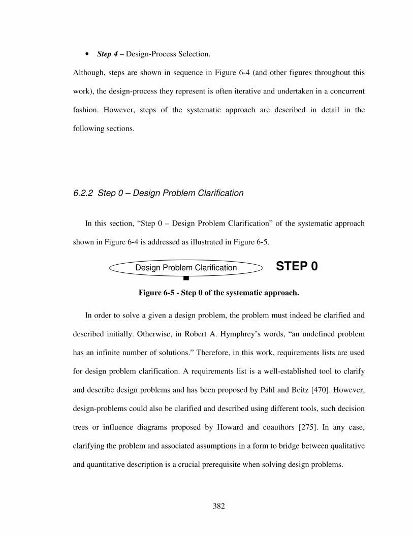
382
• Step 4 – Design-Process Selection.
Although, steps are shown in sequence in Figure 6-4 (and other figures throughout this
work), the design-process they represent is often iterative and undertaken in a concurrent
fashion. However, steps of the systematic approach are described in detail in the
following sections.
6.2.2 Step 0 – Design Problem Clarification
In this section, “Step 0 – Design Problem Clarification” of the systematic approach
shown in Figure 6-4 is addressed as illustrated in Figure 6-5.
Design Problem Clarification STEP 0
Figure 6-5 - Step 0 of the systematic approach.
In order to solve a given a design problem, the problem must indeed be clarified and
described initially. Otherwise, in Robert A. Hymphrey’s words, “an undefined problem
has an infinite number of solutions.” Therefore, in this work, requirements lists are used
for design problem clarification. A requirements list is a well-established tool to clarify
and describe design problems and has been proposed by Pahl and Beitz [470]. However,
design-problems could also be clarified and described using different tools, such decision
trees or influence diagrams proposed by Howard and coauthors [275]. In any case,
clarifying the problem and associated assumptions in a form to bridge between qualitative
and quantitative description is a crucial prerequisite when solving design problems.
383
In a requirements list, a designer identifies the requirements that determine the
solution and embodiment as well as formulates and documents these quantitatively as far
as possible [470]. “This document thus represents the specification against which the
success of the design project can be judged” [470]. Goals and circumstances under which
goals have to be met should be clearly elaborated – for example as demands (D) or
wishes (W). As proposed by Pahl and Beitz [470],
• “demands are requirement that must be met under all circumstances; in other
words, if any of these requirements are not fulfilled the solution is unacceptable
(for instance such qualitative demands as “suitable for tropical conditions”,
“slashproof”, etc.)”, whereas
• “wishes are requirements that should be taken into consideration whenever
possible, perhaps with the stipulation that they only warrant limited increases in
cost (for example, central locking, less maintenance, etc.)”.
Clarification of demands and wishes is important because they are used for narrowing
selection down to a principal solution. Hence, requirements should be quantified if
possible and in any case defined as precise as possible.
6.2.3 Step 1 – Multilevel Function Structure Selection
In this section, “Step 1 – Multilevel Function Structure Selection” of the systematic
approach shown in Figure 6-4 is addressed as illustrated in Figure 6-6.
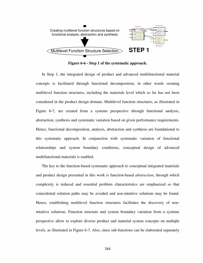
384
Multilevel Function Structure Selection
Creating multilevel function structures based on
functional analysis, abstraction and synthesis
STEP 1
Advanced multifunctional material
Ex,in
Mx,in
Ex,in
System boundary
System function x Exyz,out
System function z
System function y
Ey,in
Sz,in
Mx,in Sub-system function xx
Ex,out
Sub-system function xy
Sz,in
Ey,in Material function yx
Eyz,out
Material function zx
Sub-system boundarySystem level
Sub-system level
Material level
Figure 6-6 - Step 1 of the systematic approach.
In Step 1, the integrated design of product and advanced multifunctional material
concepts is facilitated through functional decomposition, in other words creating
multilevel function structures, including the materials level which so far has not been
considered in the product design domain. Multilevel function structures, as illustrated in
Figure 6-7, are created from a systems perspective through functional analysis,
abstraction, synthesis and systematic variation based on given performance requirements.
Hence, functional decomposition, analysis, abstraction and synthesis are foundational to
this systematic approach. In conjunction with systematic variation of functional
relationships and system boundary conditions, conceptual design of advanced
multifunctional materials is enabled.
The key to the function-based systematic approach to conceptual integrated materials
and product design presented in this work is function-based abstraction, through which
complexity is reduced and essential problem characteristics are emphasized so that
coincidental solution paths may be avoided and non-intuitive solutions may be found.
Hence, establishing multilevel function structures facilitates the discovery of non-
intuitive solutions. Function structure and system boundary variation from a systems
perspective allow to explore diverse product and material system concepts on multiple
levels, as illustrated in Figure 6-7. Also, since sub-functions can be elaborated separately
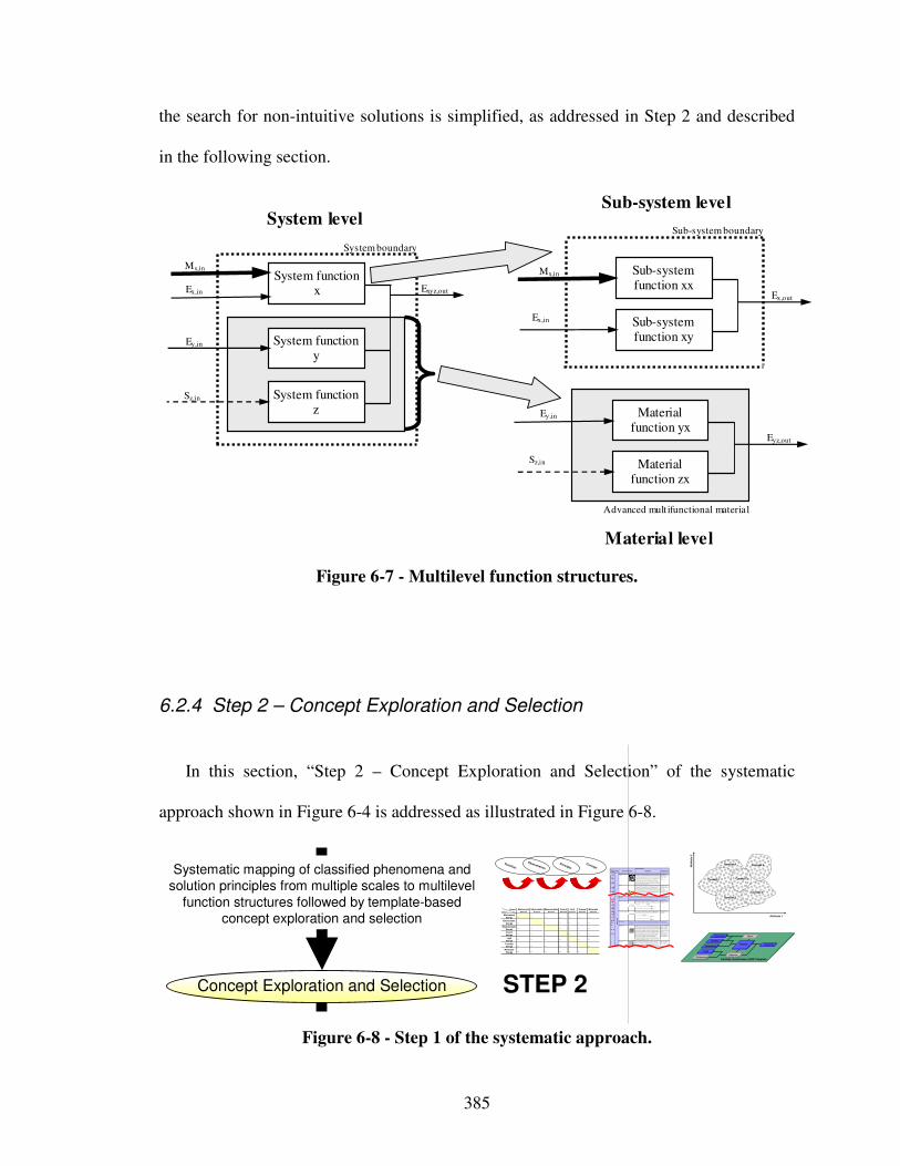
385
the search for non-intuitive solutions is simplified, as addressed in Step 2 and described
in the following section.
Advanced mult ifunctional material
Ex,in
Mx,in
Ex,in
System boundary
System function x Exyz,out
System function z
System function y
Ey,in
Sz,in
Mx,in Sub-system function xx
Ex,out
Sub-system function xy
Sz,in
Ey,in Material function yx
Eyz,out
Material function zx
Sub-system boundary System level
Sub-system level
Material level
Figure 6-7 - Multilevel function structures.
6.2.4 Step 2 – Concept Exploration and Selection
In this section, “Step 2 – Concept Exploration and Selection” of the systematic
approach shown in Figure 6-4 is addressed as illustrated in Figure 6-8.
Concept Exploration and Selection
Systematic mapping of classified phenomena and solution principles from multiple scales to multilevel
function structures followed by template-based concept exploration and selection
STEP 2
Output
Input
Mechanical
Energy… … … … … … …
Electrostatic
Energy… … … … … …
Magnetostatic
Energy… … … … … …
Sound
Energy… … … … … …
Light
Energy… … … … … …
ThermalEnergy
… … … … … …
Molecular
Energy… … … … … …
Light
Energy
Thermal
Energy
Molecular
Energy
Mechanical
Energy
Electrostatic
Energy
Magnetostatic
Energy
Sound
Energy
Pheno-menon
Scale Properties Applications
"Mo nolit hic" m ater ials
- Metals Com pared to all o ther classes of m aterial, me tals are stiff, str ong and tough, but th ey are hea vy. T hey have re la tively high m eltin g points. Only one m etal - gold - is
che mically stab le as a metal. M etals are ductile, a llowing them to be sha ped by
r olling , forging, drawingn and e xt rusion. T hey are easy to m achine with precision,
a nd they can be jo ine d in many differ ent ways. Iron a nd nickel are tr ansitional
m etals involving both me tallic and covalent bonds, a nd tend to be less ductile than o ther me tals. Ho wever , metals cond uct electricity well, re flect lig ht and ar e
com pletely opaque. Prima ry produ ct ion of meta ls is ene rgy intensive. Many
r equire at le ast twice a s much ener gy per un it weight than comm odity polymers.
But, m etals can gener ally be recycled and the energy r equired to do so is much
less tha n that re quried fo r primar y production. Som e are to xic, ot hers are so inert
th at they can be im planted in the human b ody.
- Alum in um-, cop per-, m agnesium- , nickel-, steel-,
t ita niu m-, zinc-alloys
- Carbon- , stainles-, …
ste els
- Am orphou s metals, …
Ela
sti
c/in
ela
sti
c d
efo
rmati
on
(te
nsio
n, c
om
pre
ssio
n, b
end
ing
, sh
ear, to
rsio
n, bu
ck
ling
, fr
actu
re, c
utt
ing
, in
vers
ion, e
xtr
usio
n,
Characteristics
Solution Principle
- Polymer s
F rom a macroscale, m onolithic mater ia ls a re ref erred to as matte r, i.e., the su bstance of which physical objects ar e composed.
Polymers fe ature a n immense r ange of form, co lor , surface finish , translucency,
tr anspare ncy, toughness an d flexibility. Ease of mo ld ing allo ws shap es that in
o ther ma terials could only be built up by expensive assembly meth ods. The ir
e xce llent wor kability allows the m oldin g of comp lex f orms, allowing cheap m anufactur e of integr ated com ponents that previously we re mad e by assembling
m any parts. M any polymers ar e cheap bo th to buy and shape. Most resist wa ter,
a cids a nd alkalis well, thou gh orga nic so lven ts attack some. All are light a nd many
a re flexible. Th eir prope rties change rapidly with t empera ture. Even at r oom
te mpera ture ma ny cr eep and whe n cooled they m ay become br ittle . Polymer s g enerally are sen sitive to UV radiation and to str ongly oxidizing e nvir onment s.
- The rmosplastic polymer s:
ABS, Cellulose, Ionom ers,
Nylon/PA, PC, PEEK, PE,
PMMA, POM, PP, PS, PTF E, t pPVC, tpPU,
PET/PETE/PBT
- The rmosetting polym ers:
Epoxy, Phenolic, Po lyester ,
t sPU, tsPVC - Elastom ers: Acrylic
m achining.
Hon eycom b-co re
san dwich es
- In-plane h oneycombs Cor e cell axes of in-plane honeycomb cor es are o riented pa rallel to the fa ce -she ets. They pr ovide potentials for decrea se d conductivity and fluid flow within
cells. Relative densities ra nge from 0.001 to 0.3. Th eir densification str ain can be
a pproximate d as:
T heir r ela tive st iff ness can be ap proximated as:
T heir r ela tive st rength ca n be appr oximated as:
- Pr ism atic-, squar e-, ch ir acal-, etc. cor e in-plane
h oneycombs
- Out-of- plane honeycom bs Cor e cell axes of out- of-plane honeycomb cor es are or iented per pendicular to
f ace-sheets. T hey provide p otentials for d ecreased con ductivity. Relative densities
r ange fr om 0.00 1 to 0.3. T heir den sification st rain can be a pproximate d as:
T heir r ela tive st iff ness can be ap proximated as:
T heir r ela tive st rength ca n be appr oximated as:
- Hexagonal-, sq aure- , etc.
co re put- of-plane
h oneycombs
F iber -com pos ites
- Con tin uous fiber
comp osit es
Continu ous fiber com posites are com posites with highest stiffness an d strength .
T hey are made of co ntinuous fiber s usually em bedded in a therm osetting resin. T he fiber s carry the m echanical loads while the ma trix mater ia l t ransmits loads to
th e fibers and provides ductility and tou ghness as well as protecting the fibers
f rom da mage caused by handling or the environm ent. It is the m atrix mate rial that
limits the service temper ature and pro ce ssing conditions. On meso sca les, the
p ropert ies ca n be stron gly influen ced by the choice of fiber and matrix and the way in which these ar e combined : fiber-r esin ratio, fibe r length, f ibe r orienta tio n,
lam in ate thickness and t he presen ce of fiber/r esin coupling agen ts to impro ve
b onding. Th e strength of a comp osit e is in cr eased by ra ising the fiber- resin ratio,
a nd orienting the fibers pa rallel to the laoding direction. Incr eased laminate
th ickne ss lea ds to redu ced composite str ength an d modulus as t here is an
incr eased likelih ood of en trapped vo id s. Environ mental conditions af fect the p erform ance of com posites: fatigue loa ding, moistur e and hea t all
r educe allowable stren gth. Polyeste rs are th e most m ost widely used matrices as
th ey offer r easonable pr operties a t relatively lo w cost. The supe rior pr operties of
e poxies and the t ermper ature perfor mance of p olyimide s ca n justify their use in
cer tain applications, but they are exp ensive .
- Glass fibers [high st rength
a t low co st] , polymer fiber s ( organ ic ( e.g., Kevlar) or
a norganic ( e.g., Nylo n,
Polyester) ) [rea so nable
p roper tie s at relatively low
co st ], carbon f ib ers [very high str ength, stiffn ess and low
d ensity]
- Str ands, filamen ts, fibers,
yar ns (twisted stran ds),
r ovings (bund le d strands)
- Nonwoven matting s, weaves, braids, knits, othe r
- Discontinuo us fiber
comp osit es
Polymers r einforced with chop ped polymer , wo od, glass or car bon fiber s are
r eferr ed to as discontinuo us fiber com posites. The lo nger the fiber, the more
e fficien t is the reinfor cement a t carrying the applied loads, but shorter fibers are
e asie r to pr ocess and hence cheaper. Hen ce , fiber length and mat erial are th e
g overning design va riables. However, fibro us core com posites featur e shape f lexibility and re la tively high b ending stiffness at low den sity.
- Glass fibers, po lyme r fibers
( organ ic ( e.g., Kevlar) or
a norganic ( e.g., Nylo n,
Polyester) ), carbo n fibers
Mes
os
cale
Ela
stic
/ine
las
tic d
efo
rmat
ion
(ten
sion
, com
pre
ssio
n, b
end
ing
, she
ar, t
ors
ion
, bu
ckli
ng, f
ract
ure
, cu
ttin
g, in
vers
ion
, ext
rusi
on
, dra
win
g,
flow
)
Honeycom b-core sa ndwiche s take their n ame fr om their visual r esemblance to a bee's honeycomb . With controllable core dimensions
an d topologies on mesoscales, they fr eature r elatively h igh stif fness and yield stren gth at low density. Lar ge compr essive st rains are
ach ievab le at nominally constant st ress (befo re the m aterial comp acts), yielding a pote ntially high e nergy absor ption capacity. Honeycomb-
cor e sandwiches have accept able structur al perfor mance at relatively low costs with useful com binations of the rmoph ysical and m echanical prope rties. Usually, t hey provide ben efits with r espect to m ultip le use.
T he combina tio n of polymer s or othe r matr ix m aterials with fibers ha s give n a rang e of light mat erials with stiff ness and stre ngth
com parable t o that of m etals. Common ly, r esin mater ials ar e epoxies, polyester s and vinyls. Fibers ar e much str onger and stiffer t han
th eir equivalent in bulk fo rm beca use the dr awing process by they ar e made o rients the po lym er chains along t he fiber a xis or reduces t he de nsit y o f defects.
−≈
s
D ρρ
ε 4.11
31 rel
sE
Eρ≈
rel
ys
y ρσ
σ5.0≈
rel
sE
Eρ1≈
rel
ys
y ρσ
σ1≈
−≈
s
D ρρ
ε 4.11
Goals
PreferencesPreferences
Variables
Parameters
Constraints
Response
ObjectiveObjective
Analysis
DriverDriver
Partially Instantiated cDSP Template
Att
rib
ute
2
Attribute 1
Concept 2
Concept 5
Concept 1 Concept 3
Concept 6
Concept 4Concept
Principle
Phenomenon
Function
Figure 6-8 - Step 1 of the systematic approach.
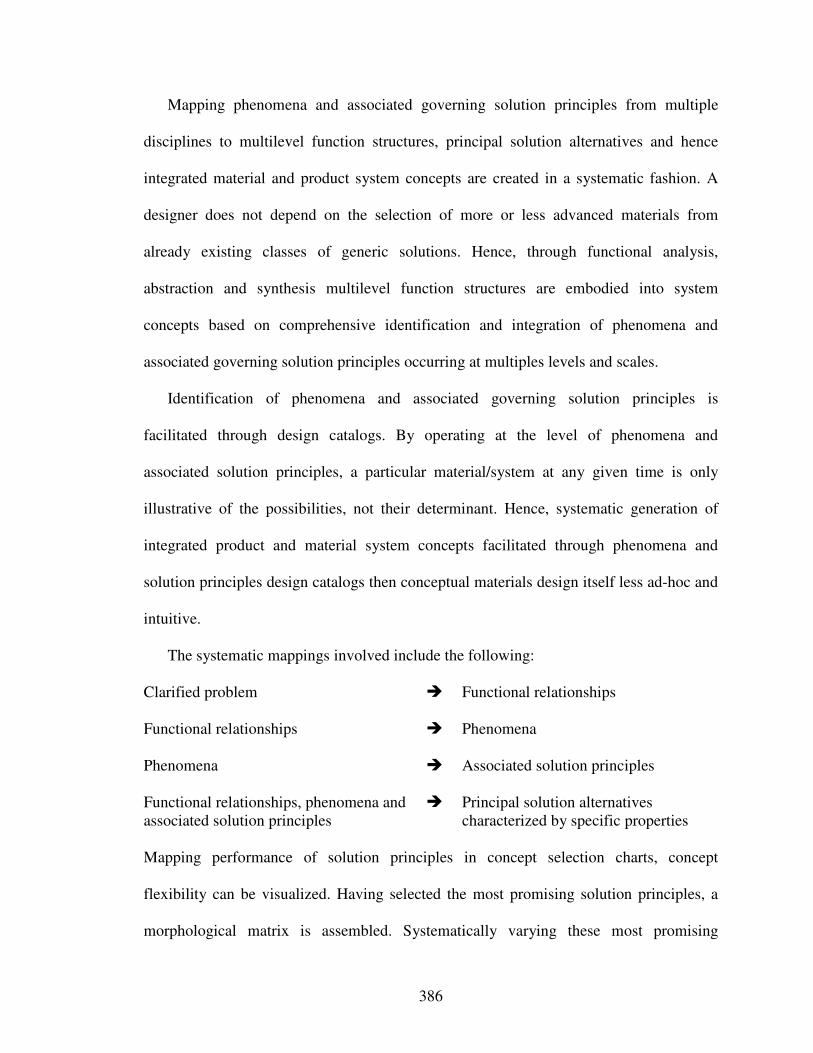
386
Mapping phenomena and associated governing solution principles from multiple
disciplines to multilevel function structures, principal solution alternatives and hence
integrated material and product system concepts are created in a systematic fashion. A
designer does not depend on the selection of more or less advanced materials from
already existing classes of generic solutions. Hence, through functional analysis,
abstraction and synthesis multilevel function structures are embodied into system
concepts based on comprehensive identification and integration of phenomena and
associated governing solution principles occurring at multiples levels and scales.
Identification of phenomena and associated governing solution principles is
facilitated through design catalogs. By operating at the level of phenomena and
associated solution principles, a particular material/system at any given time is only
illustrative of the possibilities, not their determinant. Hence, systematic generation of
integrated product and material system concepts facilitated through phenomena and
solution principles design catalogs then conceptual materials design itself less ad-hoc and
intuitive.
The systematic mappings involved include the following: Clarified problem � Functional relationships
Functional relationships � Phenomena
Phenomena � Associated solution principles
Functional relationships, phenomena and associated solution principles
� Principal solution alternatives characterized by specific properties
Mapping performance of solution principles in concept selection charts, concept
flexibility can be visualized. Having selected the most promising solution principles, a
morphological matrix is assembled. Systematically varying these most promising
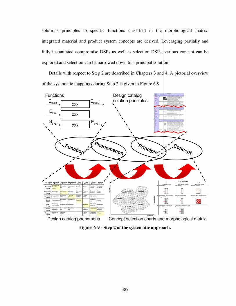
387
solutions principles to specific functions classified in the morphological matrix,
integrated material and product system concepts are derived. Leveraging partially and
fully instantiated compromise DSPs as well as selection DSPs, various concept can be
explored and selection can be narrowed down to a principal solution.
Details with respect to Step 2 are described in Chapters 3 and 4. A pictorial overview
of the systematic mappings during Step 2 is given in Figure 6-9.
Concept
Principle
Phenomenon
Function
xxxExxx
EyyySyyy yyy
Functions
Output
Input
Mechanical
Energy
(In)elastic de-
formation
Inertia
…
Electrostric-
tion
…
Magnetostric-
tion
…
Impact
…
Friction
…
Pressure
change
…
Dislocation
hardening
…
Electrostatic
Energy
Electric field
…
Interference
…
Hall-effect
…
Electrostric-
tion
…
Photostric-
tion
…
Electrical
resistance
…
Galvanic
element
…
Magnetostatic
Energy
Magnetic field
…
Oscillating
circuit
…
Ferromag-
netism
…
Magneto-
striction
…
Farraday-
effect
…
Eddy current
…
Sound
Energy
Pressure wave
…
Electrostric-
tion
…
Magnetostric-
tion
…
Reflection
…
Noise dam-
ping
…
Elasticity
…
Light
Energy
Electromag-
netic radiation
…
Photostric-tion
…
Absorption
…
Refraction
…
Thermolumi-
nescence
…
Photoeffect
…
Thermal
Energy
Thermal
expansion
…
Thermoelectri
city
…
Curie-Weiss
law
…
Pyro-
electricity
…
Convection
…
Phase trans-
formation
…
Molecular
Energy
Exothermic
reaction
…
Molecular
dipoloe
…
Fluores-
cence
…
Combustion
Conductivity
…
Adhesion
…
Light
Energy
Thermal
Energy
Molecular
Energy
Mechanical
Energy
Electrostatic
Energy
Magnetostatic
Energy
Sound
Energy
Design catalog
solution principles
Design catalog phenomena
xxxExxx1 Exxx2
Pheno-
menonScale Properties Applications
"Monolithic" materials
- Metals Compared to all other classes of material, metals are stiff, strong and tough, but
they are heavy. They have relatively high melting points. Only one metal - gold - is
chemically stable as a metal. Metals are ductile, allowing them to be shaped by
rolling, forging, drawingn and extrusion. They are easy to machine with precision,
and they can be joined in many dif ferent ways. Iron and nickel are transitional
metals involving both metallic and covalent bonds, and tend to be less ductile than
other metals. However, metals conduct electricity well, reflect light and are
completely opaque. Primary production of metals is energy intensive. Many
require at least twice as much energy per unit weight than commodity polymers.
But, metals can generally be recycled and the energy required to do so is much
less than that requried for primary production. Some are toxic, others are so inert
that they can be implanted in the human body.
- Alum inum-, copper-,
magnesium-, nickel-, steel-,
titanium-, zinc-alloys
- Carbon-, stainles-, …
steels
- Amorphous metals, …
Ela
sti
c/in
ela
sti
c d
efo
rma
tio
n (
tensio
n, co
mp
ress
ion
, b
en
din
g, s
he
ar,
to
rsio
n, b
ucklin
g, fr
actu
re, c
utt
ing, in
ve
rsio
n, extr
usio
n,
Characteristics
Solution Principle
- Polymers
From a macroscale, monolithic materials are referred to as matter, i.e., the substance of which physical objects are composed.
Polymers f eature an immense range of form, color, surface finish, translucency,
transparency, toughness and flexibility. Ease of molding allows shapes that in
other materials could on ly be built up by expensive assembly methods. Their
excellent workability allows the molding of complex forms, allowing cheap
manufacture of integrated components that previously were made by assembling
many parts. Many polymers are cheap both to buy and shape. Most resist water,
acids and alkalis well, though organic solvents attack some. All are light and many
are flexible. Their properties change rapidly with temperature. Even at room
temperature many creep and when cooled they may become brittle. Polymers
generally are sensitive to UV radiation and to strongly oxidizing environments.
- Thermosplastic polymers:
ABS, Cellulose, Ionomers,
Nylon/PA, PC, PEEK, PE,
PMMA, POM, PP, PS, PTFE,
tpPVC, tpPU,
PET/PETE/PBT
- Thermosetting polymers:
Epoxy, Phenolic, Polyester,
tsPU, tsPVC
- Elastomers: Acrylic
machining.
Honeycomb-core sandwiches
- In-plane honeycombs Core cell axes of in-plane honeycomb cores are oriented parallel to the f ace-
sheets. They provide potentials for decreased conductivity and fluid flow within
cells. Relative densities range from 0.001 to 0.3. Their densificat ion strain can be
approximated as:
Their relative stiffness can be approximated as:
Their relative strength can be approximated as:
- Prismatic-, square-,
chiracal-, etc. core in-plane
honeycombs
- Out-of-plane honeycombs Core cell axes of out-of-plane honeycomb cores are oriented perpendicular to
face-sheets. They provide potentials for decreased conductivity. Relative densities
range from 0.001 to 0.3. Their densification strain can be approximated as:
Their relative stiffness can be approximated as:
Their relative strength can be approximated as:
- Hexagonal-, sqaure-, etc.
core put-of-plane
honeycombs
Fiber-composites
- Continuous f iber
composites
Continuous fiber composites are composites with highest stiffness and strength.
They are made of continuous fibers usually embedded in a thermosetting resin.
The fibers carry the mechanical loads while the matrix material transm its loads to
the f ibers and provides ductility and toughness as well as protecting the fibers
from damage caused by handling or the environment. It is the matrix material that
limits the service temperature and processing conditions. On mesoscales, the
properties can be strongly influenced by the choice of fiber and matrix and the
way in which these are combined: fiber-resin ratio, fiber length, fiber orientation,
laminate thickness and the presence of fiber/resin coupling agents to improve
bonding. The strength of a composite is increased by raising the fiber-resin ratio,
and orienting the fibers parallel to the laoding direction. Increased laminate
thickness leads to reduced composite strength and modulus as there is an
increased likelihood of entrapped voids. Environmental conditions affect the
performance of composites: fatigue loading, moisture and heat all
reduce allowable strength. Polyesters are the most most widely used matrices as
they offer reasonable properties at relatively low cost. The superior properties of
epoxies and the termperature performance of polyimides can justify their use in
certain applications, but they are expensive.
- Glass fibers [high strength
at low cost], polymer fibers
(organic (e.g., Kevlar) or
anorganic (e.g., Nylon,
Polyester)) [reasonable
properties at relatively low
cost], carbon fibers [very high
strength, stiffness and low
density]
- Strands, filaments, fibers,
yarns (twisted strands),
rovings (bundled strands)
- Nonwoven mattings,
weaves, braids, knits, other
- Discontinuous fiber
composites
Polymers reinforced with chopped polymer, wood, glass or carbon fibers are
referred to as discontinuous fiber composites. The longer the fiber, the more
eff icient is the reinforcement at carrying the applied loads, but shorter f ibers are
easier to process and hence cheaper. Hence, fiber length and material are the
governing design variables. However, fibrous core composites feature shape
flexibility and relatively h igh bending stiffness at low density.
- Glass fibers, polymer fibers
(organic (e.g., Kevlar) or
anorganic (e.g., Nylon,
Polyester)), carbon f ibers
Me
so
sc
ale
Ela
sti
c/i
ne
las
tic d
efo
rma
tio
n (
ten
sio
n, c
om
pre
ss
ion
, b
en
din
g,
sh
ear,
to
rsio
n, b
uc
kli
ng
, fr
actu
re, c
utt
ing,
inv
ersio
n,
ex
tru
sio
n, d
raw
ing
,
flo
w)
Honeycomb-core sandwiches take their name from their visual resemblance to a bee's honeycomb. With controllable core dimensions
and topologies on mesoscales, they freature relatively high stiffness and yield strength at low density. Large compressive strains are
achievable at nom inally constant stress (before the material compacts), yielding a potentially high energy absorption capacity. Honeycomb-
core sandwiches have acceptable structural perf ormance at relatively low costs with useful combinations of thermophysical and
mechanical properties. Usually, they provide benefits with respect to multiple use.
The combination of polymers or other matrix materials with fibers has given a range of light materials with stiffness and strength
comparable to that of metals. Commonly, resin materials are epoxies, polyesters and vinyls. Fibers are much stronger and stiffer than
their equivalent in bulk form because the drawing process by they are made orients the polymer chains along the fiber axis or reduces the
density of defects.
−≈
s
Dρ
ρε 4.11
31 rel
sE
Eρ≈
re l
ys
y ρσ
σ5.0≈
re l
sE
Eρ1≈
rel
ys
y ρσ
σ1≈
−≈
s
Dρ
ρε 4.11
Concept selection charts and morphological matrix
A B C
Dissipate Energy Store (Strain) Energy Store (Use) Energy
1 Plate bending Plate bending Reactive materials
2 Plate bending + Out-Of-Plane
Honeycomb Core
Stiffened plate bending Reactive Metal Powder Mixtures
3 Plate bending + Closed-Cell
Foam Core
Out-Of-Plane Honeycomb Core
Sandwich
Alt
ern
ati
ve
Core Function
Att
rib
ute
2
Attribute 1
Concept 2
Concept 5
Concept 1 Concept 3
Concept 6
Concept 4
Figure 6-9 - Step 2 of the systematic approach.
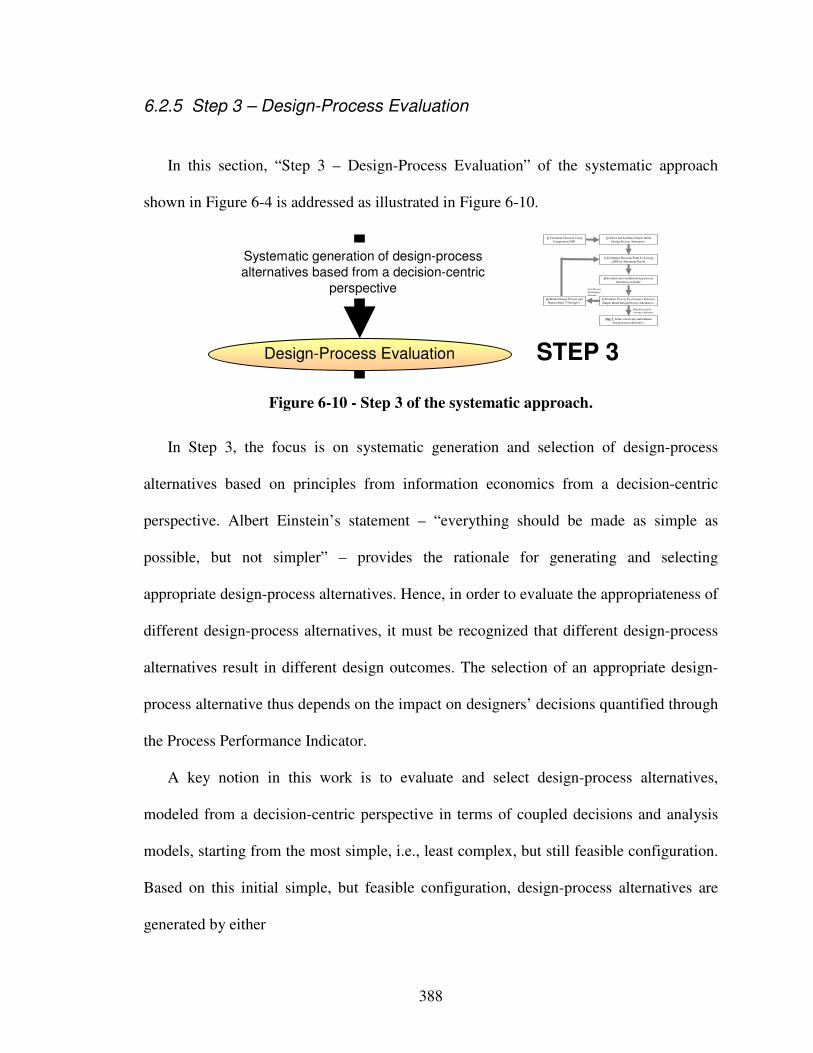
388
6.2.5 Step 3 – Design-Process Evaluation
In this section, “Step 3 – Design-Process Evaluation” of the systematic approach
shown in Figure 6-4 is addressed as illustrated in Figure 6-10.
Design-Process Evaluation STEP 3
Systematic generation of design-process
alternatives based from a decision-centric
perspective
2) Select and Evaluate Simple Initial
Design Process Alternative.
4) Evaluate most truthful design process
alternative available.
Step 7: Select satisficing embodiment
design process alternative.
1) Formulate Decision Using
Compromise DSP.
3) Determine Decision Point by Solving
cDSP for Maximum Payoff.
High Process Per-
formance Indicator
Low Process
Performance
Indicator
5) Evaluate Process Performance Indicator
Simple Initial Design-Process Alternative .
6) Refine Design-Process and
Repeat Steps 3 Through 5.
Figure 6-10 - Step 3 of the systematic approach.
In Step 3, the focus is on systematic generation and selection of design-process
alternatives based on principles from information economics from a decision-centric
perspective. Albert Einstein’s statement – “everything should be made as simple as
possible, but not simpler” – provides the rationale for generating and selecting
appropriate design-process alternatives. Hence, in order to evaluate the appropriateness of
different design-process alternatives, it must be recognized that different design-process
alternatives result in different design outcomes. The selection of an appropriate design-
process alternative thus depends on the impact on designers’ decisions quantified through
the Process Performance Indicator.
A key notion in this work is to evaluate and select design-process alternatives,
modeled from a decision-centric perspective in terms of coupled decisions and analysis
models, starting from the most simple, i.e., least complex, but still feasible configuration.
Based on this initial simple, but feasible configuration, design-process alternatives are
generated by either
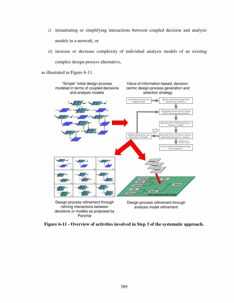
389
i) instantiating or simplifying interactions between coupled decision and analysis
models in a network, or
ii) increase or decrease complexity of individual analysis models of an existing
complex design-process alternative,
as illustrated in Figure 6-11.
X1 Y1
X2 Y2
X1
Y1
X2 Y2
Analysis i
Goals
Pre ferences
Vari ables
Parameters
Constra ints
R esponse
Obj ect ive
Fully Instantia ted cDSP Tem plate
Driver
Ana lysis
Goa ls
Pre ferences
Vari ables
Parameters
Constra ints
R esponse
Obj ect ive
Fully Instantia ted cDSP Tem plate
Driver
Ana lysis
Analysis i
Goals
Pre ferences
Vari ables
Parameters
Constra ints
R esponse
Obj ect ive
Fully Instantia ted cDSP Tem plate
Driver
Ana lysis
Analysis i
X1 Y1
X1 Y1 X1 Y1
G oals
Preferences
Variables
Parameters
Constrai nts
Response
Objecti ve
Fully Ins tantiated cDSP Template
Dri ver
Anal ysi s
G oa ls
Preferences
Variables
Parameters
Constrai nts
Response
Objecti ve
Fully Ins tantiated cDSP Template
Dri ver
Anal ysi s
Goa ls
Pre ferences
Vari ables
Parameters
Constra ints
R esponse
Obj ect ive
Fully Instantia ted cDSP Tem plate
Driver
Ana lysis
Goals
Pre ferences
Vari ables
Parameters
Constra ints
R esponse
Obj ect ive
Fully Instantia ted cDSP Tem plate
Driver
Ana lysis
Goals
Pre ferences
Vari ables
Parameters
Constra ints
R esponse
Obj ect ive
Fully Instantia ted cDSP Tem plate
Driver
Ana lysis
Analysis i
X1 Y1
Analysis i
Analysis i
Analysis i
Goals
Preferences
Variables
Parameters
Constraints
Response
Objective
Analysis 1
Fully Instantiated cDSP Template
Driver
Analysis 2
Analysis i
Goals
Preferences
Variables
Parameters
C onstraints
Response
O bjective
Fully Insta nt iate d cDSP Te mplate
Driver
Analysis
Goals
Preferences
Variables
Parameters
C onstraints
Response
O bjective
Fully Insta nt iate d cDSP Te mplate
Driver
Analysis
P1 P2 P3
P6
P9P8P7
P4 P5
Validation
X1 Y1
X2 Y2
X1 Y1
X2 Y2
X1
Y1
X2 Y2
Analysis i
Goals
Preferences
Variables
Parameters
C onstraints
Response
O bjective
Fully Insta nt iate d cDSP Te mplate
Driver
Analysis
Goals
Preferences
Variables
Parameters
Constraints
Response
Objective
Fully Ins tantia ted cDSP Templ ate
Driver
A nalysis
Analysis i
Goals
Preferences
Variables
Parameters
Constraints
Response
Objective
Fully Ins tantia ted cDSP Templ ate
Driver
A nalysis
Analysis i
Goals
Preferences
Variables
Parameters
Constraints
Response
Objective
Fully Ins tantia ted cDSP Templ ate
Driver
A nalysis
X1 Y1 X1 Y1 X1 Y1
Goals
Preferences
Variables
Parameters
C onstraints
Response
O bjective
Fully Insta nt iate d cDSP Te mplate
Driver
Analysis Goals
Preferences
Variables
Parameters
Constraints
Response
Objective
Fully Ins tantia ted cDSP Templ ate
Driver
A nalysis
Goals
Preferences
Variables
Parameters
C onstraints
Response
O bjective
Fully Insta nt iate d cDSP Te mplate
Driver
Analysis
Goals
Preferences
Variables
Parameters
C onstraints
Response
O bjective
Fully Insta nt iate d cDSP Te mplate
Driver
Analysis
Goals
Preferences
Variables
Parameters
Constraints
Response
Objective
Fully Ins tantia ted cDSP Templ ate
Driver
A nalysis
X1 Y1
X2 Y2
X1 Y1
X2 Y2
X1
Y1
X2 Y2
Goals
Preferences
Variables
Parameters
Constraints
Response
Objective
Fully Ins tantia ted cDSP Templ ate
Driver
A nalysis
Goals
Preferences
Variables
Parameters
C onstraints
Response
O bjective
Fully Insta nt iate d cDSP Te mplate
Driver
Analysis Goals
Preferences
Variables
Parameters
Constraints
Response
Objective
Fully Ins tantia ted cDSP Templ ate
Driver
A nalysis
Goals
Preferences
Variables
Parameters
C onstraints
Response
O bjective
Fully Insta nt iate d cDSP Te mplate
Driver
Analysis
Goals
Preferences
Variables
Parameters
C onstraints
Response
O bjective
Fully Insta nt iate d cDSP Te mplate
Driver
Analysis
Goals
Preferences
Variables
Parameters
Constraints
Response
Objective
Fully Ins tantia ted cDSP Templ ate
Driver
A nalysis
Goals
Preferences
Variables
Parameters
Constraints
Response
Objective
Fully Ins tantia ted cDSP Templ ate
Driver
A nalysis
Goals
Preferences
Variables
Parameters
Constraints
Response
Objective
Fully Ins tantia ted cDSP Templ ate
Driver
A nalysis
Goals
Preferences
Variables
Parameters
C onstraints
Response
O bjective
Fully Insta nt iate d cDSP Te mplate
Driver
Analysis
Goals
Preferences
Variables
Parameters
C onstraints
Response
O bjective
Fully Insta nt iate d cDSP Te mplate
Driver
Analysis
Goals
Preferences
Variables
Parameters
Constraints
Response
Objective
Fully Ins tantia ted cDSP Templ ate
Driver
A nalysis
Goals
Preferences
Variables
Parameters
Constraints
Response
Objective
Fully Ins tantia ted cDSP Templ ate
Driver
A nalysis
Goals
Preferences
Variables
Parameters
Constraints
Response
Objective
Fully Ins tantia ted cDSP Templ ate
Driver
A nalysis Goals
Preferences
Variables
Parameters
Constraints
Response
Objective
Fully Ins tantia ted cDSP Templ ate
Driver
A nalysis
Goals
Preferences
Variables
Parameters
Constraints
Response
Objective
Fully Ins tantia ted cDSP Templ ate
Driver
A nalysis
Goals
Preferences
Variables
Parameters
C onstraints
Response
O bjective
Fully Insta nt iate d cDSP Te mplate
Driver
Analysis
B) Select and Evaluate Simple Initial
Design-Process Alternative.
D) Evaluate Most Truthful Design-Process
Alternative Available.
G: Select Satisficing Embodiment Design-
Process Alternative.
A) Formulate Decision Using
Compromise DSP.
C) Determine Decision Point by Solving
cDSP for Maximum Expected Payoff.
High Process Per-
formance Indicator
Low Process
Performance
Indicator
E) Evaluate Process Performance Indicator
Simple Initial Design-Process Alternative .
F) Refine Design-Process and
Repeat Steps C Through E.
“Simple” initial design-process modeled in terms of coupled decisions
and analysis models
Value-of-information-based, decision-centric design-process generation and
selection strategy
Design-process refinement through
analysis model refinement
Design-process refinement through refining interactions between
decisions or models as proposed by Panchal
Figure 6-11 - Overview of activities involved in Step 3 of the systematic approach.
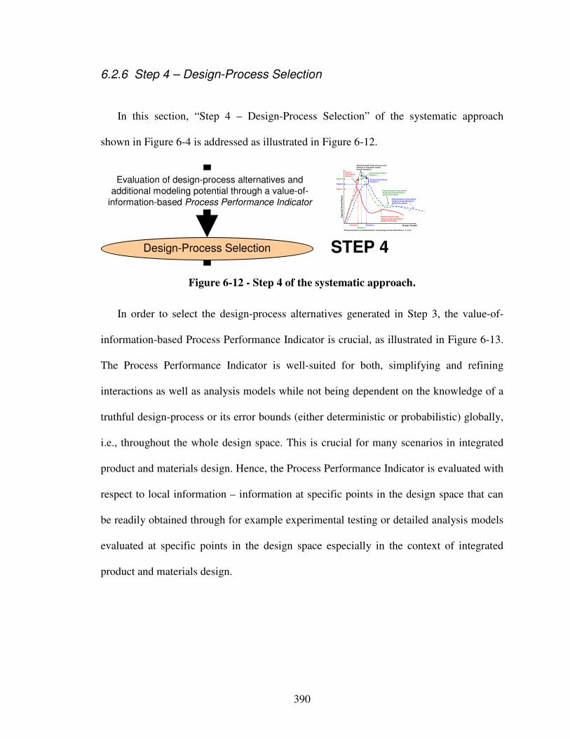
390
6.2.6 Step 4 – Design-Process Selection
In this section, “Step 4 – Design-Process Selection” of the systematic approach
shown in Figure 6-4 is addressed as illustrated in Figure 6-12.
Evaluation of design-process alternatives and
additional modeling potential through a value-of-
information-based Process Performance Indicator
Design-Process Selection STEP 4
Design Variable
Exp
ecte
d O
ve
rall
Pa
yo
ff
Expected payoff using
design process alternative 1(global information)
Expected payoff using refined design process alternative 2(global information)
Payoff 2
Decision 1 Decision 2
Payoff 1
Process Performance Indicator 1
Expected payoff using most accurate physical or simulation models(local information)
Process Performance Indicator 2
Decisions based on predicted behavior using design process alternatives 1, 2, 3, etc.
Process Performance Indicator 3
Expected payoff using refined design process alternative 3(global information)
Payoff 3
Decision 3
Figure 6-12 - Step 4 of the systematic approach.
In order to select the design-process alternatives generated in Step 3, the value-of-
information-based Process Performance Indicator is crucial, as illustrated in Figure 6-13.
The Process Performance Indicator is well-suited for both, simplifying and refining
interactions as well as analysis models while not being dependent on the knowledge of a
truthful design-process or its error bounds (either deterministic or probabilistic) globally,
i.e., throughout the whole design space. This is crucial for many scenarios in integrated
product and materials design. Hence, the Process Performance Indicator is evaluated with
respect to local information – information at specific points in the design space that can
be readily obtained through for example experimental testing or detailed analysis models
evaluated at specific points in the design space especially in the context of integrated
product and materials design.
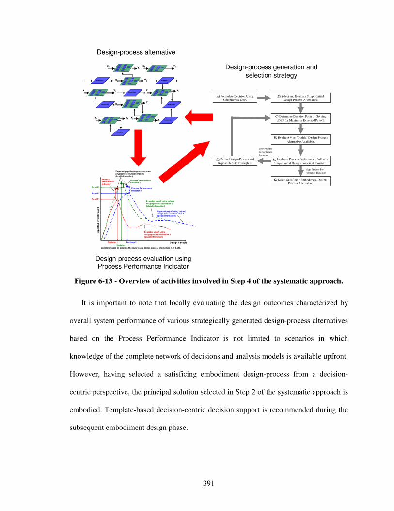
391
X1 Y1
X2 Y2
X1
Y1
X2 Y2
Analysis i
Goals
Preferences
Variables
Parameters
Constraints
R esponse
Objective
Fully Instantiated cDSP Template
D ri ver
Anal ysis
Goals
Preferences
Variables
Parameters
Constraints
R esponse
Objective
Fully Instantiated cDSP Template
D ri ver
Anal ysis
Analysis i
Goals
Preferences
Variables
Parameters
Constraints
R esponse
Objective
Fully Instantiated cDSP Template
D ri ver
Anal ysis
Analysis i
X1 Y1
X1 Y1 X1 Y1
Goals
Preferences
Variables
Parameters
Constraints
R esponse
Objective
Fully Instantiated cDSP Template
D ri ver
Anal ysis
Goals
Preferences
Vari ables
Parameters
Constrai nts
Response
Objective
Fully Inst antiated cDSP Template
Driver
Analysis
Goals
Preferences
Vari ables
Parameters
Constrai nts
Response
Objective
Fully Inst antiated cDSP Template
Driver
Analysis
Goals
Preferences
Variables
Parameters
Constraints
R esponse
Objective
Fully Instantiated cDSP Template
D ri ver
Anal ysis
Goals
Preferences
Vari ables
Parameters
Constrai nts
Response
Objective
Fully Inst antiated cDSP Template
Driver
Analysis
Analysis i
X1 Y1
Analysis i
Analysis i
Analysis i
B) Select and Evaluate Simple Initial
Design-Process Alternative.
D) Evaluate Most Truthful Design-Process
Alternative Available.
G: Select Satisficing Embodiment Design-
Process Alternative.
A) Formulate Decision Using
Compromise DSP.
C) Determine Decision Point by Solving
cDSP for Maximum Expected Payoff.
High Process Per-
formance Indicator
Low Process
Performance
Indicator
E) Evaluate Process Performance Indicator
Simple Initial Design-Process Alternative .
F) Refine Design-Process and
Repeat Steps C Through E.
Design Variable
Ex
pe
cte
d O
ve
rall
Pa
yo
ff
Expected payoff usingdesign process alternative 1(global information)
Expected payoff using refined design process alternative 2(global information)
Payoff 2
Decision 1 Decision 2
Payoff 1
Process Performance Indicator 1
Expected payoff using most accurate physical or simulation models(local information)
Process Performance Indicator 2
Decisions based on predicted behavior using design process alternatives 1, 2, 3, etc.
Process Performance Indicator 3
Expected payoff using refined design process alternative 3(global information)
Payoff 3
Decision 3
Design-process evaluation using Process Performance Indicator
Design-process alternative
Design-process generation and
selection strategy
Figure 6-13 - Overview of activities involved in Step 4 of the systematic approach.
It is important to note that locally evaluating the design outcomes characterized by
overall system performance of various strategically generated design-process alternatives
based on the Process Performance Indicator is not limited to scenarios in which
knowledge of the complete network of decisions and analysis models is available upfront.
However, having selected a satisficing embodiment design-process from a decision-
centric perspective, the principal solution selected in Step 2 of the systematic approach is
embodied. Template-based decision-centric decision support is recommended during the
subsequent embodiment design phase.
392
6.3 On Original and Adaptive Design
The systematic approach to integrated product, materials and design-process design
developed in this work is focused on original design. However, the systematic approach
outlined in the previous sections is also applicable to adaptive design. Adaptive designs
outnumber original designs by far – also a result of common engineering sense. Hence,
developing a systematic approach that is applicable to adaptive design is crucial to foster
integrated product, materials and design-process design on a large scale and to achieve
concept flexibility.
Methods and tools to achieve concept flexibility are reviewed in Section 2.4,
specifically design for modularity [22, 198, 234, 264, 364, 420, 470, 496, 501, 503, 597,
604, 622, 674, 682, 684], design for mutability [287, 470, 591], and design for robustness
[85, 109, 112, 113, 117, 118, 129, 214, 409, 466, 467, 488, 640, 656-658, 757]. The use
of these methods and tools in the context of the systematic approach to integrated
product, materials, and design-process design developed in this work is summarized in
Table 2-7. Since in most cases, adaptive design deals with more cost efficient redesign,
which is predominantly realized through standardization, consider as an example the
design of hierarchical product platforms including the materials level. The goal of
designing hierarchical product platforms including the materials level is to introduce
standardization in complex engineering systems through materials design while
redesigning the system itself, i.e., decreasing cost through standardization while
improving or maintaining operational system performance through tailor-made materials.
In this context, the potential for standardization and redesign on multiple system
levels including the materials level can be identified through a domain-independent
393
approach to hierarchical platform design based on Numerical Taxonomy [614]. The
approach to hierarchical product platform design based on numerical taxonomy has been
developed by Pederson and coauthors [496]. Since this approach is based on the
systematic scientific method of numerical taxonomy, it has been generalized to facilitate
the domain independent design of hierarchical platforms in times when domain-
independency is becoming key to future platform design by Messer, Pederson and
coauthors [420]. Hence, this approach can be used to identify the potential for redesign
and materials design in adaptive design of complex engineering systems. For details on
this approach, the interested reader is referred to the literature [420].
6.4 On Verification and Validation of the Systematic Approach
In this chapter, theoretical structural validation as one aspect of the validation square
is addressed. An overview of the validation performed in this dissertation is presented in
Section 1.3. Specific details related to validating the function-based systematic approach
presented in this Chapter are illustrated in Figure 6-15.
394
6.4.1 Theoretical Structural Validity
Theoretical structural validation refers to accepting the validity and internal
consistency of individual constructs used in the systematic approach. Theoretical
structural validation of the individual constructs has been addressed in Sections 2.5, 3.6,
4.6, 5.6. Due to the logical procedure of literature review, gap analysis, as well as
development and evaluation of new constructs, the theoretical structural validity of the
individual constructs is accepted. Details are not repeated here. Accepting the internal
consistency of the way these constructs are put together is investigated in this Section.
Stepwise systematic approaches are well established and have been used frequently in
design practice as well as throughout the design literature. One particular example is the
Pahl and Beitz design-process. Although, steps are shown in sequence in Figure 1-3 and
other figures throughout this work, the design-process they represent is often iterative and
undertaken in a concurrent fashion. Also, systematic approaches are almost always
modular in that a designer may skip steps if applicable. Specific steps only represents
operational guidelines for actions.
The overall systematic approach developed in this work consists of two phases,
conceptual design, involving Steps 1 and 2, as well as meta-design, involving Steps 3 and
4. In the conceptual design phase, the systematic approach is executed to design
integrated products and material concepts; in the meta-design phase, associated
embodiment design-processes are designed. Hence, the conceptual design phase is
focused on concept generation and narrowing concept selection down to a principal
solution, whereas the meta design phase is focused on generating and selecting a
satisficing embodiment design-process for the principal solution identified earlier.
395
For the conceptual design phase, a function-based systematic approach to the
integrated design of product and material concepts, as illustrated in Figure 6-2, is
developed as the first component of the overall systematic approach. For the meta design
phase, a systematic value-of-information-based approach to design-process design from a
decision-centric perspective, as illustrated in Figure 6-3, is developed as the second
component of the overall systematic approach. Therefore, integration of both components
shows that the internal structure of the resulting systematic approach to the integrated
design of products, materials, and design-processes, as illustrated in Figure 6-4, is not
incompatible.
In fact, integrating both components results in a coherent succession of information
transformations and a coherent overall flow of information. However, the resulting
overall systematic approach is modular. For example, if a principal solution has already
been specified, the first conceptual design phase can be omitted and execution of the
overall systematic approach is focused on the systematic design of associated
embodiment design-processes.
The use of Decision Support Problems throughout both components of the overall
systematic approach facilitates integration in a manner that combines advantages of both
components. By using selection DSPs as well as partially and fully instantiated
compromise DSPs to narrow selection of concepts down to a principal solution, it is
possible to explore the conceptual design space comprehensively. Leveraging
compromise DSPs, it is possible generate families of solutions embodying a range of
tradeoff between multiple goals. After the compromise DSP is formulated, weights and
targets can be adjusted to shift emphasis among multiple goals or to modify the aspiration
396
space (defined by goal targets). Design variable bounds and constraint limits can also be
adjusted to shift the boundaries of the feasible design space. In addition, it is possible to
change the objective function formulation with possible formulations including
Archimedean, preemptive, and utility-based.
It is emphasized that in template-based DSPs, changes can be implemented by
changing values of respective building blocks. Also, as leveraged in the systematic
approach to design-processes design, building blocks, such as analysis models, may be
replaced completely. Hence, a designer is able to generate a variety of design-process
alternatives using compromise DSPs. It is important to note that actual details of for
example attribute ratings in selection DSPs or utility functions in utility-based
compromise DSPs are based on a designer’s preferences. Certainly, they affect the final
solution but not the application of the design methods developed in this work.
The systematic approach is intended to facilitate generation of integrated product and
material system concepts as well as the generation and selection of associated
embodiment design-processes. Generally, the systematic approach enables design of
materials and design-processes in the early conceptual phases of design. The overall goal
is to extend a designer’s concept and design-process flexibility. However, specifically,
the systematic approach is intended to extend:
• existing conceptual product design approaches by leveraging the potential
embedded in materials design and providing means for generating and selecting
embodiment design-processes,

397
• existing materials design approaches by allowing for function-based systematic
conceptual materials design and providing enhanced means for generating and
selecting embodiment design-processes,
• existing design-process design approaches by:
i) providing a systematic strategy for design-process generation and selection
from a decision-centric perspective,
ii) a value-of-information-based design-process performance indicator that is
useful in many scenarios and particularly the integrated design of product and
materials, as well as
iii) integrating conceptual and meta design.
Integrating conceptual and meta design extends design-process design approach in that a
designer not only has the flexibility to generate different design-process alternatives, but,
also has the flexibility to select a different principal solution from the many concepts
generated earlier. Hence, if a satisficing design-process for a specific principal solution
can’t be generated, a designer may leverage the increased concept flexibility gained when
exercising phase 1 of the systematic approach and to readily select a different principal
solution.
Based on the flowchart of the overall systematic approach as well as detailed
description of tasks needed for each step and the inputs needed and outputs generated, the
internal information flow has been checked to ensure that sufficient information is
available to execute the specific steps. Having critically evaluated specific steps and the
way individual constructs are put together, internal consistency of the overall systematic
approach is accepted.
398
From a theoretical perspective, it is possible to establish the internal consistency of a
method and identify explicitly the favorable and unfavorable properties of the method for
particular application domains. Empirical studies are required to establish the usefulness
and effectiveness of the method. An overview of empirical validation in this dissertation
is presented in the following section.
6.4.2 Empirical Structural and Performance Validity
In Chapters 7 and 8, the reactive material containment system and optoelectronic
communication system example problems introduced in Section 1.1.6 are used to validate
empirically the systematic approach synthesized in this Chapter. An overview of
empirical structural and performance validation is given in this section and illustrated in
Figure 6-14. In essence, the reactive material containment system is used to for empirical
structural and performance validity of the overall systematic approach whereas the
optoelectronic communication system is used as a more exhaustive example problem for
empirical structural and performance validity of the meta design phase
Empirical structural validation involves accepting the appropriateness of the example
problems used to verify the performance of the method. In this context, it is to be
validated that the examples fall within the scope of integrated product and materials
design as well as decision-centric design-process design. For the reactive material
containment system and optoelectronic communication system, this is addressed in
Chapters 7 and 8 respectively.
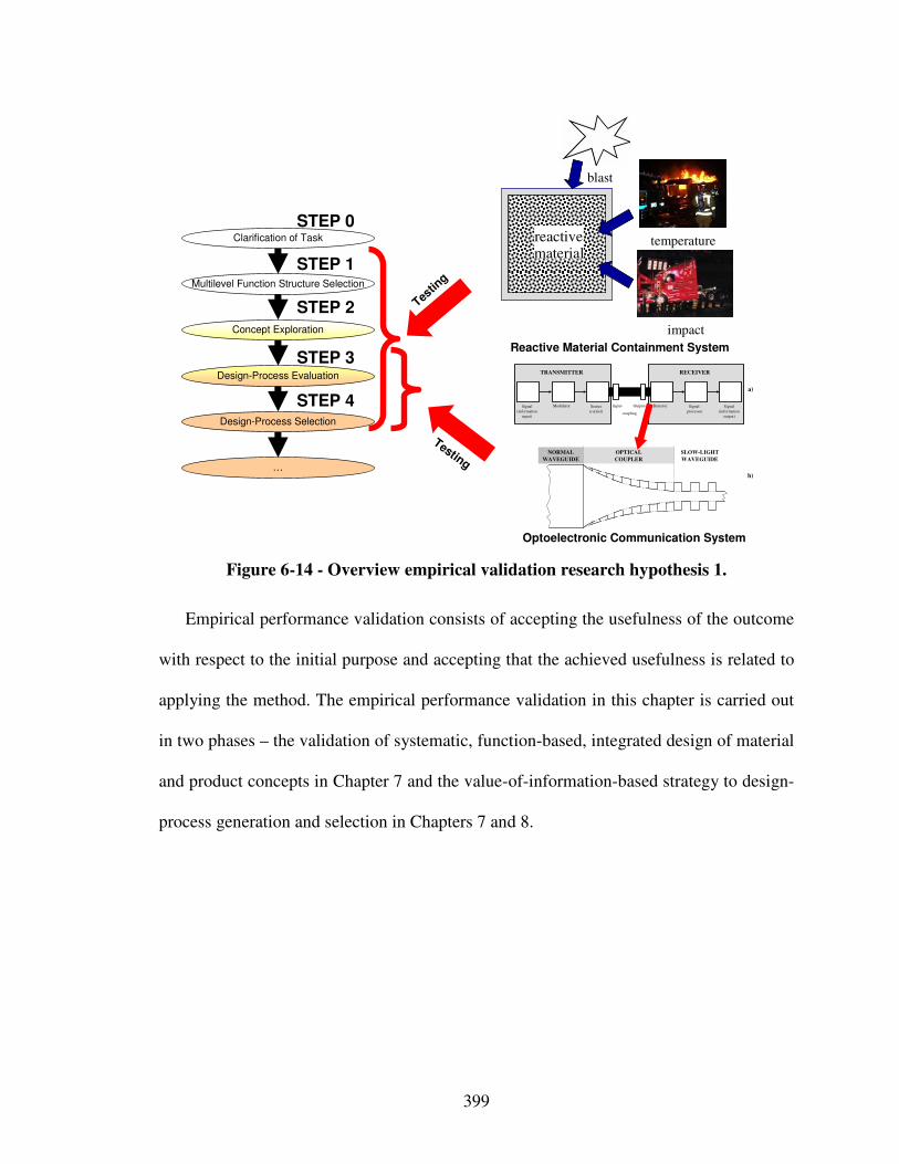
399
Reactive Material Containment System
Optoelectronic Communication System
Testin
g
Testing
Multilevel Function Structure Selection
Clarification of Task
Design-Process Evaluation
…
Design-Process Selection
Concept Exploration
temperature
impact
reactivematerial
blast
STEP 3
STEP 0
STEP 1
STEP 2
STEP 4 Signal
(information
input)
Modulator Source
(carrier)
Detector Signal-
processor
Signal
(information
output)
Input- Output-
coupling
TRANSMITTER RECEIVER
a)
b)
NORMAL
WAVEGUIDE
OPTICAL
COUPLER
SLOW-LIGHT
WAVEGUIDE
Figure 6-14 - Overview empirical validation research hypothesis 1.
Empirical performance validation consists of accepting the usefulness of the outcome
with respect to the initial purpose and accepting that the achieved usefulness is related to
applying the method. The empirical performance validation in this chapter is carried out
in two phases – the validation of systematic, function-based, integrated design of material
and product concepts in Chapter 7 and the value-of-information-based strategy to design-
process generation and selection in Chapters 7 and 8.
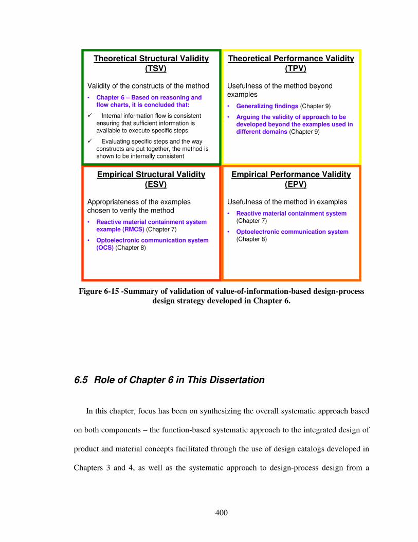
400
Empirical Structural Validity (ESV)
Appropriateness of the exampleschosen to verify the method
• Reactive material containment system example (RMCS) (Chapter 7)
• Optoelectronic communication system (OCS) (Chapter 8)
Theoretical Performance Validity (TPV)
Usefulness of the method beyondexamples
• Generalizing findings (Chapter 9)
• Arguing the validity of approach to be developed beyond the examples used in different domains (Chapter 9)
Theoretical Structural Validity (TSV)
Validity of the constructs of the method
• Chapter 6 – Based on reasoning and flow charts, it is concluded that:
� Internal information flow is consistent
ensuring that sufficient information is available to execute specific steps
� Evaluating specific steps and the way
constructs are put together, the method is shown to be internally consistent
Empirical Performance Validity (EPV)
Usefulness of the method in examples
• Reactive material containment system (Chapter 7)
• Optoelectronic communication system (Chapter 8)
Figure 6-15 -Summary of validation of value-of-information-based design-process
design strategy developed in Chapter 6.
6.5 Role of Chapter 6 in This Dissertation
In this chapter, focus has been on synthesizing the overall systematic approach based
on both components – the function-based systematic approach to the integrated design of
product and material concepts facilitated through the use of design catalogs developed in
Chapters 3 and 4, as well as the systematic approach to design-process design from a
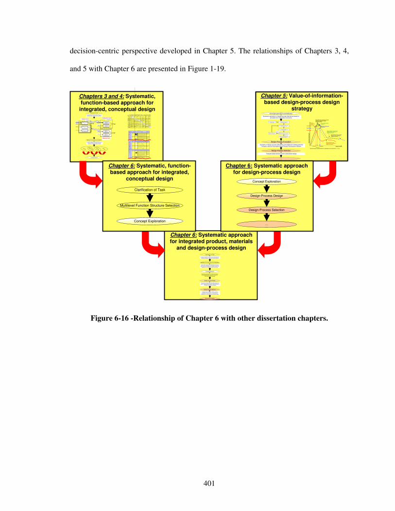
401
decision-centric perspective developed in Chapter 5. The relationships of Chapters 3, 4,
and 5 with Chapter 6 are presented in Figure 1-19.
Chapter 5: Value-of-information-
based design-process design strategy
Chapter 5: Value-of-information-based design-process design
strategy
Chapter 6: Systematic approach for integrated product, materials
and design-process design
Chapters 3 and 4: Systematic, function-based approach for
integrated, conceptual design
Systematic mapping of classified phenomena and
solution principles from multiple scales and
disciplines to multilevel function structures
Creating multilevel function structures based on
functional analysis, abstraction and synthesis
Ex,in
M x,in
Ex,in
System boundary
System function x Exyz,ou t
System function z
System function y
Ey,in
Sz,i n
M x,in Sub-system function xx
Ex,out
Sub-system function xy
Sz,i n
Ey,i n Material function yx
Eyz,out
Material function zx
Sub-system boundarySystem level
Sub-system level
Material level
Clarification of Task
Multilevel Function Structure Selection
Concept Selection
Concept
Principle
Phenomenon
Function
Pheno-
menonScale Properties Applications
" Monolithic" materials
- Metals Compared to al l other c las ses of material , metals are sti ff, s trong and tough, but
they are heavy . They have relativ ely high m el ting points . Only one metal - gold - is
chemic al ly s table as a metal. M etals are ducti le, al low ing them to be s haped by
roll ing, forging, drawingn and extrusion. They are easy to mac hine w ith prec is ion,
and they c an be joined in many different ways . Iron and nic kel are trans itional
metals inv olv ing both m etal l ic and covalent bonds, and tend to be less duc tile than
other metals . How ev er, m etals c onduct elec tric ity w el l , reflec t light and are com pletely opaque. Prim ary production of m etals is ener gy intens iv e. M any
require at least twice as m uc h ener gy per uni t weight than c om m odity polym ers.
But, m etals c an general ly be rec yc led and the energy required to do so is muc h
les s than that requried for prim ary production. Som e are tox ic, others are so inert
that they c an be im planted in the hum an body .
- Aluminum -, copper-,
m agnesium-, nick el-, steel-,
ti tanium-, zinc-al loy s
- Carbon-, s tainles-, …
s teels
- Am orphous metals , …
Ela
sti
c/in
elas
tic
def
orm
atio
n (
ten
sion
, c
ompr
ess
ion
, b
end
ing
, sh
ear
, to
rsio
n, b
uck
lin
g, f
rac
ture
, cu
ttin
g, i
nve
rsio
n,
ext
rus
ion
,
Characteristics
Solution Pr inciple
- Poly mers
From a m ac rosc ale, m onol ithic m aterials are referred to as m atter, i .e., the s ubs tanc e of whic h phys ic al objec ts are c om pos ed.
Poly mers feature an imm ense range of form , color, s urfac e finis h, trans luc enc y,
trans parency , toughnes s and flexibi l ity . E as e of molding al lows shapes that in
other materials c ould only be bui l t up by ex pens iv e as sembly m ethods . Their
exc el lent workabil i ty allows the m olding of c omplex form s , al lowing c heap manufac ture of integrated com ponents that previously were made by ass embl ing
many parts . Many poly mers are cheap both to buy and shape. Mos t res is t water,
acids and alk alis wel l, though organic s olv ents attack some. Al l are l ight and many
are flex ible. Their properties change rapidly with tem perature. Ev en at room
tem perature m any creep and when c ooled they may becom e bri ttle. P olym ers
general ly are s ens i tiv e to UV radiation and to strongly oxidiz ing env ironm ents.
- Ther mosplas tic polym ers:
ABS , Cel lulose, Ionom ers,
N ylon/PA, PC, PEEK, PE,
PM M A, PO M, PP, PS, PTFE, tpPVC, tpPU,
PET/PETE/PBT
- Ther mosetting polym ers:
Epoxy , Phenol ic, Poly ester,
ts PU, tsPVC
- Elastomers : Ac ryl ic
mac hining.
Honeycomb-cor e
sandw iches
- In-plane honeyc om bs Core c ell axes of in-plane honey com b c ores are oriented paral lel to the face-
sheets . They provide potentials for dec reas ed conduc tiv ity and fluid flow w ithin
cel ls . Relative densi ties range from 0.001 to 0.3. Their dens i fic ation s train c an be
approxim ated as :
Their relativ e s ti ffness can be approximated as :
Their relativ e s trength c an be approx imated as:
- Prism atic -, square-,
c hirac al-, etc . core in-plane
honey com bs
- Out-of- plane honeyc om bs Core c ell axes of out-of-plane honeyc om b cores are oriented perpendic ular to
fac e-sheets . They provide potentials for decr eased conduc tiv ity . R elativ e dens i ties
range from 0.001 to 0.3. Their densi fic ation s train can be approxim ated as :
Their relativ e s ti ffness can be approximated as :
Their relativ e s trength c an be approx imated as:
- Hex agonal-, sqaure-, etc .
c ore put-of-plane
honey com bs
Fiber -composites
- Continuous fiber
c om pos i tes
Continuous fiber c om pos i tes are com pos ites w ith highes t s tiffness and strength.
They are made of continuous fiber s usually em bedded in a thermos etting resin.
The fibers c arry the m echanical loads while the matrix m aterial trans mits loads to
the fibers and provides duc til i ty and toughness as well as protec ting the fiber s from dam age c aused by handling or the env ir onm ent. It is the m atrix material that
l im its the serv ic e tem perature and proc ess ing condi tions. O n m es osc ales, the
properties c an be s trongly influenc ed by the c hoice of fiber and m atrix and the
way in which thes e are combined: fiber-res in ratio, fiber length, fiber orientation,
lam inate thick nes s and the presence of fiber/resin coupl ing agents to im prov e
bonding. The strength of a composi te is inc reas ed by rais ing the fiber-resin ratio,
and orienting the fiber s paral lel to the laoding direc tion. Increased lam inate thic kness leads to reduc ed c om pos i te s trength and m odulus as there is an
inc reas ed l ik elihood of entrapped voids . Env ironm ental c onditions affec t the
perform anc e of composi tes: fatigue loading, moisture and heat all
reduc e allowable strength. P olyes ters are the m os t mos t widely us ed m atrices as
they offer r easonable properties at relativ ely low cos t. The s uperior properties of
epox ies and the term perature perform anc e of polyimides can jus tify their use in certain appl ic ations, but they are ex pens iv e.
- G lass fibers [high strength
at low c os t], polym er fibers
(organic (e.g., Kevlar) or
anorganic (e.g., Nylon, Polyes ter)) [reas onable
properties at relatively low
c ost], carbon fibers [v ery high
s trength, s tiffnes s and low
densi ty]
- Strands , fi lam ents , fiber s,
y arns (twis ted s trands), rov ings (bundled strands )
- Nonwoven m attings,
w eav es , braids , kni ts , other
- Disc ontinuous fiber c om pos i tes
Poly mers r einforc ed wi th c hopped polym er, wood, glass or c arbon fibers are referred to as dis c ontinuous fiber composi tes. The longer the fiber, the m ore
effic ient is the reinforc ement at carrying the applied loads , but s horter fibers are
eas ier to proces s and henc e c heaper. Hence, fiber length and material are the
gov er ning design v ariables. However, fibrous core com pos ites feature shape
flex ibi li ty and relatively high bending s tiffness at low densi ty.
- G lass fibers, poly mer fibers (organic (e.g., Kevlar) or
anorganic (e.g., Nylon,
Polyes ter)), carbon fibers
Me
soscale
Ela
st
ic/i
ne
las
tic
de
for
ma
tio
n (
ten
sio
n,
co
mp
res
sio
n,
be
nd
ing
, s
he
ar,
to
rs
ion
, b
uc
kli
ng
, fr
ac
tur
e,
cu
ttin
g,
inv
ers
ion
, e
xtr
us
ion
, d
raw
ing
, fl
ow
)
Honeyc om b-core s andwic hes tak e their nam e from their v isual resem blance to a bee's honeyc om b. With c ontrol lable c ore dim ens ions
and topologies on m esosc ales , they freature relativ ely high sti ffnes s and yield s trength at low dens ity. Large com pr es siv e s tr ains are
achievable at nominal ly constant s tress ( before the m aterial c om pac ts), yielding a potentially high energy abs orption c apaci ty. Honey com b-c or e s andwiches hav e ac ceptable s truc tural performance at relatively low costs wi th useful c om binations of thermophy sic al and
m echanical properties. Us ual ly, they provide benefi ts wi th respect to m ultiple use.
The c ombination of poly mers or other m atrix m aterials wi th fibers has given a range of l ight materials wi th s tiffnes s and s trength
c om parable to that of m etals. Comm only , res in materials are epoxies , polyes ters and viny ls. Fibers are m uch stronger and s ti ffer than
their equivalent in bulk form bec aus e the drawing proc ess by they are m ade orients the poly mer chains along the fiber axis or reduc es the
dens i ty of defec ts.
−≈
s
Dρ
ρε 4.11
31
rels
E
Eρ≈
relys
yρ
σ
σ5.0≈
rel
sE
Eρ1≈
rel
ys
y ρσ
σ1≈
−≈
s
Dρ
ρε 4.11
OutputInput
Mec hanica lEnergy
(In )e lastic de -
formation
In erti a
…
Electrostric-
tio n
…
Magnetostri c-
ti on
…
Impa ct
…
Friction
…
Pressure
chan ge
…
Dislocation
ha rdening
…
ElectrostaticEne rgy
Electri c field
…
Interference
…
Hall -effect
…
Electrostric-
ti on
…
Ph oto stric-
ti on
…
Electrical
resistance
…
Galvanic
element
…
Ma gnetostaticEnergy
Magnetic fie ld
…
Oscill ati ng
circuit
…
Fe rro ma g-
netism
…
Ma gneto-
striction
…
Farrad ay-
effect
…
Eddy cu rre nt
…
Sound
Ene rgyPressure wa ve
…
Electrostric-
tio n
…
Magnetostri c-
ti on
…
Reflection
…
Noise da m-
ping
…
Elasticity
…
LightEne rgy
Electro mag-
netic ra diation
…
Ph oto stric-tion
…
Absorption
…
Refractio n
…
Thermolumi -
nescen ce
…
Photoeffect
…
ThermalEne rgy
Th ermal
expansion
…
The rmo electri
city
…
Curie -Weiss
law
…
Pyro-
electricity
…
Con ve ction
…
Phase trans-
formation
…
Mole cular
Energy
Exothe rmic
reaction
…
Mo lecular
dipoloe
…
Flu ores-
cence
…
Combu stio n
Con ducti vi ty
…
Adhe sion
…
LightEnergy
ThermalEnergy
Molec ularEne rgy
MechanicalEnergy
ElectrostaticEnergy
Magnetosta ticEnergy
SoundEnergy
Chapter 6: Systematic approach for design-process design
Design-Process Design
…
Design-Process Selection
Concept Exploration
Chapter 6: Systematic, function-based approach for integrated,
conceptual design
Multilevel Function Structure Selection
Clarification of Task
Concept Exploration
Template-based decision-centric concept
exploration accounting for uncertainty and
complexity of multilevel and multiscale design
Evaluation of design-process alternatives and
value of additional multiscale modeling based on Process Performance Indicator
Multilevel Function Structure Selection
Clarification of Task
Design-Process Design
Embodiment Design
Design-Process Selection
Concept Selection
Creating multilevel function structures based on
functional analysis, abstraction and synthesis
Systematic mapping of classified phenomena
and solution principles from multiple scales and
disciplines to multilevel function structures
Systematic generation of multiscale design-process alternatives based on a value-of-
information-based strategy
Evaluation of design-process alternatives and additional modeling potential through a value-of-information-based Process Performance Indicator
Systematic generation of design-process alternatives based on principles from information economics
Design-Process Evaluation
Design-Process Selection
Concept Exploration and Selection
Template-based decision-centric embodiment design
2) Select and Evaluate Simple Initia l Design Process Alternative.
4) Evalua te most truthful design process alternative available.
Step 7: Select satisficing embodiment
design process alternative.
1) Formulate Decision Using Compromise DSP.
3) Determine Decision Point by Solving
cDSP for Maximum Payoff.
High Process Per-formance Indicator
Low Process Performance Indicator
5) Evaluate Process Performance Indicator
Simple Initial Design-Process Alternative .
6) Refine Design-Process and
Repeat Steps 3 Through 5.
…
Design Variable
Exp
ecte
d O
vera
ll P
ayo
ff
Expected payoff using
design process alternative 1(global information)
Expected payoff using refined design process alternative 2
(global information)
Payoff 2
Decision 1 Decision 2
Payoff 1
Process Performance
Indicator 1
Expected payoff using most accurate
physical or simulation models(local information)
Process Performance Indicator 2
Decisions based on predicted behavior using design process alternatives 1, 2, 3, etc.
Process Performance
Indicator 3
Expected payoff using refined design process alternative 3
(global information)
Payoff 3
Decision 3
Figure 6-16 -Relationship of Chapter 6 with other dissertation chapters.
402
Chapter 7 Designing a Reactive Material Containment System
In this chapter, the systematic approach is tested as a whole using the comprehensive
example problem of a reactive material containment system. With respect to the reactive
material containment system, the example problem, fundamental modeling, material
property, and loading assumptions are clarified first. Then, the focus is on applying the
function-based systematic approach to the integrated design of product and material
concepts and concept exploration to converge to a principal solution. This principal
solution is then used to test the value-of-information Process Performance Indicator and
strategy to embodiment design-process generation and selection. Results are discussed
along with verification and validation.
7.1 Context – Validation of the Proposed Systematic Approach
The objective in this chapter is to validate the proposed systematic approach as a
whole, using a comprehensive design example, as illustrated in Figure 7-1. The objective
of validation of the proposed systematic approach is accomplished by selecting the design
of a reactive material containment system as a reasonably complex design problem that
involves design of products, multifunctional materials, and design-processes. Results
from the example presented in this chapter are used for answering research questions 1
403
and 2. The constructs of the systematic approach, associated requirements, and
hypotheses validated in this chapter are illustrated in Table 7-1.
Since designing a reactive material containment system involves deciding on both
material and product design variables, the design problem involves the integrated design
of products and materials. The decisions about the product and constituting materials are
coupled with each other because both decisions impact achievement of performance
requirements and behavior of the product-material system. Having generated a principal
solution to the complete product-material system, the focus shifts to systematically
generating and selecting a satisficing embodiment design-process alternative, in other
words designing the product-material system and associated embodiment design-
processes in an integrated fashion. Hence, in the context of the reactive material
containment system design problem, the function-based systematic approach to integrated
product, materials and design-process design developed in this work is applied as
illustrated in Figure 7-2.
With respect to the reactive material containment system, the design problem,
fundamental modeling, material property, and loading assumptions are clarified in
Section 7.2. In Section 7.3, focus is on generating and selecting concepts through
function-based analysis, abstraction, synthesis, and systematic variation. The most
promising concepts are then further explored using partially and fully instantiated
compromise DSPs in Section 7.4 to converge to a principal solution, as discussed in
Section 7.5. Finally, the value-of-information-based design-process generation and
selection strategy developed in Chapter 5 is validated using the reactive material
containment system design example in Section 7.6.
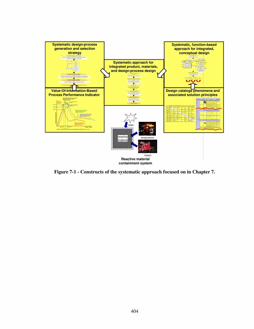
404
temperature
impact
reactivematerial
blast
Reactive material containment system
Systematic design-process generation and selection
strategy
Value-Of-Information-Based Process Performance Indicator
Systematic approach for integrated product, materials,
and design-process design
Design catalogs phenomena and associated solution principles
Systematic, function-based approach for integrated,
conceptual design
Systematic mapping of classified phenomena and
solution principles from multiple scales and
disciplines to multilevel function structures
Creating multilevel function structures based on
functional analysis, abstraction and synthesis
Ex,in
M x,in
Ex,in
System boundary
System function x Exyz,out
System function z
System function y
Ey,in
Sz,i n
M x,in Sub-system function xx
Ex,out
Sub-system function xy
Sz,in
Ey,in Material function yx
Eyz,out
Material function zx
Sub-system boundarySystem level
Sub-system level
Material level
Clarification of Task
Multilevel Function Structure Selection
Concept Selection
Concept
Principle
Phenomenon
Function
Pheno-menon
Scale Properties Applications
"Monolithic" materials
- Metals Compared to a ll other classes of material , metals are stif f, strong and tough, but
they are heavy. They have rel atively hi gh melti ng points. Only one metal - gold - is
chemically stable as a metal . Metals are d uctile, all owing them to be shaped by roll ing, forgin g, drawi ngn and extrusion. They are easy to machine with precision,
and they can be j oined i n many different ways. Iron an d nickel are transit ional
metals involving both metallic and covalent bonds, and tend to be less d uctile than
other meta ls. However, metals conduct electricity well , ref lect light a nd are
completely opaque. Pri mary producti on of metals is ene rgy i ntensive. Man y
require at least twice as much energy per un it weight than commodity polymers. But, metals can general ly be recycl ed and the energy required to do so is much
l ess than that requried for primary production. Some are toxi c, others are so inert
that they can be i mpl anted in the human body.
- Al uminum-, copper-,
magnesi um-, nickel-, steel -,
ti tanium-, zinc-al loys - Carbon-, stainles-, …
steels
- Amorphous meta ls, …
Ela
sti
c/in
ela
stic
def
orm
atio
n (
ten
sio
n,
com
pre
ssio
n,
be
nd
ing
, sh
ea
r, t
ors
ion
, bu
ck
ling
, fr
act
ure
, cu
ttin
g,
inv
ers
ion
, ex
tru
sio
n,
Characteristics
Solution Principle
- Pol ymers
From a macroscale, monolith ic materials are referred to as matter, i.e., the substance of which physi cal objects are composed.
Polymers feature an immense range of form, color, surface fini sh, transluce ncy,
transparency, toughness a nd f lexibility. Ease of moldi ng all ows sh apes that i n
other mate ri als could only be bui lt up by expensive assembly methods. Their
excellent workabili ty all ows the mol ding of complex forms, al lowing cheap
manufacture of i ntegrated components that previously were made b y assembling many parts. Many polymers are cheap both to b uy and shape. Most resist water,
acids and alkali s well, though organic so lvents attack some. All are light and ma ny
are fl exibl e. Their properties change rapidly with temperature. Even at room
temperature many creep and when cooled the y may become brit tl e. Pol ymers
generall y are sensiti ve to UV radiation and to strongly oxidi zing environments.
- Thermosplastic p olymers:
ABS, Cellulose, Ionomers,
Nyl on/PA, PC, PEEK, PE,
PMMA, POM, PP, PS, PTFE,
tpPVC, tpPU, PET/PETE/PBT
- Thermosett ing pol ymers:
Epoxy, Phenolic, Pol yester,
tsPU, tsPVC
- El astomers: Acrylic
machining.
Honeycomb-cor e
sandwiches
- In-plane honeycombs Core cel l axes of in-plane honeycomb cores are oriented paral lel to the face-
sheets. They provide potenti als for decreased conductivity and f luid f low within
cells. Relative densit ies range from 0.001 to 0.3. Their densif icatio n strain can be
approximated as:
Their relat ive st iffness can be approximated as:
Their relat ive stren gth can be ap proximated as:
- Prismati c-, square-,
chiracal-, etc. core in-plane
honeycombs
- Out-o f-plane honeycombs Core cel l axes of out-of-pl ane honeycomb cores are oriented perpendicular to
face-sheets. They provide potentials for decreased conducti vi ty. Relative densities
range from 0.001 to 0.3. Their densif ication strain can be approxi mated as:
Their relat ive st iffness can be approximated as:
Their relat ive stren gth can be ap proximated as:
- Hexagonal-, sqau re-, etc.
core put-of-plane
honeycombs
Fiber-composite s
- Conti nuous fi ber
composites
Continuous f iber composites are composi tes wi th highest st if fness and strength.
They are made of continuous fibers usuall y embedd ed in a thermosetting resin.
The f ibers carry the mechani cal loads whi le the matrix material transmits loads to the f ibers and provides ducti lity an d toughness as well as protecting the fibers
from damage caused by h andling or the environmen t. I t is the matrix material that
l imi ts the service temperature and proce ssing conditio ns. On mesoscales, the
propert ies can be strongly i nfluenced by the choice of f iber and matrix and the
way i n which these are combined: f iber-resin ratio, fi ber length, fi ber orientation,
l aminate thickness and the presence of fiber/resi n coupling agents to improve bondi ng. The strength of a composite is increased by raising the f iber-resin ratio,
and orienting the f ibers parall el to the l aoding di rection. Increased lami nate
thickness leads to reduced composite strength and modulus as there is an
i ncreased likelihood of entrapped voids. Environmental conditi ons affect the
performance of composites: fat igue l oading, moisture and heat all
reduce allowable strength. Polyesters are the most most wi dely used matri ces as they offer reasonable propertie s at relati vely low cost. The superior propert ies of
epoxies and the termperature performance of polyi mide s can justify their use in
certa in appli cations, but they are expensive.
- Glass f ibers [high strength
at low cost], polymer f ibers
(organic (e.g., Kevl ar) or anorganic (e.g., Nylon,
Polyester)) [reasonable
properties at relatively l ow
cost], carbon fibe rs [very high
strength, st if fness and low
density] - Strands, fil aments, fibers,
yarns (twisted strands),
rovi ngs (bundled strands)
- Nonwoven matt ings,
weaves, braids, knits, other
- Disco ntinuous fiber
composites
Polymers rei nforced with chopped polymer, wood, glass o r carb on f ibers are
referre d to as di scontinuous f iber composites. The longer the fi ber, the more
eff ici ent is the reinforcement at carryi ng the appli ed loads, but shorter fi bers are easier to process an d hence cheaper. Hence, f iber length and material are the
governing design variables. However, fibrous core composites fea ture shape
f lexibili ty and relati vely high bendi ng sti ffness at low densi ty.
- Glass f ibers, polymer fibers
(organic (e.g., Kevl ar) or
anorganic (e.g., Nylon, Polyester)), carbon f ibers
Me
so
sca
le
Ela
sti
c/i
ne
lasti
c d
efo
rmati
on
(te
ns
ion
, c
om
pre
ssio
n,
ben
din
g,
sh
ea
r, t
orsio
n,
buc
klin
g, fr
ac
ture,
cu
ttin
g, in
ve
rsio
n,
ex
tru
sio
n,
dra
win
g,
flo
w)
Honeycomb-core sandwiches take thei r name from their visu al resemblance to a bee's honeycomb. W ith controlla ble core di mensions
and topologies on mesoscale s, they freature relatively high stif fness and yield strength at low d ensi ty. Larg e compressive strai ns are
achievable at nominal ly constant stress (before the material compa cts), yieldi ng a potentially hi gh energy absorpti on capacity. Honeycomb-
core sandwiches have acceptabl e structural performance a t rel atively low costs with useful combinations of thermophysical and
mechani cal properti es. Usually, they provide benefits with respect to mult iple use.
The combin ation of polymers or other ma trix materi als with f ibers has gi ven a range of light materi als with st iffness and strength comparable to that of metals. Commonly, resin materi als are e poxi es, pol yesters and vinyls. Fibers are much stronger and stif fer than
thei r equivalent in bulk form because the drawing process by they are made orients the polymer ch ains along the fi ber axis or re duces the
density of defects.
−≈
s
Dρ
ρε 4.11
31rel
sE
Eρ≈
rel
ys
y ρσ
σ5.0≈
rel
sE
Eρ1≈
r el
ys
y ρσ
σ1≈
−≈
s
D ρ
ρε 4.11
Output
Input
Mechanical
Energy
(In)elastic de-
formationInertia
…
Electrostric-tion
…
Magnetostric-tion
…
Impact…
Friction…
Pressure change
…
Dislocation hardening
…
Electrostatic
Energy
Electric field
…
Interference
…
Hall-effect
…
Electrostric-
tion
…
Photostric-
tion
…
Electrical
resistance
…
Galvanic
element
…
Magnetostatic
EnergyMagnetic field…
Oscillating
circuit…
Ferromag-
netism…
Magneto-
striction…
Farraday-
effect…
Eddy current…
Sound
Energy
Pressure wave
…
Electrostric-
tion
…
Magnetostric-
tion
…
Reflection
…
Noise dam-
ping
…
Elasticity
…
Light
Energy
Electromag-
netic radiation…
Photostric-tion
…
Absorption
…
Refraction
…
Thermolumi-
nescence…
Photoeffect
…
Thermal
Energy
Thermal
expansion
…
Thermoelectri
city
…
Curie-Weiss
law
…
Pyro-
electricity
…
Convection
…
Phase trans-
formation
…
Molecular
Energy
Exothermic
reaction
…
Molecular
dipoloe
…
Fluores-
cence
…
Combustion
Conductivity
…
Adhesion
…
Light
Energy
Thermal
Energy
Molecular
Energy
Mechanical
Energy
Electrostatic
Energy
Magnetostatic
Energy
Sound
Energy
Design Variable
Ex
pe
cte
d O
ve
rall P
ayo
ff
Expected payoff usingdesign process alternative 1
(global information)
Expected payoff using refined design process alternative 2
(global information)
Payoff 2
Decision 1 Decision 2
Payoff 1
Process
Performance Indicator 1
Expected payoff using most accurate physical or simulation models
(local information)
Process Performance
Indicator 2
Decisions based on predicted behavior using design process alternatives 1, 2, 3, etc.
Process Performance
Indicator 3
Expected payoff using refined
design process alternative 3(global information)
Payoff 3
Decision 3
Template-based decision-centric concept exploration accounting for uncertainty and
complexity of multilevel and multiscale design
Evaluation of design-process alternatives and value of additional multiscale modeling based on
Process Performance Indicator
Multilevel Function Structure Selection
Clarification of Task
Design-Process Design
Embodiment Design
Design-Process Selection
Concept Selection
Creating multilevel function structures based on
functional analysis, abstraction and synthesis
Systematic mapping of classified phenomena and solution principles from multiple scales and
disciplines to multilevel function structures
Systematic generation of multiscale design-
process alternatives based on a value-of-information-based strategy
Evaluation of design-process alternatives and additional modeling potential through a value-of-information-based Process Performance Indicator
Systematic generation of design-process alternatives based on
principles from information economics
Design-Process Evaluation
Design-Process Selection
Concept Exploration and Selection
Template-based decision-centric embodiment design
2) S elect and Evaluate Simple Initial
Design Process Alte rnative.
4) Evalua te most truthful design process
alterna tive ava ilable.
Step 7: Select satisficing embodiment
design process alt ernative.
1) Formula te Decision Using
Compromi se DSP.
3) Determine Decision Point by Solving
cDSP for Maximum Payoff.
High Process Per-formance Indicator
Low Process Performance Indicator
5) Evaluate Process Perf ormance Indi catorS imple Initial Design-Process Alternative .
6) Refine Design-Process and Repeat Steps 3 Through 5.
…
Figure 7-1 - Constructs of the systematic approach focused on in Chapter 7.
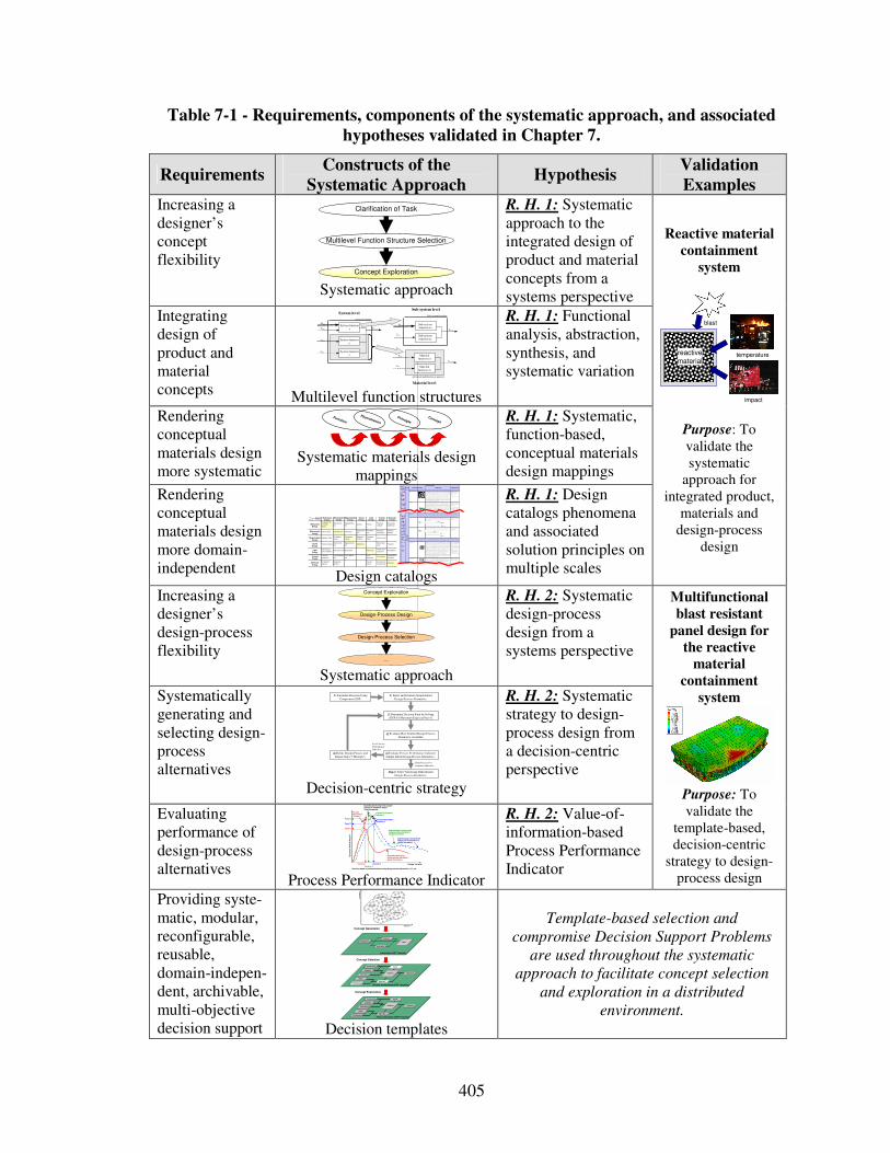
405
Table 7-1 - Requirements, components of the systematic approach, and associated
hypotheses validated in Chapter 7.
Requirements Constructs of the
Systematic Approach Hypothesis
Validation
Examples Increasing a designer’s concept flexibility
Multilevel Function Structure Selection
Clarification of Task
Concept Exploration Systematic approach
R. H. 1: Systematic approach to the integrated design of product and material concepts from a systems perspective
Integrating design of product and material concepts
Advanced mult ifunctional materia l
Ex,in
Mx,in
Ex,in
System boundary
System function x Exyz,out
System function z
System function y
Ey,in
Sz,in
Mx,in Sub-system function xx
Ex,out
Sub-system function xy
Sz,in
Ey,in Material function yx
Eyz,out
Material function zx
Sub-system boundary System level
Sub-system level
Material level Multilevel function structures
R. H. 1: Functional analysis, abstraction, synthesis, and systematic variation
Rendering conceptual materials design more systematic
Systematic materials design
mappings
R. H. 1: Systematic, function-based, conceptual materials design mappings
Rendering conceptual materials design more domain-independent
Pheno-menon
Scale Properties Applications
" M on olit hic" m ater ials
- M etals Co m pare d to al l othe r c las s es of m aterial , m etals ar e s ti ff, s tro ng and t ough, bu t
they are heav y . Th ey hav e relat iv ely high m el ting po in ts . O nly one m etal - gold - is
c hem ic al ly s table as a m etal . M etals are d uc ti le, al low in g them to be s ha ped by
rol l ing, for ging, dr awing n and e xt rus ion. T hey are eas y to m a c hine w i th prec is ion,
and the y c a n be joined in m any di ffe rent w ay s . Ir on and n ic k e l are tr ans i tional
m etals inv olv ing bo th m eta ll ic and c ov alent bon ds , and te nd to be les s duc ti le than
other m etals . H ow ev er, m etals c ond uc t elec tric i ty w el l , reflec t l ight and ar e
c om pletely opa que. P rim ar y produ c tio n of m etals is energ y int ens iv e. M any
requir e at leas t tw ic e as m uc h ene rgy per uni t w eight than c om m o dity poly m ers .
But, m etals c an g enera lly be rec y c led and the ener gy requ ir ed to d o s o is m uc h
le s s than tha t requ ried for prim ar y produ c tion. S om e ar e tox ic , othe rs are s o inert
that the y c a n be im plan ted in the hum an body .
- A lum inum - , c oppe r-,
m agne s iu m -, nic k el- , s teel-,
ti tanium - , z in c -al loy s
- C arb on-, s ta in les - , …
s teels
- A m orp hous m e tals , …
Ela
stic
/in
ela
sti
c d
efo
rm
ati
on
(te
nsio
n, co
mp
ressio
n, b
en
din
g,
sh
ear, to
rsio
n, b
ucklin
g, fr
actu
re,
cutt
ing,
inversio
n, e
xtr
usio
n,
Characteristics
Solution Principle
- P oly m er s
Fr om a m ac ros c ale, m onol i thic m a terials are refer red to as m atte r, i .e., th e s ubs tanc e of w hic h phy s ic al objec ts a re c om pos ed.
Poly m er s featur e an im m ens e r ange o f form , c olor, s ur fac e finis h, trans luc enc y ,
trans pa renc y , toug hnes s and flex ibi li ty . E as e of m olding al low s s hap es that in
other m ater ia ls c o uld only be bui l t up by ex pens iv e as s e m bly m etho ds . The ir
ex c el lent w ork ab il i ty al low s the m olding of c om plex for m s , al low ing c heap
m anufa c ture o f integra ted c om p onents th at pre viou s ly w er e m ade by as s em bl ing
m any par ts . M any p olym ers ar e c heap both to b uy and s hap e. M os t r es is t w ater,
ac ids and alk al is w el l , thoug h orga nic s olv ents attac k s o m e. A l l are l ight a nd m an y
are flex ible. Their p roper ties c hange rapidly w i th tem p eratur e. E v en at r oom
tem per ature m any c re ep and whe n c ooled th ey m ay bec om e bri ttle. Poly m er s
gener al ly ar e s ens i tiv e to U V radiat io n and to s trongly ox idiz ing en vir onm en ts .
- T herm o s plas tic poly m ers :
AB S, Cel lulos e, Ionom e rs ,
Ny lon/ PA , PC , P EE K , PE ,
PM M A, P O M , P P , PS , P TFE ,
tpPV C , tpP U ,
PE T/P ET E/ PB T
- T herm o s etting poly m e rs :
Epo x y, P hen ol ic , P oly es ter ,
ts PU , ts P VC
- E las tom er s : Ac r yl ic
m ac hining.
H one ycom b-c ore
san dw ich es
- In -plane h oney c om bs Co re c el l ax es of in -plane h oney c om b c ores ar e orien ted par al le l t o the fa c e-
s heets . T hey prov ide potentials fo r dec r eas ed c ond uc tiv ity a nd fluid flow w i thin
c el ls . Relat iv e dens i ties ran ge fro m 0.001 to 0.3. Their d ens i fic ation s tra in c an be
appro xim ated as :
Their relativ e s ti ffne ss ca n be ap prox im at ed as :
Their relativ e s tre ngth c an be appr ox im ated as :
- P ris m atic -, s quare -,
c hirac al-, etc . c ore in -plane
honey c om bs
- O u t-of- plane hon ey co m bs Co re c el l ax es of out-of -plane h oney c om b c ores ar e orient ed per pendic ular to
fac e-s he ets . Th ey prov ide po tentials for dec rea se d c onduc tiv i ty . R elativ e den s it ie s
range from 0.001 to 0.3. T heir den s if ic a tio n s train c an be app rox im ate d as :
Their relativ e s ti ffne ss ca n be ap prox im at ed as :
Their relativ e s tre ngth c an be appr ox im ated as :
- H ex ago nal-, s qau re-, e tc .
c ore pu t-of- plane
honey c om bs
Fib er- com pos ites
- C ont in uous fiber
c om p os it es
Co ntinuous fibe r c om p os it es are c o m pos i tes w i th highe s t s ti ffnes s an d s treng th.
They ar e m ad e of c ontinu ous fiber s us ual ly em bed ded in a th erm o s etting re sin.
The f ib ers c arr y the m e c hanic al loads w hi le the m atrix m aterial tr ans m its loads to
the fiber s and pr ov ides duc ti l i ty and to ughnes s as wel l as p rotec ting the fiber s
from dam ag e c aus ed b y h andl ing or the env iro nm ent. It is the m atrix m at erial that
lim it s the s erv ic e te m per ature a nd pro c es s ing c ondi tions . O n m es os c ales , the
prope rties c an be s trongly influen c ed by the ch oic e of fiber and m atrix and the
wa y in w hic h t hes e are c om bined : fiber- res in ra tio, fiber len gth, fiber orient ation,
la m inate th ic k n es s and the pres en c e of fiber /res in c ou pl in g agents to im pro v e
bonding. The s tr ength o f a c om p os i te is inc reas ed by rais ing the fiber- res in ra tio ,
and or ie nting the f ib ers par al lel to the lao ding di rec tion . Inc rea s ed lam inate
thic k nes s leads to reduc ed c om pos i te s trength and m odulus as the re is an
in c reas ed lik el ihoo d of entr apped v oids . En vir onm en tal c ondi tions af fec t the
perfor m anc e of c om p os i tes : fatigue lo ading, m oist ure an d heat a ll
reduc e al lo wab le s trengt h. Po ly es te rs are the m o s t m os t w idely us ed m atric es as
they offer reas o nable pr operties a t relativ ely low c os t. T he s uper io r pro perties o f
epox ies and the ter m per ature p erfor m anc e o f poly im ides c an ju s tif y t heir us e in
c ertain ap pl ic a tions , but th ey are e xp ens iv e.
- G las s fiber s [high s tr ength
at low c os t], poly m e r fiber s
(org anic (e.g. , Kev lar ) or
anorg anic (e.g. , Ny lon,
Poly es ter )) [r eas ona ble
prope rties at r elativ ely low
c os t], c arb on fiber s [v ery high
s trengt h, s ti ffnes s an d low
dens i ty ]
- S trand s , fi la m ents , f ib ers ,
ya rns (t wis ted s trands ) ,
rov ings ( bundled s tr ands )
- N onw ov en m attings ,
we av es , bra id s, k ni ts , other
- D is c ontinuo us fiber
c om p os it es
Poly m er s reinfo rc ed w i th c hop ped poly m e r, w ood, g la ss or c arb on fiber s are
refer red to as dis c ontinuou s fiber c om pos i tes . T he longer the fibe r, the m ore
effic ient is the r einforc e m ent a t c arry ing t he appl ied loa ds , but s ho rter fibers ar e
eas ier to proc es s an d henc e c h eaper . He nc e, fiber length an d m ate rial are t he
gov erning des ign v ar ia bles . H ow ev er, fibr ous c ore c om pos i tes f eature s hape
flex ibi li ty and relativ ely high be nding s ti ffne s s at low dens i ty .
- G las s fiber s , poly m er fibers
(org anic (e.g. , Kev lar ) or
anorg anic (e.g. , Ny lon,
Poly es ter )), c a rbon f ib ers
Mesoscale
Ela
stic
/in
ela
stic
def
orm
atio
n (t
ensi
on
, com
pre
ssio
n, b
en
din
g, s
hear
, tor
sion
, bu
cklin
g, fr
actu
re,
cutt
ing
, in
ver
sion
, ext
rusi
on, d
raw
ing,
flo
w)
H oney c om b -c ore s a ndw ich es tak e th eir nam e from their v is ual r es em blan c e to a be e's honey c om b . W it h c ontro llab le c ore dim ens ions
and to pologies on m es os c ales , th ey freatu re re la tiv e ly high s ti ffnes s and yield st rength at low dens i ty . Lar ge c om pres s iv e s tra in s are
ac hiev able a t nom inal ly c ons ta nt s tres s ( befor e the m aterial c om pac ts ), y ielding a potential ly high e nergy ab so rption c a pac i ty . H oney c om b-
c ore sa ndw ich es hav e ac c e ptable s tru c tural pe rform anc e at relativ ely low c os ts w ith us eful c om binations of therm ophy s ic al and
m ec ha nic al prope rties . U s ual ly , they pr ov id e benef its wi th r es pec t to m ul tiple us e.
The c om bination of poly m e rs or o ther m atrix m a terials w i th fibers h as giv en a r ange o f l ig ht m ate rials w ith s ti ffnes s and s trengt h
c om pa rable to that of m etals . C om m only , res in m aterials ar e epox ies , p olye s ters and v in yls . F ibers ar e m uc h s tronge r and s tif fer tha n
their e quiv alent in bu lk f orm b ec aus e the draw ing pr oc es s by they ar e m a de orient s the poly m e r c hains alon g the fiber ax is or r educ es th e
dens i ty of d efec ts .
−≈
s
D ρρ
ε 4.11
31 r el
sE
Eρ≈
rel
ys
y ρσ
σ5.0≈
rel
sE
Eρ1≈
rel
ys
y ρσ
σ1≈
−≈
s
D ρρ
ε 4.11
Design catalogs
R. H. 1: Design catalogs phenomena and associated solution principles on multiple scales
Reactive material
containment
system
temperature
impact
reactive
material
blast
Purpose: To validate the systematic
approach for integrated product,
materials and design-process
design
Increasing a designer’s design-process flexibility
Design-Process Design
…
Design-Process Selection
Concept Exploration
Systematic approach
R. H. 2: Systematic design-process design from a systems perspective
Systematically generating and selecting design-process alternatives
2) Select and Evaluate Simple Initial
Design-Process Alternative.
4) Evaluate Most Truthful Design-Process
Alternative Available.
Step 7: Select Satisficing Embodiment
Design-Process Alternative.
1) Formulate Decision Using
Compromise DSP.
3) Determine Decision Point by Solving
cDSP for Maximum Expected Payoff.
High Process Per-
formance Indicator
Low Process
Performance
Indicator
5) Evaluate Process Performance Indicator
Simple Initial Design-Process Alternative .
6) Refine Design-Process and
Repeat Steps 3 Through 5.
Decision-centric strategy
R. H. 2: Systematic strategy to design-process design from a decision-centric perspective
Evaluating performance of design-process alternatives
Design Variable
Ex
pe
cte
d O
ve
rall
Pa
yo
ff
Expected payoff usingdesign process alternative 1(global information)
Expected payoff using refined design process alternative 2(global information)
Payoff 2
Decision 1 Decision 2
Payoff 1
Process Performance Indicator 1
Expected payoff using most accurate physical or simulation models(local information)
Process Performance Indicator 2
Decisions based on predicted behavior using design process alternatives 1, 2, 3, etc.
Process Performance Indicator 3
Expected payoff using refined design process alternative 3(global information)
Payoff 3
Decision 3 Process Performance Indicator
R. H. 2: Value-of-information-based Process Performance Indicator
Multifunctional
blast resistant
panel design for
the reactive
material
containment
system
Purpose: To validate the
template-based, decision-centric
strategy to design-process design
Providing syste-matic, modular, reconfigurable, reusable, domain-indepen-dent, archivable, multi-objective decision support
Concept Generation
Concept Selection
Concept Exploration
Alternatives Rank
Instantiated sDSP Template
Importance
Attributes
Goals
Preferences
Variables
Parameters
Constraints
Response
Objective
Analysis
Driver
Fully Instantiated cDSP Template
Goals
Preferences
Variables
Parameters
Constraints
Response
Objective
Analysis
Driver
Partially Instantiated cDSP Template
Att
rib
ute
2
Attribute 1
Concept 2
Concept 5
Concept 1 Concept 3
Concept 6
Concept 4
Decision templates
Template-based selection and
compromise Decision Support Problems
are used throughout the systematic
approach to facilitate concept selection
and exploration in a distributed
environment.
OutputInput
MechanicalEnergy
( In)elastic de-
formation
Inertia
…
Electrostric-
tion
…
Magnetostr ic-
tion
…
Im pact
…
Friction
…
Pressure
change
…
Dislocation
hardening
…
Electrostatic
EnergyElectric fie ld
…
Interference
…
Hall-effect
…
Electrostric-
tion
…
Photostr ic-
tion
…
Electrical
resistance
…
Galvanic
element
…
MagnetostaticEnergy
Magnetic field
…
Oscillating
circuit
…
Ferromag-
netism
…
Magneto-
striction
…
Farraday-
effect
…
Eddy current
…
Sound
EnergyPressure wave
…
Electrostric-
tion
…
Magnetostr ic-
tion
…
Reflection
…
Noise dam-
ping
…
Elasticity
…
LightEnergy
Electromag-
netic radiation
…
Photostric-tion
…
Absorption
…
Refraction
…
Thermolumi-
nescence
…
Photoeffect
…
ThermalEnergy
Thermal
expansion
…
Thermoelectri
city
…
Curie-Weiss
law
…
Pyro-
electricity
…
Convection
…
Phase trans-
form ation
…
Molecular
Energy
Exotherm ic
reaction
…
Molecular
dipoloe
…
Fluores-
cence
…
Combustion
Conductivity
…
Adhesion
…
LightEnergy
ThermalEnergy
MolecularEnergy
MechanicalEnergy
ElectrostaticEnergy
MagnetostaticEnergy
SoundEnergy
Concept
Principle
Phenomenon
Function
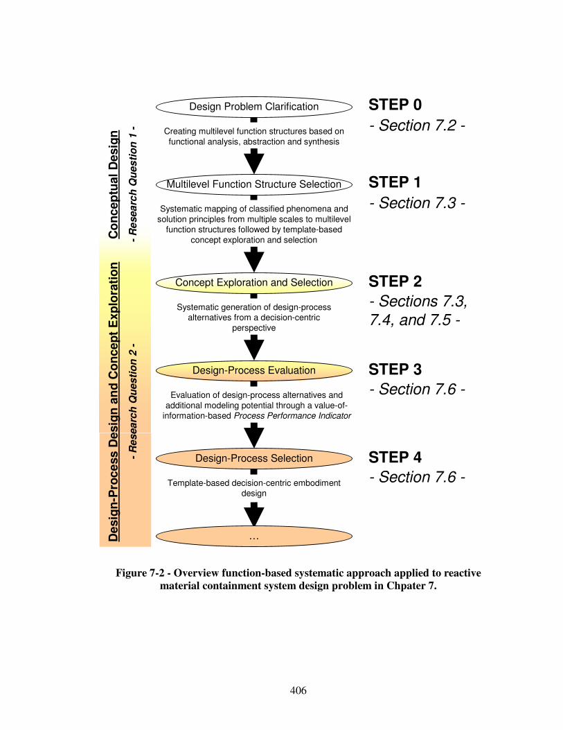
406
Template-based decision-centric embodiment design
Evaluation of design-process alternatives and
additional modeling potential through a value-of-information-based Process Performance Indicator
Multilevel Function Structure Selection
Design Problem Clarification
Design-Process Evaluation
Design-Process Selection
Concept Exploration and Selection
Co
nc
ep
tual
Desig
n
-R
esea
rch
Qu
es
tio
n 1
- Creating multilevel function structures based on
functional analysis, abstraction and synthesis
Systematic mapping of classified phenomena and
solution principles from multiple scales to multilevel function structures followed by template-based
concept exploration and selection
De
sig
n-P
roc
ess D
esig
n a
nd
Co
nce
pt
Exp
lora
tio
n
-R
es
ea
rch
Qu
es
tio
n 2
-
STEP 0
STEP 3
STEP 1
STEP 4
STEP 2
…
- Section 7.2 -
- Section 7.3 -
- Sections 7.3,
7.4, and 7.5 -
- Section 7.6 -
- Section 7.6 -
Systematic generation of design-process alternatives from a decision-centric
perspective
Figure 7-2 - Overview function-based systematic approach applied to reactive
material containment system design problem in Chpater 7.
407
7.2 Step 0 – Clarifying the Design Problem and Fundamental Assumptions
In this section, the reactive material containment system design problem, fundamental
modeling, material property, and loading assumptions are clarified in Sections 7.2.1,
7.2.2, 7.2.3, and 7.2.4 respectively as a part of Step 0 of the systematic approach
presented in Figure 7-2.
7.2.1 Clarification of the Integrated Design of Products, Materials, and Design-Processes Design Problem
The design of a reactive material containment system to transport exothermic reactive
materials for energetic applications, as shown in Figure 7-3 is selected as a reasonably
complex design problem that involves design of products, multifunctional materials, and
design-processes. Currently, reactive materials are transported to their destinations in
enclosures consisting of monolithic panels. Also, the more or less advanced materials of
the reactive material containment system are mostly selected from a finite set of available
materials. However, in order to minimize adverse economic and environmental effects
while ensuring safe handling at satisfactory reactivity, customers pose conflicting
requirements such as:
• minimization of reaction probability during transport,
• maximization of reaction probability during usage,
• maximization of collision resistance, and
408
• minimization of system weight.
The overall system has to be designed in order to ensure satisfactory performance,
i.e., reactivity, of the reactive material to be transported as well as its safe handling, i.e.,
protection against collisions which may cause impacts, high temperatures and blasts as
shown in Figure 7-3, while minimizing overall system weight. Thus, to solve this design
problem, functionalities (and related properties) from the chemical and mechanical
domains are required and they are coupled. Also, the reactive material containment
system involves decisions on both the system and material level.
On the system level for example, a decision has to be made on configuring the
containment system – potentially featuring various panel concepts, ranging from
monolithic to composite panels, or unreinforced to stiffened to multilayer sandwich
panels. Also, a designer is confronted with material level decisions to better achieve
performance requirements. For example, by selecting a sandwich structures to configure
the overall containment system, various microscale cellular material or truss structure
core configurations can be designed that feature increased energy dissipation per unit
mass to better sustain blasts. Also, in contrast to selecting a reactive material, reactive
metal powder mixtures can be designed on multiple scales. Reactive metal powder
mixtures feature reactivity and strength that can be combined with the containment
system strength or in its extreme makes a containment system obsolete. However, by for
example, designing reactive metal powder mixtures concurrently with the containment
system, reactivity and level of blast protection can be customized and hence increase a
designer’s concept flexibility.
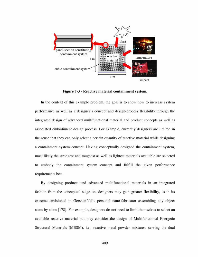
409
temperature
impact
reactive
material
blast
cubic containment system
panel-section constituting
containment system
1 m
1 m
Figure 7-3 - Reactive material containment system.
In the context of this example problem, the goal is to show how to increase system
performance as well as a designer’s concept and design-process flexibility through the
integrated design of advanced multifunctional material and product concepts as well as
associated embodiment design process. For example, currently designers are limited in
the sense that they can only select a certain quantity of reactive material while designing
a containment system concept. Having conceptually designed the containment system,
most likely the strongest and toughest as well as lightest materials available are selected
to embody the containment system concept and fulfill the given performance
requirements best.
By designing products and advanced multifunctional materials in an integrated
fashion from the conceptual stage on, designers may gain greater flexibility, as in its
extreme envisioned in Gershenfeld’s personal nano-fabricator assembling any object
atom by atom [178]. For example, designers do not need to limit themselves to select an
available reactive material but may consider the design of Multifunctional Energetic
Structural Materials (MESM), i.e., reactive metal powder mixtures, serving the dual
410
purpose of providing both energy storage and strength to a reactive system. Furthermore,
designers can consider the design of multifunctional panels that compromise the
containment system, providing the functions of both strength and increased energy
absorption per unit mass. But, designing and exploring product and material concepts in
an integrated fashion, a satisficing embodiment design-process alternative should be
identified for rapid concept exploration during the embodiment design phase.
The focus in this chapter is on
i) systematically generating system concepts, based on leveraging phenomena and
associated governing solution principles on multiple levels and scales for the
integrated design of product and material concepts in order to increase a
designer’s concept flexibility, as well as
ii) systematically generating and selecting a satisficing design-process alternative in
order to increase a designer’s design-process flexibility,
in the context of designing a reactive material containment system. In the following,
resistance against impacts and solid fragments of varying size and velocity is not
specifically considered. Only blast resistance is considered. In this work, the focus is on
designing a reactive material containment system at minimum weight to sustain blasts by
integrating protective measures or designing multifunctional materials to sustain blasts at
satisfactory reactivity. Evaluation of system concepts is driven by system performance
taking feasibility into account. Specific performance requirements and constraints have
been clarified and summarized in the requirements list shown in Table 7-2, where D
stands for demands, and W for wishes, as proposed by Pahl and Beitz [470]. Thus, the
solution neutral problem statement is:
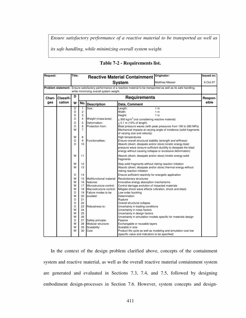
411
Ensure satisfactory performance of a reactive material to be transported as well as
its safe handling, while minimizing overall system weight.
Table 7-2 - Requirements list.
Originator: Issued on:
Matthias Messer 6-Oct-07
D 1 Length: 1 m
D 2 Width: 1 m
D 3 Height: 1 m
D 4 Weight (mass/area):
D 5 Deformation:
D 6
W 7
W 8
D 9
D 10
W 11
W 12
W 13
D 14
W 15
W 16
W 17 Microstructure control:
W 18 Macrostructure control:
D 19
W 20
D 21
D 22
D 23
W 24
W 25
W 26
D 27 Safety principle:
W 28 Modular structure:
W 29 Scalability:
W 30 Cost
Multifunctional material
features:
Absorb (divert, dissipate and/or store) kinetic energy solid
fragments
Functionalities:
Absorb (divert, dissipate and/or store) thermal energy without
risking reaction initiation
Ensure sufficient reactivity for energetic application
Revolutionary structures
Innovative energy absorption mechanisms
Ensure overall structural stability (strength and stiffness)
Robustness to: Uncertainty in loading conditions
Uncertainty in noise factors
Uncertainty in design factors
Uncertainty in simulation models specific for materials design
Product life cycle as well as modeling and simulation cost low
(specific value and indicators to be specified)
Failure modes to be
avoided:
Overall structural collapse
Rupture
Delamination
Low-order buckling
Passive
Scalable in size
Size:
Blast pressure waves (with peak pressures from 190 to 280 MPa)
Mechanical impacts at varying angle of incidence (solid fragments
of varying size and velocity)
Mitigate shock wave effects (vibration, shock and blast)
Protection from:
Absorb (divert, dissipate and/or store) kinetic energy blast
pressure wave (ensure sufficient ductility to dissipate the blast
energy without causing collapse or excessive deformation)
Stop solid fragments without risking reaction initiation
Exchangable or reusable layers
Classifi-
cation
Respon-
sibleData, CommentW No. Description
< 0.1 m (10% of length)
High temperatures
< 900 kg/m2 (not considering reactive material)
Control damage evolution of impacted materials
Chan-
ges
D Requirements
Problem statement: Ensure satisfactory performance of a reactive material to be transported as well as its safe handling,
while minimizing overall system weight.
Request: Title: Reactive Material Containment
System
In the context of the design problem clarified above, concepts of the containment
system and reactive material, as well as the overall reactive material containment system
are generated and evaluated in Sections 7.3, 7.4, and 7.5, followed by designing
embodiment design-processes in Section 7.6. However, system concepts and design-
412
process alternatives are modeled and evaluated under simplifying assumptions as
described in the following section.
7.2.2 Fundamental Modeling Assumptions
To accurately predict blast-effects, first principle calculations must be solved. In
addition, constitutive equations are needed. If these equations are solved accurately with
suitable mathematical models, they should predict the blast loads and structural response.
However, there are several barriers to predicting accurately the effects of an explosion
through the use of first-principle calculations, such as:
• In the calculation of blast due to explosions in air, the response of the air often
involves complicated phenomena, such as dust-air mixtures, boundary effects and
turbulence. Turbulent flow, for example, cannot be calculated without the
addition of models governed by empirical parameters.
• Calculation of the pressures imparted by a detonating explosive on the structure
involves complicated multiscale phenomena, which also occur in the structure
during failure.
• In the calculation of structural failure, the behavior of the materials is neither well
understood nor readily characterized in accurate constitutive equations,
particularly in fracture or fragmentation.
Also, computational efforts applied in the evaluation of explosive effects should
cover two physical disciplines:

413
• Computational fluid dynamics, which is used for the prediction of the air blast
caused by the explosion and the pressures applied to surfaces exposed to the
propagating air blast, and
• Computational solid mechanics, which deals with the prediction of the response
of structures to loads.
Furthermore, the pressures and the response of the structure are interrelated. In many
cases coupled analysis of the fluid and structures (where the fluid solution is obtained
interactively with the structural solution) is required. By accounting for the motion of the
structure while the blast calculation proceeds, the pressures that arise due to motion and
failure of the structure can be predicted more accurately than in an uncoupled calculation.
Approximations and simplifying assumptions have been made. In this work however,
nonlinear analyses are conducted in an uncoupled fashion, considering solid mechanics
only and neglecting side-effects of explosions. However, in the context of identifying and
exploring concepts for the design problem at hand, the levels of abstraction and modeling
detail are appropriate for the early stages of design and the same for all concepts and
embodiment design-process alternatives generated and evaluated. Therefore, this work is
useful in the context of generating and evaluating system concepts and embodiment
design-process alternatives.
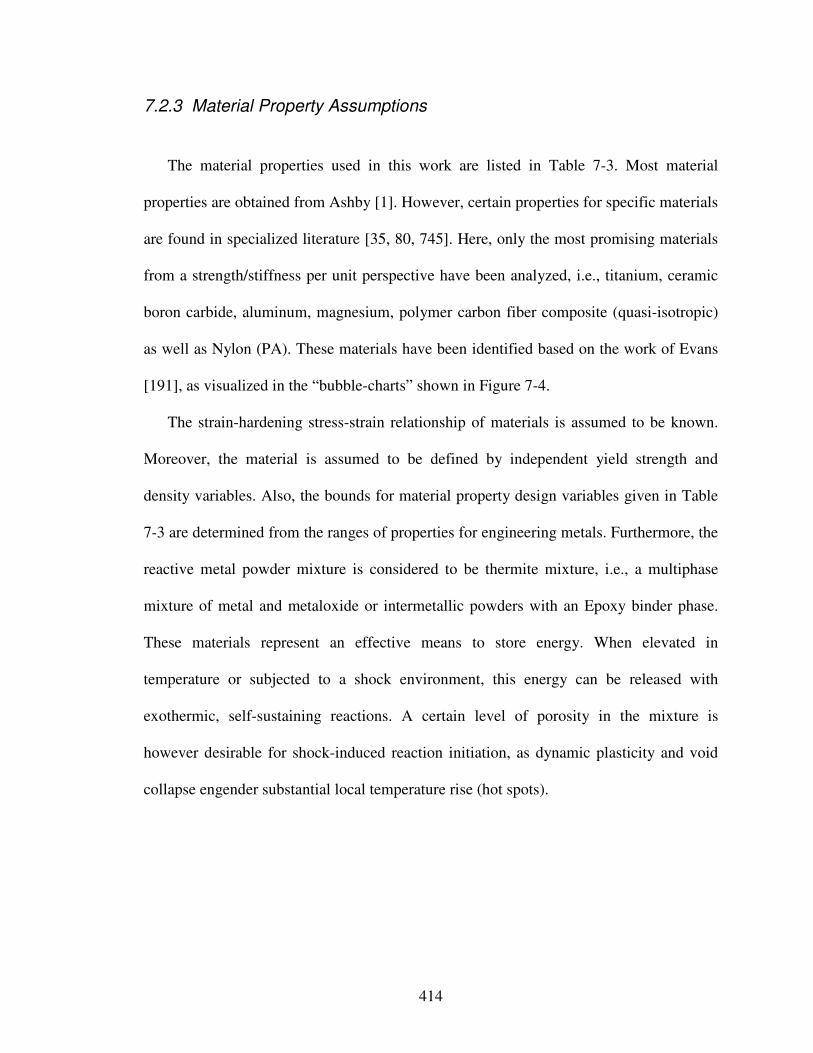
414
7.2.3 Material Property Assumptions
The material properties used in this work are listed in Table 7-3. Most material
properties are obtained from Ashby [1]. However, certain properties for specific materials
are found in specialized literature [35, 80, 745]. Here, only the most promising materials
from a strength/stiffness per unit perspective have been analyzed, i.e., titanium, ceramic
boron carbide, aluminum, magnesium, polymer carbon fiber composite (quasi-isotropic)
as well as Nylon (PA). These materials have been identified based on the work of Evans
[191], as visualized in the “bubble-charts” shown in Figure 7-4.
The strain-hardening stress-strain relationship of materials is assumed to be known.
Moreover, the material is assumed to be defined by independent yield strength and
density variables. Also, the bounds for material property design variables given in Table
7-3 are determined from the ranges of properties for engineering metals. Furthermore, the
reactive metal powder mixture is considered to be thermite mixture, i.e., a multiphase
mixture of metal and metaloxide or intermetallic powders with an Epoxy binder phase.
These materials represent an effective means to store energy. When elevated in
temperature or subjected to a shock environment, this energy can be released with
exothermic, self-sustaining reactions. A certain level of porosity in the mixture is
however desirable for shock-induced reaction initiation, as dynamic plasticity and void
collapse engender substantial local temperature rise (hot spots).
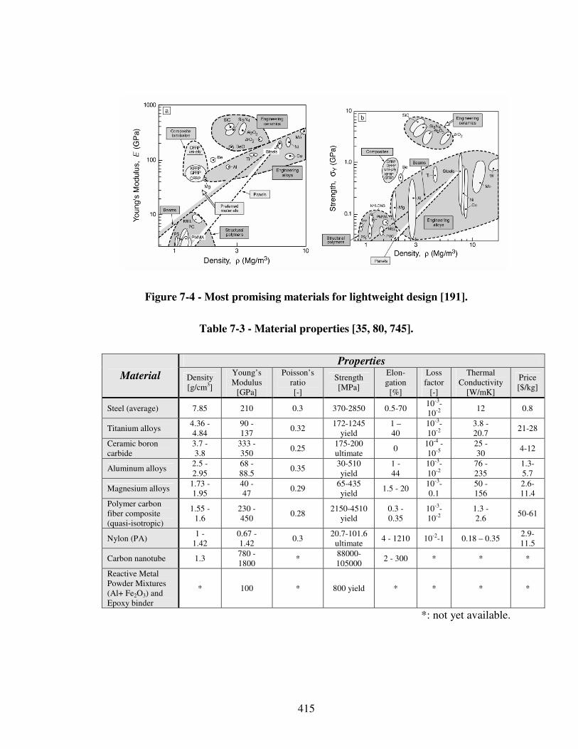
415
Figure 7-4 - Most promising materials for lightweight design [191].
Table 7-3 - Material properties [35, 80, 745].
Properties
Material Density [g/cm3]
Young’s Modulus
[GPa]
Poisson’s ratio [-]
Strength [MPa]
Elon-gation
[%]
Loss factor
[-]
Thermal Conductivity
[W/mK]
Price [$/kg]
Steel (average) 7.85 210 0.3 370-2850 0.5-70 10-3-10-2 12 0.8
Titanium alloys 4.36 - 4.84
90 - 137
0.32 172-1245
yield 1 – 40
10-3-10-2
3.8 - 20.7
21-28
Ceramic boron carbide
3.7 - 3.8
333 - 350
0.25 175-200 ultimate
0 10-4 - 10-5
25 - 30
4-12
Aluminum alloys 2.5 - 2.95
68 - 88.5
0.35 30-510 yield
1 - 44
10-3-10-2
76 - 235
1.3-5.7
Magnesium alloys 1.73 - 1.95
40 - 47
0.29 65-435 yield
1.5 - 20 10-3-0.1
50 - 156
2.6-11.4
Polymer carbon fiber composite (quasi-isotropic)
1.55 - 1.6
230 - 450
0.28 2150-4510
yield 0.3 - 0.35
10-3-10-2
1.3 - 2.6
50-61
Nylon (PA) 1 -
1.42 0.67 - 1.42
0.3 20.7-101.6
ultimate 4 - 1210 10-2-1 0.18 – 0.35
2.9-11.5
Carbon nanotube 1.3 780 - 1800
* 88000-105000
2 - 300 * * *
Reactive Metal Powder Mixtures (Al+ Fe2O3) and Epoxy binder
* 100 * 800 yield * * * *
*: not yet available.
416
7.2.4 Loading Assumptions
As clarified in Section 7.2.1, the focus in this work is on designing a reactive material
containment system to sustain blasts, which for example are caused by explosions
occurring in the context of collisions. In general, an explosion is a very fast chemical
reaction producing transient air pressure waves called blast waves. High explosives, i.e.,
explosives in which the speed of reaction is faster than the speed of sound in the
explosive (for example 5000 – 8000 m/s [2]), produce a shock wave. The characteristic
duration of a high-explosive detonation is measured in microseconds. For a ground-level
explosive device, the blast waves will travel away from the source in the form of a
hemispherical wavefront if there are no obstructions in its path.
The effects of an explosion are diverse. For explosions close to an object, the
pressure-driven effects occur quickly, on the order of microseconds to a few
milliseconds. The air-blast loads are commonly subdivided into (1) loading due to the
impinging shock front, its reflections, and the greatly increased hydrostatic pressure
behind the front, all commonly denoted as overpressure; and (2) the dynamic pressures
due to the particle velocity, or mass transfer, of air. When an explosion impinges on a
structural element, a shock wave is transmitted internally at high speed; for example,
dilatational waves (tension or compression) propagate at speeds of 4900 to 5800 m/s in
steel [2]). At these speeds, reflections and refractions quickly occur within the material
(within milliseconds), and, depending on the material properties, high-rate straining and
major disintegration effects can occur. For example, under extremely high shock
pressures, relatively brittle materials like ceramics tend to undergo multiple fractures
which can lead to fragmentation. In ductile materials like steels under similar conditions,
417
depending on the material properties and geometry, yielding and fracture can be
expected, especially if fabrication flaws are present, with fragmentation occurring in
some cases.
Results presented in this work are for the dynamic response to impulsive blast-type
loads. In all cases, a uniformly distributed impulse per unit area, I, is applied to the plate
at time t = 0. For solid panels, this impulse I is distributed uniformly through the
thickness as a uniform initial velocity v normal to the panel, v = I/ρh, where ρ is the
density of the panel material and h is the panel thickness. For sandwich panels, the
impulse is applied only to the front face sheet towards the blast, again as a uniform initial
velocity, v = I/ρhf, where hf is the front face sheet thickness. The rational for replacing the
pressure pulse acting on the panel by an initial impulse rests on the fact that the period of
the blast pulse is short compared to the response time of the panel – the period, t0,
characterizing the leading portion of a blast pulse is typically on the order of a tenth of a
millisecond [752].
Following early work by Taylor [662], the time variation of the free-field pressure at
any point in the fluid engulfed by the pulse starting at t0 is characterized as follows [752]:
0/
0
ttepp
−= Equation 6
where p is the pulse pressure, p0 is the peak pressure of free-field pulse, and t0 is the
characteristic time of the incident pressure pulse. Therefore, the momentum per are of the
free filed pulse becomes [752]:
000 tppdtI ∫ == Equation 7
When the pressure pulse impinges on the panel it sets the plate in motion and is partly
reflected. The time at which the panel achieves its maximum velocity coincides with the
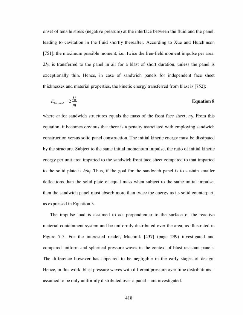
418
onset of tensile stress (negative pressure) at the interface between the fluid and the panel,
leading to cavitation in the fluid shortly thereafter. According to Xue and Hutchinson
[751], the maximum possible moment, i.e., twice the free-field moment impulse per area,
2I0, is transferred to the panel in air for a blast of short duration, unless the panel is
exceptionally thin. Hence, in case of sandwich panels for independent face sheet
thicknesses and material properties, the kinetic energy transferred from blast is [752]:
m
IE sandkin
2
0, 2= Equation 8
where m for sandwich structures equals the mass of the front face sheet, mf. From this
equation, it becomes obvious that there is a penalty associated with employing sandwich
construction versus solid panel construction. The initial kinetic energy must be dissipated
by the structure. Subject to the same initial momentum impulse, the ratio of initial kinetic
energy per unit area imparted to the sandwich front face sheet compared to that imparted
to the solid plate is h/hf. Thus, if the goal for the sandwich panel is to sustain smaller
deflections than the solid plate of equal mass when subject to the same initial impulse,
then the sandwich panel must absorb more than twice the energy as its solid counterpart,
as expressed in Equation 3.
The impulse load is assumed to act perpendicular to the surface of the reactive
material containment system and be uniformly distributed over the area, as illustrated in
Figure 7-5. For the interested reader, Muchnik [437] (page 299) investigated and
compared uniform and spherical pressure waves in the context of blast resistant panels.
The difference however has appeared to be negligible in the early stages of design.
Hence, in this work, blast pressure waves with different pressure over time distributions –
assumed to be only uniformly distributed over a panel – are investigated.
419
reactive
material
blast
cubic containment system
panel-section constituting
containment system
p(t)
Figure 7-5 - Loading reactive material containment system.
7.3 Steps 1 and 2 – Concept Generation and Selection
Based on the performance requirements clarified in Step 0 of the systematic
approach, as described in Section 7.1, concepts of the overall reactive material
containment system are designed in this section to ensure satisfactory performance, i.e,
reactivity, of the reactive material to be transported as well as its safe handling, i.e.,
protection against blast pressure waves, while minimizing overall system weight. Focus
in this section is on concept generation and selection based on the function-based
systematic approach to the integrated design of product and material concepts described
in Chapter 3, as illustrated in Figure 7-6.
In Section 7.3.1, multilevel function structures are created and selection – Step 1 of
the systematic approach – based on functional analysis, abstraction and synthesis. In
Sections 7.3.2 through 7.3.5, phenomena and associated solution principles are

420
systematically mapped to core functions identified in Section 7.3.1. Then, in Section
7.3.6 as part of Step 2 of the systematic approach, performance ranges of the most
promising solution principles are mapped in concept selection charts. In combination
with selection Decision Support Problems, the choice of solution principles for core
functions is narrowed down to the most likely to succeed solution principles. Those are
then combined into system concepts and further explored in Section 7.4 as part of Step 2
of the systematic approach.
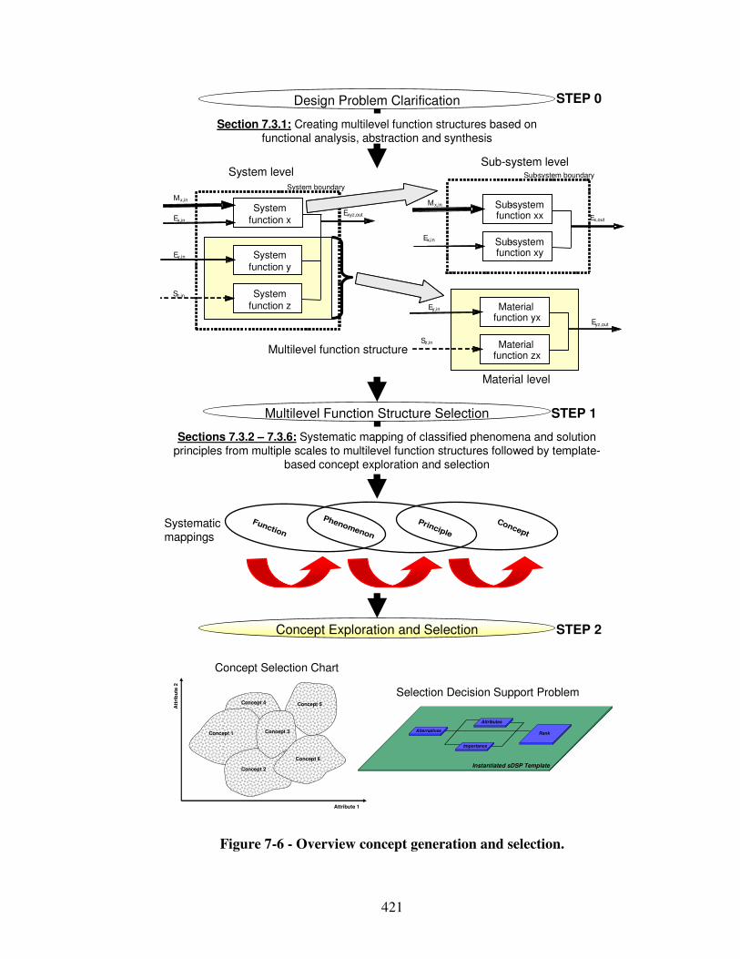
421
Sections 7.3.2 – 7.3.6: Systematic mapping of classified phenomena and solution principles from multiple scales to multilevel function structures followed by template-
based concept exploration and selection
Section 7.3.1: Creating multilevel function structures based on functional analysis, abstraction and synthesis
Ex,in
Mx,in
Ex,in
System boundary
System function x
Exyz,out
System function z
System function y
Ey,in
Sz,in
Mx,in Sub-system function xx Ex,out
Sub-system function xy
Sz,in
Ey,in Material function yx
Eyz,out
Material function zx
Sub-system boundarySystem levelSub-system level
Material level
Design Problem Clarification
Multilevel Function Structure Selection
Concept Exploration and Selection
Concept
Principle
Phenomenon
Function
STEP 0
STEP 1
STEP 2
Systematic mappings
Multilevel function structure
Att
rib
ute
2
Attribute 1
Concept 2
Concept 5
Concept 1 Concept 3
Concept 6
Concept 4
AlternativesRank
Instantiated sDSP Template
Importance
Attributes
Selection Decision Support Problem
Concept Selection Chart
Figure 7-6 - Overview concept generation and selection.
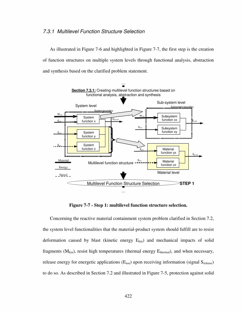
422
7.3.1 Multilevel Function Structure Selection
As illustrated in Figure 7-6 and highlighted in Figure 7-7, the first step is the creation
of function structures on multiple system levels through functional analysis, abstraction
and synthesis based on the clarified problem statement.
…
Section 7.3.1: Creating multilevel function structures based on functional analysis, abstraction and synthesis
Ex,in
Mx,in
Ex,in
System boundary
System
function xExyz,out
System function z
System
function y
Ey,in
Sz,in
Mx,in Sub-system function xx Ex,out
Sub-system function xy
Sz,in
Ey,in Material function yx
Eyz,out
Material function zx
Sub-system boundarySystem levelSub-system level
Material level
…
Multilevel Function Structure Selection STEP 1
Multilevel function structureMaterial
Energy
Signal
Figure 7-7 - Step 1: multilevel function structure selection.
Concerning the reactive material containment system problem clarified in Section 7.2,
the system level functionalities that the material-product system should fulfill are to resist
deformation caused by blast (kinetic energy Ekin) and mechanical impacts of solid
fragments (Mkin), resist high temperatures (thermal energy Ethermal), and when necessary,
release energy for energetic applications (Euse) upon receiving information (signal Srelease)
to do so. As described in Section 7.2 and illustrated in Figure 7-5, protection against solid
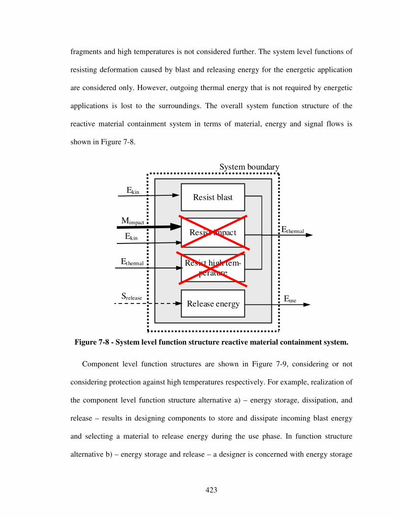
423
fragments and high temperatures is not considered further. The system level functions of
resisting deformation caused by blast and releasing energy for the energetic application
are considered only. However, outgoing thermal energy that is not required by energetic
applications is lost to the surroundings. The overall system function structure of the
reactive material containment system in terms of material, energy and signal flows is
shown in Figure 7-8.
Ekin
Mimpact
Ekin
System boundary
Resist blast
Ethermal
Release energy Euse
Resist high tem-perature
Ethermal
Srelease
Resist impact
Figure 7-8 - System level function structure reactive material containment system.
Component level function structures are shown in Figure 7-9, considering or not
considering protection against high temperatures respectively. For example, realization of
the component level function structure alternative a) – energy storage, dissipation, and
release – results in designing components to store and dissipate incoming blast energy
and selecting a material to release energy during the use phase. In function structure
alternative b) – energy storage and release – a designer is concerned with energy storage
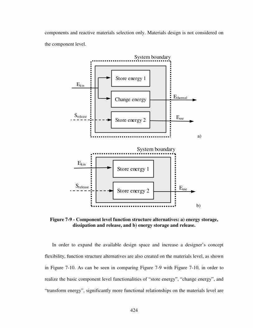
424
components and reactive materials selection only. Materials design is not considered on
the component level.
System boundary
Change energy Ethermal
Store energy 2 Euse
Srelease
Store energy 1 Ekin
a)
Ekin
System boundary
Store energy 1
Store energy 2 Euse
Srelease
b)
Figure 7-9 - Component level function structure alternatives: a) energy storage,
dissipation and release, and b) energy storage and release.
In order to expand the available design space and increase a designer’s concept
flexibility, function structure alternatives are also created on the materials level, as shown
in Figure 7-10. As can be seen in comparing Figure 7-9 with Figure 7-10, in order to
realize the basic component level functionalities of “store energy”, “change energy”, and
“transform energy”, significantly more functional relationships on the materials level are

425
required. This increase in complexity however also increases a designer’s concept
flexibility. Various function structure alternatives on the materials level are shown in
Figure 7-10.
The function structure alternative shown in Figure 7-10 a) – energy transfer, storage,
and dissipation – represents the most complex function structure alternative on the
materials level. Part of the incoming blast energy is transferred, through for example load
spreading or redirecting blast loads, as represented by the material level function
“transform energy 1”. The remainder of the incoming blast energy is transformed,
represented by the function “transform energy 2”, and then changed into internal and
finally thermal energy through for example i) a sandwich panel front face sheet
(represented by the functions change energy 1 and 2), and ii) a sandwich panel core
(represented by the function change energy 3 and 4). The part of internal energy that is
not changed into thermal energy is for example stored as internal energy Eintnal4 (strain
energy) in for example a sandwich panel back-face-sheet.
Compared to the function structure alternatives shown in Figure 7-10 a), the function
“transform energy 1” to for example spread or redirect blast loads is not considered in the
function structure alternatives illustrated in Figure 7-10 b) – energy storage, and
dissipation. Hence, Figure 7-10 b) on the materials level is consistent with Figure 7-9 a)
on the component level and Figure 7-8 on the system level. In the function structure
alternative shown in Figure 7-10 c) – energy storage, only storing incoming blast energy
in terms of strain energy and storing energy for the application in the use phase is
considered. Hence, Figure 7-10 c) on the materials level is consistent with Figure 7-9 b)
on the component level.
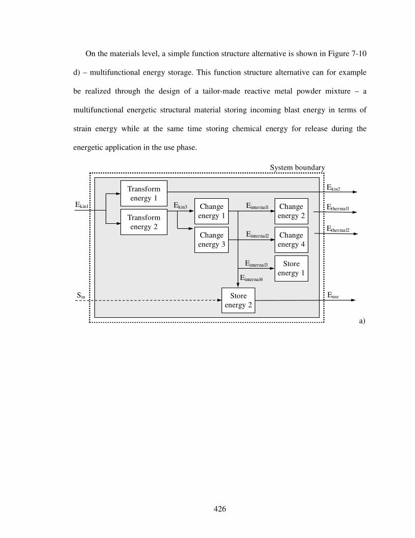
426
On the materials level, a simple function structure alternative is shown in Figure 7-10
d) – multifunctional energy storage. This function structure alternative can for example
be realized through the design of a tailor-made reactive metal powder mixture – a
multifunctional energetic structural material storing incoming blast energy in terms of
strain energy while at the same time storing chemical energy for release during the
energetic application in the use phase.
System boundary
Ekin3 Ekin1
Transform energy 1
Ekin2
Einternal4
Euse Sin
Ethermal1
Ethermal2
Einternal1
Einternal2
Transform energy 2
Change energy 2
Change energy 4
Store energy 1
Store energy 2
Change energy 1
Change energy 3
Einternal3
a)
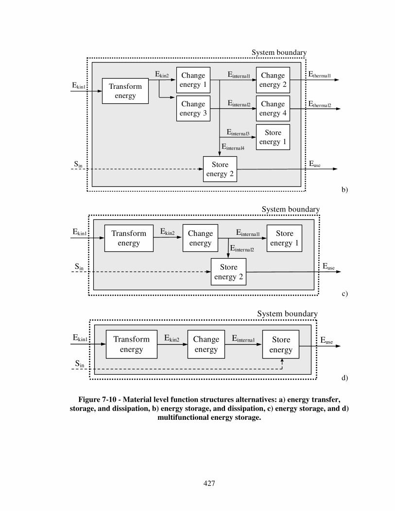
427
System boundary
Ekin2
Ekin1
Einternal4
Euse Sin
Ethermal1
Ethermal2
Einternal1
Einternal2
Transform energy
Change energy 2
Change energy 4
Store energy 1
Store energy 2
Change energy 1
Change energy 3
Einternal3
b)
System boundary
Ekin2 Ekin1
Einternal2
Euse Sin
Transform energy
Store energy 1
Store energy 2
Change energy
Einternal1
c)
System boundary
Ekin2 Ekin1 Euse
Sin
Transform energy
Store energy
Change energy
Einternal
d)
Figure 7-10 - Material level function structures alternatives: a) energy transfer,
storage, and dissipation, b) energy storage, and dissipation, c) energy storage, and d)
multifunctional energy storage.

428
On the material level, resistance against deformation is either achieved by storing
internal energy, i.e., strain energy, within system boundaries or introducing some means
of changing incoming kinetic into thermal energy, such as inelastic deformation that
dissipates incoming blast energy. Also, some incoming kinetic energy may be
transformed, in other words diverted, to resist further deformation. However, conversion
of incoming kinetic energy into internal energy of a material and dissipation at
microstructure scales might lead to reaction initiation, which is certainly not intended
during transport and handling, but may be required during energetic applications.
It is emphasized that while there are parallels between the energy balance of
thermodynamics and the function structures depicted here, it is not essential to appeal to
this principle to construct the sub-functions within the system. Nor is it necessary to
balance energy input with the sum of energy output and storage within the system.
Instead, this conceptualization is used as a syntactic tool for identifying function structure
alternatives and hence potential system concepts that may be non-intuitive or far from
conventional solution approaches even at the materials level. In the subsequent
embodiment design phase however, rigorous balance laws of energy, mass and
momentum must be employed.
For example, from a system-level perspective, as illustrated in Figure 7-8, any ready-
made containment system in conjunction with a selected reactive material results in a
system concept. On the component-level on the other hand, a designer may consider
designing parts of this containment system based on material selection approaches. In
simple terms, this involves selecting panels and/or springs of selected materials that may
only deform elastically for the containment system in addition to a specific reactive

429
material. A more enhanced concept may emerge by incorporating a functional
relationship of intentionally changing kinetic into thermal energy, as illustrated in Figure
7-9, which for example can be realized through damping components.
Considering multiscale design on the materials level, as illustrated in Figure 7-10,
concept flexibility is significantly enhanced and more advanced principal solution
alternatives may emerge. For example, a promising concept may thus be the design of a
multilayer sandwich panel, as illustrated in Figure 7-11, in which:
• a first layer changes and/or transforms incoming blast energy (such as changing
incoming blast energy into internal energy and/or transforming incoming blast
energy in order to transfer it into crumble zones or transfer local into global loads
as represented by functions transform energy 1 and 2 as well as change energy 1
and 2 in Figure 7-10 a)),
• a second layer changes kinetic energy into thermal energy, i.e., dissipates energy,
(represented through functions change energy 3 and 4 in Figure 7-10 a)), and
• a third layer changes kinetic into internal (strain) energy and stores this kind of
energy within the system (represented through function store energy 1 in Figure
7-10 a)).
The function of storing energy which may be released upon demand for its use
(represented through function store energy 2 in Figure 7-10 a)) is integral part of this
specific concept due to given performance requirements. On the materials level, it can be
realized through selecting any reactive material or the design of multifunctional energetic
structural material systems.
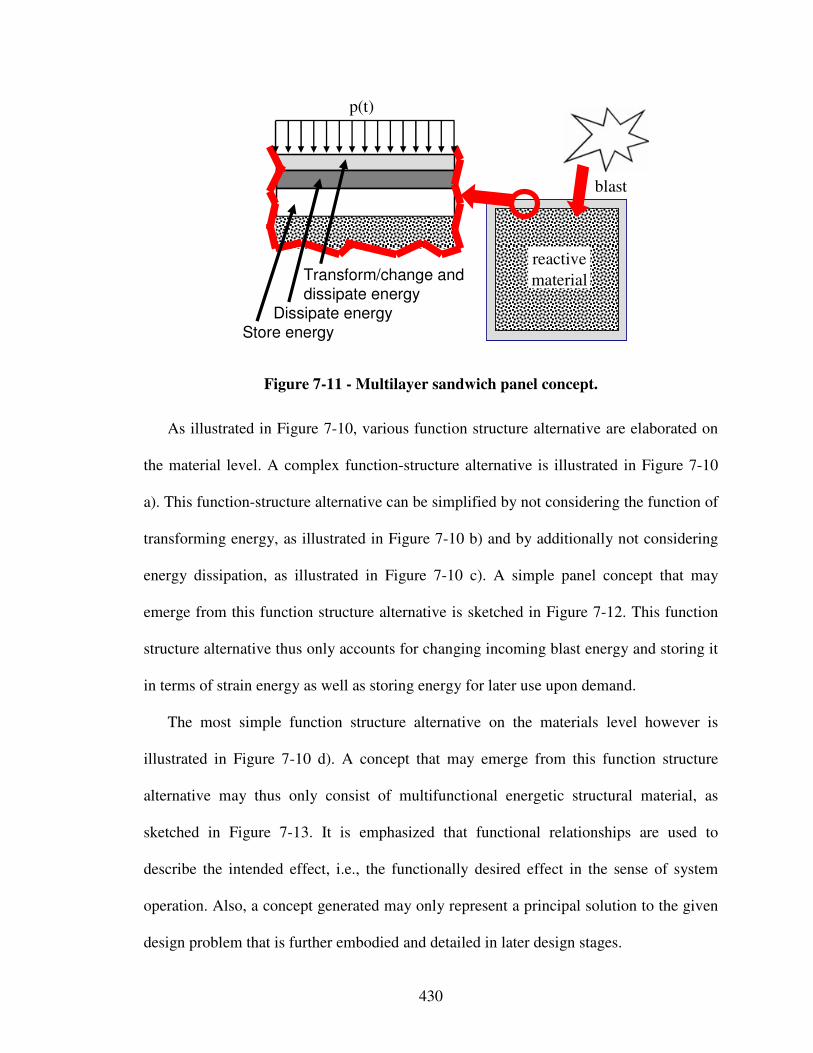
430
reactive
material
blast
p(t)
Transform/change and dissipate energy
Dissipate energyStore energy
Figure 7-11 - Multilayer sandwich panel concept.
As illustrated in Figure 7-10, various function structure alternative are elaborated on
the material level. A complex function-structure alternative is illustrated in Figure 7-10
a). This function-structure alternative can be simplified by not considering the function of
transforming energy, as illustrated in Figure 7-10 b) and by additionally not considering
energy dissipation, as illustrated in Figure 7-10 c). A simple panel concept that may
emerge from this function structure alternative is sketched in Figure 7-12. This function
structure alternative thus only accounts for changing incoming blast energy and storing it
in terms of strain energy as well as storing energy for later use upon demand.
The most simple function structure alternative on the materials level however is
illustrated in Figure 7-10 d). A concept that may emerge from this function structure
alternative may thus only consist of multifunctional energetic structural material, as
sketched in Figure 7-13. It is emphasized that functional relationships are used to
describe the intended effect, i.e., the functionally desired effect in the sense of system
operation. Also, a concept generated may only represent a principal solution to the given
design problem that is further embodied and detailed in later design stages.
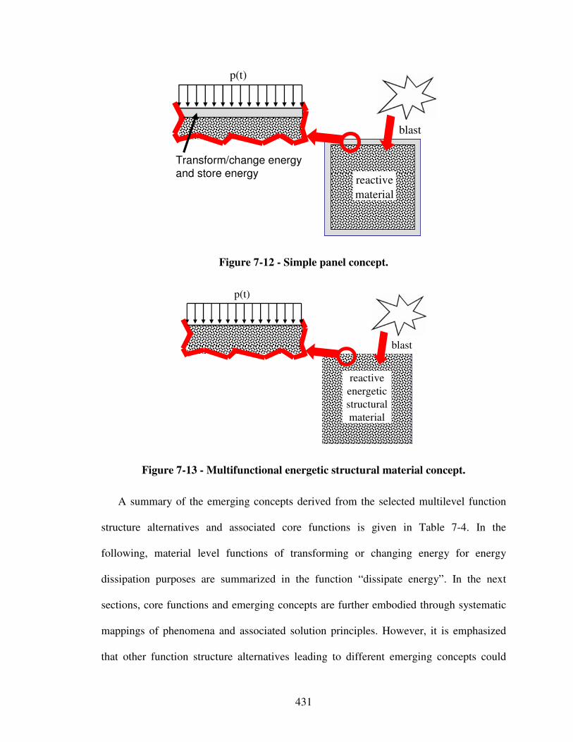
431
reactive
material
blast
p(t)
Transform/change energy and store energy
Figure 7-12 - Simple panel concept.
blast
p(t)
reactive
energetic
structural
material
Figure 7-13 - Multifunctional energetic structural material concept.
A summary of the emerging concepts derived from the selected multilevel function
structure alternatives and associated core functions is given in Table 7-4. In the
following, material level functions of transforming or changing energy for energy
dissipation purposes are summarized in the function “dissipate energy”. In the next
sections, core functions and emerging concepts are further embodied through systematic
mappings of phenomena and associated solution principles. However, it is emphasized
that other function structure alternatives leading to different emerging concepts could
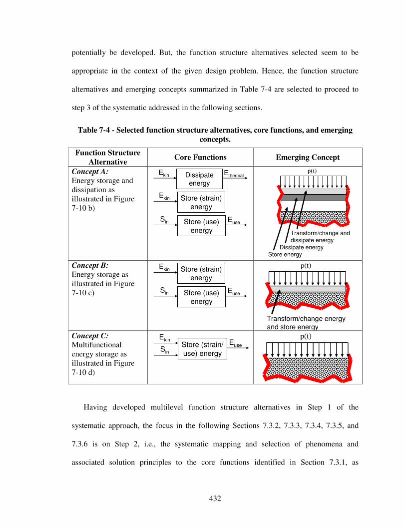
432
potentially be developed. But, the function structure alternatives selected seem to be
appropriate in the context of the given design problem. Hence, the function structure
alternatives and emerging concepts summarized in Table 7-4 are selected to proceed to
step 3 of the systematic addressed in the following sections.
Table 7-4 - Selected function structure alternatives, core functions, and emerging
concepts.
Function Structure
Alternative Core Functions Emerging Concept
Concept A: Energy storage and dissipation as illustrated in Figure 7-10 b)
Dissipate energy
Ekin Ethermal
Store (strain)
energy
Ekin
Euse
Sin Store (use)
energy
p(t)
Transform/change and
dissipate energy
Dissipate energy
Store energy
Concept B: Energy storage as illustrated in Figure 7-10 c)
Store (strain)
energy
Ekin
Euse
Sin Store (use)
energy
p(t)
Transform/change energy
and store energy Concept C: Multifunctional energy storage as illustrated in Figure 7-10 d)
EuseSin
Store (strain/
use) energy
Ekin
p(t)
Having developed multilevel function structure alternatives in Step 1 of the
systematic approach, the focus in the following Sections 7.3.2, 7.3.3, 7.3.4, 7.3.5, and
7.3.6 is on Step 2, i.e., the systematic mapping and selection of phenomena and
associated solution principles to the core functions identified in Section 7.3.1, as
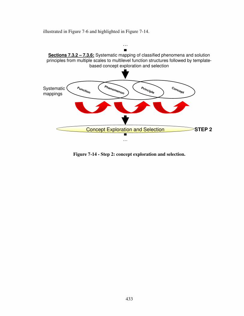
433
illustrated in Figure 7-6 and highlighted in Figure 7-14.
Sections 7.3.2 – 7.3.6: Systematic mapping of classified phenomena and solution principles from multiple scales to multilevel function structures followed by template-
based concept exploration and selection
Concept Exploration and Selection
Concept
Principle
Phenomenon
Function
STEP 2
Systematic mappings
…
…
Figure 7-14 - Step 2: concept exploration and selection.
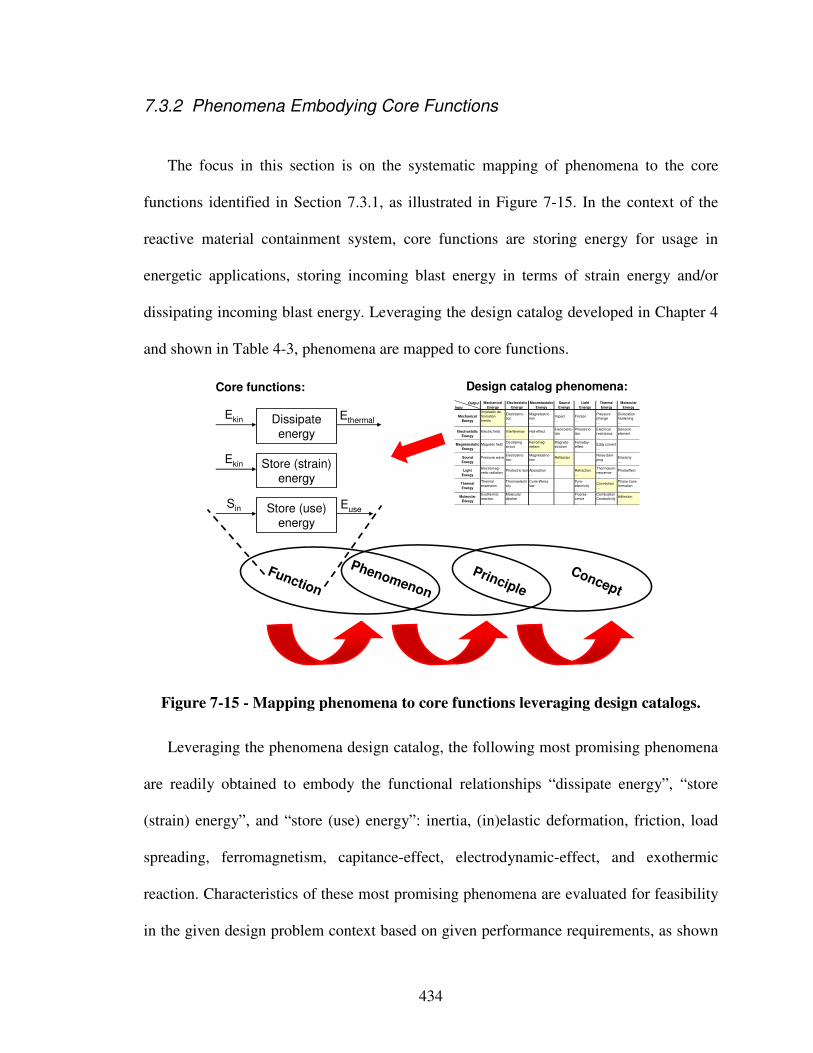
434
7.3.2 Phenomena Embodying Core Functions
The focus in this section is on the systematic mapping of phenomena to the core
functions identified in Section 7.3.1, as illustrated in Figure 7-15. In the context of the
reactive material containment system, core functions are storing energy for usage in
energetic applications, storing incoming blast energy in terms of strain energy and/or
dissipating incoming blast energy. Leveraging the design catalog developed in Chapter 4
and shown in Table 4-3, phenomena are mapped to core functions.
Concept
Principle
Phenomenon
Function
Dissipate energy
Store (strain) energy
Ekin Ethermal
Ekin
EuseSin Store (use)
energy
Core functions:Output
Input
Mechanical
Energy
(In)elastic de-
formation
Inertia
…
Electrostric-
tion
…
Magnetostric-
tion
…
Impact
…
Friction
…
Pressure
change
…
Dislocation
hardening
…
Electrostatic
Energy
Electric field
…
Interference
…
Hall-effect
…
Electrostric-
tion
…
Photostric-
tion
…
Electrical
resistance
…
Galvanic
element
…
Magnetostatic
Energy
Magnetic field
…
Oscillating
circuit
…
Ferromag-
netism
…
Magneto-
striction
…
Farraday-
effect
…
Eddy current
…
Sound
Energy
Pressure wave
…
Electrostric-
tion
…
Magnetostric-
tion
…
Reflection
…
Noise dam-
ping
…
Elasticity
…
Light
Energy
Electromag-
netic radiation
…
Photostric-tion
…
Absorption
…
Refraction
…
Thermolumi-
nescence
…
Photoeffect
…
Thermal
Energy
Thermal
expansion
…
Thermoelectri
city
…
Curie-Weiss
law
…
Pyro-
electricity
…
Convection
…
Phase trans-
formation
…
Molecular
Energy
Exothermic
reaction
…
Molecular
dipoloe
…
Fluores-
cence
…
Combustion
Conductivity
…
Adhesion
…
Light
Energy
Thermal
Energy
Molecular
Energy
Mechanical
Energy
Electrostatic
Energy
Magnetostatic
Energy
Sound
Energy
Design catalog phenomena:
Figure 7-15 - Mapping phenomena to core functions leveraging design catalogs.
Leveraging the phenomena design catalog, the following most promising phenomena
are readily obtained to embody the functional relationships “dissipate energy”, “store
(strain) energy”, and “store (use) energy”: inertia, (in)elastic deformation, friction, load
spreading, ferromagnetism, capitance-effect, electrodynamic-effect, and exothermic
reaction. Characteristics of these most promising phenomena are evaluated for feasibility
in the given design problem context based on given performance requirements, as shown

435
in Table 7-5. In order to achieve the design goals of ensuring satisfactory performance of
the reactive material to be transported as well as its safe handling while minimizing
overall system weight, criteria for preliminary selection from the design catalog are:
• anticipated overall system weight,
• anticipated system strength and stiffness, and
• anticipated reactivity.
As a result, (in)elastic deformation and exothermic reaction are selected as the most
promising and feasible phenomena to further embody the core functions identified in
Section 7.3.1.
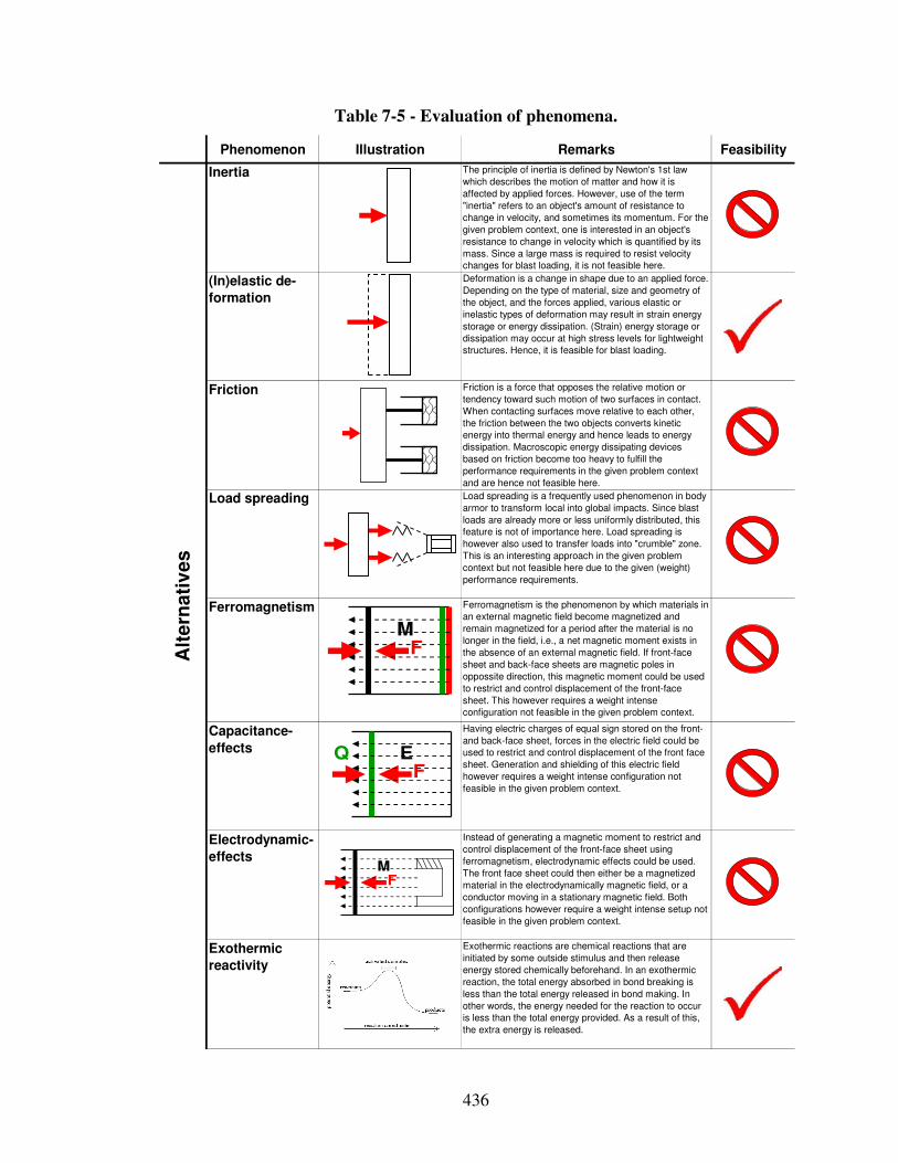
436
Table 7-5 - Evaluation of phenomena.
Phenomenon Illustration Remarks Feasibility
Inertia The principle of inertia is defined by Newton's 1st law
which describes the motion of matter and how it is
affected by applied forces. However, use of the term
"inertia" refers to an object's amount of resistance to
change in velocity, and sometimes its momentum. For the
given problem context, one is interested in an object's
resistance to change in velocity which is quantified by its
mass. Since a large mass is required to resist velocity
changes for blast loading, it is not feasible here.
(In)elastic de-
formation
Deformation is a change in shape due to an applied force.
Depending on the type of material, size and geometry of
the object, and the forces applied, various elastic or
inelastic types of deformation may result in strain energy
storage or energy dissipation. (Strain) energy storage or
dissipation may occur at high stress levels for lightweight
structures. Hence, it is feasible for blast loading.
Friction Friction is a force that opposes the relative motion or
tendency toward such motion of two surfaces in contact.
When contacting surfaces move relative to each other,
the friction between the two objects converts kinetic
energy into thermal energy and hence leads to energy
dissipation. Macroscopic energy dissipating devices
based on friction become too heavy to fulfill the
performance requirements in the given problem context
and are hence not feasible here.
Load spreading Load spreading is a frequently used phenomenon in body
armor to transform local into global impacts. Since blast
loads are already more or less uniformly distributed, this
feature is not of importance here. Load spreading is
however also used to transfer loads into "crumble" zone.
This is an interesting approach in the given problem
context but not feasible here due to the given (weight)
performance requirements.
Ferromagnetism Ferromagnetism is the phenomenon by which materials in
an external magnetic field become magnetized and
remain magnetized for a period after the material is no
longer in the field, i.e., a net magnetic moment exists in
the absence of an external magnetic field. If front-face
sheet and back-face sheets are magnetic poles in
oppossite direction, this magnetic moment could be used
to restrict and control displacement of the front-face
sheet. This however requires a weight intense
configuration not feasible in the given problem context.
Capacitance-
effects
Having electric charges of equal sign stored on the front-
and back-face sheet, forces in the electric field could be
used to restrict and control displacement of the front face
sheet. Generation and shielding of this electric field
however requires a weight intense configuration not
feasible in the given problem context.
Electrodynamic-
effects
Instead of generating a magnetic moment to restrict and
control displacement of the front-face sheet using
ferromagnetism, electrodynamic effects could be used.
The front face sheet could then either be a magnetized
material in the electrodynamically magnetic field, or a
conductor moving in a stationary magnetic field. Both
configurations however require a weight intense setup not
feasible in the given problem context.
Exothermic
reactivity
Exothermic reactions are chemical reactions that are
initiated by some outside stimulus and then release
energy stored chemically beforehand. In an exothermic
reaction, the total energy absorbed in bond breaking is
less than the total energy released in bond making. In
other words, the energy needed for the reaction to occur
is less than the total energy provided. As a result of this,
the extra energy is released.
Alt
ern
ati
ves
MF
MF
Q EF
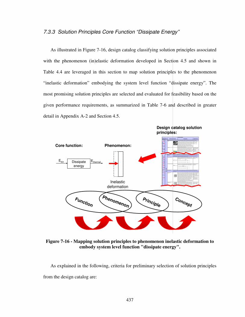
437
7.3.3 Solution Principles Core Function “Dissipate Energy”
As illustrated in Figure 7-16, design catalog classifying solution principles associated
with the phenomenon (in)elastic deformation developed in Section 4.5 and shown in
Table 4.4 are leveraged in this section to map solution principles to the phenomenon
“inelastic deformation” embodying the system level function “dissipate energy”. The
most promising solution principles are selected and evaluated for feasibility based on the
given performance requirements, as summarized in Table 7-6 and described in greater
detail in Appendix A-2 and Section 4.5.
Core function:
Concept
Principle
Phenomenon
Function
Dissipate
energy
Ekin Ethermal
Phenomenon:
Pheno-
menonScale Properties Applications
"Monolithic" materials
- Metals Compared to all other classes of material, metals are stiff, strong and tough, but
they are heavy. They have relatively high melting points. Only one metal - gold - is
chemically stable as a metal. Metals are ductile, allowing them to be shaped by
rolling, forging, drawingn and extrusion. They are easy to machine with precision,
and they can be joined in many different ways. Iron and nickel are transitional
metals involving both metallic and covalent bonds, and tend to be less ductile than
other metals. However, metals conduct electricity well, reflect light and are
completely opaque. Primary production of metals is energy intensive. Many
require at least twice as much energy per unit weight than commodity polymers.
But, metals can generally be recycled and the energy required to do so is much
less than that requried for primary production. Some are toxic, others are so inert
that they can be implanted in the human body.
- Aluminum-, copper-,
magnesium-, nickel-, steel-,
titanium-, zinc-alloys
- Carbon-, stainles-, …
steels
- Amorphous metals, …
Ela
sti
c/in
ela
sti
c d
efo
rma
tio
n (
ten
sio
n,
co
mp
ress
ion
, b
en
din
g,
sh
ear,
to
rsio
n,
bu
ckli
ng
, fr
ac
ture
, cu
ttin
g,
inve
rsio
n,
ex
tru
sio
n,
Characteristics
Solution Principle
- Polymers
From a macroscale, monolithic materials are referred to as matter, i.e., the substance of which physical objects are composed.
Polymers feature an immense range of form, color, surface finish, translucency,
transparency, toughness and flexibility. Ease of molding allows shapes that in
other materials could only be built up by expensive assembly methods. Their
excellent workability allows the molding of complex forms, allowing cheap
manufacture of integrated components that previously were made by assembling
many parts. Many polymers are cheap both to buy and shape. Most resist water,
acids and alkalis well, though organic solvents attack some. All are light and many
are flexible. Their properties change rapidly with temperature. Even at room
temperature many creep and when cooled they may become brittle. Polymers
generally are sensitive to UV radiation and to strongly oxidizing environments.
- Thermosplastic polymers:
ABS, Cellulose, Ionomers,
Nylon/PA, PC, PEEK, PE,
PMMA, POM, PP, PS, PTFE,
tpPVC, tpPU,
PET/PETE/PBT
- Thermosetting polymers:
Epoxy, Phenolic, Polyester,
tsPU, tsPVC
- Elastomers: Acrylic
general, it is a costly process of joining (precurved) face sheets and stringers or
machining.
Honeycomb-core
sandwiches
- In-plane honeycombs Core cell axes of in-plane honeycomb cores are oriented parallel to the face-
sheets. They provide potentials for decreased conductivity and fluid flow within
cells. Relative densities range from 0.001 to 0.3. Their densification strain can be
approximated as:
Their relative stiffness can be approximated as:
Their relative strength can be approximated as:
- Prismatic-, square-,
chiracal-, etc. core in-plane
honeycombs
- Out-of-plane honeycombs Core cell axes of out-of-plane honeycomb cores are oriented perpendicular to
face-sheets. They provide potentials for decreased conductivity. Relative densities
range from 0.001 to 0.3. Their densification strain can be approximated as:
Their relative stiffness can be approximated as:
Their relative strength can be approximated as:
- Hexagonal-, sqaure-, etc.
core put-of-plane
honeycombs
Fiber-composites
- Continuous fiber
composites
Continuous fiber composites are composites with highest stiffness and strength.
They are made of continuous fibers usually embedded in a thermosetting resin.
The fibers carry the mechanical loads while the matrix material transmits loads to
the fibers and provides ductility and toughness as well as protecting the fibers
from damage caused by handling or the environment. It is the matrix material that
limits the service temperature and processing conditions. On mesoscales, the
properties can be strongly influenced by the choice of fiber and matrix and the
way in which these are combined: fiber-resin ratio, fiber length, fiber orientation,
laminate thickness and the presence of fiber/resin coupling agents to improve
bonding. The strength of a composite is increased by raising the fiber-resin ratio,
and orienting the fibers parallel to the laoding direction. Increased laminate
thickness leads to reduced composite strength and modulus as there is an
increased likelihood of entrapped voids. Environmental conditions affect the
performance of composites: fatigue loading, moisture and heat all
reduce allowable strength. Polyesters are the most most widely used matrices as
they offer reasonable properties at relatively low cost. The superior properties of
epoxies and the termperature performance of polyimides can justify their use in
certain applications, but they are expensive.
- Glass fibers [high strength
at low cost], polymer fibers
(organic (e.g., Kevlar) or
anorganic (e.g., Nylon,
Polyester)) [reasonable
properties at relatively low
cost], carbon fibers [very high
strength, stiffness and low
density]
- Strands, filaments, fibers,
yarns (twisted strands),
rovings (bundled strands)
- Nonwoven mattings,
weaves, braids, knits, other
- Discontinuous fiber
composites
Polymers reinforced with chopped polymer, wood, glass or carbon fibers are
referred to as discontinuous fiber composites. The longer the fiber, the more
efficient is the reinforcement at carrying the applied loads, but shorter fibers are
easier to process and hence cheaper. Hence, fiber length and material are the
governing design variables. However, fibrous core composites feature shape
flexibility and relatively high bending stiffness at low density.
- Glass fibers, polymer fibers
(organic (e.g., Kevlar) or
anorganic (e.g., Nylon,
Polyester)), carbon fibers
Me
so
sc
ale
Ela
sti
c/i
nela
sti
c d
efo
rma
tio
n (
ten
sio
n, c
om
pre
ss
ion
, b
en
din
g,
sh
ear,
to
rsio
n, b
uc
kli
ng
, fr
actu
re,
cu
ttin
g,
inve
rsio
n, e
xtr
us
ion
, d
raw
ing
,
flo
w)
Honeycomb-core sandwiches take their name from their visual resemblance to a bee's honeycomb. With controllable core dimensions
and topologies on mesoscales, they freature relatively high stiffness and yield strength at low density. Large compressive strains are
achievable at nominally constant stress (before the material compacts), yielding a potentially high energy absorption capacity. Honeycomb-
core sandwiches have acceptable structural performance at relatively low costs with useful combinations of thermophysical and
mechanical properties. Usually, they provide benefits with respect to multiple use.
The combination of polymers or other matrix materials with fibers has given a range of light materials with stiffness and strength
comparable to that of metals. Commonly, resin materials are epoxies, polyesters and vinyls. Fibers are much stronger and stiffer than
their equivalent in bulk form because the drawing process by they are made orients the polymer chains along the fiber axis or reduces the
density of defects.
−≈
s
Dρ
ρε 4.11
31 rel
sE
Eρ≈
rel
ys
y ρσ
σ5.0≈
rel
sE
Eρ1≈
rel
ys
y ρσ
σ1≈
−≈
s
Dρ
ρε 4.11
Design catalog solution principles:
Inelastic deformation
Figure 7-16 - Mapping solution principles to phenomenon inelastic deformation to
embody system level function "dissipate energy".
As explained in the following, criteria for preliminary selection of solution principles
from the design catalog are:
438
• anticipated overall system weight,
• anticipated (plateau) dissipation stress, and
• anticipated (densification) dissipation strain.
Focus in this section is on solution principles that feature a long, flat plateau of the stress-
strain curve at near-constant load to maximize energy dissipation. In general, energy
dissipating materials have two dominant properties: the energy dissipated per unit mass,
and the stress at which this energy is dissipated [190]. The latter should be predictable
and uniform to ensure that the force transmitted remains below a critical level that upon
impact/blast might otherwise cause structural damage. The former governs the thickness
of the energy dissipating material needed to absorb the required amount of energy. In
general, the work per unit volume in deformation to a strain is simply the area under the
stress-strain curve up to the specific strain. Hence, the energy dissipated per unit volume
up to a specific strain ε is:
( )∫=ε
εεσ0
dW Equation 9
Therefore, a long, flat plateau of the stress-strain curve at near-constant load allows
large energy dissipation. Hence, high energy dissipation requires a stress-strain curve
featuring elasticity, followed by a long collapse plateau, truncated by a regime of
densification in which the stress rises steeply. Little energy is usually absorbed in the
elastic regime. Hence, if the plateau stress is almost constant, the energy absorbed per
unit volume is approximately: σε≈W . In many cases, high energy dissipation requires
the absorption of energy whilst keeping the peak force (or acceleration or deceleration)
below a certain limit (to avoid damage or injury). In other cases however, when energy
dissipation is simply to be maximized, a combination of high plateau stress and strain is

439
required. Usually, an initial buckling response is less important, from an energy point of
view, than a subsequent post-buckling (yielding) behavior, which is associated with large
strains and deflections. A more detailed review and greater selection of solution
principles associated with phenomenon inelastic deformation are given in Appendix A-2
and Section 4.5.
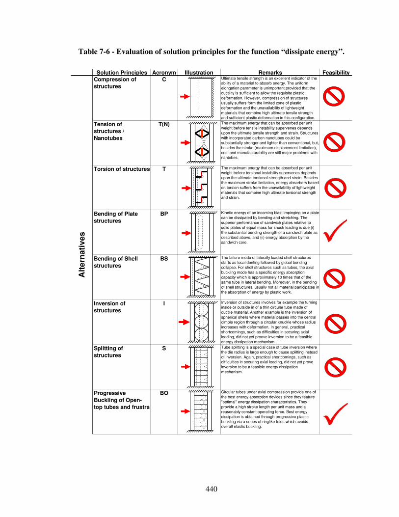
440
Table 7-6 - Evaluation of solution principles for the function “dissipate energy”.
Solution Principles Acronym Illustration Remarks FeasibilityCompression of
structures
C Ultimate tensile strength is an excellent indicator of the
ability of a material to absorb energy. The uniform
elongation parameter is unimportant provided that the
ductility is sufficient to allow the requisite plastic
deformation. However, compression of structures
usually suffers form the limited zone of plastic
deformation and the unavailability of lightweight
materials that combine high ultimate tensile strength
and sufficient plastic deformation in this configuration.
Tension of
structures /
Nanotubes
T(N) The maximum energy that can be absorbed per unit
weight before tensile instability supervenes depends
upon the ultimate tensile strength and strain. Structures
with incorporated carbon nanotubes could be
substantially stronger and lighter than conventional, but,
besides the stroke (maximum displacement limitation),
cost and manufacturability are still major problems with
nantobes.
Torsion of structures T The maximum energy that can be absorbed per unit
weight before torsional instability supervenes depends
upon the ultimate torsional strength and strain. Besides
the maximum stroke limitation, energy absorbers based
on torsion suffers from the unavailability of lightweight
materials that combine high ultimate torsional strength
and strain.
Bending of Plate
structures
BP Kinetic energy of an incoming blast impinging on a plate
can be dissipated by bending and stretching. The
superior performance of sandwich plates relative to
solid plates of equal mass for shock loading is due (i)
the substantial bending strength of a sandwich plate as
described above, and (ii) energy absorption by the
sandwich core.
Bending of Shell
structures
BS The failure mode of laterally loaded shell structures
starts as local denting followed by global bending
collapse. For shell structures such as tubes, the axial
buckling mode has a specific energy absorption
capacity which is approximately 10 times that of the
same tube in lateral bending. Moreover, in the bending
of shell structures, usually not all material participates in
the absorption of energy by plastic work.
Inversion of
structures
I Inversion of structures involves for example the turning
inside or outside in of a thin circular tube made of
ductile material. Another example is the inversion of
spherical shells where material passes into the central
dimple region through a circular knuckle whose radius
increases with deformation. In general, practical
shortcomings, such as difficulties in securing axial
loading, did not yet proove inversion to be a feasible
energy dissipation mechanism.
Splitting of
structures
S Tube splitting is a special case of tube inversion where
the die radius is large enough to cause splitting instead
of inversion. Again, practical shortcomings, such as
difficulties in securing axial loading, did not yet prove
inversion to be a feasible energy dissipation
mechanism.
Progressive
Buckling of Open-
top tubes and frustra
BO Circular tubes under axial compression provide one of
the best energy absorption devices since they feature
"optimal" energy dissipation characteristics. They
provide a high stroke length per unit mass and a
reasonably constant operating force. Best energy
dissipation is obtained through progressive plastic
buckling via a series of ringlike folds which avoids
overall elastic buckling.
Alt
ern
ati
ve
s
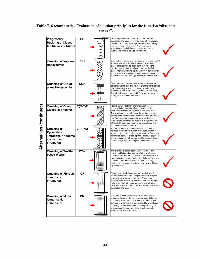
441
Table 7–6 (continued) - Evaluation of solution principles for the function “dissipate
energy”.
Progressive
Buckling of Closed-
top tubes and frustra
BC Closed-top frustra also feature "optimal" energy
dissipation characteristics. They deform by a traveling
hinge mode of deformation provided material tearing
and elastic buckling is avoided. One particular
instantiation of axially loaded closed-top tubes and
frustra is referred to as egg-box material.
Crushing of In-plane
Honeycombs
CIH Core cell axes of in-plane honeycomb cores are parallel
to the face-sheets. In-oplane honeycombs made of
elastic-plastic solids collapse plastically when the
bending moment in the cell walls reaches the fully
plastic moment, yielding a plateau both in compression
and in tension at the plastic collapse stress. Hence,
they feature "optimal" energy dissipation characteristics.
Crushing of Out-of-
plane Honeycombs
COH Core cell axes of out-of-plane honeycomb cores are
perpendicular to face-sheets. Out-of-plane honeycombs
give high energy absorption by the formation of a
succession of folds of each cell, with hoop stretching of
the cell wall between each fold. They feature "optimal"
energy dissipation characteristics.
Crushing of Open /
Closed-cell Foams
C(O/C)F Foams feature "optimal" energy dissipation
characteristics during bending-dominated collapse.
Their properties can be adjusted over a wide range.
The low densities permit the design of light and strong
components. Economies of processing and fabrication
give foams cost advantages in many applications.
Furthermore, benefits with respect to multiple use give
integrally formed metal foam cores advantages over
conventional panel structures
Crushing of
Pyramidal /
Tetragonal / Kagome
microtruss
structures
C(P/T/K) Microtruss structures feature stretching dominated
collapse (where struts support axial loads, tensile in
some, compressive in others when loaded). Stretching
dominated behavior offers "optimal" energy dissipation
characteristics as well as greater stiffness and strength
per unit weight than bending dominated behavior.
Crushing of Textile-
based Weave
CTW The crushing of textile-based weaves is based on
proven textile-based approaches to the synthesis of
periodic metal microtruss laminates consisting of wire
weaves joined using a transient liquid phase. Crushing
of textile-based weaves exhibits "optimal" energy
dissipation characteristics at relatively low weight and
high stiffness.
Crushing of Fibrous
composite
structures
CF Fibrous core sandwich panels are thin, lightweight
structures with face-sheets separated by an irregular
arrangement of independent fibers. These core
configurations provide high bending stiffness and light
weight, together with good formability and vibration
damping. However, they do not feature "optimal" energy
dissipation characteristics.
Crushing of Multi-
length-scale
composites
CM Multi-length-scale composites are isotropic cellular
materials that attain theoretical upper bounds for the
bulk and shear moduli of a voided solid. Hence, the
stiffness to weight ratio is maximized. However, those
obtaining the theoretical bounds most promising for
energy absorption are multiscale structures and
therefore not manufacturable.
Alt
ern
ati
ves
(co
nti
nu
ed
)
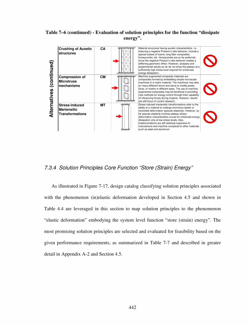
442
Table 7–6 (continued) - Evaluation of solution principles for the function “dissipate
energy”.
Crushing of Auxetic
structures
CA Material structures having auxetic characteristics, i.e.,
featuring a negative Poisson’s ratio behavior, include a
special subset of foams, long fiber composites,
honeycombs, etc. Honeycombs are so far preferred,
since the negative Poisson’s ratio behavior implies a
stiffening geometric effect. However, analyses and
experimental results so far do not show the plateau at a
sufficiently high stress level required for enhanced
energy dissipation.
Compression of
Microtruss
mechanisms
CM Machine augmented composite materials are
composites formed by embedding simple microscale
machines in a matrix material. The machines may take
on many different forms and serve to modify power,
force, or motion in different ways. The use of machine
augmented composites may be beneficial in providing
new methods for energy control through their capability
of influencing forces during impacts. However, results
are still focus of current research.
Stress-induced
Martensitic
Transformations
MT Stress induced martensitic transformations refer to the
ability of a material to undergo enormous elastic or
reversible deformation (pseudo-elasticity). However, so
far pseudo-elasticity involves plateau stress-
deformation characteristics crucial for enhanced energy
dissipation only at low stress levels. Also,
implementations are still relatively expensive to
manufacture and machine compared to other materials
such as steel and aluminum.
Alt
ern
ati
ves
(c
on
tin
ue
d)
7.3.4 Solution Principles Core Function “Store (Strain) Energy”
As illustrated in Figure 7-17, design catalog classifying solution principles associated
with the phenomenon (in)elastic deformation developed in Section 4.5 and shown in
Table 4.4 are leveraged in this section to map solution principles to the phenomenon
“elastic deformation” embodying the system level function “store (strain) energy”. The
most promising solution principles are selected and evaluated for feasibility based on the
given performance requirements, as summarized in Table 7-7 and described in greater
detail in Appendix A-2 and Section 4.5.
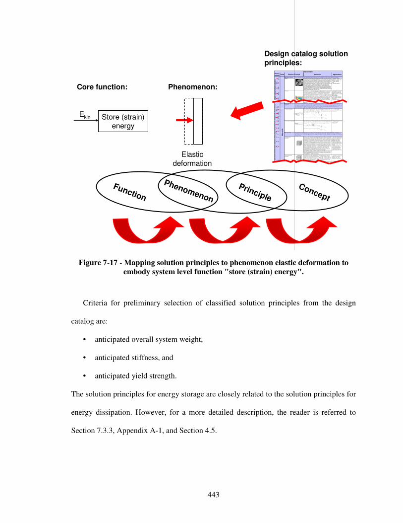
443
Core function:
Concept
Principle
Phenomenon
Function
Phenomenon:
Pheno-menon
Scale Properties Applications
"Monolithic" materials
- Metals Compared to all other classes of material, metals are stiff, strong and tough, but
they are heavy. They have relatively high melting points. Only one metal - gold - is
chemically stable as a metal. Metals are ductile, allowing them to be shaped by
rolling, forging, drawingn and extrusion. They are easy to machine with precision,
and they can be joined in many different ways. Iron and nickel are transitional
metals involving both metallic and covalent bonds, and tend to be less ductile than
other metals. However, metals conduct electricity well, reflect l ight and are
completely opaque. Primary production of metals is energy intensive. Many
require at least twice as much energy per unit weight than commodity polymers.
But, metals can generally be recycled and the energy required to do so is much less than that requried for primary production. Some are toxic, others are so inert
that they can be implanted in the human body.
- Aluminum-, copper-,
magnesium-, nickel-, steel-,
titanium-, zinc-alloys
- Carbon-, stainles-, …
steels
- Amorphous metals, …
Ela
sti
c/i
nela
sti
c d
efo
rma
tio
n (
ten
sio
n,
co
mp
ress
ion
, b
en
din
g,
sh
ear,
to
rsio
n,
bu
cklin
g, fr
actu
re, cu
ttin
g,
inve
rsio
n, e
xtr
usio
n,
Characteristics
Solution Principle
- Polymers
From a macroscale, monolithic materials are referred to as matter, i .e., the substance of which physical objects are composed.
Polymers feature an immense range of form, color, surface finish, translucency,
transparency, toughness and flexibility. Ease of molding allows shapes that in
other materials could only be built up by expensive assembly methods. Their
excellent workability allows the molding of complex forms, allowing cheap
manufacture of integrated components that previously were made by assembling
many parts. Many polymers are cheap both to buy and shape. Most resist water,
acids and alkalis well, though organic solvents attack some. All are light and many
are flexible. Their properties change rapidly with temperature. Even at room
temperature many creep and when cooled they may become brittle. Polymers
generally are sensitive to UV radiation and to strongly oxidizing environments.
- Thermosplastic polymers:
ABS, Cellulose, Ionomers,
Nylon/PA, PC, PEEK, PE,
PMMA, POM, PP, PS, PTFE,
tpPVC, tpPU,
PET/PETE/PBT
- Thermosetting polymers:
Epoxy, Phenolic, Polyester,
tsPU, tsPVC
- Elastomers: Acrylic
general, it is a costly process of joining (precurved) face sheets and stringers or
machining.
Honeycomb-core
sandwiches
- In-plane honeycombs Core cell axes of in-plane honeycomb cores are oriented parallel to the face-
sheets. They provide potentials for decreased conductivity and fluid flow within
cells. Relative densities range from 0.001 to 0.3. Their densification strain can be
approximated as:
Their relative stiffness can be approximated as:
Their relative strength can be approximated as:
- Prismatic-, square-,
chiracal-, etc. core in-plane
honeycombs
- Out-of-plane honeycombs Core cell axes of out-of-plane honeycomb cores are oriented perpendicular to
face-sheets. They provide potentials for decreased conductivity. Relative densities
range from 0.001 to 0.3. Their densification strain can be approximated as:
Their relative stiffness can be approximated as:
Their relative strength can be approximated as:
- Hexagonal-, sqaure-, etc.
core put-of-plane
honeycombs
Fiber-composites
- Continuous fiber
composites
Continuous fiber composites are composites with highest stiffness and strength.
They are made of continuous fibers usually embedded in a thermosetting resin.
The fibers carry the mechanical loads while the matrix material transmits loads to
the fibers and provides ductili ty and toughness as well as protecting the fibers
from damage caused by handling or the environment. It is the matrix material that
l imits the service temperature and processing conditions. On mesoscales, the
properties can be strongly influenced by the choice of fiber and matrix and the
way in which these are combined: fiber-resin ratio, fiber length, fiber orientation,
laminate thickness and the presence of fiber/resin coupling agents to improve
bonding. The strength of a composite is increased by raising the fiber-resin ratio,
and orienting the fibers parallel to the laoding direction. Increased laminate
thickness leads to reduced composite strength and modulus as there is an
increased likelihood of entrapped voids. Environmental conditions affect the
performance of composites: fatigue loading, moisture and heat all
reduce allowable strength. Polyesters are the most most widely used matrices as
they offer reasonable properties at relatively low cost. The superior properties of
epoxies and the termperature performance of polyimides can justify their use in
certain applications, but they are expensive.
- Glass fibers [high strength
at low cost], polymer fibers
(organic (e.g., Kevlar) or
anorganic (e.g., Nylon,
Polyester)) [reasonable
properties at relatively low
cost], carbon fibers [very high
strength, stiffness and low
density]
- Strands, filaments, fibers,
yarns (twisted strands),
rovings (bundled strands)
- Nonwoven mattings,
weaves, braids, knits, other
- Discontinuous fiber
composites
Polymers reinforced with chopped polymer, wood, glass or carbon fibers are
referred to as discontinuous fiber composites. The longer the fiber, the more
efficient is the reinforcement at carrying the applied loads, but shorter fibers are
easier to process and hence cheaper. Hence, fiber length and material are the
governing design variables. However, fibrous core composites feature shape
flexibility and relatively high bending stiffness at low density.
- Glass fibers, polymer fibers
(organic (e.g., Kevlar) or
anorganic (e.g., Nylon,
Polyester)), carbon fibers
Me
so
sc
ale
Ela
stic
/in
ela
sti
c d
efo
rmati
on
(te
nsio
n,
co
mp
ressio
n, b
end
ing
, sh
ear,
to
rsio
n,
bu
ckli
ng
, fr
actu
re, cu
ttin
g, in
vers
ion,
extr
usio
n,
dra
win
g,
flo
w)
Honeycomb-core sandwiches take their name from their visual resemblance to a bee's honeycomb. With controllable core dimensions
and topologies on mesoscales, they freature relatively high stiffness and yield strength at low density. Large compressive strains are
achievable at nominally constant stress (before the material compacts), yielding a potentially high energy absorption capacity. Honeycomb-
core sandwiches have acceptable structural performance at relatively low costs with useful combinations of thermophysical and
mechanical properties. Usually, they provide benefits with respect to multiple use.
The combination of polymers or other matrix materials with fibers has given a range of l ight materials with stiffness and strength
comparable to that of metals. Commonly, resin materials are epoxies, polyesters and vinyls. Fibers are much stronger and stiffer than
their equivalent in bulk form because the drawing process by they are made orients the polymer chains along the fiber axis or reduces the
density of defects.
−≈
s
Dρ
ρε 4.11
31 rel
sE
Eρ≈
rel
ys
y ρσ
σ5.0≈
rel
sE
Eρ1≈
rel
ys
y ρσ
σ1≈
−≈
s
D ρ
ρε 4.11
Design catalog solution principles:
Elastic
deformation
Store (strain) energy
Ekin
Figure 7-17 - Mapping solution principles to phenomenon elastic deformation to
embody system level function "store (strain) energy".
Criteria for preliminary selection of classified solution principles from the design
catalog are:
• anticipated overall system weight,
• anticipated stiffness, and
• anticipated yield strength.
The solution principles for energy storage are closely related to the solution principles for
energy dissipation. However, for a more detailed description, the reader is referred to
Section 7.3.3, Appendix A-1, and Section 4.5.
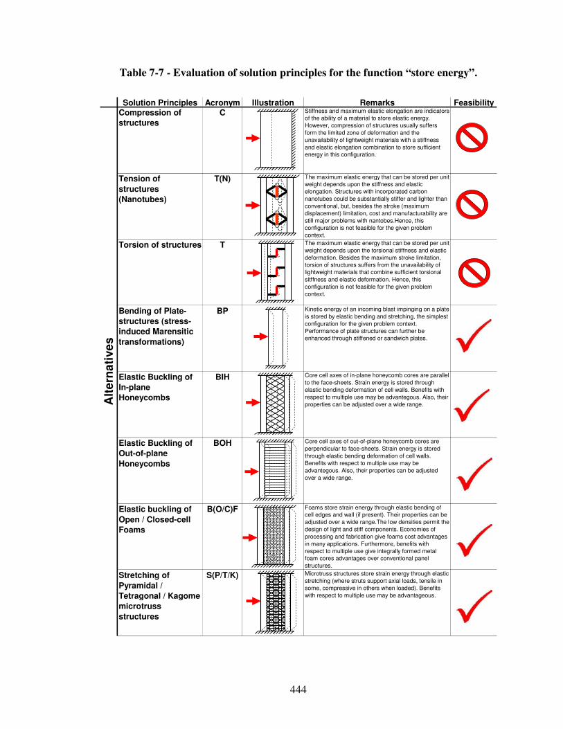
444
Table 7-7 - Evaluation of solution principles for the function “store energy”.
Solution Principles Acronym Illustration Remarks FeasibilityCompression of
structures
C Stiffness and maximum elastic elongation are indicators
of the ability of a material to store elastic energy.
However, compression of structures usually suffers
form the limited zone of deformation and the
unavailability of lightweight materials with a stiffness
and elastic elongation combination to store sufficient
energy in this configuration.
Tension of
structures
(Nanotubes)
T(N) The maximum elastic energy that can be stored per unit
weight depends upon the stiffness and elastic
elongation. Structures with incorporated carbon
nanotubes could be substantially stiffer and lighter than
conventional, but, besides the stroke (maximum
displacement) limitation, cost and manufacturability are
still major problems with nantobes.Hence, this
configuration is not feasible for the given problem
context.
Torsion of structures T The maximum elastic energy that can be stored per unit
weight depends upon the torsional stiffness and elastic
deformation. Besides the maximum stroke limitation,
torsion of structures suffers from the unavailability of
lightweight materials that combine sufficient torsional
sitffness and elastic deformation. Hence, this
configuration is not feasible for the given problem
context.
Bending of Plate-
structures (stress-
induced Marensitic
transformations)
BP Kinetic energy of an incoming blast impinging on a plate
is stored by elastic bending and stretching, the simplest
configuration for the given problem context.
Performance of plate structures can further be
enhanced through stiffened or sandwich plates.
Elastic Buckling of
In-plane
Honeycombs
BIH Core cell axes of in-plane honeycomb cores are parallel
to the face-sheets. Strain energy is stored through
elastic bending deformation of cell walls. Benefits with
respect to multiple use may be advantegous. Also, their
properties can be adjusted over a wide range.
Elastic Buckling of
Out-of-plane
Honeycombs
BOH Core cell axes of out-of-plane honeycomb cores are
perpendicular to face-sheets. Strain energy is stored
through elastic bending deformation of cell walls.
Benefits with respect to multiple use may be
advantegous. Also, their properties can be adjusted
over a wide range.
Elastic buckling of
Open / Closed-cell
Foams
B(O/C)F Foams store strain energy through elastic bending of
cell edges and wall (if present). Their properties can be
adjusted over a wide range.The low densities permit the
design of light and stiff components. Economies of
processing and fabrication give foams cost advantages
in many applications. Furthermore, benefits with
respect to multiple use give integrally formed metal
foam cores advantages over conventional panel
structures.
Stretching of
Pyramidal /
Tetragonal / Kagome
microtruss
structures
S(P/T/K) Microtruss structures store strain energy through elastic
stretching (where struts support axial loads, tensile in
some, compressive in others when loaded). Benefits
with respect to multiple use may be advantageous.
Alt
ern
ati
ve
s
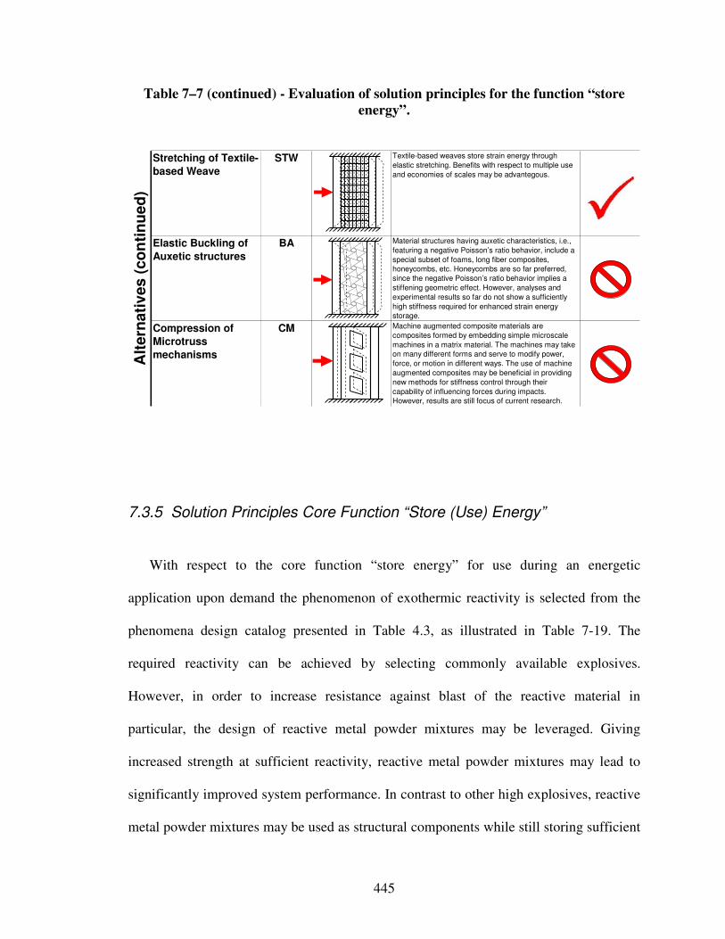
445
Table 7–7 (continued) - Evaluation of solution principles for the function “store
energy”.
Stretching of Textile-
based Weave
STW Textile-based weaves store strain energy through
elastic stretching. Benefits with respect to multiple use
and economies of scales may be advantegous.
Elastic Buckling of
Auxetic structures
BA Material structures having auxetic characteristics, i.e.,
featuring a negative Poisson’s ratio behavior, include a
special subset of foams, long fiber composites,
honeycombs, etc. Honeycombs are so far preferred,
since the negative Poisson’s ratio behavior implies a
stiffening geometric effect. However, analyses and
experimental results so far do not show a sufficiently
high stiffness required for enhanced strain energy
storage.
Compression of
Microtruss
mechanisms
CM Machine augmented composite materials are
composites formed by embedding simple microscale
machines in a matrix material. The machines may take
on many different forms and serve to modify power,
force, or motion in different ways. The use of machine
augmented composites may be beneficial in providing
new methods for stiffness control through their
capability of influencing forces during impacts.
However, results are still focus of current research.
Alt
ern
ati
ves
(co
nti
nu
ed
)
7.3.5 Solution Principles Core Function “Store (Use) Energy”
With respect to the core function “store energy” for use during an energetic
application upon demand the phenomenon of exothermic reactivity is selected from the
phenomena design catalog presented in Table 4.3, as illustrated in Table 7-19. The
required reactivity can be achieved by selecting commonly available explosives.
However, in order to increase resistance against blast of the reactive material in
particular, the design of reactive metal powder mixtures may be leveraged. Giving
increased strength at sufficient reactivity, reactive metal powder mixtures may lead to
significantly improved system performance. In contrast to other high explosives, reactive
metal powder mixtures may be used as structural components while still storing sufficient

446
energy for the customer’s energetic application during the use phase. These materials are
unique in that the components serve the dual purpose of providing both energetic fuel and
structural integrity.
Core function:
Concept
Principle
Phenomenon
Function
Phenomenon:
Exothermic
reactivity
Store (strain) energy
Ekin
Figure 7-18 - Mapping solution principles to phenomenon exothermic reactivity to
embody system level function "store (use) energy".
Strength approximations for a specific reactive metal powder mixture (FeAl2O3) are
given in Table 7-3. Modeling reactive powder metal mixtures however involves scientific
phenomena and associated governing solution principles from nano-, micro-, continuum-
and up to system-level scales and hence requires a complex network of information
transformations on multiple scales to predict strength and reaction initiation. In the design
of MESMs, analytical, experimental and computational tools are employed at multiple
length scales, i.e., from nano-, micro-, continuum- and system-level length-scales, as
illustrated in Figure 7-19. Ab initio and molecular dynamics calculations are conducted to
estimate the equation of state for the individual constituents and for reacting elements to
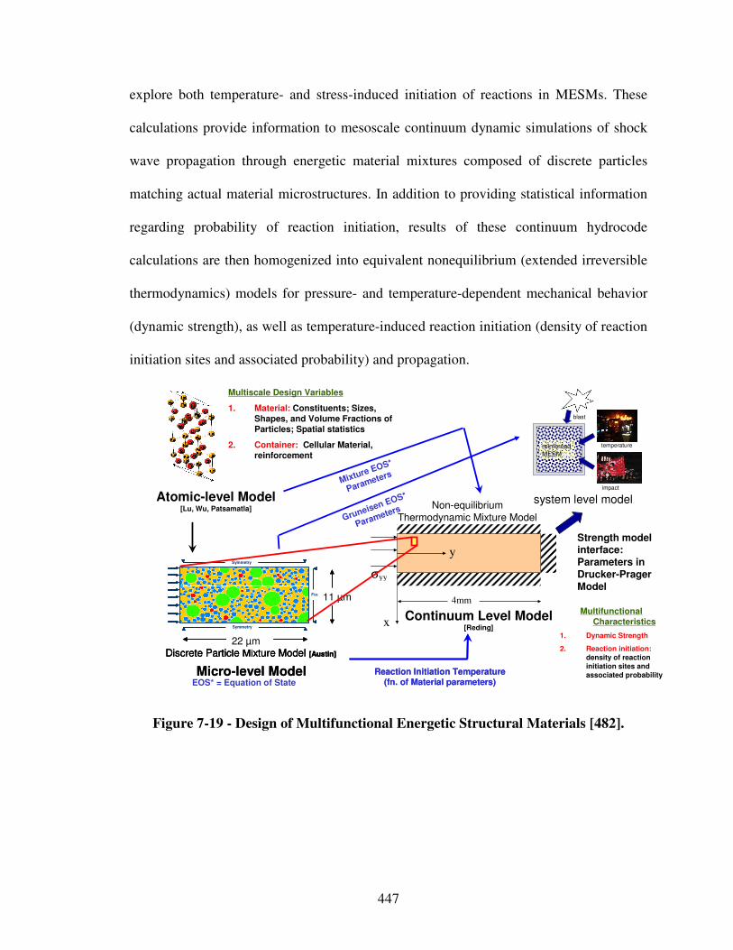
447
explore both temperature- and stress-induced initiation of reactions in MESMs. These
calculations provide information to mesoscale continuum dynamic simulations of shock
wave propagation through energetic material mixtures composed of discrete particles
matching actual material microstructures. In addition to providing statistical information
regarding probability of reaction initiation, results of these continuum hydrocode
calculations are then homogenized into equivalent nonequilibrium (extended irreversible
thermodynamics) models for pressure- and temperature-dependent mechanical behavior
(dynamic strength), as well as temperature-induced reaction initiation (density of reaction
initiation sites and associated probability) and propagation.
y
x
σyy
4mm
Discrete Particle Mixture Model [Austin]
Symmetry
Symmetry
Fixed
22 µm
11 µm
Micro-level Model
Discrete Particle Mixture Model [Austin]
Symmetry
Symmetry
Fixed
22 µm
11 µm
Discrete Particle Mixture Model [Austin]
Symmetry
Symmetry
Fixed
22 µm
11 µm
Micro-level Model
Multiscale Design Variables
1. Material: Constituents; Sizes, Shapes, and Volume Fractions of Particles; Spatial statistics
2. Container: Cellular Material, reinforcement
Multifunctional Characteristics
1. Dynamic Strength
2. Reaction initiation:density of reaction initiation sites and associated probability
Gruneisen EOS*
Parameters
Reaction Initiation Temperature (fn. of Material parameters)
Reaction Initiation Temperature (fn. of Material parameters)EOS* = Equation of State
Atomic-level Model[Lu, Wu, Patsamatla] Non-equilibrium
Thermodynamic Mixture Model
Continuum Level Model[Reding]
Mixture EOS*
Parameters
system level model
temperature
impact
reinforcedMESM
blast
Strength model interface:Parameters in Drucker-PragerModel
Figure 7-19 - Design of Multifunctional Energetic Structural Materials [482].
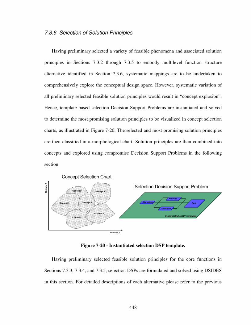
448
7.3.6 Selection of Solution Principles
Having preliminary selected a variety of feasible phenomena and associated solution
principles in Sections 7.3.2 through 7.3.5 to embody multilevel function structure
alternative identified in Section 7.3.6, systematic mappings are to be undertaken to
comprehensively explore the conceptual design space. However, systematic variation of
all preliminary selected feasible solution principles would result in “concept explosion”.
Hence, template-based selection Decision Support Problems are instantiated and solved
to determine the most promising solution principles to be visualized in concept selection
charts, as illustrated in Figure 7-20. The selected and most promising solution principles
are then classified in a morphological chart. Solution principles are then combined into
concepts and explored using compromise Decision Support Problems in the following
section.
Att
rib
ute
2
Attribute 1
Concept 2
Concept 5
Concept 1 Concept 3
Concept 6
Concept 4
AlternativesRank
Instantiated sDSP Template
Importance
Attributes
Selection Decision Support Problem
Concept Selection Chart
Figure 7-20 - Instantiated selection DSP template.
Having preliminary selected feasible solution principles for the core functions in
Sections 7.3.3, 7.3.4, and 7.3.5, selection DSPs are formulated and solved using DSIDES
in this section. For detailed descriptions of each alternative please refer to the previous
449
sections in which those have been selected based primarily on qualitative rather than
quantitative information on their feasibility in the given problem context. Ranking of
feasible alternatives in order of preference based on selection DSPs is addressed in the
following.
As described in Section 7.3.5, modeling reactive powder metal mixtures involves
scientific phenomena and associated governing solution principles from nano-, micro-,
continuum- and up to system-level scales and hence requires a complex network of
information transformations on multiple scales to predict strength and reaction initiation.
Embodiment design processes of structurally reinforced (composite) reactive powder
metal mixture have been investigated by Panchal and coauthors [478] as well as Choi and
coauthors [131]. Due to high cost and resources involved, the design of reactive metal
powder mixtures is not considered further in this work, as illustrated in Table 7-14.
Hence, focus is on designing a containment system consisting of blast resistant panel
configurations enclosing a reactive material featuring sufficient reactivity for the later
energetic application.
The selection DSP formulations in the following involve multiple attributes, namely:
• Maximum strength indicator: Quantitative information on a ratio scale
representing the normalized maximum stress level during crushing as a function
of relative densities for each material system. A larger number indicates
preference. Bounds range from 0 to 1. For example, a strength indicator range
with a maximum of 0.7 is obtained for the progressive buckling of open-top tubes
and frustra using the relative density range and strength approximation given in
the design catalog for aluminum as a benchmark.
450
• Strength indicator at ρρρρrel = 0.1: Quantitative information on a ratio scale
representing the normalized stress level during crushing at a relative density of
0.1. Since relative densities above 0.1 can’t be realized with some material
systems, the strength level at a relative density of 0.1 is chosen as a benchmark.
Apart from using ρrel = 0.1, determining a strength indicator of 0.4 for the
progressive buckling of open-top tubes and frustra is analogous to determining the
maximum strength indicator described above. A larger number indicates
preference. Bounds range from 0 to 1.
• Maximum dissipation indicator: Quantitative information on a ratio scale
representing the normalized maximum dissipated energy as a function of relative
density and densification strain. A larger number indicates preference. Bounds
range from 0 to 1. For example, a maximum dissipation indicator of 0.8 is
obtained for the progressive buckling of open-top tubes and frustra by multiplying
the maximum strength indicator with the maximum densification strain.
• Maximum stiffness indicator: Quantitative information on a ratio scale
representing the normalized maximum stiffness as a function of relative densities
for each material system. A larger number indicates preference. Bounds range
from 0 to 1. The maximum stiffness indicator is determined analogously to the
maximum strength indicator using the relative density range and strength
approximation given in the design catalog for aluminum as a benchmark.
• Performance range indicator: Quantitative information on a ratio scale
representing the normalized performance range for the attribute under
consideration, i.e., the maximum minus minimum strength or stiffness as a
451
function of relative densities for each material system. For example, the
maximum minus the minimum strength for progressive buckling of open-top
tubes and frustra yields a performance range indicator of 0.3. A larger number
indicates preference. Bounds range from 0 to 1.
• Realizability indicator: Qualitative information on an interval scale representing
normalized manufacturing complexity and flexibility, as well as resistance against
environmental effects. The viewpoint is presented in Table 7-8. Bounds range
from 0 to 1. For example, a realizability indicator of 0.4 for progressive buckling
of open-top-tubes and frustra is chosen because manufacturing is rather complex
and inflexible, but, resistance against environmental effects is high compared to
the other alternatives. A more detailed description of attribute ratings is given in
Appendix A-2.
• Functionality indicator: Qualitative information on an interval scale representing
normalized functionality and potential for multifunctional enhancement. The
viewpoint is presented in Table 7-9. Bounds range from 0 to 1. For example, a
functionality indicator of 0.4 for progressive buckling of open-top-tubes and
frustra is chosen because this alternative provides functionality in only one
domain, but, has a high potential for multifunctional enhancement. A more
detailed description of attribute ratings is given in Appendix A-2.
The rating method [544], the most commonly used method for rating intangibles, has
been used to create both interval scales for the realizability and functionality. The
outcome is a standardized rating form which has written descriptions of each level of
desirability, as shown in Table 7-8 and Table 7-9. The normalized scales run from 0 to 1
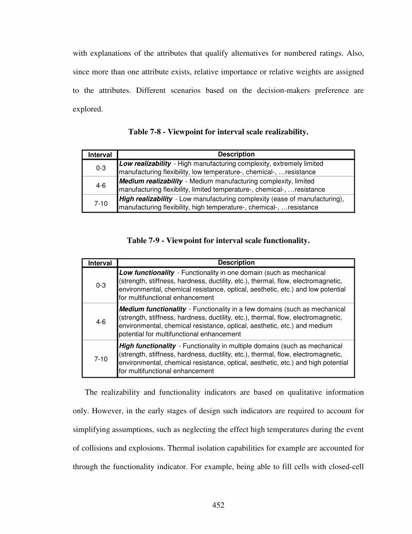
452
with explanations of the attributes that qualify alternatives for numbered ratings. Also,
since more than one attribute exists, relative importance or relative weights are assigned
to the attributes. Different scenarios based on the decision-makers preference are
explored.
Table 7-8 - Viewpoint for interval scale realizability.
Interval
0-3
4-6
7-10High realizability - Low manufacturing complexity (ease of manufacturing),
manufacturing flexibility, high temperature-, chemical-, …resistance
Description
Low realizability - High manufacturing complexity, extremely limited
manufacturing flexibility, low temperature-, chemical-, …resistance
Medium realizability - Medium manufacturing complexity, limited
manufacturing flexibility, limited temperature-, chemical-, …resistance
Table 7-9 - Viewpoint for interval scale functionality.
Interval
0-3
4-6
7-10
High functionality - Functionality in multiple domains (such as mechanical
(strength, stiffness, hardness, ductility, etc.), thermal, flow, electromagnetic,
environmental, chemical resistance, optical, aesthetic, etc.) and high potential
for multifunctional enhancement
Description
Low functionality - Functionality in one domain (such as mechanical
(strength, stiffness, hardness, ductility, etc.), thermal, flow, electromagnetic,
environmental, chemical resistance, optical, aesthetic, etc.) and low potential
for multifunctional enhancement
Medium functionality - Functionality in a few domains (such as mechanical
(strength, stiffness, hardness, ductility, etc.), thermal, flow, electromagnetic,
environmental, chemical resistance, optical, aesthetic, etc.) and medium
potential for multifunctional enhancement
The realizability and functionality indicators are based on qualitative information
only. However, in the early stages of design such indicators are required to account for
simplifying assumptions, such as neglecting the effect high temperatures during the event
of collisions and explosions. Thermal isolation capabilities for example are accounted for
through the functionality indicator. For example, being able to fill cells with closed-cell
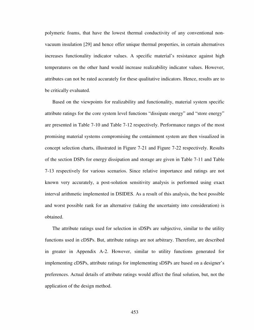
453
polymeric foams, that have the lowest thermal conductivity of any conventional non-
vacuum insulation [29] and hence offer unique thermal properties, in certain alternatives
increases functionality indicator values. A specific material’s resistance against high
temperatures on the other hand would increase realizability indicator values. However,
attributes can not be rated accurately for these qualitative indicators. Hence, results are to
be critically evaluated.
Based on the viewpoints for realizability and functionality, material system specific
attribute ratings for the core system level functions “dissipate energy” and “store energy”
are presented in Table 7-10 and Table 7-12 respectively. Performance ranges of the most
promising material systems compromising the containment system are then visualized in
concept selection charts, illustrated in Figure 7-21 and Figure 7-22 respectively. Results
of the section DSPs for energy dissipation and storage are given in Table 7-11 and Table
7-13 respectively for various scenarios. Since relative importance and ratings are not
known very accurately, a post-solution sensitivity analysis is performed using exact
interval arithmetic implemented in DSIDES. As a result of this analysis, the best possible
and worst possible rank for an alternative (taking the uncertainty into consideration) is
obtained.
The attribute ratings used for selection in sDSPs are subjective, similar to the utility
functions used in cDSPs. But, attribute ratings are not arbitrary. Therefore, are described
in greater in Appendix A-2. However, similar to utility functions generated for
implementing cDSPs, attribute ratings for implementing sDSPs are based on a designer’s
preferences. Actual details of attribute ratings would affect the final solution, but, not the
application of the design method.
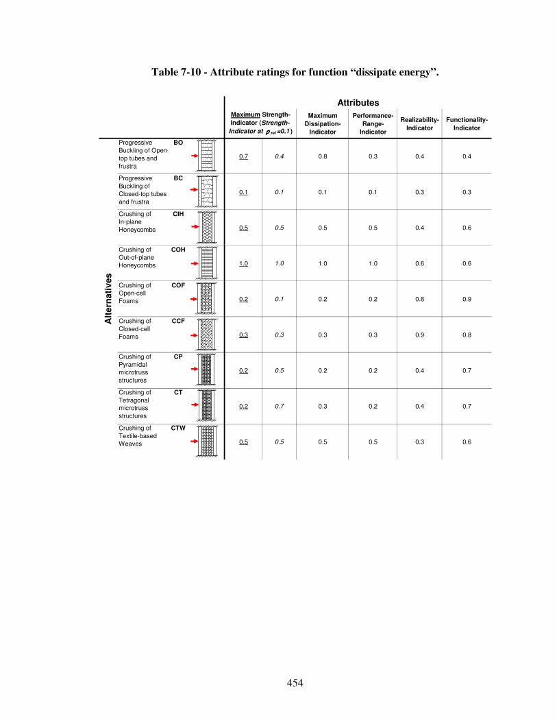
454
Table 7-10 - Attribute ratings for function “dissipate energy”.
Maximum
Dissipation-
Indicator
Performance-
Range-
Indicator
Realizability-
Indicator
Functionality-
Indicator
Progressive
Buckling of Open-
top tubes and
frustra
BO
0.7 0.4 0.8 0.3 0.4 0.4
Progressive
Buckling of
Closed-top tubes
and frustra
BC
0.1 0.1 0.1 0.1 0.3 0.3
Crushing of
In-plane
Honeycombs
CIH
0.5 0.5 0.5 0.5 0.4 0.6
Crushing of
Out-of-plane
Honeycombs
COH
1.0 1.0 1.0 1.0 0.6 0.6
Crushing of
Open-cell
Foams
COF
0.2 0.1 0.2 0.2 0.8 0.9
Crushing of
Closed-cell
Foams
CCF
0.3 0.3 0.3 0.3 0.9 0.8
Crushing of
Pyramidal
microtruss
structures
CP
0.2 0.5 0.2 0.2 0.4 0.7
Crushing of
Tetragonal
microtruss
structures
CT
0.2 0.7 0.3 0.2 0.4 0.7
Crushing of
Textile-based
Weaves
CTW
0.5 0.5 0.5 0.5 0.3 0.6
Maximum Strength-
Indicator (Strength-
Indicator at ρρρρ rel =0.1 )
Alt
ern
ati
ves
Attributes
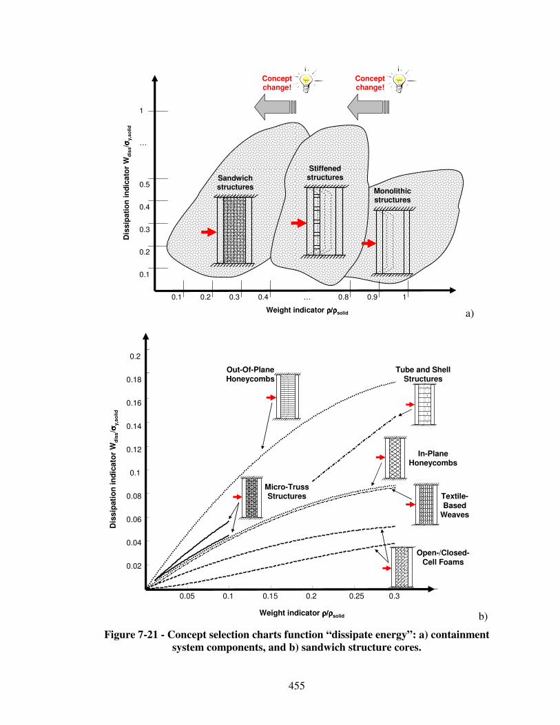
455
Dis
sip
ati
on
in
dic
ato
r W
dis
s/ σσ σσ
y,s
olid
Weight indicator ρ/ρρ/ρρ/ρρ/ρsolid
0.1 0.2 0.3 0.4 … 0.8 0.9 1
0.1
0.2
0.3
0.4
0.5
…
1
Monolithic structures
Stiffened structuresSandwich
structures
Concept change!
Concept change!
a)
0.05 0.1 0.15 0.2 0.25 0.3
0.02
0.04
0.06
0.08
0.1
0.12
0.14
0.16
0.18
0.2
Out-Of-Plane Honeycombs
Tube and Shell Structures
In-Plane Honeycombs
Textile-Based
Weaves
Open-/Closed-Cell Foams
Micro-Truss Structures
Dis
sip
ati
on
in
dic
ato
r W
dis
s/ σσ σσ
y,s
olid
Weight indicator ρ/ρρ/ρρ/ρρ/ρsolid b)
Figure 7-21 - Concept selection charts function “dissipate energy”: a) containment
system components, and b) sandwich structure cores.
456
Table 7-11 - sDSP results energy dissipation on materials level using DSIDES.
Weighting: All attributes equally important
Alternative Rank
Merit
Function
Value
Percentage
Difference
from No.1
Sensitivity
Analysis
Rank
Scaled
Merit Func-
tion Value
COH 1 0.85 0 1 0.84+/-0.17
CCF 2 0.49 42.5 2 to 8 0.48+/-0.10
CIH 3 0.48 43.1 2 to 8 0.47+/-0.09
CTW 4 0.47 45.1 2 to 8 0.46+/-0.09
BO 5 0.46 45.8 2 to 8 0.45+/-0.07
COF 6 0.42 51.0 2 to 8 0.41+/-0.08
CT 7 0.41 51.6 2 to 8 0.40+/-0.08
CP 8 0.36 57.5 2 to 8 0.35+/-0.07
BC 9 0.05 94.1 9 0.05+/-0.01
Weighting: Maximum performance indicator twice as important as other attributes
Alternative Rank
Merit
Function
Value
Percentage
Difference
from No.1
Sensitivity
Analysis
Rank
Scaled
Merit Func-
tion Value
COH 1 0.87 0 1 0.83+/-0.17
BO 2 0.50 43.2 2 to 8 0.47+/-0.09
CIH 3 0.49 44.3 2 to 8 0.47+/-0.09
CTW 4 0.47 45.9 2 to 8 0.45+/-0.09
CCF 5 0.46 47.0 2 to 8 0.44+/-0.07
COF 6 0.39 55.7 2 to 8 0.37+/-0.07
CT 7 0.38 56.3 2 to 8 0.36+/-0.07
CP 8 0.34 61.2 2 to 8 0.32+/-0.06
BC 9 0.04 95.1 9 0.04+/-0.01
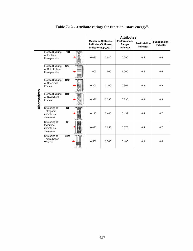
457
Table 7-12 - Attribute ratings for function “store energy”.
Performance-
Range-
Indicator
Realizability-
Indicator
Functionality-
Indicator
Elastic Buckling
of In-plane
Honeycombs
BIH
0.090 0.010 0.090 0.4 0.6
Elastic Buckling
of Out-of-plane
Honeycombs
BOH
1.000 1.000 1.000 0.6 0.6
Elastic Buckling
of Open-cell
Foams
BOF
0.300 0.100 0.301 0.8 0.9
Elastic Buckling
of Closed-cell
Foams
BCF
0.330 0.330 0.330 0.9 0.8
Stretching of
Tetragonal
microtruss
structures
ST
0.147 0.440 0.132 0.4 0.7
Stretching of
Pyramidal
microtruss
structures
SP
0.083 0.250 0.075 0.4 0.7
Stretching of
Textile-based
Weaves
STW
0.500 0.500 0.485 0.3 0.6
Alt
ern
ati
ves
AttributesMaximum Stiffness-
Indicator (Stiffness-
Indicator at ρρρρrel=0.1)
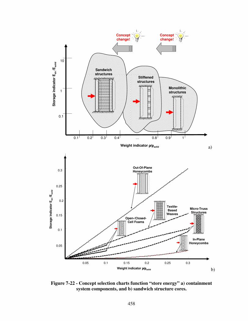
458
Sto
rag
e in
dic
ato
r E
str
./Es
oli
d
Weight indicator ρ/ρρ/ρρ/ρρ/ρsolid
0.1 0.2 0.3 0.4 … 0.8 0.9 1
0.1
1Monolithic structures
Stiffened structures
Sandwich structures
Concept change!
Concept change!
10
a)
0.05 0.1 0.15 0.2 0.25 0.3
0.05
0.1
0.15
0.2
0.25
0.3
Sto
rag
e in
dic
ato
r E
str
./Es
olid
Weight indicator ρ/ρρ/ρρ/ρρ/ρsolid
Out-Of-Plane Honeycombs
In-Plane Honeycombs
Textile-Based
Weaves
Open-/Closed-Cell Foams
Micro-Truss Structures
b)
Figure 7-22 - Concept selection charts function “store energy” a) containment
system components, and b) sandwich structure cores.
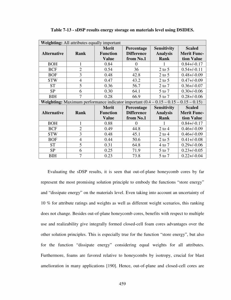
459
Table 7-13 - sDSP results energy storage on materials level using DSIDES.
Weighting: All attributes equally important
Alternative Rank
Merit
Function
Value
Percentage
Difference
from No.1
Sensitivity
Analysis
Rank
Scaled
Merit Func-
tion Value
BOH 1 0.84 0 1 0.84+/-0.17
BCF 2 0.54 36 2 to 5 0.54+/-0.11
BOF 3 0.48 42.8 2 to 5 0.48+/-0.09
STW 4 0.47 43.2 2 to 5 0.47+/-0.09
ST 5 0.36 56.7 2 to 7 0.36+/-0.07
SP 6 0.30 64.1 5 to 7 0.30+/-0.06
BIH 7 0.28 66.9 5 to 7 0.28+/-0.06
Weighting: Maximum performance indicator important (0.4 – 0.15 – 0.15 – 0.15 – 0.15)
Alternative Rank
Merit
Function
Value
Percentage
Difference
from No.1
Sensitivity
Analysis
Rank
Scaled
Merit Func-
tion Value
BOH 1 0.88 0 1 0.84+/-0.17
BCF 2 0.49 44.8 2 to 4 0.46+/-0.09
STW 3 0.48 45.1 2 to 4 0.46+/-0.09
BOF 4 0.44 50.6 2 to 5 0.41+/-0.08
ST 5 0.31 64.8 4 to 7 0.29+/-0.06
SP 6 0.25 71.9 5 to 7 0.23+/-0.05
BIH 7 0.23 73.8 5 to 7 0.22+/-0.04
Evaluating the sDSP results, it is seen that out-of-plane honeycomb cores by far
represent the most promising solution principle to embody the functions “store energy”
and “dissipate energy” on the materials level. Even taking into account an uncertainty of
10 % for attribute ratings and weights as well as different weight scenarios, this ranking
does not change. Besides out-of-plane honeycomb cores, benefits with respect to multiple
use and realizability give integrally formed closed-cell foam cores advantages over the
other solution principles. This is especially true for the function “store energy”, but also
for the function “dissipate energy” considering equal weights for all attributes.
Furthermore, foams are favored relative to honeycombs by isotropy, crucial for blast
amelioration in many applications [190]. Hence, out-of-plane and closed-cell cores are
460
further explored even though analysis of selection results indicates that out-of-plane
feature superior performance characteristics. However, it is emphasized that sDSP results
are characterized by uncertainty. Therefore, not only out-of-plane honeycomb cores, but
also closed-cell foam cores due to the multifunctionality and performance characteristics
as well as simple and stiffened panels due to their simplicity and performance
characteristics are further explored in the following.
Based on these results, selected solution principles are listed in the morphological
matrix shown in Table 7-14 for the core functions “dissipate energy”, “store (strain)
energy”, and “store (use) energy”. As illustrated in the morphological matrix and
described in the beginning of this section, the design of reactive powder metal mixture is
not considered any further in this work. Hence, depending on the energetic application, a
reactive material is selected. Therefore, in the following, focus shifts to designing a
containment system to protect the reactive material from blasts.
However, considering combinations of solution principles listed in the morphological
matrix, many principal solution alternatives for the containment system can be readily
generated through systematic variation. For example, a coincidental principal solution to
the reactive material containment system problem is the combination of:
i) a reactive material (core function C, alternative 1), protected by
ii) solid panels (core function B, solution principle 3),
selected from a finite set of available materials. Solid panels provide an adequate level of
protection whereas the reactive material only ensures sufficient reactivity.
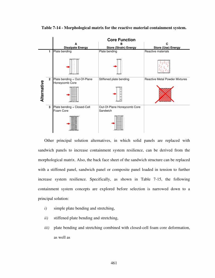
461
Table 7-14 - Morphological matrix for the reactive material containment system.
A B C
Dissipate Energy Store (Strain) Energy Store (Use) Energy
1 Plate bending Plate bending Reactive materials
2 Plate bending + Out-Of-Plane
Honeycomb Core
Stiffened plate bending Reactive Metal Powder Mixtures
3 Plate bending + Closed-Cell
Foam Core
Out-Of-Plane Honeycomb Core
Sandwich
Alt
ern
ati
ve
Core Function
Other principal solution alternatives, in which solid panels are replaced with
sandwich panels to increase containment system resilience, can be derived from the
morphological matrix. Also, the back face sheet of the sandwich structure can be replaced
with a stiffened panel, sandwich panel or composite panel loaded in tension to further
increase system resilience. Specifically, as shown in Table 7-15, the following
containment system concepts are explored before selection is narrowed down to a
principal solution:
i) simple plate bending and stretching,
ii) stiffened plate bending and stretching,
iii) plate bending and stretching combined with closed-cell foam core deformation,
as well as
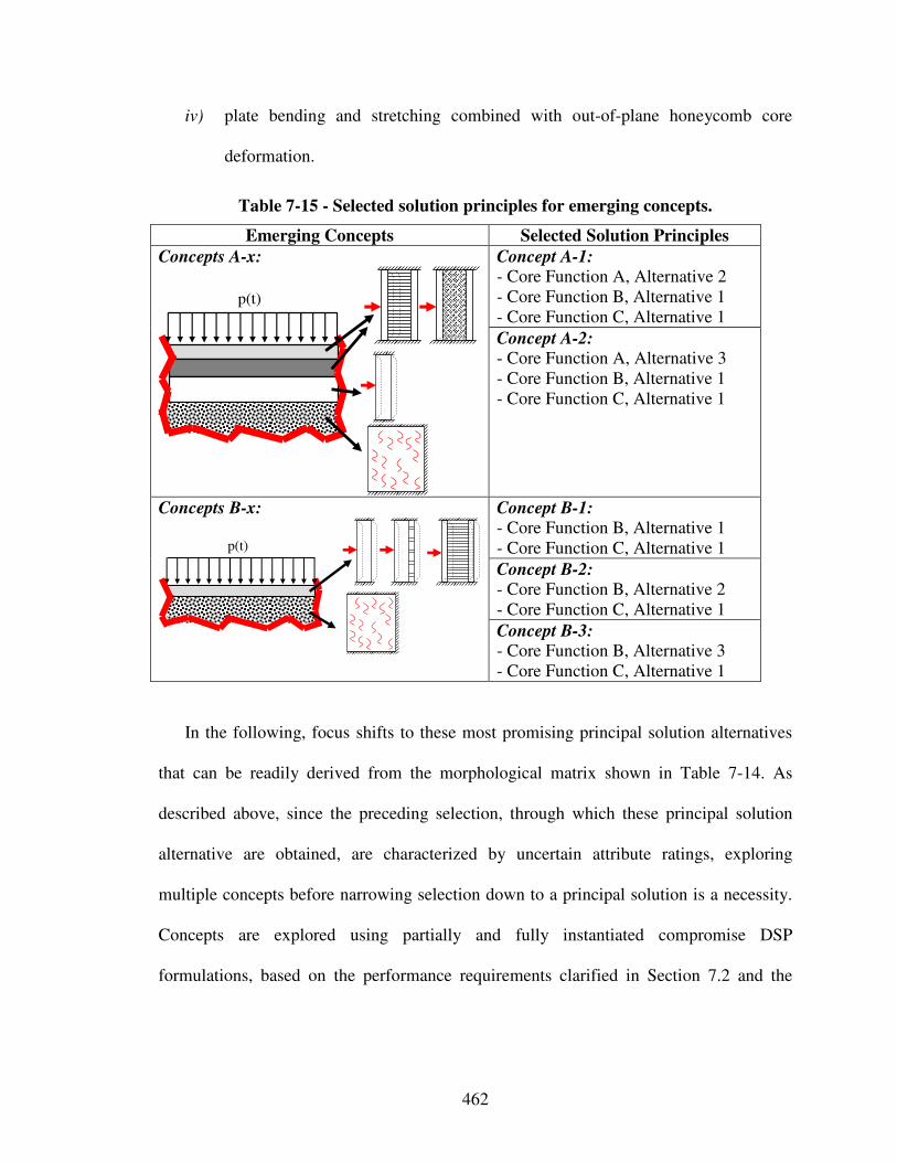
462
iv) plate bending and stretching combined with out-of-plane honeycomb core
deformation.
Table 7-15 - Selected solution principles for emerging concepts.
Emerging Concepts Selected Solution Principles
Concept A-1: - Core Function A, Alternative 2 - Core Function B, Alternative 1 - Core Function C, Alternative 1
Concepts A-x:
p(t)
Concept A-2: - Core Function A, Alternative 3 - Core Function B, Alternative 1 - Core Function C, Alternative 1
Concept B-1: - Core Function B, Alternative 1 - Core Function C, Alternative 1
Concept B-2: - Core Function B, Alternative 2 - Core Function C, Alternative 1
Concepts B-x:
p(t)
Concept B-3: - Core Function B, Alternative 3 - Core Function C, Alternative 1
In the following, focus shifts to these most promising principal solution alternatives
that can be readily derived from the morphological matrix shown in Table 7-14. As
described above, since the preceding selection, through which these principal solution
alternative are obtained, are characterized by uncertain attribute ratings, exploring
multiple concepts before narrowing selection down to a principal solution is a necessity.
Concepts are explored using partially and fully instantiated compromise DSP
formulations, based on the performance requirements clarified in Section 7.2 and the
463
design goals of minimum weight and maximum blast resistance while ensuring
satisfactory reactivity.
7.4 Step 2 – Concept Exploration Using Partially and Fully Instantiated Compromise DSP Formulations
Having evaluated and selected phenomena and associated solution principles in
Section 7.3, the most promising principal solution alternatives derived from the
morphological chart as shown in Table 7-15, are explored in this section using partially
and fully instantiated compromise Decision Support Problem formulations reviewed in
Section 2.1.1. Modeling the reactive material is not considered further. Depending on the
energetic application, an energetic material is selected. Hence, focus shifts on narrowing
selection down to a principal containment system solution. As described in Section 7.2
and shown in Figure 7-5, the cubic containment system is comprised of blast resistant
panels. Therefore, only blast resistant panel concepts are considered in the following.
Fundamental blast resistant panel modeling assumptions are clarified in Section 7.2.
Then, in Section 7.4, concept exploration using partially instantiated compromise DSPs is
conducted first to explore the embodiment design space. This is a necessary activity to
fully instantiate compromise DSPs templates for concept exploration correctly, as
addressed in Section 7.4 also. Finally, in Section 7.5, concept exploration results are
analyzed and concept selection is narrowed down to a principal solution. A pictorial
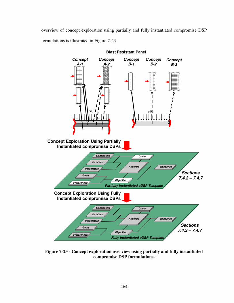
464
overview of concept exploration using partially and fully instantiated compromise DSP
formulations is illustrated in Figure 7-23.
Concept Exploration Using Partially Instantiated compromise DSPs
Concept Exploration Using Fully Instantiated compromise DSPs
Goals
Preferences
Variables
Parameters
Constraints
Response
Objective
Analysis
Driver
Fully Instantiated cDSP Template
Goals
Preferences
Variables
Parameters
Constraints
Response
Objective
Analysis
Driver
Partially Instantiated cDSP Template
Sections 7.4.3 – 7.4.7
Sections 7.4.3 – 7.4.7
p(t) p(t)
ConceptA-1
ConceptA-2
ConceptB-1
ConceptB-2
Concept
B-3
Blast Resistant Panel
Figure 7-23 - Concept exploration overview using partially and fully instantiated
compromise DSP formulations.
465
7.4.1 Fundamental Blast Resistant Panel Modeling Assumptions
Finite element analyses (FEA) of various blast resistant panel concepts are leveraged
for functionally integrated modeling and concept exploration. The commercial software
package ABAQUS 6.6 CAE in its explicit version has been used to conduct simulations.
ABAQUS explicit is a well established tool in the materials domain to predict accurately
the plastic deformation. ABAQUS models have been developed and validated by Jin
Song, an undergraduate researcher in the Systems Realization Laboratory at Georgia
Tech. Subsequently, Gautam Puri, also an undergraduate research in the Systems
Realization Laboratory at Georgia Tech, has transformed these models into scripts that
can be read and executed by the interpreter built into ABAQUS. The script mode allows
to selectively iterate specific sections of the underlying ABAQUS code if desired and
automate repetitive tasks.
The full-size blast resistant panel is assumed to be clamped on all edges and hence
symmetrical in x and y direction. Hence, in order to reduce the simulation time, the full-
size panel is divided into quarter panels of which only one is simulated. As shown in
Figure 7-24, quarter panel 1 and 2 are symmetric with respect to the y axis. Hence, they
are free to move and deform in the y direction but constrained in x direction along the y
axis. Also, they are free to rotate in x direction while rotationally constrained in y
direction. The same condition is applied on the bottom edge of panel 1 by only switching
y and x directions.
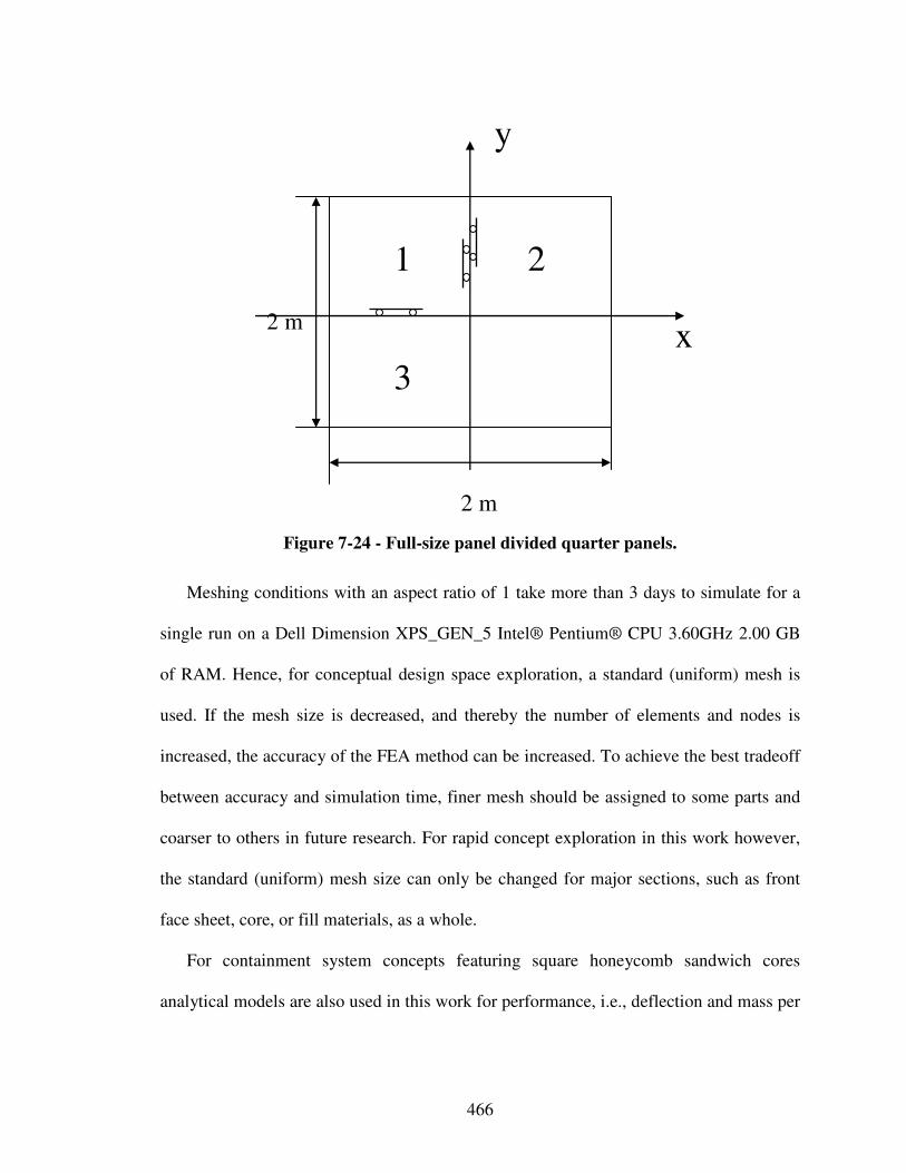
466
2 m
x
y
2 m
1 2
3
Figure 7-24 - Full-size panel divided quarter panels.
Meshing conditions with an aspect ratio of 1 take more than 3 days to simulate for a
single run on a Dell Dimension XPS_GEN_5 Intel® Pentium® CPU 3.60GHz 2.00 GB
of RAM. Hence, for conceptual design space exploration, a standard (uniform) mesh is
used. If the mesh size is decreased, and thereby the number of elements and nodes is
increased, the accuracy of the FEA method can be increased. To achieve the best tradeoff
between accuracy and simulation time, finer mesh should be assigned to some parts and
coarser to others in future research. For rapid concept exploration in this work however,
the standard (uniform) mesh size can only be changed for major sections, such as front
face sheet, core, or fill materials, as a whole.
For containment system concepts featuring square honeycomb sandwich cores
analytical models are also used in this work for performance, i.e., deflection and mass per
467
area, predictions. Performance predictions are based on the work of Fleck and Deshpande
[210], Hutchinson and Xue [286], as well as Muchnik and coauthors [438].
Following the three phase deformation theory, the impulse of the blast is received by
the front face sheet and momentum is transferred in Phase 1. In Phase 2, some of the
kinetic energy is dissipated through crushing of the core layer. The crushing strain is used
to determine the crushed height of the core layer and is derived by equating the plastic
dissipation per unit area in the core to the loss of kinetic energy per unit area in Phase 2.
In Phase 3, the remaining kinetic energy must be dissipated through bending and
stretching of the back face sheet. The equation for deflection is derived by equating the
remaining kinetic energy per unit area to the plastic work per unit area dissipated through
bending and stretching. The average plastic work per unit area dissipated in Phase 3 is
estimated by summing the dissipation from bending and stretching. Blast pressure
loading is modeled through an impulse load defined by the characteristic time t0 (10-4 s)
and peak pressure p0 (25x106 Pa). The equation for deflection δ is determined by
equating the average plastic work per unit area dissipated in Phase 3 to the kinetic energy
at the end of Phase 2 and is shown in Equation 10. Here, hc, hf, and hb are the thickness
of core webs and face sheets, cε is the average crushing strain, ,H H are the thickness of
undeformed and deformed core, λc, and λs are factors governing strength of core in crush
and stretch, ρf, ρb, and ρc are the density of front face sheet material, back face sheet
material, and core base material, Rc is the relative density of the core, as well as σY,f, σY,b,
and σY,c are the yield strength of front face sheet material, back face sheet material, and
core base material. The mass/area M is given in Equation 11. For details in deriving these
equations, the interested reader is referred to the literature [438].
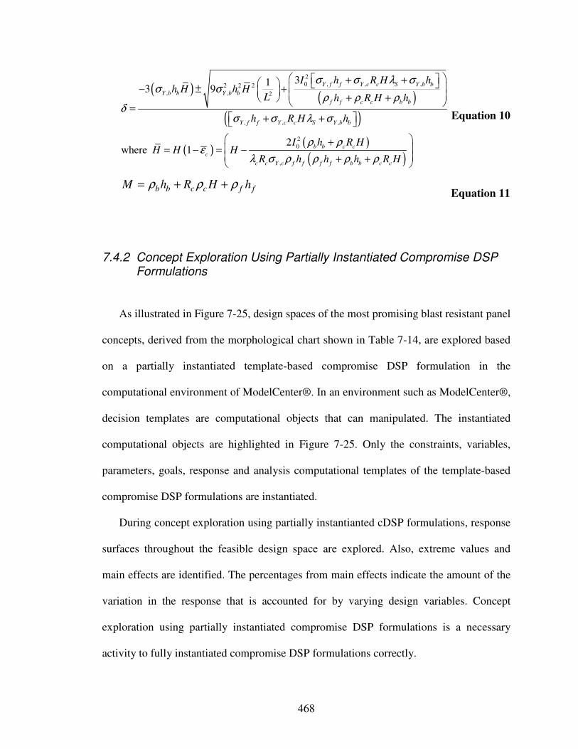
468
( )( )
( )
( )( )
( )
2
0 , , ,2 2 2
, , 2
, , ,
2
0
,
313 9
2where 1
Y f f Y c c S Y b b
Y b b Y b b
f f c c b b
Y f f Y c c S Y b b
b b c c
c
c c Y c f f f f b b c c
I h R H hh H h H
L h R H h
h R H h
I h R HH H H
R h h h R H
σ σ λ σσ σ
ρ ρ ρδ
σ σ λ σ
ρ ρε
λ σ ρ ρ ρ ρ
+ + − ± + + + =
+ +
+ = − = − + +
Equation 10
b b c c f fM h R H hρ ρ ρ= + + Equation 11
7.4.2 Concept Exploration Using Partially Instantiated Compromise DSP Formulations
As illustrated in Figure 7-25, design spaces of the most promising blast resistant panel
concepts, derived from the morphological chart shown in Table 7-14, are explored based
on a partially instantiated template-based compromise DSP formulation in the
computational environment of ModelCenter®. In an environment such as ModelCenter®,
decision templates are computational objects that can manipulated. The instantiated
computational objects are highlighted in Figure 7-25. Only the constraints, variables,
parameters, goals, response and analysis computational templates of the template-based
compromise DSP formulations are instantiated.
During concept exploration using partially instantianted cDSP formulations, response
surfaces throughout the feasible design space are explored. Also, extreme values and
main effects are identified. The percentages from main effects indicate the amount of the
variation in the response that is accounted for by varying design variables. Concept
exploration using partially instantiated compromise DSP formulations is a necessary
activity to fully instantiated compromise DSP formulations correctly.
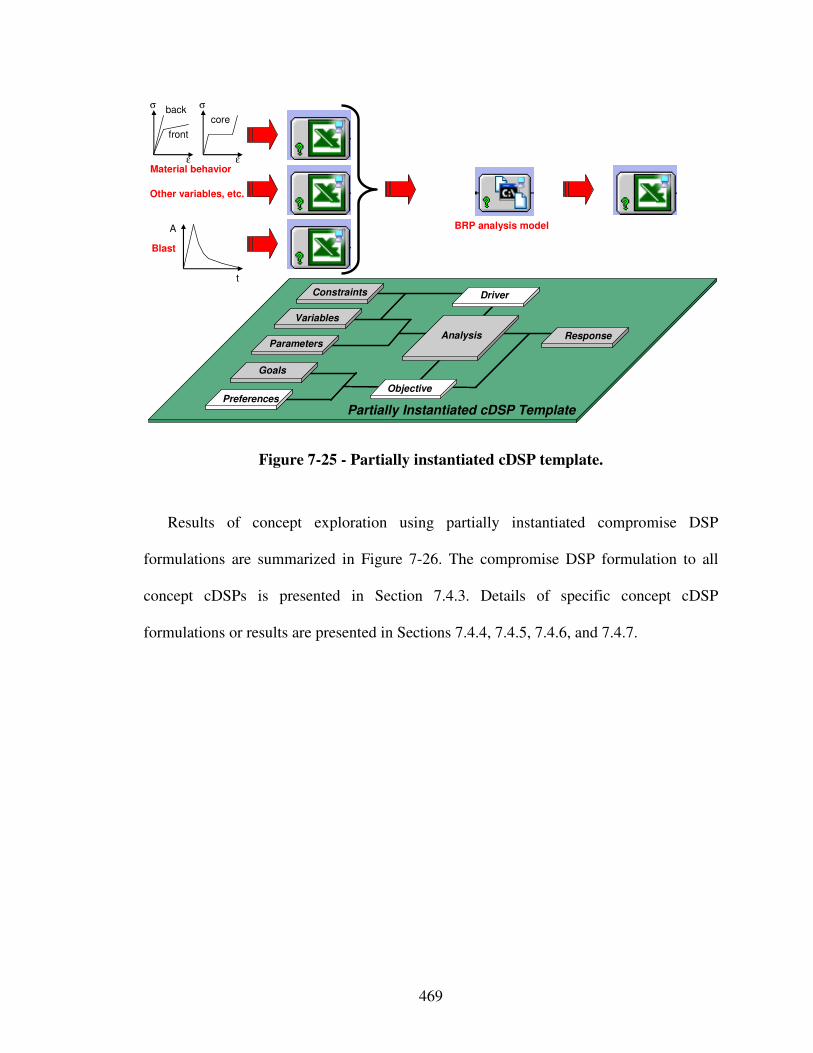
469
Goals
Preferences
Variables
Parameters
Constraints
Response
Objective
Analysis
Driver
Partially Instantiated cDSP Template
BRP analysis model
core
front
backσ σ
εε
Blast
A
t
Other variables, etc.
Material behavior
Figure 7-25 - Partially instantiated cDSP template.
Results of concept exploration using partially instantiated compromise DSP
formulations are summarized in Figure 7-26. The compromise DSP formulation to all
concept cDSPs is presented in Section 7.4.3. Details of specific concept cDSP
formulations or results are presented in Sections 7.4.4, 7.4.5, 7.4.6, and 7.4.7.
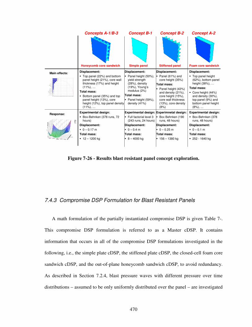
470
Displacement:
� Panel height (50%), yield strength (28%), density (19%), Young’s modulus (2%)
Total mass:
� Panel height (59%), density (41%)
Experimental design:
� Full factorial level 3 (243 runs, 24 hours)
Displacement:
� 0 – 0.4 m
Total mass:
� 8 – 4000 kg
Displacement:
� Panel (61%) and core height (35%)
Total mass:
� Panel height (43%) and density (21%), core height (15%), core wall thickness (13%), core density (8%)
Experimnetal design:
� Box Behnken (190 runs, 48 hours)
Displacement:
� 0 – 0.25 m
Total mass:
� 156 – 1380 kg
Displacement:
� Top panel height (62%), bottom panel height (38%), …
Total mass:
� Core height (44%) and density (30%), top panel (9%) and bottom panel height (8%), …
Experimental design:
� Box-Behnken (378 runs, 48 hours)
Displacement:
� 0 – 0.1 m
Total mass:
� 252 - 1640 kg
Displacement:
� Top panel (22%) and bottom panel height (21%), core wall thickness (17%) and height (11%), …
Total mass:
� Bottom panel (35%) and top panel height (13%), core height (12%), top panel density (11%), …
Experimental design:
� Box-Behnken (378 runs, 72 hours)
Displacement:
� 0 – 0.17 m
Total mass:
� 12 – 1200 kg
Response:
Main effects:
Honeycomb core sandwich Foam core sandwichSimple panel Stiffened panel
Concepts A-1/B-3 Concept A-2Concept B-1 Concept B-2
Figure 7-26 - Results blast resistant panel concept exploration.
7.4.3 Compromise DSP Formulation for Blast Resistant Panels
A math formulation of the partially instantiated compromise DSP is given Table 7-.
This compromise DSP formulation is referred to as a Master cDSP. It contains
information that occurs in all of the compromise DSP formulations investigated in the
following, i.e., the simple plate cDSP, the stiffened plate cDSP, the closed-cell foam core
sandwich cDSP, and the out-of-plane honeycomb sandwich cDSP, to avoid redundancy.
As described in Section 7.2.4, blast pressure waves with different pressure over time
distributions – assumed to be only uniformly distributed over the panel – are investigated
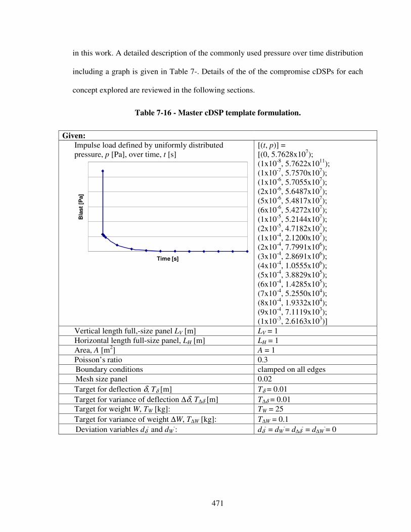
471
in this work. A detailed description of the commonly used pressure over time distribution
including a graph is given in Table 7-. Details of the of the compromise cDSPs for each
concept explored are reviewed in the following sections.
Table 7-16 - Master cDSP template formulation.
Given:
Impulse load defined by uniformly distributed pressure, p [Pa], over time, t [s]
Time [s]
Bla
st
[Pa]
[(t, p)] = [(0, 5.7628x10⁷); (1x10⁻⁸, 5.7622x10¹¹); (1x10⁻⁷, 5.7570x10⁷); (1x10⁻⁶, 5.7055x10⁷); (2x10⁻⁶, 5.6487x10⁷); (5x10⁻⁶, 5.4817x10⁷); (6x10⁻⁶, 5.4272x10⁷); (1x10⁻⁵, 5.2144x10⁷); (2x10⁻⁵, 4.7182x10⁷); (1x10⁻⁴, 2.1200x10⁷); (2x10⁻⁴, 7.7991x10⁶); (3x10⁻⁴, 2.8691x10⁶); (4x10⁻⁴, 1.0555x10⁶); (5x10⁻⁴, 3.8829x10⁵); (6x10⁻⁴, 1.4285x10⁵); (7x10⁻⁴, 5.2550x10⁴); (8x10⁻⁴, 1.9332x10⁴); (9x10⁻⁴, 7.1119x10³); (1x10⁻³, 2.6163x10³)]
Vertical length full,-size panel LV [m] LV = 1
Horizontal length full-size panel, LH [m] LH = 1
Area, A [m2] A = 1
Poisson’s ratio 0.3
Boundary conditions clamped on all edges
Mesh size panel 0.02
Target for deflection δ, Tδ [m] Tδ = 0.01
Target for variance of deflection ∆δ, T∆δ [m] T∆δ = 0.01
Target for weight W, TW [kg]: TW = 25
Target for variance of weight ∆W, T∆W [kg]: T∆W = 0.1
Deviation variables dδ- and dW
-: dδ- = dW
-= d∆δ- = d∆W
-= 0
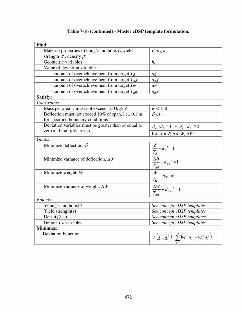
472
Table 7-16 (continued) - Master cDSP template formulation.
Find:
Material properties (Young’s modulus E, yield
strength σY, density ρ):
E, σY, ρ
Geometric variables hi
Value of deviation variables:
- amount of overachievement from target Tδ dδ+
- amount of overachievement from target T∆δ d∆δ+
- amount of overachievement from target TW dW+
- amount of overachievement from target T∆W d∆W+
Satisfy:
Constraints:
Mass per area w must not exceed 150 kg/m2 w < 150
Deflection must not exceed 10% of span, i.e., 0.1 m, for specified boundary conditions
δ < 0.1
0,0 ≥∧=⋅−+−+
iiii dddd Deviation variables must be greater than or equal to zero and multiply to zero
for i = δ, ∆δ, W, ∆W
Goals:
Minimize deflection, δ 1=−
+
δ
δ
δd
T
Minimize variance of deflection, ∆δ 1=−
∆ +
∆
∆
δ
δ
δd
T
Minimize weight, W 1=−
+
W
W
dT
W
Minimize variance of weight, ∆W 1=−
∆ +
∆
∆
W
W
dT
W
Bounds:
Young’s modulus(i) See concept cDSP templates
Yield strength(s) See concept cDSP templates
Density(ies) See concept cDSP templates
Geometric variables See concept cDSP templates
Minimize:
Deviation Function ( ) ( )∑=
++−−+−+=
m
i
iiii dWdWddZ1
,
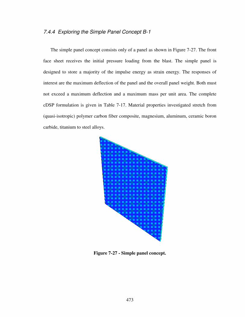
473
7.4.4 Exploring the Simple Panel Concept B-1
The simple panel concept consists only of a panel as shown in Figure 7-27. The front
face sheet receives the initial pressure loading from the blast. The simple panel is
designed to store a majority of the impulse energy as strain energy. The responses of
interest are the maximum deflection of the panel and the overall panel weight. Both must
not exceed a maximum deflection and a maximum mass per unit area. The complete
cDSP formulation is given in Table 7-17. Material properties investigated stretch from
(quasi-isotropic) polymer carbon fiber composite, magnesium, aluminum, ceramic boron
carbide, titanium to steel alloys.
Figure 7-27 - Simple panel concept.
474
Table 7-17 - cDSP template formulation simple panel concept.
Given:
See Master cDSP template
Find:
Material properties (Young’s modulus E, Poisson’s
ratio ν, yield strength σY, density ρ): E, ν, σY, ρ
Panel thickness h h
Value of deviation variables:
See Master cDSP template
Satisfy:
Constraints:
See Master cDSP template
Goals:
See Master cDSP template
Bounds:
Young’s modulus panel, E [Pa] 40x109 < E < 450x109
Yield strength panel, σY [Pa] 30x106 ≤ σY ≤ 4510x106
Density panel, ρ [kg/m3] 1550 ≤ ρ ≤ 7850
Panel thickness h [m] 0.005 ≤ h ≤ 0.5
Minimize:
See Master cDSP template
As a result of exploring this concept using a FEA model and level 3 full factorial
sampling method (243 runs, 24 hours), the following main effects have been identified
concerning the response deflection: panel height (50 %), yield strength (28 %), density
(19 %), and Young’s modulus (2 %), and concerning the response total mass: panel
height (59 %), and density (41 %). Response surface plots of selected main effects are
shown in Figure C-11 and Figure C-12 in Appendix A-3. Results and response surface
progressions are in line with physical reasoning and give a first estimation of the
embodiment design space. Extreme values within the given bounds on the design
variables range from 0 to 0.4 m for the response displacement and from 8 to 4000 kg for
the response total mass.
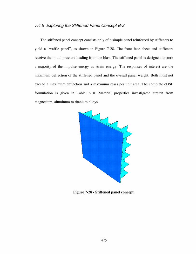
475
7.4.5 Exploring the Stiffened Panel Concept B-2
The stiffened panel concept consists only of a simple panel reinforced by stiffeners to
yield a “waffle panel”, as shown in Figure 7-28. The front face sheet and stiffeners
receive the initial pressure loading from the blast. The stiffened panel is designed to store
a majority of the impulse energy as strain energy. The responses of interest are the
maximum deflection of the stiffened panel and the overall panel weight. Both must not
exceed a maximum deflection and a maximum mass per unit area. The complete cDSP
formulation is given in Table 7-18. Material properties investigated stretch from
magnesium, aluminum to titanium alloys.
Figure 7-28 - Stiffened panel concept.
476
Table 7-18 - cDSP formulation stiffened panel concept.
Given:
See Master cDSP template
Cell spacing, B [m] B = 0.1
Cell shape square
Boundary conditions clamped on all edges
Mesh size front face sheet 0.02
Mesh size core 0.02
Find:
Material properties (Young’s modulus E, Poisson’s
ratio ν, yield strength σY, density ρ):
- front face sheet Ef, νf, σY,f, ρf
- core Ec, νc, σY,c, ρc
Geometry:
- front face sheet thickness hf
- core thickness H
- core wall thickness hc
Value of deviation variables:
See Master cDSP template
Satisfy:
Constraints:
See Master cDSP template
Goals:
See Master cDSP template
Bounds:
Young’s modulus front face sheet, Ef [Pa] 40x109 < Ef < 140x109
Yield strength front face sheet, σY,f [Pa] 30x106 ≤ σY.f ≤ 1250x106
Density front face sheet, ρf [kg/m3] 1700 ≤ ρf ≤ 4900
Young’s modulus core, Ec [Pa] 40x109 < Ef < 140x109
Yield strength core, σY,c [Pa] 30x106 ≤ σY.f ≤ 1250x106
Density core, ρc [kg/m3] 1700 ≤ ρc ≤ 4900
Front face sheet thickness hf [m] 0.001 ≤ hf ≤ 0.25
Core thickness H [m] 0.01 ≤ H ≤ 0.25
Core wall thickness hc [m] 0.0001 ≤ hc ≤ 0.04
Minimize:
See Master cDSP template
As a result of exploring this concept using a FEA model and Box Behnken
experimental design (190 runs, 48 hours), the following main effects have been identified
concerning the response deflection: panel height (61 %), and core height (35 %), and
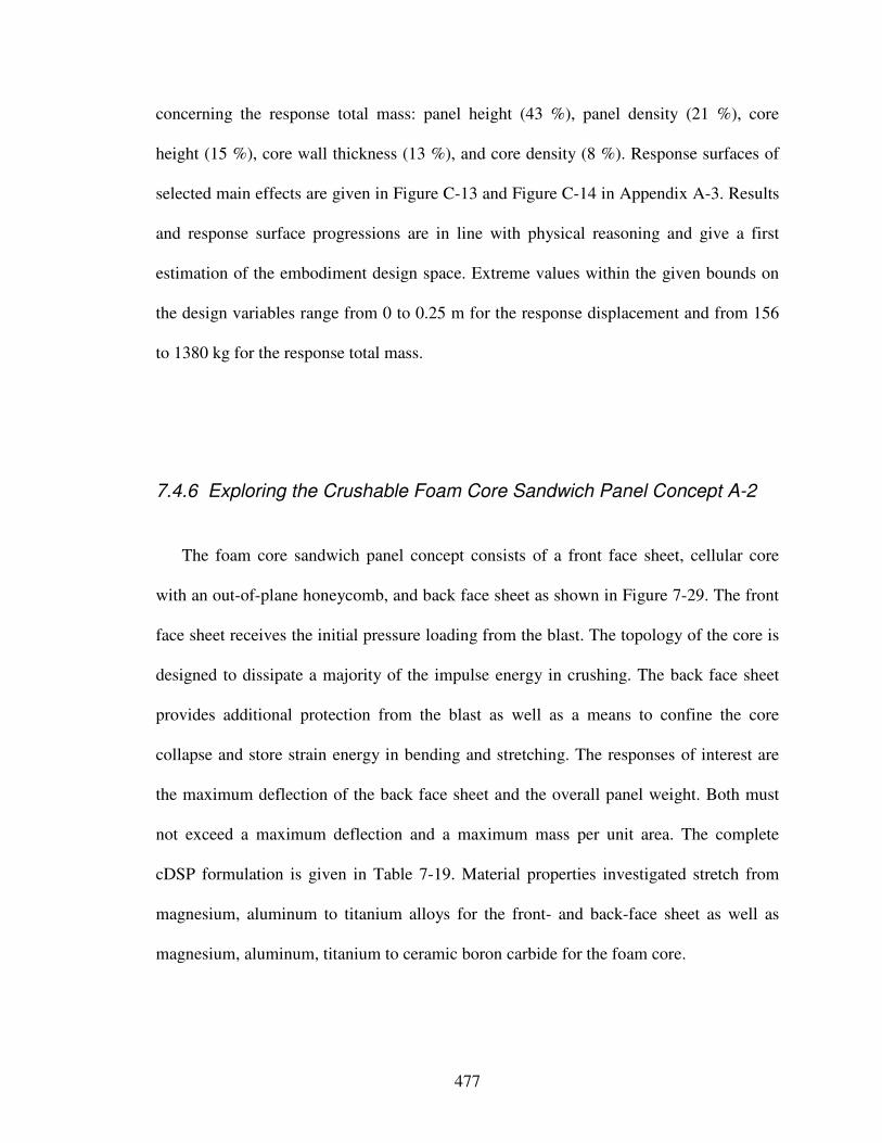
477
concerning the response total mass: panel height (43 %), panel density (21 %), core
height (15 %), core wall thickness (13 %), and core density (8 %). Response surfaces of
selected main effects are given in Figure C-13 and Figure C-14 in Appendix A-3. Results
and response surface progressions are in line with physical reasoning and give a first
estimation of the embodiment design space. Extreme values within the given bounds on
the design variables range from 0 to 0.25 m for the response displacement and from 156
to 1380 kg for the response total mass.
7.4.6 Exploring the Crushable Foam Core Sandwich Panel Concept A-2
The foam core sandwich panel concept consists of a front face sheet, cellular core
with an out-of-plane honeycomb, and back face sheet as shown in Figure 7-29. The front
face sheet receives the initial pressure loading from the blast. The topology of the core is
designed to dissipate a majority of the impulse energy in crushing. The back face sheet
provides additional protection from the blast as well as a means to confine the core
collapse and store strain energy in bending and stretching. The responses of interest are
the maximum deflection of the back face sheet and the overall panel weight. Both must
not exceed a maximum deflection and a maximum mass per unit area. The complete
cDSP formulation is given in Table 7-19. Material properties investigated stretch from
magnesium, aluminum to titanium alloys for the front- and back-face sheet as well as
magnesium, aluminum, titanium to ceramic boron carbide for the foam core.
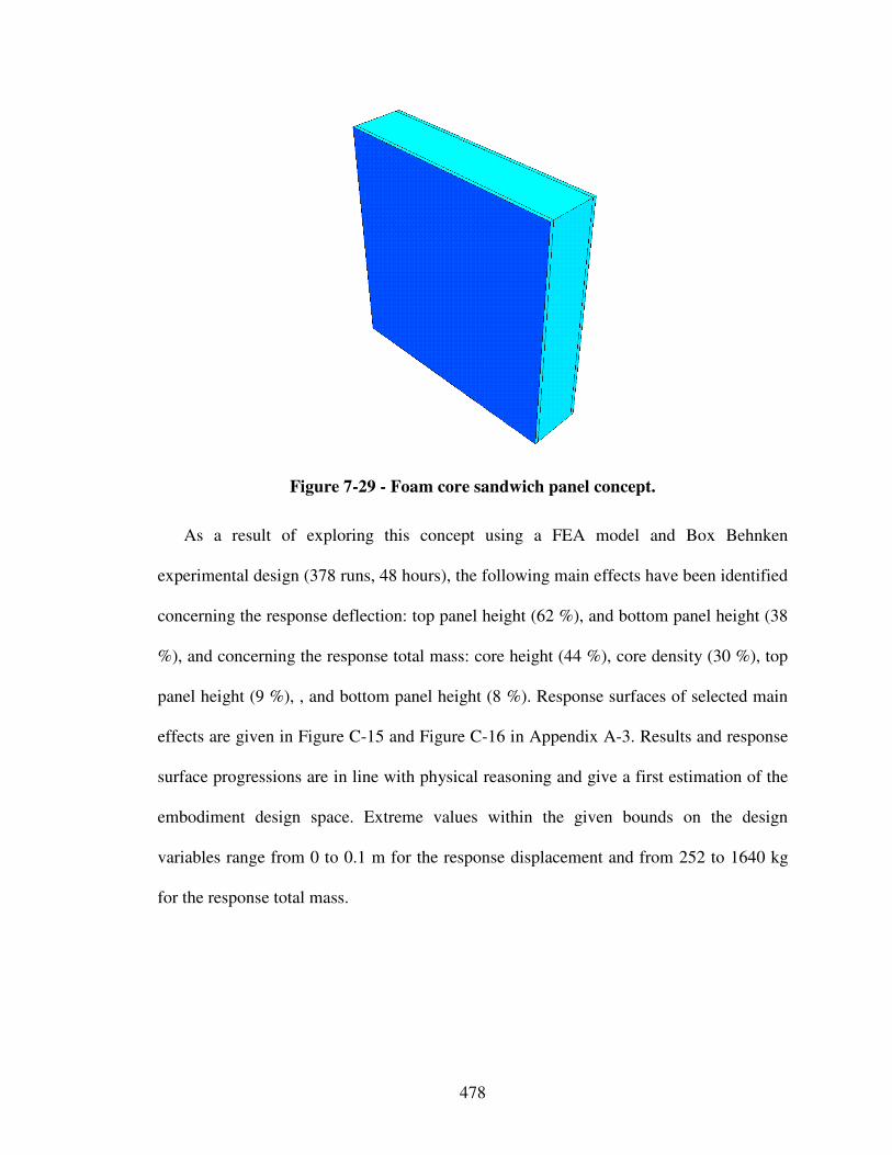
478
Figure 7-29 - Foam core sandwich panel concept.
As a result of exploring this concept using a FEA model and Box Behnken
experimental design (378 runs, 48 hours), the following main effects have been identified
concerning the response deflection: top panel height (62 %), and bottom panel height (38
%), and concerning the response total mass: core height (44 %), core density (30 %), top
panel height (9 %), , and bottom panel height (8 %). Response surfaces of selected main
effects are given in Figure C-15 and Figure C-16 in Appendix A-3. Results and response
surface progressions are in line with physical reasoning and give a first estimation of the
embodiment design space. Extreme values within the given bounds on the design
variables range from 0 to 0.1 m for the response displacement and from 252 to 1640 kg
for the response total mass.
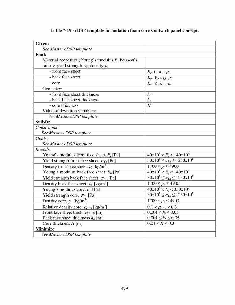
479
Table 7-19 - cDSP template formulation foam core sandwich panel concept.
Given:
See Master cDSP template
Find:
Material properties (Young’s modulus E, Poisson’s
ratio ν, yield strength σY, density ρ):
- front face sheet Ef, νf, σY,f, ρf
- back face sheet Eb, νb, σY,b, ρb
- core Ec, νc, σY,c, ρc
Geometry:
- front face sheet thickness hf
- back face sheet thickness hb
- core thickness H
Value of deviation variables:
See Master cDSP template
Satisfy:
Constraints:
See Master cDSP template
Goals:
See Master cDSP template
Bounds:
Young’s modulus front face sheet, Ef [Pa] 40x109 < Ef < 140x109
Yield strength front face sheet, σY,f [Pa] 30x106 ≤ σY.f ≤ 1250x106
Density front face sheet, ρf [kg/m3] 1700 ≤ ρf ≤ 4900
Young’s modulus back face sheet, Eb [Pa] 40x109 < Ef < 140x109
Yield strength back face sheet, σY,b [Pa] 30x106 ≤ σY.f ≤ 1250x106
Density back face sheet, ρb [kg/m3] 1700 ≤ ρb ≤ 4900
Young’s modulus core, Ec [Pa] 40x109 < Ef < 350x109
Yield strength core, σY,c [Pa] 30x106 ≤ σY.f ≤ 1250x106
Density core, ρc [kg/m3] 1700 ≤ ρc ≤ 4900
Relative density core, ρc,rel [kg/m3] 0.1 < ρc,rel < 0.3
Front face sheet thickness hf [m] 0.001 ≤ hf ≤ 0.05
Back face sheet thickness hb [m] 0.001 ≤ hb ≤ 0.05
Core thickness H [m] 0.01 ≤ H ≤ 0.3
Minimize:
See Master cDSP template
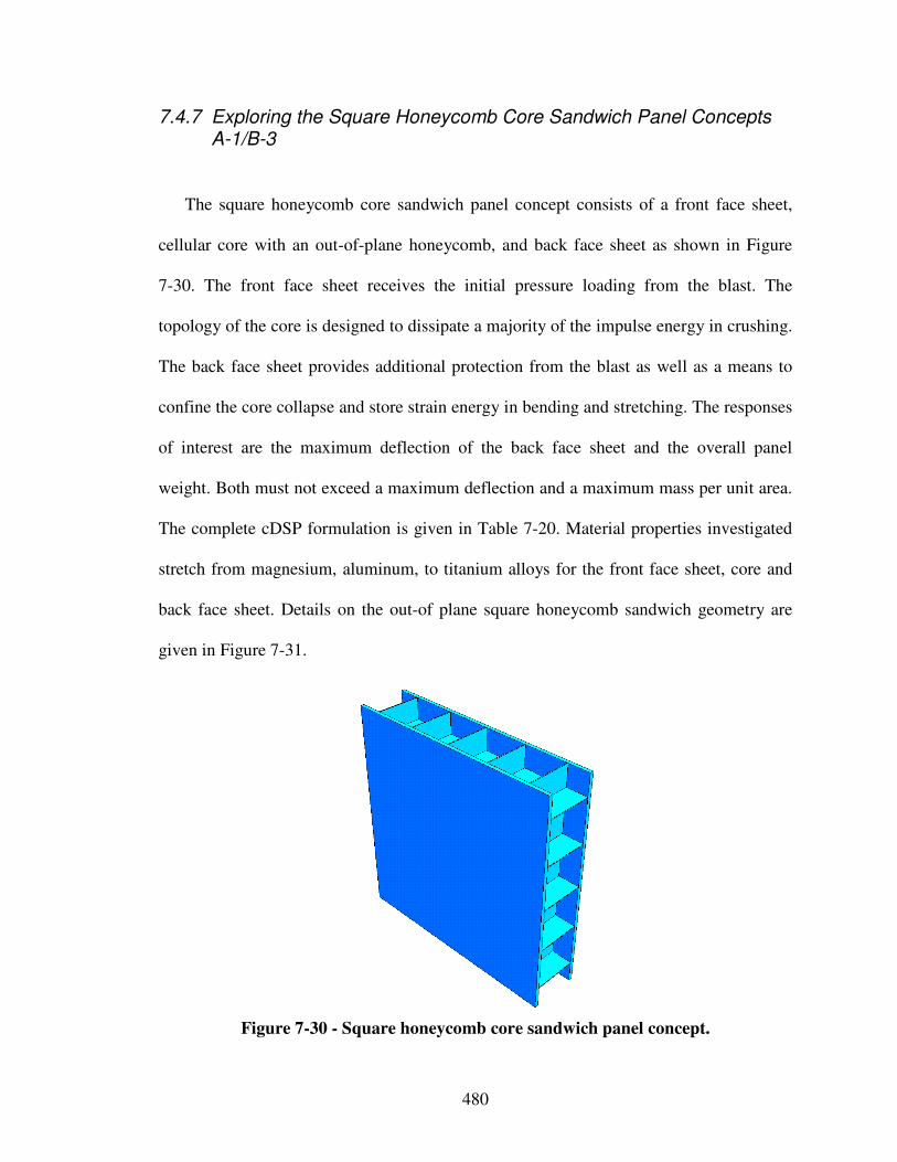
480
7.4.7 Exploring the Square Honeycomb Core Sandwich Panel Concepts A-1/B-3
The square honeycomb core sandwich panel concept consists of a front face sheet,
cellular core with an out-of-plane honeycomb, and back face sheet as shown in Figure
7-30. The front face sheet receives the initial pressure loading from the blast. The
topology of the core is designed to dissipate a majority of the impulse energy in crushing.
The back face sheet provides additional protection from the blast as well as a means to
confine the core collapse and store strain energy in bending and stretching. The responses
of interest are the maximum deflection of the back face sheet and the overall panel
weight. Both must not exceed a maximum deflection and a maximum mass per unit area.
The complete cDSP formulation is given in Table 7-20. Material properties investigated
stretch from magnesium, aluminum, to titanium alloys for the front face sheet, core and
back face sheet. Details on the out-of plane square honeycomb sandwich geometry are
given in Figure 7-31.
Figure 7-30 - Square honeycomb core sandwich panel concept.
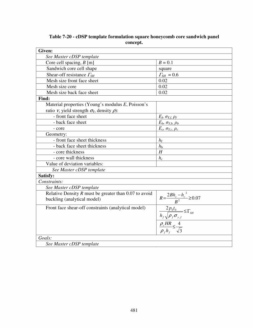
481
Table 7-20 - cDSP template formulation square honeycomb core sandwich panel
concept.
Given:
See Master cDSP template
Core cell spacing, B [m] B = 0.1
Sandwich core cell shape square
Shear-off resistance ΓSH ΓSH = 0.6
Mesh size front face sheet 0.02
Mesh size core 0.02
Mesh size back face sheet 0.02
Find:
Material properties (Young’s modulus E, Poisson’s
ratio ν, yield strength σY, density ρ):
- front face sheet Ef, σY,f, ρf
- back face sheet Eb, σY,b, ρb
- core Ec, σY,c, ρc
Geometry:
- front face sheet thickness hf
- back face sheet thickness hb
- core thickness H
- core wall thickness hc
Value of deviation variables:
See Master cDSP template
Satisfy:
Constraints:
See Master cDSP template
Relative Density R must be greater than 0.07 to avoid buckling (analytical model) 07.0
22
2
≥−
=B
hBhR cc
SH
fyffh
tpΓ≤
,
002
σρ
Front face shear-off constraints (analytical model)
3
4≤
ff
c
h
HR
ρ
ρ
Goals:
See Master cDSP template
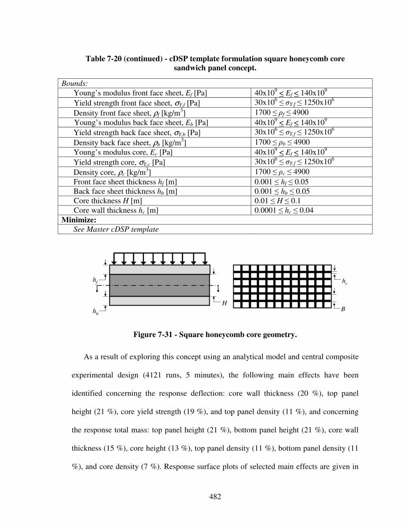
482
Table 7-20 (continued) - cDSP template formulation square honeycomb core
sandwich panel concept.
Bounds:
Young’s modulus front face sheet, Ef [Pa] 40x109 < Ef < 140x109
Yield strength front face sheet, σY,f [Pa] 30x106 ≤ σY.f ≤ 1250x106
Density front face sheet, ρf [kg/m3] 1700 ≤ ρf ≤ 4900
Young’s modulus back face sheet, Eb [Pa] 40x109 < Ef < 140x109
Yield strength back face sheet, σY,b [Pa] 30x106 ≤ σY.f ≤ 1250x106
Density back face sheet, ρb [kg/m3] 1700 ≤ ρb ≤ 4900
Young’s modulus core, Ec [Pa] 40x109 < Ef < 140x109
Yield strength core, σY,c [Pa] 30x106 ≤ σY.f ≤ 1250x106
Density core, ρc [kg/m3] 1700 ≤ ρc ≤ 4900
Front face sheet thickness hf [m] 0.001 ≤ hf ≤ 0.05
Back face sheet thickness hb [m] 0.001 ≤ hb ≤ 0.05
Core thickness H [m] 0.01 ≤ H ≤ 0.1
Core wall thickness hc [m] 0.0001 ≤ hc ≤ 0.04
Minimize:
See Master cDSP template
Figure 7-31 - Square honeycomb core geometry.
As a result of exploring this concept using an analytical model and central composite
experimental design (4121 runs, 5 minutes), the following main effects have been
identified concerning the response deflection: core wall thickness (20 %), top panel
height (21 %), core yield strength (19 %), and top panel density (11 %), and concerning
the response total mass: top panel height (21 %), bottom panel height (21 %), core wall
thickness (15 %), core height (13 %), top panel density (11 %), bottom panel density (11
%), and core density (7 %). Response surface plots of selected main effects are given in
hc
B
hf
hb
H
483
Figure C-17 and Figure C-18 in Appendix A-3. Results and response surface
progressions are in line with physical reasoning and give a first estimation of the
embodiment design space. Extreme values within the given bounds on the design
variables range from 0 to 9.7 m for the response displacement and from 7 to 800 kg for
the response total mass. Since results of exploring the concept with this analytical model,
described in greater detail in Section 7.4.1, do not seem to be in line with previous
predictions and results of other concepts above, the out-of-plane square honeycomb
sandwich concept is also explored using a more computationally intense FEA model as
described in the following. However, embodiment design-process will be discussed in
Section 7.6.
As a result of exploring this concept using a FEA model and Box Behnken
experimental design (378 runs, 72 hours), the following main effects have been identified
concerning the response deflection: bottom panel height (51 %), and top panel height (49
%), and concerning the response total mass: bottom panel height (35 %), top panel height
(15 %), top panel density (11 %), core wall thickness (11 %), core height (10 %), bottom
panel density (9 %), and core density (9 %). Response surface plots of selected main
effects are given in Figure C-19 and Figure C-20 in Appendix A-3. Results and response
surface progressions are in line with physical reasoning and give a first estimation of the
embodiment design space. Extreme values within the given bounds on the design
variables range from 0 to 0.05 m for the response displacement and from 64 to 1080 kg
for the response total mass.
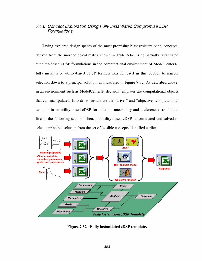
484
7.4.8 Concept Exploration Using Fully Instantiated Compromise DSP Formulations
Having explored design spaces of the most promising blast resistant panel concepts,
derived from the morphological matrix shown in Table 7-14, using partially instantiated
template-based cDSP formulations in the computational environment of ModelCenter®,
fully instantiated utility-based cDSP formulations are used in this Section to narrow
selection down to a principal solution, as illustrated in Figure 7-32. As described above,
in an environment such as ModelCenter®, decision templates are computational objects
that can manipulated. In order to instantiate the “driver” and “objective” computational
template in an utility-based cDSP formulation, uncertainty and preferences are elicited
first in the following section. Then, the utility-based cDSP is formulated and solved to
select a principal solution from the set of feasible concepts identified earlier.
Goals
Preferences
Variables
Parameters
Constraints
Response
Objective
Analysis
Driver
Fully Instantiated cDSP Template
Driver
BRP analysis model
Response
core
front
backσ σ
εε
Blast
A
t
Other constraints, variables, parameters, goals, and preferences
Material properties
Objective function
Figure 7-32 - Fully instantiated cDSP template.
485
7.4.9 Utility-Based Fully Instantiated Compromise DSP Formulation
In order to fully instantiate a utility-based cDSP template, conditional utilities for
individual attributes must be elicited. Also, a subjective probability function with respect
to the most uncertain event – blast loading – is determined. Other uncertainties, such as
material property uncertainties, are neglected. However, in the context of designing blast
resistant panels for the reactive material containment system, design goals are to
minimize the following attributes:
• mean of deflection,
• variance of deflection,
• mean of total mass, and
• variance of total mass,
based on the blast loading uncertainty and preferences for individual attributes elicited in
the following.
The question “how can multi-attribute utility functions be constructed?” is answered
by Keeney and Raiffa [319] by developing a method that consists of two stages – a)
assessment of utility function for each attribute and b) combination of individual utility
functions into a multi-attribute utility function that can be used to evaluate outcomes of
alternatives in terms of all the attributes that characterize them. The details of
determining multi-attribute utility functions are not discussed in this dissertation.
Interested readers should refer to Keeney and Raiffa [319]. Utility functions are used in
this dissertation for modeling designers’ preferences because utility theory is a domain
independent approach used to facilitate design decision making by evaluating preferences
under conditions of risk and uncertainty. The focus in the dissertation is on utilizing the
486
utility functions for making decisions and not on eliciting the utility functions, which is a
separate research field in itself.
The decision criterion used in the formulation of the utility-based cDSP is to select
the point in design space that minimizes the objective function which represents deviation
from overall maximum utility. The objective function can also be formulated in other
forms such as weighted sum of minimum and maximum possible values, etc. However,
selection of the decision criterion (i.e., the objective function) is dependent on the
problem at hand and should be chosen by the designer. Although the results will be
different for different decision criteria, the general principles and the discussion that
follows remain valid and are independent of the decision criterion chosen.
In order to elicit preferences for the individual attributes, one must verify their mutual
utility independence. Only then can a utility-based compromise DSP be formulated.
Utility independence means that the conditional preferences for elicitation questions on x
given a value of attribute y do not depend on the value of y. In the context of blast
resistant panels this means that preferences for deflection should be independent of the
values for total mass, and preferences for total mass should be independent of the value
for deflection. Based on the assumptions stated above, this is in fact the case. Therefore, a
utility-based compromise DSP can be formulated.
Eliciting preferences for individual attributes is based on asking the following
questions:
i) What is the worst and best case, and
ii) What are the certainty equivalents, using a repeated bisection approach for
intervals?
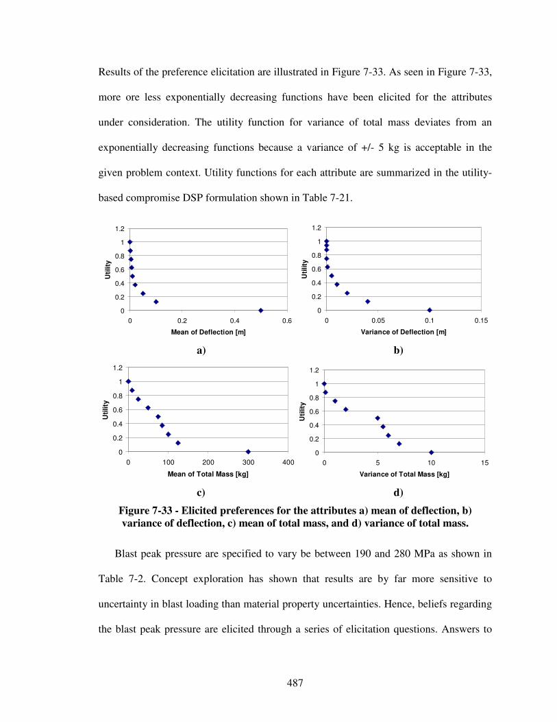
487
Results of the preference elicitation are illustrated in Figure 7-33. As seen in Figure 7-33,
more ore less exponentially decreasing functions have been elicited for the attributes
under consideration. The utility function for variance of total mass deviates from an
exponentially decreasing functions because a variance of +/- 5 kg is acceptable in the
given problem context. Utility functions for each attribute are summarized in the utility-
based compromise DSP formulation shown in Table 7-21.
0
0.2
0.4
0.6
0.8
1
1.2
0 0.2 0.4 0.6
Mean of Deflection [m]
Uti
lity
0
0.2
0.4
0.6
0.8
1
1.2
0 0.05 0.1 0.15
Variance of Deflection [m]
Uti
lity
a) b)
0
0.2
0.4
0.6
0.8
1
1.2
0 100 200 300 400
Mean of Total Mass [kg]
Uti
lity
0
0.2
0.4
0.6
0.8
1
1.2
0 5 10 15
Variance of Total Mass [kg]
Uti
lity
c) d)
Figure 7-33 - Elicited preferences for the attributes a) mean of deflection, b)
variance of deflection, c) mean of total mass, and d) variance of total mass.
Blast peak pressure are specified to vary be between 190 and 280 MPa as shown in
Table 7-2. Concept exploration has shown that results are by far more sensitive to
uncertainty in blast loading than material property uncertainties. Hence, beliefs regarding
the blast peak pressure are elicited through a series of elicitation questions. Answers to
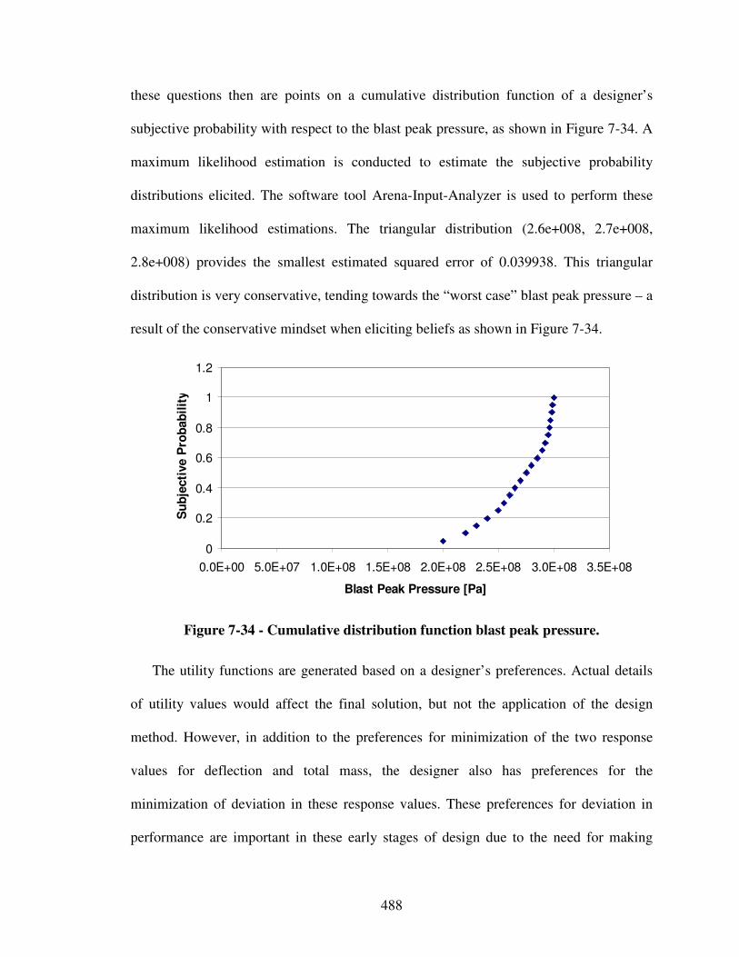
488
these questions then are points on a cumulative distribution function of a designer’s
subjective probability with respect to the blast peak pressure, as shown in Figure 7-34. A
maximum likelihood estimation is conducted to estimate the subjective probability
distributions elicited. The software tool Arena-Input-Analyzer is used to perform these
maximum likelihood estimations. The triangular distribution (2.6e+008, 2.7e+008,
2.8e+008) provides the smallest estimated squared error of 0.039938. This triangular
distribution is very conservative, tending towards the “worst case” blast peak pressure – a
result of the conservative mindset when eliciting beliefs as shown in Figure 7-34.
0
0.2
0.4
0.6
0.8
1
1.2
0.0E+00 5.0E+07 1.0E+08 1.5E+08 2.0E+08 2.5E+08 3.0E+08 3.5E+08
Blast Peak Pressure [Pa]
Su
bje
cti
ve P
rob
ab
ilit
y
Figure 7-34 - Cumulative distribution function blast peak pressure.
The utility functions are generated based on a designer’s preferences. Actual details
of utility values would affect the final solution, but not the application of the design
method. However, in addition to the preferences for minimization of the two response
values for deflection and total mass, the designer also has preferences for the
minimization of deviation in these response values. These preferences for deviation in
performance are important in these early stages of design due to the need for making
489
decisions that are robust to variation, as discussed in Section 2.4.3. The variation in
performance can be due to various factors such as inherent randomness in material
properties, imprecision in simulation models, etc. In this work however, only uncertainty
with respect to the most uncertain event – blast loading – is considered. Hence, based on
the uncertainty and preference elicitation of utility independent attributes the utility-based
cDSP is formulated and presented in Table 7-21.
The utility-based cDSP formulation specified in Table 7-21 is instantiated in
ModelCenter for each of the concepts explored in Section 7.4. Results for equal attribute
weightings are given in Table 7-22. Shortcomings in material density of simple
monolithic material panels have been considered by exploring shaped components that
maximize load capacity, such as stiffened “waffle” panels. Other topologies that have
been explored to maximize load capacity at yet lighter weights are foam and honeycomb
panels. Depending on the application, these may also impart functionalities in addition to
load-bearing (whereupon the extra weight of an additional component normally needed to
provide that function can be saved).
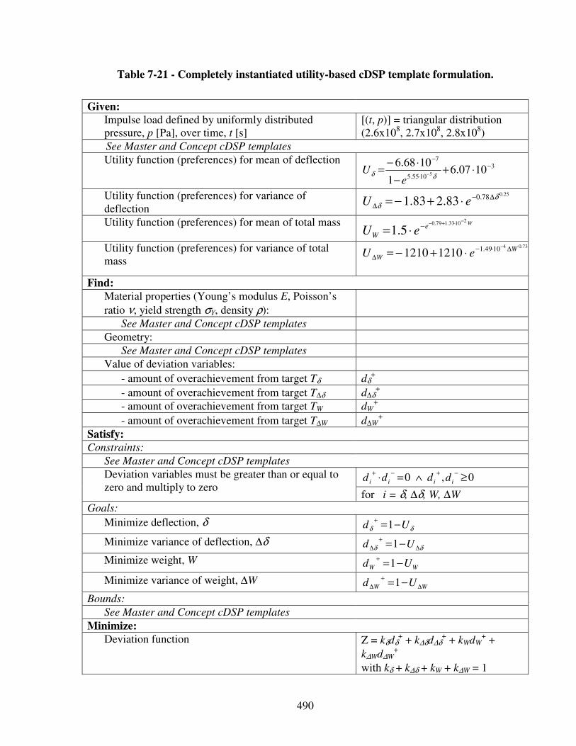
490
Table 7-21 - Completely instantiated utility-based cDSP template formulation.
Given:
Impulse load defined by uniformly distributed pressure, p [Pa], over time, t [s]
[(t, p)] = triangular distribution (2.6x10⁸, 2.7x10⁸, 2.8x10⁸)
See Master and Concept cDSP templates
Utility function (preferences) for mean of deflection 3
1055.5
7
1007.61
1068.65
−
⋅
−
⋅+−
⋅−=
− δδe
U
Utility function (preferences) for variance of deflection
25.078.083.283.1 δδ
∆−∆ ⋅+−= eU
Utility function (preferences) for mean of total mass We
W eU21033.179.0
5.1−⋅+−−⋅=
Utility function (preferences) for variance of total mass
73.041049.112101210 W
W eU∆⋅−
∆
−
⋅+−=
Find:
Material properties (Young’s modulus E, Poisson’s
ratio ν, yield strength σY, density ρ):
See Master and Concept cDSP templates
Geometry:
See Master and Concept cDSP templates
Value of deviation variables:
- amount of overachievement from target Tδ dδ+
- amount of overachievement from target T∆δ d∆δ+
- amount of overachievement from target TW dW+
- amount of overachievement from target T∆W d∆W+
Satisfy:
Constraints:
See Master and Concept cDSP templates
0,0 ≥∧=⋅−+−+
iiii dddd Deviation variables must be greater than or equal to zero and multiply to zero
for i = δ, ∆δ, W, ∆W
Goals:
Minimize deflection, δ δδ Ud −=
+1
Minimize variance of deflection, ∆δ δδ ∆
+
∆ −= Ud 1
Minimize weight, W WW Ud −=
+1
Minimize variance of weight, ∆W WW Ud ∆
+
∆ −=1
Bounds:
See Master and Concept cDSP templates
Minimize:
Deviation function Z = kδdδ+ + k∆δd∆δ
+ + kWdW+ +
k∆Wd∆W+
with kδ + k∆δ + kW + k∆W = 1
491
From the concept exploration results presented in Table 7-22 it is shown that out-of-
plane honeycomb core sandwich panels provide less than the deflection specified in the
requirements list shown in Table 7-2 at the lowest total mass of all concepts explored.
These results are in line with previous investigations stating that sandwich structures
outperform monolithic solids of equivalent weight in terms of deflection resistance in the
bending-dominated domain, i.e., when the deflections are small relative to the support
span [191]. However, in these investigations the benefits have been shown to diminish at
large deflections, as the response becomes stretching dominated. The benefits of
sandwich construction hence depend on the core topology. Core designs that afford
simultaneous crushing and stretching resistance, such as out-of-plane honeycomb cores,
are preferred to those that are bending dominated, such as foam cores. Additional benefits
of sandwich construction derive from fluid/structure interaction effects [210, 751].
Based on the preceding selection procedures, concept exploration results,
comparisons to previous investigations, and given performance requirements, the solution
containing the out-of-plane square honeycomb core sandwich is selected as the principal
solution.
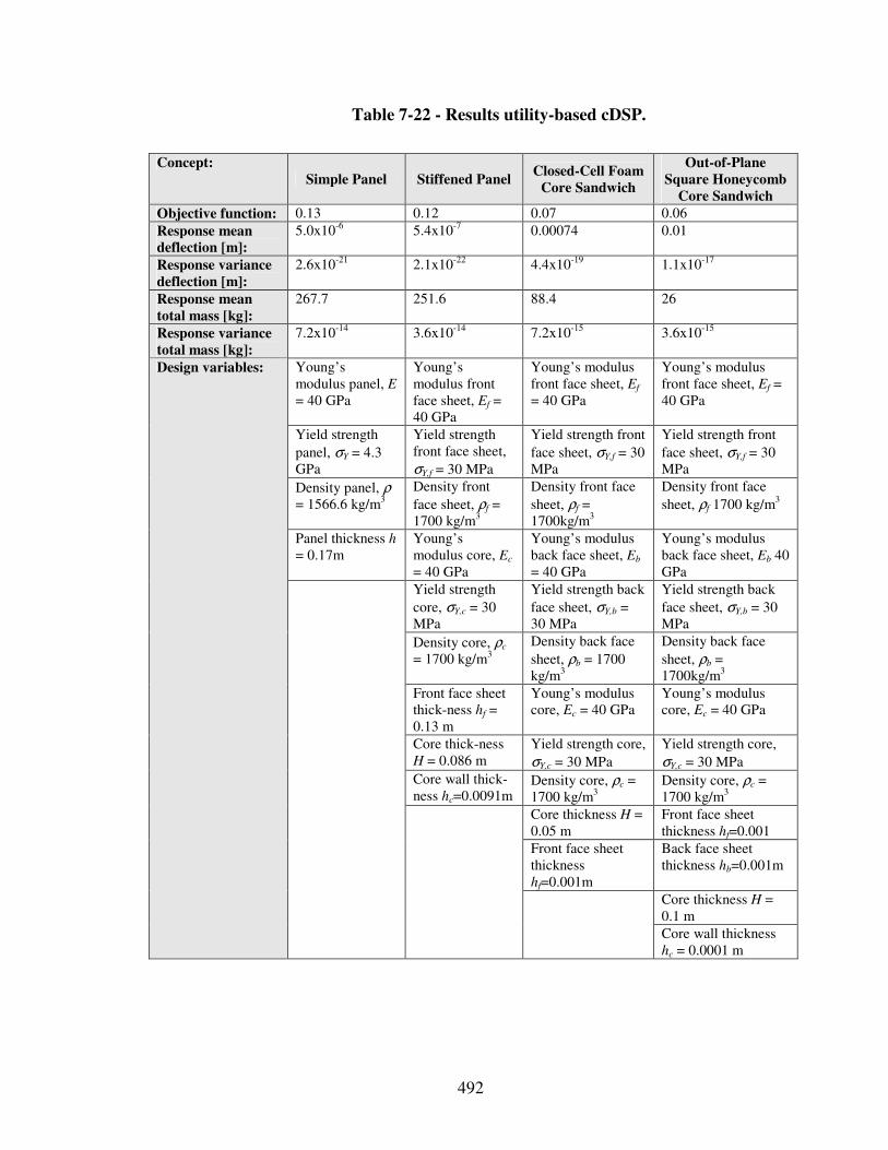
492
Table 7-22 - Results utility-based cDSP.
Concept:
Simple Panel Stiffened Panel Closed-Cell Foam
Core Sandwich
Out-of-Plane
Square Honeycomb
Core Sandwich
Objective function: 0.13 0.12 0.07 0.06
Response mean
deflection [m]:
5.0x10⁻⁶ 5.4x10⁻⁷ 0.00074 0.01
Response variance
deflection [m]:
2.6x10⁻²¹ 2.1x10⁻²² 4.4x10⁻¹⁹ 1.1x10⁻¹⁷
Response mean
total mass [kg]:
267.7 251.6 88.4 26
Response variance
total mass [kg]:
7.2x10⁻¹⁴ 3.6x10⁻¹⁴ 7.2x10⁻¹⁵ 3.6x10⁻¹⁵
Young’s modulus panel, E
= 40 GPa
Young’s modulus front face sheet, Ef = 40 GPa
Young’s modulus front face sheet, Ef
= 40 GPa
Young’s modulus front face sheet, Ef = 40 GPa
Yield strength
panel, σY = 4.3 GPa
Yield strength front face sheet,
σY,f = 30 MPa
Yield strength front
face sheet, σY,f = 30 MPa
Yield strength front
face sheet, σY,f = 30 MPa
Density panel, ρ
= 1566.6 kg/m3
Density front
face sheet, ρf = 1700 kg/m3
Density front face
sheet, ρf = 1700kg/m3
Density front face
sheet, ρf 1700 kg/m3
Panel thickness h = 0.17m
Young’s modulus core, Ec
= 40 GPa
Young’s modulus back face sheet, Eb = 40 GPa
Young’s modulus back face sheet, Eb 40 GPa
Yield strength
core, σY,c = 30 MPa
Yield strength back
face sheet, σY,b = 30 MPa
Yield strength back
face sheet, σY,b = 30 MPa
Density core, ρc
= 1700 kg/m3
Density back face
sheet, ρb = 1700 kg/m3
Density back face
sheet, ρb = 1700kg/m3
Front face sheet thick-ness hf = 0.13 m
Young’s modulus core, Ec = 40 GPa
Young’s modulus core, Ec = 40 GPa
Core thick-ness H = 0.086 m
Yield strength core,
σY,c = 30 MPa
Yield strength core,
σY,c = 30 MPa
Core wall thick-ness hc=0.0091m
Density core, ρc = 1700 kg/m3
Density core, ρc = 1700 kg/m3
Core thickness H = 0.05 m
Front face sheet thickness hf=0.001
Front face sheet thickness hf=0.001m
Back face sheet thickness hb=0.001m
Core thickness H = 0.1 m
Design variables:
Core wall thickness hc = 0.0001 m
493
7.5 Step 2 – Concept Exploration and Selection
7.5.1 Concept Selection
Based on the preceding sDSP selection procedures, the cDSP concept exploration
results shown in Table 7-22, and given performance requirements, the solution containing
the out-of-plane square honeycomb core sandwich is selected as the principal solution.
As illustrated in Figure 7-35, this principal solution consists of i) a reactive material,
fulfilling the function of storing energy for usage during an energetic application, which
is enclosed by a containment system that in turn consists of ii) panels, fulfilling the
function of transforming/changing and dissipating energy, connected to iii) out-of-plane
square honeycomb cores, fulfilling the function of dissipating energy, and iv) panels,
fulfilling the function of storing energy. This principal is thus further embodied in the
following.
Since the out-of-plane honeycomb sandwich panel concept finite element analysis is
too computationally expensive for rapid concept exploration, it is simplified by focusing
on main effects. In other words, the number of design variable is reduced based on the
following main effect analysis. Using a 16th fractional factorial experimental design
(1024 runs, 240 hours), the main effect analysis reviewed in Section 7.4.7 is refined, as
illustrated in Figure 7-36. As a result, the following main effects have been identified
concerning the response deflection: top panel height (22 %), bottom panel height (21 %),
core wall thickness (17 %), core height (11 %), etc., and concerning the response total
mass: bottom panel height (35 %), top panel height (13 %), core height (12 %), etc.
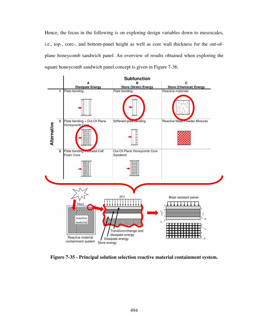
494
Hence, the focus in the following is on exploring design variables down to mesoscales,
i.e., top-, core-, and bottom-panel height as well as core wall thickness for the out-of-
plane honeycomb sandwich panel. An overview of results obtained when exploring the
square honeycomb sandwich panel concept is given in Figure 7-36.
reactive
material
blast
p(t)
Transform/change and dissipate energy
Dissipate energyStore energy
hf
hb
H
hc
B Reactive materialcontainment system
Blast resistant panel
A B C
Dissipate Energy Store (Strain) Energy Store (Chemical) Energy
1 Plate bending Plate bending Reactive materials
2 Plate bending + Out-Of-Plane
Honeycomb Core
Stiffened plate bending Reactive Metal Powder Mixtures
3 Plate bending + Closed-Cell
Foam Core
Out-Of-Plane Honeycomb Core
Sandwich
Alt
ern
ati
ve
Subfunction
Figure 7-35 - Principal solution selection reactive material containment system.
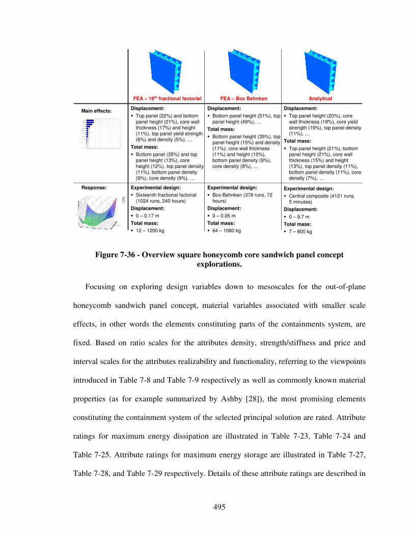
495
Displacement:
� Top panel (22%) and bottom
panel height (21%), core wall thickness (17%) and height (11%), top panel yield strength (6%) and density (5%), …
Total mass:
� Bottom panel (35%) and top panel height (13%), core height (12%), top panel density (11%), bottom panel density (9%), core density (9%), …
Experimental design:
� Sixteenth fractional factorial (1024 runs, 240 hours)
Displacement:
� 0 – 0.17 m
Total mass:
� 12 – 1200 kg
Response:
Main effects:
FEA – 16th fractional factorial FEA – Box Behnken Analytical
Displacement:
� Bottom panel height (51%), top
panel height (49%), …
Total mass:
� Bottom panel height (35%), top panel height (15%) and density (11%), core wall thickness (11%) and height (10%), bottom panel density (9%), core density (9%), …
Displacement:
� Top panel height (20%), core
wall thickness (19%), core yield strength (19%), top panel density (11%), …
Total mass:
� Top panel height (21%), bottom panel height (21%), core wall thickness (15%) and height (13%), top panel density (11%), bottom panel density (11%), core density (7%), …
Experimental design:
� Box-Behnken (378 runs, 72 hours)
Displacement:
� 0 – 0.05 m
Total mass:
� 64 – 1080 kg
Experimental design:
� Central composite (4121 runs, 5 minutes)
Displacement:
� 0 – 9.7 m
Total mass:
� 7 – 800 kg
Figure 7-36 - Overview square honeycomb core sandwich panel concept
explorations.
Focusing on exploring design variables down to mesoscales for the out-of-plane
honeycomb sandwich panel concept, material variables associated with smaller scale
effects, in other words the elements constituting parts of the containments system, are
fixed. Based on ratio scales for the attributes density, strength/stiffness and price and
interval scales for the attributes realizability and functionality, referring to the viewpoints
introduced in Table 7-8 and Table 7-9 respectively as well as commonly known material
properties (as for example summarized by Ashby [28]), the most promising elements
constituting the containment system of the selected principal solution are rated. Attribute
ratings for maximum energy dissipation are illustrated in Table 7-23, Table 7-24 and
Table 7-25. Attribute ratings for maximum energy storage are illustrated in Table 7-27,
Table 7-28, and Table 7-29 respectively. Details of these attribute ratings are described in
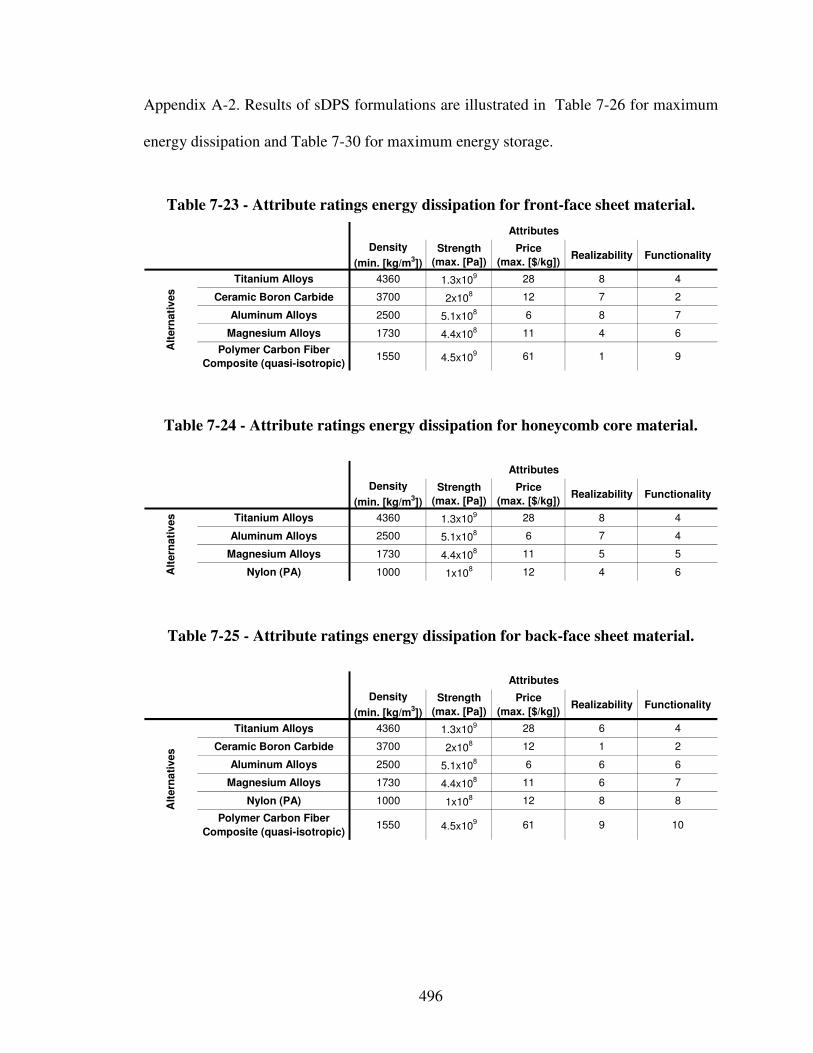
496
Appendix A-2. Results of sDPS formulations are illustrated in Table 7-26 for maximum
energy dissipation and Table 7-30 for maximum energy storage.
Table 7-23 - Attribute ratings energy dissipation for front-face sheet material.
Density
(min. [kg/m3])
Strength
(max. [Pa])
Price
(max. [$/kg])Realizability Functionality
Titanium Alloys 4360 1.3x10⁹ 28 8 4
Ceramic Boron Carbide 3700 2x10⁸ 12 7 2
Aluminum Alloys 2500 5.1x10⁸ 6 8 7
Magnesium Alloys 1730 4.4x10⁸ 11 4 6
Polymer Carbon Fiber
Composite (quasi-isotropic)1550 4.5x10
9 61 1 9
Attributes
Alt
ern
ati
ves
Table 7-24 - Attribute ratings energy dissipation for honeycomb core material.
Density
(min. [kg/m3])
Strength
(max. [Pa])
Price
(max. [$/kg])Realizability Functionality
Titanium Alloys 4360 1.3x10⁹ 28 8 4
Aluminum Alloys 2500 5.1x10⁸ 6 7 4
Magnesium Alloys 1730 4.4x10⁸ 11 5 5
Nylon (PA) 1000 1x10⁸ 12 4 6
Attributes
Alt
ern
ati
ves
Table 7-25 - Attribute ratings energy dissipation for back-face sheet material.
Density
(min. [kg/m3])
Strength
(max. [Pa])
Price
(max. [$/kg])Realizability Functionality
Titanium Alloys 4360 1.3x10⁹ 28 6 4
Ceramic Boron Carbide 3700 2x10⁸ 12 1 2
Aluminum Alloys 2500 5.1x10⁸ 6 6 6
Magnesium Alloys 1730 4.4x10⁸ 11 6 7
Nylon (PA) 1000 1x10⁸ 12 8 8
Polymer Carbon Fiber
Composite (quasi-isotropic)1550 4.5x10
9 61 9 10
Attributes
Alt
ern
ati
ves
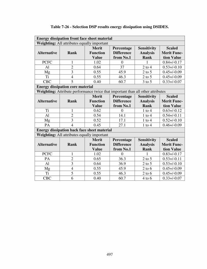
497
Table 7-26 - Selection DSP results energy dissipation using DSIDES.
Energy dissipation front face sheet material
Weighting: All attributes equally important
Alternative Rank
Merit
Function
Value
Percentage
Difference
from No.1
Sensitivity
Analysis
Rank
Scaled
Merit Func-
tion Value
PCFC 1 1.02 0 1 0.84+/-0.17
Al 2 0.64 37 2 to 4 0.53+/-0.10
Mg 3 0.55 45.9 2 to 5 0.45+/-0.09
Ti 4 0.55 46.3 2 to 5 0.45+/-0.09
CBC 5 0.40 60.7 3 to 5 0.33+/-0.07
Energy dissipation core material Weighting: Attribute performance twice that important than all other attributes
Alternative Rank
Merit
Function
Value
Percentage
Difference
from No.1
Sensitivity
Analysis
Rank
Scaled
Merit Func-
tion Value
Ti 1 0.62 0 1 to 4 0.63+/-0.12
Al 2 0.54 14.1 1 to 4 0.54+/-0.11
Mg 3 0.52 17.1 1 to 4 0.52+/-0.10
PA 4 0.45 27.1 1 to 4 0.46+/-0.09
Energy dissipation back face sheet material Weighting: All attributes equally important
Alternative Rank
Merit
Function
Value
Percentage
Difference
from No.1
Sensitivity
Analysis
Rank
Scaled
Merit Func-
tion Value
PCFC 1 1.02 0 1 0.83+/-0.17
PA 2 0.65 36.3 2 to 5 0.53+/-0.11
Al 3 0.64 36.9 2 to 5 0.53+/-0.10
Mg 4 0.55 45.9 2 to 6 0.45+/-0.09
Ti 5 0.55 46.3 2 to 6 0.45+/-0.09
CBC 6 0.40 60.7 4 to 6 0.33+/-0.07
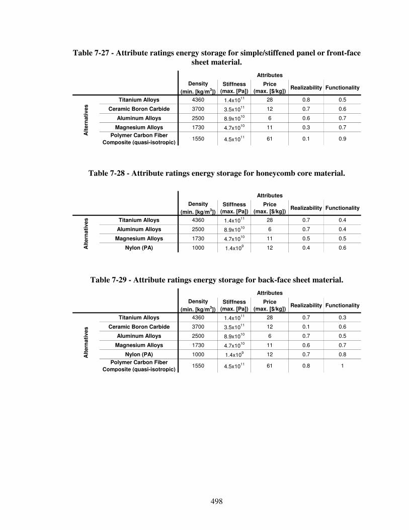
498
Table 7-27 - Attribute ratings energy storage for simple/stiffened panel or front-face
sheet material.
Density
(min. [kg/m3])
Stiffness
(max. [Pa])
Price
(max. [$/kg])Realizability Functionality
Titanium Alloys 4360 1.4x10¹¹ 28 0.8 0.5
Ceramic Boron Carbide 3700 3.5x10¹¹ 12 0.7 0.6
Aluminum Alloys 2500 8.9x10¹⁰ 6 0.6 0.7
Magnesium Alloys 1730 4.7x10¹⁰ 11 0.3 0.7
Polymer Carbon Fiber
Composite (quasi-isotropic)1550 4.5x10
11 61 0.1 0.9
Attributes
Alt
ern
ati
ves
Table 7-28 - Attribute ratings energy storage for honeycomb core material.
Density
(min. [kg/m3])
Stiffness
(max. [Pa])
Price
(max. [$/kg])Realizability Functionality
Titanium Alloys 4360 1.4x10¹¹ 28 0.7 0.4
Aluminum Alloys 2500 8.9x10¹⁰ 6 0.7 0.4
Magnesium Alloys 1730 4.7x10¹⁰ 11 0.5 0.5
Nylon (PA) 1000 1.4x10⁹ 12 0.4 0.6
Attributes
Alt
ern
ati
ve
s
Table 7-29 - Attribute ratings energy storage for back-face sheet material.
Density
(min. [kg/m3])
Stiffness
(max. [Pa])
Price
(max. [$/kg])Realizability Functionality
Titanium Alloys 4360 1.4x10¹¹ 28 0.7 0.3
Ceramic Boron Carbide 3700 3.5x10¹¹ 12 0.1 0.6
Aluminum Alloys 2500 8.9x10¹⁰ 6 0.7 0.5
Magnesium Alloys 1730 4.7x10¹⁰ 11 0.6 0.7
Nylon (PA) 1000 1.4x10⁹ 12 0.7 0.8
Polymer Carbon Fiber
Composite (quasi-isotropic)1550 4.5x10
11 61 0.8 1
Attributes
Alt
ern
ati
ve
s
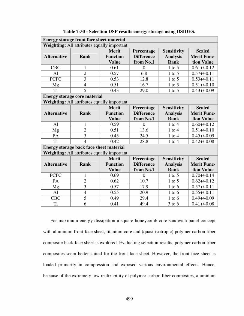
499
Table 7-30 - Selection DSP results energy storage using DSIDES.
Energy storage front face sheet material
Weighting: All attributes equally important
Alternative Rank
Merit
Function
Value
Percentage
Difference
from No.1
Sensitivity
Analysis
Rank
Scaled
Merit Func-
tion Value
CBC 1 0.61 0 1 to 5 0.61+/-0.12
Al 2 0.57 6.8 1 to 5 0.57+/-0.11
PCFC 3 0.53 12.8 1 to 5 0.53+/-0.11
Mg 4 0.51 16.7 1 to 5 0.51+/-0.10
Ti 5 0.43 29.0 1 to 5 0.43+/-0.09
Energy storage core material Weighting: All attributes equally important
Alternative Rank
Merit
Function
Value
Percentage
Difference
from No.1
Sensitivity
Analysis
Rank
Scaled
Merit Func-
tion Value
Al 1 0.59 0 1 to 4 0.60+/-0.12
Mg 2 0.51 13.6 1 to 4 0.51+/-0.10
PA 3 0.45 24.5 1 to 4 0.45+/-0.09
Ti 4 0.42 28.8 1 to 4 0.42+/-0.08
Energy storage back face sheet material Weighting: All attributes equally important
Alternative Rank
Merit
Function
Value
Percentage
Difference
from No.1
Sensitivity
Analysis
Rank
Scaled
Merit Func-
tion Value
PCFC 1 0.69 0 1 to 5 0.70+/-0.14
PA 2 0.62 10.7 1 to 5 0.62+/-0.12
Mg 3 0.57 17.9 1 to 6 0.57+/-0.11
Al 4 0.55 20.9 1 to 6 0.55+/-0.11
CBC 5 0.49 29.4 1 to 6 0.49+/-0.09
Ti 6 0.41 49.4 3 to 6 0.41+/-0.08
For maximum energy dissipation a square honeycomb core sandwich panel concept
with aluminum front-face sheet, titanium core and (quasi-isotropic) polymer carbon fiber
composite back-face sheet is explored. Evaluating selection results, polymer carbon fiber
composites seem better suited for the front face sheet. However, the front face sheet is
loaded primarily in compression and exposed various environmental effects. Hence,
because of the extremely low realizability of polymer carbon fiber composites, aluminum
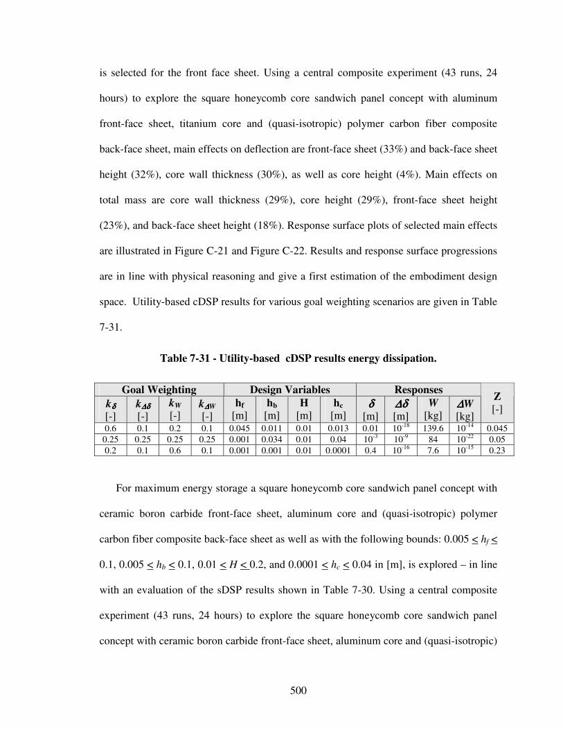
500
is selected for the front face sheet. Using a central composite experiment (43 runs, 24
hours) to explore the square honeycomb core sandwich panel concept with aluminum
front-face sheet, titanium core and (quasi-isotropic) polymer carbon fiber composite
back-face sheet, main effects on deflection are front-face sheet (33%) and back-face sheet
height (32%), core wall thickness (30%), as well as core height (4%). Main effects on
total mass are core wall thickness (29%), core height (29%), front-face sheet height
(23%), and back-face sheet height (18%). Response surface plots of selected main effects
are illustrated in Figure C-21 and Figure C-22. Results and response surface progressions
are in line with physical reasoning and give a first estimation of the embodiment design
space. Utility-based cDSP results for various goal weighting scenarios are given in Table
7-31.
Table 7-31 - Utility-based cDSP results energy dissipation.
Goal Weighting Design Variables Responses
kδδδδ
[-] k∆δ∆δ∆δ∆δ
[-]
kW
[-] k∆∆∆∆W
[-]
hf
[m] hb
[m] H
[m] hc
[m] δδδδ
[m] ∆δ∆δ∆δ∆δ [m]
W [kg]
∆∆∆∆W [kg]
Z [-]
0.6 0.1 0.2 0.1 0.045 0.011 0.01 0.013 0.01 10-18 139.6 10-14 0.045
0.25 0.25 0.25 0.25 0.001 0.034 0.01 0.04 10-3 10-9 84 10-22 0.05
0.2 0.1 0.6 0.1 0.001 0.001 0.01 0.0001 0.4 10-16 7.6 10-15 0.23
For maximum energy storage a square honeycomb core sandwich panel concept with
ceramic boron carbide front-face sheet, aluminum core and (quasi-isotropic) polymer
carbon fiber composite back-face sheet as well as with the following bounds: 0.005 < hf <
0.1, 0.005 < hb < 0.1, 0.01 < H < 0.2, and 0.0001 < hc < 0.04 in [m], is explored – in line
with an evaluation of the sDSP results shown in Table 7-30. Using a central composite
experiment (43 runs, 24 hours) to explore the square honeycomb core sandwich panel
concept with ceramic boron carbide front-face sheet, aluminum core and (quasi-isotropic)
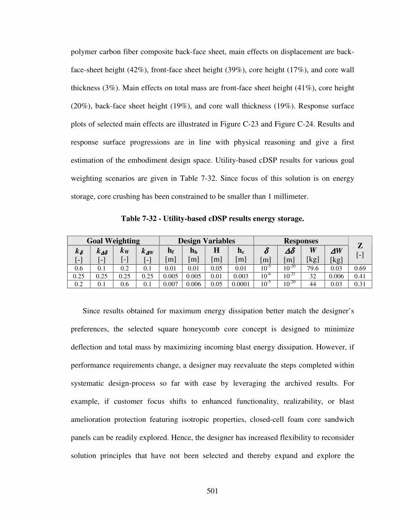
501
polymer carbon fiber composite back-face sheet, main effects on displacement are back-
face-sheet height (42%), front-face sheet height (39%), core height (17%), and core wall
thickness (3%). Main effects on total mass are front-face sheet height (41%), core height
(20%), back-face sheet height (19%), and core wall thickness (19%). Response surface
plots of selected main effects are illustrated in Figure C-23 and Figure C-24. Results and
response surface progressions are in line with physical reasoning and give a first
estimation of the embodiment design space. Utility-based cDSP results for various goal
weighting scenarios are given in Table 7-32. Since focus of this solution is on energy
storage, core crushing has been constrained to be smaller than 1 millimeter.
Table 7-32 - Utility-based cDSP results energy storage.
Goal Weighting Design Variables Responses
kδδδδ
[-] k∆δ∆δ∆δ∆δ
[-]
kW
[-] k∆∆∆∆W
[-]
hf
[m] hb
[m] H
[m] hc
[m] δδδδ
[m] ∆δ∆δ∆δ∆δ [m]
W [kg]
∆∆∆∆W [kg]
Z [-]
0.6 0.1 0.2 0.1 0.01 0.01 0.05 0.01 10-5 10-20 79.6 0.03 0.69
0.25 0.25 0.25 0.25 0.005 0.005 0.01 0.003 10-6 10-21 32 0.006 0.41
0.2 0.1 0.6 0.1 0.007 0.006 0.05 0.0001 10-5 10-20 44 0.03 0.31
Since results obtained for maximum energy dissipation better match the designer’s
preferences, the selected square honeycomb core concept is designed to minimize
deflection and total mass by maximizing incoming blast energy dissipation. However, if
performance requirements change, a designer may reevaluate the steps completed within
systematic design-process so far with ease by leveraging the archived results. For
example, if customer focus shifts to enhanced functionality, realizability, or blast
amelioration protection featuring isotropic properties, closed-cell foam core sandwich
panels can be readily explored. Hence, the designer has increased flexibility to reconsider
solution principles that have not been selected and thereby expand and explore the
502
conceptual design space further or reevaluate selection when performance requirements
change. Especially the sandwich core can serve various mechanisms to fulfill the function
“dissipate energy”, including effects of fill particles, fluids or phase transforming
materials or structures (for example various solid and liquid dampers, strain rate
dependent materials, crushing honeycomb core structures, or nanowire arrays), as
classified in the design catalog presented in Table 4-4. Additionally, the sandwich core
can be modeled as filled with various fluids or particles as well as closed or open cell
foams.
7.5.2 Discussion Concept Exploration and Selection
In the context of the reactive material containment example, various principal
solution alternatives to the specified functional relationships have been derived based on
functional analysis, abstraction and synthesis leveraging design catalogs classifying
phenomena and associated solution principles on multiple scales. Various promising
phenomena and associated solution principles have for example been identified and
evaluated in Table 7-5, Table 7-6, and Table 7-7. However, only the most promising
phenomena and associated solution principles have been considered and mapped in the
concept selection charts shown in Figure 7-21 and Figure 7-22 to avoid “concept
explosion”. Out of those, the most promising solution principles have been selected using
sDSPs implemented in DSIDES, summarized in a morphological matrix shown in Table
7-14, systematically varied, and firmed up into concepts. These concepts then have been
503
explored using partially and fully instantiated cDSPs to select and embody a principal
solution.
In order to verify and validate this function-based systematic approach to the
integrated design of product and material concepts, results of the reactive material
containment system example are evaluated with respect to the concept flexibility
indicators described in detail in Chapter 4:
• Concept quantity:
Exploring the multitude of concepts that can be derived through
systematically varying the solution principles for various functional relationships,
such as the core functions storing energy, listed in Table 7-6, and dissipating
energy, listed in Table 7-7, yields a nearly countless number of concepts. For
example, 19 solution principles have been preliminary selected for realizing the
function “store energy”, and 11 for realizing the function “dissipate energy”.
Hence, systematic variation of solution principles for these two core functions
only leads to 209 different concepts.
The multitude of solution principles for the two core functions of storing and
dissipating energy are associated with one phenomenon, namely (in)elastic
deformation, only. Considering other phenomena as listed in Table 7-5 or more
solution principles to auxiliary functions would quadruple the number of potential
concepts. Thus, as seen by the multitude of promising solution principles mapped
in the concept selection charts shown in Figure 7-21 and Figure 7-22, systematic
function-based analysis, abstraction and synthesis coupled with systematic
variation on system levels including the materials levels leads to significantly
504
increased concept quantity and hence concept flexibility compared to the baseline
designer practicing conceptual product design followed by materials selection.
• Ease of concept generation:
Function-based analysis, abstraction and synthesis and the associated
functional decomposition leads to increased modularity and decreased complexity
by considering functional relationships of the coupled product and material
system at first in isolation, and only then in combination. For example, functional
decoupling during the solution finding process significantly reduces complexity in
systems design because performance requirement changes may not affect the
entire system but only specific functions. This becomes crucial when dealing with
integrated product and materials design on multiple levels and scales. Functional
decomposition not only reduces complexity but also leads to increased system
modularity in systems design, allowing designers to respond quickly to dynamic,
seemingly unquenchable demands.
For example, if customer focus shifts to enhanced functionality, realizability,
or blast amelioration protection featuring isotropic properties, steps completed
within the systematic approach are revaluated. In this specific case, performance
of closed-cell foam core sandwich panels can be readily explored by leveraging
results achieved so far. Also, if blast resistant panels are required not for
containment systems of reactive materials but for example vehicles or personal
armor, solution principles to dissipate energy can readily be revaluated to satisfy
associated changes in performance requirements.
505
At the same time, functional decomposition based on multilevel function
structures, as illustrated in Section 7.3.1, decouples the coupled product and
material system. Thus, through function-based analysis, abstraction and synthesis,
non-intuitive solution principles are easier to identify and evaluate based on the
given performance requirements than when looking at the coupled product and
material system as a whole, as illustrated in Table 7-5, Table 7-6, and Table 7-7.
Functional decomposition may thus facility design for modularity and hence
increase a designer’s product flexibility as well.
Also, making use of design catalogs classifying phenomena and associated
solution principles on the multiscale materials level has made domain expertise
easily accessible and reusable during conceptual design of the reactive material
containment system, as shown in Sections 7.3.2, 7.3.3, 7.3.4, and 7.3.5.
Classifying solution principles to functions leads to archivable and hence reusable
domain expertise. Thus, materials science specific expertise becomes available to
systems designers, bringing materials design further upfront in the design-process
and hence supporting concurrent design. Having ready access to classified and
reusable domain expertise thus increases a designer’s domain-independence in the
early phases of the solution-finding process and supports retrieval – the most
efficient form of solution finding. Also, function-based design permits the
definition of independent subtasks and their allocation to individual disciplines
and domain experts involved in subsequent embodiment design. Thus, it
facilitates integration of domain expertise from a problem-directed and systems
perspective.
506
• Concept variety:
Visualization and systematic variation of functional relationships on various
system levels including the materials level as shown in Figure 7-8, Figure 7-9,
and Figure 7-10, has already lead to a variety of emerging concepts. This variety
is even increased through i) systematic mapping of various phenomena to
functional relationships, and ii) various solution principles to a specific
phenomenon. In this chapter, it has been shown that a designer’s ability to address
more points in the design space compared to focusing on a single concept is
increased by i) mapping performance ranges of only the most promising solution
principles identified through function-based analysis, abstraction and synthesis in
attention directing concept selection charts, as illustrated in Figure 7-21 and
Figure 7-22, or ii) exploring a variety of different concepts as shown in Section
7.4. In other words, it has been shown that through function-based systematic
integrated design of product and materials concepts, designers are enabled to
access significantly more points in the design space and hence achieve increased
system performance compared to the baseline designer practicing conceptual
product design followed by materials selection. Hence, a designer’s concept
flexibility is increased through function-based integrated design of product and
material concepts in a systematic fashion.
• Concept novelty:
As shown for example in Table 7-5, systematic function-based design
leveraging design catalogs on multiple levels and scales supports retrieval of
solution principles from multiple disciplines. Combination and systematic
507
variation of already classified phenomena and solution principles for various
functions may facilitate the design of novel concepts. Even though solution
principles to individual functions may be known, their combination and
systematic variation from a systems perspective may lead to non-intuitive system
concepts, such as reactive metal powder mixtures in combination with
multifunctional blast resistant panels. For example, the use of electrodynamic
effects to change incoming blast energy by for example decelerating a conducting
front-face sheet of the containment system in an electromagnetic field has not yet
been envisioned for blast protection. Also, combining plate bending and
deformation of nanowire arrays or materials undergoing martensitic
transformations, as shown in Table 7-6 has not yet been leveraged for blast
protection. Hence, synthesizing solution principles to various functions in new
ways within a function-based systematic approach yields the design of novel
concepts.
In order to avoid obtaining an unmanageable large amount of alternatives
through systematic variation, infeasible combinations of solution principles must
be eliminated. Even if a novel concept does not evolve from combinations of
solution principles for certain functions, these combinations provide a starting
point for further exploration and investigation of novel solution principles. Thus,
systematic design principles not only support retrieval and combination of known
solution principles into principal solution alternatives but also facilitate the search
for novel solution principles and thus encourage the design of novel concepts in
the early phases of design.
508
At the same time, systematic function-based design leveraging design
catalogs on multiple levels and scales facilitates managing a variety of potentially
novel concepts. By focusing on phenomena and associated solution principles but
not a specific case or material artifact, a designer is able to step out of the
technological cycle of obsolescence and evolution. Operating at the level of
phenomena and associated solution principles, a particular material/system at any
given time is only illustrative of the possibilities, not their determinant. Concepts
can hence be linked to governing solution principles and phenomena, classified in
design catalogs in this work. These design catalogs thus facilitate management of
concepts and evaluation of their novelty.
• Concept realizability:
Realizability, i.e., manufacturing complexity and flexibility as well as
resistance against temperature, chemical or other environmental effects is
considered through template-based systematic decision support based on sDSPs.
Within the sDSP formulations, these criteria are considered in addition to
performance criteria through attribute ratings. These ratings and associated
viewpoints have been described in Section 7.3.6 and detailed in Appendix A-2,
based on the performance requirements given in Table 1-6.
Since relative importance and ratings of selection attributes are not known
very accurately, a post-solution sensitivity analysis is performed using exact
interval arithmetic to manage this uncertainty. As a result of this analysis, the best
possible and worst possible rank for an alternative (taking this uncertainty into
consideration) is obtained. However, it is emphasized that selection results are
509
obtained under uncertainty caused by the lack of detailed design information in
the conceptual and early embodiment stages. Hence, selection results are to be
critically evaluated. Also, different concepts are to be explored before selection is
narrowed down to a principal solution. Therefore, selection results obtained in
this work have been critically evaluated and validated through concept
exploration, as described in Section 7.4.
Besides increases in concept quantity, variety, novelty and ease of concept
generation, using a systematic, problem directed approach to integrated product and
materials design leads to increased transparency, design-process modularity and
reconfigurability, as well as comprehensive design space expansion and exploration. Of
course, a more “active engagement” of designers is required as for example in conceptual
product design followed by materials selection. Also, comprehensive design space
expansion and exploration is based on design catalogs, which are “living documents”,
and might lead to “concept explosion” if promising concepts are not eliminated early
enough. Nevertheless, the main advantage of expanding and comprehensively exploring
the design space during the conceptual design phase leads to “informed decisions”, i.e., a
designer has explored the conceptual design space before making decisions and
allocating resources for the rest of a product’s life cycle. The key advantage to this
function-based systematic approach to the integrated design of product and materials
concepts is to enable a designer to operate at the level of fundamental phenomena and
associated solution principles; in other words a particular material system at any given
time is only illustrative of the possibilities, not their determinant.
510
7.6 Steps 3 and 4 – Design-Process Generation and Selection
Having generated and evaluated a variety of concepts in the context of the reactive
material containment example through functional analysis, abstraction and synthesis
leveraging design catalogs classifying phenomena and associated solution principles on
multiple scales, the most promising solution principles have been selected using sDSPs
implemented in DSIDES, systematically varied, and firmed up into concepts. These
concepts then have been explored using partially and fully instantiated cDSPs to select a
principal solution.
In this section, the focus is on systematic generation and selection of design-process
alternatives based on principles from information economics in the context of designing
multifunctional blast resistant panels constituting the containment system to protect the
enclosed reactive material only. This involves Steps 3 and 4 of the systematic approach
presented in Figure 7-37. Various design-process alternatives are instantiated by
replacing analysis blocks in the template-based cDSP formulation, as illustrated in Figure
7-37.
The goal is to find a satisficing design-process alternative in the context of the
reactive material containment system example clarified in 8.2. These design-process
alternatives and the additional modeling potential are then evaluated through a value-of-
information-based Process Performance Indicator from a decision-centric view of design,
i.e., based on the fundamental assumption that analysis models are used to make better
decisions. Hence, design-process generation is driven by the need to improve decision
making capability through a value-of-information-based design-process design strategy,
as illustrated in Figure 7-38.
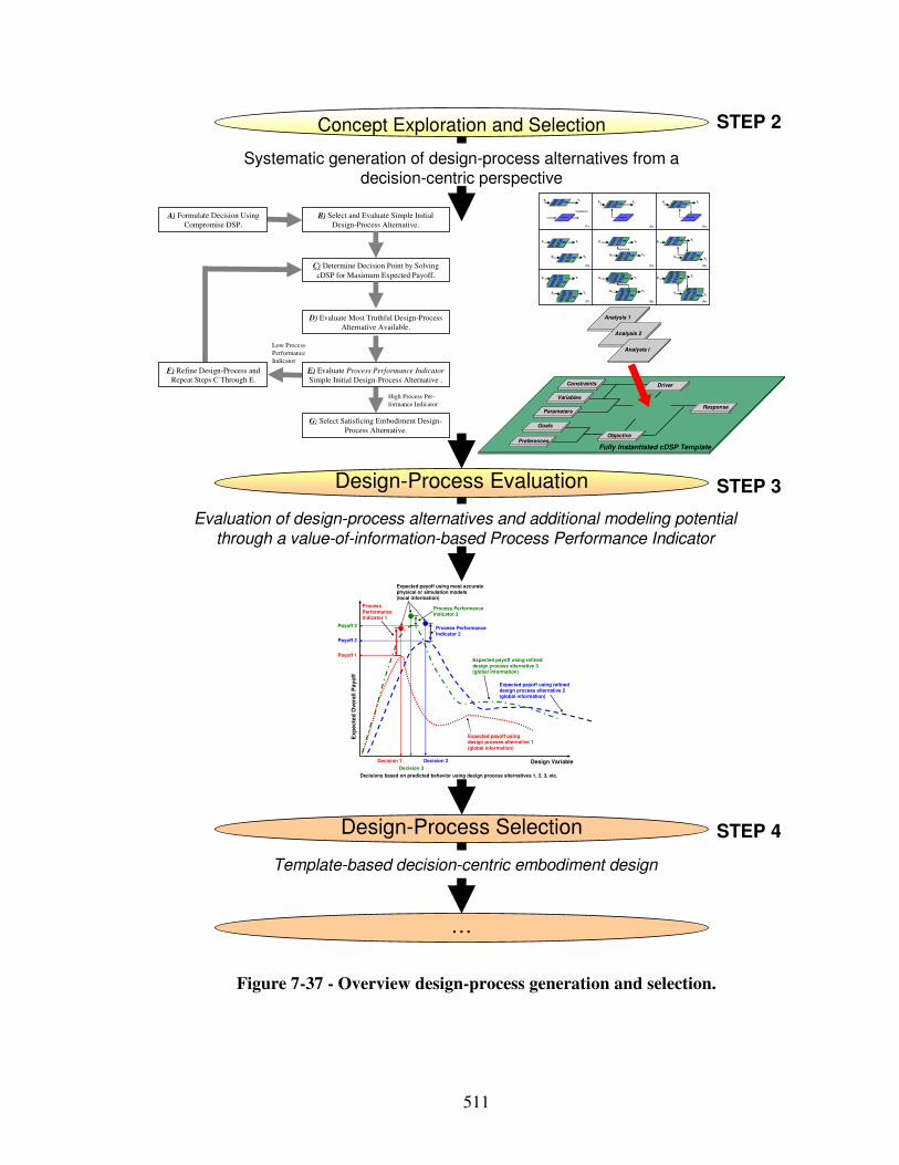
511
Evaluation of design-process alternatives and additional modeling potential through a value-of-information-based Process Performance Indicator
Systematic generation of design-process alternatives from a decision-centric perspective
Design-Process Evaluation
Design-Process Selection
Concept Exploration and Selection
Template-based decision-centric embodiment design
Design Variable
Ex
pe
cte
d O
ve
rall
Pa
yo
ff
Expected payoff usingdesign process alternative 1(global information)
Expected payoff using refined design process alternative 2(global information)
Payoff 2
Decision 1 Decision 2
Payoff 1
Process Performance Indicator 1
Expected payoff using most accurate physical or simulation models(local information)
Process Performance Indicator 2
Decisions based on predicted behavior using design process alternatives 1, 2, 3, etc.
Process Performance Indicator 3
Expected payoff using refined design process alternative 3(global information)
Payoff 3
Decision 3
…
Go als
P referenc es
Vari abl es
Pa ra meters
Con strain ts
Re spo nse
Obj ect i ve
Fully Instantia ted cDSPTemplate
D ri ver
A nal ysi s
Go als
P referenc es
Vari abl es
Pa ra meters
Con strain ts
Re spo nse
Obj ect i ve
Fully Instantia ted cDSPTemplate
D ri ver
A nal ysi s
P1 P2 P3
P6
P9P8P7
P4 P5
Validation
X1 Y1
X2 Y2
X1 Y1
X2 Y2
X1
Y1
X2 Y2
Analysis i
Go als
P referenc es
Vari abl es
Pa ra meters
Con strain ts
Re spo nse
Obj ect i ve
F ul l y In s tan t i a ted c D S P T e mp l a te
D ri ver
A nal ysi s
Go als
P referenc es
Vari abl es
Pa ra meters
Con strain ts
Re spo nse
Obj ect i ve
F ul l y In s tan t i a ted c D S P T e mp l a te
D ri ver
A nal ysi s
Analysis i
Go als
P referenc es
Vari abl es
Pa ra meters
Con strain ts
Re spo nse
Obj ect i ve
F ul l y In s tan t i a ted c D S P T e mp l a te
D ri ver
A nal ysi s
Analysis i
Go al s
Preferen ces
Va ri ab le s
P arameters
Co nstrai nts
Res pon se
Ob je ct ive
Fully Instantiated cDSP Template
Dri ver
An aly si s
X1 Y1 X1 Y1 X1 Y1
Go als
P referenc es
Vari abl es
Pa ra meters
Con strain ts
Re spo nse
Obj ect i ve
Fully Instantia ted cDSPTemplate
D ri ver
A nal ysi s Go als
P referenc es
Vari abl es
Pa ra meters
Con strain ts
Re spo nse
Obj ect i ve
Fully Instantia ted cDSPTemplate
D ri ver
A nal ysi s
Go als
P referenc es
Vari abl es
Pa ra meters
Con strain ts
Re spo nse
Obj ect i ve
Fully Instantia ted cDSPTemplate
D ri ver
A nal ysi s
Go als
P referenc es
Vari abl es
Pa ra meters
Con strain ts
Re spo nse
Obj ect i ve
Fully Instantia ted cDSPTemplate
D ri ver
A nal ysi s
Go als
P referenc es
Vari abl es
Pa ra meters
Con strain ts
Re spo nse
Obj ect i ve
Fully Instantia ted cDSPTemplate
D ri ver
A nal ysi s
X1 Y1
X2 Y2
X1 Y1
X2 Y2
X1
Y1
X2 Y2
Go al s
Preferen ces
Va ri ab le s
P arameters
Co nstrai nts
Res pon se
Ob je ct ive
Fully Instantiated cDSP Template
Dri ver
An aly si s
Go als
P referenc es
Vari abl es
Pa ra meters
Con strain ts
Re spo nse
Obj ect i ve
Fully Instantia ted cDSPTemplate
D ri ver
A nal ysi s Go als
P referenc es
Vari abl es
Pa ra meters
Con strain ts
Re spo nse
Obj ect i ve
Fully Instantia ted cDSPTemplate
D ri ver
A nal ysi s
Go als
P referenc es
Vari abl es
Pa ra meters
Con strain ts
Re spo nse
Obj ect i ve
Fully Instantia ted cDSPTemplate
D ri ver
A nal ysi s
Go als
P referenc es
Vari abl es
Pa ra meters
Con strain ts
Re spo nse
Obj ect i ve
Fully Instantia ted cDSPTemplate
D ri ver
A nal ysi s
Go als
P referenc es
Vari abl es
Pa ra meters
Con strain ts
Re spo nse
Obj ect i ve
Fully Instantia ted cDSPTemplate
D ri ver
A nal ysi s
Go al s
Preferen ces
Va ri ab le s
P arameters
Co nstrai nts
Res pon se
Ob je ct ive
Fully Instantiated cDSP Template
Dri ver
An aly si s
Go al s
Preferen ces
Va ri ab le s
P arameters
Co nstrai nts
Res pon se
Ob je ct ive
Fully Instantiated cDSP Template
Dri ver
An aly si s
Go als
P referenc es
Vari abl es
Pa ra meters
Con strain ts
Re spo nse
Obj ect i ve
Fully Instantia ted cDSPTemplate
D ri ver
A nal ysi s
Go als
P referenc es
Vari abl es
Pa ra meters
Con strain ts
Re spo nse
Obj ect i ve
Fully Instantia ted cDSPTemplate
D ri ver
A nal ysi s
Go als
P referenc es
Vari abl es
Pa ra meters
Con strain ts
Re spo nse
Obj ect i ve
Fully Instantia ted cDSPTemplate
D ri ver
A nal ysi s
Go als
P referenc es
Vari abl es
Pa ra meters
Con strain ts
Re spo nse
Obj ect i ve
Fully Instantia ted cDSPTemplate
D ri ver
A nal ysi s
Go als
P referenc es
Vari abl es
Pa ra meters
Con strain ts
Re spo nse
Obj ect i ve
Fully Instantia ted cDSPTemplate
D ri ver
A nal ysi s Go als
P referenc es
Vari abl es
Pa ra meters
Con strain ts
Re spo nse
Obj ect i ve
Fully Instantia ted cDSPTemplate
D ri ver
A nal ysi s
Go als
P referenc es
Vari abl es
Pa ra meters
Con strain ts
Re spo nse
Obj ect i ve
Fully Instantia ted cDSPTemplate
D ri ver
A nal ysi s
Go als
P referenc es
Vari abl es
Pa ra meters
Con strain ts
Re spo nse
Obj ect i ve
Fully Instantia ted cDSPTemplate
D ri ver
A nal ysi s
STEP 3
STEP 2
STEP 4
B) Select and Evaluate Simple Initial
Design-Process Alternative.
D) Evaluate Most Truthful Design-Process
Alternative Available.
G: Select Satisficing Embodiment Design-
Process Alternative.
A) Formulate Decision Using
Compromise DSP.
C) Determine Decision Point by Solving
cDSP for Maximum Expected Payoff.
High Process Per-
formance Indicator
Low Process
Performance
Indicator
E) Evaluate Process Performance Indicator
Simple Initial Design-Process Alternative .
F) Refine Design-Process and
Repeat Steps C Through E.
Goals
Preferences
Variables
Parameters
Constraints
Response
Objective
Analysis 1
Fully Instantiated cDSP Template
Driver
Analysis 2
Analysis i
Figure 7-37 - Overview design-process generation and selection.
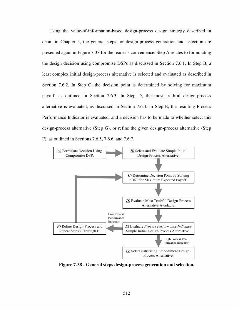
512
Using the value-of-information-based design-process design strategy described in
detail in Chapter 5, the general steps for design-process generation and selection are
presented again in Figure 7-38 for the reader’s convenience. Step A relates to formulating
the design decision using compromise DSPs as discussed in Section 7.6.1. In Step B, a
least complex initial design-process alternative is selected and evaluated as described in
Section 7.6.2. In Step C, the decision point is determined by solving for maximum
payoff, as outlined in Section 7.6.3. In Step D, the most truthful design-process
alternative is evaluated, as discussed in Section 7.6.4. In Step E, the resulting Process
Performance Indicator is evaluated, and a decision has to be made to whether select this
design-process alternative (Step G), or refine the given design-process alternative (Step
F), as outlined in Sections 7.6.5, 7.6.6, and 7.6.7.
B) Select and Evaluate Simple Initial
Design-Process Alternative.
D) Evaluate Most Truthful Design-Process
Alternative Available.
G: Select Satisficing Embodiment Design-
Process Alternative.
A) Formulate Decision Using
Compromise DSP.
C) Determine Decision Point by Solving
cDSP for Maximum Expected Payoff.
High Process Per-
formance Indicator
Low Process
Performance
Indicator
E) Evaluate Process Performance Indicator
Simple Initial Design-Process Alternative .
F) Refine Design-Process and
Repeat Steps C Through E.
Figure 7-38 - General steps design-process generation and selection.
513
7.6.1 Step A: Formulate Decisions Using Compromise DSP
In general, the first step is to formulate the design decision. The decision formulation
used is the utility-based cDSP formulation given in Table 7-21, consisting of information
about design variables, responses, simulation models used for evaluating responses from
design variables, a designer’s preferences, constraints, and goals. Here, focus is on safety,
i.e., minimum deflection first, and minimum weight second. Goals are weighted
accordingly.
It is important to note that changing the utility function will have effect on the
specific decisions (values of design variables and Process Performance Indicators) made
using the method. However, it does not affect the steps followed in the method. Even by
changing the preferences, the conclusions about the applicability of the method and the
metrics derived from the method remain the same.
7.6.2 Step B: Select Least Complex Initial Design-Process Alternative
A design-process based on an analytical analysis model is used as the least complex
initial design-process alternative to predict performance, i.e., deflection and mass per
area, of square honeycomb core sandwich structures. The analysis model used is based on
the work of Fleck and Deshpande [210], Hutchinson and Xue [286], as well as Muchnik
and coauthors [438].
The work of Hutchinson and Xue is based on a proper treatment of underlying
physical mechanisms. Also, it matches very well with experiments and extensive finite
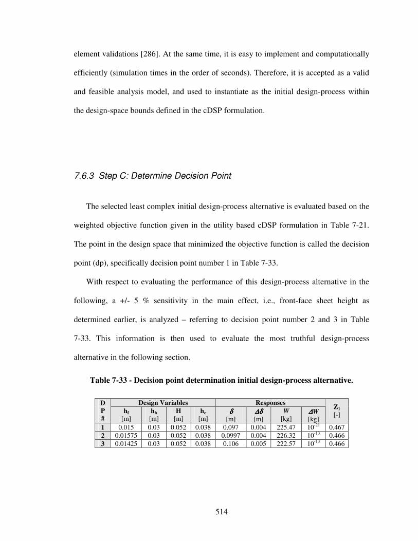
514
element validations [286]. At the same time, it is easy to implement and computationally
efficiently (simulation times in the order of seconds). Therefore, it is accepted as a valid
and feasible analysis model, and used to instantiate as the initial design-process within
the design-space bounds defined in the cDSP formulation.
7.6.3 Step C: Determine Decision Point
The selected least complex initial design-process alternative is evaluated based on the
weighted objective function given in the utility based cDSP formulation in Table 7-21.
The point in the design space that minimized the objective function is called the decision
point (dp), specifically decision point number 1 in Table 7-33.
With respect to evaluating the performance of this design-process alternative in the
following, a +/- 5 % sensitivity in the main effect, i.e., front-face sheet height as
determined earlier, is analyzed – referring to decision point number 2 and 3 in Table
7-33. This information is then used to evaluate the most truthful design-process
alternative in the following section.
Table 7-33 - Decision point determination initial design-process alternative.
Design Variables Responses D
P
#
hf [m]
hb
[m] H
[m] hc
[m] δδδδ
[m] ∆δ∆δ∆δ∆δ [m]
W
[kg] ∆∆∆∆W [kg]
Z1
[-]
1 0.015 0.03 0.052 0.038 0.097 0.004 225.47 10-21 0.467
2 0.01575 0.03 0.052 0.038 0.0997 0.004 226.32 10-13 0.466
3 0.01425 0.03 0.052 0.038 0.106 0.005 222.57 10-13 0.466
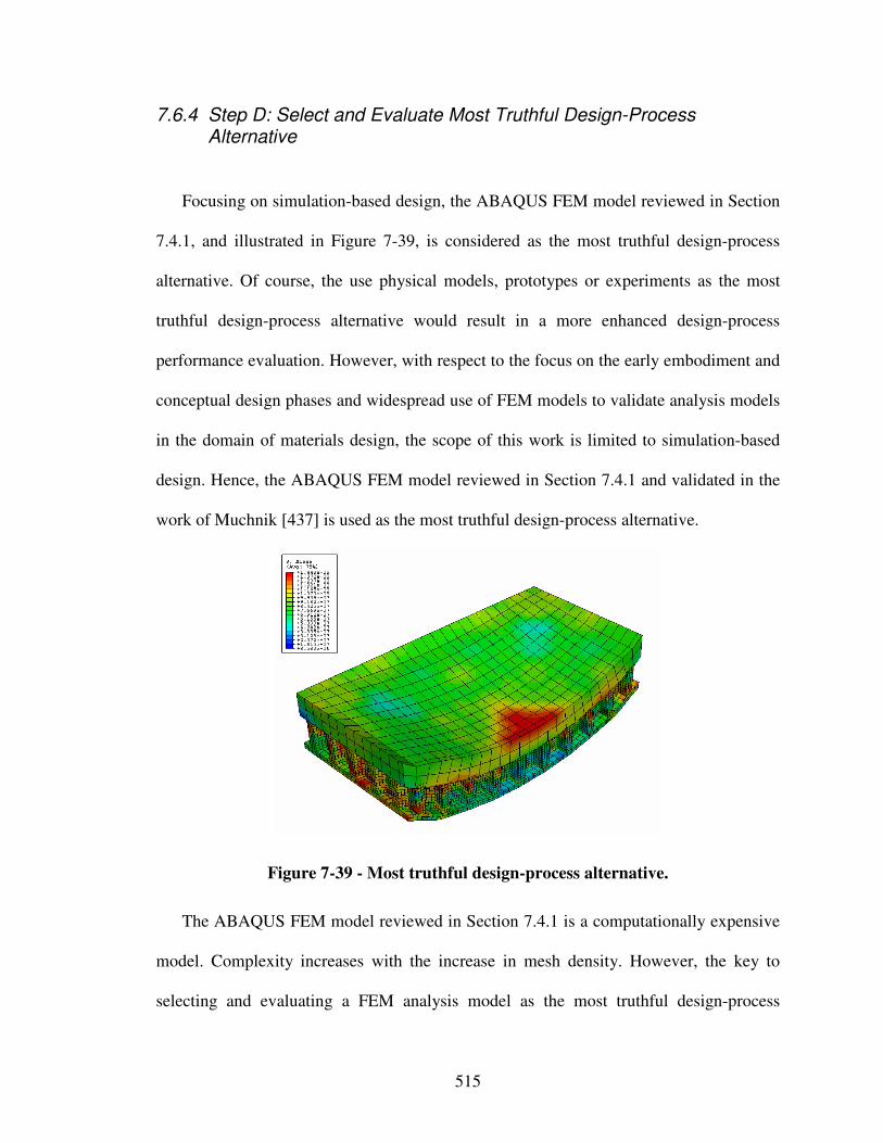
515
7.6.4 Step D: Select and Evaluate Most Truthful Design-Process Alternative
Focusing on simulation-based design, the ABAQUS FEM model reviewed in Section
7.4.1, and illustrated in Figure 7-39, is considered as the most truthful design-process
alternative. Of course, the use physical models, prototypes or experiments as the most
truthful design-process alternative would result in a more enhanced design-process
performance evaluation. However, with respect to the focus on the early embodiment and
conceptual design phases and widespread use of FEM models to validate analysis models
in the domain of materials design, the scope of this work is limited to simulation-based
design. Hence, the ABAQUS FEM model reviewed in Section 7.4.1 and validated in the
work of Muchnik [437] is used as the most truthful design-process alternative.
Figure 7-39 - Most truthful design-process alternative.
The ABAQUS FEM model reviewed in Section 7.4.1 is a computationally expensive
model. Complexity increases with the increase in mesh density. However, the key to
selecting and evaluating a FEM analysis model as the most truthful design-process
516
alternative is to determine the mesh size at which discretization errors converge to zero.
In this work, Richardson extrapolation [543] is used as the strategy to evaluate
discretization errors, i.e., errors that consist of the difference between the exact solution
of the governing equations and the corresponding solution of the algebraic system.
Discretization errors are primarily associated with both the mesh (structured,
unstructured, uniform, etc.) and the discretization method (Finite Elements, Finite
Volumes, Boundary Elements, Spectral methods, etc.) [694]. Assuming that the exact
solution is smooth enough that the Taylor series expansion for the error is justified, the
formal convergence (error) is of second order, and the mesh spacing is sufficiently small
such that the leading-order error term dominates the total discretization error (i.e., the
convergence is monotonic in the asymptotic range), the discretization error, εh, is
estimated using two different nested meshes, hi and hj (assuming that the refinement
ration r = hi/hj > 1), as illustrated in Equation 12:
12 −
−≅−=
r
i
i
hhj
hexact
φφφφε Equation 12
where φexact is the “exact” solution of the governing equations at a given point x, φ h is the
discrete solution. Using the Richardson extrapolation error estimation in the context of
the ABAQUS FEM analysis model reviewed in Section 7.4.1, a mesh size of 0.005 is
determined as the mesh size at which discretization errors converge to zero.
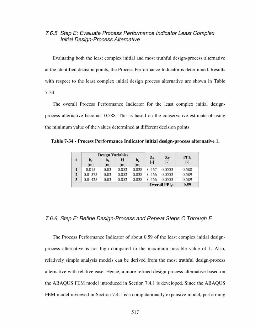
517
7.6.5 Step E: Evaluate Process Performance Indicator Least Complex Initial Design-Process Alternative
Evaluating both the least complex initial and most truthful design-process alternative
at the identified decision points, the Process Performance Indicator is determined. Results
with respect to the least complex initial design process alternative are shown in Table
7-34.
The overall Process Performance Indicator for the least complex initial design-
process alternative becomes 0.588. This is based on the conservative estimate of using
the minimum value of the values determined at different decision points.
Table 7-34 - Process Performance Indicator initial design-process alternative 1.
Design Variables # hf
[m] hb
[m] H
[m] hc
[m]
Z1 [-]
ZT
[-] PPI1
[-]
1 0.015 0.03 0.052 0.038 0.467 0.0553 0.588
2 0.01575 0.03 0.052 0.038 0.466 0.0553 0.589
3 0.01425 0.03 0.052 0.038 0.466 0.0553 0.589
Overall PPI1: 0.59
7.6.6 Step F: Refine Design-Process and Repeat Steps C Through E
The Process Performance Indicator of about 0.59 of the least complex initial design-
process alternative is not high compared to the maximum possible value of 1. Also,
relatively simple analysis models can be derived from the most truthful design-process
alternative with relative ease. Hence, a more refined design-process alternative based on
the ABAQUS FEM model introduced in Section 7.4.1 is developed. Since the ABAQUS
FEM model reviewed in Section 7.4.1 is a computationally expensive model, performing
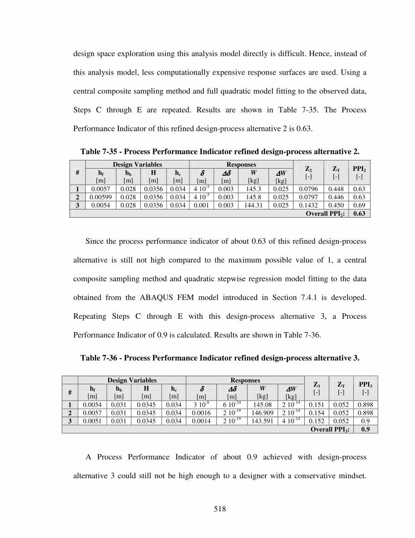
518
design space exploration using this analysis model directly is difficult. Hence, instead of
this analysis model, less computationally expensive response surfaces are used. Using a
central composite sampling method and full quadratic model fitting to the observed data,
Steps C through E are repeated. Results are shown in Table 7-35. The Process
Performance Indicator of this refined design-process alternative 2 is 0.63.
Table 7-35 - Process Performance Indicator refined design-process alternative 2.
Design Variables Responses
# hf [m]
hb
[m] H
[m] hc
[m] δδδδ
[m] ∆δ∆δ∆δ∆δ [m]
W
[kg] ∆∆∆∆W [kg]
Z2 [-]
ZT
[-] PPI2
[-]
1 0.0057 0.028 0.0356 0.034 4 10-5 0.003 145.3 0.025 0.0796 0.448 0.63
2 0.00599 0.028 0.0356 0.034 4 10-5 0.003 145.8 0.025 0.0797 0.446 0.63
3 0.0054 0.028 0.0356 0.034 0.001 0.003 144.31 0.025 0.1432 0.450 0.69
Overall PPI2: 0.63
Since the process performance indicator of about 0.63 of this refined design-process
alternative is still not high compared to the maximum possible value of 1, a central
composite sampling method and quadratic stepwise regression model fitting to the data
obtained from the ABAQUS FEM model introduced in Section 7.4.1 is developed.
Repeating Steps C through E with this design-process alternative 3, a Process
Performance Indicator of 0.9 is calculated. Results are shown in Table 7-36.
Table 7-36 - Process Performance Indicator refined design-process alternative 3.
Design Variables Responses
# hf
[m] hb
[m] H
[m] hc
[m] δδδδ
[m] ∆δ∆δ∆δ∆δ [m]
W
[kg] ∆∆∆∆W [kg]
Z3 [-]
ZT
[-] PPI3
[-]
1 0.0054 0.031 0.0345 0.034 3 10-8 6 10-24 145.08 2 10-14 0.151 0.052 0.898
2 0.0057 0.031 0.0345 0.034 0.0016 2 10-19 146.909 2 10-14 0.154 0.052 0.898
3 0.0051 0.031 0.0345 0.034 0.0014 2 10-19 143.591 4 10-14 0.152 0.052 0.9
Overall PPI3: 0.9
A Process Performance Indicator of about 0.9 achieved with design-process
alternative 3 could still not be high enough to a designer with a conservative mindset.
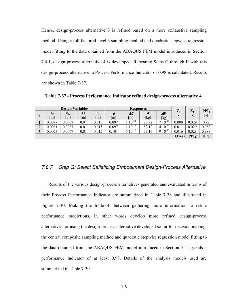
519
Hence, design-process alternative 3 is refined based on a more exhaustive sampling
method. Using a full factorial level 3 sampling method and quadratic stepwise regression
model fitting to the data obtained from the ABAQUS FEM model introduced in Section
7.4.1, design-process alternative 4 is developed. Repeating Steps C through E with this
design-process alternative, a Process Performance Indicator of 0.98 is calculated. Results
are shown in Table 7-37.
Table 7-37 - Process Performance Indicator refined design-process alternative 4.
Design Variables Responses
# hf
[m] hb
[m] H
[m] hc
[m] δδδδ
[m] ∆δ∆δ∆δ∆δ [m]
W
[kg] ∆∆∆∆W [kg]
Z4 [-]
ZT
[-] PPI4
[-]
1 0.0077 0.0067 0.01 0.015 0.097 1 10-24 80.82 7 10-15 0.009 0.029 0.98
2 0.0081 0.0067 0.01 0.015 0.097 1 10-24 82.12 4 10-15 0.011 0.029 0.982
3 0.0073 0.0067 0.01 0.015 0.101 5 10-17 79.16 9 10-15 0.016 0.028 0.988
Overall PPI4: 0.98
7.6.7 Step G: Select Satisficing Embodiment Design-Process Alternative
Results of the various design-process alternatives generated and evaluated in terms of
their Process Performance Indicator are summarized in Table 7-38 and illustrated in
Figure 7-40. Making the trade-off between gathering more information to refine
performance predictions, in other words develop more refined design-process
alternatives, or using the design-process alternative developed so far for decision making,
the central composite sampling method and quadratic stepwise regression model fitting to
the data obtained from the ABAQUS FEM model introduced in Section 7.4.1 yields a
performance indicator of at least 0.98. Details of the analysis models used are
summarized in Table 7-39.
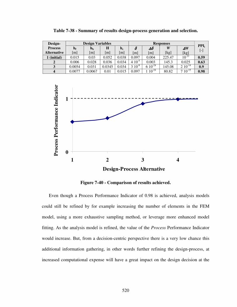
520
Table 7-38 - Summary of results design-process generation and selection.
Design Variables Responses Design-
Process
Alternative
hf
[m] hb
[m] H
[m] hc
[m] δδδδ
[m] ∆δ∆δ∆δ∆δ [m]
W
[kg] ∆∆∆∆W [kg]
PPIi
[-]
1 (initial) 0.015 0.03 0.052 0.038 0.097 0.004 225.47 10-21 0.59
2 0.006 0.028 0.036 0.034 4 10-5 0.003 145.3 0.025 0.63
3 0.0054 0.031 0.0345 0.034 3 10-8 6 10-24 145.08 2 10-14 0.9
4 0.0077 0.0067 0.01 0.015 0.097 1 10-24 80.82 7 10-15 0.98
0
1
1 2 3 4
Design-Process Alternative
Pro
cess
Per
form
an
ce I
nd
ica
tor
Figure 7-40 - Comparison of results achieved.
Even though a Process Performance Indicator of 0.98 is achieved, analysis models
could still be refined by for example increasing the number of elements in the FEM
model, using a more exhaustive sampling method, or leverage more enhanced model
fitting. As the analysis model is refined, the value of the Process Performance Indicator
would increase. But, from a decision-centric perspective there is a very low chance this
additional information gathering, in other words further refining the design-process, at
increased computational expense will have a great impact on the design decision at the
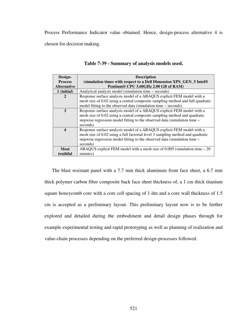
521
Process Performance Indicator value obtained. Hence, design-process alternative 4 is
chosen for decision making.
Table 7-39 - Summary of analysis models used.
Design-
Process
Alternative
Description
(simulation times with respect to a Dell Dimension XPS_GEN_5 Intel®
Pentium® CPU 3.60GHz 2.00 GB of RAM)
1 (initial) Analytical analysis model (simulation time ~ seconds)
2 Response surface analysis model of a ABAQUS explicit FEM model with a mesh size of 0.02 using a central composite sampling method and full quadratic model fitting to the observed data (simulation time ~ seconds)
3 Response surface analysis model of a ABAQUS explicit FEM model with a mesh size of 0.02 using a central composite sampling method and quadratic stepwise regression model fitting to the observed data (simulation time ~ seconds)
4 Response surface analysis model of a ABAQUS explicit FEM model with a mesh size of 0.02 using a full factorial level 3 sampling method and quadratic stepwise regression model fitting to the observed data (simulation time ~ seconds)
Most
truthful
ABAQUS explicit FEM model with a mesh size of 0.005 (simulation time ~ 20 minutes)
The blast resistant panel with a 7.7 mm thick aluminum front face sheet, a 6.7 mm
thick polymer carbon fiber composite back face sheet thickness of, a 1 cm thick titanium
square honeycomb core with a core cell spacing of 1 dm and a core wall thickness of 1.5
cm is accepted as a preliminary layout. This preliminary layout now is to be further
explored and detailed during the embodiment and detail design phases through for
example experimental testing and rapid prototyping as well as planning of realization and
value-chain processes depending on the preferred design-processes followed.
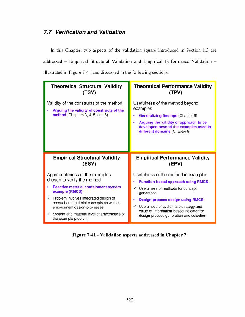
522
7.7 Verification and Validation
In this Chapter, two aspects of the validation square introduced in Section 1.3 are
addressed – Empirical Structural Validation and Empirical Performance Validation –
illustrated in Figure 7-41 and discussed in the following sections.
Empirical Structural Validity (ESV)
Appropriateness of the exampleschosen to verify the method
• Reactive material containment system example (RMCS)
� Problem involves integrated design of product and material concepts as well as embodiment design-processes
� System and material level characteristics of the example problem
Theoretical Performance Validity (TPV)
Usefulness of the method beyond
examples
• Generalizing findings (Chapter 9)
• Arguing the validity of approach to be developed beyond the examples used in different domains (Chapter 9)
Theoretical Structural Validity (TSV)
Validity of the constructs of the method
• Arguing the validity of constructs of the method (Chapters 3, 4, 5, and 6)
Empirical Performance Validity (EPV)
Usefulness of the method in examples
• Function-based approach using RMCS
� Usefulness of methods for concept generation
• Design-process design using RMCS
� Usefulness of systematic strategy and value-of-information-based indicator for design-process generation and selection
Figure 7-41 - Validation aspects addressed in Chapter 7.
523
7.7.1 Empirical Structural Validation
Empirical structural validation involves accepting the appropriateness of the example
problems used to verify the performance of the method. It is believed that reactive
material containment system example is a reasonably complex multilevel and multiscale
design problem. Also, the design problem discussed in this chapter allows significant
increase in system performance by exercising systematic conceptual design not only on
various system levels down to the component level, but, also on the multiscale materials
level, as discussed in Section 7.5. Moreover, the problem is suitable because many
aspects of integrated product and materials design can be demonstrated. Furthermore, the
embodiment design-process can be represented in terms of decisions that can be
mathematically formulated and supported using analysis models. Also, only validated
analysis models of different complexity have been utilized to generate and evaluate
design-process alternatives. Hence, the reactive material containment system example
consists of decisions related to three aspects: product, materials, and design-process
design. All three decisions depend on each other and ultimately affect the final system
performance.
Also, the most truthful design-process alternative for multifunctional blast resistant
panels in the context of the reactive material containment system is characterized by
significant computational time, making it’s use for design-space exploration unfeasible.
This motivates the need for selecting a satisficing design-process alternative such that
there is a balance between impact on decision as well as computational and additional
modeling expense. Hence, the design of multifunctional blast resistant panels in the
context of the reactive material containment system using analytical and FEM analysis
524
models described in Sections 7.4.1 is appropriate for the validation of the value-of-
information-based strategy for design-process generation and selection and the associated
Process Performance Indicator.
7.7.2 Empirical Performance Validation
Empirical performance validation consists of accepting the usefulness of the outcome
with respect to the initial purpose and accepting that the achieved usefulness is related to
applying the method. The empirical performance validation in this chapter is carried out
in two phases – the validation of systematic, function-based, integrated design of material
and product concepts in Sections 7.3 through 7.5 and the value-of-information-based
strategy to design-process generation and selection in Section 7.6.
In Sections 7.3 through 7.5 the creation of multilevel function structures as well as
subsequent function-based analysis, abstraction, synthesis, and systematic variation
leveraging design catalogs for phenomena and associated solution principles has shown a
significant increase in a designer’s concept flexibility by exercising systematic
conceptual design not only on various system levels down to the component level, but,
also on the multiscale materials level, as argued in Section 7.5. Also, identifying solution
principles on the multiscale materials level through function-based analysis, abstraction
and synthesis, systematically combining those into concepts and further exploring and
refining the most promising concepts has shown to increase system performance.
However, the lack of concrete information at these early stages of design is
525
acknowledged. Hence, not one, but multiple most promising concepts are further
explored through template-based instantiations of compromise Decision Support
Problems (cDSPs, before selection is narrowed down to a single concept. For example,
partially instantiated template-based cDSP formulations (where only the constraints,
variables, parameters, goals, response and analysis entities are instantiated) are used to
explore response surfaces throughout the feasible design space as well as identify
extreme values and main effects. Fully instantiated utility-based cDSP formulations
(where driver and objective entities are instantiated additionally) are then used for multi-
objective solution finding to select a most promising principal solution from the set of
feasible concepts identified earlier.
Furthermore, the value-of-information-based strategy for design-process generation
and selection as well as the associated Process Performance Indicator has shown to be
effective for increasing efficiency of design decision making without affecting the quality
of decisions, as shown in Section 7.6. Based on the results from this example, it is
observed that the selected design-process alternative may result in similar decisions as the
most truthful design-process alternative. In other words, the selected design-process may
result in satisficing decisions. Since a stepwise refinement of the design-processes is
carried out, the most truthful design-process alternatives does not need to be executed. A
designer may get the same quality of decisions efficiently through stepwise refinement.
Therefore, it is shown that the Process Performance Indicator is valuable for determining
a satisficing design-process alternative while capturing the effect of both uncertainty in
analysis models and a designer’s preferences from a decision-centric perspective. The
results by using the value of information are acceptable and inline with the designer’s
526
expectations. Hence, it is asserted that empirical performance validity is achieved.
However, a more exhaustive example to validate the value-of-information-based strategy
for design-process generation and selection as well as the associated Process Performance
Indicator is presented in Chapter 8 in the context of the optoelectronic communication
system introduced in Section 1.1.
7.8 Role of Chapter 7 in this Dissertation
In this chapter, an integrated product, materials and design-process example – the
reactive material containment system – is presented for validation of design methods,
attention-directing tools, and metrics developed in Chapters 4, 5, and 6. The relationship
of the validation example presented in this chapter with other dissertation chapters is
presented in Figure 3-11. Results from the integrated product, materials, and design-
process design problem presented in this chapter indicate the usefulness of the proposed
systematic approach.
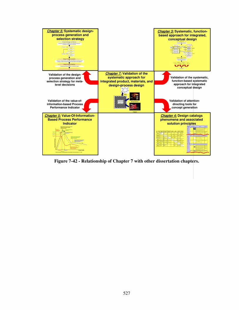
527
Chapter 5: Systematic design-process generation and
selection strategy
Chapter 5: Systematic design-process generation and
selection strategy
Chapter 5: Value-Of-Information-Based Process Performance
Indicator
Chapter 7: Validation of the systematic approach for
integrated product, materials, and design-process design
Chapter 4: Design catalogs phenomena and associated
solution principles
Chapter 3: Systematic, function-based approach for integrated,
conceptual design
Systematic mapping of classified phenomena and solution principles from multiple scales and disciplines to multilevel function structures
Creating multilevel function structures based on functional analysis, abstraction and synthesis
Ex,in
Mx,in
Ex,in
System boundary
System function x Exyz,ou t
System function z
System function y
Ey,in
Sz,i n
Mx,in Sub-system function xx
Ex,out
Sub-system function xy
Sz,i n
Ey,i n Material function yx
Eyz,out
Material function zx
Sub-system boundarySystem level
Sub-system level
Material level
Clarification of Task
Multilevel Function Structure Selection
Concept Selection
Concept
Principle
Phenomenon
Function
Pheno-menon
Scale Properties Applications
"Monol ithic" materials
- Metals Compared to all other classes of m aterial, metals are sti ff, s trong and tough, but
they are heavy. They have relat ively high m el ting points. Only one metal - gold - is chemically stable as a metal. Metals are ducti le, allowing them to be shaped by rolling, forging, drawingn and extrusion. They are easy to machine wi th precision, and they can be joined in many dif ferent ways. Iron and nickel are transit ional metals involving both m etal lic and covalent bonds, and tend to be less ductile than
other m etals. However, metals conduct electric ity well, reflect light and are completely opaque. Primary production of metals is energy intensive. Many require at least twice as much energy per unit weight than commodity polymers. But, metals can generally be recycled and the energy required to do so is much
less than that requried for primary product ion. Som e are toxic, others are so inert that they can be im planted in the human body.
- Aluminum-, copper-,
m agnesium-, ni ckel-, steel-, t itanium-, z inc-all oys - Carbon-, stainles-, … steels - Amorphous metals, …
Ela
sti
c/in
ela
sti
c d
efo
rmati
on
(te
nsio
n, co
mp
ress
ion
, b
en
din
g,
sh
ear,
tors
ion
, b
uck
lin
g, fr
actu
re, cu
ttin
g, in
vers
ion
, ex
tru
sio
n,
Characteristics
Solution Principle
- Polym ers
From a macroscale, m onolithic materials are referred to as mat ter, i.e. , the substance of which physical objects are composed.
Polymers feature an i mmense range of form, color, surface fi nish, t ransl ucency,
transparency, toughness and fl ex ibility . Ease of molding allows shapes that i n other m aterials could only be built up by expensive assem bly methods. Their excellent workability allows the m olding of complex forms, allowing cheap manufacture of i ntegrated components that previously were made by assem bl ing many parts. Many polym ers are cheap both to buy and shape. Most resist water,
acids and alkal is well, though organic solvents at tack som e. Al l are light and many are f lexible. T heir properties change rapidly with tem perature. Even at room temperature many creep and when cooled they may become britt le. Polymers generally are sensit ive to UV radiation and to strongly oxidiz ing environments.
- Thermosplastic polymers:
ABS, Cell ulose, Ionomers, Nylon/PA, PC, PEEK, PE , PMMA, POM, PP , PS, PTFE, tpPVC, tpPU, PET/PETE/PBT
- Thermoset ting polymers: Epoxy, Phenolic , Polyester, t sPU, tsPVC - Elastomers: Acryli c
general, it is a costly process of joining (precurved) face sheets and stringers or machining.
Honeycomb-core
sandwiches
- In-plane honeycombs Core cell axes of in-plane honeycomb cores are oriented paral lel to the face-sheets. They provide potent ials for decreased conduct ivit y and f lui d flow within cells . Relative densit ies range from 0.001 to 0.3. Their densificat ion st rain can be approximated as:
Their relative st iffness can be approximated as:
Their relative st rength can be approximated as:
- Prism at ic-, square-, chiracal -, etc. core in-plane honeycombs
- Out -of -plane honeycom bs Core cell axes of out-of -plane honeycomb cores are oriented perpendicular to
face-sheets. They provide potentials for decreased conductiv ity. Relat ive densiti es range from 0.001 to 0.3. Their densification st rain can be approximated as:
Their relative st iffness can be approximated as:
Their relative st rength can be approximated as:
- Hexagonal -, sqaure-, etc.
core put-of-plane honeycombs
Fiber-comp osi tes
- Continuous f iber composites
Continuous f iber composites are composites with highest stif fness and st rength. They are made of conti nuous f ibers usually em bedded in a therm osetti ng resin.
The fibers carry the mechanical l oads while the m atrix material transmits loads to the fibers and provides duct ility and toughness as well as protecting the f ibers from damage caused by handl ing or the environment. It is the matrix material that limits the service temperature and processing conditions. On mesoscales, the
properti es can be strongly influenced by the choice of f iber and matrix and the way in which these are com bined: f iber-resin rat io, f iber length, fiber orientation, laminate thickness and the presence of f iber/resin coupli ng agents to im prove bonding. The strength of a com posite is increased by rais ing the fiber-resin ratio, and orient ing the fibers paral lel to the laoding direction. Increased lam inate
thickness leads to reduced composite strength and modulus as there is an increased likelihood of entrapped voids. Environmental condit ions affect the performance of composites: fatigue loading, moisture and heat all reduce allowable strength. Polyesters are the most m ost widely used matrices as
they offer reasonabl e properties at relatively low cost. The superior properties of epoxi es and the termperature performance of polyimides can justify their use in certain applications, but they are expensive.
- Glass fibers [high st rength at low cost ], pol ymer fibers
(organic (e.g. , Kevlar) or anorganic (e.g., Nylon, Pol yester)) [reasonable properties at relatively low
cost ], carbon f ibers [very high strength, stif fness and l ow densit y] - St rands, filaments, f ibers, yarns (twisted strands),
rovings (bundl ed strands) - Nonwoven mattings, weaves, braids, knits, other
- Di scontinuous f iber composites
Polymers reinforced with chopped polymer, wood, glass or carbon fi bers are referred to as di sconti nuous f iber composites. The longer the fiber, the more ef fic ient is the reinforcement at carrying the applied loads, but shorter f ibers are
easier to process and hence cheaper. Hence, f iber length and material are the governing design variables. However, fibrous core com posites feature shape flexi bili ty and relatively high bending st iffness at low densi ty.
- Glass fibers, polymer fibers (organic (e.g. , Kevlar) or anorganic (e.g., Nylon,
Pol yester)), carbon fibers
Me
sos
ca
le
Ela
sti
c/inela
sti
c d
efo
rmati
on
(te
nsio
n, com
pre
ssio
n,
bend
ing, sh
ear,
to
rsio
n, b
ucklin
g, fr
ac
ture
, cu
ttin
g, in
vers
ion
, extr
usio
n, draw
ing,
flo
w)
Honeycomb-core sandwiches take their name from their v isual resemblance to a bee's honeycomb. Wi th controllable core dimensions and topologies on mesoscales, they freature relativel y high st iffness and y iel d st rength at low density. Large compressive strains are achievable at nominally constant st ress (before the material compacts), yielding a potent ial ly high energy absorption capacit y. Honeycomb-
core sandwiches have acceptable structural perform ance at relatively low costs with useful combinat ions of therm ophysical and mechanical properties. Usually, they provide benef its with respect to m ult iple use.
The combination of polym ers or other m at rix materials with f ibers has given a range of light materials with stif fness and st rength
comparable to that of metals. Commonly, resin materials are epoxies, polyesters and vinyls. Fibers are m uch st ronger and stif fer than their equivalent in bulk form because the drawing process by they are m ade orients the polymer chains along the f iber axis or reduces the density of defects.
−≈
s
D ρρ
ε 4.11
31 rel
sE
Eρ≈
relys
yρ
σ
σ5.0≈
rel
sE
Eρ1≈
relys
yρ
σ
σ1≈
−≈
s
D ρ
ρε 4.11
Output
Input
Mechanical
Energy
(In)elastic de-
formation
Inertia
…
Electrostric-
tion…
Magnetostric-
tion…
Impact
…
Friction
…
Pressure
change…
Dislocation
hardening…
Electrostatic
Energy
Electric field
…
Interference
…
Hall-effect
…
Electrostric-
tion
…
Photostric-
tion
…
Electrical
resistance
…
Galvanic
element
…
Magnetostatic
Energy
Magnetic field
…
Oscillating
circuit
…
Ferromag-
netism
…
Magneto-
striction
…
Farraday-
effect
…
Eddy current
…
Sound
Energy
Pressure wave
…
Electrostric-
tion
…
Magnetostric-
tion
…
Reflection
…
Noise dam-
ping
…
Elasticity
…
Light
Energy
Electromag-
netic radiation
…
Photostric-tion
…
Absorption
…
Refraction
…
Thermolumi-
nescence
…
Photoeffect
…
Thermal
Energy
Thermal
expansion
…
Thermoelectri
city
…
Curie-Weiss
law
…
Pyro-
electricity
…
Convection
…
Phase trans-
formation
…
Molecular
Energy
Exothermic
reaction
…
Molecular
dipoloe
…
Fluores-
cence
…
Combustion
Conductivity
…
Adhesion
…
Light
Energy
Thermal
Energy
Molecular
Energy
Mechanical
Energy
Electrostatic
Energy
Magnetostatic
Energy
Sound
Energy
Design Variable
Exp
ecte
d O
vera
ll P
ayo
ff
Expected payoff usingdesign process alternative 1(global information)
Expected payoff using refined design process alternative 2(global information)
Payoff 2
Decision 1 Decision 2
Payoff 1
Process Performance Indicator 1
Expected payoff using most accurate physical or simulation models(local information)
Process Performance Indicator 2
Decisions based on predicted behavior using design process alternatives 1, 2, 3, etc.
Process Performance Indicator 3
Expected payoff using refined design process alternative 3(global information)
Payoff 3
Decision 3
temperature
impact
reactive
material
blast
Validation of the value-of-information-based Process
Performance Indicator
Validation of the design-process generation and
selection strategy for meta-level decisions
Validation of attention-directing tools for
concept generation
Validation of the systematic, function-based systematic
approach for integrated conceptual design
Evaluation of design-process alternatives and additional modeling potential through a value-of-information-based Process Performance Indicator
Systematic generation of design-process alternatives based on principles from information economics
Design-Process Evaluation
Design-Process Selection
Concept Exploration and Selection
Template-based decision-centric embodiment design
2) Select and Evaluate Simple Initia l Design Process Alternative.
4) Evalua te most truthful design process alternative available.
Step 7: Select satisficing embodiment
design process alternative.
1) Formulate Decision Using Compromise DSP.
3) Determine Decision Point by Solving
cDSP for Maximum Payoff.
High Process Per-formance Indicator
Low Process Performance Indicator
5) Evaluate Process Performance Indicator
Simple Initial Design-Process Alternative .
6) Refine Design-Process and
Repeat Steps 3 Through 5.
…
Figure 7-42 - Relationship of Chapter 7 with other dissertation chapters.
528
Chapter 8 Designing Photonic Crystal Waveguides for a Next-Generation Optoelectronic Communication
System
Having addressed an example problem in the mechanics domain of materials design
in Chapter 7, the design of photonic crystal waveguides in the context of a next-
generation optoelectronic communication system is used in this chapter to test the
systematic approach to embodiment design-process design in the electrical engineering
domain of materials design. The example problem and modeling assumptions are first
clarified. Then, the value-of-information-based Process Performance Indicator and
strategy to embodiment design-process generation and selection are applied. Finally
results are discussed along with verification and validation.
8.1 Context – Validation of the Proposed Systematic Approach to Design-Process Design
The objective in this chapter is to validate the proposed systematic approach to
embodiment design-process design, as illustrated in Figure 8-1. The objective of
validation of the proposed systematic approach is accomplished by designing double-
grated photonic crystal waveguides in the context of a next-generation optoelectronic
communication system. Designing double-grated photonic crystal waveguides is
challenging. It represents a reasonably complex design problem that involves design of
products, multifunctional materials, and design-processes. Results from the example
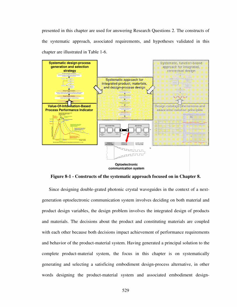
529
presented in this chapter are used for answering Research Questions 2. The constructs of
the systematic approach, associated requirements, and hypotheses validated in this
chapter are illustrated in Table 1-6.
Systematic design-process generation and selection
strategy
Value-Of-Information-Based Process Performance Indicator
Design catalogs phenomena and associated solution principles
Systematic, function-based approach for integrated,
conceptual design
Systematic mapping of classified phenomena and solution principles from multiple scales and disciplines to multilevel function structures
Creating multilevel function structures based on functional analysis, abstraction and synthesis
Ex,in
Mx,in
Ex,in
System boundary
System function x Exyz,out
System function z
System function y
Ey,in
Sz,i n
Mx,in Sub-system function xx
Ex,out
Sub-system function xy
Sz,in
Ey,in Material function yx
Eyz,out
Material function zx
Sub-system boundarySystem level
Sub-system level
Material level
Clarification of Task
Multilevel Function Structure Selection
Concept Selection
Concept
Principle
Phenomenon
Function
Pheno-menon
Scale Properties Applications
"Monolithic" materials
- Metals Compared to a ll other classes of material , metals are stif f, strong and tough, but
they are heavy. They have rel atively hi gh melti ng points. Only one metal - gold - is
chemically stable as a metal . Metals are d uctile, all owing them to be shaped by
roll ing, forgin g, drawi ngn and extrusion. They are easy to machine with precision, and they can be j oined i n many different ways. Iron an d nickel are transit ional
metals involving both metallic and covalent bonds, and tend to be less d uctile than
other meta ls. However, metals conduct electricity well , ref lect light a nd are
completely opaque. Pri mary producti on of metals is ene rgy i ntensive. Man y
require at least twice as much energy per un it weight than commodity polymers.
But, metals can general ly be recycl ed and the energy required to do so is much l ess than that requried for primary production. Some are toxi c, others are so inert
that they can be i mpl anted in the human body.
- Al uminum-, copper-,
magnesi um-, nickel-, steel -,
ti tanium-, zinc-al loys
- Carbon-, stainles-, … steels
- Amorphous meta ls, …
Ela
sti
c/in
ela
sti
c d
efo
rmat
ion
(te
ns
ion
, c
om
pre
ssi
on
, be
nd
ing
, sh
ear
, to
rsio
n,
bu
ckl
ing
, fr
actu
re, c
utt
ing
, in
ver
sio
n, e
xtr
usi
on
,
Characteristics
Solution Principle
- Pol ymers
From a macroscale, monolith ic materials are referred to as matter, i.e., the substance of which physi cal objects are composed.
Polymers feature an immense range of form, color, surface fini sh, transluce ncy, transparency, toughness a nd f lexibility. Ease of moldi ng all ows sh apes that i n
other mate ri als could only be bui lt up by expensive assembly methods. Their
excellent workabili ty all ows the mol ding of complex forms, al lowing cheap
manufacture of i ntegrated components that previously were made b y assembling
many parts. Many polymers are cheap both to b uy and shape. Most resist water,
acids and alkali s well, though organic so lvents attack some. All are light and ma ny are fl exibl e. Their properties change rapidly with temperature. Even at room
temperature many creep and when cooled the y may become brit tl e. Pol ymers
generall y are sensiti ve to UV radiation and to strongly oxidi zing environments.
- Thermosplastic p olymers: ABS, Cellulose, Ionomers,
Nyl on/PA, PC, PEEK, PE,
PMMA, POM, PP, PS, PTFE,
tpPVC, tpPU,
PET/PETE/PBT
- Thermosett ing pol ymers: Epoxy, Phenolic, Pol yester,
tsPU, tsPVC
- El astomers: Acrylic
machining.
Honeycomb-cor e
sandwiches
- In-plane honeycombs Core cel l axes of in-plane honeycomb cores are oriented paral lel to the face-
sheets. They provide potenti als for decreased conductivity and f luid f low within
cells. Relative densit ies range from 0.001 to 0.3. Their densif icatio n strain can be approximated as:
Their relat ive st iffness can be approximated as:
Their relat ive stren gth can be ap proximated as:
- Prismati c-, square-,
chiracal-, etc. core in-plane
honeycombs
- Out-o f-plane honeycombs Core cel l axes of out-of-pl ane honeycomb cores are oriented perpendicular to
face-sheets. They provide potentials for decreased conducti vi ty. Relative densities
range from 0.001 to 0.3. Their densif ication strain can be approxi mated as:
Their relat ive st iffness can be approximated as:
Their relat ive stren gth can be ap proximated as:
- Hexagonal-, sqau re-, etc.
core put-of-plane
honeycombs
Fiber-composite s
- Conti nuous fi ber
composites
Continuous f iber composites are composi tes wi th highest st if fness and strength.
They are made of continuous fibers usuall y embedd ed in a thermosetting resin. The f ibers carry the mechani cal loads whi le the matrix material transmits loads to
the f ibers and provides ducti lity an d toughness as well as protecting the fibers
from damage caused by h andling or the environmen t. I t is the matrix material that
l imi ts the service temperature and proce ssing conditio ns. On mesoscales, the
propert ies can be strongly i nfluenced by the choice of f iber and matrix and the
way i n which these are combined: f iber-resin ratio, fi ber length, fi ber orientation, l aminate thickness and the presence of fiber/resi n coupling agents to improve
bondi ng. The strength of a composite is increased by raising the f iber-resin ratio,
and orienting the f ibers parall el to the l aoding di rection. Increased lami nate
thickness leads to reduced composite strength and modulus as there is an
i ncreased likelihood of entrapped voids. Environmental conditi ons affect the
performance of composites: fat igue l oading, moisture and heat all
reduce allowable strength. Polyesters are the most most wi dely used matri ces as they offer reasonable propertie s at relati vely low cost. The superior propert ies of
epoxies and the termperature performance of polyi mide s can justify their use in
certa in appli cations, but they are expensive.
- Glass f ibers [high strength
at low cost], polymer f ibers (organic (e.g., Kevl ar) or
anorganic (e.g., Nylon,
Polyester)) [reasonable
properties at relatively l ow
cost], carbon fibe rs [very high
strength, st if fness and low density]
- Strands, fil aments, fibers,
yarns (twisted strands),
rovi ngs (bundled strands)
- Nonwoven matt ings,
weaves, braids, knits, other
- Disco ntinuous fiber
composites
Polymers rei nforced with chopped polymer, wood, glass o r carb on f ibers are
referre d to as di scontinuous f iber composites. The longer the fi ber, the more
eff ici ent is the reinforcement at carryi ng the appli ed loads, but shorter fi bers are easier to process an d hence cheaper. Hence, f iber length and material are the
governing design variables. However, fibrous core composites fea ture shape
f lexibili ty and relati vely high bendi ng sti ffness at low densi ty.
- Glass f ibers, polymer fibers
(organic (e.g., Kevl ar) or
anorganic (e.g., Nylon, Polyester)), carbon f ibers
Me
so
sc
ale
Ela
sti
c/i
ne
lasti
c d
efo
rm
ati
on
(te
nsio
n,
co
mp
ressio
n, b
en
din
g, s
he
ar,
to
rsio
n, b
uc
kli
ng
, fr
ac
ture
, cu
ttin
g,
inv
ers
ion
, e
xtr
us
ion
, d
raw
ing
,
flo
w)
Honeycomb-core sandwiches take thei r name from their visu al resemblance to a bee's honeycomb. W ith controlla ble core di mensions
and topologies on mesoscale s, they freature relatively high stif fness and yield strength at low d ensi ty. Larg e compressive strai ns are achievable at nominal ly constant stress (before the material compa cts), yieldi ng a potentially hi gh energy absorpti on capacity. Honeycomb-
core sandwiches have acceptabl e structural performance a t rel atively low costs with useful combinations of thermophysical and
mechani cal properti es. Usually, they provide benefits with respect to mult iple use.
The combin ation of polymers or other ma trix materi als with f ibers has gi ven a range of light materi als with st iffness and strength
comparable to that of metals. Commonly, resin materi als are e poxi es, pol yesters and vinyls. Fibers are much stronger and stif fer than
thei r equivalent in bulk form because the drawing process by they are made orients the polymer ch ains along the fi ber axis or re duces the
density of defects.
−≈
s
D ρ
ρε 4.11
31 rel
sE
Eρ≈
rel
ys
y ρσ
σ5.0≈
rel
sE
Eρ1≈
rel
ys
y ρσ
σ1≈
−≈
s
D ρ
ρε 4.11
Output
Input
Mechanical
Energy
(In)elastic de-formationInertia…
Electrostric-tion…
Magnetostric-tion…
Impact…
Friction…
Pressure change…
Dislocation hardening…
Electrostatic
Energy
Electric field…
Interference…
Hall-effect…
Electrostric-tion…
Photostric-tion…
Electrical resistance…
Galvanic element…
Magnetostatic
Energy
Magnetic field…
Oscillating circuit…
Ferromag-netism…
Magneto-striction…
Farraday-effect…
Eddy current…
Sound
Energy
Pressure wave…
Electrostric-tion…
Magnetostric-tion…
Reflection …
Noise dam-ping…
Elasticity…
Light
Energy
Electromag-netic radiation…
Photostric-tion…
Absorption…
Refraction…
Thermolumi-nescence…
Photoeffect…
Thermal
Energy
Thermal expansion…
Thermoelectricity…
Curie-Weiss law…
Pyro-electricity…
Convection…
Phase trans-formation…
Molecular
Energy
Exothermic reaction…
Molecular dipoloe…
Fluores-cence…
CombustionConductivity…
Adhesion…
Light
Energy
Thermal
Energy
Molecular
Energy
Mechanical
Energy
Electrostatic
Energy
Magnetostatic
Energy
Sound
Energy
Design Variable
Ex
pe
cte
d O
vera
ll P
ayo
ff
Expected payoff usingdesign process alternative 1(global information)
Expected payoff using refined design process alternative 2(global information)
Payoff 2
Decision 1 Decision 2
Payoff 1
Process Performance Indicator 1
Expected payoff using most accurate physical or simulation models(local information)
Process Performance Indicator 2
Decisions based on predicted behavior using design process alternatives 1, 2, 3, etc.
Process Performance Indicator 3
Expected payoff using refined design process alternative 3(global information)
Payoff 3
Decision 3
Evaluation of design-process alternatives and additional modeling potential
through a value-of-information-based Process Performance Indicator
Systematic generation of design-process alternatives based on
principles from information economics
Design-Process Evaluation
Design-Process Selection
Concept Exploration and Selection
Template-based decision-centric embodiment design
2) S elect and Evaluate Simple Initial
Design Process Alte rnative.
4) Evalua te most truthful design process
alterna tive ava ilable.
Step 7: Select satisficing embodiment
design process alt ernative.
1) Formula te Decision Using
Compromi se DSP.
3) Determine Decision Point by Solving
cDSP for Maximum Payoff.
High Process Per-formance Indicator
Low Process Performance Indicator
5) Evaluate Process Performance Indicator
S imple Initial Design-Process Alternative .6) Refine Design-Process and
Repeat Steps 3 Through 5.
…
Optoelectronic communication system
Systematic approach for integrated product, materials,
and design-process design
Template-based decision-centric concept exploration accounting for uncertainty and
complexity of multilevel and multiscale design
Evaluation of design-process alternatives and value of additional multiscale modeling based on
Process Performance Indicator
Multilevel Function Structure Selection
Clarification of Task
Design-Process Design
Embodiment Design
Design-Process Selection
Concept Selection
Creating multilevel function structures based on
functional analysis, abstraction and synthesis
Systematic mapping of classified phenomena and solution principles from multiple scales and
disciplines to multilevel function structures
Systematic generation of multiscale design-process alternatives based on a value-of-
information-based strategy
Signal(information
input)
Modulator Source(carrier)
Detector Signal-processor
Signal(information
output)
Input- Output-
coupling
TRANSMITTER RECEIVER
a)
b)
NORMAL
WAVEGUIDE
OPTICAL
COUPLER
SLOW-LIGHT
WAVEGUIDE
Figure 8-1 - Constructs of the systematic approach focused on in Chapter 8.
Since designing double-grated photonic crystal waveguides in the context of a next-
generation optoelectronic communication system involves deciding on both material and
product design variables, the design problem involves the integrated design of products
and materials. The decisions about the product and constituting materials are coupled
with each other because both decisions impact achievement of performance requirements
and behavior of the product-material system. Having generated a principal solution to the
complete product-material system, the focus in this chapter is on systematically
generating and selecting a satisficing embodiment design-process alternative, in other
words designing the product-material system and associated embodiment design-
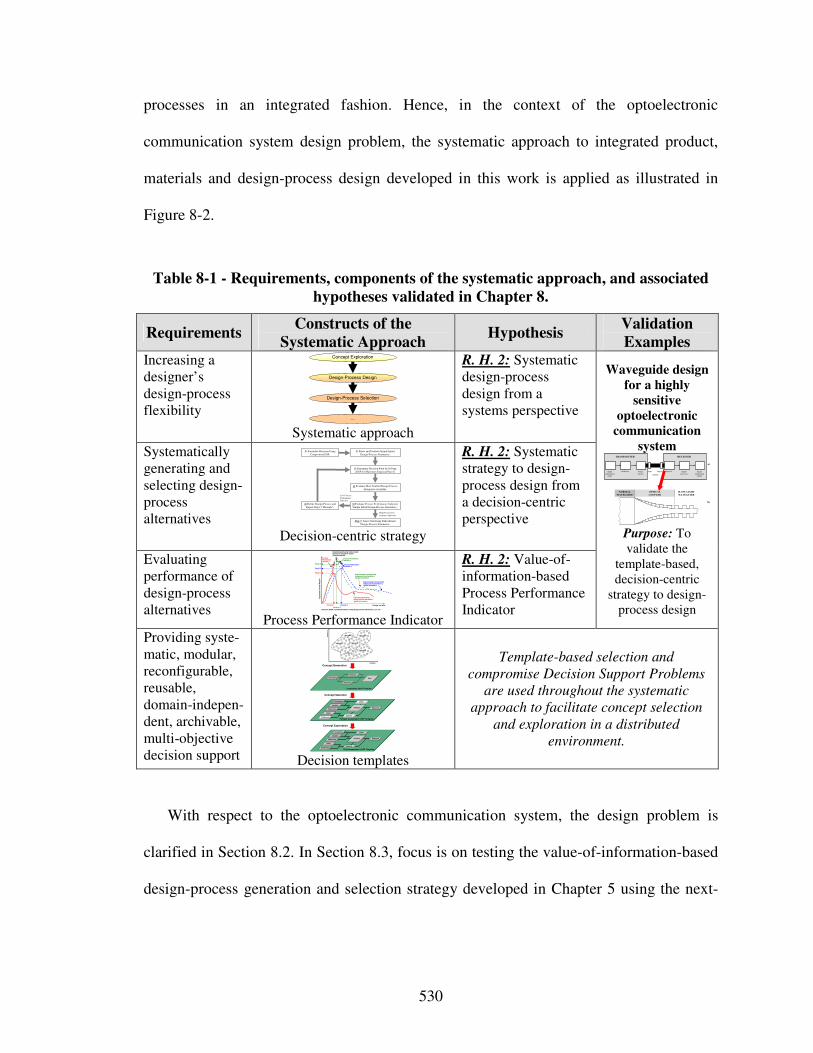
530
processes in an integrated fashion. Hence, in the context of the optoelectronic
communication system design problem, the systematic approach to integrated product,
materials and design-process design developed in this work is applied as illustrated in
Figure 8-2.
Table 8-1 - Requirements, components of the systematic approach, and associated
hypotheses validated in Chapter 8.
Requirements Constructs of the
Systematic Approach Hypothesis
Validation
Examples Increasing a designer’s design-process flexibility
Design-Process Design
…
Design-Process Selection
Concept Exploration
Systematic approach
R. H. 2: Systematic design-process design from a systems perspective
Systematically generating and selecting design-process alternatives
2) Select and Evaluate Simple Initial
Design-Process Alternative.
4) Evaluate Most Truthful Design-Process
Alternative Available.
Step 7: Select Satisficing Embodiment
Design-Process Alternative.
1) Formulate Decision Using
Compromise DSP.
3) Determine Decision Point by Solving
cDSP for Maximum Expected Payoff.
High Process Per-
formance Indicator
Low Process
Performance
Indicator
5) Evaluate Process Performance Indicator
Simple Initial Design-Process Alternative .
6) Refine Design-Process and
Repeat Steps 3 Through 5.
Decision-centric strategy
R. H. 2: Systematic strategy to design-process design from a decision-centric perspective
Evaluating performance of design-process alternatives
Design Variable
Ex
pe
cte
d O
ve
rall
Pa
yo
ff
Expected payoff usingdesign process alternative 1(global information)
Expected payoff using refined design process alternative 2(global information)
Payoff 2
Decision 1 Decision 2
Payoff 1
Process Performance Indicator 1
Expected payoff using most accurate physical or simulation models(local information)
Process Performance Indicator 2
Decisions based on predicted behavior using design process alternatives 1, 2, 3, etc.
Process Performance Indicator 3
Expected payoff using refined design process alternative 3(global information)
Payoff 3
Decision 3 Process Performance Indicator
R. H. 2: Value-of-information-based Process Performance Indicator
Waveguide design
for a highly
sensitive
optoelectronic
communication
system
Signal
(informationinput)
Modulator Source
(carrier)
Detector Signal-
processor
Signal
(informationoutput)
Input- Output-
coupling
TRANSMITTER RECEIVER
a)
b)
NORMAL
WAVEGUIDE
OPTICAL
COUPLER
SLOW-LIGHT
WAVEGUIDE
Purpose: To validate the
template-based, decision-centric
strategy to design-process design
Providing syste-matic, modular, reconfigurable, reusable, domain-indepen-dent, archivable, multi-objective decision support
Concept Generation
Concept Selection
Concept Exploration
Alternatives Rank
Instantiated sDSP Template
Importance
Attributes
Goals
Preferences
Variables
Parameters
Constraints
Response
Objective
Analysis
Driver
Fully Instantiated cDSP Template
Goals
Preferences
Variables
Parameters
Constraints
Response
Objective
Analysis
Driver
Partially Instantiated cDSP Template
Att
rib
ute
2
Attribute 1
Concept 2
Concept 5
Concept 1 Concept 3
Concept 6
Concept 4
Decision templates
Template-based selection and
compromise Decision Support Problems
are used throughout the systematic
approach to facilitate concept selection
and exploration in a distributed
environment.
With respect to the optoelectronic communication system, the design problem is
clarified in Section 8.2. In Section 8.3, focus is on testing the value-of-information-based
design-process generation and selection strategy developed in Chapter 5 using the next-
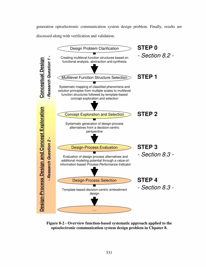
531
generation optoelectronic communication system design problem. Finally, results are
discussed along with verification and validation.
Template-based decision-centric embodiment design
Evaluation of design-process alternatives and
additional modeling potential through a value-of-
information-based Process Performance Indicator
Multilevel Function Structure Selection
Design Problem Clarification
Design-Process Evaluation
Design-Process Selection
Concept Exploration and Selection
Co
nc
ep
tual
Desig
n
-R
esearc
h Q
ues
tio
n 1
- Creating multilevel function structures based on
functional analysis, abstraction and synthesis
Systematic mapping of classified phenomena and
solution principles from multiple scales to multilevel
function structures followed by template-based
concept exploration and selection
De
sig
n-P
roc
ess D
esig
n a
nd
Co
nce
pt
Exp
lora
tio
n
-R
esea
rch
Qu
es
tio
n 2
-STEP 0
STEP 3
STEP 1
STEP 4
STEP 2
…
- Section 8.2 -
- Section 8.3 -
- Section 8.3 -
Systematic generation of design-process
alternatives from a decision-centric
perspective
Figure 8-2 - Overview function-based systematic approach applied to the
optoelectronic communication system design problem in Chpater 8.
532
8.2 Step 0 – Clarifying the Design Problem and Modeling Assumptions
The design problem is clarified first in Section 8.2.1. Then, in Section 8.2.2,
fundamental modeling assumptions are addressed. Finally, in Section 8.2.3, modeling
assumptions specific to the optical coupler and slow-light waveguide are addressed.
8.2.1 Clarifying the Design Problem
Consider the design of an optoelectronic communication system, as illustrated in
Figure 8-3, for specialized applications, such as long-distance data transmission,
operating at a specific wavelength and low receiver intensity. In this context,
optoelectronics deals with the interaction of electronic processes with light and optical
processes. Devices in which such interaction can suitably take place, usually
accompanied by an energy conversion process (e.g., from electrical to optical, and vice
versa), are called optoelectronic devices. Such devices are conveniently made with
semiconductors. In Figure 8-3 a), a simple optoelectronic communication system,
consisting of transmitter, coupling and receiver subsystems, is shown. Dimensions of
system components are in the micrometer range.
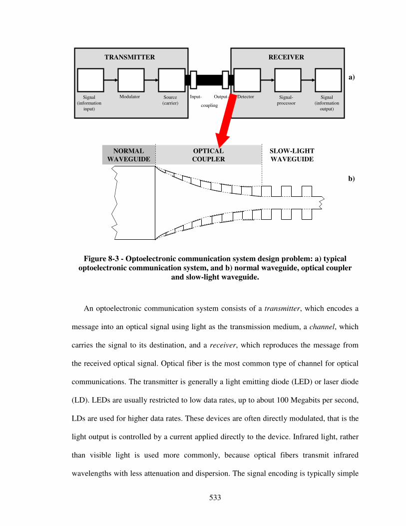
533
Signal
(information
input)
Modulator Source
(carrier)
Detector Signal-
processor
Signal
(information
output)
Input- Output-
coupling
TRANSMITTER RECEIVER
a)
b)
NORMAL
WAVEGUIDE
OPTICAL
COUPLER
SLOW-LIGHT
WAVEGUIDE
Figure 8-3 - Optoelectronic communication system design problem: a) typical
optoelectronic communication system, and b) normal waveguide, optical coupler
and slow-light waveguide.
An optoelectronic communication system consists of a transmitter, which encodes a
message into an optical signal using light as the transmission medium, a channel, which
carries the signal to its destination, and a receiver, which reproduces the message from
the received optical signal. Optical fiber is the most common type of channel for optical
communications. The transmitter is generally a light emitting diode (LED) or laser diode
(LD). LEDs are usually restricted to low data rates, up to about 100 Megabits per second,
LDs are used for higher data rates. These devices are often directly modulated, that is the
light output is controlled by a current applied directly to the device. Infrared light, rather
than visible light is used more commonly, because optical fibers transmit infrared
wavelengths with less attenuation and dispersion. The signal encoding is typically simple
534
intensity modulation, although historically optical phase and frequency modulation have
been demonstrated. Receivers use p-i-n diodes or other semiconductor devices as the
optical-electrical converter. The receiver is typically coupled with an amplifier to produce
a digital signal in the electrical domain from the incoming optical signal, which may be
attenuated and distorted by passing through the channel. Further signal processing may
also be applied before the data is passed on.
Since the design of a next-generation optoelectronic communication system for
specialized applications operating at specific wavelengths and low receiver intensity is
required, enhanced means for signal propagation and dispersion control must be
provided. Typical optical propagation and dispersion control components not only cause
additional cost or complexity especially in an extreme environment installation or
military application, but also significantly decrease signal-to-noise ratios in the signal by
amplifying noise. Specifically, noise is amplified because signal processing is typically
not performed before amplification. Hence, based on the phenomena design catalog given
in Table 4-3, the photonic crystal phenomenon is leveraged to design waveguides, based
on advanced multifunctional materials, coupled to a detector in a next-generation
optoelectronic communication system – a promising principal solution to the solution-
neutral problem statement:
Providing enhanced means for signal propagation and dispersion control for a next-
generation optoelectronic communication system in the context of specialized
applications operating at specific wavelengths and low receiver intensity.
535
Photonic crystal waveguides offer unprecedented control over the propagation and
dispersion of light. However, there are significant difficulties encountered when coupling
light into these waveguides from traditional optical waveguides. Particularly, when
making a transition from one type of waveguide to another, there will inevitably be
reflections at the transition. These reflections are undesirable, as they reduce the amount
of light that enters the second waveguide. An imperfect but illuminating analogy would
be a broad river that is abruptly forced through a narrow channel. One would expect there
to be 'backup' of water behind the transition area. The proposed solution is a tapered
waveguide, which will “ease” the transition between the two waveguides, and thereby
minimize reflections. To reuse the river analogy, it would be similar to gradually tapering
in the river banks in order to force most of the water to continue flowing in the narrow
channel.
Also, when “squeezing” light from traditional into photonic crystal waveguides
operating in a “slow-light” region, it is important to slow the group velocity of light down.
Operating in a slow-light region is useful because it i) increases interaction of the light
with the material in for example a photodetector, and ii) enhances nonlinearities,
tunabilities, gain and other effects. In this context, periodic waveguides are both useful
and challenging because the periodic waveguide has a slow-light band edge frequency,
for which i) the group velocity of light slows down, but, also ii) more and more light is
reflected as it approaches this certain band edge frequency. Also, as the group velocity of
light decreases, impedance mismatch increases and a longer taper is usually required to
achieve the same light transmission [511].
Therefore, one is most interested in the design of:
536
i) an optical coupler, i.e., a tapered double-grated photonic crystal waveguide, that
couples power between a passive uniform “normal” waveguide, in the following
referred to as a normal waveguide, and a passive uniform double-grated “slow-
light” photonic crystal waveguide, referred to as a slow-light waveguide in the
following, and
ii) the design of the slow-light waveguide itself,
to control propagation (transmission), dispersion (group velocity) of light, and length of
the optical coupler. The optical coupler and slow-light waveguide, coupled to a normal
waveguide on the one side and photodetector on the other side, are illustrated in Figure
8-3 b) and described in the following.
The photonic crystal optical coupler and slow-light waveguide are to be designed to
increase transmission while slowing the group velocity of light and minimizing length of
the optical coupler. Designing the photonic crystal optical coupler and slow-light
waveguide in such a way increases efficiency of the overall optoelectronic
communication system and interaction strength between normal waveguides and other
system components, particularly photodetectors. Typically, a slow-light waveguide is
optically coupled to a photodetector to allow the generation of a fast enough current and
thereby switching at a high bandwidth. However, integrating a photodetector with the
optical coupler and slow-light waveguide is left for future work. In this dissertation, the
photodetector is not designed but assumed to be selected during the later stages of
embodiment and detail design. However, a photodetector’s dimensions constrain
dimensions of the waveguide, reflected in the decision formulation for the photonic
crystal waveguide.
537
In summary, in this dissertation photonic crystal based devices are designed to realize
the core functionalities of a next-generation optoelectronic communication system
operating at specific wavelengths and low receiver intensity. Hence, through integrated
design of products and materials, the need for filter and amplifier components is reduced
and the potential for using faster processing optical circuits is increased. Having
identified this concept, focus in this chapter is on designing embodiment design-
processes for rapid concept exploration from a decision-centric perspective as described
in Chapter 5. Finally, embodiment design results of the optical coupler and slow-light
double-grated photonic crystal waveguide are generated.
Having clarified the design problem, fundamental modeling assumptions are
addressed in Section 8.2.2. Then, in Section 8.2.3, modeling assumptions specific to the
optical coupler and slow-light waveguide are addressed.
8.2.2 Fundamental Modeling Assumptions
A waveguide is a structure which guides waves, such as electromagnetic, light, or
sound waves. Waveguides are passive or quasi-passive optical components
monolithically integrated with the active components: sources, detectors, modulators and
electronic devices. Conceivably one could use optical fibers, but, the application of these
would be limited from both the point of view of integration and that of functionality.
Guided wave components are required for routing optical signals on a chip and also for
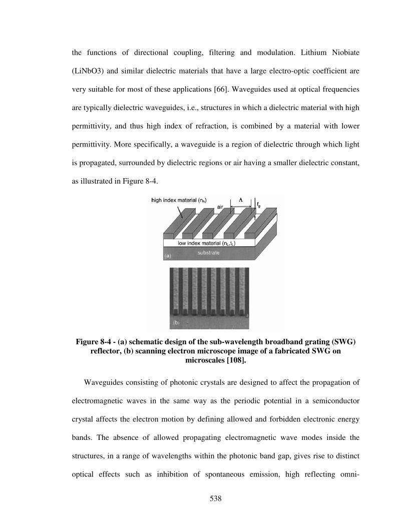
538
the functions of directional coupling, filtering and modulation. Lithium Niobiate
(LiNbO3) and similar dielectric materials that have a large electro-optic coefficient are
very suitable for most of these applications [66]. Waveguides used at optical frequencies
are typically dielectric waveguides, i.e., structures in which a dielectric material with high
permittivity, and thus high index of refraction, is combined by a material with lower
permittivity. More specifically, a waveguide is a region of dielectric through which light
is propagated, surrounded by dielectric regions or air having a smaller dielectric constant,
as illustrated in Figure 8-4.
Figure 8-4 - (a) schematic design of the sub-wavelength broadband grating (SWG)
reflector, (b) scanning electron microscope image of a fabricated SWG on
microscales [108].
Waveguides consisting of photonic crystals are designed to affect the propagation of
electromagnetic waves in the same way as the periodic potential in a semiconductor
crystal affects the electron motion by defining allowed and forbidden electronic energy
bands. The absence of allowed propagating electromagnetic wave modes inside the
structures, in a range of wavelengths within the photonic band gap, gives rise to distinct
optical effects such as inhibition of spontaneous emission, high reflecting omni-
539
directional mirrors and low-loss-waveguiding among others. In this context, a complete
photonic band gap is a range of frequencies in which there are no propagating (real
wavevector k) solutions of Maxwell’s equations in the band gap. Thus, the crystal can
perform as a kind of perfect optical insulator, which can confine light losslessly around
sharp bends, in lower-index media, and within wavelength-scale cavities.
Since the basic physical phenomenon is based on diffraction, the periodicity of the
photonic crystal structure has to be in the same length-scale as half the wavelength of the
electromagnetic waves, i.e., the length-scale is proportional to the wavelength of light in
the band gap. When the wavelength in these periodically structured electromagnetic
media is on the order of periodicity, they are referred to as photonic crystals. However,
when the wavelength is much shorter than periodicity, these composite materials are
referred to as metamaterials. Photonic crystals or metamaterials are dielectric materials
that have been fabricated to have periodic optical properties in one, two or three spatial
dimensions, i.e., the permittivity is a periodic function of space in one, two, or three
dimensions.
For example, a distributed Bragg reflector (DBR) mirror is composed of alternating
high- and low-refractive index materials. Therefore, it exhibits high reflectivity when
layer thicknesses are equal to a quarter-wavelength in the medium. Backward-
propagating waves then tend to interfere constructively, forward-propagating waves tend
to interfere destructively. This results in high normal-incidence reflectivity over some
range of frequencies.
Photonic band gaps are usually plotted in band diagrams, i.e., dispersion relations, in
which the temporal frequency ω is plotted over the wavenumber k, as illustrated in Figure
540
8-5 for the first mode. As described above, for most wavelengths the light beam can
propagate through the photonic crystal without scattering (which would cancel
coherently), but, for some wavelengths (approximately twice the lattice constant a
(periodicity)), no light can propagate, i.e., a photonic band gap exists.
For example, to form such a waveguide filter, it is essential to employ techniques that
will effectively and selectively create regions of varying refractive index through specific
fabrication processes. The refractive index difference between the high and low index
materials determines the bandwidth and modulation depth. The larger difference in
refractive indices gives rise to wider reflection bands. The low index layer under the
grating is critical for the broadband mirror effect. The reflection is sensitive to design
parameters including the grating period, grating thickness, duty cycle (ratio of the width
of the high index material with respect to the grating period), refractive index of materials
and thickness of the low index layer underneath the grating.
In this context, photonic crystals are periodically structured electromagnetic media
with periodic modulation of the refractive index, generally possessing photonic band
gaps or band edges, i.e., ranges of frequency in which light cannot propagate through the
structure. Breaking the photonic crystal symmetry by introducing discontinuities allows
control of light on a subwavelength scale. Therefore, photonic crystal devices may be up
to one million times smaller than traditional integrated optical devices [66]. At the same
time, they feature unseen low transmission losses and high operational bandwidth, or
wavelength selective functionalities. Potential applications for photonic crystal devices
are high-Q laser cavities that compensate for dispersion by matching group velocities,
polarization splitters, detectors, optical couplers to glass fibers and conventional
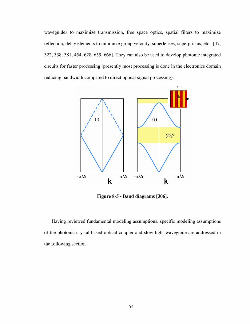
541
waveguides to maximize transmission, free space optics, spatial filters to maximize
reflection, delay elements to minimize group velocity, superlenses, superprisms, etc. [47,
322, 338, 381, 454, 628, 659, 666]. They can also be used to develop photonic integrated
circuits for faster processing (presently most processing is done in the electronics domain
reducing bandwidth compared to direct optical signal processing).
Figure 8-5 - Band diagrams [306].
Having reviewed fundamental modeling assumptions, specific modeling assumptions
of the photonic crystal based optical coupler and slow-light waveguide are addressed in
the following section.
542
8.2.3 Optical Coupler and Slow-Light Waveguide Modeling Details
In the context of the design problem clarified in Section 8.2.1, previous research
efforts on designing photonic crystal based devices have mostly been focused on cases
operating far from any band edge (where the group velocity is not small), on non-tapered
grated waveguides [43, 248, 349, 514], linear (constant-rate) grated tapers [61, 123, 250,
305, 419, 471, 509, 660, 749], families of quadratic shape grated waveguides [170, 321,
766], or linear, quadratic and general polynomial shapes of tapered uniform waveguides
[140, 199, 382, 427, 615, 627, 716]. Also, previous work is characterized by a small
number of design variables and single-objective optimization. The nominal optimum
obtained performs well only under nominal conditions. However, decision-making in the
context of photonic crystals relies on delicate interference effects and therefore involves
parameter variations deviating from nominal conditions “destroying” any nominal
optimum. To not rely on single-point solutions, the robust design of photonic crystal
waveguides has been investigated including manufacturing errors and other uncertainties
[510]. However, the focus is on non-deterministic, but still single-objective optimization,
mostly based only one or two design variables. Therefore, in this work, the focus is on
multiobjective decision making using utility-based compromise Decision Support
Problems to achieve the robust design of an optical coupler and slow-light waveguide.
In this work, the optical coupler is considered as a quasi-periodic structure of length L
that is parameterized by two taper shape functions f(al) and f(au), i.e., functions of an
lower and upper shape function parameter al and au, in the form of:
( )
−
−−+= 1122)( 211
a
L
xbbbaf Equation 13
543
The taper shape functions are constrained in their starting and final points, where they
match the cross sections of the normal and slow-light waveguide respectively.
Based on the taper shape functions, periodicity, and number of periods, the magnitude
of the transmission from an incoming light wave coupled from the normal into the slow-
light waveguide is evaluated. Also, length L of the optical coupler is evaluated based on
the shape functions and periodicity. As a measure of group velocity in these early stages
of design, distances to the band edge in bandgap plot are evaluated for specific
periodicity a and number of periods np. The periodicity a is varied gradually by spreading
the grating “blocks” of length d2 apart thereby decreasing the distance d1 between them.
Also, the width of the normal waveguide and hence “starting” width of the optical
coupler b1 is varied to determine suitable input waveguide dimensions. Typically, an
optical fiber with a width of 10 µm is used as a normal waveguide. However, input could
also be any other tapered or non-tapered waveguide.
NORMAL
WAVEGUIDE
OPTICAL
COUPLER
SLOW-LIGHT
WAVEGUIDE
L
d1 d2
a
wg
2b22b1 f(au) f(al)
Figure 8-6 - Geometry optical coupler and slow-light waveguide.
Because the waveguide incorporates a gradually changing photonic crystal, it features
a photonic band gap that is used for filtering light of unwanted frequencies. For certain
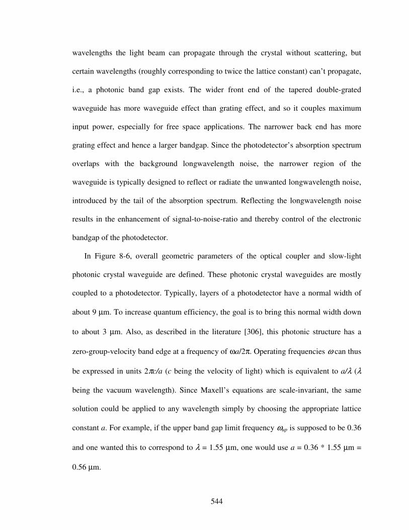
544
wavelengths the light beam can propagate through the crystal without scattering, but
certain wavelengths (roughly corresponding to twice the lattice constant) can’t propagate,
i.e., a photonic band gap exists. The wider front end of the tapered double-grated
waveguide has more waveguide effect than grating effect, and so it couples maximum
input power, especially for free space applications. The narrower back end has more
grating effect and hence a larger bandgap. Since the photodetector’s absorption spectrum
overlaps with the background longwavelength noise, the narrower region of the
waveguide is typically designed to reflect or radiate the unwanted longwavelength noise,
introduced by the tail of the absorption spectrum. Reflecting the longwavelength noise
results in the enhancement of signal-to-noise-ratio and thereby control of the electronic
bandgap of the photodetector.
In Figure 8-6, overall geometric parameters of the optical coupler and slow-light
photonic crystal waveguide are defined. These photonic crystal waveguides are mostly
coupled to a photodetector. Typically, layers of a photodetector have a normal width of
about 9 µm. To increase quantum efficiency, the goal is to bring this normal width down
to about 3 µm. Also, as described in the literature [306], this photonic structure has a
zero-group-velocity band edge at a frequency of ωa/2π. Operating frequencies ω can thus
be expressed in units 2πc/a (c being the velocity of light) which is equivalent to a/λ (λ
being the vacuum wavelength). Since Maxell’s equations are scale-invariant, the same
solution could be applied to any wavelength simply by choosing the appropriate lattice
constant a. For example, if the upper band gap limit frequency ωup is supposed to be 0.36
and one wanted this to correspond to λ = 1.55 µm, one would use a = 0.36 * 1.55 µm =
0.56 µm.
545
In order to achieve the design goals with respect to transmission, length of the optical
coupler and group-velocity of light, the photonic crystal waveguides are designed
involving parameters of the grating at microscales and taper at macroscale to tailor
“effective” optical properties of the multifunctional photonic crystal waveguide
component in the optoelectronic system context. In order to do so, more or less complex
design-process alternatives can be generated and selected, such as effective index models,
coupled mode theory models, Fourier modal models, or very detailed finite difference
models. In this context, the goal is to show how to increase a designer’s design-process
flexibility by using the value-of-information-based design-process generation and
selection strategy developed in this dissertation. Since the decision on an integrated
product and material system concept has already been made, modularity of the developed
systematic approach to the integrated design of product and material concepts is
leveraged by omitting Steps 1 and 2. The principal solution consisting of the photonic
crystal optical coupler and slow-light waveguide is thus input to Step 3 of the systematic
approach.
8.3 Steps 3 and 4 – Design-Process Generation and Selection
In this section, the focus is on the systematic generation and selection of design-
process alternatives based on principles from information economics in the context of
designing double-grated photonic crystal waveguides. This involves Steps 3 and 4 of the
546
systematic approach presented in Figure 8-2. Various design-process alternatives are
instantiated by replacing analysis blocks in the template-based cDSP formulation
developed in Section 8.3.1. The goal is to find a satisficing design-process alternative in
the context of the optoelectronic containment system example clarified in Section 8.2.
These design-process alternatives and the additional modeling potential are then
evaluated through a value-of-information-based Process Performance Indicator from a
decision-centric view of design, i.e., based on the fundamental assumption that analysis
models are used to make better decisions. Hence, design-process generation is driven by
the need to improve decision making capability through a value-of-information-based
design-process design strategy, as illustrated in Figure 8-7.
Using the value-of-information-based design-process design strategy described in
detail in Chapter 5, the general steps for design-process generation and selection are
presented again in Figure 8-8 for the reader’s convenience. Step A relates to formulating
the design decision using the compromise DSPs as discussed in Section 8.3.1. In Step B,
a least complex initial design-process alternative is selected and evaluated as described in
Section 8.3.2. In Step C, the decision point is determined by solving for maximum
payoff, as outlined in Section 8.3.3. In Step D, the most truthful design-process
alternative, as defined in Section 5.3, is evaluated, as discussed in Section 8.3.4. In Step
E, the resulting Process Performance Indicator is evaluated, and a decision has to be
made to whether select this design-process alternative (Step G), or refine the given
design-process alternative (Step F), as outlined in the Sections 8.3.5, 8.3.6, and 8.3.7.
547
Evaluation of design-process alternatives and additional modeling potential through a value-of-information-based Process Performance Indicator
Systematic generation of design-process alternatives from a decision-centric perspective
Design-Process Evaluation
Design-Process Selection
Concept Exploration and Selection
Template-based decision-centric embodiment design
Design Variable
Ex
pe
cte
d O
ve
rall
Pa
yo
ff
Expected payoff usingdesign process alternative 1(global information)
Expected payoff using refined design process alternative 2(global information)
Payoff 2
Decision 1 Decision 2
Payoff 1
Process Performance Indicator 1
Expected payoff using most accurate physical or simulation models(local information)
Process Performance Indicator 2
Decisions based on predicted behavior using design process alternatives 1, 2, 3, etc.
Process Performance Indicator 3
Expected payoff using refined design process alternative 3(global information)
Payoff 3
Decision 3
…
Go als
P referenc es
Vari abl es
Pa ra meters
Con strain ts
Re spo nse
Obj ect i ve
Fully Instantia ted cDSPTemplate
D ri ver
A nal ysi s
Go als
P referenc es
Vari abl es
Pa ra meters
Con strain ts
Re spo nse
Obj ect i ve
Fully Instantia ted cDSPTemplate
D ri ver
A nal ysi s
P1 P2 P3
P6
P9P8P7
P4 P5
Validation
X1 Y1
X2 Y2
X1 Y1
X2 Y2
X1
Y1
X2 Y2
Analysis i
Go als
P referenc es
Vari abl es
Pa ra meters
Con strain ts
Re spo nse
Obj ect i ve
F ul l y In s tan t i a ted c D S P T e mp l a te
D ri ver
A nal ysi s
Go als
P referenc es
Vari abl es
Pa ra meters
Con strain ts
Re spo nse
Obj ect i ve
F ul l y In s tan t i a ted c D S P T e mp l a te
D ri ver
A nal ysi s
Analysis i
Go als
P referenc es
Vari abl es
Pa ra meters
Con strain ts
Re spo nse
Obj ect i ve
F ul l y In s tan t i a ted c D S P T e mp l a te
D ri ver
A nal ysi s
Analysis i
Go al s
Preferen ces
Va ri ab le s
P arameters
Co nstrai nts
Res pon se
Ob je ct ive
Fully Instantiated cDSP Template
Dri ver
An aly si s
X1 Y1 X1 Y1 X1 Y1
Go als
P referenc es
Vari abl es
Pa ra meters
Con strain ts
Re spo nse
Obj ect i ve
Fully Instantia ted cDSPTemplate
D ri ver
A nal ysi s Go als
P referenc es
Vari abl es
Pa ra meters
Con strain ts
Re spo nse
Obj ect i ve
Fully Instantia ted cDSPTemplate
D ri ver
A nal ysi s
Go als
P referenc es
Vari abl es
Pa ra meters
Con strain ts
Re spo nse
Obj ect i ve
Fully Instantia ted cDSPTemplate
D ri ver
A nal ysi s
Go als
P referenc es
Vari abl es
Pa ra meters
Con strain ts
Re spo nse
Obj ect i ve
Fully Instantia ted cDSPTemplate
D ri ver
A nal ysi s
Go als
P referenc es
Vari abl es
Pa ra meters
Con strain ts
Re spo nse
Obj ect i ve
Fully Instantia ted cDSPTemplate
D ri ver
A nal ysi s
X1 Y1
X2 Y2
X1 Y1
X2 Y2
X1
Y1
X2 Y2
Go al s
Preferen ces
Va ri ab le s
P arameters
Co nstrai nts
Res pon se
Ob je ct ive
Fully Instantiated cDSP Template
Dri ver
An aly si s
Go als
P referenc es
Vari abl es
Pa ra meters
Con strain ts
Re spo nse
Obj ect i ve
Fully Instantia ted cDSPTemplate
D ri ver
A nal ysi s Go als
P referenc es
Vari abl es
Pa ra meters
Con strain ts
Re spo nse
Obj ect i ve
Fully Instantia ted cDSPTemplate
D ri ver
A nal ysi s
Go als
P referenc es
Vari abl es
Pa ra meters
Con strain ts
Re spo nse
Obj ect i ve
Fully Instantia ted cDSPTemplate
D ri ver
A nal ysi s
Go als
P referenc es
Vari abl es
Pa ra meters
Con strain ts
Re spo nse
Obj ect i ve
Fully Instantia ted cDSPTemplate
D ri ver
A nal ysi s
Go als
P referenc es
Vari abl es
Pa ra meters
Con strain ts
Re spo nse
Obj ect i ve
Fully Instantia ted cDSPTemplate
D ri ver
A nal ysi s
Go al s
Preferen ces
Va ri ab le s
P arameters
Co nstrai nts
Res pon se
Ob je ct ive
Fully Instantiated cDSP Template
Dri ver
An aly si s
Go al s
Preferen ces
Va ri ab le s
P arameters
Co nstrai nts
Res pon se
Ob je ct ive
Fully Instantiated cDSP Template
Dri ver
An aly si s
Go als
P referenc es
Vari abl es
Pa ra meters
Con strain ts
Re spo nse
Obj ect i ve
Fully Instantia ted cDSPTemplate
D ri ver
A nal ysi s
Go als
P referenc es
Vari abl es
Pa ra meters
Con strain ts
Re spo nse
Obj ect i ve
Fully Instantia ted cDSPTemplate
D ri ver
A nal ysi s
Go als
P referenc es
Vari abl es
Pa ra meters
Con strain ts
Re spo nse
Obj ect i ve
Fully Instantia ted cDSPTemplate
D ri ver
A nal ysi s
Go als
P referenc es
Vari abl es
Pa ra meters
Con strain ts
Re spo nse
Obj ect i ve
Fully Instantia ted cDSPTemplate
D ri ver
A nal ysi s
Go als
P referenc es
Vari abl es
Pa ra meters
Con strain ts
Re spo nse
Obj ect i ve
Fully Instantia ted cDSPTemplate
D ri ver
A nal ysi s Go als
P referenc es
Vari abl es
Pa ra meters
Con strain ts
Re spo nse
Obj ect i ve
Fully Instantia ted cDSPTemplate
D ri ver
A nal ysi s
Go als
P referenc es
Vari abl es
Pa ra meters
Con strain ts
Re spo nse
Obj ect i ve
Fully Instantia ted cDSPTemplate
D ri ver
A nal ysi s
Go als
P referenc es
Vari abl es
Pa ra meters
Con strain ts
Re spo nse
Obj ect i ve
Fully Instantia ted cDSPTemplate
D ri ver
A nal ysi s
STEP 3
STEP 2
STEP 4
B) Select and Evaluate Simple Initial
Design-Process Alternative.
D) Evaluate Most Truthful Design-Process
Alternative Available.
G: Select Satisficing Embodiment Design-
Process Alternative.
A) Formulate Decision Using
Compromise DSP.
C) Determine Decision Point by Solving
cDSP for Maximum Expected Payoff.
High Process Per-
formance Indicator
Low Process
Performance
Indicator
E) Evaluate Process Performance Indicator
Simple Initial Design-Process Alternative .
F) Refine Design-Process and
Repeat Steps C Through E.
Goals
Preferences
Variables
Parameters
Constraints
Response
Objective
Analysis 1
Fully Instantiated cDSP Template
Driver
Analysis 2
Analysis i
Figure 8-7 - Overview design-process generation and selection.
548
B) Select and Evaluate Simple Initial
Design-Process Alternative
D) Evaluate Most Truthful Design-Process
Alternative Available
G: Select Satisficing Embodiment Design-
Process Alternative
A) Formulate Decision Using
Compromise DSP
C) Determine Decision Point by Solving
cDSP for Maximum Expected Payoff
High Process Per-
formance Indicator
Low Process
Performance
Indicator
E) Evaluate Process Performance Indicator
Simple Initial Design-Process Alternative
F) Refine Design-Process and
Repeat Steps C Through E
Figure 8-8 - General steps design-process generation and selection.
8.3.1 Step A: Formulate Decisions Using Compromise DSP
In general, the first step is to formulate the design decisions. The decision formulation
used is the utility-based cDSP formulation, introduced in Section 2.1.1, consisting of
information about design variables, responses, simulation models used for evaluating
responses from design variables, a designer’s preferences, constraints, and goals.
Since performance of photonic crystals relies primarily on the periodic morphological
and topological arrangement of the features rather than their specific composition [282],
549
periodicity a, upper and lower shape function parameter au and al, number of periods np
and width of the normal waveguide b1 are used as design variables. Manufacturing
techniques, such as molecular beam epitaxy or etching, allow the repeated, controlled,
fairly precise growth of one material on another in single atomic layers, producing
compound layered materials such as photonic crystals not seen in nature. However,
uncertainties in grating width and height as well as waveguide widths must be
considered. Based on input from manufacturing experts, uncertainty caused by
manufacturing imperfections is assumed to be 10 % in grating width and 5 % in
periodicity of grated waveguides due to random fluctuations when creating (etching)
photonic crystal structures.
Ideally, all features like periodicity, duty cycle, average width, etc. of a grated
waveguide should be subject to uncertainty during the creation (etching) process. In this
work, the upper and lower shape function parameters for the optical coupler and grating
width for the slow-light waveguide are considered to represent uncertainty in grating
width. Also, periodicity of the grated waveguides is assumed to be uncertain. Considering
the principle of information entropy, a uniform distribution is chosen because detailed
information on uncertainty distributions is typically not available.
Iterative sampling of these uncertain parameters is conducted to obtain mean and
variance of the responses of interest. As described in Section 8.2.1, the optical coupler
and slow-light waveguide are to be designed in order to control propagation
(transmission), dispersion (group velocity) of light, and length of the optical coupler.
Generally, design goals are to maximize transmission, minimize group-velocity, and
minimize length of the optical coupler. Although a sufficiently gradual taper approaches
550
an “adiabatic” limit of 100% transmission, in a practical setting the challenge is to design
a taper as short as possible, or with as low a loss as possible for a given length. Also,
conflicts arise in that operating far from the band edge leads to increased transmission,
but, decreased group velocity. In this context, utility functions are elicited in the
following.
The goal is to achieve a robust waveguide design so that the slow-light waveguide
performs not only well under nominal conditions (relying on delicate interference effects
that are destroyed by inevitable deviations), but also under inevitable parameter
variations resulting from manufacturing errors and from other uncertainties. In order to
obtain robust designs, not only the mean, but also the deviation of transmission, group
velocity, and length of the photonic crystal waveguide are considered.
As described in Chapter 2, utility functions are used in this work for modeling
designers’ preferences because utility theory is a consistent means of numerically
expressing the decision maker´s preference when it is necessary to trade-off between
multiple goals under conditions of risk and uncertainty. In order to instantiate an utility-
based cDSP formulation, conditional utilities for individual attributes are to be elicited. In
the context of designing the photonic crystal waveguides, design goals are:
• maximize mean and minimize variance of transmission,
• minimize mean and variance of group velocity of light, as well as
• minimize mean and variance of the length of the optical coupler,
based on the material property uncertainty and preferences for individual attributes
elicited in the following. However, preferences for deviation in performance are
551
important in these early stages of design due to the need for making decisions that are
robust to variation, as discussed in Section 2.4.3.
The question “how can multi-attribute utility functions be constructed?” is answered
by Keeney and Raiffa [319] by developing a method that consists of two stages – i)
assessment of utility function for each attribute and ii) combination of individual utility
functions into a multi-attribute utility function that can be used to evaluate outcomes of
alternatives in terms of all the attributes that characterize them. The details of
determining multi-attribute utility functions are not discussed in this dissertation. The
interested reader should refer to Keeney and Raiffa [319]. The focus in the dissertation is
on utilizing the utility functions for making decisions and not on modeling the utility
functions, which is a separate research field in itself.
The decision criterion used in the formulation of the utility-based cDSP is to select
the point in design space that minimizes the objective function which represents deviation
from overall maximum utility. The objective function can also be formulated in other
forms such as weighted sum of minimum and maximum possible values, etc. However,
selection of the decision criterion (i.e., the objective function) is dependent on the
problem at hand and should be chosen by the designer. Although the results will be
different for different decision criteria, the general principles and the discussion that
follows remain valid and are independent of the decision criterion chosen.
In order to elicit preferences for the individual attributes, one must verify their mutual
utility independence. Only then can a utility-based compromise DSP be formulated.
Utility independence means that the conditional preferences for elicitation questions on x
given a value of attribute y do not depend on the value of y. In the context of the photonic
552
crystal waveguides this means that preferences for transmission should be independent of
the values for group velocity of light and length of the optical coupler, preferences for
group velocity of light should be independent of the value for transmission and length of
the optical coupler, and preferences for length of the optical coupler should be
independent of the value for transmission and group velocity of light. Based on the
assumptions stated above, this is in fact the case. Therefore, a utility-based compromise
DSP can be formulated.
Eliciting preferences for individual attributes is based on asking the following
questions:
i) What is the worst and best case, and
ii) What are the certainty equivalents, using a repeated bisection approach for
intervals?
Results of the preference elicitation are illustrated in Figure 8-9. As seen in Figure
8-9, exponentially decreasing and increasing functions have been elicited for the variance
of transmission and mean of transmission to reflection ratio respectively, and S-shape
functions have been elicited for the rest. Utility functions for each attribute are
summarized in the utility-based compromise DSP formulation shown in Table 8-2. Hence,
based on the preference elicitation of utility independent attributes the utility-based cDSP
is formulated and presented in Table 8-2.
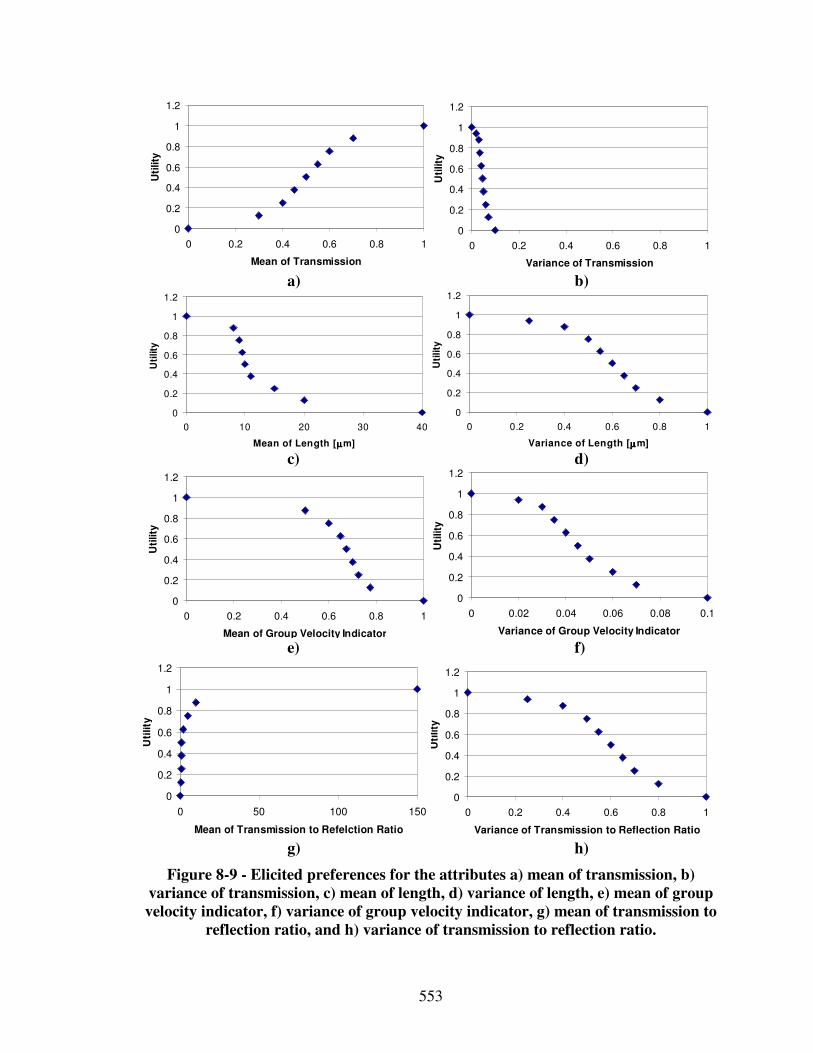
553
0
0.2
0.4
0.6
0.8
1
1.2
0 0.2 0.4 0.6 0.8 1
Mean of Transmission
Uti
lity
0
0.2
0.4
0.6
0.8
1
1.2
0 0.2 0.4 0.6 0.8 1
Variance of Transmission
Uti
lity
a) b)
0
0.2
0.4
0.6
0.8
1
1.2
0 10 20 30 40
Mean of Length [µµµµm]
Uti
lity
0
0.2
0.4
0.6
0.8
1
1.2
0 0.2 0.4 0.6 0.8 1
Variance of Length [µµµµm]U
tility
c) d)
0
0.2
0.4
0.6
0.8
1
1.2
0 0.2 0.4 0.6 0.8 1
Mean of Group Velocity Indicator
Uti
lity
0
0.2
0.4
0.6
0.8
1
1.2
0 0.02 0.04 0.06 0.08 0.1
Variance of Group Velocity Indicator
Uti
lity
e) f)
0
0.2
0.4
0.6
0.8
1
1.2
0 50 100 150
Mean of Transmission to Refelction Ratio
Uti
lity
0
0.2
0.4
0.6
0.8
1
1.2
0 0.2 0.4 0.6 0.8 1
Variance of Transmission to Reflection Ratio
Uti
lity
g) h)
Figure 8-9 - Elicited preferences for the attributes a) mean of transmission, b)
variance of transmission, c) mean of length, d) variance of length, e) mean of group
velocity indicator, f) variance of group velocity indicator, g) mean of transmission to
reflection ratio, and h) variance of transmission to reflection ratio.
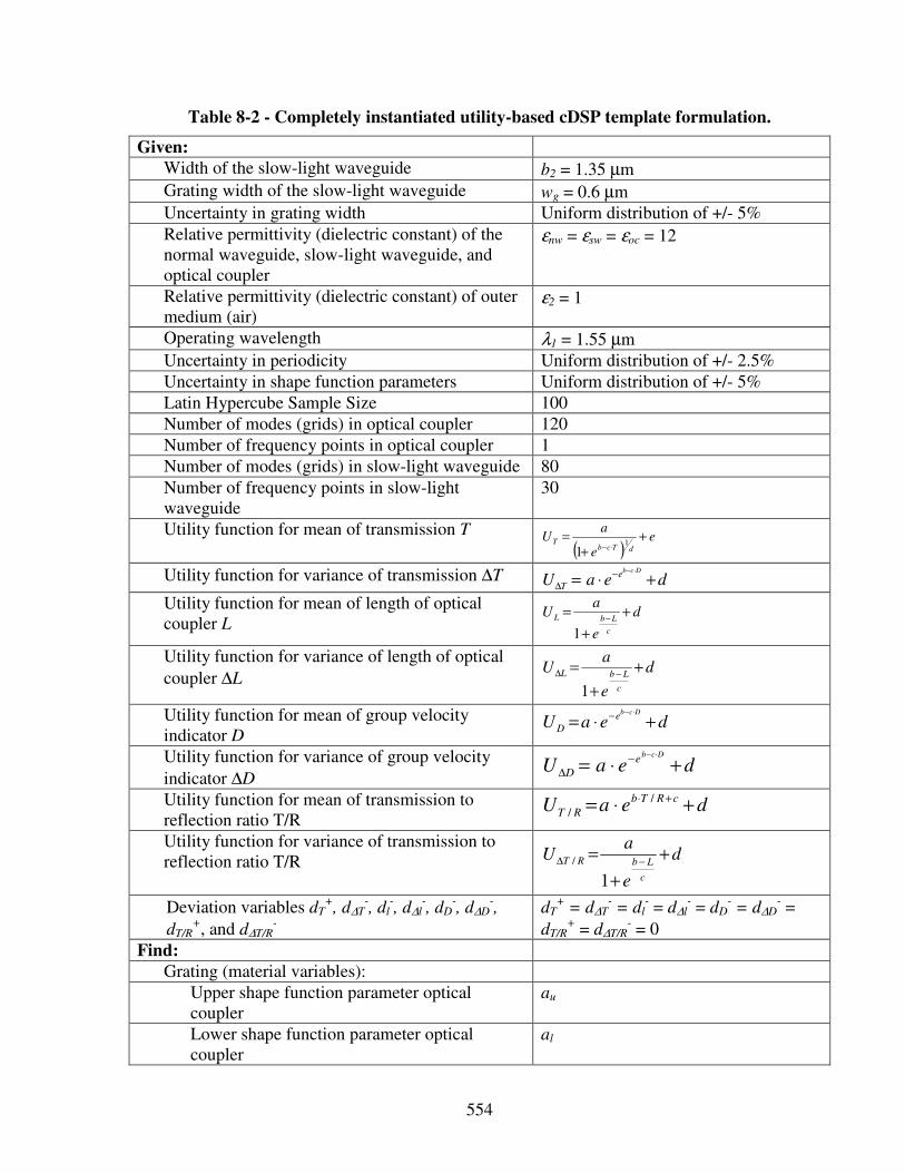
554
Table 8-2 - Completely instantiated utility-based cDSP template formulation.
Given:
Width of the slow-light waveguide b2 = 1.35 µm
Grating width of the slow-light waveguide wg = 0.6 µm Uncertainty in grating width Uniform distribution of +/- 5%
Relative permittivity (dielectric constant) of the normal waveguide, slow-light waveguide, and optical coupler
εnw = εsw = εoc = 12
Relative permittivity (dielectric constant) of outer medium (air)
ε2 = 1
Operating wavelength λ1 = 1.55 µm
Uncertainty in periodicity Uniform distribution of +/- 2.5%
Uncertainty in shape function parameters Uniform distribution of +/- 5%
Latin Hypercube Sample Size 100
Number of modes (grids) in optical coupler 120
Number of frequency points in optical coupler 1
Number of modes (grids) in slow-light waveguide 80
Number of frequency points in slow-light waveguide
30
Utility function for mean of transmission T
( )e
e
aU
dTcbT +
+=
⋅−1
1
Utility function for variance of transmission ∆T deaUDcbe
T +⋅=⋅−−
∆
Utility function for mean of length of optical coupler L
d
e
aU
c
LbL+
+
=−
1
Utility function for variance of length of optical
coupler ∆L d
e
aU
c
LbL +
+
=−∆
1
Utility function for mean of group velocity indicator D
deaUDcb
e
D +⋅=⋅−−
Utility function for variance of group velocity
indicator ∆D deaU
Dcbe
D +⋅=⋅−−
∆
Utility function for mean of transmission to reflection ratio T/R
deaUcRTb
RT +⋅= +⋅ /
/
Utility function for variance of transmission to reflection ratio T/R d
e
aU
c
LbRT +
+
=−∆
1
/
Deviation variables dT+, d∆T
-, dl
-, d∆l
-, dD
-, d∆D
-,
dT/R+, and d∆T/R
-
dT+ = d∆T
- = dl
- = d∆l
- = dD
- = d∆D
- =
dT/R+ = d∆T/R
- = 0
Find:
Grating (material variables):
Upper shape function parameter optical coupler
au
Lower shape function parameter optical coupler
al
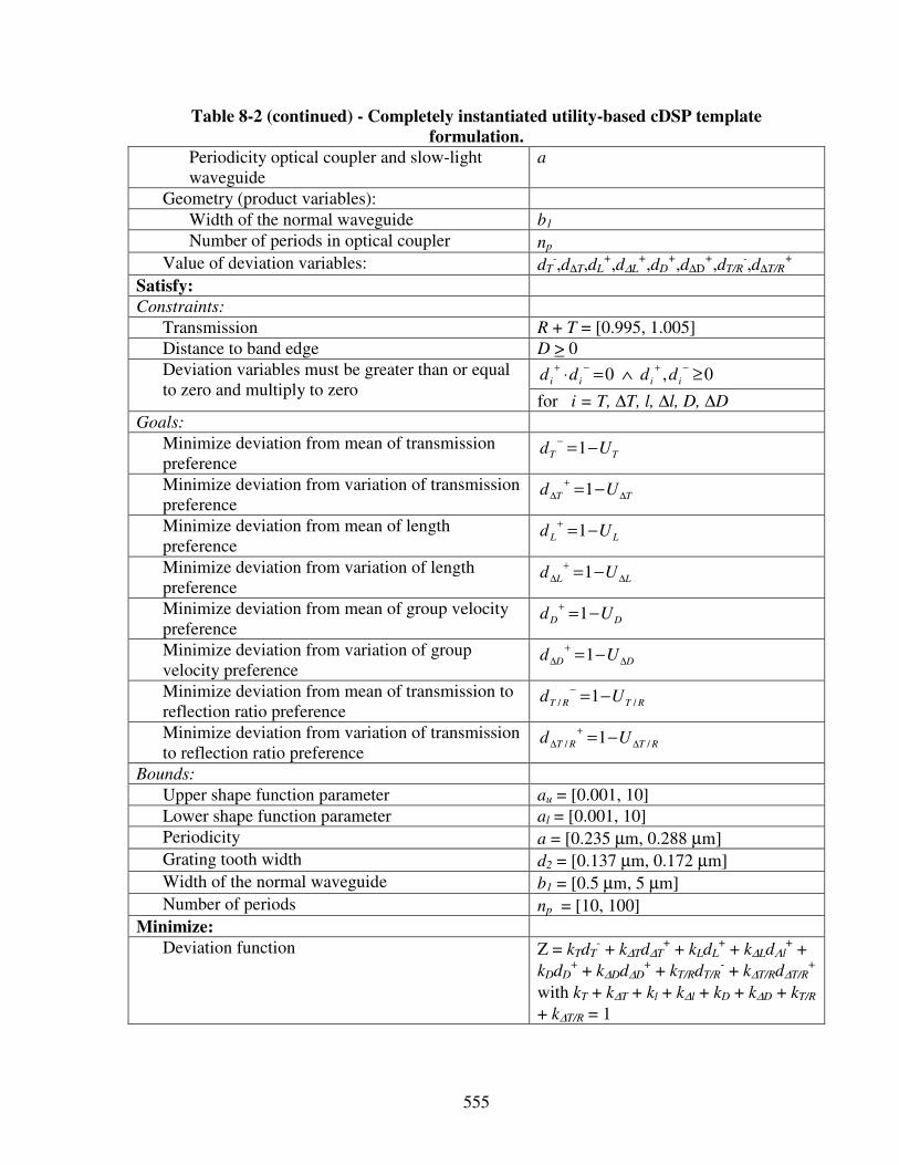
555
Table 8-2 (continued) - Completely instantiated utility-based cDSP template
formulation.
Periodicity optical coupler and slow-light waveguide
a
Geometry (product variables):
Width of the normal waveguide b1
Number of periods in optical coupler np Value of deviation variables: dT
-,d∆T,dL+,d∆L
+,dD+,d∆D
+,dT/R-,d∆T/R
+
Satisfy:
Constraints:
Transmission R + T = [0.995, 1.005]
Distance to band edge D > 0
0,0 ≥∧=⋅−+−+
iiii dddd Deviation variables must be greater than or equal to zero and multiply to zero
for i = T, ∆T, l, ∆l, D, ∆D
Goals:
Minimize deviation from mean of transmission preference
TT Ud −=−
1
Minimize deviation from variation of transmission preference
TT Ud ∆
+
∆ −=1
Minimize deviation from mean of length preference
LL Ud −=+
1
Minimize deviation from variation of length preference
LL Ud ∆
+
∆ −=1
Minimize deviation from mean of group velocity preference
DD Ud −=+
1
Minimize deviation from variation of group velocity preference
DD Ud ∆
+
∆ −=1
Minimize deviation from mean of transmission to reflection ratio preference
RTRT Ud // 1−=−
Minimize deviation from variation of transmission to reflection ratio preference
RTRT Ud // 1 ∆
+
∆ −=
Bounds:
Upper shape function parameter au = [0.001, 10]
Lower shape function parameter al = [0.001, 10]
Periodicity a = [0.235 µm, 0.288 µm]
Grating tooth width d2 = [0.137 µm, 0.172 µm] Width of the normal waveguide b1 = [0.5 µm, 5 µm]
Number of periods np = [10, 100]
Minimize:
Deviation function Z = kTdT- + k∆Td∆T
+ + kLdL+ + k∆LdΛl
+ +
kDdD+ + k∆Dd∆D
+ + kT/RdT/R- + k∆T/Rd∆T/R
+
with kT + k∆T + kl + k∆l + kD + k∆D + kT/R
+ k∆T/R = 1
556
The utility-based cDSP template formulation specified in Table 8-2 is instantiated in
ModelCenter. However, it is important to note that changing the utility function will have
effect on the specific decisions (values of design variables and Process Performance
Indicators) made using the method. However, it does not affect the steps followed in the
method. Even by changing the shape of the preferences in the utility-based cDSP
template formulation, the conclusions about the applicability of the method and the
metrics derived from the method remain the same.
8.3.2 Step B: Select Least Complex Initial Design-Process Alternative
Computing the transmission in arbitrary structures requires an expensive solution of
the complete Maxwell equations. However, various simplified approaches could
potentially be used. But, most of them can’t be extended to the photonic crystal
waveguide structures investigated in this research. For example, effective index models
are based on an uniform medium assumption allowing the consideration of only a single
Bloch mode, that represents a solution to the Helmholtz equation, for the entire structure.
Also, in continuous coupled mode theory, only scattering between propagating Bloch
modes is considered but scattering to evanescent Bloch modes is neglected. It is a
feasible modeling technique only for smaller structures operating away from the bandgap
and where coupling occurs only to first few propagating Bloch modes.
In the photonic crystal waveguide structures investigated in this research however,
one has to deal with more than 100 Bloch modes. Therefore, a design-process based on a
557
vectorial Fourier modal approach that considers scattering between a large number of
Bloch modes is used as the least complex initial design-process alternative to predict
performance, i.e., transmission and group velocity of light in double-grated photonic
crystal waveguide structures. This analysis model is based on the work of V.
Krishnamurthy and Dr. B. Klein from the Computational Electronics Group at the
Georgia Institute of Technology. It has been validated and is relatively computationally
efficient (simulation times on the order of minutes). Therefore, it is accepted as valid and
feasible, and used to instantiate as the initial design-process within the bounds defined in
the cDSP formulation.
The least complex initial design-process alternative is based on direct usage of a
Fourier operator in the Helmholtz equation to enable fast matrix-free processing and
handling of arbitrary dielectric profiles. However, this approach is a modal expansion
method based on discretizing the dielectric structure in the form of 1D/2D in-plane slices
along an out-of-plane direction, then calculating in-plane vectorial 1D/2D modes in each
slice and using them as basis modes to carry out mode-matching analysis along the out-
of-plane direction using scattering or transfer matrix analysis to calculate all modal
expansion coefficients. The expansion coefficients and the vectorial modes are then used
to calculate field distribution throughout the device.
Currently slice modes are calculated by
i) numerically solving analytically derived dispersion relations in each layer, which
restricts the applicability of the method to complicated structures like photonic
crystal defect based lasers, or
558
ii) using the plane wave basis to extend the applicability of the modal expansion
approach to more complicated wavelength scale devices, which however is
limited for small multi-layered defect structures because for large defect
structures the non-sparse matrix grows to such a large size that modal expansion
based real space approaches would be more versatile.
Therefore, in this work, the Fourier operator is used in the vectorial Helmholtz’s equation
for the calculation of layer modes. The resulting more efficient mode-matching theory
based on planewave expansion and scattering matrices as used in this work is called
reciprocal domain modal expansion method and has been developed and validated by V.
Krishnamurthy and Dr. B. Klein from the Computational Electronics Group at Georgia
Tech. For details about this refined analysis model and its validation, the interested reader
is referred to the literature [342, 343].
A simple way of using the reciprocal domain modal expansion method is by
modeling the aperiodic structure of the tapered double-grated waveguide in terms of
periodic supercell boundary conditions along the lateral direction and periodic boundary
conditions along the length of the waveguide, as illustrated in Figure 8-10. Considering a
supercell, i.e., large periodicity, in lateral direction is based on the assumptions that i) the
periodicity in that direction is so large that it does not have any effect on reflection and ii)
transmission results only along the length of the waveguide.
Considering periodic boundary conditions along the length of the waveguide is based
on the assumptions that the structure is slowly varying and reflections are consequently
small, i.e., a slow-taper assumption. In essence, the tapered waveguide is broken up into
various sections of uniform width. Grating parameters of uniform grated waveguides on
559
the microscale are set to calculate effective continuum optical properties of the overall
composite material on a macroscale. Several effective macroscale properties of uniform
grated waveguides with differing width are then used in the tapered, double-grated
waveguide model to calculate the optical properties of the overall waveguide device.
Treating each section as a non-tapered grated waveguide simplifies calculations.
Consequently, as the grating becomes more gradual and the grated waveguide section
length becomes smaller, this model becomes more accurate. Similarly, as the number of
sections is increased, the structure more resembles a tapered grated waveguide. However,
even this least complex initial design-process is relatively complex, but, the most
computationally efficient model available.
8.3.3 Step C: Determine Decision Point
Concept exploration using partially instantiated compromise DSPs is conducted first
to explore the embodiment design space. This is a necessary activity to refine the fully
instantiated compromise DSPs templates given in Table 8-2. In an environment such as
ModelCenter®, the instantiated computational objects that can be manipulated are the
constraints, variables, parameters, goals, response and analysis computational templates.
During concept exploration using partially instantiated cDSP formulations, response
surfaces throughout the feasible design space are explored. Also, extreme values and
main effects are identified. All results in the following are first investigated for equal goal
weightings in the deviation function.
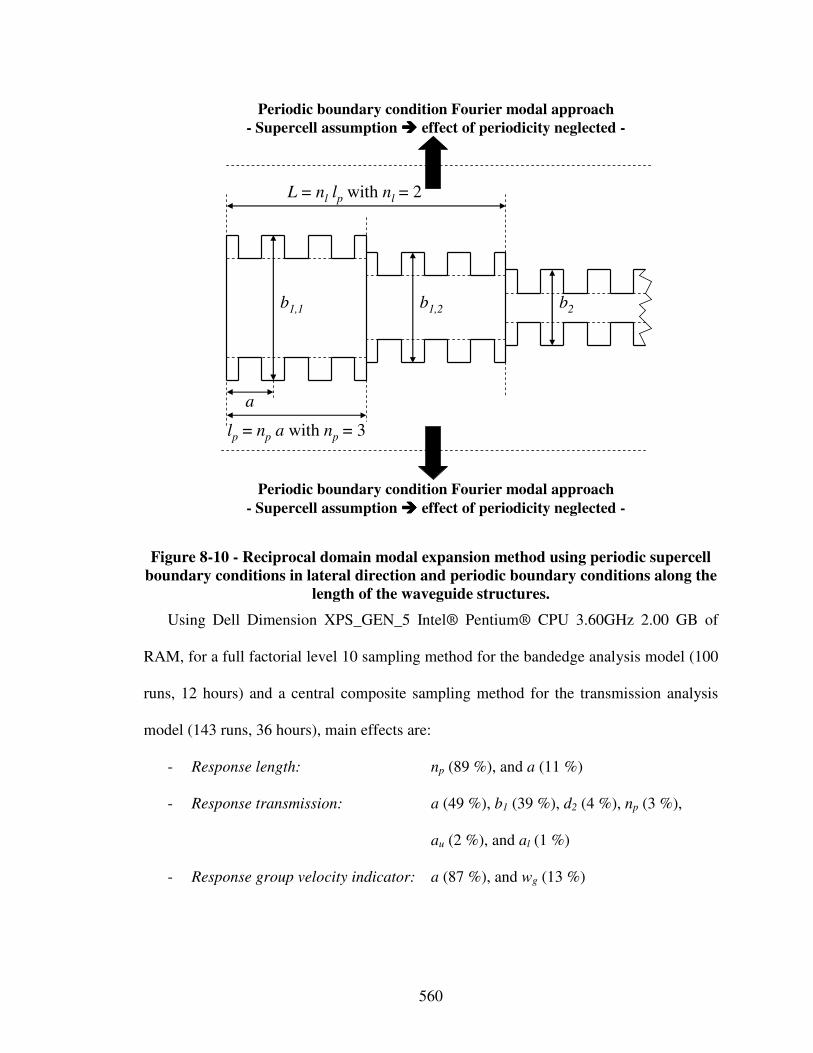
560
Periodic boundary condition Fourier modal approach
- Supercell assumption ���� effect of periodicity neglected -
Periodic boundary condition Fourier modal approach
- Supercell assumption ���� effect of periodicity neglected -
a
lp = np a with np = 3
b1,1 b1,2 b2
L = nl lp with nl = 2
Figure 8-10 - Reciprocal domain modal expansion method using periodic supercell
boundary conditions in lateral direction and periodic boundary conditions along the
length of the waveguide structures.
Using Dell Dimension XPS_GEN_5 Intel® Pentium® CPU 3.60GHz 2.00 GB of
RAM, for a full factorial level 10 sampling method for the bandedge analysis model (100
runs, 12 hours) and a central composite sampling method for the transmission analysis
model (143 runs, 36 hours), main effects are:
- Response length: np (89 %), and a (11 %)
- Response transmission: a (49 %), b1 (39 %), d2 (4 %), np (3 %),
au (2 %), and al (1 %)
- Response group velocity indicator: a (87 %), and wg (13 %)
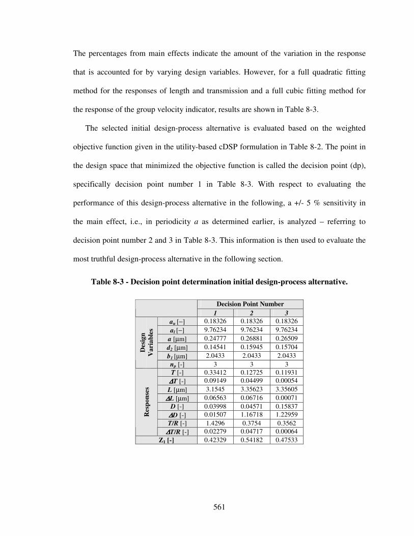
561
The percentages from main effects indicate the amount of the variation in the response
that is accounted for by varying design variables. However, for a full quadratic fitting
method for the responses of length and transmission and a full cubic fitting method for
the response of the group velocity indicator, results are shown in Table 8-3.
The selected initial design-process alternative is evaluated based on the weighted
objective function given in the utility-based cDSP formulation in Table 8-2. The point in
the design space that minimized the objective function is called the decision point (dp),
specifically decision point number 1 in Table 8-3. With respect to evaluating the
performance of this design-process alternative in the following, a +/- 5 % sensitivity in
the main effect, i.e., in periodicity a as determined earlier, is analyzed – referring to
decision point number 2 and 3 in Table 8-3. This information is then used to evaluate the
most truthful design-process alternative in the following section.
Table 8-3 - Decision point determination initial design-process alternative.
Decision Point Number
1 2 3
au [−] 0.18326 0.18326 0.18326
al [−] 9.76234 9.76234 9.76234
a [µm] 0.24777 0.26881 0.26509
d2 [µm] 0.14541 0.15945 0.15704
b1 [µm] 2.0433 2.0433 2.0433
Des
ign
Va
ria
ble
s
np [-] 3 3 3
T [-] 0.33412 0.12725 0.11931
∆∆∆∆T [-] 0.09149 0.04499 0.00054
L [µm] 3.1545 3.35623 3.35605
∆∆∆∆L [µm] 0.06563 0.06716 0.00071
D [-] 0.03998 0.04571 0.15837
∆∆∆∆D [-] 0.01507 1.16718 1.22959
T/R [-] 1.4296 0.3754 0.3562
Res
po
nse
s
∆∆∆∆T/R [-] 0.02279 0.04717 0.00064
Z1 [-] 0.42329 0.54182 0.47533
562
8.3.4 Step D: Select and Evaluate Most Truthful Design-Process Alternative
The classical way of finding an electromagnetic field distribution throughout photonic
crystal structures is by splitting the device into many grids and then solving Maxwell’s
equations in real space using for example finite difference or finite element methods,
based on some form of spatial discretization. Spatial discretization however means that
the structure to be modeled is overlaid with a grid to calculate the electromagnetic field at
each of these grid points. These approaches are very general, robust, and straightforward
with respect to implementation and computation. However, in order to get a decent
accuracy, the grid has to be chosen rather fine, which can lead to long calculation times
and hefty memory requirements. Even though real space approaches are accurate for fine
grids, the problems of physically non-intuitive results, memory inefficiency and slow
performance limit their applicability. On the other hand, reciprocal space approaches or
modal expansion methods like eigenmode expansion [60] and Fourier modal expansion
[356] are known to be faster and provide more physical insight for many problems such
as photonic crystal waveguides.
For the design of a photonic crystal waveguide, frequency and angle of incidence are
usually known. Hence, without significantly reducing prediction accuracy, the problem
can be phrased to find all the spatially scattered propagating and evanescent Bloch
modes. There are various alternate methods to solve Helmholtz’s equation in tapered
grated waveguide structures apart from coupled mode theory [227] or Fourier modal
approach [227, 357] like admittance method [154], method of lines [262], using
analytical modal expansion [60] or eigenmode expansion, multi-pole approach [722], etc.
563
Some of them that are less computationally expensive as potentially addressed when
refining the initial least complex design-process. However, the well-established full-
vectorial Maxwell solver based on eigenmode expansion called CAvity Modeling
Framework (CAMFR) [59] is selected as the most truthful design-process alternative.
CAMFR is a direct numerical solution of Maxwell’s equation – a relatively slow
brute force method not appropriate for rapid design space exploration. CAMFR is based
on the principle of eigenmode expansion to provide an explicit numerical solution of
Maxwell’s equation. Rather than working with a grid, the structure is divided into a
number of layers where the refractive index profile does not change in the z-direction in
each layer. Also, rather than specifying the fields explicitly at a number of grid points, the
fields in each layer are written as a sum of the local eigenmodes of that particular layer.
This leads to a much more compact representation of the field and therefore shorter
computation times. Moreover, contrary to spatial discretization, the calculation time of a
layer is independent of the length of that layer. Also, periodicity or quasi-periodicity is
exploited much more easily.
CAMFR considers lateral absorption boundary conditions and uses scattering matrix
analysis at each point where at cross-section changes continuity conditions of electric and
magnetic fields are ensured. However, it makes no tapering or scattering assumptions, in
contrast to for example coupled-mode theory that is based on the slow-taper or small
scattering assumptions. Hence, it is a “brute-force” method that can be used to solve the
complete Maxwell equations. An arbitrary accuracy can be achieved, given enough
computational time and memory to process a large enough eigenmode basis.
564
This method requires a discrete set of modes. Therefore, CAMFR makes use of
advanced boundary conditions called perfectly matched layers (PMLs). These layers can
be thought of as layers with a real refractive index, but with a complex thickness. This
complex thickness provides for reflectionless absorption of the incident field, regardless
of incidence angle, wavelength or polarization. The use of these advanced boundary
conditions yields accuracy of the model [59]. Since CAMFR imposes the incident-wave
boundary conditions analytically due to its eigenmode basis, even tiny reflection
(transmission) coefficients can be distinguished with high accuracy.
CAMFR is leveraged as the most truthful design-process alternative. It’s
computational expense does not allow for rapid design space exploration. The number of
points at which eigenmodes are evaluated is determined based on the Richardson error
extrapolation. Of course, the use of physical models, prototypes or experiments as the
most truthful design-process alternative would result in a more enhanced design-process
performance evaluation. However, with respect to the focus on the early embodiment and
conceptual design phases and widespread use of CAMFR to validate analysis models for
photonic crystal devices in the electronics domain, the scope of this work is limited to
simulation-based design. Hence, CAMFR is used as the most truthful design-process
alternative.
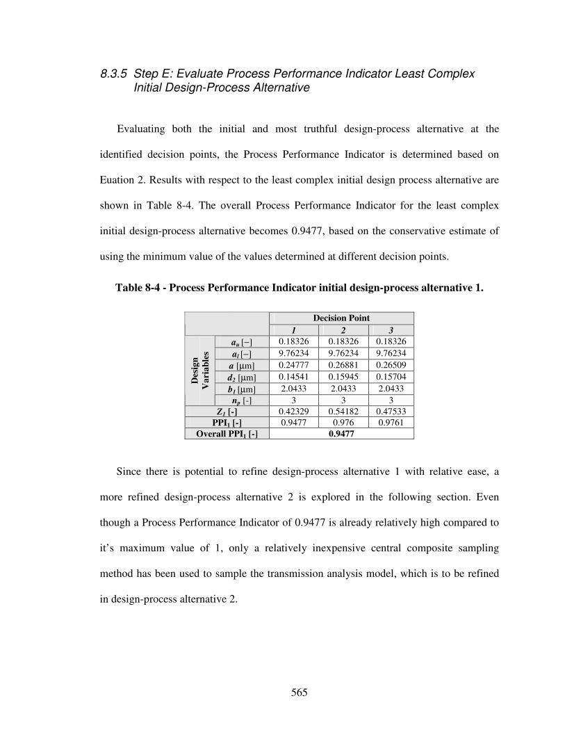
565
8.3.5 Step E: Evaluate Process Performance Indicator Least Complex Initial Design-Process Alternative
Evaluating both the initial and most truthful design-process alternative at the
identified decision points, the Process Performance Indicator is determined based on
Euation 2. Results with respect to the least complex initial design process alternative are
shown in Table 8-4. The overall Process Performance Indicator for the least complex
initial design-process alternative becomes 0.9477, based on the conservative estimate of
using the minimum value of the values determined at different decision points.
Table 8-4 - Process Performance Indicator initial design-process alternative 1.
Decision Point
1 2 3
au [−] 0.18326 0.18326 0.18326
al [−] 9.76234 9.76234 9.76234
a [µm] 0.24777 0.26881 0.26509
d2 [µm] 0.14541 0.15945 0.15704
b1 [µm] 2.0433 2.0433 2.0433
Des
ign
Va
ria
ble
s
np [-] 3 3 3
Z1 [-] 0.42329 0.54182 0.47533
PPI1 [-] 0.9477 0.976 0.9761
Overall PPI1 [-] 0.9477
Since there is potential to refine design-process alternative 1 with relative ease, a
more refined design-process alternative 2 is explored in the following section. Even
though a Process Performance Indicator of 0.9477 is already relatively high compared to
it’s maximum value of 1, only a relatively inexpensive central composite sampling
method has been used to sample the transmission analysis model, which is to be refined
in design-process alternative 2.
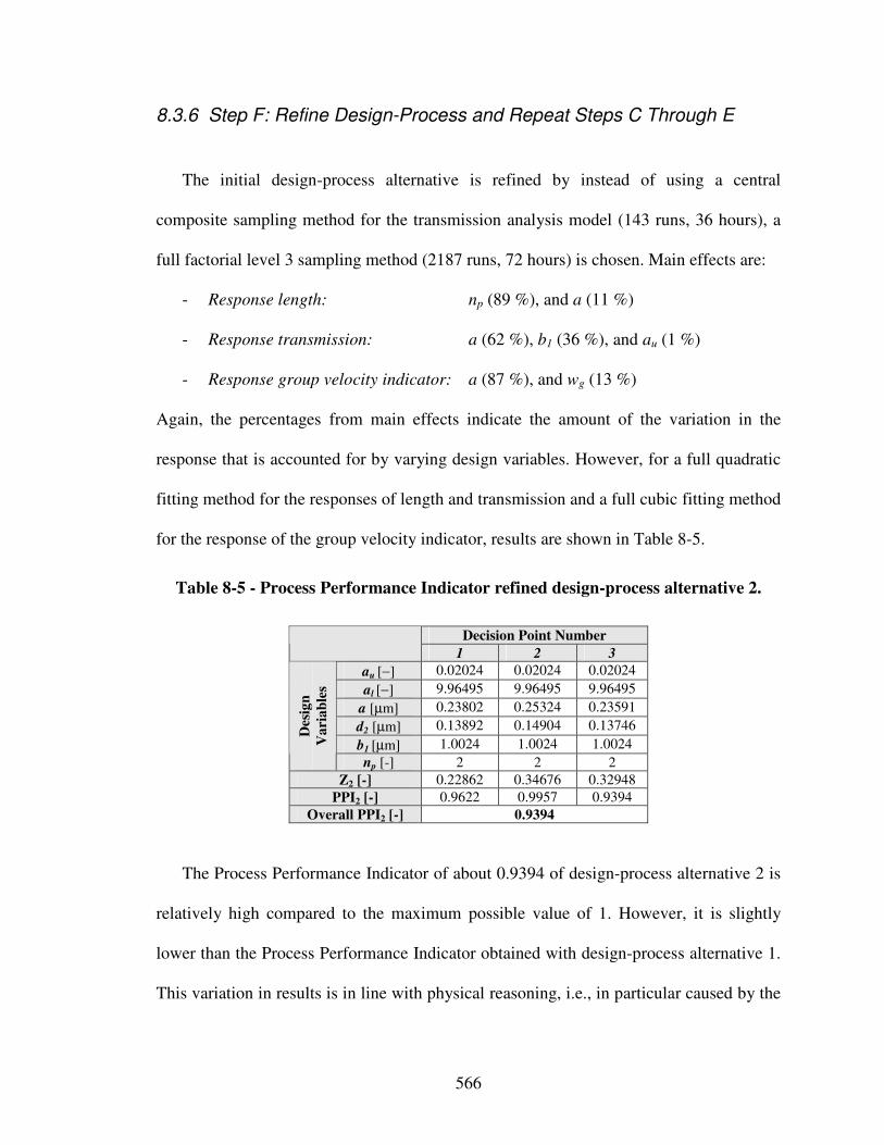
566
8.3.6 Step F: Refine Design-Process and Repeat Steps C Through E
The initial design-process alternative is refined by instead of using a central
composite sampling method for the transmission analysis model (143 runs, 36 hours), a
full factorial level 3 sampling method (2187 runs, 72 hours) is chosen. Main effects are:
- Response length: np (89 %), and a (11 %)
- Response transmission: a (62 %), b1 (36 %), and au (1 %)
- Response group velocity indicator: a (87 %), and wg (13 %)
Again, the percentages from main effects indicate the amount of the variation in the
response that is accounted for by varying design variables. However, for a full quadratic
fitting method for the responses of length and transmission and a full cubic fitting method
for the response of the group velocity indicator, results are shown in Table 8-5.
Table 8-5 - Process Performance Indicator refined design-process alternative 2.
Decision Point Number
1 2 3
au [−] 0.02024 0.02024 0.02024
al [−] 9.96495 9.96495 9.96495
a [µm] 0.23802 0.25324 0.23591
d2 [µm] 0.13892 0.14904 0.13746
b1 [µm] 1.0024 1.0024 1.0024
Des
ign
Va
ria
ble
s
np [-] 2 2 2
Z2 [-] 0.22862 0.34676 0.32948
PPI2 [-] 0.9622 0.9957 0.9394
Overall PPI2 [-] 0.9394
The Process Performance Indicator of about 0.9394 of design-process alternative 2 is
relatively high compared to the maximum possible value of 1. However, it is slightly
lower than the Process Performance Indicator obtained with design-process alternative 1.
This variation in results is in line with physical reasoning, i.e., in particular caused by the
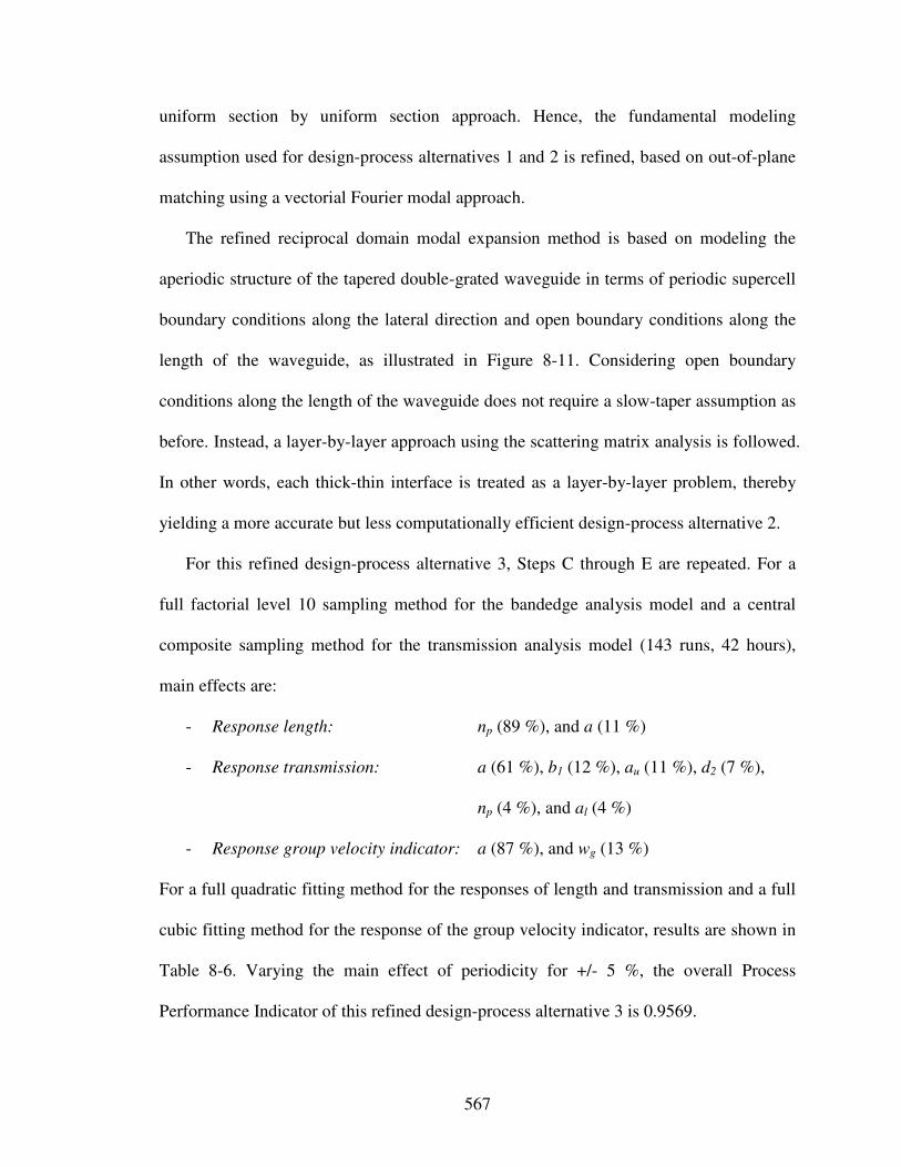
567
uniform section by uniform section approach. Hence, the fundamental modeling
assumption used for design-process alternatives 1 and 2 is refined, based on out-of-plane
matching using a vectorial Fourier modal approach.
The refined reciprocal domain modal expansion method is based on modeling the
aperiodic structure of the tapered double-grated waveguide in terms of periodic supercell
boundary conditions along the lateral direction and open boundary conditions along the
length of the waveguide, as illustrated in Figure 8-11. Considering open boundary
conditions along the length of the waveguide does not require a slow-taper assumption as
before. Instead, a layer-by-layer approach using the scattering matrix analysis is followed.
In other words, each thick-thin interface is treated as a layer-by-layer problem, thereby
yielding a more accurate but less computationally efficient design-process alternative 2.
For this refined design-process alternative 3, Steps C through E are repeated. For a
full factorial level 10 sampling method for the bandedge analysis model and a central
composite sampling method for the transmission analysis model (143 runs, 42 hours),
main effects are:
- Response length: np (89 %), and a (11 %)
- Response transmission: a (61 %), b1 (12 %), au (11 %), d2 (7 %),
np (4 %), and al (4 %)
- Response group velocity indicator: a (87 %), and wg (13 %)
For a full quadratic fitting method for the responses of length and transmission and a full
cubic fitting method for the response of the group velocity indicator, results are shown in
Table 8-6. Varying the main effect of periodicity for +/- 5 %, the overall Process
Performance Indicator of this refined design-process alternative 3 is 0.9569.
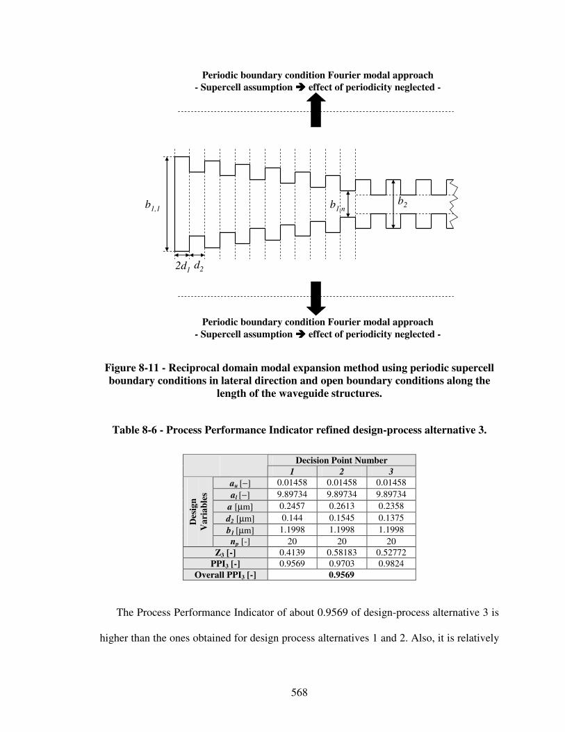
568
Periodic boundary condition Fourier modal approach
- Supercell assumption ���� effect of periodicity neglected -
Periodic boundary condition Fourier modal approach
- Supercell assumption ���� effect of periodicity neglected -
2d1d2
b1,1b2b1,n
Figure 8-11 - Reciprocal domain modal expansion method using periodic supercell
boundary conditions in lateral direction and open boundary conditions along the
length of the waveguide structures.
Table 8-6 - Process Performance Indicator refined design-process alternative 3.
Decision Point Number
1 2 3
au [−] 0.01458 0.01458 0.01458
al [−] 9.89734 9.89734 9.89734
a [µm] 0.2457 0.2613 0.2358
d2 [µm] 0.144 0.1545 0.1375
b1 [µm] 1.1998 1.1998 1.1998
Des
ign
Va
ria
ble
s
np [-] 20 20 20
Z3 [-] 0.4139 0.58183 0.52772
PPI3 [-] 0.9569 0.9703 0.9824
Overall PPI3 [-] 0.9569
The Process Performance Indicator of about 0.9569 of design-process alternative 3 is
higher than the ones obtained for design process alternatives 1 and 2. Also, it is relatively
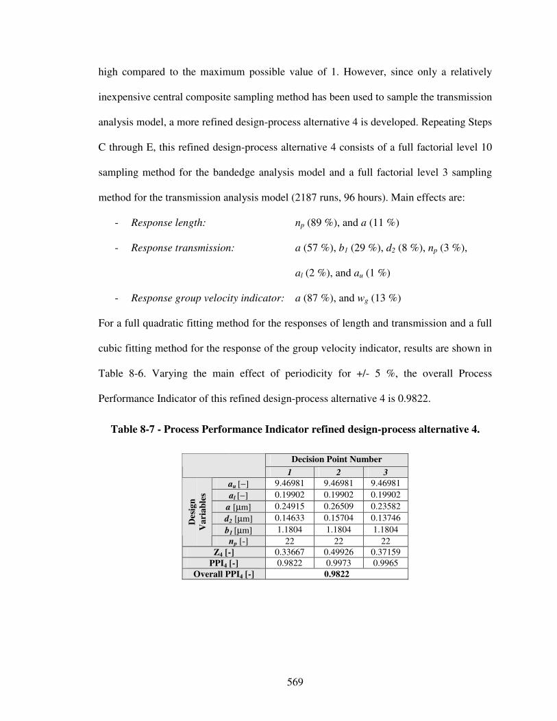
569
high compared to the maximum possible value of 1. However, since only a relatively
inexpensive central composite sampling method has been used to sample the transmission
analysis model, a more refined design-process alternative 4 is developed. Repeating Steps
C through E, this refined design-process alternative 4 consists of a full factorial level 10
sampling method for the bandedge analysis model and a full factorial level 3 sampling
method for the transmission analysis model (2187 runs, 96 hours). Main effects are:
- Response length: np (89 %), and a (11 %)
- Response transmission: a (57 %), b1 (29 %), d2 (8 %), np (3 %),
al (2 %), and au (1 %)
- Response group velocity indicator: a (87 %), and wg (13 %)
For a full quadratic fitting method for the responses of length and transmission and a full
cubic fitting method for the response of the group velocity indicator, results are shown in
Table 8-6. Varying the main effect of periodicity for +/- 5 %, the overall Process
Performance Indicator of this refined design-process alternative 4 is 0.9822.
Table 8-7 - Process Performance Indicator refined design-process alternative 4.
Decision Point Number
1 2 3
au [−] 9.46981 9.46981 9.46981
al [−] 0.19902 0.19902 0.19902
a [µm] 0.24915 0.26509 0.23582
d2 [µm] 0.14633 0.15704 0.13746
b1 [µm] 1.1804 1.1804 1.1804
Des
ign
Va
ria
ble
s
np [-] 22 22 22
Z4 [-] 0.33667 0.49926 0.37159
PPI4 [-] 0.9822 0.9973 0.9965
Overall PPI4 [-] 0.9822
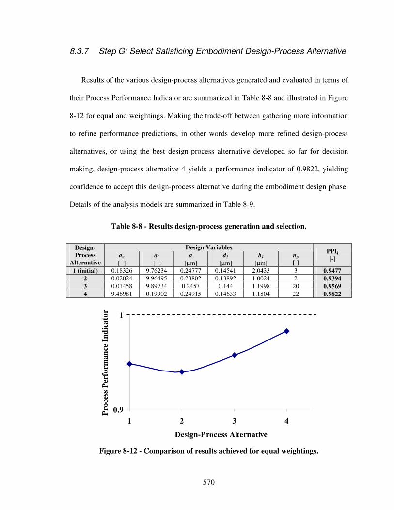
570
8.3.7 Step G: Select Satisficing Embodiment Design-Process Alternative
Results of the various design-process alternatives generated and evaluated in terms of
their Process Performance Indicator are summarized in Table 8-8 and illustrated in Figure
8-12 for equal and weightings. Making the trade-off between gathering more information
to refine performance predictions, in other words develop more refined design-process
alternatives, or using the best design-process alternative developed so far for decision
making, design-process alternative 4 yields a performance indicator of 0.9822, yielding
confidence to accept this design-process alternative during the embodiment design phase.
Details of the analysis models are summarized in Table 8-9.
Table 8-8 - Results design-process generation and selection.
Design Variables Design-
Process
Alternative
au
[−]
al
[−]
a
[µm]
d2
[µm]
b1
[µm]
np [-]
PPIi
[-]
1 (initial) 0.18326 9.76234 0.24777 0.14541 2.0433 3 0.9477
2 0.02024 9.96495 0.23802 0.13892 1.0024 2 0.9394
3 0.01458 9.89734 0.2457 0.144 1.1998 20 0.9569
4 9.46981 0.19902 0.24915 0.14633 1.1804 22 0.9822
0.9
1
1 2 3 4
Design-Process Alternative
Pro
cess
Per
form
an
ce I
nd
ica
tor
Figure 8-12 - Comparison of results achieved for equal weightings.
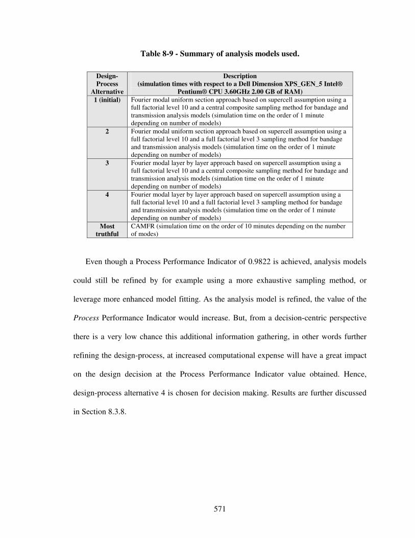
571
Table 8-9 - Summary of analysis models used.
Design-
Process
Alternative
Description
(simulation times with respect to a Dell Dimension XPS_GEN_5 Intel®
Pentium® CPU 3.60GHz 2.00 GB of RAM)
1 (initial) Fourier modal uniform section approach based on supercell assumption using a full factorial level 10 and a central composite sampling method for bandage and transmission analysis models (simulation time on the order of 1 minute depending on number of models)
2 Fourier modal uniform section approach based on supercell assumption using a full factorial level 10 and a full factorial level 3 sampling method for bandage and transmission analysis models (simulation time on the order of 1 minute depending on number of models)
3 Fourier modal layer by layer approach based on supercell assumption using a full factorial level 10 and a central composite sampling method for bandage and transmission analysis models (simulation time on the order of 1 minute depending on number of models)
4 Fourier modal layer by layer approach based on supercell assumption using a full factorial level 10 and a full factorial level 3 sampling method for bandage and transmission analysis models (simulation time on the order of 1 minute depending on number of models)
Most
truthful
CAMFR (simulation time on the order of 10 minutes depending on the number of modes)
Even though a Process Performance Indicator of 0.9822 is achieved, analysis models
could still be refined by for example using a more exhaustive sampling method, or
leverage more enhanced model fitting. As the analysis model is refined, the value of the
Process Performance Indicator would increase. But, from a decision-centric perspective
there is a very low chance this additional information gathering, in other words further
refining the design-process, at increased computational expense will have a great impact
on the design decision at the Process Performance Indicator value obtained. Hence,
design-process alternative 4 is chosen for decision making. Results are further discussed
in Section 8.3.8.
572
8.3.8 Discussion of Results
Based on the results obtained in Section 8.3.1 through 8.3.7, the optical coupler is
designed as a preliminary layout for the scenario of:
1) equal weightings for multiple objectives as specified in Table 8-2, and
2) only considering mean and variance of transmission objective.
Scenario 1 results in a preliminary layout with a periodicity a = 0.24915 µm, grating
tooth width d2 = 0.14633 µm, upper shape parameter au = 9.46981, lower shape
parameter al = 0.19902, width of the normal waveguide b1 = 1.1804, and a number of
periods np = 22. Using the Fourier modal layer by layer approach based on supercell
assumption, results are a transmission coefficient T = 37.96 %, variance in transmission
∆T = 0.00077, an optical coupler length L = 5.48198 µm, variance in optical coupler
length ∆L = 0.00109 µm, group velocity indicator D = 0.03228 with a variance ∆D =
0.00278, and a transmission to reflection ratio T/R = 0.6641 with a variance ∆T/R =
0.00092.
Scenario 2 results in a preliminary layout with a periodicity a = 0.23596 µm, grating
tooth width d2 = 0.13746 µm, upper shape parameter au = 5.4449, lower shape parameter
al = 9.99, width of the normal waveguide b1 = 1.0001, and a number of periods np = 78.
Using the Fourier modal layer by layer approach based on supercell assumption, results
are a transmission coefficient T = 88.45 %, variance in transmission ∆T = 0.00093, an
optical coupler length L = 18.4481 µm, variance in optical coupler length ∆L = 0.00345
µm, group velocity indicator D = 0.084, but with a variance ∆D = 6.16763, and a
transmission to reflection ratio T/R = 10.6566 with a variance ∆T/R = 0.00107.
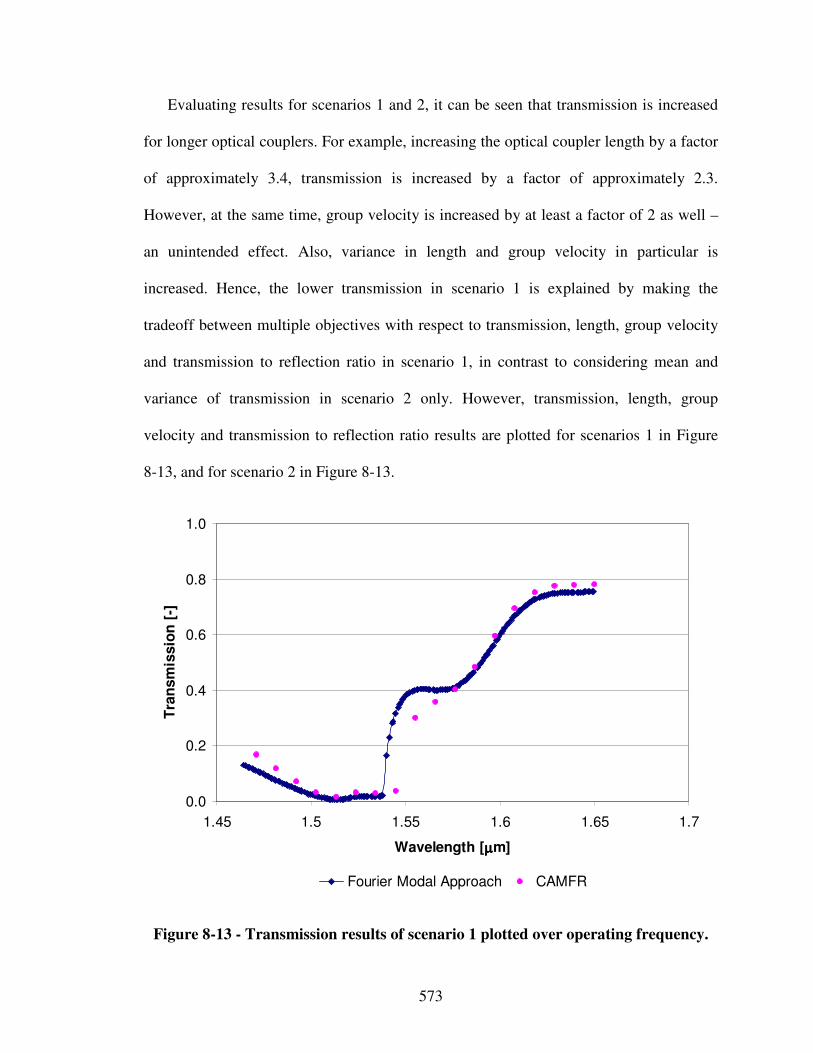
573
Evaluating results for scenarios 1 and 2, it can be seen that transmission is increased
for longer optical couplers. For example, increasing the optical coupler length by a factor
of approximately 3.4, transmission is increased by a factor of approximately 2.3.
However, at the same time, group velocity is increased by at least a factor of 2 as well –
an unintended effect. Also, variance in length and group velocity in particular is
increased. Hence, the lower transmission in scenario 1 is explained by making the
tradeoff between multiple objectives with respect to transmission, length, group velocity
and transmission to reflection ratio in scenario 1, in contrast to considering mean and
variance of transmission in scenario 2 only. However, transmission, length, group
velocity and transmission to reflection ratio results are plotted for scenarios 1 in Figure
8-13, and for scenario 2 in Figure 8-13.
0.0
0.2
0.4
0.6
0.8
1.0
1.45 1.5 1.55 1.6 1.65 1.7
Wavelength [µµµµm]
Tra
nsm
issio
n [
-]
Fourier Modal Approach CAMFR
Figure 8-13 - Transmission results of scenario 1 plotted over operating frequency.
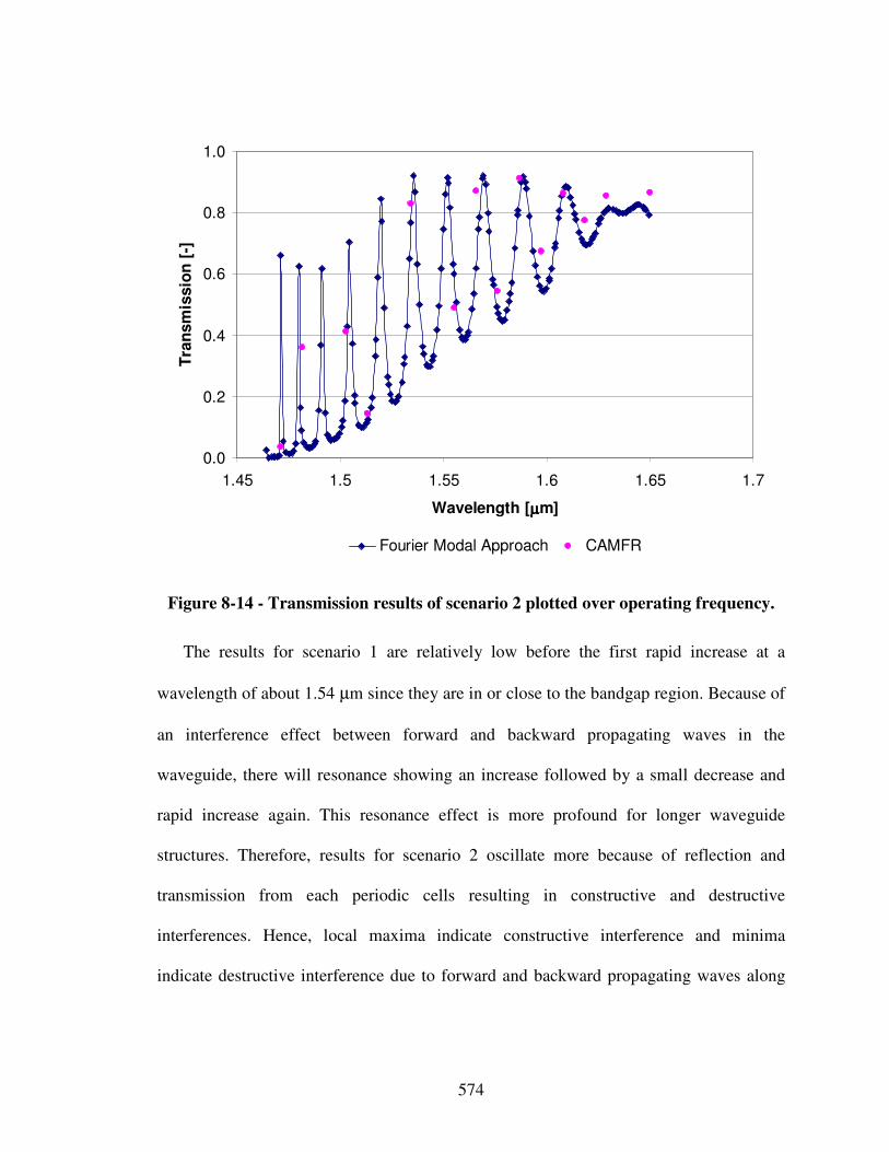
574
0.0
0.2
0.4
0.6
0.8
1.0
1.45 1.5 1.55 1.6 1.65 1.7
Wavelength [µµµµm]
Tra
nsm
issio
n [
-]
Fourier Modal Approach CAMFR
Figure 8-14 - Transmission results of scenario 2 plotted over operating frequency.
The results for scenario 1 are relatively low before the first rapid increase at a
wavelength of about 1.54 µm since they are in or close to the bandgap region. Because of
an interference effect between forward and backward propagating waves in the
waveguide, there will resonance showing an increase followed by a small decrease and
rapid increase again. This resonance effect is more profound for longer waveguide
structures. Therefore, results for scenario 2 oscillate more because of reflection and
transmission from each periodic cells resulting in constructive and destructive
interferences. Hence, local maxima indicate constructive interference and minima
indicate destructive interference due to forward and backward propagating waves along
575
the length of the waveguide. A few points have been obtained using CAMFR to back up
the results obtained with the Fourier Modal Approach.
The preliminary optical coupler and slow-light waveguide layouts obtained are now
to be further explored and detailed during the embodiment and detail design phases
through for example experimental testing and rapid prototyping as well as planning of
realization and value-chain processes depending on the preferred design-processes
followed. Also, another refined reciprocal domain modal expansion method could be
based on modeling the aperiodic structure of the tapered double-grated waveguide in
terms of absorption layer boundary conditions along the lateral direction and open
boundary conditions along the length of the waveguide, as illustrated in Figure 8-15.
This refined design-process alternative, considering open boundary conditions along
the length of the waveguide, would not require a slow-taper assumption as before.
Instead, a layer-by-layer approach using the scattering matrix analysis is followed. In
other words, each thick-thin interface is treated as a layer-by-layer problem, thereby
yielding a more accurate but less computationally efficient design-process alternative
than design-process alternatives 1 and 2. However, also considering absorption layer
boundary conditions along the lateral direction excludes the effect of periodicity in lateral
direction and hence makes the supercell boundary conditions obsolete. Hence, this would
yield a more refined design-process alternative 5 compared to design-process alternatives
3 and 4. However, the Process Performance Indictor of design-process alternative 4 is
already 0.9822, making the development of such a refined design-process alternative
obsolete.
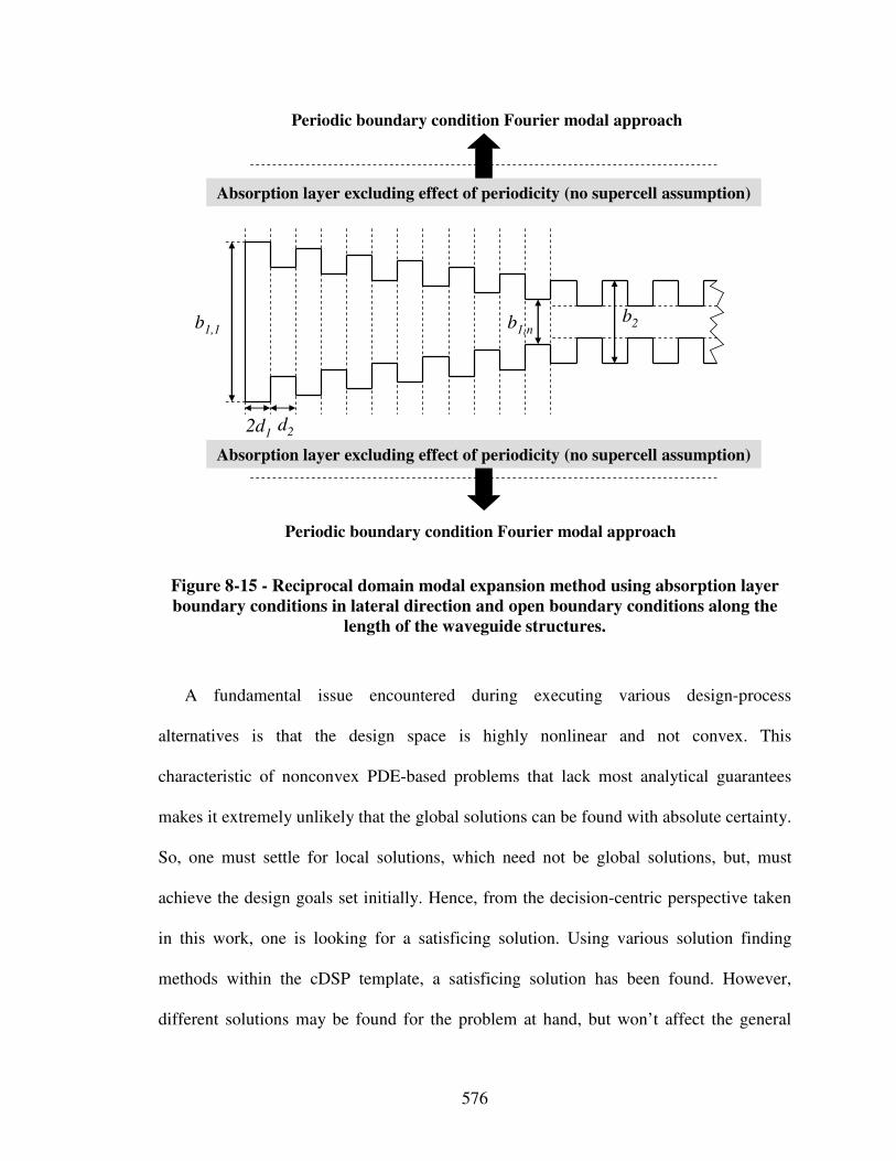
576
2d1d2
Periodic boundary condition Fourier modal approach
Absorption layer excluding effect of periodicity (no supercell assumption)
Absorption layer excluding effect of periodicity (no supercell assumption)
Periodic boundary condition Fourier modal approach
b1,1 b1,nb2
Figure 8-15 - Reciprocal domain modal expansion method using absorption layer
boundary conditions in lateral direction and open boundary conditions along the
length of the waveguide structures.
A fundamental issue encountered during executing various design-process
alternatives is that the design space is highly nonlinear and not convex. This
characteristic of nonconvex PDE-based problems that lack most analytical guarantees
makes it extremely unlikely that the global solutions can be found with absolute certainty.
So, one must settle for local solutions, which need not be global solutions, but, must
achieve the design goals set initially. Hence, from the decision-centric perspective taken
in this work, one is looking for a satisficing solution. Using various solution finding
methods within the cDSP template, a satisficing solution has been found. However,
different solutions may be found for the problem at hand, but won’t affect the general
577
principles and most importantly validation of Research Hypothesis 2 in the context of this
dissertation. However, solutions found should be refined in subsequent design phases
through for example experimental testing and rapid prototyping as well as planning of
realization and value-chain processes depending on the preferred design-processes
followed.
8.4 Verification and Validation
In this Chapter, two aspects of the validation square introduced in Section 1.3 are
addressed – Empirical Structural Validation and Empirical Performance Validation –
illustrated in Figure 8-16 and discussed in the following sections.
8.4.1 Empirical Structural Validation
Empirical structural validation involves accepting the appropriateness of the example
problems used to verify the performance of the method. It is believed that designing
double-grated photonic crystal waveguides in the context of the optoelectronic
communication system example is a reasonably complex multilevel and multiscale design
problem. The design problem allows significant increase in system performance by
exercising systematic concept exploration not only on various system levels down to the
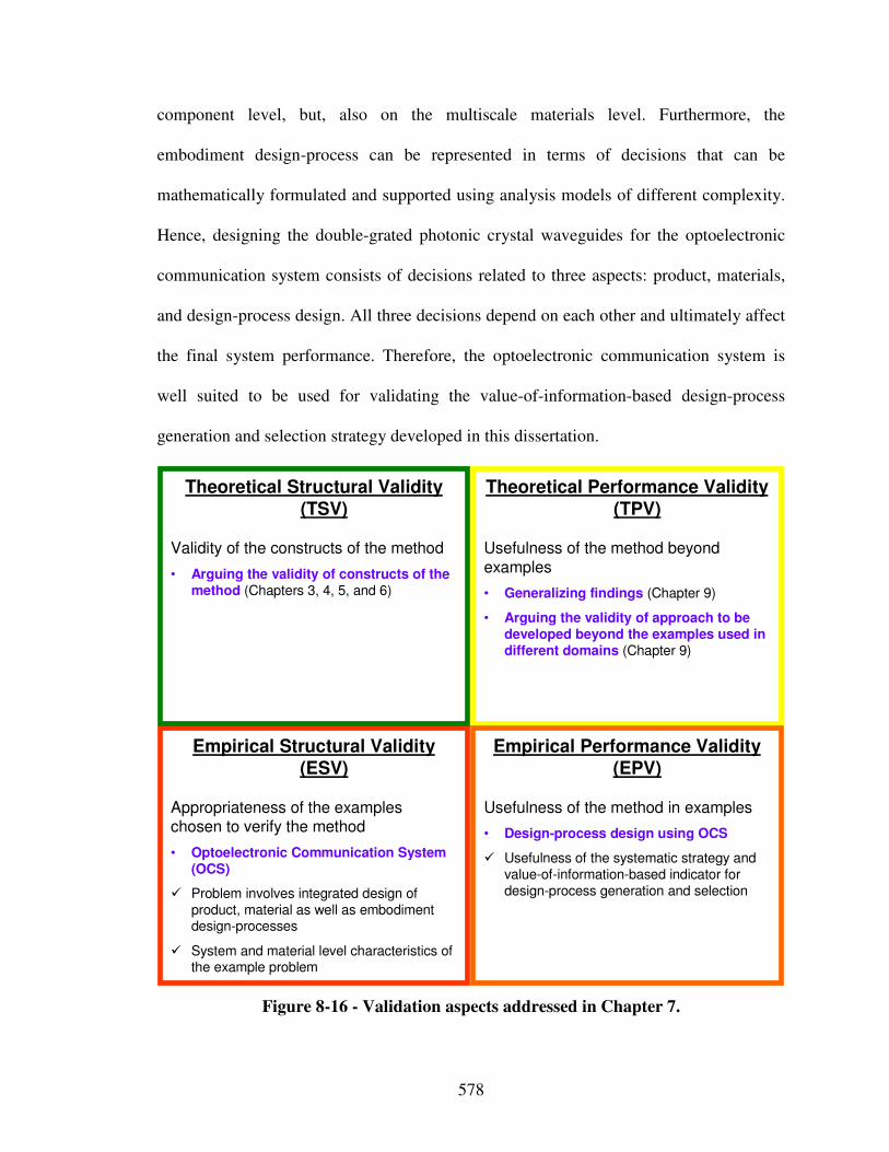
578
component level, but, also on the multiscale materials level. Furthermore, the
embodiment design-process can be represented in terms of decisions that can be
mathematically formulated and supported using analysis models of different complexity.
Hence, designing the double-grated photonic crystal waveguides for the optoelectronic
communication system consists of decisions related to three aspects: product, materials,
and design-process design. All three decisions depend on each other and ultimately affect
the final system performance. Therefore, the optoelectronic communication system is
well suited to be used for validating the value-of-information-based design-process
generation and selection strategy developed in this dissertation.
Empirical Structural Validity (ESV)
Appropriateness of the exampleschosen to verify the method
• Optoelectronic Communication System (OCS)
� Problem involves integrated design of product, material as well as embodiment design-processes
� System and material level characteristics of the example problem
Theoretical Performance Validity (TPV)
Usefulness of the method beyond
examples
• Generalizing findings (Chapter 9)
• Arguing the validity of approach to be developed beyond the examples used in different domains (Chapter 9)
Theoretical Structural Validity (TSV)
Validity of the constructs of the method
• Arguing the validity of constructs of the method (Chapters 3, 4, 5, and 6)
Empirical Performance Validity (EPV)
Usefulness of the method in examples
• Design-process design using OCS
� Usefulness of the systematic strategy and value-of-information-based indicator for design-process generation and selection
Figure 8-16 - Validation aspects addressed in Chapter 7.
579
The most truthful design-process alternative for designing the double-grated
waveguides in the context of the optoelectronic communication system is based on a well
established analysis model called CAMFR. It is considered a benchmark for accuracy for
waveguide applications in particular, but, it’s computational expense makes it’s use for
rapid design-space exploration unfeasible. This motivates the need for selecting a
satisficing design-process alternative such that there is a balance between impact on
decision as well as computational and additional modeling expense. Hence, the design of
double-grated photonic crystal waveguides in the context of the optoelectronic
communication system using the reciprocal domain modal expansion methods is
appropriate for the validation of the value-of-information-based strategy for design-
process generation and selection and the associated Process Performance Indicator.
8.4.2 Empirical Performance Validation
Empirical performance validation consists of accepting the usefulness of the outcome
with respect to the initial purpose and accepting that the achieved usefulness is related to
applying the method. The empirical performance validation of value-of-information-
based strategy to design-process generation and selection as well as the associated
Process Performance Indicator has shown to be effective for increasing efficiency of
design decision making without affecting the quality of decisions, as shown in Section
8.3.
580
Based on the results from photonic crystal waveguide for a next-generation
communication system, it is observed that the selected design-process alternative may
result in similar decisions as the most truthful design-process alternative. In other words,
the selected design-process may result in satisficing decisions. Since a stepwise
refinement of the design-processes is carried out, the most truthful design-process
alternative does not need to be executed. A designer may get the same quality of
decisions efficiently through stepwise refinement.
It is shown that the Process Performance Indicator is valuable for determining a
satisficing design-process alternative while capturing the effect of both uncertainty in
analysis models and a designer’s preferences from a decision-centric perspective. The
results by using the value of information are acceptable and inline with the designer’s
expectations. Hence, it is asserted that empirical performance validity is achieved.
8.5 Role of Chapter 8 in this Dissertation
In this chapter, an integrated product, materials and design-process example – the
design of photonic crystal waveguides for a next-generation optoelectronic
communication system – is illustrated for validation of design systematic design-process
design strategy developed in Chapter 5. The relationship of the validation example
presented in this chapter with other dissertation chapters is presented in Figure 3-11.
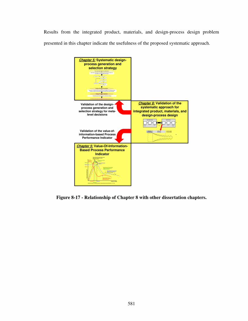
581
Results from the integrated product, materials, and design-process design problem
presented in this chapter indicate the usefulness of the proposed systematic approach.
Chapter 5: Systematic design-
process generation and selection strategy
Chapter 5: Systematic design-process generation and
selection strategy
Chapter 5: Value-Of-Information-Based Process Performance
Indicator
Chapter 8: Validation of the systematic approach for
integrated product, materials, and design-process design
Design Variable
Ex
pe
cte
d O
ve
rall
Pa
yo
ff
Expected payoff usingdesign process alternative 1
(global information)
Expected payoff using refined design process alternative 2
(global information)
Payoff 2
Decision 1 Decision 2
Payoff 1
Process
Performance Indicator 1
Expected payoff using most accurate physical or simulation models
(local information)
Process Performance
Indicator 2
Decisions based on predicted behavior using design process alternatives 1, 2, 3, etc.
Process Performance
Indicator 3
Expected payoff using refined
design process alternative 3(global information)
Payoff 3
Decision 3
Validation of the value-of-information-based Process
Performance Indicator
Validation of the design-process generation and
selection strategy for meta-level decisions
Evaluation of design-process alternatives and additional modeling potential through a value-of-information-based Process Performance Indicator
Systematic generation of design-process alternatives based on
principles from information economics
Design-Process Evaluation
Design-Process Selection
Concept Exploration and Selection
Template-based decision-centric embodiment design
2) Sele ct and Evaluate Simple Initial Design Process Alternative.
4) Evaluate most truthful design process
alternative available.
Step 7: Select satisficing embodiment design process alternative.
1) Formulate Decision U sing Compromise DSP.
3) Determine Decision Point by Solving
cDSP for Maximum Pa yoff.
High Process Per-
for mance Indicator
Low Process
Performance
Indicator
5) Evaluate Process Performance Indicator
Simple Initia l Design-Process Alternative .6) Refine Design-Process and
Repe at Steps 3 Through 5.
…
Signal
(information
input)
Modulator Source
(carrier)
Detector Signal-
processor
Signal
(information
output)
Input- Output-
coupling
TRANSMITTER RECEIVER
a)
b)
NORMAL
WAVEGUIDE
OPTICAL
COUPLER
SLOW-LIGHT
WAVEGUIDE
Figure 8-17 - Relationship of Chapter 8 with other dissertation chapters.
582
Chapter 9 Closure
In this chapter, a summary of this dissertation is given at first. Then, research
questions are revisited as well as verification and validation of the research hypotheses is
addressed in Section 9.2. Achievements and contributions are summarized in Section 9.3,
along with limitations and opportunities for future work in Section 9.4. Finally, the
author’s vision for research in design is addressed in Section 9.5, going beyond the new
interpretation to materials structure-property relations and their classification in design
catalogs facilitating conceptual design of materials integrated with products in a new,
systematic, function-based way, as addressed in this dissertation.
9.1 A Summary of the Dissertation
Problem: Designers are challenged to manage customer, technology, and socio-
economic uncertainty causing dynamic, unquenchable demands on limited resources. In
this context, increased concept flexibility, referring to a designer’s ability to generate
concepts, is crucial. Concept flexibility can be significantly increased through the
integrated design of product and material concepts. Hence, the challenge is to leverage
knowledge of material structure-property relations that significantly affect system
concepts for function-based, systematic design of product and materials concepts in an
integrated fashion.
583
Having selected an integrated product and material system concept, managing
complexity in embodiment design-processes is important. Facing a complex network of
decisions and evolving analysis models a designer needs the flexibility to systematically
generate and evaluate embodiment design-process alternatives through both, simplifying
and refining interactions as well as analysis models. In this work, this flexibility referring
to a designer’s ability to manage complexity in design-process is called design-process
flexibility. Design-process flexibility is particularly important in scenarios when
knowledge of a truthful design-process or its error bounds throughout the whole design
space is not available – crucial for many scenarios especially in integrated product and
materials design.
Approach: In order to address these challenges and respond to the primary research
question of how to increase a designer’s concept and design-process flexibility to
enhance product creation in the conceptual and early embodiment design phases, the
primary hypothesis in this dissertation is embodied as a systematic approach for
integrated product, materials and design-process design to increase a designer’s concept
and design-process flexibility. The systematic approach consists of two components – i) a
function-based, systematic approach to the integrated design of product and material
concepts from a systems perspective, and ii) a systematic strategy to design-process
generation and selection based on a decision-centric perspective and a value-of-
information-based Process Performance Indicator.
Research Question 1 is related to how i) the design of product and material concepts
can be integrated, and ii) conceptual materials be rendered more systematic and domain-
independent. The hypotheses used to answer this research question include functional
584
analysis, abstraction, synthesis, and systematic variation, as well as systematic mappings
of phenomena and associated solution principles classified in design catalogs. The
essence of the function-based systematic approach to integrated product and materials
design is thus to i) increase concept flexibility and ii) enable designers leveraging
underlying phenomena and associated solution principles, materials structure-property
relations on multiple scales in particular, through design catalogs. By operating at the
level of phenomena and associated solution principles, but not at the level of an infinite
number of cases or material artifacts, integrated design of product and material concepts
for revolutionary product creation is facilitated and a particular material/system at any
given time becomes only illustrative of the possibilities, not their determinant.
Research Question 2 is related to managing complexity when configuring networks of
decisions and evolving analysis models constituting embodiment design-processes, i.e.,
the systematic generation, evaluation, and extent of refinement of embodiment design-
processes. The hypothesis used to answer this research question is that a systematic
strategy based on principles from information economics and value-of-information-based
metrics can be used to i) facilitate systematic design-process generation and selection of
“satisficing” embodiment design-process alternatives, and ii) quantify the impact of
refining or simplifying embodiment design-processes with respect to local information.
Local information refers to information at specific points in the design space that can be
readily obtained through for example experimental testing or detailed analysis models
evaluated at specific points in the design space, especially in the context of integrated
product and materials design. Hence, a generally applicable systematic design-process
design strategy from a decision-centric perspective is developed including a value-of-
585
information-based embodiment design-process performance indicator. Thereby, a
designer’s design-process flexibility is increased especially for scenarios in which model
accuracy or error bounds are not known throughout the whole design space – a crucial
scenario in the integrated design of product and material concepts for example.
Validation: The systematic approach is validated using the validation-square
approach that consists of theoretical and empirical validation. Empirical validation of the
framework is carried out using various examples including: i) design of a reactive
material containment system, and ii) design of an optoelectronic communication system.
The function-based, systematic approach to the integrated design of product and material
concepts from a systems perspective is tested using the reactive material containment
system. The systematic strategy to design-process generation and selection from a
decision-centric perspective and a value-of-information-based Process Performance
Indicator is tested using i) the design of multifunctional blast resistant panels for a
reactive material containment system, and ii) the design of photonic crystal waveguides
for a next-generation optoelectronic communication system.
Contribution: The main contribution from this dissertation is the development of a
function-based systematic approach towards the simulation-based integrated design of
products, advanced multifunctional materials, and embodiment design-processes from a
systems perspective, i.e., based on a holistic understanding of the phenomena and
associated solution principles at multiple levels and scales. Hence, foundational to this
dissertation are the following key contributions:
586
i) the new interpretation to materials structure-property relations and their
classification in design catalogs facilitating conceptual design of materials in a
new, systematic, function-based way, and
ii) the systematic strategy to generate and select embodiment design-process
alternatives from a decision-centric perspective and associated value-of-
information-based Process Performance Indicator enabling a designer to generate,
evaluate, and select embodiment design-processes and in a new way.
The details of specific achievements and contributions from this dissertation are
discussed in Section 9.3. First of all, validation of research hypotheses is addressed in
Section 9.2.
9.2 Answering the Research Questions and Validating the Hypotheses
Specific tasks to verify and validate the hypotheses proposed in this research are
summarized in Figure 1-19 and described in the following. A summary of arguments
made throughout the dissertation regarding theoretical structural and empirical validation
for each of the hypotheses are provided in Sections 9.2.1, 9.2.2, and 9.2.3. In Section
9.2.4, focus is on theoretical performance validation, which involves building confidence
in the systematic approach presented for scenarios beyond the specific examples chosen
for validation.
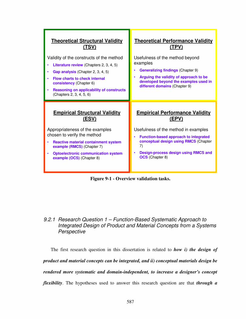
587
(Domain Independent)
Theoretical
Structural
Validity
(Domain Independent)
Theoretical
Performance
Validity
(Domain Specific)
Empirical Structural
Validity
(Domain Specific)
Empirical Performance
Validity
(Domain Independent)
Theoretical
Structural
Validity
(Domain Independent)
Theoretical
Performance
Validity
(Domain Specific)
Empirical Structural
Validity
(Domain Specific)
Empirical Performance
Validity
Empirical Performance Validity (EPV)
Usefulness of the method in examples
• Function-based approach to integrated conceptual design using RMCS (Chapter 7)
• Design-process design using RMCS and OCS (Chapter 8)
Empirical Structural Validity (ESV)
Appropriateness of the examples
chosen to verify the method
• Reactive material containment system example (RMCS) (Chapter 7)
• Optoelectronic communication system example (OCS) (Chapter 8)
Theoretical Performance Validity (TPV)
Usefulness of the method beyond
examples
• Generalizing findings (Chapter 9)
• Arguing the validity of approach to be developed beyond the examples used in different domains (Chapter 9)
Theoretical Structural Validity (TSV)
Validity of the constructs of the method
• Literature review (Chapters 2, 3, 4, 5)
• Gap analysis (Chapter 2, 3, 4, 5)
• Flow charts to check internal consistency (Chapter 6)
• Reasoning on applicability of constructs (Chapters 2, 3, 4, 5, 6)
Figure 9-1 - Overview validation tasks.
9.2.1 Research Question 1 – Function-Based Systematic Approach to Integrated Design of Product and Material Concepts from a Systems Perspective
The first research question in this dissertation is related to how i) the design of
product and material concepts can be integrated, and ii) conceptual materials design be
rendered more systematic and domain-independent, to increase a designer’s concept
flexibility. The hypotheses used to answer this research question are that through a
588
systematic approach from a systems perspective, consisting of a) functional analysis,
abstraction, synthesis, and systematic variation, b) systematic mapping of phenomena,
classified in design catalogs, to multilevel function structures, and c) systematic
mapping of associated solution principles, classified in design catalogs, to phenomena
embodying functional relationships, concept flexibility is increased, the design of
product and material concepts is integrated, and conceptual materials design is
rendered more systematic and domain-independent.
This hypothesis is embodied in i) the systematic approach based on functional
analysis, abstraction, synthesis, and systematic variation developed in Chapter 3, and ii)
the design catalogs developed in Chapter 4 to facilitate systematic mappings of
phenomena and associated solution principles to functional relationships. The essence of
the function-based systematic approach to integrated product and materials design is thus
to i) increase concept flexibility and ii) enable designers leveraging underlying
phenomena and associated solution principles, materials structure-property relations on
multiple scales in particular, through design catalogs. By operating at the level of
phenomena and associated solution principles, but not an infinite number of cases or
material artifacts, integrated design of product and material concepts for revolutionary
product creation is enabled.
Theoretical structural validation refers to accepting the validity of individual
constructs used in the systematic approach and accepting the internal consistency of the
way the constructs are put together. Theoretical structural validation is carried out using a
systematic procedure consisting of a) identifying the method’s scope of application, b)
reviewing the relevant literature and identifying the strengths and limitations of the
589
constructs in the literature, and c) identifying the gaps in existing literature, d)
determining which constructs are leveraged in the systematic approach while exploring
the advantages, disadvantages, and accepted domain of application, and e) checking the
internal consistency of the individual constructs.
Concerning the general methods of functional analysis, abstraction, synthesis, and
systematic variation, it has been argued why these general methods are appropriate for
concept generation for the integrated design of product and material concepts and
materials design in particular. Based on the existing literature, it is shown that these
general methods have been previously used and validated in the context of other
systematic design methods in various domains successfully. However, these general
methods have not been used in a function-based systematic method on the materials level
and for integrated design of product and material concepts as proposed in this work.
From the critical review of the literature in Section 3.2, it is identified that focus of
any function-based systematic method has so far been on mechanical, precision, control,
software, and process engineering. Existing function-based systematic design approaches
depend on the selection of more or less advanced materials from already existing classes
of generic solutions. Furthermore, in general engineering practice, the focus is more on
product-oriented approaches that are prone to solution fixation and intuition when
generating concepts. Hence, the focus in this work is on systematic problem-oriented
conceptual design, based on a functional decomposition and representation of the design-
problem in solution-neutral natural language taking into account in- and output flows.
Operating at the level of phenomena and associated solution principles on various system
levels as well as the multiscale materials level, conceptual design efforts in the product
590
and materials domain are thus integrated and conceptual materials design is rendered
more systematic and domain-independent, thereby increasing a designer’s concept
flexibility compared to a baseline designer.
Concerning the phenomena and associated solution principles design catalogs
developed in Chapter 4, it has been argued why design catalogs are appropriate to
facilitate function-based systematic integrated product and materials design from a
systems perspective. Also, it has been argued that design catalogs are foundational to
developing automated tools to facilitate function-based systematic design, such as for
example case-based reasoning tools. Based on the existing literature, it is shown that
design catalogs have been previously used and validated for facilitating function-based
systematic design in different domains successfully. However, design catalogs for the
materials domain as developed in this work have not yet been addressed. But, in order to
develop wide ranged principal solution alternatives and increase a designer’s concept
flexibility, it is crucial to determine phenomena and associated solution principles on
multiple system levels including the multiscale materials level.
From the critical review of the literature in Section 4.2, it is identified that design
catalogs have been widely used in conceptual design, but, focus has so far been on
developing design catalogs for various types of connections, guides and bearings, power
generation and transmission, kinematics and mechanisms, gearboxes, safety technology,
ergonomics, as well as production processes. Also, physical effects for the specific
domains of mechanical and electrical engineering as well as a few chemical effects have
been classified in the context of systems design. However, so far focus has been on
phenomena and associated solution principles for the product domain from a macro-level
591
perspective, not considering the potential embedded in materials on multiple scales.
During conceptual design, designers are currently used to manipulating materials at the
macro-scale only after having determined a system concept.
In this work, previous efforts are extended to include phenomena and associated
solution principles of relevance to integrated product and materials design. By focusing
on phenomena and associated solution principles – structure-property relations that drive
larger-scale behavior on smaller scales – but not an infinite number of cases or material
artifacts, conceptual product and materials design is integrated and materials design itself
rendered more systematic and domain-independent. In order to facilitate function-based
integrated design of product and material concepts from a systems perspective at the level
of phenomena and associated solution principles, the development of supporting
classification schemes and design catalogs to support a designer in designing material and
product concepts in an integrated fashion.
Stepwise systematic approaches are well established and have been used frequently in
design practice as well as throughout the design literature. One particular example is the
Pahl and Beitz design-process. Although, steps are shown in sequence in Figure 1-3 and
other figures throughout this work, the design-process they represent is often iterative and
undertaken in a concurrent fashion. However, based on the flowchart of the systematic
approach as well as detailed description of tasks needed for each step and the inputs
needed and outputs generated, the internal information flow has been checked to ensure
that sufficient information is available to execute the specific steps. Having critically
evaluated specific steps and the way individual constructs are put together, internal
consistency of the systematic approach is accepted.
592
Due to the logical procedure of literature review, gap analysis, as well as
development and evaluation of a new function-based systematic approach for conceptual
materials design and new design catalogs, the theoretical structural validity of the
construct is accepted. From a theoretical perspective, it is possible to establish the
internal consistency of a method and identify explicitly the favorable and unfavorable
properties of the method for particular application domains. Empirical studies are
required to establish the usefulness and effectiveness of the method.
Empirical structural validation involves accepting the appropriateness of the
example problems used to verify the performance of the method. It is believed that the
reactive material containment system example is a reasonably complex multilevel and
multiscale design problem. Also, the design problem discussed in this chapter allows
significant increase in system performance by exercising systematic conceptual design
not only on various system levels down to the component level, but, also on the
multiscale materials level. Moreover, the problem is suitable because many aspects of
integrated product and materials design can be demonstrated. Hence, the reactive material
containment system example consists of decisions related to product and materials
design. Decisions on product and materials design depend on each other and ultimately
affect the final system performance.
Empirical performance validation consists of accepting the usefulness of the
outcome with respect to the initial purpose and accepting that the achieved usefulness is
related to applying the method. The creation of multilevel function structures as well as
subsequent function-based analysis, abstraction, synthesis, and systematic variation
leveraging design catalogs for phenomena and associated solution principles has shown a
593
significant increase in a designer’s concept flexibility by exercising systematic
conceptual design not only on various system levels down to the component level, but,
also on the multiscale materials level. Also, identifying solution principles on the
multiscale materials level through function-based analysis, abstraction and synthesis,
systematically combining those into concepts and further exploring and refining the most
promising concepts has shown to increase system performance.
The lack of concrete information at these early stages of design is acknowledged.
Hence, not one, but multiple most promising concepts are further explored through
template-based instantiations of compromise Decision Support Problems (cDSPs), before
selection is narrowed down to a single concept. For example, partially instantiated
template-based cDSP formulations (where only the constraints, variables, parameters,
goals, response and analysis entities are instantiated) are used to explore response
surfaces throughout the feasible design space as well as identify extreme values and main
effects. Fully instantiated utility-based cDSP formulations (where driver and objective
entities are instantiated additionally) are then used for multi-objective solution finding to
select a most promising principal solution from the set of feasible concepts identified
earlier.
The main advantage of the function-based systematic approach to the integrated
design of product and material concepts is that a designer’s concept flexibility is
increased – evaluated based on the ease of concept generation as well as increased
concept quantity, variety, novelty, and realizability in the context of the reactive material
containment system example. Also, the systematic approach is problem directed and
594
leads to comprehensive design space expansion and exploration. Modularity,
reconfigurability, transparency, ease of use and interfacing is increased through
functional decompositioning. Also, access to classified and reusable materials domain
expertise is facilitated through attention directing design catalogs and concept selection
charts.
There is a cost associated with generating design catalogs and updating these “living
documents”. Also, systematic concept generation may result in “concept explosion” if
promising concepts are not eliminated early enough. Moreover, function-based
systematic integrated design of product and material concepts requires a more “active
engagement” of designers. But, the ability to design materials is driven by structure-
property relations, not experimental trial and error or infinitely long computational search
through and infinite solution space. Operating at the level of functionality, fundamental
phenomena and associated solution principles, a particular material system is only
illustrative of the possibilities, not their determinant.
9.2.2 Research Question 2 – Value-of-Information-Based Approach to Design-Process Design from a Decision-Centric Perspective
The second research question in this dissertation is related to how can i) a design-
process be generated and selected systematically, and ii) additional modeling potential
and design-process alternatives be evaluated, to increase a designer’s design-process
flexibility and facilitate integrated design of product and material concepts. The
hypotheses used to answer this research question is that through a systematic approach
595
towards embodiment design-process design from a systems perspective, consisting of a)
a systematic strategy to design-process generation and selection from a decision-centric
perspective, and b) a value-of-information-based design-process performance indicator,
design-process flexibility is increased, and additional modeling potential and design-
process alternatives are evaluated to facilitate integrated design of product and
material concepts.
This hypothesis is embodied in a systematic approach to design-process design. It is
based on principles from information economics and value-of-information-based metrics
used to i) facilitate systematic design-process generation and selection of “satisficing”
embodiment design-process alternatives, and ii) quantify the impact of refining or
simplifying embodiment design-processes with respect to local information – information
at specific points in the design space that can be readily obtained through for example
experimental testing or detailed analysis models evaluated at specific points in the design
space, especially in the context of integrated product and materials design. Thereby, a
designer’s design-process flexibility is increased especially for scenarios in which model
accuracy or error bounds are not known throughout the whole design space – a crucial
scenario in the integrated design of product and material concepts for example.
Theoretical structural validation refers to accepting the validity of individual
constructs used in the systematic approach and accepting the internal consistency of the
way the constructs are put together. Theoretical structural validation is carried out using a
systematic procedure consisting of a) identifying the method’s scope of application, b)
reviewing the relevant literature and identifying the strengths and limitations of the
constructs in the literature, and c) identifying the gaps in existing literature, d)
596
determining which constructs are leveraged in the systematic approach while exploring
the advantages, disadvantages, and accepted domain of application, and e) checking the
internal consistency of the individual constructs.
Concerning the value-of-information-based Process Performance Indicator, it has
been argued why value of information is appropriate as a metric for evaluating the
performance of design-processes, i.e., whether a designer needs to determine additional
information. Based on the existing literature, it is shown that value of information has
been previously used for making similar decisions on addition of information for decision
making. The value-of-information-based index developed in this work is an indirect
index, i.e., an index related to direct metrics such as cost and time but more suitable to
the early design phases characterized by more or less incomplete, varying and mostly
qualitative information. Nevertheless, the general value-of-information concept has been
shown to provide a consistent framework from which performance metrics of design-
process alternatives can be quantified.
From the critical review of the literature in Section 5.2, it is identified that the current
metrics for the value of information are not sufficient for many scenarios in integrated
product and materials design. This is primarily due to the assumption that knowledge of a
truthful design-process or its error bounds (either deterministic or probabilistic)
throughout the whole design space is available. Also, existing metrics deal with design-
process simplification and refinement either a) through simplifying and refining
interactions or b) through simplifying and refining analysis models in a complex network
of decisions and analysis models. Furthermore, the assumption of existing approaches is
that designers have the knowledge of a complete network of decisions and analysis

597
models, which is first simplified and then sequentially refined again. Hence, a new value-
of-information-based metric, the Process Performance Indicator, is developed to deal
with strategically refining interactions as well as analysis models starting with the least
complex but valid design-process alternative, while not being dependent on the
knowledge of a truthful design-process or its error bounds (either deterministic or
probabilistic) throughout the whole design space – crucial for many scenarios in
integrated product and materials design.
Based on the flowchart of the systematic approach to design-process design as well as
detailed description of tasks needed for each step and the inputs needed and outputs
generated, the internal information flow has been checked to ensure that sufficient
information is available to execute the specific steps. Having critically evaluated specific
steps and the way individual constructs are put together, internal consistency of the
systematic approach is accepted. Due to the logical procedure of literature review, gap
analysis, as well as development and evaluation of a new strategy and metric, the
theoretical structural validity of the individual constructs is accepted. From a theoretical
perspective, it is possible to establish the internal consistency of a method and identify
explicitly the favorable and unfavorable properties of the method for particular
application domains. Empirical studies are required to establish the usefulness and
effectiveness of the method.
Empirical validation of the value-of-information-based strategy to design-process
generation and selection and the value-of-information-based Process Performance
Indicator to evaluate design-process alternatives is tested using i) the design of
multifunctional blast resistant panels for the reactive material containment system, and ii)
598
the design of double-grated photonic crystal waveguides for the optoelectronic
communication system.
Empirical structural validation involves accepting the appropriateness of the
example problems used to verify the performance of the method. It is believed that
designing multifunctional blast resistant panels for the reactive material containment
system example is a reasonably complex multilevel and multiscale design problem. The
problem is suitable because the embodiment design-process can be represented in terms
of decisions that can be mathematically formulated and supported using analysis models.
Also, only validated analysis models of different complexity have been utilized to
generate and evaluate design-process alternatives. Hence, the reactive material
containment system example consists of decisions related to three aspects: product,
materials, and design-process design. All three decisions depend on each other and
ultimately affect the final system performance.
Also, the most truthful design-process alternative for multifunctional blast resistant
panels in the context of the reactive material containment system is characterized by
significant computational time, making it’s use for design-space exploration unfeasible.
This motivates the need for selecting a satisficing design-process alternative such that
there is a balance between impact on decision as well as computational and additional
modeling expense. Hence, the design of multifunctional blast resistant panels in the
context of the reactive material containment system using analytical and FEM analysis
models is appropriate for the validation of the value-of-information-based strategy for
design-process generation and selection and the associated Process Performance
Indicator.
599
In order to validate the value-of-information-based strategy for design-process
generation and selection and the associated Process Performance Indicator in a different
domain, the design of double-grated photonic crystal waveguides for a next-generation
optoelectronic communication system is considered. It is believed that designing double-
grated photonic crystal waveguides in this context is a reasonably complex multilevel and
multiscale design problem. The design problem allows significant increase in system
performance by exercising systematic concept exploration not only on various system
levels down to the component level, but, also on the multiscale materials level.
Furthermore, the embodiment design-process can be represented in terms of decisions
that can be mathematically formulated and supported using analysis models of different
complexity. Hence, designing the double-grated photonic crystal waveguides for the
optoelectronic communication system consists of decisions related to three aspects:
product, materials, and design-process design. All three decisions depend on each other
and ultimately affect the final system performance. Therefore, the optoelectronic
communication system is well suited to be used for validating the value-of-information-
based design-process generation and selection strategy developed in this dissertation.
The most truthful design-process alternative for designing the double-grated
waveguides in the context of the optoelectronic communication system is based on a well
established analysis model called CAMFR. It is considered a benchmark for accuracy for
waveguide applications in particular, but, it’s computational expense makes it’s use for
rapid design-space exploration unfeasible. This motivates the need for selecting a
satisficing design-process alternative such that there is a balance between impact on
decision as well as computational and additional modeling expense. Hence, the design of
600
double-grated photonic crystal waveguides in the context of the optoelectronic
communication system using the reciprocal domain modal expansion methods is
appropriate for the validation of the value-of-information-based strategy for design-
process generation and selection and the associated Process Performance Indicator.
Empirical performance validation consists of accepting the usefulness of the
outcome with respect to the initial purpose and accepting that the achieved usefulness is
related to applying the method. With respect to the design of i) multifunctional blast
resistant panels for the reactive material containment system, and ii) double-grated
photonic crystal waveguides for a next-generation optoelectronic communication system,
the value-of-information-based strategy for design-process generation and selection as
well as the associated Process Performance Indicator has shown to be effective for
increasing efficiency of design decision making without affecting the quality of
decisions. Based on the results from these examples, it is observed that the selected
design-process alternative may result in similar decisions as the most truthful design-
process alternative. In other words, the selected design-process may result in satisficing
decisions.
Since a stepwise refinement of the design-processes is carried out, the most truthful
design-process alternative does not need to be executed. A designer may get the same
quality of decisions efficiently through stepwise refinement. It is shown that the Process
Performance Indicator is valuable for determining a satisficing design-process alternative
while capturing the effect of both uncertainty in analysis models and a designer’s
preferences from a decision-centric perspective. The results obtained by using the value
601
of information are acceptable and in line with the designer’s expectations. Hence, it is
asserted that empirical performance validity is achieved.
The developed strategy to design-process generation and selection is generally
applicable and well-suited for the integrated design of products and materials. The
advantage of the systematic strategy to design-process generation and selection is that
designers do not need to use the most complex design-process for decision making.
However, more than one refinement step may be required for determining the right level
of design-process refinement. In the worst case, multiple executions of design processes
at increasing levels of refinement may result in significant computational expenses. If this
exceeds the total cost of evaluating the most truthful design-process alternative, this is a
limitation. Hence, there is a tradeoff that calls forth a designer’s judgment based on the
expected benefit from stepwise refinement.
The main advantage of the value-of-information-based Process Performance Indicator
is that it is simple to evaluate and that it quantifies the impact of meta design decisions on
product and material level decisions. Also, it’s evaluation is based only on local
information – information at specific points in the design space that can be readily
obtained through for example experimental testing especially in the context of integrated
product and materials design. With respect to evaluating the Process Performance
Indicator locally, future work might involve advanced strategies to determine at which
points in the design space it is evaluated. Various approaches are presented in this work,
but, additional scenarios should be explored.
602
Confidence in the Process Performance Indicator increases with the number of points
evaluated in the design space. However, if the most truthful design-process alternative
has been evaluated at a sufficient number of points in the design space, a sufficiently
accurate response surface can be generated. Then, this response surface may be used for
design space exploration. Since in the context of integrated product and materials design
the most truthful design-process alternative usually incorporates very expensive to
execute computer or physical analyses, instantiating this design-process alternative at a
sufficient number of points to generate a sufficiently accurate response surface is not
practically feasible since fidelity is sacrificed for computational efficiency.
9.2.3 Primary Research Question – Systematic Approach to the Integrated Design of Products, Materials and Design-Processes
Having discussed theoretical structural, as well as empirical structural and
performance validity in Sections 9.2.1 and 9.2.2, the systematic approach to the
integrated design of products, multifunctional materials, and embodiment design-
processes from a systems perspective is addressed in this section. This overall systematic
approach is developed in this dissertation to answer the primary research question – How
can concept flexibility be increased, and design-process flexibility be increased, to
enhance product creation in the conceptual and early embodiment design phases? The
hypothesis used to answer this question is that through systematic integrated design of
product and material concepts from a systems perspective, and systematic design-
process design leveraging principles from information economics, a systematic
603
approach towards integrated product, advanced multifunctional materials, and
associated embodiment design-process design is developed to increase a designer’s
concept and design-process flexibility.
The overall systematic approach to the integrated design of products, materials and
design-processes consists of two phases: the conceptual and meta design phase. For the
conceptual design phase, the function-based systematic approach to the integrated design
of product and material concepts is developed as the first component of the overall
systematic approach, as described in Section 9.2.1. For the meta design phase, the
systematic value-of-information-based approach to design-process design from a
decision-centric perspective is developed as the second component of the overall
systematic approach, as described in Section 9.2.2.
Integration of both components has shown that the internal structure of the resulting
systematic approach to the integrated design of products, materials, and design-processes
is not incompatible. In fact, integrating both components results in a coherent succession
of information transformations and a coherent overall flow of information. However, the
resulting overall systematic approach is still modular. For example, if a principal solution
has already been specified, the first conceptual design phase can be omitted and
execution of the overall systematic approach is focused on the systematic design of
associated embodiment design-processes, as exemplified in the context of the
optoelectronic communication system.
Stepwise systematic approaches are well established and have been used frequently in
design practice as well as throughout the design literature. In the overall systematic
approach developed in this dissertation, the conceptual design phase involves Steps 1 and
604
2, and the meta-design phase involves Steps 3 and 4, as described in detail in Section 6.2.
During Steps 1 and 2, the function-based systematic approach is executed to design
integrated products and material concepts; during Steps 3 and 4, the systematic approach
is executed to design associated embodiment design-processes. Hence, Steps 1 and 2
focused on concept generation and narrowing concept selection down to a principal
solution, whereas Steps 3 and 4 focused on generating and selecting a satisficing
embodiment design-process for the principal solution identified earlier. However, the
systematic approach is modular in that a designer may skip steps if applicable. Specific
steps only represents operational guidelines for actions.
The use of Decision Support Problems throughout both components of the overall
systematic approach facilitates their integration in a manner that combines advantages of
both components. By using selection DSPs as well as partially and fully instantiated
compromise DSPs to narrow selection of concepts down to a principal solution, it is
possible to explore the conceptual design space comprehensively. Leveraging
compromise DSPs, it is possible generate families of solutions embodying a range of
tradeoff between multiple goals. After the compromise DSP is formulated, weights and
targets can be adjusted to shift emphasis among multiple goals or to modify the aspiration
space (defined by goal targets). Design variable bounds and constraint limits can also be
adjusted to shift the boundaries of the feasible design space. In addition, it is possible to
change the objective function formulation with possible formulations including
Archimedean, preemptive, and utility-based.
It is emphasized that in template-based DSPs, changes can be implemented by
changing values of respective building blocks. Also, as leveraged in the systematic
605
approach to design-processes design, building blocks, such as analysis models, may be
replaced completely. Hence, a designer is able to generate a variety of design-process
alternatives using compromise DSPs. It is important to note that actual details of for
example attribute ratings in selection DSPs or utility functions in utility-based
compromise DSPs are based on a designer’s preferences. Certainly, they affect the final
solution but not the application of the design methods developed in this work.
The systematic approach is intended to facilitate generation of integrated product and
material system concepts as well as the generation and selection of associated
embodiment design-processes. Generally, the systematic approach enables design of
materials and design-processes in the early conceptual phases of design. The overall goal
is to extend a designer’s concept and design-process flexibility. However, specifically,
the systematic approach is intended to extend:
• existing conceptual product design approaches by leveraging the potential
embedded in materials design and providing means for generating and selecting
embodiment design-processes,
• existing materials design approaches by allowing for function-based systematic
conceptual materials design and providing enhanced means for generating and
selecting embodiment design-processes,
• existing design-process design approaches by:
i) providing a systematic strategy for design-process generation and selection
from a decision-centric perspective,
606
ii) a value-of-information-based design-process performance indicator that is
useful in many scenarios and particularly the integrated design of product and
materials, as well as
iii) integrating conceptual and meta design.
Integrating conceptual and meta design extends design-process design approaches in that
a designer not only has the flexibility to generate different design-process alternatives,
but, also has the flexibility to select a different principal solution from the many concepts
generated earlier. Hence, if a satisficing design-process for a specific principal solution
can’t be generated, a designer may leverage the increased concept flexibility gained when
exercising phase 1 of the systematic approach and to readily select a different principal
solution.
Based on the flowchart of the overall systematic approach as well as detailed
description of tasks needed for each step and the inputs needed and outputs generated, the
internal information flow has been checked to ensure that sufficient information is
available to execute the specific steps. Having critically evaluated specific steps and the
way individual constructs are put together, internal consistency of the overall systematic
approach is accepted.
Also, empirical studies have been exercised to establish the usefulness and
effectiveness of the components of the method. As described in Sections 9.2.1 and 9.2.2,
empirical structural and performance validity of both components of the systematic
approach have been accepted. Also, the reactive material containment system example
has successfully been used to test the overall systematic approach as a whole. Hence,
empirical structural and performance validity as well as theoretical structural
607
performance validity of the overall systematic approach is accepted. Theoretical
performance validation is further investigated in the following section.
9.2.4 Theoretical Performance Validation of Hypotheses
As discussed in Section 1.2, theoretical performance validity involves showing that
the design methodology is useful beyond the reactive material containment system and
optoelectronic communication system example problems. This involves i) showing that
the example problem is representative of a general class of problems and ii) strengthening
confidence in the design methodology by generalizing findings.
A fundamental characteristic of the example problems that makes them representative
of a general class of problems is:
• increased concept flexibility (i.e., increased concept performance ranges, concept
functionality, concept realizability, ease of concept generation, concept variety,
concept quantity and concept novelty) as well as increased design-process
flexibility enhance a designer’s decision-making capability.
With respect to the systematic function-based approach presented in this dissertation in
particular, characteristics of the example problems are:
• accurate and sufficient information has been utilized to clarify the task,
• the system under consideration can be divided into a finite number of
subproblems represented as functions,
608
• a subproblem can be considered separately and its relations with other
subproblems temporarily suspended,
• subproblems and their solutions can be presented in a morphological matrix,
• appropriate solution-principles have been identified and the associated technology
exists to satisfy functional relationships,
• a global solution to the design problem can be found as a combination of solutions
to the individual subproblems, and
• a global solution is selected in an unbiased way.
With respect to the systematic design-process generation and selection strategy as well as
value-of-information-based Process Performance Indicator, characteristics of the example
problems are:
• decisions can be formulated mathematically and analysis models are available for
design decision-making,
• designers can express their preference in terms of utility functions,
• design-process alternatives can be generated by refining/simplifying interactions
or refining/simplifying analysis models in a complex network of decisions and
models,
• analysis models constituting design-processes used in this dissertation have been
validated (– hence, the focus in this dissertation is not on validation, but
evaluating the value of design-process alternatives to a designer in a given
problem context from a decision-centric design perspective),
609
• a valid truthful analysis models (such as a detailed simulation-based analysis
models, (rapid) physical prototypes or experiments, test specimen, etc.) is known
and available to the designer,
• design-processes are used to make satisficing decisions from a decision-centric
perspective, i.e., driven by the need to improve a designer’s decision making
capability, not the necessary but more scientific need of validating analysis
models constituting design-processes,
• the appropriateness of a design-process can be strictly interpreted in terms of its
impact to overall payoff,
• analysis models used predict trends accurately, and
• the best solution in the design space occurs at the global maximum of the
expected payoff function.
The example problems selected in this dissertation satisfy the characteristics
described above. Also, results have shown that the systematic approach to integrated
product, materials, and design-process design is useful for the examples chosen for
validation. Generalizing results, it can be seen that the two design example problems
tested the research questions and associated hypotheses presented in this work. It is
shown, that augmentations to the existing body of knowledge can be applied to product,
materials and design-process design.
Particularly, functional analysis, abstraction, synthesis, and systematic variation
facilitated through design catalogs have proven to be suitable for conceptual materials
design and increasing a designer’s concept flexibility, i.e., concept quantity, ease of
concept generation, concept variety, concept novelty, as well as concept functionality and
610
realizability. Also, the value-of-information-based strategy for generating and selection
design-process alternatives from a decision-centric perspective increases speed and ease
of information gathering used for decision making without affecting a designer’s decision
making capability, i.e., quality of decision making.
Based on success in theoretical structural as well as empirical structural and
performance validity and logic, the general usefulness of the method can be inferred by
taking the leap of faith and arguing that the systematic approach is valid for other
problems that satisfy the characteristics and assumptions given above. Hence, the value-
of-information-based Process Performance Indicator is considered suitable for making
meta-level decisions such as evaluating performance of design-process alternatives
especially in the context of integrated product and materials design.
In the following section, achievements and contributions from the research presented
in this dissertation are discussed to support theoretical performance validation.
9.3 Achievements and Contributions
The primary research contribution corresponds to the primary research hypothesis – a
systematic approach to allow for function-based systematic design of material and
product concepts as well as associated embodiment design-process from a systems
perspective in an integrated fashion to enhance a designer’s concept and design-process
611
flexibility. This primary research contribution is explained in greater detail by expanding
it into several secondary research contributions in the following. It is described how
contributions have been shown to support theoretical performance validation. A summary
of research contributions is presented in Section 1.2.5 and Table 9-1.
Table 9-1 - Summary of contributions from the dissertation.
Contributions
Design Methodology – Discussed in Section 9.3.1
A systematic approach to the integrated design of products, advanced multifunctional materials and associated embodiment design-processes is created (Section 6.2)
A systematic approach to integrated conceptual product and materials design through functional analysis, abstraction, synthesis, and systematic variation from a systems perspective (Section 3.3)
Design catalogs classifying phenomena and associated solution principles (structure-property relations) on multiple scales in order to facilitate integrated design of product and material concepts from a systems perspective and in order to make materials design more domain-independent (Chapter 4)
Concept selection charts to visualize concept flexibility and map performance ranges of specific concepts or solution principles as attention-directing tools during conceptual design (Section 3.3.3)
Explicit accounting of meta-design in the context of a designer’s preferences (Chapter 5)
A new value-of-information-based Process Performance Indicator (Section 5.3)
A systematic strategy to generating and selecting design-process alternatives from a decision-centric perspective using the Process Performance Indicator (Section 5.4)
Materials Design – Discussed in Section 9.3.2
A systematic approach to make the conceptual design of advanced multifunctional materials on multiple scales more systematic and domain-independent, hence less ad-hoc and intuitive, through systematic mappings of phenomena and associated solution principles (Section 3.3)
Design catalogs classifying phenomena and associated solution principles (structure-property relations) on multiple scales and concept selection charts in order to facilitate and manage conceptual materials design from a systems perspective (Chapter 4)
Basic structure for conceptual design of materials (such as multifunctional blast resistant panels) associated with the phenomenon of (in)elastic deformation (Section 7.3)
Basic structure for the embodiment robust design of multifunctional blast resistant panels and tapered, double-grated photonic crystal waveguides (Sections 7.6, 8.3)
612
9.3.1 Contributions to Design Methodology
With respect to design methodology, a comprehensive systematic approach is created
for the integrated design of products, advanced multifunctional materials and associated
embodiment design-processes. The systematic approach is based on the foundational
elements of designing material concepts in association with product concepts,
embodiment design-processes in association with integrated product and material
concepts, applying a systems-based approach to materials and meta-design, reliance on
robust solutions as opposed to optimum solutions, and the systematic refinement of
design. The strength of this systematic approach is the consideration of materials and
design-processes related decisions during the design of products. Materials domain
decision are made by integrating the design of product and material concepts, meta-
design domain decisions are made by assessing the performance of design-processes in
terms of a value-of-information-based metric.
The important differentiating features and advantages of this systematic approach are
that it enables designers to i) explicitly account for designing material concepts, and ii)
allow meta-design in the context of a designer’s preferences. Integrated product and
material concepts as well as associated embodiment design-processes are specifically
designed for the problem under consideration and a designer’s preferences. Also, in the
systematic approach, design decisions are made by considering not only the average
system performance, but also the variation in performance due to various sources of
uncertainty.
Also, a systematic approach to integrated conceptual product and materials design
through functional analysis, abstraction, synthesis, and systematic variation from a
613
systems perspective is implemented. In order to facilitate systematic mappings of
phenomena and associated governing solution principles from multiple disciplines to
multilevel function structures and in order to make materials design more domain-
independent, design catalogs classifying phenomena and associated solution principles
(structure-property relations) on multiple materials-specific length scales have been
created. Thereby, today’s existing systematic product design approaches are extended.
Generating non-intuitive system concepts in this way, a designer’s concept flexibility is
significantly increased. Moreover, concept selection charts to visualize concept flexibility
and map performance ranges of specific concepts or solution principles as attention-
directing tools during conceptual design have been used. In the overall context of systems
engineering, the systematic approach presented in this dissertation is an integral to the
first design step of most systems design methodologies, such as the one proposed by
Forsberg and Mooz [212].
As discussed, the performance of design-processes is measured in terms of metrics.
The metric investigated in detail in this dissertation is the value-of-information-based
Process Performance Indicator that is used to quantify the impact of additional
information on a designer’s decision making capability especially in the context of
integrated product and materials design, i.e., especially for scenarios in which model
accuracy or error bounds are not known throughout the whole design space. The metric
quantifies the possible improvement in final design decisions in terms of overall payoff.
Utility theory is recommended as a means for measuring a designer’s overall payoff.
Using utility theory, the metric also quantifies the level of achievement of the design
goals in the presence of uncertainty. Different design-process alternatives are compared
614
by modeling the least complex design-process as the available information and more
refined design-process alternatives as “additional information” available for decision
making. The effect of additional information on decisions is calculated and used as the
criterion to decide whether a design-process alternative is appropriate or not.
The meta-design decisions considered in this work include refinement of evolving
simulation models based on fundamentally different assumptions. In order to support
these design-process related decisions, a systematic strategy for using the value-of-
information-based Process Performance Indicator from a decision-centric perspective is
developed in this dissertation. The method is used to support the tradeoff analysis of
refining design-processes to improve the quality of decisions and the increase in cost of
improving the design-process. The application of this strategy requires characterization of
local information obtained at specific points in the design space. However, the systematic
strategy is not limited to evaluating model replacement but can also be used to evaluate
design-process alternatives obtained otherwise, such as through refining or simplifying
interactions in a complex network of decisions and models, especially for scenarios in
which model accuracy or error bounds are not known throughout the whole design space.
In summary, extensions to the design domain are achieved by extending the
applicability of systematic conceptual design methodologies to the domain of materials
design, thereby increasing a designer’s concept flexibility. Also, the field of design-
process design is extended by developing i) a systematic strategy to generating design-
process alternatives from a decision-centric perspective, and ii) a value-of-information-
based Process Performance Indicator to evaluate additional modeling potential and
615
performance of design-process alternatives, thereby increasing a designer’s design-
process flexibility.
9.3.2 Contributions to Materials Design
In order to develop a systematic approach to the integrated design of product,
advanced multifunctional materials, and associated embodiment design-processes, a
function-based systematic approach to the design of material concepts has been
developed to overcome restrictions to product creation imposed by materials selection.
The function-based systematic approach to the design of material concepts makes the
conceptual design of advanced multifunctional materials on multiple scales more
systematic and domain-independent, hence less ad-hoc and intuitive, through systematic
mappings of phenomena and associated solution principles. Systematic mappings are
facilitated through the development of a function repository, an energy-based design
catalog for phenomena, and a scale-based design catalog for associated solution
principles.
Also, as a result of applying the methods to materials design problems, contributions
are made to the field of materials design. The contribution specific to the field of
materials design is a function-based systematic approach for conceptual materials design
and a systematic strategy for embodiment design of materials with consideration of
design-processes. In this dissertation, the design of multifunctional materials is also
carried out in associated with product, i.e., reactive material containment systems
616
(multifunctional blast resistant panels) or double-grated photonic crystal waveguides. The
concurrent design of product, materials, and design-processes is a contribution to the field
of materials design. Also, the design is carried out by considering robustness to
uncertainty.
Apart from these general contributions in the field of materials design, various
contributions specific to the multiscale materials design problem have resulted from this
dissertation. The research presented in this dissertation is instrumental in the
formalization of integrated product, materials, and design-process design problems as
well as in the implementation of conceptual materials design. In this dissertation,
function-based systematic design of material concepts is exercised for the design of
reactive material containment systems. The design of associated embodiment design-
processes is exercised for i) multifunctional blast resistant panels in the context of
reactive material containment systems and ii) double-grated photonic crystal waveguides
in the context of optoelectronic communication systems. Thereby, the “dual-ownership”
of materials design by electrical and mechanical engineering is addressed.
The results of the preliminary design of materials and products are presented in this
dissertation. This information can be used in the future to perform detail design of the
material-product systems. Also, the results from application of design methods to the
examples in this dissertation can be utilized in the future design of corresponding
products. However, the knowledge of the function-based systematic approach to
materials design and the systematic strategy to design-process generation and selection is
useful for any multiscale materials design problem. For example, the function-based
systematic approach, function repository, or phenomena and associated solution

617
principles design catalogs can be used readily for other design problems. Especially the
design catalog for solution principles associated with the phenomenon (in)elastic
deformation can be readily leveraged for conceptual materials design or for management
not only of blast resistant panels.
Product and material properties of principal solution alternatives obtained through
function-based design of integrated product and material concepts may be inputted to
robust design frameworks, such as the one proposed by Mistree, Allen, Chen, Seepersad
or Choi and coauthors [111, 112, 115, 129, 131, 431, 577, 582], for concept exploration
in the early integrated product and materials embodiment design phases. For example, the
robust design frameworks proposed by Chen and coauthors [111, 112, 115] including
recent extensions that address nuances of materials design in the face of various sources
of uncertainty proposed by Choi and coauthors [129, 131] or topology design of
multiphase microstructures as proposed by Seepersad and coauthors [577, 582], are well-
suited since they address the most common classes of materials and product design
problems. Those robust design frameworks are recommended for exploring the concepts
generated through function-based systematic integrated design of product and material
concepts in this work.
Also, the systematic strategy to design-process generation and selection can be
applied to other simulation models at different scales. This is useful in many materials
design scenarios where various evolving models at different stages of development are
present. The refinement of these models requires either development of models at smaller
scales or exhaustive generation of experimental data. Amount of effort for refinement can
either be reduced or targeted if the systematic strategy is applied to determine the
618
potential for additional modeling and the performance of the current design-process
alternative. This is true in any multiscale materials design scenario, and hence is also a
contribution to the general materials design domain.
As a summary, the research presented in this dissertation provides basic structure for
the design of reactive material containment systems, multifunctional blast resistant panels
in particular, and double-grated photonic crystal waveguides in the context of
optoelectronic communication systems – it can be extended to satisfy the complete
requirements lists for design.
9.3.3 Key Contributions
In summary, based on these contributions a designer now has the following abilities
the baseline designer did not have before:
• designing materials in a systematic fashion during the conceptual design phase
facilitated through design catalogs,
• designing products and materials in a function-based, systematic, integrated
fashion from a systems perspective and mapping performance ranges in concept
selection charts, and
• designing associated embodiment design-processes by systematically generating
design-process alternatives and evaluating their performance and the potential for
additional modeling especially in the context of integrated product and materials
design.
619
Therefore, crucial to this dissertation are the following key contributions:
i) the new interpretation to materials structure-property relations and their
classification in design catalogs facilitating conceptual design of materials in a
new, systematic, function-based way, and
ii) the systematic strategy to generate and select embodiment design-process
alternatives from a decision-centric perspective and associated value-of-
information-based Process Performance Indicator enabling a designer to generate,
evaluate, and select embodiment design-processes and in a new way.
Overall, this dissertation is specifically useful for the early phases of integrated product
and materials design, and many other scenarios in systematic product or materials design.
The systematic approach towards integrated design of products, advanced
multifunctional materials, and associated embodiment design-processes from a systems
perspective is validated using example problems in different domains:
i) the design of reactive material containment systems, and
ii) the design of double-grated photonic crystal waveguides for a next-generation
optoelectronic communication system.
However, potential applications are numerous and compelling, and not limited to the two
addressed in this dissertation. A summary of specific limitations of this work and
opportunities for future work are addressed in the following section. The long-term goals
are addressed in Section 9.5.
620
9.4 Summary of Limitations and Opportunities for Future Work
Even though shortcomings of several state of the art product, material, and design-
process design methodologies are addressed in the proposed systematic approach towards
the integrated design of products, advanced multifunctional materials, and associated
embodiment design-processes, it would of course be impudent to claim full integration of
product, materials and design process design through this research. However, the goal of
this research is to further narrow the existing gap as much as possible and bring the body
of knowledge a step further. A summary of specific limitations of this work and
opportunities for future work are addressed in this section. The long-term goals are
addressed in Section 9.5.
There are many limitations to the breadth and extent of the present body of this work.
However, these limitations offer a host of opportunities for future work. Some of the
possible directions for future work are summarized in Table 9-2, including time frames
for each research activity listed, and discussed throughout this section.
9.4.1 Limitations and Opportunities for Future Work – Function-Based Systematic Conceptual Design of Integrated Product and Material Concepts
The possible directions for future work with respect to function-based systematic
conceptual design, as summarized in Table 9-2, are discussed in the following.

621
Table 9-2 - Opportunities for future work and expected time frames.
Section No. Opportunities for Future Work Expected
Time Frame
Extending phenomena and associated solution principles design catalogs and developing new design catalogs including connectivity and automation
2 – ∞ years
Exploring the use of function-based materials design and design catalogs not only for concept generation, but also concept evaluation, innovation management, and other scenarios
1 – 5 years
Refining modeling and selection tools for the function-based systematic approach to the integrated design of product and material concepts as well as concept flexibility indicators
2 – 10 years
Enhancing conceptual design synthesis techniques and applying conceptual design synthesis to materials design
2 – 5 years
Using design principles including platform design for materials design and investigating material design specific principles
2 – 10 years
9.4.1
Fu
nct
ion
-ba
sed
sy
stem
ati
c co
nce
ptu
al
des
ign
Developing an holistic materials design method including solids and fluids
2 – 10 years
Facilitating design-process synthesis and defining fundamental design-process building blocks
1 – 5 years
Enhancing the value-of-information-based Process Performance Indicator
1 – 5 years
Extending value-of-information-based concept to other domains
2 – 10 years
Using multiple metrics simultaneously for design-process design
2 – 10 years
Investigating more complex networks of decisions and models using value-of-information-based metrics
2 – 10 years
9.4.2
Va
lue-
of-
Info
rma
tio
n-B
ase
d
Str
ate
gy
to
Sy
stem
ati
c D
esig
n-
Pro
cess
Des
ign
Designing open design-processes including design-process platforms and families
2 – 10 years
Reactive material containment system - Multiscale design-processes for blast resistant panels - Modeling of advanced energy dissipation mechanisms - Coupled analysis of fluid structure interface
1 – 5 years
9.4.3
Des
ign
Ex
am
ple
Pro
ble
ms
Optoelectronic communication system - System integration - Robust design techniques - Strategies to manage complexity in a complex network of decisions and models
1 – 5 years
622
Extending phenomena and associated solution principles design catalogs and
developing new design catalogs including automation and integration with existing
design catalogs:
In future work, classifying more (preferably all) solution principles associated with
the identified phenomena in design catalogs will greatly facilitate application of the
function-based systematic approach to the integrated design of material and product
concepts from a systems perspective. This should also include integration with other
existing design catalogs. Application maps as starting points for the development of new
design catalogs are given in Table 9-3. Various representative phenomena are chosen to
illustrate the development of new solution principles design catalogs. However, ideally,
solution principles design catalgos should be developed for all phenomena listed in the
phenomena design catalog shown in Table 4-3. Also, with respect to materials design in
particular, not only design catalogs representing structure – property, but also design
catalogs representing processing – structure and processing – property should be
developed. Also, the most promising principal solution alternatives determined in this
dissertation should be further embodied and evaluated with respect to the given
performance goals through the formulation of more comprehensive decision support
problems. Then, concept selection charts can be refined.
In order to turn the design catalogs and function repository developed in this work
into “living” documents and thereby overcome the limitations listed above in the future, a
web-based Function-based Materials Design (FMD) tool has been developed. Through
the web-based FMD tool, i) the function-based systematic approach to conceptual
materials design is described, and ii) an open environment to edit existing and add new
623
design catalogs for solution-principles associated with certain phenomena is provided.
The web-based FMD tool is developed to provide a tradeoff between a “living” (easy to
change, edit and extend) and “moderating” (easy to control and manage changes and
extensions) effect when editing existing and developing new design catalogs.
Future work might involve either integration of the web-based FMD tool with large-
scale established open environments such as Wikipedia or advanced database and search
algorithm programming using for example open-source SQL databases and Apache web
servers. However, future work in this area should only involves bringing the instantiated
web-based FMD tool in a different form, depending on the targeted user, but, keeping it’s
basic structure. The design catalogs and function repository developed in this dissertation
are based on a systematic representation which is well suited to storing information
content in a computer-based form.
Translating design catalogs and function repositories to an advanced computer-based
form is a future research endeavor. As described in Section 4.6, there are currently many
workable computer-enhanced systems that have been developed to aid a designer in
coping, understanding, and effectively utilizing or even anticipating complex information
sets. Some of the first explorations in this area were called knowledge-based or expert
systems. Expert systems essentially codify best practices into a set of rules that can be
used to search through data and then advise a designer on the historically best responses
to a specific situation. The knowledge is contained in the rules, and the intelligence
belongs to the operator. Fuzzy logic has been added as an additional dimensionality to
some expert systems. Moreover, many other approaches in the hugely complex field of
artificial intelligence have been developed, as reviewed in Section 4.6. However, it is
624
important to note that phenomena and associated solution principles listed in the design
catalogs developed in this work represent “least common denominators” from which
concepts, applications or specific cases can be derived. They are intended to serve as
“root mechanisms” to drive materials design rather than a materials design specific
collection of cases.
As a result, this approach requires a much more active engagement by the designer
than do the typical selection approaches. However, if knowledge of a material/system is
tied only into an account of its properties/specifications and a description of its current
application, then that knowledge may become obsolete along with the material/system
quickly. By operating at the level of phenomena and associated solution principles, a
particular material/system at any given time is only illustrative of the possibilities, not
their determinant. As materials/systems cycle through evolution and obsolescence, the
questions that are raised by their uses as for example smart materials should remain.
As described in Section 4.6, even though design catalogs provide an extensive
classified collection of known and proven solutions for easy retrieval or stimulation, any
classification scheme must be considered as a living document which is to be
continuously updated, extended and maintained to keep up with the ever evolving body
of knowledge. Nevertheless, even a more or less complete classification scheme greatly
facilitates the generation of concepts, even those that were typically not considered
before, and therefore significantly increases the designer’s concept flexibility to
overcome bounds on rationality. Also, it strengthens a designer’s confidence when
selecting the most promising solution principles that nothing essential has been
overlooked.
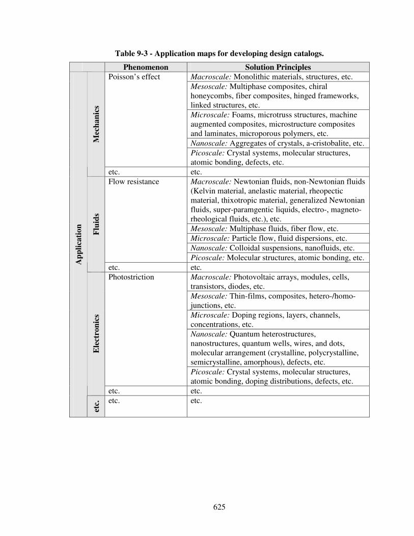
625
Table 9-3 - Application maps for developing design catalogs.
Phenomenon Solution Principles
Macroscale: Monolithic materials, structures, etc.
Mesoscale: Multiphase composites, chiral honeycombs, fiber composites, hinged frameworks, linked structures, etc.
Microscale: Foams, microtruss structures, machine augmented composites, microstructure composites and laminates, microporous polymers, etc.
Nanoscale: Aggregates of crystals, a-cristobalite, etc.
Poisson’s effect
Picoscale: Crystal systems, molecular structures, atomic bonding, defects, etc.
Mec
ha
nic
s
etc. etc.
Macroscale: Newtonian fluids, non-Newtonian fluids (Kelvin material, anelastic material, rheopectic material, thixotropic material, generalized Newtonian fluids, super-paramgentic liquids, electro-, magneto-rheological fluids, etc.), etc.
Mesoscale: Multiphase fluids, fiber flow, etc.
Microscale: Particle flow, fluid dispersions, etc.
Nanoscale: Colloidal suspensions, nanofluids, etc.
Flow resistance
Picoscale: Molecular structures, atomic bonding, etc.
Flu
ids
etc. etc.
Macroscale: Photovoltaic arrays, modules, cells, transistors, diodes, etc.
Mesoscale: Thin-films, composites, hetero-/homo-junctions, etc.
Microscale: Doping regions, layers, channels, concentrations, etc.
Nanoscale: Quantum heterostructures, nanostructures, quantum wells, wires, and dots, molecular arrangement (crystalline, polycrystalline, semicrystalline, amorphous), defects, etc.
Photostriction
Picoscale: Crystal systems, molecular structures, atomic bonding, doping distributions, defects, etc.
Ele
ctro
nic
s
etc. etc.
Ap
pli
cati
on
etc.
etc. etc.
626
Exploring the use of function-based materials design and design catalogs not only for
concept generation, but also concept evaluation, innovation management, and other
scenarios:
Besides facilitating concept generation, systematic function-based materials design
and design catalogs can also be leveraged for analysis, evaluation, innovation
management and other scenaiors. For example, having information on the feasibility of
phenomena and associated solution principles classified in design catalogs, families of
solution principles depending on an unfeasible phenomenon in the given problem context
can be readily excluded from the feasible design space. Also, new, potentially innovative
solution principles to a given problem can be readily classified and evaluated based on
their underlying phenomenon without committing resources to investigating specific
characteristics or properties of particular solution principles.
In summary, leveraging systematic function-based design approaches while operating
at the level of phenomena and associated solution principles greatly facilitates evaluation
and innovation management particularly during conceptual design. The use of function-
based materials design and design catalogs for various scenarios is discussed and
summarized in Table 9-4. However, the application of function-based materials design
and design catalogs is of course not limited to those scenarios. In future work, existing
design catalogs should be continuously extended and updated to provide the best possible
basis not only for the scenrios discussed in Table 9-4.
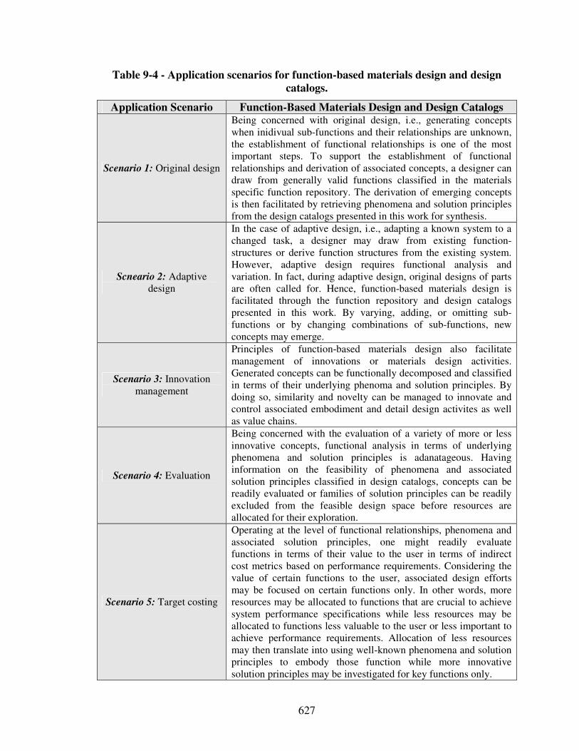
627
Table 9-4 - Application scenarios for function-based materials design and design
catalogs.
Application Scenario Function-Based Materials Design and Design Catalogs
Scenario 1: Original design
Being concerned with original design, i.e., generating concepts when inidivual sub-functions and their relationships are unknown, the establishment of functional relationships is one of the most important steps. To support the establishment of functional relationships and derivation of associated concepts, a designer can draw from generally valid functions classified in the materials specific function repository. The derivation of emerging concepts is then facilitated by retrieving phenomena and solution principles from the design catalogs presented in this work for synthesis.
Scneario 2: Adaptive design
In the case of adaptive design, i.e., adapting a known system to a changed task, a designer may draw from existing function-structures or derive function structures from the existing system. However, adaptive design requires functional analysis and variation. In fact, during adaptive design, original designs of parts are often called for. Hence, function-based materials design is facilitated through the function repository and design catalogs presented in this work. By varying, adding, or omitting sub-functions or by changing combinations of sub-functions, new concepts may emerge.
Scenario 3: Innovation management
Principles of function-based materials design also facilitate management of innovations or materials design activities. Generated concepts can be functionally decomposed and classified in terms of their underlying phenoma and solution principles. By doing so, similarity and novelty can be managed to innovate and control associated embodiment and detail design activites as well as value chains.
Scenario 4: Evaluation
Being concerned with the evaluation of a variety of more or less innovative concepts, functional analysis in terms of underlying phenomena and solution principles is adanatageous. Having information on the feasibility of phenomena and associated solution principles classified in design catalogs, concepts can be readily evaluated or families of solution principles can be readily excluded from the feasible design space before resources are allocated for their exploration.
Scenario 5: Target costing
Operating at the level of functional relationships, phenomena and associated solution principles, one might readily evaluate functions in terms of their value to the user in terms of indirect cost metrics based on performance requirements. Considering the value of certain functions to the user, associated design efforts may be focused on certain functions only. In other words, more resources may be allocated to functions that are crucial to achieve system performance specifications while less resources may be allocated to functions less valuable to the user or less important to achieve performance requirements. Allocation of less resources may then translate into using well-known phenomena and solution principles to embody those function while more innovative solution principles may be investigated for key functions only.
628
Refining modeling and selection tools for the function-based systematic approach to
the integrated design of product and material concepts as well as concept flexibility
indicators:
The design catalogs and function repository presented in this work are developed to
facilitate function-based systematic design of product and material concepts in an
integrated fashion. Specific assumptions and limitations of the function-based systematic
approach to the integrated design of product and material concepts are described in detail
in Section 3.5. Similarly to extensions in design catalogs, future work should involve
extending existing function taxonomies and repositories. This, however, is also a
consequence from applying the function-based systematic approach more widely in
engineering practice. However, applying the function-based systematic approach more
extensively for materials design, future work should also include implementing not only
multilevel function structures, but also time-based function structures or other dynamic
function-based representations to better take into account the effect of time-variant
materials specific phenomena and solution principles, such as diffusion, etc.
Also, concept quantity, ease of concept generation, concept variety and novelty as
well as concept functionality and realizability are used as concept flexibility indicators to
drive systematic concept selection considering multiple criteria. These indicator are not
sufficient for all aspects of importance when evaluating concepts with respect to a
product’s life-cycle – starting from the product’s proposal and performance requirements,
spanning it’s design, realization, use, and evolution, recycling or disposal. But, these
indicators are appropriate to evaluate the information available at these early stages of
design. If for example a product’s embodiment design is not known, cost estimations are
629
less a matter of rigorous analysis and hence of little use. However, indicators and metrics
to evaluate concepts and their level of satisfaction with respect to performance
requirements should be the focus in future work.
Also, integrating function-based systematic design with set-based concept modeling
tools acknowledging the inherent lack of detailed information in the early phases of
design is crucial. For example, due to the ill-structured nature of conceptual design,
objectives and constraints are not clearly understood in the early stages of design. Also,
conceptual design involves different abstract levels of thinking including mere function
structures or rough sketches. Hence, capturing concepts at different abstract levels is
required during modeling. Furthermore, if available, simulation models are evolving and
far from being complete. Hence, formal and informal decision-making must be
accommodated in solution finding and selection methods.
In future work, selection methods should also be advanced to better address
multiscale or hierarchical problems in the context of integrated product and materials
design or in the context of designing complex engineered systems in general. To support
a human decision maker in processing both quantitative and qualitative information on
multiple levels and scales, template-based systematic selection methods for a distributed,
team-based environment should be developed. Due to the inherent lack of knowledge in
the conceptual and early embodiment stages of design, these methods must both capture
“objective” quantitative information and “subjective” experience-based knowledge of the
human decision-maker in a group setting.
Also, in order to better evaluate generated concepts, concept representation tools
should be extended. So far, the focus has been on intuitive geometry modeling tools for
630
conceptual design, such as sketching systems [375, 519, 763], vague discrete modeling
[273], rough sketches, flow diagrams, text notes, or rapid prototypes and digital clay
among others. Integration of such intuitive geometry modeling tools with function-based
systematic design and retrieving or classifying concepts in different representations is an
area of further research. Also, tools are required to facilitate collaborative decision
making in distributed design environments. This includes distributed functional and
geometric modeling systems. Also required are methods for negotiation during
conceptual design. However, integration of human interactivity must be ensured to
facilitate many creative activities during conceptual design. The computer is meant to
support human decision making, not vice versa.
Enhancing conceptual design synthesis techniques and applying conceptual design
synthesis to materials design:
Another approach to support human decision-making is to leverage computational
synthesis techniques for integrated design of product and material concepts. In essence,
the computer is used to synthesize a wide variety of concepts for a given problem and
allow designers to explore these before developing the most promising ones by, for
example, developing advanced clustering and filtering techniques. Furthermore, the
development of algorithms to constantly search the conceptual design space based on
dynamic demands, to combine functions or solution principles, and to proactively
suggesting concepts to a user presents very promising paradigms in computer aided
design. Automated concept generation (synthesis) and concept exploration (analysis) is
often based on pre-specified search parameters. Facing dynamic demands, such rigid
631
decision support tools must be advanced to allow in-time adaptation. Developing
adaptive concept synthesis and analysis systems that combine human intelligence and
perception with computing efficiency is crucial.
Designing concepts, i.e., principal solution alternatives, in response to dynamic
unpredictable demands requires loosely coupled and decentralized adaptive systems. A
promising approach is to apply agent-based modeling (simulating highly complex
systems as groups of many simple agents, e.g., organisms interacting in ecosystems) and
evolutionary solution finding methods (using the principle of survival of the fittest in
populations of many possible solutions, e.g., organisms evolving in ecosystems).
Leveraging design or solution patterns, emerging complex engineered systems can be
synthesized. In this context, structure-property and processing-structure relations or other
phenomena and associated solution principles (classified in design catalogs as addressed
in this work) can be used as problem-independent solution-patterns to generate solutions
adapting to given problems.
Solution patterns, as for example functions classified in function repositories or
phenomena and associated solution principles classified in design catalogs, can be
characterized as specifying generic relations among abstract design elements. The
relations are generic in that they are independent of any specific design situation. The
elements are abstract in that they do not refer to any specific problem. However, solution
patterns can be leveraged as agents, i.e., collections of autonomous decision-making
entities used to synthesize complex, real-word systems. Then, there is no centralized
control or planning required. Agents are highly distributed in nature and follow a few
simple rules. Hence, agents have only local knowledge and visibility but interactions
632
between these agents result in self organization and subsequently emergent global
behavior and complex engineered systems.
Agent-based modeling is particularly well suited to predicting outcomes of complex,
adaptive systems (nonlinear problem spaces involving many imperfect players such as
humans). Also, it can be used to analyze effects of actions in multiple domains. Many
successful applications have been developed. Campbell and coauthors for example
applied agent based modeling to conceptual product design [88, 90, 91]. In combination
with evolutionary algorithms (such as evolutionary strategies and genetic algorithms),
agent-based modeling is thus a promising synthesis approach also for robust decision-
making (through self-adaptation of the algorithm to match the problem or to respond to
the dynamic, uncertain nature of the problem) and integrated product and material design
(synthesis).
In the context of this dissertation, a promising field for future research is to use
phenomena and associated solution principles (processing – structure – property
relations) classified in design catalogs to first design integrated product and material
concepts and thereby narrow down the almost infinite design space encountered in
integrated product and materials design. Then, in order to search the resulting feasible
design space, i.e., explore the concept obtained, agent-based modeling and evolutionary
algorithms are leveraged to synthesize the material and perhaps overall product using
basic solution patterns classified in design catalogs, i.e., phenomena and associated
solution principles, leveraging computational speed and depth of calculation to reduce
tedious human design efforts. Leveraging solution patterns classified in design catalogs
for synthesis in a multi-agent system involves defining interactions and constraints in
633
terms of simple rules for each agent. However, complex material structures resulting in
overall products can thereby be synthesized at various scales with relative ease avoiding
the need for relatively rigid multiscale model building.
As described in detail in Chapter 4, a complexity profile can then be interpreted in
terms of flexibility. From a design synthesis perspective, functions, phenomena and
associated solution principles are leveraged for concept generation. Hence, the more
complexity, i.e., amount of information, at a designer’s disposal, the higher will be a
designer’s flexibility. A designer then has to focus on the value of information available,
as addressed in Chapter 5. However, from this perspective it becomes clear that growing
complexity through integrated product and materials design suggests more responsibility
for designers.
For example, materials scientists focusing on specific phenomena or solution
principles cannot be expected to anticipate all the consequences of designs at a system
level when interactions are taken into account. Hence, synthesizing functions, phenomena
and associated solution principles is a major responsibility of system designers. System
designers then need to focus on orchestrating the interaction of complex assemblies
where the “structure of matter on both a nano- and macroscale is a result of the interplay
between the requirements of the physical forces operating between the individual parts
and the mathematical requirement of space filling” [610]. In order to do that, future work
should also be focused on enhanced behavioral representations through which adverse
emergent effects can be considered by designers.
As described by Smith, “science, art, and history all share common or analogous
patterns of hierarchical order that are embedded into the structure of the material world as
634
well” [610]. For example, in the materials world the transformation of metals from one
state to another, or the contrasts at one scale that emerge through repetition into
uniformity at a higher level, carry solid metaphorical implications for the human
condition. However, observation and cataloging of phenomena and associated solution
principles as addressed in this work is a fundamental first step. In a next step, phenomena
and solution principles identified can then be used for design synthesis.
Related areas of future research include the use of multilevel and multiscale design
approaches for agent based systems or addressing a hierarchy of agents with different
behavior. This may involve developing a mutli-resolution hierarchy of rules based on
interactions between classified solution patterns, rather than having just simple rules at
the lowest or highest level of detail involving for example quantum field theory. An
overarching research question would be how to combine agent-based modeling and
evolutionary algorithms with traditional top-down design from a systems perspective.
Similarly, how can such an approach based on basic solution patterns such as phenomena
and associated solution principles classified in design catalogs be leveraged for designing
embodiment design-processes. However, the tradeoff between the cost of amount of
information and quality of decision-making remains when designing design-processes, as
addressed in Section 9.4.2.
Using design principles including platform design for materials design and
investigating material design specific principles:
Besides design synthesis, using design principles including platform design for
materials design and investigating material design specific principles is another
635
promising area for future research for which the foundation is laid in this dissertation. For
example, the application of design principles as proposed by Pahl and Beitz [470], to
materials design should be investigated. A promising research question for example is:
Should a designer obey the design rules of simplicity, clarity, and safety, as proposed by
Pahl and Beitz [470], when designing materials? Analogous research questions can be
posed for other design principles reviewed in Section 2.2.4. Furthermore, applicability of
the techniques and tools developed within TRIZ [20, 21, 462], such as the “patterns of
evolution of technological system”, “substance field analysis”, “contradiction analysis”,
“required function analysis”, “algorithm for inventive problem solving”, “40 inventive
principles”, as well as “76 standard solutions and effect database”, to the materials level
should be investigated.
The function-based systematic approach to materials design developed in this
dissertation is a prerequisite for investigating such research questions and opening up the
vast field of design methodology to the materials domain. For example, TRIZ can be
directly applied as soon as multilevel function structures are instantiated, as currently
investigated in the Systems Realization Laboratory at the Georgia Institute of
Technology. Compared to the potential opportunities, only embryonic efforts have been
achieved so far, but, may result in a whole new chapter of materials design. Since
material design is the driver of innovation and product creation, efforts spent on
systematic materials design especially during the conceptual phases are crucial and may
even result in the postulation of materials specific design axioms.
Also, extending systematic materials design efforts includes platform and family
design. Hence, several bottom-up and top-down platform and family design approaches
636
should be investigated in the materials domain. For example, one could consider the
design of hierarchical platforms including the materials level based on a domain-
independent method such as numerical taxonomy [614]. Numerical taxonomy is a viable
approach to analyze what standardization and thus platform potential is present in an
existing design portfolio for redesign or adaptive materials design in the context of
complex engineering systems. By choosing operational taxonomic units, i.e., units which
are estimated for similarity, and taxonomic characters, i.e., any attribute of the units, in
product or material databases of complex engineering systems or product families
accordingly, numerical taxonomy can not only be used to design hierarchical product
platforms on multiple assembly levels for ship shaped offshore vessels, as reported in the
literature [420], but also to design hierarchical product and material platforms in an
integrated fashion.
On the materials level for example, properties of materials comprised in the complex
engineering system or family of products may be chosen as operational taxonomic units.
Hence, bills of materials are clustered based on specific taxonomic characters, such as
density, strength, stiffness, etc. The clustered data is then visualized in dendrograms. By
changing taxonomic boundaries in the dendrograms, groups of materials with similar
properties are clustered. Hence the potential for standardization not only on system,
subsystem and component, but also on material levels can be identified. As illustrated in
Figure 9-2, standardization on the materials level can either be achieved by selecting or
designing a material platform that features advanced properties to i) substitute a cluster of
diverse materials, or ii) satisfy multiple functions within the complex engineering system
or product family.
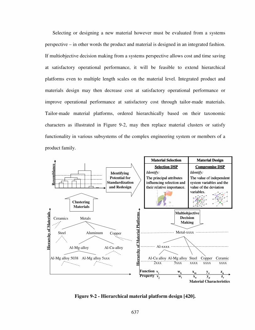
637
Selecting or designing a new material however must be evaluated from a systems
perspective – in other words the product and material is designed in an integrated fashion.
If multiobjective decision making from a systems perspective allows cost and time saving
at satisfactory operational performance, it will be feasible to extend hierarchical
platforms even to multiple length scales on the material level. Integrated product and
materials design may then decrease cost at satisfactory operational performance or
improve operational performance at satisfactory cost through tailor-made materials.
Tailor-made material platforms, ordered hierarchically based on their taxonomic
characters as illustrated in Figure 9-2, may then replace material clusters or satisfy
functionality in various subsystems of the complex engineering system or members of a
product family.
Aluminum
Al-Cu-alloyAl-Mg-alloy
Al-Mg alloy 5xxx
Steel
Hie
rarc
hy
of
Ma
teri
als
Metals
Al-Mg alloy 5038
Hie
rarc
hy
of
Ma
teri
al
Pla
tfo
rms
Al-xxxx
Metal-xxxx
......
Res
emb
lan
ce
Clustering
Materials
Identifying
Potential for
Standardization
and Redesign
Multiobjective
Decision
Making
Al-Mg alloy
5xxx
Steel
xxxx
Function
Property
Copper
Ceramics
wk
wl
xm
xn
yo
yp
zq
zr
Ceramic
xxxx
Copper
xxxx
vi
vj
Al-Cu alloy
2xxx
Material Characteristics
Compromise DSP
Identify:
The value of independent
system variables and the
value of the deviation
variables.
Selection DSP
Identify:
The principal attributes
influencing selection and
their relative importance.
Material DesignMaterial Selection
Compromise DSP
Identify:
The value of independent
system variables and the
value of the deviation
variables.
Selection DSP
Identify:
The principal attributes
influencing selection and
their relative importance.
Material DesignMaterial Selection
Figure 9-2 - Hierarchical material platform design [420].
638
Numerical taxonomy is a systematic scientific approach to define what to standardize
for which members in a family of either products, materials or even processes. This
approach is based on identifying similarity patterns in an existing product or material
portfolio by means of clustering and subsequent taxonomy (hierarchical platform)
construction either on multiple levels or scales. The benefits are that i) we do not have to
rely on any predetermined grouping in the data, ii) data is available, and iii) the approach
is domain independent. Design of hierarchical platforms facilitates affordable and
effective adaptation of complex engineering systems and product families as their
application and requirements change. By harnessing the nearly limitless information
which exists today, it facilitates the quick adaptation to dynamic demands. This flexibility
is crucial to achieve continuous improvement in redesigning complex engineering
systems and consequently remain competitive in the global marketplace and distributed
design environment of the future.
In future work, systematic materials design efforts should not stop at the design of
material platforms or families, but also include designing materials for:
i) modularity, i.e., allowing for changes in function and form,
ii) mutability, i.e., allowing for changes in form but not function,
iii) robustness, i.e., insensitivity to small variations but not changes in function and
form.
Combining design for modularity, mutability, and robustness, one should also investigate
the designing reconfigurable materials in the context of open engineering systems.
639
Developing an holistic materials design method including solids and fluids:
Furthermore, developing an holistic materials design methodology, that is not
characterized by multiple ownership of different disciplines, should be focus of future
research. Materials must be defined generally, not in terms of their state, e.g., solid or
fluidic, nor in terms of their composition, e.g., semiconductors or non-semiconductors,
metals or non-metals, etc. State or composition of a specific material should be the
outcome of a problem-directed systematic design approach, not its constraints. In any
case though, the integrated design of products and materials from a systems perspective
involves computationally expensive modeling or extensive testing efforts. Therefore, in
the context of integrated product and materials design, strategies to manage complexity,
as for example developed in this work, are crucial. Limitations of the value-of-
information-based strategies developed in this work and opportunities for future work in
this domain will be addressed in the following section.
9.4.2 Limitations and Opportunities for Future Work – Value-of-Information-Based Strategy to Systematic Design-Process Design
The possible directions for future work with respect to value-of-information-based
strategy to systematic design-process design, as summarized in Table 9-2, are discussed
in the following.
640
Facilitating design-process synthesis and defining fundamental design-process
building blocks:
The decision-centric paradigm followed in this dissertation involves that design-
processes can be viewed as modular, hierarchical systems, with sybsystems and
interfaces between these subsystems. Design-processes are comprised as a network of
analysis models and decisions, modeled in terms of decision and interface templates
[572]. Prior work [79, 201, 330, 434, 482, 499] has shown that human decision-makers
make two types of decisions – compromise and selection – and that design activities from
design-processes to enterprises can be modeled in terms of decisions, information
transformations (analysis models), and interactions. Also, computational templates within
decision templates and interaction patterns between models or decisions have been
defined from a decision-centric perspective [478]. Future work should involve extending
this decision-centric design paradigm towards a basic design equation.
The use of currently defined basic design-process building blocks should be
increasingly leveraged as patterns that compose emerging design-processes of complex
engineered systems. Fundamental patterns could then be classified in, for example,
design catalogs to facilitate their use for design-process synthesis. Ultimately, a
framework that automatically configures design-processes based on specified
performance requirements through computational design synthesis should be investigated
in future work. Ideally, those patterns would be modeled as agents from which
embodiment design-processes emerge. Nevertheless, the tradeoff between the cost of
adding more information to a design-process and the possibility of achieving benefits in
terms of the better decision remains, as discussed in the following.
641
Enhancing the value-of-information-based Process Performance Indicator:
The value-of-information-based concept has proven to be useful when making such
meta-design decisions. In this dissertation, focus has been on the scenario of generating
and selecting design-process alternatives by replacing fundamentally different analysis
models that embody fundamentally different assumptions when knowledge of a truthful
design-process or its error bounds throughout the whole design space is not available.
Generating and selecting design-process alternatives by replacing interaction pattern has
been the focus of prior work for scenarios in which error bounds throughout the whole
design space are available [478]. However, current value-of-information-based metrics
can be improved further to be used in more complex design scenarios.
For example, the Process Performance Indicator provides information about the
overall design-process performance from a decision-centric perspective only. It does not
quantify the influence of individual dimensions of refinement. It only provides
information about whether the model should be refined, not how. In other words, only the
combined effect of refinement is calculated. Hence, further investigation needs to be
carried out for different types of refinement of design-process alternatives, such as
considering additional physical phenomena, adding more parameters, coupling physical
phenomena, developing better models of physical phenomena, etc. Also, the
characterization of refinement should be such that a designer is able to isolate the effect
of different types of refinement, not the combined effect of refinement.
Also, the cost of improving analysis models is not directly included in the Process
Performance Indicator. In its current formulation, only information about benefit
achieved in terms of the overall utility is included. However, cost can be included in the
642
overall utility function once meaningful const information becomes available. Since
value is generally defined as a qualitative function of benefit (quality) and cost, cost
evaluation in the conceptual and early embodiment stages addressed in this dissertation is
delegated to the judgment of the human decision maker. The basic premise is that the
human decision maker is better able to process qualitative information and make a more
meaningful subjective (not arbitrary) cost evaluation when judging the variety of cost
factors, such as a company’s resources, organizational structure, strategic goals, available
time-to-market, prime and overhead costs, etc., at hand.
In formal decision making, replacing analysis models with fundamentally different
models based on different physical assumptions must be facilitated. The Process
Performance Indicator developed in this work is only a first step in this direction. For
example, more advanced strategies to determine at which points in the design space the
Process Performance Indicator is evaluated should be developed. Also, the value-of-
information-based metrics developed so far can be improved further to be used in more
complex design scenarios.
Extending value-of-information-based concept to other domains:
At the same time, applicability of the value-of-information-based concept to other
domains, such as experimental research, should be extended to achieve further integration
of bottom-up science with top-down engineering as described in Chapter 5. For example,
consider the scenario of measuring velocity profiles in a specific fluid flow application.
Several experimental techniques, such as Pulsed Ultrasound Doppler Velocimetry or
Particle Image Velocimetry, as well as several simulation-based techniques, such as
643
Lattice Boltzmann Code, are available. To satisfy performance requirements, parameters
of the fluid or setup could be varied to better achieve certain design goals. Future work
should thus involve using the Process Performance Indicator in such scenarios to decide
on the experimental or simulation-based technique that is best suited for finding the
parameters of the fluid or setup during embodiment design to satisfy a designer’s
preferences best. Other scenarios including prototype testing should also be investigated.
Using multiple metrics simultaneously for design-process design:
Furthermore, the design of design-processes is based only on a single metric – value
of information – in this dissertation. There can be various other ways in which the
effectiveness of design-processes can be measured, such as robustness, modularity,
adaptability, complexity, accuracy, etc. However, the design of design-processes would
be more efficient if instead of using such indirect metrics, design-processes can be
directly evaluated for some direct metrics such as cost and time. However, evaluation of
design-processes is a complex task and requires the development of mathematics to
represent design-process related information and its transformation. Nevertheless,
designing design-process using multiple metrics simultaneously is a promising area of
future work.
Investigating more complex networks of decisions and models using value-of-
information-based metrics:
Value-of-information-based metrics should be applied to more complex design-
processes, where design-process alternatives are generated by refining/simplifying
644
interactions and analysis models concurrently. These design-process alternatives should
resemble a complex network of decisions and information transformations on multiple
levels and scales, stretching from embodiment to detail design phases. Also, these design-
process alternatives should involve multiple decentralized decisions interacting through
game-theoretic protocols implemented in interface templates [572] for testing value-of-
information-based metrics in a distributed collaborative environment where design-
process activities are carried out by distributed agents. Also, when designing more
complex networks of decision and information transformations, use of preemptive goal
formulations should be investigated to better integrate the design of embodiment design-
processes with product and materials design.
Designing open design-processes including design-process platforms and families:
The objective in designing embodiment design-processes is to design customized
design-processes for a specific principal solution developed in response to a specific
design problem. However, it is shown that the design of design-processes depends
significantly on the preferences of designers for different objectives, which in turn
depend on dynamic demands. In order to increase design-process flexibility, it is
recommended to design open design-processes, analogous to open engineering systems
[597]. Hence, designing design-process for modularity, mutability, and robustness, which
results in reconfigurable design-processes or platforms and families of design-processes,
is to be addressed in future work. Design-processes can then be customized easily based
on dynamic demands by exploiting reusability and scalability. Especially the design of
design-process platforms and families is an interesting research field and has not yet been
645
exploited.
A related area of interest is the consideration of enterprise structure and anticipation
of a product’s life cycle processes during conceptual design. During conceptual design,
mostly feasibility of a design is currently analyzed. Time-to-market factors, value-chain
considerations, cultural aspects, etc. should be integrated to provide companies a greater
edge over their competitors in the global marketplace. Hence, integrated product and
process design models at the conceptual phase are imperative to reduce errors, costs and
product lead time, as well as consider a product’s lifecycle processes (such as material
and product processing, handling, use, recycling and end-of life processes) and value
chains along with designing design-processes. This leads to integrated product, materials,
design-process, and enterprise design, as addressed in Section 9.5.
9.4.3 A Note on Future Work on the Design Example Problems
Having discussed limitations and opportunities for future work with respect to
function-based systematic conceptual design in Section 9.4.1 and with respect to the
value-of-information-based strategy to systematic design-process design in Section 9.4.2,
opportunities for future work with respect to the design example problems are addressed
in this section.
646
Reactive material containment system:
In the context of the reactive material containment system example, embodiment
design efforts should be extended to the detail design phase in future work, involving the
integrated design of multifunctional energetic structural materials and multifunctional
blast resistant panels. Also, the effect of impacts and solid fragments of varying size and
velocity as changes in temperature is to be considered. Moreover, phenomena occurring
in the context of blasts due to explosions, blast loading of materials mesostructures, as
well as fracture and fragmentation are to be considered through multiscale analysis.
Furthermore, design and testing of full-scale prototypes should be investigated. However,
with respect to blast resistant panels in particular, designing associated materials on
length scales lower than microscales should be considered in future work.
For example, martensitic transformation concepts applied to energy absorbing
systems should be focus of future research, acknowledging time for diffusion processes
during blast loading. However, ideally, designing alloys on nanoscales should be
addressed to increase energy dissipation in for example out-of-plane honeycomb
sandwich structures. One possibility is to input stress-strain relations from phase field
simulations directly into existing FEM-simulation models for rapid design-process
exploration. For increased energy dissipation, the goal should be to maximize the plateau
stress level and densification strain. Designing the nanostructure of either alloys or
extruded powder metals or metal oxides in addition to the micro- and meso-structures is a
promising future research endeavor to better achieve this goal. Also, the design of
nanolayered surface coatings or textures (achieved through for example combined heat
647
treatment and deformation processing such as rolling) for functional enhancement (such
as wear, fracture, fatigue, and temperature resistance) may be considered.
Furthermore, modeling of various mesostructure energy dissipation features such as
sliding plates, crushing of cellular materials, or granular flow should be enhanced.
Promising granular flow enhancements include filling cellular materials with for example
compressible, shearable, and irregularly shaped talcum powder, ceramic particles, or
other unconfined granular material for combining shear-dominant martensitic
transformation of deformable cellular materials with large shear strain energy absorption
provided by frictional dissipation in granular filler materials. Also, varying topological
arrangement to maximize shear deformation is of future research interest. Moreover,
enhancing modeling efforts through coupled fluid-structure analysis of blast resistant
panels or computational fluid dynamical analysis of shear transformations through for
example Latice Boltzmann codes is an exciting area of future investigations.
Furthermore, introducing various form of nanoreinforcements is a promising area of
research endeavors.
Optoelectronic communication system:
In the context of designing photonic crystal waveguides for a next-generation
optoelectronic communication system, future work should be focused on overall system
aspects. Having made the first step of designing photonic crystal optical couplers and
slow-light waveguides, the next step should be focused on integrating photodetectors.
Preliminary work exists but various difficulties with respect to system integration have
been revealed and should be addressed. However, successful system integration is an
648
excellent test for advanced robust design techniques and enhanced strategies for
managing complexity in complex networks of decisions and models.
At the same time, future work should include extensive efforts on generating and
exploring other promising optoelectronic communication system concepts. Results may
then lead to design catalogs of solution principles associated with the photoeffect
phenomenon. Design of various photodetoctor concepts seems to be the most promising
starting point. However, even though the design of optoelectronic structures and devices
in the context of integrated product and materials design is very challenging and has it’s
own nuances different from the more traditional materials design domain for non-
semiconductors, it is a fruitful research area and essential to the development of a holistic
materials design method.
9.5 A Vision for Research in Design
Having discussed specific limitations of this work and opportunities for future work,
long-term research goals and the author’s vision for research in design are addressed in
this section.
As described in Section 1.1.1, facing dynamic demands on limited resources as well
as growing consumer bases in a global marketplace, design flexibility is crucial. Focus in
this work has been on i) concept flexibility, asserting that the majority of resources is
committed during the conceptual design phase, and ii) design-process flexibility,

649
asserting that a company’s core intellectual property are design-processes. The integrated
design of product and material concepts and associated embodiment design-processes
based on a function-based systematic approach facilitated through design catalogs and a
value-of-information-based strategy are proposed in this work to increase a designer’s
flexibility, particularly a designer’s concept and design-process flexibility. However, the
problem directed approach to integrated product, material and design-process design
presented in this work is only a first step to achieve my research vision for engineering
design.
I envision that the global marketplace of the future will be defined by global diversity
and consumerism. In the changing, distributed environment of the future, requirements as
well as technological capabilities will change rapidly, elements of an enterprise will be
distributed geographically and multiple agents will be engaged in product realization.
New advanced technologies will be developed and deployed at an accelerated pace.
Hence, companies must be prepared to both drive and respond to the even faster creation,
evolution and synthesis of new technologies and products.
In this context, a company must then be able to respond to dynamic demands
promptly. Hence, it’s intellectual capital must relate to the acquisition of product or
process information and the tools for transforming this information for an engineering
enterprise to remain agile with respect to the constantly evolving demands of a global
market. Consequently, product knowledge, process knowledge and tools for creation,
management and dissemination of knowledge present the unique product and enterprise
related intellectual capital. Intellectual capital is an integral part of the enterprise’s core
competencies and therefore cannot be outsourced.
650
In order to survive global competition, enterprises will continue creating the highest
possible value while sourcing at lowest cost. Detailed product design to the specifications
can be outsourced to remain competitive in the future global marketplace. Commodity
work [411], i.e., work in any professional domain (e.g., engineering, law, economics,
medicine) that can be digitized and handled separately or that can easily be substituted,
will be transferred to lower-wage but equally qualified locations in newly industrializing
countries. However, design and realization of complex engineering systems require
critical judgment close to specific markets especially in the early design phases that
cannot be outsourced, as illustrated in Figure 9-3. Designing complex engineering
systems involves anticipating its life-cycle processes, such as usage processes, recycling
processes, etc., before any physical realization processes are initiated.
Due to progressing specialization required during systems realization, it also involves
anticipating the best enterprise structure from a problem-directed or systems perspective.
Nevertheless, integrated design of product, materials, design-processes and enterprises
may indeed not be possible in certain scenarios. In some scenarios, the design of design-
processes may dictate the organization structure. In other scenarios, the organizational
structure dictates the design of design-processes or imposes additional constraints on the
design of design-processes. But, emerging flexible organizational structures seem to
make a problem-directed approach to integrated design of products, materials, design-
processes and enterprises possible.
In this context, I envision that conceptual design is significantly interlinked not only
with the design of embodiment design-processes, but also the design of a product’s
lifecycle processes, an enterprise’s value chains, and ultimately the organizational
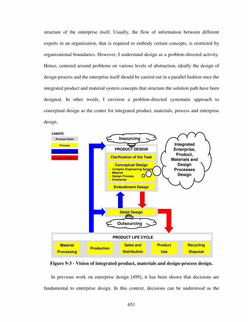
651
structure of the enterprise itself. Usually, the flow of information between different
experts in an organization, that is required to embody certain concepts, is restricted by
organizational boundaries. However, I understand design as a problem-directed activity.
Hence, centered around problems on various levels of abstraction, ideally the design of
design-process and the enterprise itself should be carried out in a parallel fashion once the
integrated product and material system concepts that structure the solution path have been
designed. In other words, I envision a problem-directed systematic approach to
conceptual design as the center for integrated product, materials, process and enterprise
design.
Clarification of the TaskClarification of the Task
Conceptual DesignConceptual Design- Complex Engineering System- Material- Design Process- Enterprise
Embodiment DesignEmbodiment Design
Detail DesignDetail Design
MaterialMaterial
ProcessingProcessingProductionProduction
ProductProduct
UseUse
RecyclingRecycling
DisposalDisposal
PRODUCT DESIGNPRODUCT DESIGN
PRODUCT LIFE CYCLEPRODUCT LIFE CYCLE
Process Chain
Process Anticipation
Process Definition
Process
Legend:
Sales andSales and
DistributionDistribution
Integrated Enterprise,
Product, Materials and
Design Processes
Design
Outsourcing
Insourcing
Figure 9-3 - Vision of integrated product, materials and design-process design.
In previous work on enterprise design [499], it has been shown that decisions are
fundamental to enterprise design. In this context, decisions can be understood as the
652
domain-independent adhesive gluing organizational structure, value chains, realization
processes, information flow across organizational entities, as well as communication,
cooperation, and coordination protocols within the enterprise so that the configured
enterprise behaves as an integrated whole, therefore enhancing its overall value creation,
flexibility, and reactivity. Besides generic enterprise reference architectures and modules
as well as universal enterprise modeling languages and tools, a decision-centric
perspective is thus key even in a world envisioned as a flat playing field for individuals
by Friedman [219].
Conceptual design is still a necessary prerequisite to any decision-centric design
activity. A decision-centric approach to designing products, materials or even enterprises
requires concepts to be embodied as an input, as described in Section 2.1.1. Any
decision-centric approach should thus be driven by problem-directed conceptual design
approaches. Hence, focus should be on integrated conceptual design first, and then on
associated decision-centric embodiment design-process or enterprise design-processes.
First steps towards facilitating integrated conceptual design have been made in this
dissertation. Focus has been on integrated design of product and material concepts,
operating at the level of solution-neutral functions, phenomena and associated solution
principles. However, increased conceptual design research efforts are required. This
involves bringing design again closer to the fundamental sciences of physics, chemistry,
biology, etc., that are more and more ignored in design. Reducing complexity through
abstraction to phenomena of the fundamental sciences has shown to contribute
significantly to the development of design processes, i.e., reducing a solution-neutral
653
problem statement to a set of functions linked with scientific phenomena represents a
fundamental asset for design-processes.
I envision design as an open-ended synthesis activity, based on a human-computer
partnership – hence, going far beyond simulation-based design. Thus, the perspective of
design as a multilevel or multiscale modeling activity followed by executing simulations
is extremely limited. As described in Section 9.4.1, imagine the possibilities inherent in a
function-based approach to conceptual materials design as compared to materials design
limited to the embodiment design phase driven by multiscale modeling. Being able to
arrive at a functional materials representations opens the door to a variety of design
methodologies, such as principle driven design approaches, theories of inventive problem
solving, human or computational synthesis techniques, complexity management
strategies, tools to direct emergent behavior, self organization, repair, etc.
What is required are design methods and strategies for increased concept flexibility,
i.e., concept generation, and also increased design-process flexibility, i.e., innovation and
complexity management. Strategic approaches for managing intellectual capital
comprised of product and (design-)process related knowledge are and will remain crucial.
However, as addressed in this dissertation, research focus should include bringing
together bottom-up (experimental testing) with top-down (design). In this work,
experimental and prototype testing has been integrated with a decision-centric strategy to
design-process design. However, efforts in this direction are to be extended, as described
in Section 9.4.2.
In this work, it is asserted that integrated design of product and material concepts and
associated embodiment design-process based on set-based theories will have much
654
greater leverage than merely considering the design of product concepts followed by
materials design during the embodiment design phase. Designing associated
organizational structures of the enterprise along with the embodiment design-processes is
envisioned to further increase flexibility and be fundamental to a company’s success
when designing in a distributed environment for a global marketplace. Moving towards
integrated product, materials, design-process, and enterprise design, the underlying
research questions become:
• How can integrated product, material, (design- and life-cycle-)process, and
enterprise design methods be realized?
• How can science-based bottom-up with design-based top-down techniques be
further integrated?
• Since materials have always been the key to innovation, how can the function-
based materials design approach presented in this work be further extended to
bring materials design even closer to designing materials?
In order to answer these research questions, I propose the following steps based on my
work:
• Extending existing and creating new phenomena and associated solution
principles design catalogs for integrated product, materials, (design- and life-
cycle-) process, and enterprise design
• Extending the use of design principles to the materials and enterprise domain
• Enhancing conceptual design synthesis techniques
• Developing an holistic conceptual design method
• Refining modeling and selection tools for function-based systematic design
655
• Investigating fundamental design-process building blocks
• Enhancing the value-of-information-based concept
• Refining intellectual capital management
• Extending the open engineering system philosophy
However, so far, it must be acknowledged at all times, that development of new
breakthrough materials has mostly been based on “accidents” that allow and sometimes
force the discovery of new structures – a logical consequence of a shear infinite design-
space supporting my claim that there is more to design than automated search and
simulation. In this context, Smith [610] argues that the “great success of the logical
analytical reductionist approach to understanding over the last four centuries and the
utility of the application of its simple principles has not negated the evidence of history
that the sensual-emotional-aesthetic capabilities of the human being also have validity.
The world is far to complex to be modeled scientifically. However, the human brain has a
structure that gives it the capacity for relating to the world in its undivided complexity in
ways that are not logical, though they are effective.” Or, in Democritus’ words:
“everything existing is the fruit of chance and necessity”.
The key to design is thus an interplay of multiscale/-level modeling and synthesis
with human decision-making. In this context, the function-based systematic approach to
the integrated design of products (complex systems), (perhaps multifunctional) materials,
associated embodiment design-processes, and overarching organizational structures may
serve as the center for a human computer partnership. The problem remains to find the
proper nonexclusive role of each partner.
656
APPENDIX A: LITERATURE REVIEW AND
THEORETICAL FOUNDATIONS DESIGN CATALOG
SOLUTION PRINCIPLES ASSOCIATED WITH
(IN)ELASTIC DEFORMATION
In the following, theoretical foundations to the development of the solution principle
design catalogs are presented. The focus is on compression, tension, torsion, bending,
inversion, splitting, and flattening of structures, crushing of cellular materials, microtruss
structures, textile-based weaves, fibrous composite structures, multi-length-scale
composites, auxetic structures, and microtruss mechanisms, as well as martensitic
transformations.
I) Compression of Structures
Simple struts made of mild steel [507], struts with an initial imperfection (deflection)
[240] have been analyzed as impact energy absorbers. Struts buckle elastically in the
primary phase of the impact during which attached end-masses experience large transient
decelerations. The remaining kinetic energy is dissipated in plastic hinges which are
considered to form at the points of maximum curvature in the elastic buckling mode.
However, because of the limited zone of plastic deformation, i.e., one plastic hinge, the
absorbed energy per unit mass in static tests is minimal. With respect to buckling and
plastic collapse however, the specific ultimate tensile strength is an excellent indicator of
657
the ability of a material to absorb energy [667]. The uniform elongation parameter is
unimportant provided that the ductility is sufficient to allow the requisite plastic folding.
II) Tension of Structures / Nanotubes
Another simple type of energy-absorber involves the uniaxial plastic extension of
ductile wires, strips and tubes or even nanowires. The maximum energy that can be
absorbed per unit weight before tensile instability supervenes depends upon the ultimate
tensile strength and strain. Assuming constancy of volume and a simple power law
relationship between the true stress and true plastic strain, Thornton and Magee [667]
derive a quantitative relationship between these parameters and the tensile energy
absorption in order to provide a criterion for the ranking of materials for use as energy
absorbing media. Thus, to maximize tensile energy absorption, a high ultimate tensile
strength and high uniform elongation are required. Consequently, cold worked steels
have poor tensile energy absorption and conversely metastable austenitic steels have
superior tensile energy absorption.
However, even though tension devices are a simple type of energy absorber, they
suffer from the stroke, i.e., maximum displacement, limitation imposed by the ultimate
strain. Also, most conventional structural materials do not simultaneously possess high
stiffness, high strength, high strain and low density. For example, most metals have high
stiffness and strength as well as potentially sufficient ductility, but, they are also very
dense. On the other hand, common elastomers possess high ultimate strains, but they
658
have relatively low stiffness and strength. Also, many conventional composite material
have large stiffness and strength to density ratio, but many lack sufficient ultimate strain.
This lack of multifunctionality in common materials is why there is a need to study and
develop more advanced material systems.
Carbon nanotubes are the most promising nanostructured materials of extraordinary
mechanical, electrical and thermal properties that may be used for uniaxial tension energy
absorbers. More specifically, a carbon nanotube is a hexagonal network of carbon atoms
rolled up into a seamless, hollow cylinder, with each end capped with half of a fullerene
molecule [559]. In general, it is only a carbon nanotubes isotropic topology that
distinguishes it from other carbon structures and gives it unique properties. Since carbon-
carbon covalent bonds are among the strongest bonds in nature, a structure based on a
perfect arrangement of these bonds oriented along the axis of the nanotubes produces a
very strong material with an extremely high strength-to-weight ratio.
Properties of various types of carbon nanotubes are reviewed in great detail by Breuer
and Sundararaj [80] or Christodoulou and Venables [135]. In summary, they have an
extraordinary high tensile strength, low density and high Young’s modulus. The most
striking effect however is the combination of high flexibility and strength with high
stiffness. Thus, nanotubes are very stiff for small loads, but turn soft for larger loads,
accommodating large deformations without breaking. Hence, carbon nanotubes have an
extraordinary potential in energy dissipation applications. At the same time, they have a
unique electronic character, ranging from high-conductivity metallic behavior to
semiconducting with a large band gap. Their excellent electrical and thermal properties
yield them particularly important in nanocomposites, making for example conjugated
659
polymers mechanically stronger, more conductive and less susceptible to thermal
degradation. Carbon nanotubes’ interesting optical properties, which do not occur in
larger micron-scale carbon fibers, arise from low dimensionality and an unique electronic
band structure. Their low turn-on fields and high current densities characterize their
electrical properties. But, experimental results show that the strength of carbon nanotubes
is lower than that predicted by theory [80]. Nevertheless, structures with incorporated
carbon nanotubes could be substantially stronger and lighter than conventional
aluminum, alloys and carbon fiber-reinforced polymer composites. However, the real
value of carbon nanotubes lies in their range and breadth of properties, namely, their
electrical, thermal, magnetic and optical properties. These properties provide additional
benefits, which enable development of multifunctional, structural materials. Currently
however, one of the major obstacles to using carbon nanotubes is cost. However,
advances in the synthesis of carbon nanotubes continue to rapidly improve cost and
quality, though growing structurally perfect nanotubes at large scales is not yet at hand.
III) Torsion of Structures
Besides tension and compression, torsion of bars or tubes has been used in energy
dissipation devices [195]. For example, Yu and Johnson [759] have studied the behavior
of helical springs being pulled straight under axial load. The dominant energy absorbing
mechanism is plastic torsion, and a system is described for arresting vehicles which as a
large deceleration stroke. Analogous to tension, the maximum energy that can be
660
absorbed per unit weight before torsional instability supervenes depends upon the
ultimate torsional strength and strain. Besides the maximum stroke limitation, energy
absorbers based on torsion suffer from the unavailability of lightweight materials that
combine high ultimate torsional strength and strain.
IV) Bending of Plate Structures
Prominent structural energy absorbers are based on plate bending. Here, kinetic
energy of an incoming blast impinging on a plate is dissipated by bending and stretching
deformations. Assuming the pulse to be uniformly distributed over the plate and the base
material to be rate-independent and perfectly plastic with yield stress, the plastic work per
area dissipated for the bending of simple plates becomes [752]:
+
=
LL
hh
Lhw yypl
δσ
δσ
2
3
2 Equation 14
where h is the thickness, L the width, δ the deflection and σy the yield strength of the
plate. However, energy dissipation caused by plate bending and stretching is also
encountered in the front face sheet in sandwich panels.
Sandwich panels, i.e., structural member made up of two stiff, strong skins separated
by a lightweight core, can be used to enhance energy storage functionality. However,
sandwich panels can also be leveraged to enhance energy dissipation functionality. For
example, in the context reactive material containment system example, energy dissipation
in sandwich panels can be described with the three stage deformation theory, developed
by Fleck and Deshpande [210]:
661
Stage 1: One-dimensional fluid-structure interaction problem during the blast event
resulting in an uniform velocity being imposed on the outer face sheet.
Stage 2: Core crushing during which the velocities of the faces and core equalize
by momentum transfer. It is envisaged that the core is crushed by the
advancing outer face sheet, and consequently the outer face sheet is
decelerated by the core while the core and the rear face of the sandwich
beam are accelerated. For simplicity, the reduction in momentum due to
the impulse provided by the supports is neglected. This approximation is
motivated by noting that the time period of this phase is much smaller than
the overall structural response time.
Stage 3: Retardation phase during which the beam is brought to rest by plastic
bending and stretching.
This three-stage deformation theory has been used to calculate the transverse
displacement (and longitudinal tensile strain accumulated) of a variety of sandwich
panels as a function of the magnitude of blast loading. The superior performance of
sandwich plates relative to solid plates of equal mass for shock loading is due (i) the
substantial bending strength of a sandwich plate as described above, and (ii) energy
absorption by the sandwich core. Leveraging advanced core topologies (mostly metal
structural components), more than half of the kinetic energy initially imparted to a
sandwich plate by intense short duration pressure loadings can be absorbed. Over the last
decade, a number of core topologies for sandwich panels have emerged, showing
advantage over monolithic structures, as reviewed below.
662
However, to be valid, this approach requires that the characteristic pulse period, t0, be
small compared to the period of the first stage when the top face sheet flies into the core,
i.e., small compared to 0.005L/(σy/ρ)1/2 . For stainless steel plates with L = 1 m, this
requires that t0 to be small compared to 3.5 x 10⁻⁴s. A blast pulse with t0 = 10-4 meets this
requirement, but, only marginally. Also, this approach assumes that the core and the back
face sheet do not deform in the initial stage. Furthermore, in the following analyses, blast
in air are assumed. In contrast to for example water blasts, core strength has no effect on
the momentum transfer for water blasts [752].
IV a) Solid Plate Models
Plates are initially flat structural elements, having thicknesses much smaller than the
other dimensions. Here, only small deflections of isotropic, homogeneous, elastic, thin
plates are considered (i.e., the ratio of the thickness to the smaller span length should be
less than 1/20) – a simplification consistent with the magnitude of deformation
commonly found in plate structures. The fundamental assumptions of the small-
deflection theory for isotropic, homogeneous, elastic, thin plates as applied in this
simulation study are based on the geometry of deformations, i.e., Kirchhoffs hypotheses:
• The deflection of the midsurface is small compared with the thickness of the
plates. The slope of the deflected surface is therefore very small and the square of
the slope is a negligible quantity in comparison with unity.
• The midplane remains unstrained subsequent to bending.

663
• Plane sections initially normal to the midsurface remain plane and normal to that
surface after bending (i.e., vertical shear strains are negligible and normal strain
resulting from transverse lading may also be omitted).
• The stresses normal to the midplane are small compared with other stress
components and are neglected in correspondence with St. Venaint’s principle.
This supposition becomes unreliable in the vicinity of highly concentrated
transverse loads or in narrow edge zones, particularly near the corners of plates
and around holes with diameter of the order of magnitude of the plate thickness
itself.
When the deflections are not small, the bending of plates is accompanied by strain in
the midplane and the first two assumptions are inapplicable. Also, in thick plates, shear
stresses are important. Thick plates are treated by means of a more general theory owing
to the fact that the last two assumptions are no longer appropriate. However, small- and
large-scale tests have shown validity of Kirchhoff’s hypotheses. In the vast majority of
engineering applications, adequate justification may be found for the simplifications
stated with respect to the state of deformation and stress.
Based on these assumptions, the basic differential equation for the deflection of
isotropic, homogeneous, elastic, thin plates based on Kirchhoff’s assumptions is readily
derived to be
D
pw=∇4
with Equation 15
( )2
3
112 ν−=
EtD
Equation 16

664
where 4∇ equals to the square of the Laplace operator, w is the plate deflection
(displacement in z-direction), p is the intensity of distributed transverse load per unit area
(pressure), D is the flexural stiffness, E is the modulus of elasticity, t is the plate
thickness and ν is Poisson’s ratio.
The exact theory of plates is exclusively governed by the theory of elasticity. Except
for simple types of loading and shapes, such as axissymmetrically loaded circular plates,
the governing plate equation yields plate deflections only with considerable difficulty.
Hence, the focus in this conceptual stage is on plates infinitely long in one direction, or
very long and narrow rectangular plates, called plate strips.
fixed
fixed
b
x
y
z
Figure A-4 - Clamped plate infinitely long in one direction.
Since the loading described deforms the plate into a cylindrical surface possessing its
generating line parallel to the x-axis,
0=
∂
∂
x
w
and
0
2
=∂∂
∂
yx
w
. Therefore,
D
pw=∇4
reduces
to
D
p
dy
wd=
4
4
. Since the bent plate surface is of developable type and the edges are free to
move horizontally, the formulas derived in this case also hold for large deflections (w > t
but w < b, where b is the plate thickness).
665
Assuming a uniform pressure p0, integrating successively four times, and satisfying
the boundary conditions of the two-sided clamped plate (w = 0 and
0=
∂
∂
y
w
at y = 0 and y
= b), plate deflection becomes:
2
2
03040
241224y
D
bpy
D
bpy
D
pw +−=
Equation 17
Thus, the maximum deflection at
2
by =
equals to:
D
bpw
384
4
0max =
Equation 18
Analyzing a fully clamped square plate, the solution becomes [9]:
D
bpw
4
0max 00133.0= Equation 19
The use of rigidities in plate structures may significantly increase a plate’s stiffness.
Stringer stiffened plates are among the most efficient for applications requiring light
weight [190, 191]. For example, hat-stiffened plates are generally regarded to be one of
the most efficient light weight constructions for compression panels loaded in direction,
waffle-stiffened plates for compression panels loaded in two direction. However, based
on approximations derived using analytical techniques, equivalent or transformed
orthotropic plates can be constructed as a replacement models. For example, in the case
of a plate reinforced by ribs, the bending stiffness of the ribs and the plating are
combined and taken to be uniform across the replacement model. Subsequently,
orthotropic plate moduli and Poisson’s ratios are approximated giving the rigidities. As
proposed by Ugural [9], the flexural stiffness for both in-plane principles axes of a plate
reinforced by equidistant rectangular stiffeners becomes
666
( ) ( ) s
tbEEbt
s
IEEbtD sssss
rf12112112
3
2
3
2
3
+−
=+−
=νν
Equation 20
where Es is the elastic modulus of the stiffeners, Is is the moment of inertia of the
stiffener cross section with respect to the midplane of plating, ts is the height of each
spacer, bs is the thickness of each spacer and s is the spacing between centerlines of
stiffeners as shown in Figure A-5.
s
tsbs
b
t
b
s bs
bbs
s
Figure A-5 - Plate reinforced by equidistant rectangular stiffeners (side and
top/bottom view).
For a plate reinforced by a set of equidistant rips, as shown in Figure A-6, the flexural
stiffness for both in-plane principles axes becomes according to Ugural [9]:
( ) ( )( ) ( )( )
s
thsht
thshttthsht
thshtE
s
EID
r
rrr
r
Trf
−+
−+−−+−
−+
==
22233
2
1
3Equation 21
ts
trh
b
s
b
s h
bh
s
Figure A-6 - Plate reinforced by equidistant rips (side and top view).
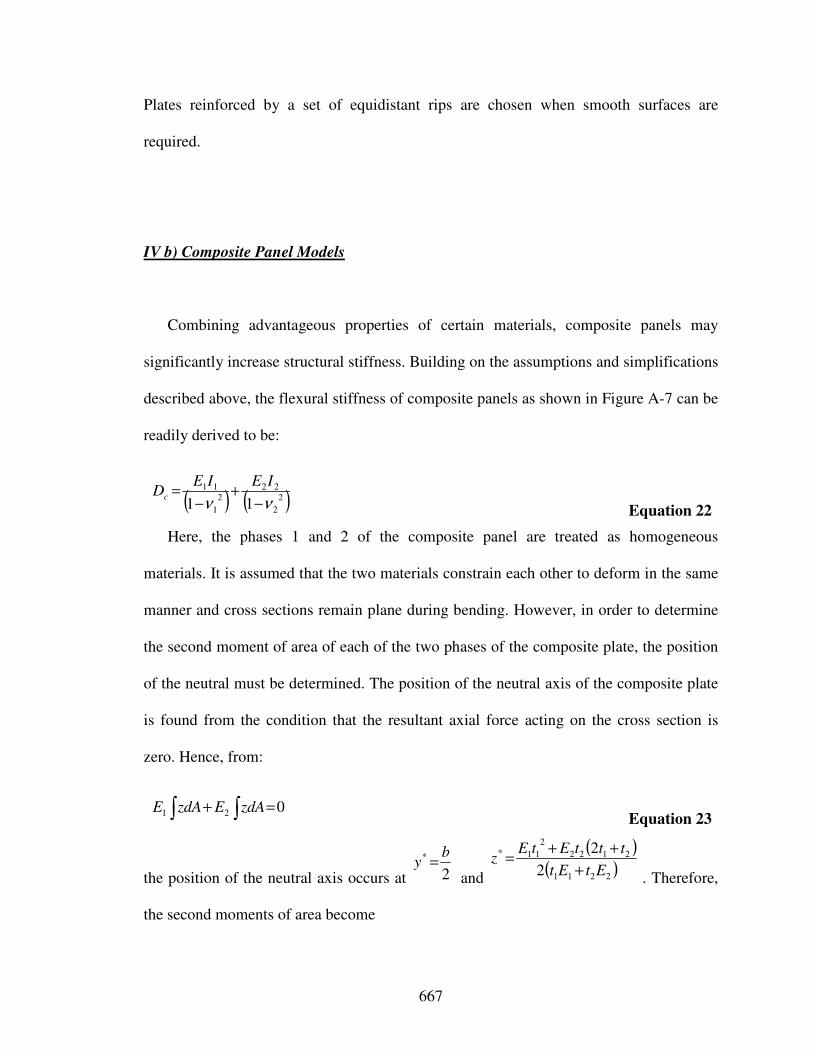
667
Plates reinforced by a set of equidistant rips are chosen when smooth surfaces are
required.
IV b) Composite Panel Models
Combining advantageous properties of certain materials, composite panels may
significantly increase structural stiffness. Building on the assumptions and simplifications
described above, the flexural stiffness of composite panels as shown in Figure A-7 can be
readily derived to be:
( ) ( )2
2
222
1
11
11 νν −+
−=
IEIEDc
Equation 22
Here, the phases 1 and 2 of the composite panel are treated as homogeneous
materials. It is assumed that the two materials constrain each other to deform in the same
manner and cross sections remain plane during bending. However, in order to determine
the second moment of area of each of the two phases of the composite plate, the position
of the neutral must be determined. The position of the neutral axis of the composite plate
is found from the condition that the resultant axial force acting on the cross section is
zero. Hence, from:
021 =+ ∫∫ zdAEzdAE Equation 23
the position of the neutral axis occurs at
2
* by =
and
( )( )2211
2122
2
11*
2
2
EtEt
tttEtEz
+
++=
. Therefore,
the second moments of area become
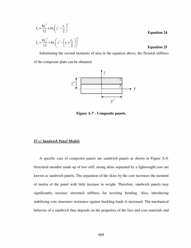
668
2
1*
1
3
11
212
−+=
tzbt
btI
Equation 24
2
21
*
2
3
22
212
+−+=
ttzbt
btI
Equation 25
Substituting the second moments of area in the equation above, the flexural stiffness
of the composite plate can be obtained.
z
yz*
y*
1
2
Figure A-7 - Composite panels.
IV c) Sandwich Panel Models
A specific case of composite panels are sandwich panels as shown in Figure A-8.
Structural member made up of two stiff, strong skins separated by a lightweight core are
known as sandwich panels. The separation of the skins by the core increases the moment
of inertia of the panel with little increase in weight. Therefore, sandwich panels may
significantly increase structural stiffness for resisting bending. Also, introducing
stabilizing core structures resistance against buckling loads is increased. The mechanical
behavior of a sandwich thus depends on the properties of the face and core materials and
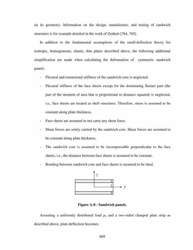
669
on its geometry. Information on the design, manufacture, and testing of sandwich
structures is for example detailed in the work of Zenkert [764, 765].
In addition to the fundamental assumptions of the small-deflection theory for
isotropic, homogeneous, elastic, thin plates described above, the following additional
simplification are made when calculating the deformation of symmetric sandwich
panels:
- Flexural and extensional stiffness of the sandwich core is neglected.
- Flexural stiffness of the face sheets except for the dominating Steiner part (the
part of the moment of area that is proportional to distance squared) is neglected,
i.e., face sheets are treated as shell structures. Therefore, stress is assumed to be
constant along plate thickness.
- Face sheets are assumed to not carry any shear force.
- Shear forces are solely carried by the sandwich core. Shear forces are assumed to
be constant along plate thickness.
- The sandwich core is assumed to be incompressible perpendicular to the face
sheets, i.e., the distance between face sheets is assumed to be constant.
- Bonding between sandwich core and face sheets is assumed to be ideal.
z
1
2
3
y
Figure A-8 - Sandwich panels.
Assuming a uniformly distributed load p0 and a two-sided clamped plate strip as
described above, plate deflection becomes:
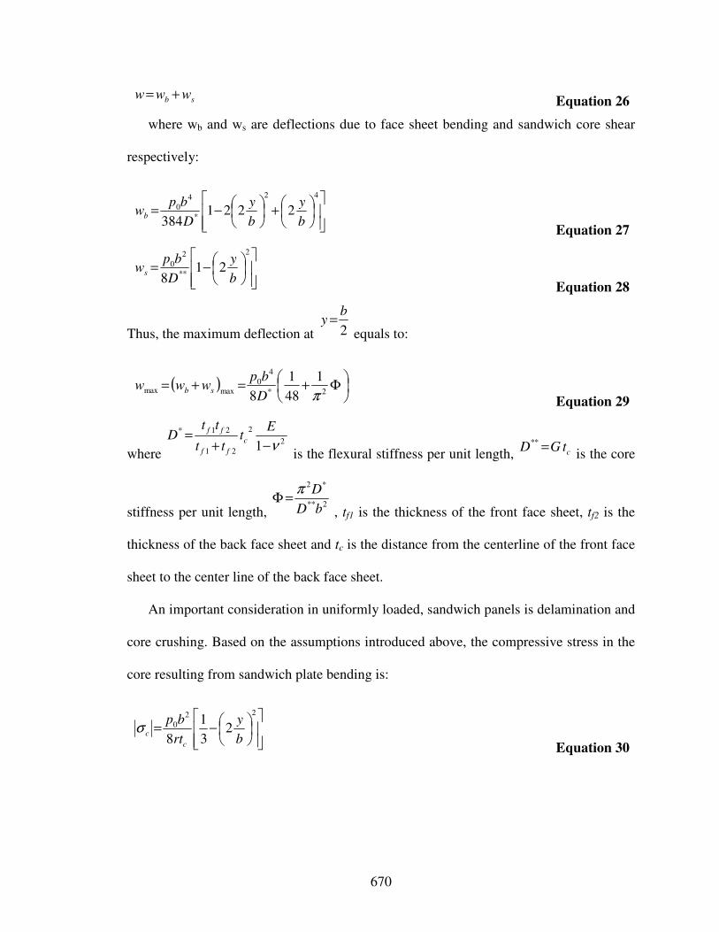
670
sb www +=
Equation 26
where wb and ws are deflections due to face sheet bending and sandwich core shear
respectively:
+
−=
42
*
4
0 2221384 b
y
b
y
D
bpwb
Equation 27
−=
2
**
2
0 218 b
y
D
bpws
Equation 28
Thus, the maximum deflection at
2
by =
equals to:
( )
Φ+=+=
2*
4
0maxmax
1
48
1
8 πD
bpwww sb
Equation 29
where
2
2
21
21*
1 ν−+=
Et
tt
ttD c
ff
ff
is the flexural stiffness per unit length,
ctGD =**
is the core
stiffness per unit length,
2**
*2
bD
Dπ=Φ
, tf1 is the thickness of the front face sheet, tf2 is the
thickness of the back face sheet and tc is the distance from the centerline of the front face
sheet to the center line of the back face sheet.
An important consideration in uniformly loaded, sandwich panels is delamination and
core crushing. Based on the assumptions introduced above, the compressive stress in the
core resulting from sandwich plate bending is:
−=
22
0 23
1
8 b
y
rt
bp
c
cσ
Equation 30
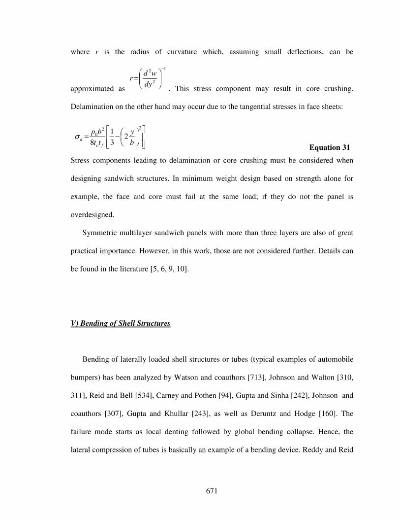
671
where r is the radius of curvature which, assuming small deflections, can be
approximated as
1
2
2−
=
dy
wdr
. This stress component may result in core crushing.
Delamination on the other hand may occur due to the tangential stresses in face sheets:
−=
22
0 23
1
8 b
y
tt
bp
fc
dσ
Equation 31
Stress components leading to delamination or core crushing must be considered when
designing sandwich structures. In minimum weight design based on strength alone for
example, the face and core must fail at the same load; if they do not the panel is
overdesigned.
Symmetric multilayer sandwich panels with more than three layers are also of great
practical importance. However, in this work, those are not considered further. Details can
be found in the literature [5, 6, 9, 10].
V) Bending of Shell Structures
Bending of laterally loaded shell structures or tubes (typical examples of automobile
bumpers) has been analyzed by Watson and coauthors [713], Johnson and Walton [310,
311], Reid and Bell [534], Carney and Pothen [94], Gupta and Sinha [242], Johnson and
coauthors [307], Gupta and Khullar [243], as well as Deruntz and Hodge [160]. The
failure mode starts as local denting followed by global bending collapse. Hence, the
lateral compression of tubes is basically an example of a bending device. Reddy and Reid
672
[528] report that the energy absorbed when laterally compressing tubes with side
constraints is three times more than that of a free system. However, Johnson and Reid
[309] observed that “energy absorbed by a laterally loaded tube is one order of magnitude
less than the axially loaded one”.
For example, assuming a tube of length L, diameter D and thickness t (with D >> t)
has stroke of approximately 0.7D in lateral compression and 0.7L in axial compression,
the axial buckling mode has a specific energy absorption capacity which is approximately
10 times that of the same tube when compressed laterally between flat plates [539].
Moreover, a tube in axial loading can be ensured that all of its material participates in the
absorption of energy by plastic work.
Derived from laterally loaded tubes, many researchers studied energy dissipation in
loaded rings. For example, Reid and coauthors [535, 538], Reid and Reddy [537], Sugita
[641] as well as Reddy and coauthors [532] have studied the crushing of various metal
ring systems. Laterally loaded square rings have been investigated by Sinha and Chitkara
[608]. When loaded in a direction parallel to two of the sides, the large deformation
mechanism is preceded by a buckling phase. The circumferential stresses generated by
the change in shape of the cross section effectively constrain the usual ring-type collapse
mode of the cross section leading to modes of deformation which can absorb up to eight
or nine times the amount of energy absorbed by an equal length of tube under lateral
compressions. This however is usually still less than the amount of energy absorbed by a
tube under axial compression.
673
VI) Inversion of Structures
Axially loaded thin metallic tubes may also dissipate energy in other modes of
deformation than bending, including inversion and splitting. Tube inversion involves the
turning inside or outside in of a thin circular tube made of ductile material. Tube
inversion provides perhaps the simplest example of a deformation field ominated by a
toroidal deformation zone (knuckle region) and bounded by plastic hinges within which
membrane (circumferential) stretching occurs. The main advantage of this mode of
deformation is the constant inversion load that can be obtained for a uniform tube.
Characteristics of tube inversion have been investigated by Kinkead [325], Chirwa
[125], Calladine [86], and Reid [539, 541]. Chirwa showed that the inversion of tapered
thin-walled tubes leads to a 50% increase in absorbed energy when compared to uniform
thickness tube inversion. However, tube inversion is limited by die radius. If the radius is
small, progressive buckling of the tube will result. If the radius is larger than some
limiting value, tub splitting occurs. In general, practical shortcomings, such as difficulties
in securing axial loading, have directed attention to other devices [309].
However, DeOlieveira and Wierzbicki [159] as well as Gupta [244] and coauthors
have analyzed the inversion of spherical shells. The mechanism is somewhat similar to
the tube inversion mechanism, material passing into the central dimple region through a
circular knuckle whose radius increases with deformation and, as such, is an efficient
method of energy absorption. The deformation modes followed are usually elastic
flattening of the crown with the generation of in-plane compressive radial stresses which
674
at some point lead to axisymmetric elastic or plastic dimpling or snap-through. Further
increase in load usually generates three, four or more plastic lobes.
VII) Splitting (Fracture) of Structures
As stated above, axially loaded thin metallic tubes may also dissipate energy in other
modes of deformation than bending, including inversion and splitting. Tube splitting is a
special case of tube inversion where the die radius is large enough to cause splitting
instead of inversion. Ezra and Fay [194] have identified the combined modes of axial
splitting and subsequent curling of the split ends of the tubes as efficient means of energy
dissipation. Energy is dissipated in tearing of the metal of the tube into strips. Tube
splitting has been further investigated by Stronge and coauthors [638], Reddy and Reid
[529], Atkins [30], as well as Lu and coauthors [378]. However, practical shortcomings,
such as the ones for tube inversion, have directed attention to other devices [309].
VIII) Flattening (Progressive Buckling or Crushing) of Axially Loaded Tubes and
Frustra
VIII a) Open-Top Tubes and Frustra
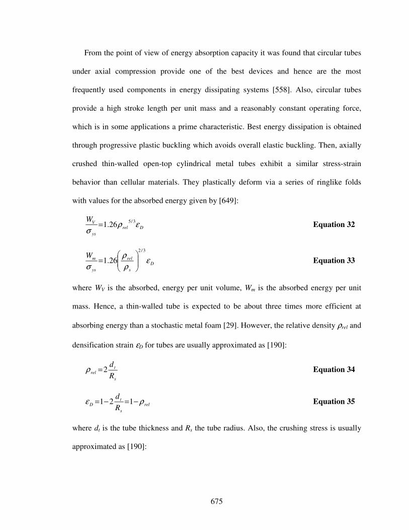
675
From the point of view of energy absorption capacity it was found that circular tubes
under axial compression provide one of the best devices and hence are the most
frequently used components in energy dissipating systems [558]. Also, circular tubes
provide a high stroke length per unit mass and a reasonably constant operating force,
which is in some applications a prime characteristic. Best energy dissipation is obtained
through progressive plastic buckling which avoids overall elastic buckling. Then, axially
crushed thin-walled open-top cylindrical metal tubes exhibit a similar stress-strain
behavior than cellular materials. They plastically deform via a series of ringlike folds
with values for the absorbed energy given by [649]:
Drel
ys
VWερ
σ
3/526.1= Equation 32
D
s
rel
ys
mWε
ρ
ρ
σ
3/2
26.1
= Equation 33
where WV is the absorbed, energy per unit volume, Wm is the absorbed energy per unit
mass. Hence, a thin-walled tube is expected to be about three times more efficient at
absorbing energy than a stochastic metal foam [29]. However, the relative density ρrel and
densification strain εD for tubes are usually approximated as [190]:
s
trel
R
d2=ρ Equation 34
rel
s
tD
R
dρε −=−= 121 Equation 35
where dt is the tube thickness and Rs the tube radius. Also, the crushing stress is usually
approximated as [190]:
676
3/5
26.1 rel
ys
ρσ
σ= Equation 36
The behavior of thin-walled tubes with circular or square cross-sections when
subjected to axial loads has been studied by Pugsley and Macaulay [517], Johnson and
coauthors [308], Andrew and coauthors [23], Tvergaard [677], as well as Mamalis and
Johnson [395]. Mamalis and coauthors [389, 392, 394] then analyzed different materials
including steel, aluminum, PVC, aluminum and bi-material tubes. Besides simple
cylindrical tubes, Mamalis and coauthors [393] study energy dissipation and associated
failure modes when axially loading polygonal thin-walled cylinders. Also, Wierzbicki
and Abramowicz [7, 8, 725] analyze the crushing of thin-walled multicorner structures
made from plate elements, by considering stationary plastic hinges and narrow toroidal
regions of circumferential stretching and bending traveling through structure.
Furthermore, Wierzbicki and coauthors [726] introduce a S-shape folding element.
Moreover, corrugated tubes were analyzed by Singace and El-Sobky [605]. Also, it was
demonstrated that the insertion of diametrical tension stiffeners [312] or axial stiffeners
[62] significantly affects the tube load deformation behavior and result in stiffness
properties which are directionally sensitive.
Foam-filled circular or square tubes under axial crushing were investigated by many
researchers including Reid and coauthors [540], Abramowicz and Wierzbicki [6] and
Reddy and Wall [531]. An important point to note is that the increase in energy
absorption capacity is greater than the energy required to crush the foam filling. The
presence of the foam produces changes in the deformation field of the wall: the buckling
length is reduced, and the extent to which the fold mechanism can be crushed is
modified, both of which affect the level of the mean crushing load. Budiansky [81]
677
compares minimum weights of columns having solid square or circular cross-sections
with those of similar metal-foam-filled tubes, hollow tubes and tubes whose walls are
foam-core sandwiches. In this study, hollow circular turn out to have be more weight
efficient than hollow square tubes, foam-filled square tubes and square tubes whose walls
are foam-core sandwiches. Only for long or lightly loaded columns, circular tubes whose
walls are foam-core sandwiches are more weight sufficient than hollow circular tubes.
Also, in structures of conventional scales, such hypothetical designs tend to be
impractical. Hence, in this work, only hollow circular tubes are analyzed.
However, axial crushing of filled tubes (or honeycombs) is focus of current research.
For example, axial crushing of wood-filled square metal tubes was investigated by Reddy
and Al-Hassani [533]. Filling with crushable material (sand) is a way of mobilizing
membrane stresses at large deformations.
The occurrence of frusta as structural members has drawn some attention, especially
due to their stable plastic behavior when crushed axially. Mamalis and coauthors [390,
391] report that the collapse of axially loaded conical shells and frustra is by a variety of
plastic folding mechanisms (axisymmetric rings for thick frustra or diamond patterns for
thin frustra) which resemble the collapse mechanisms of thin walled cylindrical shells.
They observed that both the peak and post-buckling load as well as the plastic energy
dissipated (i) increases in a parabolic manner with increases in wall thickness and (ii)
decreases with an increase in semi-apical angle. Also, they proposed an extensible
theoretical model to predict the plastically dissipated energy and the mean post-buckling
load for axially crumpled thin walled circular cones and frustra based on a consideration
678
of the plastic work dissipated in plastic hinges and in stretching of material between them
without considering their interaction [391].
The collapse load and energy absorbing capacity of single tubular components can be
increased by using tensile bracing members, which lead to the formation of greater
number of plastic hinges. Energy dissipation of braced metal tubes has been studied by
Johnson and coauthors [307], Reid and coauthors [536], Carney and Veillette [93], Reddy
and coauthors [530], Wu and Carney [738], as well as Carney and Pothen [94].
VIII b) Closed-Top Tubes and Frustra
The compressive deformation behavior of tubes and conical frustra with closed-tops
in particular has been investigated by Deshpande and Fleck [164]. They note that closed-
top frustra deform by a traveling hinge mode of deformation provided material tearing
and elastic buckling is avoided. However, one particular instantiation of axially loaded
closed-top tubes and frustra is referred to as egg-box material.
Egg-box materials’ geometry can be approximated by a square array of conical frustra
with each frustum of half the height of the egg-box material; the base diameter of the
frustum is taken as the spacing between adjacent crowns of the egg-box. The primary
mode of collapse is by traveling plastic hinge within each periodic cell of the egg-box
[164]. The same collapse mode is exhibited by a closed-top concial frustum. In particular,
the collapse of egg-box material under constrained compression is by (i) a traveling
plastic hinge mechanism, (ii) elastic buckling or (iii) tearing. According to Deshpande
and Fleck [164] the maximum energy absorption is achieved along the boundary between
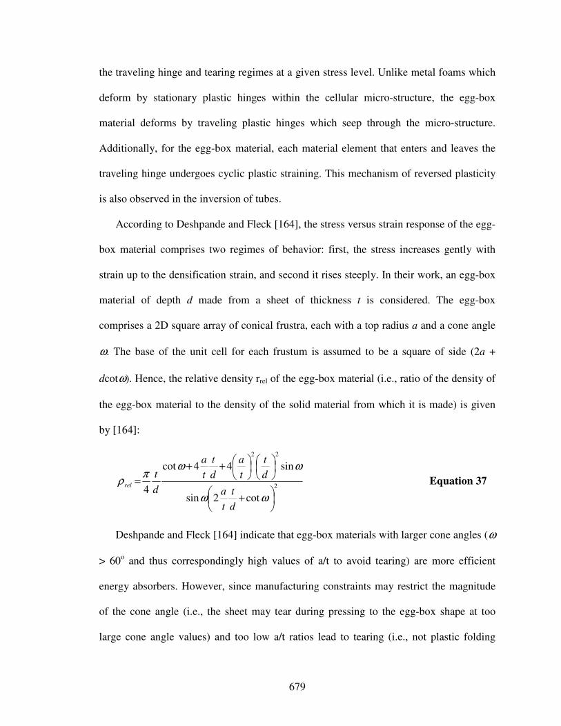
679
the traveling hinge and tearing regimes at a given stress level. Unlike metal foams which
deform by stationary plastic hinges within the cellular micro-structure, the egg-box
material deforms by traveling plastic hinges which seep through the micro-structure.
Additionally, for the egg-box material, each material element that enters and leaves the
traveling hinge undergoes cyclic plastic straining. This mechanism of reversed plasticity
is also observed in the inversion of tubes.
According to Deshpande and Fleck [164], the stress versus strain response of the egg-
box material comprises two regimes of behavior: first, the stress increases gently with
strain up to the densification strain, and second it rises steeply. In their work, an egg-box
material of depth d made from a sheet of thickness t is considered. The egg-box
comprises a 2D square array of conical frustra, each with a top radius a and a cone angle
ω. The base of the unit cell for each frustum is assumed to be a square of side (2a +
dcotω). Hence, the relative density rrel of the egg-box material (i.e., ratio of the density of
the egg-box material to the density of the solid material from which it is made) is given
by [164]:
2
22
cot2sin
sin44cot
4
+
++
=
ωω
ωωπ
ρ
d
t
t
a
d
t
t
a
d
t
t
a
d
trel Equation 37
Deshpande and Fleck [164] indicate that egg-box materials with larger cone angles (ω
> 60o and thus correspondingly high values of a/t to avoid tearing) are more efficient
energy absorbers. However, since manufacturing constraints may restrict the magnitude
of the cone angle (i.e., the sheet may tear during pressing to the egg-box shape at too
large cone angle values) and too low a/t ratios lead to tearing (i.e., not plastic folding
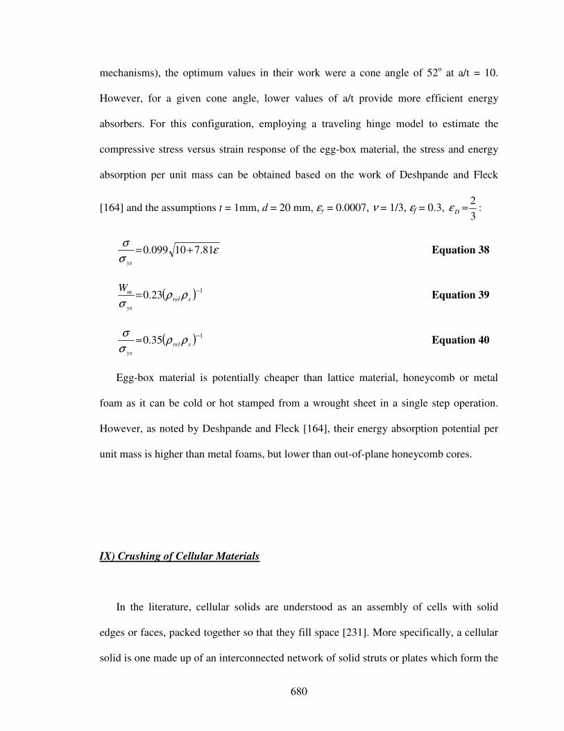
680
mechanisms), the optimum values in their work were a cone angle of 52o at a/t = 10.
However, for a given cone angle, lower values of a/t provide more efficient energy
absorbers. For this configuration, employing a traveling hinge model to estimate the
compressive stress versus strain response of the egg-box material, the stress and energy
absorption per unit mass can be obtained based on the work of Deshpande and Fleck
[164] and the assumptions t = 1mm, d = 20 mm, εy = 0.0007, ν = 1/3, εf = 0.3, 3
2≈Dε :
εσ
σ81.710099.0 +=
ys
Equation 38
( ) 123.0
−= srel
ys
mWρρ
σ Equation 39
( ) 135.0
−≈ srel
ys
ρρσ
σ Equation 40
Egg-box material is potentially cheaper than lattice material, honeycomb or metal
foam as it can be cold or hot stamped from a wrought sheet in a single step operation.
However, as noted by Deshpande and Fleck [164], their energy absorption potential per
unit mass is higher than metal foams, but lower than out-of-plane honeycomb cores.
IX) Crushing of Cellular Materials
In the literature, cellular solids are understood as an assembly of cells with solid
edges or faces, packed together so that they fill space [231]. More specifically, a cellular
solid is one made up of an interconnected network of solid struts or plates which form the
681
edges and faces of cells. Examples of such materials are common in nature, e.g., wood,
cork, sponge, cancellous bone, coral etc. Common man-made examples of cellular solids
are three-dimensional foams with open or closed cells as well as in- or out-of-plane
honeycombs. However, the stress/strain response exhibited by low relative density
cellular metals establishes two aspects of their engineering utility: (i) their relatively high
stiffness and yield strength achievable at low density creates an opportunity for ultralight
structures, with integrally bonded dense face sheets, and (ii) large compressive strains
achievable at nominally constant stress (before the material compacts) impart a high
energy absorption capacity at force levels relevant to crash and blast amelioration
systems. Hence, crushing of cellular materials, i.e., foams and honeycombs in particular,
is among the most promising energy absorption mechanisms.
Often the benefits of cellular metal system derive from an acceptable structural
performance combined with lower costs or greater durability than competing concepts.
Also, cellular materials appear to possess useful combinations of thermophysical and
mechanical properties that can be tailored by adjusting the relative density, cellular
architecture or material type [649]. Hence, cellular materials are well-suited for
multifunctional materials design in the structural, thermal or electromagnetic domain. For
example, the volume fraction of material in unit cells is relatively low, which allows the
effective permittivity of the material also to be low and hence makes cellular materials
well suited for applications where enhance electromagnetic and structural properties are
required simultaneously [612]. However, they are particularly well suited when load
support and simultaneously mechanical impact/blast absorption is required. They have
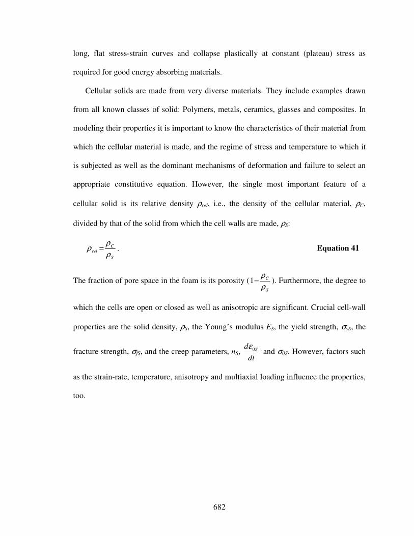
682
long, flat stress-strain curves and collapse plastically at constant (plateau) stress as
required for good energy absorbing materials.
Cellular solids are made from very diverse materials. They include examples drawn
from all known classes of solid: Polymers, metals, ceramics, glasses and composites. In
modeling their properties it is important to know the characteristics of their material from
which the cellular material is made, and the regime of stress and temperature to which it
is subjected as well as the dominant mechanisms of deformation and failure to select an
appropriate constitutive equation. However, the single most important feature of a
cellular solid is its relative density ρrel, i.e., the density of the cellular material, ρC,
divided by that of the solid from which the cell walls are made, ρS:
S
Crel
ρ
ρρ = . Equation 41
The fraction of pore space in the foam is its porosity (S
C
ρ
ρ−1 ). Furthermore, the degree to
which the cells are open or closed as well as anisotropic are significant. Crucial cell-wall
properties are the solid density, ρS, the Young’s modulus ES, the yield strength, σyS, the
fracture strength, σfS, and the creep parameters, nS, dt
d S0ε and σ0S. However, factors such
as the strain-rate, temperature, anisotropy and multiaxial loading influence the properties,
too.
683
IX a) Foams
In general, polyhedral cells which pack in three dimensions to fill space are referred
to as three-dimensional cellular materials foams [231]. Foams are random cellular solids
with a highly imperfect microstructure. Techniques today exist for foaming almost any
material, such as polymers, metals, ceramics, glasses, composites, etc. However, if the
solid of which the foam is made is contained in the cell edges only so that the cells
connect through open faces, the foam is said to be open-celled. If the faces are solid too,
so that each cell is sealed off from its neighbors, it is said to be closed-celled. Also, some
foams are partly open-celled and partly closed-celled.
The unit cells which pack to fill a plane can be isotropic or anisotropic with different
shapes. Even if the cell shape is fixed. The cells can be stacked in more than one way
giving structures which have differing edge connectivity and different properties. Most
foams are not regular packings of identical units but contain cells of different sizes and
shapes with differing numbers of faces and edges. But, even the most random of foams
obey topological rules, such as Euler’s law, Aboav-Weaire law and Lewis’s riule,
summarized by Gibson and Ashby [231].
Foaming dramatically extends the range of properties available to the engineer.
Foams are well suited for insulation, cushioning and absorbing kinetic energy form
impacts. The strength of a foam can be adjusted over a wide range by controlling its
relative density. Special ultra-low-density foams can be made with a relative density as
low as 0.001. Polymeric foams used for cushioning, packaging and insulation have
relative densities which are usually between 0.05 and 0.2. As the relative density
684
increases, the cell walls thicken and the pore space shrinks. Above about 0.3 there is a
transition from a cellular structures to one which is better thought of as a solid containing
isolated pores.
The low densities permit the design of light, stiff components such as sandwich
panels and large portable structures, and of flotation of all sorts. The low thermal
conductivity of foams allows cheap, reliable thermal insulation. When fire hazard is a
major consideration or when a very long life is envisaged, glass foams can be used. The
low strengths and large compressive strains (0.7 or more) at almost constant stress make
foams attractive for energy-absorbing applications.
Foam-cored sandwich panels compete with stringer-reinforced plates, particularly in
curved configurations [29]. Economies of processing and fabrication give foam-cored
sandwich panels cost advantages in many applications, compared to the difficult and
costly process of assembling a sandwich shell by joining precurved face sheets and core.
Several of the cellular material foam manufacturing methods enable shape flexibility, i.e.,
hollow thin-walled configuration with arbitrary geometry to be filled with cellular
material. This process provided a light/stiff system with broad-ranging geometric
complexity that cannot be duplicated using either honeycomb cores sandwich panels or
stiffened plates [190].
Furthermore, benefits with respect to multiple use give integrally formed metal foam
cores thermal and acoustic advantages over conventional panel structures. For example, a
trend toward higher heat dissipation is established as either the ligament diameter
becomes smaller or the relative density increases (this trend reflects the higher internal
surface area as the ligament diameter decreases and the greater heat conduction cross-
685
section as the relative density increases). Moreover, stiffness at low weight leads to
increases in the natural frequency of vibration and hence noise suppression. Also, the
imperfection-sensitivity of thin-walled columns and stiffened panels tends to make
failures catastrophic when they occur, whereas foam-core columns and sandwich panels
can be expected to undergo more graceful collapse. Also, face-sheets can be integrally
formed with a closed cell metal foam core producing sandwiches without the usual
environmental and delamination susceptibilities of honeycomb sandwiches.
Also, closed-cell foams have the lowest thermal conductivity of any conventional
non-vacuum insulation [29]. The thermal conductivity of a foam can be thought of as
having four contributions: conduction through the solid, conduction through the gas,
convection within the cells and radiation through the cells walls and across the cell voids.
Several factors combine to limit heat flow in foams: the low volume fraction of the solid
phase; the small cell size which virtually suppresses convection and reduces radiation
through repeated absorption and reflection at the cell walls, and the poor conductivity of
the enclosed gas. The specific heat per unit volume, too, is low for foams, making them
especially attractive for structures with a low thermal mass. The coefficient of thermal
expansion of most foams is roughly the same as that of the solid from which they are
made. Also, the melting or softening point of a foam is the same as that of the solid from
which it is made.
However, Budiansky [81] has found that flat sandwich panels with metal foam cores
generally do not have a potential weight advantage over their axially stiffened
counterparts for the case of uniaxial loads. But, according to Hutchinson and He [285],
the biaxial stiffness of metal foam cores do contribute to load carrying capacity in most
686
shell buckling problems. Thus, there is an important range of loads for which sandwich
construction employing cores of metal foam have a distinct weight advantage over the
lightest weight metal stringer construction.
As described above, in many cases, “optimal” energy dissipation characteristics
require the absorption of energy whilst keeping the peak force (or acceleration or
deceleration) below a certain limit (to avoid damage or injury). Foams are especially
good at this, since for the same energy absorption capacity as the solid from which they
are made, foams always generate lower peak forces. Energy is absorbed as the cell walls
yield plastically, collapse by elastic buckling or brittle crushing (depending on the
material of which it is made). The compressive stress-strain curve for foams usually
shows linear elasticity at low stresses, followed by a long collapse plateau, truncated by a
regime of densification in which the stress rises steeply.
Linear elasticity is controlled by cell wall bending and, if the cells are closed, by cell
face stretching. The plateau stress is associated with collapse of the cells – by elastic
buckling in elastomeric foams, by the formation of plastic hinges in a foam which yields,
and by brittle crushing in a brittle foam. When the cells have almost completely collapsed
opposing cell walls touch (crush together) and further strain compresses the solid (cell
wall material) itself, giving the final region of rapidly increasing stress. In this final
region, the stress-strain curve rises steeply, tending to a slope of ES (though this is so
much larger than EC that the stress-strain curve looks vertical) at a limiting densification
strain εD, according to Gibson and Ashby [231], of:
−=
s
Dρ
ρε 4.11
687
Some of the mechanisms at work in absorbing energy are related to the elastic, plastic or
brittle deformation of the cell walls, others, to the compression or flow of the fluid within
the cells. The relevant mechanisms for a particular foam depend on the behavior of the
cell wall material and on whether or not the cells are open or closed.
Linear elasticity is limited to small strains, typically 5% or less. Elastomeric foams
can be stretched or compressed to much larger strains than this. The deformation at the
elastic collapse stress is still recoverable (and thus elastic) but it is non-linear. Elastic
collapse in foams (like in honeycombs) is caused by the elastic buckling of cell walls.
The elastic collapse stress and the post-collapse behavior depend on whether the foam
has open or closed cells.
Foams made from materials which have a plastic yield point (such as rigid polymers,
or metals) collapse plastically when loaded beyond the linear-elastic regime. Plastic
collapse, like elastic buckling, gives a long horizontal plateau to the stress-strain curve,
though the strain is no longer recoverable. This is exploited in foams for crash protection
and energy-absorbing systems. Plastic and brittle foams dissipate work done in the
plateau region completely as plastic work, or as work of fracture, or in friction between
broken fragments of cell walls.
Brittle foams (ceramics, glasses and some brittle polymers) collapse by brittle
crushing. For example, the low crushing strength of glass and polymer foams can be a
problem when they are used as insulation which must also support load.
In deforming composite foams, where cell wall materials are themselves composites,
a great deal of energy is dissipated by pulling out and unraveling fibers in complicated
688
ways. However, the understanding of these mechanisms is still incomplete, but an area
with scope for further exploitation.
The linear-elastic behavior of a foam is characterized by a set of moduli. Two moduli
are needed to describe an isotropic foam. They are usually chosen from the Young’s
modulus EF, the shear modulus GF and Poisson’s ratio νF. However, if the structure is
axisymmetric, five moduli are required. If it is orthotropic, nine moduli are required.
In summary: Open-cell foams and the current generation of commercially produced
closed-cell metal foams absorb energy primarily by the bending of the cell edges at
stationary plastic hinges (since the connectivity of neighboring cell edges is sufficiently
small). Fluctuations in the macroscopic stress versus strain curve are observed. The cause
is the successive collapse of layers of the foam. Numerous studies on isotropic open-cell
foams have shown that both the stiffness and strength of the foams are governed by cell
wall bending for all loading conditions, where stiffness scales as 1*ρrel2 and strength
scales as 0.4*ρrel1.5, where ρrel the relative density [29, 161, 190, 232]. Most isotropic
closed-cell foams also follow these scaling laws, as the cell faces, which carry membrane
stresses, buckle or rupture at stresses so low due to imperfections (such as curved and
wrinkled cell walls, thin or missing walls and high relative density domains or inclusions)
that their contribution to stiffness and strength is small, leaving the cell edges to carry
most of the load. Ideally, i.e., for closed cellular structures with straight walls and borders
with uniform thickness, stiffness scales as 0.33*ρrel and strength scales as 0.3*ρrel, where
ρrel the relative density for isotropic closed-cell foams [190].
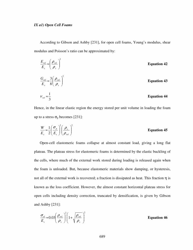
689
IX a1) Open Cell Foams
According to Gibson and Ashby [231], for open cell foams, Young’s modulus, shear
modulus and Poisson’s ratio can be approximated by:
2
≈
s
rel
s
rel
E
E
ρ
ρ Equation 42
2
8
3
≈
s
rel
s
rel
E
G
ρ
ρ Equation 43
3
1≈relν Equation 44
Hence, in the linear elastic region the energy stored per unit volume in loading the foam
up to a stress σp becomes [231]:
22
2
1
≈
rel
s
s
p
s EE
W
ρ
ρσ Equation 45
Open-cell elastomeric foams collapse at almost constant load, giving a long flat
plateau. The plateau stress for elastomeric foams is determined by the elastic buckling of
the cells, where much of the external work stored during loading is released again when
the foam is unloaded. But, because elastomeric materials show damping, or hysteresis,
not all of the external work is recovered; a fraction is dissipated as heat. This fraction η is
known as the loss coefficient. However, the almost constant horizontal plateau stress for
open cells including density correction, truncated by densification, is given by Gibson
and Ashby [231]:
22
103.0
+
≈
s
rel
s
rel
s
el
E ρ
ρ
ρ
ρσ Equation 46
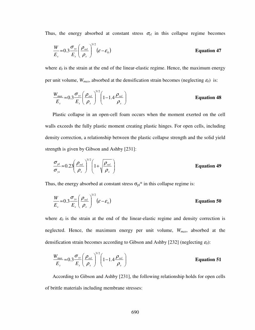
690
Thus, the energy absorbed at constant stress σel in this collapse regime becomes
( )0
2/3
3.0 εερ
ρσ−
≈
s
rel
s
ys
s EE
W Equation 47
where ε0 is the strain at the end of the linear-elastic regime. Hence, the maximum energy
per unit volume, Wmax, absorbed at the densification strain becomes (neglecting ε0) is:
−
≈
s
rel
s
rel
s
ys
s EE
W
ρ
ρ
ρ
ρσ4.113.0
2/3
max Equation 48
Plastic collapse in an open-cell foam occurs when the moment exerted on the cell
walls exceeds the fully plastic moment creating plastic hinges. For open cells, including
density correction, a relationship between the plastic collapse strength and the solid yield
strength is given by Gibson and Ashby [231]:
+
≈
s
rel
s
rel
ys
pl
ρ
ρ
ρ
ρ
σ
σ123.0
2/3
Equation 49
Thus, the energy absorbed at constant stress σpl* in this collapse regime is:
( )0
2/3
3.0 εερ
ρσ−
≈
s
rel
s
ys
s EE
W Equation 50
where ε0 is the strain at the end of the linear-elastic regime and density correction is
neglected. Hence, the maximum energy per unit volume, Wmax, absorbed at the
densification strain becomes according to Gibson and Ashby [232] (neglecting ε0):
−
≈
s
rel
s
rel
s
ys
s EE
W
ρ
ρ
ρ
ρσ4.113.0
2/3
max Equation 51
According to Gibson and Ashby [231], the following relationship holds for open cells
of brittle materials including membrane stresses:
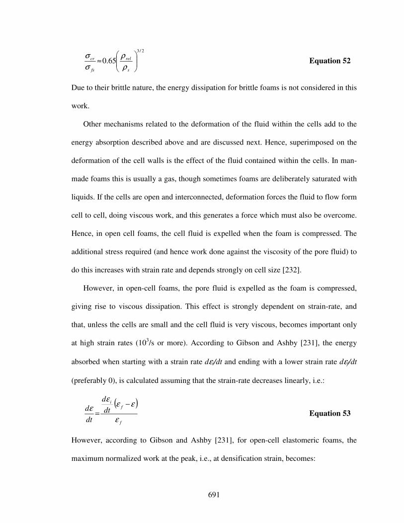
691
2/3
65.0
≈
s
rel
fs
cr
ρ
ρ
σ
σ Equation 52
Due to their brittle nature, the energy dissipation for brittle foams is not considered in this
work.
Other mechanisms related to the deformation of the fluid within the cells add to the
energy absorption described above and are discussed next. Hence, superimposed on the
deformation of the cell walls is the effect of the fluid contained within the cells. In man-
made foams this is usually a gas, though sometimes foams are deliberately saturated with
liquids. If the cells are open and interconnected, deformation forces the fluid to flow form
cell to cell, doing viscous work, and this generates a force which must also be overcome.
Hence, in open cell foams, the cell fluid is expelled when the foam is compressed. The
additional stress required (and hence work done against the viscosity of the pore fluid) to
do this increases with strain rate and depends strongly on cell size [232].
However, in open-cell foams, the pore fluid is expelled as the foam is compressed,
giving rise to viscous dissipation. This effect is strongly dependent on strain-rate, and
that, unless the cells are small and the cell fluid is very viscous, becomes important only
at high strain rates (103/s or more). According to Gibson and Ashby [231], the energy
absorbed when starting with a strain rate dεi/dt and ending with a lower strain rate dεf/dt
(preferably 0), is calculated assuming that the strain-rate decreases linearly, i.e.:
( )
f
fi
dt
d
dt
d
ε
εεε
ε−
= Equation 53
However, according to Gibson and Ashby [231], for open-cell elastomeric foams, the
maximum normalized work at the peak, i.e., at densification strain, becomes:
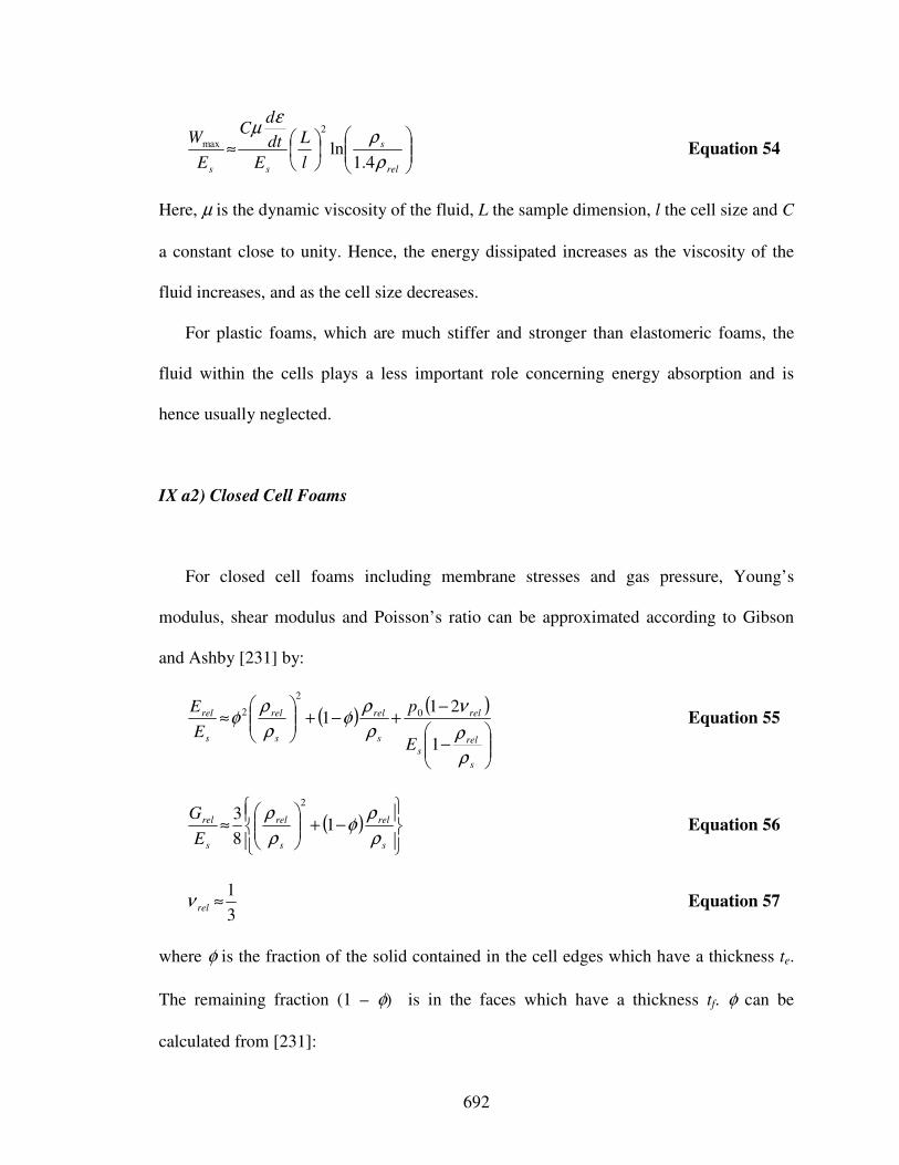
692
≈
rel
s
ss l
L
E
dt
dC
E
W
ρ
ρε
µ
4.1ln
2
max Equation 54
Here, µ is the dynamic viscosity of the fluid, L the sample dimension, l the cell size and C
a constant close to unity. Hence, the energy dissipated increases as the viscosity of the
fluid increases, and as the cell size decreases.
For plastic foams, which are much stiffer and stronger than elastomeric foams, the
fluid within the cells plays a less important role concerning energy absorption and is
hence usually neglected.
IX a2) Closed Cell Foams
For closed cell foams including membrane stresses and gas pressure, Young’s
modulus, shear modulus and Poisson’s ratio can be approximated according to Gibson
and Ashby [231] by:
( )( )
−
−+−+
≈
s
rels
rel
s
rel
s
rel
s
rel
E
p
E
E
ρ
ρ
ν
ρ
ρφ
ρ
ρφ
1
211 0
2
2 Equation 55
( )
−+
≈
s
rel
s
rel
s
rel
E
G
ρ
ρφ
ρ
ρ1
8
32
Equation 56
3
1≈relν Equation 57
where φ is the fraction of the solid contained in the cell edges which have a thickness te.
The remaining fraction (1 – φ) is in the faces which have a thickness tf. φ can be
calculated from [231]:
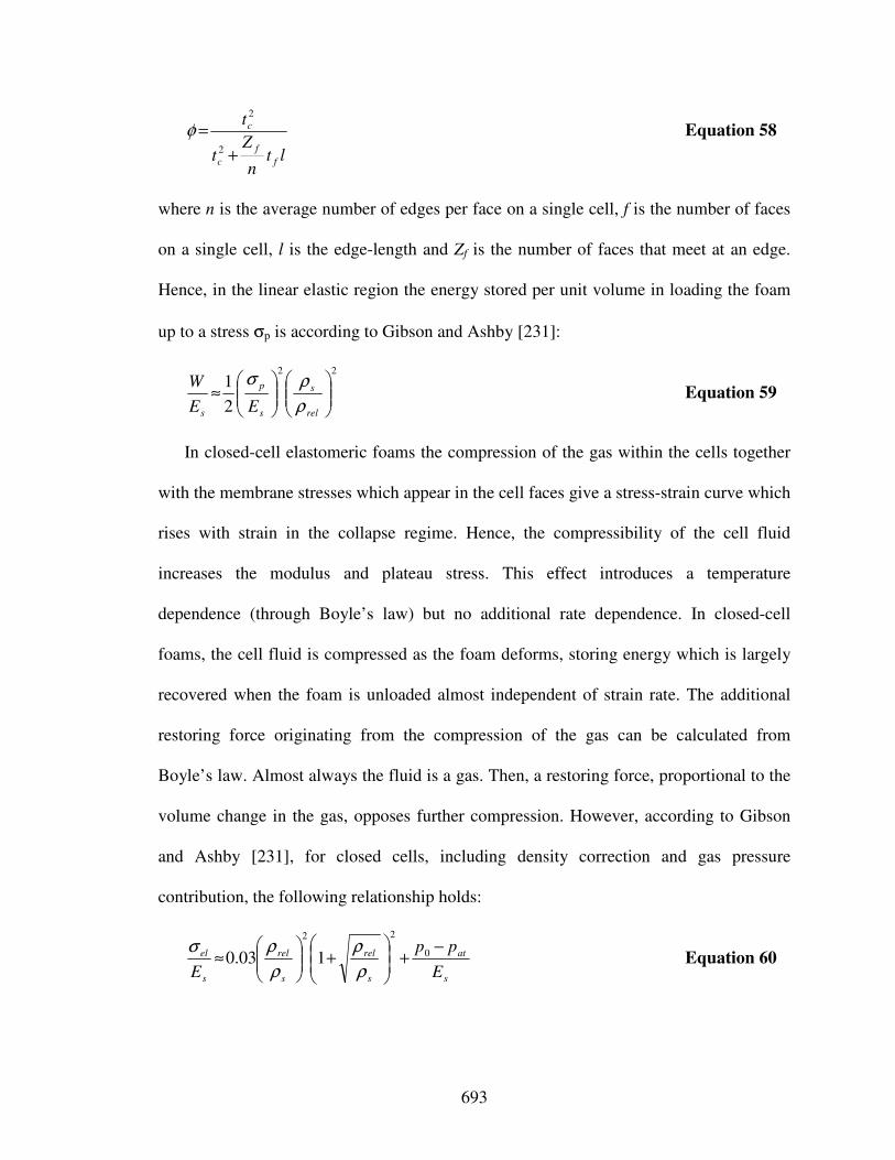
693
ltn
Zt
t
f
f
c
c
+
=2
2
φ Equation 58
where n is the average number of edges per face on a single cell, f is the number of faces
on a single cell, l is the edge-length and Zf is the number of faces that meet at an edge.
Hence, in the linear elastic region the energy stored per unit volume in loading the foam
up to a stress σp is according to Gibson and Ashby [231]:
22
2
1
≈
rel
s
s
p
s EE
W
ρ
ρσ Equation 59
In closed-cell elastomeric foams the compression of the gas within the cells together
with the membrane stresses which appear in the cell faces give a stress-strain curve which
rises with strain in the collapse regime. Hence, the compressibility of the cell fluid
increases the modulus and plateau stress. This effect introduces a temperature
dependence (through Boyle’s law) but no additional rate dependence. In closed-cell
foams, the cell fluid is compressed as the foam deforms, storing energy which is largely
recovered when the foam is unloaded almost independent of strain rate. The additional
restoring force originating from the compression of the gas can be calculated from
Boyle’s law. Almost always the fluid is a gas. Then, a restoring force, proportional to the
volume change in the gas, opposes further compression. However, according to Gibson
and Ashby [231], for closed cells, including density correction and gas pressure
contribution, the following relationship holds:
s
at
s
rel
s
rel
s
el
E
pp
E
−+
+
≈ 0
22
103.0ρ
ρ
ρ
ρσ Equation 60
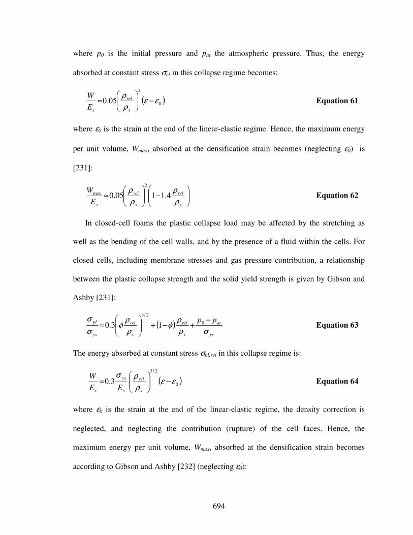
694
where p0 is the initial pressure and pat the atmospheric pressure. Thus, the energy
absorbed at constant stress σel in this collapse regime becomes:
( )0
2
05.0 εερ
ρ−
≈
s
rel
sE
W Equation 61
where ε0 is the strain at the end of the linear-elastic regime. Hence, the maximum energy
per unit volume, Wmax, absorbed at the densification strain becomes (neglecting ε0) is
[231]:
−
≈
s
rel
s
rel
sE
W
ρ
ρ
ρ
ρ4.1105.0
2
max Equation 62
In closed-cell foams the plastic collapse load may be affected by the stretching as
well as the bending of the cell walls, and by the presence of a fluid within the cells. For
closed cells, including membrane stresses and gas pressure contribution, a relationship
between the plastic collapse strength and the solid yield strength is given by Gibson and
Ashby [231]:
( )ys
at
s
rel
s
rel
ys
pl pp
σρ
ρφ
ρ
ρφ
σ
σ −+−+
≈ 0
2/3
13.0 Equation 63
The energy absorbed at constant stress σpl,rel in this collapse regime is:
( )0
2/3
3.0 εερ
ρσ−
≈
s
rel
s
ys
s EE
W Equation 64
where ε0 is the strain at the end of the linear-elastic regime, the density correction is
neglected, and neglecting the contribution (rupture) of the cell faces. Hence, the
maximum energy per unit volume, Wmax, absorbed at the densification strain becomes
according to Gibson and Ashby [232] (neglecting ε0):
695
−
≈
s
rel
s
rel
s
ys
s EE
W
ρ
ρ
ρ
ρσ4.113.0
2/3
max Equation 65
Since the contribution (rupture) of the cell faces is neglected, this result for closed cells
equals the result for open cells.
According to Gibson and Ashby [231], the following relationship holds for closed
cells of brittle materials including membrane stresses:
( )s
rel
s
rel
fs
cr
ρ
ρφ
ρ
ρφ
σ
σ−+
≈ 165.0
2/3
Equation 66
Due to their brittle nature, the energy dissipation for brittle foams is not considered.
For plastic foams, which are much stiffer and stronger than elastomeric foams, the
fluid within the cells plays a less important role concerning energy absorption and is
hence usually neglected.
The plateau stress and hence energy absorbed per unit volume depend on the strain-
rate and temperature through the intrinsic strain-rate and temperature dependence of the
cell wall material. The temperature and strain-rate dependence of foams are inherent
properties of the material of which they are made and of the fluid behavior contained in
the cells of the foam. The moduli and strength of rigid foams (metals and ceramics well
below their melting points as well as polymers well below their glass temperatures)
decrease linearly as the temperature rises [231]. Increasing the strain-rate does not affect
their moduli but increases their strength. For semi-rigid foams (polymer foams used at a
temperature close to the glass temperature Tg of the base polymer) both the moduli and
strength increase with strain-rate, sometimes dramatically. Also, the modulus depends
strongly on temperature. For elastomeric foams, their moduli increase slightly with
increasing temperature, but they are almost independent of strain-rate. Also, the plastic
696
collapse strength of a foam is directly proportional to the yield strength of the solid of
which it is made. As the foam is heated, the yield strength falls; increasing strain-rate on
the other hand causes a slight increase in yield strength.
IX b) Honeycomb Cores
In the general, a cellular material in which a two-dimensional array of polygons is
packed to fill a plane area is referred to as a honeycomb [231], also featuring “optimal”
energy dissipation, i.e., plateau stress-strain curve, characteristics. Studies on
honeycombs [190] have shown that the in-plane relative stiffness E/Es scales as 1*ρrel3.
According to Sypeck and Wadley [648], in-plane compressive relative strength σ/σys
(exemplified for a single- or multi-layer diamond-celled lattice core with a typical semi-
angle of ω = 45o) scales with 0.5*ρrel (neglecting elastic buckling). For out-of-plane
honeycombs the relative stiffness scales with 1*ρrel [190]. Exemplified for hexagonal-
and square-honeycomb cores, the out-of-plane relative strength (neglecting elastic
buckling) scales as 4.85*ρrel5/3
(according to Ashby and coauthors [29]) and 1*ρrel
(according to Xue and Hutchinson [751]) respectively. In general, the densification strain
can then be approximated by εD = 0.8 – 1.75ρrel. Even though honeycombs outperform
foams on a performance basis, honeycombs are generally more expensive and less
durable. Honeycombs are highly anisotropic and especially costly to configure as cores
for curved structures. Hence, foams may become competitive on a
performance/durability/affordability basis particularly for shell structures and curved
panels.
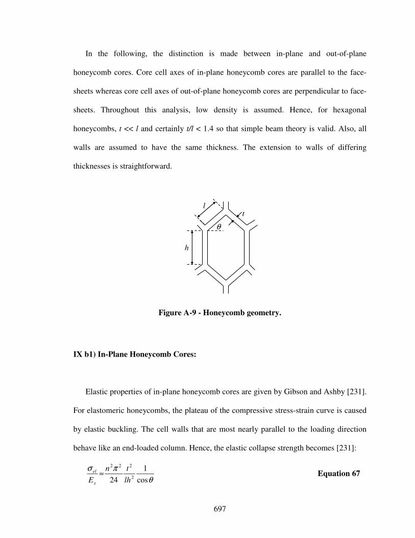
697
In the following, the distinction is made between in-plane and out-of-plane
honeycomb cores. Core cell axes of in-plane honeycomb cores are parallel to the face-
sheets whereas core cell axes of out-of-plane honeycomb cores are perpendicular to face-
sheets. Throughout this analysis, low density is assumed. Hence, for hexagonal
honeycombs, t << l and certainly t/l < 1.4 so that simple beam theory is valid. Also, all
walls are assumed to have the same thickness. The extension to walls of differing
thicknesses is straightforward.
l
h
θ
t
Figure A-9 - Honeycomb geometry.
IX b1) In-Plane Honeycomb Cores:
Elastic properties of in-plane honeycomb cores are given by Gibson and Ashby [231].
For elastomeric honeycombs, the plateau of the compressive stress-strain curve is caused
by elastic buckling. The cell walls that are most nearly parallel to the loading direction
behave like an end-loaded column. Hence, the elastic collapse strength becomes [231]:
θ
πσ
cos
1
24 2
222
lh
tn
Es
el ≈ Equation 67
698
where n is an end constraint factor which equals 0.69 for regular hexagons.
Honeycombs made of elastic-plastic solids collapse plastically when the bending
moment in the cell walls reaches the fully plastic moment, yielding a plateau both in
compression and in tension at the plastic collapse stress σpl given by Gibson and Ashby
[231]:
θθσ
σ
sinsin2
12
+
≈
l
hl
t
ys
pl Equation 68
For brittle material, not considering the effect of defects, the critical stress becomes
[231]:
2
sinsin3
1
+
≈l
t
l
hys
cr
θθσ
σ Equation 69
More refined analyses, considering the effect of defects, can be found in the literature
[231]. Here, creep and viscoelastic deformation is also neglected. However, the relative
density for hexagonal honeycombs can be calculated as [231]:
θθρ
ρ
cossin2
2
+
+
=
l
h
l
h
l
t
s
Equation 70
Moreover, the densification strain is obtained from [231]:
θθ
ε
cossin2
2
4.11
+
+
−=
l
h
l
h
l
t
D Equation 71
699
IX b2) Out-Of-Plane Honeycomb Cores:
If a honeycomb is compressed along the cell axis, the initial linear-elastic
deformation involves significant axial or shear deformations of the cell walls themselves.
Beyond a critical strain, the linear elastic regime is truncated by buckling (elastic for an
elastomer, plastic for a metal or rigid polymer), followed by structural collapse at an
approximately constant plateau stress. Final failure is by tearing or crushing, when the
structure densifies and its stiffness increases rapidly, giving a final, steeply rising portion
of the stress-strain curve. An increase in the relative density of a honeycomb increases
the relative thickness of the cell walls. Then the resistance to cell collapse goes up, giving
a higher modulus and plateau stress; and the cells collapse sooner, reducing the strain at
which densification begins.
For clamped sandwich plates subject to transverse loads, the important basic stressing
histories of the core are: (1) crushing normal to the sandwich faces, (2) out-of-plane
shear, and (3) in-plane stretching. Out-of-plane honeycombs give high energy absorption
by the formation of a succession of folds of each cell, with hoop stretching of the cell
wall between each fold. However, the formation of each successive fold leads to
oscillations in the collapse stress. The models presented below are premised on the
assumption that plastic yielding occurs prior to elastic buckling in the core. Were that not
the case, the core would be underestimated because cores that buckle elastically are not
nearly as effective in absorbing energy as those that yield plastically before buckling
[752].
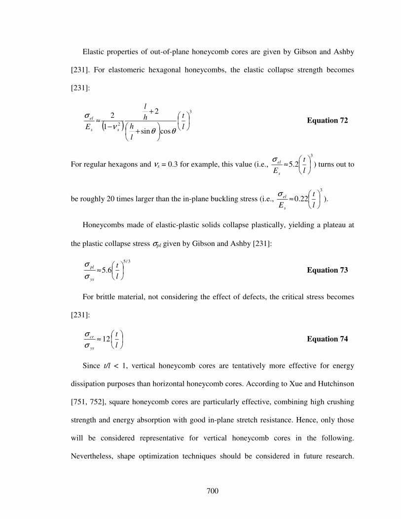
700
Elastic properties of out-of-plane honeycomb cores are given by Gibson and Ashby
[231]. For elastomeric hexagonal honeycombs, the elastic collapse strength becomes
[231]:
( )
3
2
cossin
2
1
2
+
+
−≈
l
t
l
h
h
l
E ss
el
θθν
σ Equation 72
For regular hexagons and νs = 0.3 for example, this value (i.e.,
3
2.5
≈
l
t
Es
elσ) turns out to
be roughly 20 times larger than the in-plane buckling stress (i.e.,
3
22.0
≈
l
t
Es
elσ).
Honeycombs made of elastic-plastic solids collapse plastically, yielding a plateau at
the plastic collapse stress σpl given by Gibson and Ashby [231]:
3/5
6.5
≈
l
t
ys
pl
σ
σ Equation 73
For brittle material, not considering the effect of defects, the critical stress becomes
[231]:
≈
l
t
ys
cr 12σ
σ Equation 74
Since t/l < 1, vertical honeycomb cores are tentatively more effective for energy
dissipation purposes than horizontal honeycomb cores. According to Xue and Hutchinson
[751, 752], square honeycomb cores are particularly effective, combining high crushing
strength and energy absorption with good in-plane stretch resistance. Hence, only those
will be considered representative for vertical honeycomb cores in the following.
Nevertheless, shape optimization techniques should be considered in future research.
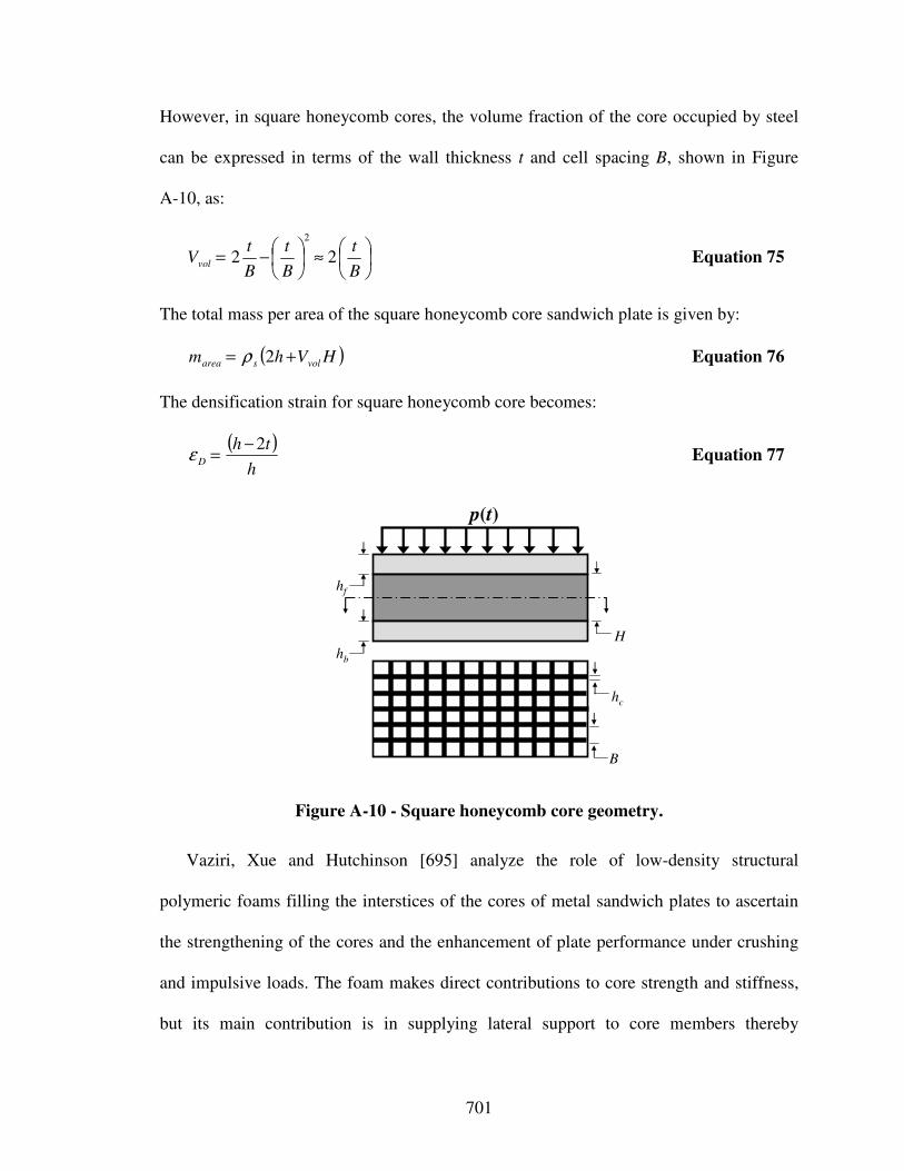
701
However, in square honeycomb cores, the volume fraction of the core occupied by steel
can be expressed in terms of the wall thickness t and cell spacing B, shown in Figure
A-10, as:
≈
−=
B
t
B
t
B
tVvol 22
2
Equation 75
The total mass per area of the square honeycomb core sandwich plate is given by:
( )HVhm volsarea += 2ρ Equation 76
The densification strain for square honeycomb core becomes:
( )
h
thD
2−=ε Equation 77
hf
hb
hc
B
H
p(t)
Figure A-10 - Square honeycomb core geometry.
Vaziri, Xue and Hutchinson [695] analyze the role of low-density structural
polymeric foams filling the interstices of the cores of metal sandwich plates to ascertain
the strengthening of the cores and the enhancement of plate performance under crushing
and impulsive loads. The foam makes direct contributions to core strength and stiffness,
but its main contribution is in supplying lateral support to core members thereby
702
enhancing the buckling strength of these members. However, Vaziri, Xue and Hutchinson
assess performance at fixed total weight of the sandwich plate such that the weight of the
foam is traded against that of the metal. The tradeoff against enhancement of the buckling
resistance of the core webs due to lateral support of the foam is the inevitable loss in
bending and/or stretching strength accompanying the reduction in metal required to pay
for the weight of the foam. Thus, the outcome of the comparative study suggests that
plates with foam-filled cores can perform as well, or nearly as well, as plates of the same
weight with unfilled cores. They conclude that the decision on use of foams in the cores
is therefore likely to rest on multifunctional advantages such as acoustic and thermal
insulation or environmental isolation of core interstices.
Since dynamic effects play a significant role in the behavior of the core of square
honeycombs in applications where sandwich plates must absorb significant energy in
crushing under intense impulsive loads, three distinct dynamic effects were further
analyzed by Xue and Hutchinson [754], namely: (i) inertial resistance, (ii) inertial
stabilization of webs against buckling, and (iii) material strain-rate dependence.
Moreover, sandwich panels with honeycomb cores compressed along the cell axis have
further been analyzed in the literature [232, 527, 750-754].
703
X) Crushing of Microtruss Structures
Cellular solids can deform by either the bending or stretching of the cell walls. While
most cellular solids are bending-dominated, those that are stretching-dominated are much
more weight-efficient for structural applications. Deshpande, Ashby and Fleck [161]
investigated the topological criteria that dictate the deformation mechanism of a cellular
solid by analyzing the rigidity of pin-jointed frameworks comprising inextensional struts.
They show that stretching dominated structures (where struts support axial loads, tensile
in some, compressive in others when loaded) offer greater stiffness and strength per unit
weight than those in which the dominant mode of deformation is by bending. For
example, a stretching-dominated structure is expected to be about then times as stiff and
about three times as strong as a bending-dominated foam for a relative density ρrel = 0.1;
and these ratios increase with diminishing ρrel.
Topological criteria that dictate whether a cellular material will be bending or
stretching dominated with the overall aim of developing an understanding of the
microstructure that maximizes the strength (or stiffness) to weight ratio are discussed by
Deshpande, Ashby and Fleck [161]. Hence, periodic truss structures with a sufficiently
large connectivity at each node to provide for structural rigidity that fulfill these
topological criteria at microscales are referred to as microtruss structures. Under all
applied macroscopic stress states the individual struts deform by local stretching rather
than by bending. Consequently, the stiffness and strength of lattice materials scale
linearly with their relative density ρrel. For relative densities higher than 0.2, the struts are
stocky and collapse at an almost constant load, making for high energy absorption [164].
704
However, the choice of topology is crucial: it must be designed such that when sheared,
the trusses are in either tension or compression with no bending [191]. Among all
possible truss topologies, only a small subset has the characteristic that the trusses stretch
and compress without bending. Most prominent are tetragonal [124, 650] and pyramidal
trusses [772]. Others exist, such as Kagome truss structures (i.e., truss structures
exhibiting a mix of hexagonal and triangular struts), but they have yet to be fully
characterized [191]. Nevertheless, Kagome structure are very promising, since they
exhibit the same toological properties as the natural random cellular structures of an
armadillo shell structure and young soap froth structure, as investigated by Parfait-Pignol
and coauthors [486]. However, the following results are presented for situations wherein
the trusses fail by yielding/plastic buckling – the common failure modes for optimized
panels.
For example, Zok and coauthors [772] find the following out-of-plane relationships of
the relative stiffness and strength for pyramidal truss cores with an angle of 45o between
the core members and the face sheet:
s
sE
Eρ25.0≈ Equation 78
s
ys
ρσ
σ5.0≈ Equation 79
The relative density of pyramidal truss cores is
2
22
=
c
crel
H
tρ where tc is the truss
core member thickness and Hc is the core height. For ρrel between 2 and 12 %, the
densification strain usually is 0.6.
705
For tetrahedral truss cores on the other hand, Sypeck and Wadley [650] find the
following out-of-plane relationships of the relative stiffness and strength:
s
sE
Eρ44.0≈ Equation 80
s
ys
ρσ
σ66.0≈ Equation 81
for a relative density of 2
23
L
whrel =ρ where h is the truss core member thickness, w is
the truss core member width and L is the truss core member length. In this case, the angle
each member makes with a line extending from the center of the triad base to its peak is
30 degrees, according to Sypeck and Wadley [650] the angle for maximum shear
strength.
New efficient casting-based procedures have been devised which permit entire truss
structure components to be produced at scales ranging from millimeters to tens of
centimeters. Also, electro-deposition has been used to form truss structure at even smaller
scales with elements whose diameters can be as small as fifty microns. Motivated by
these recent advances in manufacturing technology, attention has been focused on
minimum weight sandwich plates comprised of truss cores faced with planar frameworks.
For example, Wallach and Gibson [700] have reported a combined experimental and
finite element investigation of the strength and stiffness of a truss plate made of a
structure that has a periodic unit cell with fully triangulated members, i.e., triangulated
faces and a pyramidal truss core. Tetrahedral truss cores faced with fully triangulated
planar trusses or solid sheet faces have been analyzed by Wicks and Hutchinson [724]
and Deshpande and Fleck [162]. They show that optimized truss panels are exceptionally
706
weight-efficient for carrying bending and compression loads and comparable to the
alternatives of honeycomb core sandwich panels or stringer stiffened plates. Analytical
expressions for the stiffness and strength of a broad class of pyramidal and tetrahedral
truss cores are derived by Deshpande and Fleck [162]. A striking result is that the normal
stiffness, normal strength and transverse shear stiffness are the same for both core
geometries at a given relative density ρrel and strut inclination angle ω, where the normal
stiffness and strength at fixed ρrel are maximized by selecting ω as close to π/2 as
possible. Deshpande, Fleck and Ashby [163] investigate effective mechanical properties
of the octet-truss lattice structured material, both experimentally and theoretically. The
nodes of the octet-truss are configured as a 3 dimensional face-centered cubic lattice
structure with each strut of an octahedral cell shared between two neighboring cells.
As described above, the modulus and initial yield strength of a stretching-dominated
cellular solid are much greater than those of a bending dominated cellular material of the
same relative density. This makes stretching-dominated cellular solids attractive
alternatives to bending-dominated foamed materials for lightweight structural
applications. Also, lattice materials have additional potential by virtue of their open
structure of multi-functional applications and are relatively cheap. However, unlike
bending dominated foams, in compression the stretching-dominated materials have a
softening post-yield response due to the buckling of the struts. Thus, these materials may
be less attractive as energy-absorbers since this application requires a stress-strain
response with a long, flat plateau [161].
However, lattice materials are designed to maximize the strength (or stiffness) to
weight ratio of nearly isotropic cellular materials. There exist a variety of multi-length-
707
scale cellular microstructures that attain both the bulk and shear Hashin-Shtrikman
bounds [251]. Deshpande, Fleck and Ashby [163] conjecture that lattice materials with
face-centered cubic microstructures are close to attaining the Hashin-Shtrikman bounds
and hence close to the optimal single length-scale cellular microstructure. The stiffness
and strength of the octet-truss lattice material for example are seen to be about half the
theoretical upper bound for relative density values between 0.01 and 0.1 [163].
Lattice materials are promising material systems and thus focus of many current
research efforts. For example, coupled plastic wave propagation and column buckling in
the context of lattice materials is analyzed by Vaughn, Canning and Hutchinson [693].
Lee and coauthors [363] also further investigate the quasi-static and dynamic
compressive behavior of pyramidal truss cores using a combination of experimental
techniques. Also, microstruss structures of smart materials with full structural capabilities
are currently investigated. For example, Holnicki-Szulc and coauthors [272] theoretically
analyze the concept of high-performance impact structures based on shape-memory-alloy
microstruss structures, more specifically an adaptive micro-structure called the adaptive
multifolding microstructure. The adaptive multifolding microstructure consists of micro-
fuses each of which is designed as a stack of thin washers made of shape-memory-alloy
or piezo-electric (controllable) devices. To achieve an additional value of energy
dissipation (due to synergy of repetitive use of dissipaters), a pre-designed optimal
distribution of yield stress levels in all fuses is designed, triggering a desired sequence of
load collapses.
708
XI) Textile-Based Weaves
As summarized by Spyeck and Wadley [649], open cell periodic metal truss
structures can exhibit significantly higher stiffness and strength than stochastic cellular
metal structures of the same relative density while still providing high mechanical energy
absorption (comparable to axially crushed thin-walled cylinders). Relative mechanical
properties are higher in the load support direction because of the reduced bending
inherent in truss designs, becoming more pronounced as the relative density decreases. In
truss materials, individual cells can be small (a few millimeters). However, low-density
textile-based weaves have the compliance and necessary open space for cell collapse
thereby absorbing large amounts of energy when compressed. Properties can be
manipulated by modifying the truss architectures and material [649].
Textile-based weaves have been analyzed by various researchers [191, 649, 771].
Sypeck and Wadley [649] for example propose a proven textile-based approach to the
synthesis of periodic metal microtruss laminates consisting of (i) selecting a wire weave,
(ii) laying up the mesh, and (iii) joining using a transient liquid phase. In their studies,
nichrome (Ni-24Fe-16Cr) wire cloth exhibits a linear dependence of stiffness (0.5ρrel)
and strength (0.5ρrel) upon relative density, if buckling does not occur. Also, it has about
three-fourths of the energy absorptive capacity of an axially crushed thin-walled tube of
the same material and relative density. However, Spyeck and Wadley note that if
delaminations near the edges of their sample had occurred early on and these laminae
were not plastically deformed (worked) to their full potential by test end, the possibility
for additional energy absorption exists. However, Evans [191] states that the exceptional
709
performance of this plain-weave core in the diamond configuration is particularly
encouraging.
XII) Crushing of Fibrous Composite Structures
Fibrous core sandwich panels are thin, lightweight structures with face-sheets
separated by an irregular arrangement of independent fibers; the fibers have a random
angle of fiber inclination to the faceplates and a range of initial curvatures [769]. These
core configurations provide high bending stiffness and light weight, together with good
formability and vibration damping. The total thickness of the panel is small (1-1.5 mm)
so that the material can be formed similar to a conventional monolithic metallic sheet.
Also, the core arrangement is irregular, i.e., there is no periodic unit for the core
geometry. Zhou and Stronge [769] analyze the effects of core morphology (initial
curvature, angle of inclination of core fibers, volume fraction and material properties) on
the through-thickness elastic moduli, compressive strength and the through-thickness
shear strength of the fibrous core.
Zhou and Stronge find that improvement in stiffness and strength can be obtained by
means of either large diameter fibers of circular cross-section or by tubular fibers. Also,
they state that if solid fibers are replaced with thin wall tubes of the same diameter while
area density of the panel remains constant, the stiffness and strength can be improved to
double that of core with solid fibers. The model developed by Zhou and Stronge however
does not capture the plateau phase of the experimental stress-strain curve. Moreover,
710
these panels have small thickness so that they may be pressed into 3D curvature in a
forming operation. Hence, fibrous cores are promising candidates for future research, but
are not considered in this work.
XIII) Crushing of (Optimal) Multi-Length-Scale Composites
Isotropic cellular materials that attain theoretical upper bounds for the bulk and shear
moduli of a voided solid maximize the stiffness to weight ratio [163]. Since the elastic
properties of an isotropic composite material can be described by its effective bulk and
shear modulus, theoretical bounds for these properties have been investigated by many
researchers, as reviewed by Sigmund [593]. However, the Hashin-Shtrikman bounds
[251] are widely accepted. A number of classes of two phase composites attain these
bounds. In this work, these composites are referred to as (optimal) multi-length scale
composites. So far, four optimal multi-length scale composites are known: coated sphere
assemblage, rank-3-laminate, Vigdergauz microstructure, and Sigmund microstructure.
For example, Norris [455] employs a coated sphere architecture to propose
differential schemes for constructing composite structures with the extremal Hashin-
Shtrikman bulk and shear moduli. Milton [428] on the other hand uses a laminate
microstructure to propose differential schemes for constructing composite structures with
the extremal Hashin-Shtrikman bulk and shear moduli. Also, Vigdergauz [696] presents
isotropic two-dimensional square symmetric composites with optimal shape of single
inclusions.
711
Francfort and Murat [215] suggest rank laminates which attain both the bulk and
shear H-S bounds with a finite number of layering directions. Rank laminates are
obtained by a sequential process where at each stage the previous laminate is laminated
again with a single phase (always the same) in a new direction. Thus, a rank-n laminate is
produced by n such successive laminations. While in the 2D case isotropic rank-3
lamiantes have the extremal bulk and shear moduli, in the 3D case rank-6 laminates are
the optimal microstructures.
Sigmund [593] proposes a statistically isotropic (or at least square symmetric) two-
phase microstructure, consisting of disconnected convect polygonal regions with pure
phase 1 or 2 material connected by laminated regions of the phases in equal proportions,
for which exact solutions for the hydrostatic loading case exist. This composite has bulk
modulus equal to either the upper or the lower Hashin-Shtrikman bound if the lamination
direction is perpendicular to the stiffer or lower phase respectively. According to
Sigmund [593], an isotropic honeycomb-like hexagonal microstructure belonging to this
class of composite has maximum bulk modulus and lower shear modulus than any
previously known composite.
Knowledge of the multiphase composite structures that achieve the optimal Hashin-
Shtrikman bounds [251] for effective elastic moduli and conductivity is of fundamental
and practical value. However, with the only except of the single-length-scale structures
that achieve the bulk-modulus and conductivity bound for volume fractions found by
Vigdergauz, all of the known optimal structures are multiscale structures and therefore
not manufacturable [288]. Hence, they are not further considered in this work.
712
XIV) Crushing of Auxetic Material Structures
As described above, cellular structures are used to design structural components with
mechanical properties and low weight characteristics superior to those of solid
components [624]. Chiral geometries in particular, originally proposed by Prall and
Lakes [355, 512], offer exceptional possibilities for the design of truss-core sandwich
panels for passive sound absorption [366, 625] and dynamic response [626], airfoils with
passive and active shape control capabilities [67], and honeycomb panels with increased
elastic buckling strength [623]. Also, auxetic (or negative Poisson’s ratio material) have
found potential applications in damage tolerant laminates [17], microwave absorbers
[611] and medical prosthesis [406].
The allowable range of Poisson’s ratio in three-dimensional isotropic solids is from -1
to ½ [225]. Most common materials have a Poisson’s ratio close to 1/3, however, rubbery
materials have values approaching ½; they readily undergo shear deformations, governed
by the shear modulus G, but resist volumetric (bulk) deformation governed by the bulk
modulus K, so G << K. A solid with a Poisson’s ration close to -1 would be the opposite
of rubber: difficult to shear but easy to deform volumetrically: G >> K.
Material structures having auxetic characteristics, i.e., featuring a negative Poisson’s
ratio behavior, include a special subset of foams [133, 220, 353], long fiber composites,
[16], microporous polymers [354], aggregates of crystals of α-cristobalite [13], hinged
frameworks [19], linked structures [192, 358], as well as honeycombs [230, 232, 354,
566, 712]. Honeycombs are so far preferred, since the negative Poisson’s ratio behavior
713
implies a stiffening geometric effect, which leads to increase in-plane indentation
resistance, shear modulus an compressive strength [263, 566]. The auxetic behavior also
leads so a synclastic curvature feature which is extremely useful in manufacturing curved
sandwich shells [623]. However, only recently, improved manufacturing processes have
made unique composite materials with auxetic characteristics more affordable [513].
A hexagonal chiral geometry is composed of circular elements (nodes) of equal radii
joined by straight ligaments (ribs), which are tangent to the nodes. This configuration
provides the cellular assembly with distinctive mechanical properties, such as high shear
rigidity, isotropic negative Poisson’s ratio behavior (achieved by an unrolling action
where cells wind in upon themselves during compression), and a deformation
mechanism, driven by bending of the ligaments into a sigmoid shape and equal rotation
of the nodes, allowing high strains in the elastic range of the constitutive material [623].
For hexagonal chiral cells, the in-plane Poisson’s ratio of -1 remains substantially
constant up to 25 percent of applied strain in one principal direction, while the
honeycomb structure recovers almost entirely its original dimensions [67].
Spadoni and coauthors [623] analyze the out-of-plane buckling behavior of a chiral
assembly for its application as an alternative honeycomb design and to assess its strength
under flat-wise compression through analytical formulas and a linear buckling analysis
carried out using the Finite Element method. Increased compressive strength of auxetic
honeycombs compared to traditional honeycombs are documented in [767]. Spadoni and
coauthors [623] find that both global and local buckling are high per unit weight than the
global critical load of auxetic and hexagonal configurations. They note that the chiral
configuration produces strong changes in the normalized critical stress whereas

714
hexagonal honeycombs on the contrary feature strength characteristics which only
depend on the relative density of the assembly. Spadoni and coauthors [568, 623] derive
expressions for the relative density, Young’s modulus and critical elastic buckling
strength.
These expressions however refer to elastic buckling only, are essentially derived from
the compressive strength of cylinders, are valid for short cylinders only and hence limited
in their application. Moreover, analyses and experimental results so far do not show the
plateau at a sufficiently high stress level required for enhanced energy dissipation.
However, results obtained so far are promising and motivate current and future research
in smart materials and structures. For example, Scarpa, Hassan, and Ruzzene [567]
combine a chiral honeycomb topology and the use of shape memory alloys as core
material to explore shape restoring capabilities for use in deployable space antenna
reflectors and structure energy absorption applications.
XV) Compression of Microtruss Mechanisms
Machine augmented composite materials first introduced by Hawkins [252], in this
work referred to as micrtotruss mechanisms, are composite formed by embedding simple
microscale machines, with or instead of fiber or particulate reinforcements, in a matrix
material to obtain a multifunctional material with new properties. The machines may take
on many different forms and serve to modify power, force, or motion in different ways,
hence creating as many different mechanical properties as there are possibilities for the
715
cross-sectional shapes of machines. Machine-augmented composites consist of simple,
small machines that are for example hollow fibers formed by extrusion whose cross
sections resemble slanted box girders.
So far, one unique property of a machine augmented composites is its ability to
convert a compressive force into a shear force, and vice versa, simply by the geometry of
its angled sidewalls [253]. For example, a four-bar linkage with slanted walls is a simple
stress-conversion machine that converts shear forces into tensile/compressive forces and
vice versa. If shear forces are applied to the machine, the slanted walls change their
angle, forcing the top and bottom plates to move apart. This movement causes
compressive forces on any adjacent contacting material. Conversely, if compressive
forces are applied to the top and the bottom faces, the machine imposes shear forces on
any adjacent abutting material. In a four-bar linkage, an angle of 45 degrees yields a 1:1
conversion of compression displacement to shear displacement, and this ratio goes to
zero as the angel increases to 90 degrees. Applications for this concept include structures
in which easy assembly but subsequent firm grip are desired. Another interesting
application is sonic damping, wherein an array of specially shaped machines serves to
transform in incident (planar) sound wave into two out-of-phase waves that cancel each
other.
Other conceptual designs of machines that when embedded in a material exhibit
different mechanical properties, such as a nonlinear modulus, negative Poisson’s ratio or
extended strain to failure are proposed in the literature [323]. McCutcheon [412] for
example analyzes machine augmented composites in the form of fluid filled tubes, where
the tube cross-sectional geometry induces fluid flow when it is deformed in its plane.
716
This flow dissipates mechanical energy and thus provide the composite material with
attractive damping properties. Also, Kim [323] studies machine augmented composites
for stiffened structures that maintain inherent damping. It is noted, that the use of
machine augmented composites may be beneficial in providing new methods for energy
control through their capability of influencing forces during impacts [661]. Results
however are still focus of current research.
Theoretically, machine-augmented composites might be formed by embedding any
sort of mechanisms in a matrix material. These mechanisms may include:
• Wheel-gears (friction-/form-locking)
• Cam-mechansisms, worm/helical gears, gate geards
• Belt-/chain-drives (friction-/form-locking)
• 4-bar-turning/sliding-pair linkages, multilink mechanisms
Potentially, machine-augmented composites might also be formed by embedding micro-
electro-mechanical systems (MEMS). MEMS are micro-machines that have simultaneous
electrical and mechanical function. However, a more precise definition is that a MEMS is
a device that combines sensing, actuating and computing. Hence, they usually consist out
of silicon, which is three times stronger than steel, but with a density lighter than that of
aluminum. Silicon also has the near ideal combination of high thermal conductivity with
low thermal expansion. On a dimensionless performance level, silicon outperforms all
other traditional mechanical materials. Also, an entire fabrication industry is already
tooled for the manufacturing and machining of silicon components at the micro-scale.
However, currently one of the most interesting direction is the development of micro
energy systems.
717
XVI) Martensitic Transformations
Two unique properties are made possible through a solid state phase change, that is a
molecular rearrangement, which occurs in shape memory alloys or polymers: pseudo-
elasticity and shape memory effect, more specifically stress and heat induced martensitic
transformations respectively. James and Hane [301], review theoretical research on
martensitic phase transformations. Otsuka and Ren [465] focus on important
developments on martensitic transformations in non-ferrous shape memory alloys.
Martensitic transformations involve a solid state phase change. During a solid state
phase change molecular rearrangement is occurring, but the molecules remain closely
packed so that the substance remains a solid. In most shape memory alloys, a temperature
change of only about 10°C is necessary to initiate this phase change. The two phases,
which occur are Martensite and Austenite. Martensite is the relatively soft and easily
deformed phase of shape memory alloys which exists at lower temperatures. The
molecular structure in this phase is twinned. Austenite, the stronger phase of shape
memory alloys, occurs at higher temperatures. The shape of the Austenite structure is
cubic. The un-deformed Martensite phase is the same size and shape as the cubic
Austenite phase on a macroscopic scale, so that no change in size or shape is visible in
shape memory alloys until the Martensite is deformed.
Whereas the heat induced martensitic transformations refer to the temperature-
dependent ability of a particular kind of alloy or polymer to a previously memorized or
preset shape (shape memory effect), stress induced martensitic transformations refer to
the ability of a material to undergo enormous elastic or reversible deformation (pseudo-

718
elasticity). This pseudo-elasticity features the plateau stress-deformation characteristic
crucial for enhanced energy dissipation. Pseudo-elasticity occurs in shape memory alloys
when the alloy is completely composed of Austenite. Unlike the shape memory effect,
pseudo-elasticity occurs without a change in temperature. The load on the shape memory
alloy is increased until the Austenite becomes transformed into Martensite simply due to
the loading. The loading is absorbed by the softer Martensite, but as soon as the loading
is decreased the Martensite begins to transform back to Austenite, and the material
springs back to its original shape.
The concept of high-performance impact structures based on stress-induced
martensitic transformations has been formulated theoretically [271]. However, so far
pseudo-elasticity involves plateau stress-deformation characteristics only at low stress
levels. Also, alloys featuring stress-induced martensitic transformations are still relatively
expensive to manufacture and machine compared to other materials such as steel and
aluminum. Also, most SMA's have poor fatigue properties.

719
APPENDIX B: REALIZABILITY AND FUNCTIONALITY
ATTRIBUTE RATINGS FOR SELECTION DSPS
In the implementation of selection DSPs throughout this work, the realizability
indicator is used for qualitative information on an interval scale representing normalized
manufacturing complexity and flexibility, as well as resistance against environmental
effects. The viewpoint is presented in Table 7-8. Bounds range from 0 to 1. Similarly, a
functionality indicator is used for qualitative information on an interval scale representing
normalized functionality and potential for multifunctional enhancement. The viewpoint is
presented in Table 7-9. Bounds range from 0 to 1. As described in Section 7.3.6, the
realizability and functionality indicators are based on qualitative information only.
However, in the early stages of design such indicators are required to account for
simplifying assumptions, such as neglecting the effect high temperatures during the event
of collisions and explosions.
However, attributes can not be rated accurately for these qualitative indicators. Hence,
results are to be critically evaluated. Since relative importance and ratings are not know
very accurately, a post-solution sensitivity analysis is performed using exact interval
arithmetic using DSIDES. As a result of this analysis, the best possible and worst
possible rank for an alternative (taking the uncertainty into consideration) is obtained.
Nevertheless, the attribute ratings used for selection in sDSPs are subjective, similar to
the utility functions used in cDSPs. But, attribute ratings are not arbitrary and therefore,
are described in greater in the following. Depending on how important an alternative’s
characteristics with respect to their specific function are, attribute ratings might vary.
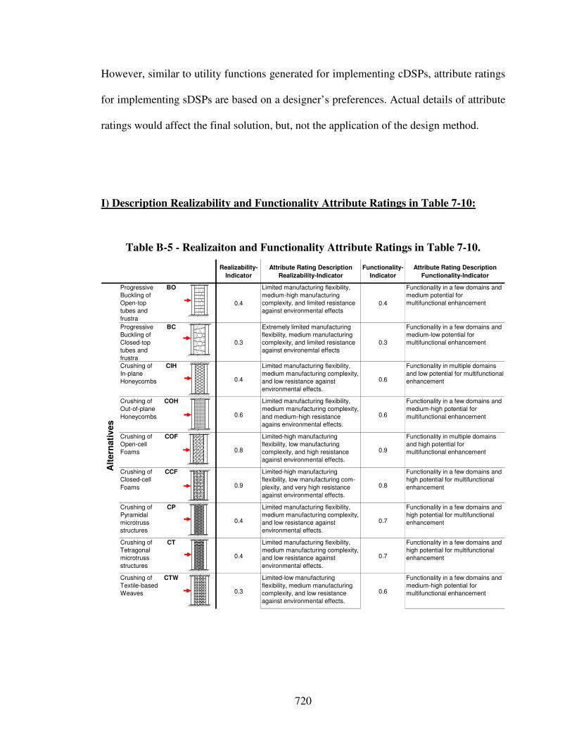
720
However, similar to utility functions generated for implementing cDSPs, attribute ratings
for implementing sDSPs are based on a designer’s preferences. Actual details of attribute
ratings would affect the final solution, but, not the application of the design method.
I) Description Realizability and Functionality Attribute Ratings in Table 7-10:
Table B-5 - Realizaiton and Functionality Attribute Ratings in Table 7-10.
Realizability-
Indicator
Attribute Rating Description
Realizability-Indicator
Functionality-
Indicator
Attribute Rating Description
Functionality-Indicator
Progressive
Buckling of
Open-top
tubes and
frustra
BO
0.4
Limited manufacturing flexibility,
medium-high manufacturing
complexity, and limited resistance
against environmental effects0.4
Functionality in a few domains and
medium potential for
multifunctional enhancement
Progressive
Buckling of
Closed-top
tubes and
frustra
BC
0.3
Extremely limited manufacturing
flexibility, medium manufacturing
complexity, and limited resistance
against environemtal effects
0.3
Functionality in a few domains and
medium-low potential for
multifunctional enhancement
Crushing of
In-plane
Honeycombs
CIH
0.4
Limited manufacturing flexibility,
medium manufacturing complexity,
and low resistance against
environmental effects.
0.6
Functionality in multiple domains
and low potential for multifunctional
enhancement
Crushing of
Out-of-plane
Honeycombs
COH
0.6
Limited manufacturing flexibility,
medium manufacturing complexity,
and medium-high resistance
agains environmental effects.
0.6
Functionality in a few domains and
medium-high potential for
multifunctional enhancement
Crushing of
Open-cell
Foams
COF
0.8
Limited-high manufacturing
flexibility, low manufacturing
complexity, and high resistance
against environmental effects.
0.9
Functionality in multiple domains
and high potential for
multifunctional enhancement
Crushing of
Closed-cell
Foams
CCF
0.9
Limited-high manufacturing
flexibility, low manufacturing com-
plexity, and very high resistance
against environmental effects.
0.8
Functionality in a few domains and
high potential for multifunctional
enhancement
Crushing of
Pyramidal
microtruss
structures
CP
0.4
Limited manufacturing flexibility,
medium manufacturing complexity,
and low resistance against
environmental effects.
0.7
Functionality in a few domains and
high potential for multifunctional
enhancement
Crushing of
Tetragonal
microtruss
structures
CT
0.4
Limited manufacturing flexibility,
medium manufacturing complexity,
and low resistance against
environmental effects.
0.7
Functionality in a few domains and
high potential for multifunctional
enhancement
Crushing of
Textile-based
Weaves
CTW
0.3
Limited-low manufacturing
flexibility, medium manufacturing
complexity, and low resistance
against environmental effects.
0.6
Functionality in a few domains and
medium-high potential for
multifunctional enhancement
Alt
ern
ati
ve
s
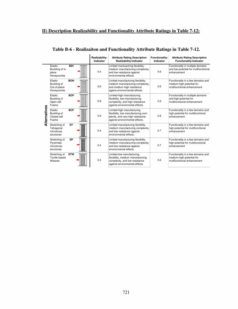
721
II) Description Realizability and Functionality Attribute Ratings in Table 7-12:
Table B-6 - Realizaiton and Functionality Attribute Ratings in Table 7-12.
Realizability-
Indicator
Attribute Rating Description
Realizability-Indicator
Functionality-
Indicator
Attribute Rating Description
Functionality-Indicator
Elastic
Buckling of In-
plane
Honeycombs
BIH
0.4
Limited manfuactring flexibility,
medium manufacturing complexity,
and low resistance against
environmental effects.
0.6
Functionality in multiple domains
and low potential for multifunctional
enhancement
Elastic
Buckling of
Out-of-plane
Honeycombs
BOH
0.6
Limited manufacturing flexibility,
medium manufacturing complexity,
and medium-high resistance
agains environmental effects.
0.6
Functionality in a few domains and
medium-high potential for
multifunctional enhancement
Elastic
Buckling of
Open-cell
Foams
BOF
0.8
Limited-high manufacturing
flexibility, low manufacturing
complexity, and high resistance
against environmental effects.
0.9
Functionality in multiple domains
and high potential for
multifunctional enhancement
Elastic
Buckling of
Closed-cell
Foams
BCF
0.9
Limited-high manufacturing
flexibility, low manufacturing com-
plexity, and very high resistance
against environmental effects.
0.8
Functionality in a few domains and
high potential for multifunctional
enhancement
Stretching of
Tetragonal
microtruss
structures
ST
0.4
Limited manufacturing flexibility,
medium manufacturing complexity,
and low resistance against
environmental effects.
0.7
Functionality in a few domains and
high potential for multifunctional
enhancement
Stretching of
Pyramidal
microtruss
structures
SP
0.4
Limited manufacturing flexibility,
medium manufacturing complexity,
and low resistance against
environmental effects.
0.7
Functionality in a few domains and
high potential for multifunctional
enhancement
Stretching of
Textile-based
Weaves
STW
0.3
Limited-low manufacturing
flexibility, medium manufacturing
complexity, and low resistance
against environmental effects.
0.6
Functionality in a few domains and
medium-high potential for
multifunctional enhancement
Alt
ern
ati
ves
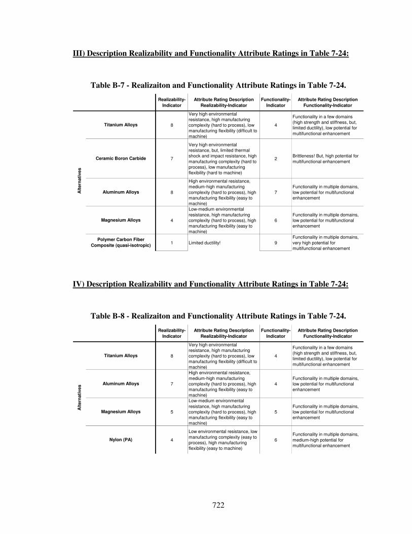
722
III) Description Realizability and Functionality Attribute Ratings in Table 7-24:
Table B-7 - Realizaiton and Functionality Attribute Ratings in Table 7-24.
Realizability-
Indicator
Attribute Rating Description
Realizability-Indicator
Functionality-
Indicator
Attribute Rating Description
Functionality-Indicator
8
Very high environmental
resistance, high manufacturing
complexity (hard to process), low
manufacturing flexibility (difficult to
machine)
4
Functionality in a few domains
(high strength and stiffness, but,
limited ductility), low potential for
multifunctional enhancement
7
Very high environmental
resistance, but, limited thermal
shock and impact resistance, high
manufacturing complexity (hard to
process), low manufacturing
flexibility (hard to machine)
2Brittleness! But, high potential for
multifunctional enhancement
8
High environmental resistance,
medium-high manufacturing
complexity (hard to process), high
manufacturing flexibility (easy to
machine)
7
Functionality in multiple domains,
low potential for multifunctional
enhancement
4
Low-medium environmental
resistance, high manufacturing
complexity (hard to process), high
manufacturing flexibility (easy to
machine)
6
Functionality in multiple domains,
low potential for multifunctional
enhancement
1 Limited ductility! 9
Functionality in multiple domains,
very high potential for
multifunctional enhancement
Ceramic Boron Carbide
Alt
ern
ati
ves
Titanium Alloys
Aluminum Alloys
Magnesium Alloys
Polymer Carbon Fiber
Composite (quasi-isotropic)
IV) Description Realizability and Functionality Attribute Ratings in Table 7-24:
Table B-8 - Realizaiton and Functionality Attribute Ratings in Table 7-24.
Realizability-
Indicator
Attribute Rating Description
Realizability-Indicator
Functionality-
Indicator
Attribute Rating Description
Functionality-Indicator
8
Very high environmental
resistance, high manufacturing
complexity (hard to process), low
manufacturing flexibility (difficult to
machine)
4
Functionality in a few domains
(high strength and stiffness, but,
limited ductility), low potential for
multifunctional enhancement
7
High environmental resistance,
medium-high manufacturing
complexity (hard to process), high
manufacturing flexibility (easy to
machine)
4
Functionality in multiple domains,
low potential for multifunctional
enhancement
5
Low-medium environmental
resistance, high manufacturing
complexity (hard to process), high
manufacturing flexibility (easy to
machine)
5
Functionality in multiple domains,
low potential for multifunctional
enhancement
4
Low environmental resistance, low
manufacturing complexity (easy to
process), high manufacturing
flexibility (easy to machine)
6
Functionality in multiple domains,
medium-high potential for
multifunctional enhancement
Alt
ern
ati
ves
Titanium Alloys
Aluminum Alloys
Magnesium Alloys
Nylon (PA)
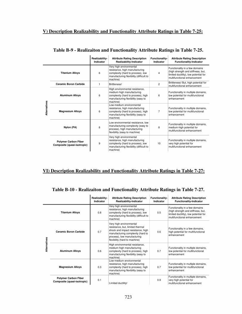
723
V) Description Realizability and Functionality Attribute Ratings in Table 7-25:
Table B-9 - Realizaiton and Functionality Attribute Ratings in Table 7-25.
Realizability-
Indicator
Attribute Rating Description
Realizability-Indicator
Functionality-
Indicator
Attribute Rating Description
Functionality-Indicator
6
Very high environmental
resistance, high manufacturing
complexity (hard to process), low
manufacturing flexibility (difficult to
machine)
4
Functionality in a few domains
(high strength and stiffness, but,
limited ductility), low potential for
multifunctional enhancement
1 Brittleness! 2Brittleness! But, high potential for
multifunctional enhancement
6
High environmental resistance,
medium-high manufacturing
complexity (hard to process), high
manufacturing flexibility (easy to
machine)
6
Functionality in multiple domains,
low potential for multifunctional
enhancement
6
Low-medium environmental
resistance, high manufacturing
complexity (hard to process), high
manufacturing flexibility (easy to
machine)
7
Functionality in multiple domains,
low potential for multifunctional
enhancement
8
Low environmental resistance, low
manufacturing complexity (easy to
process), high manufacturing
flexibility (easy to machine)
8
Functionality in multiple domains,
medium-high potential for
multifunctional enhancement
9
Very high environmental
resistance, high manufacturing
complexity (hard to process), low
manufacturing flexibility (difficult to
machine)
10
Functionality in multiple domains,
very high potential for
multifunctional enhancement
Alt
ern
ati
ves
Titanium Alloys
Aluminum Alloys
Magnesium Alloys
Polymer Carbon Fiber
Composite (quasi-isotropic)
Ceramic Boron Carbide
Nylon (PA)
VI) Description Realizability and Functionality Attribute Ratings in Table 7-27:
Table B-10 - Realizaiton and Functionality Attribute Ratings in Table 7-27.
Realizability-
Indicator
Attribute Rating Description
Realizability-Indicator
Functionality-
Indicator
Attribute Rating Description
Functionality-Indicator
0.8
Very high environmental
resistance, high manufacturing
complexity (hard to process), low
manufacturing flexibility (difficult to
machine)
0.5
Functionality in a few domains
(high strength and stiffness, but,
limited ductility), low potential for
multifunctional enhancement
0.7
Very high environmental
resistance, but, limited thermal
shock and impact resistance, high
manufacturing complexity (hard to
process), low manufacturing
flexibility (hard to machine)
0.6
Functionality in a few domains,
high potential for multifunctional
enhancement
0.6
High environmental resistance,
medium-high manufacturing
complexity (hard to process), high
manufacturing flexibility (easy to
machine)
0.7
Functionality in multiple domains,
low potential for multifunctional
enhancement
0.3
Low-medium environmental
resistance, high manufacturing
complexity (hard to process), high
manufacturing flexibility (easy to
machine)
0.7
Functionality in multiple domains,
low potential for multifunctional
enhancement
0.1
Limited ductility!
0.9
Functionality in multiple domains,
very high potential for
multifunctional enhancement
Titanium Alloys
Ceramic Boron Carbide
Aluminum Alloys
Magnesium Alloys
Alt
ern
ati
ves
Polymer Carbon Fiber
Composite (quasi-isotropic)
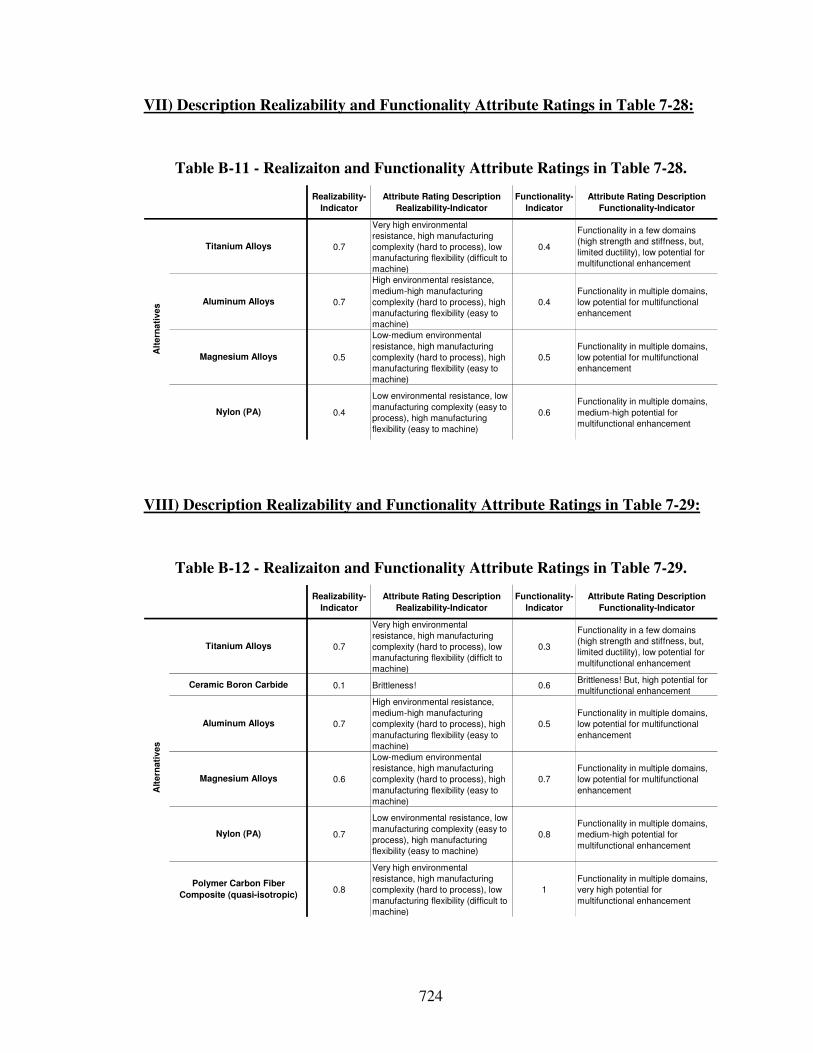
724
VII) Description Realizability and Functionality Attribute Ratings in Table 7-28:
Table B-11 - Realizaiton and Functionality Attribute Ratings in Table 7-28.
Realizability-
Indicator
Attribute Rating Description
Realizability-Indicator
Functionality-
Indicator
Attribute Rating Description
Functionality-Indicator
0.7
Very high environmental
resistance, high manufacturing
complexity (hard to process), low
manufacturing flexibility (difficult to
machine)
0.4
Functionality in a few domains
(high strength and stiffness, but,
limited ductility), low potential for
multifunctional enhancement
0.7
High environmental resistance,
medium-high manufacturing
complexity (hard to process), high
manufacturing flexibility (easy to
machine)
0.4
Functionality in multiple domains,
low potential for multifunctional
enhancement
0.5
Low-medium environmental
resistance, high manufacturing
complexity (hard to process), high
manufacturing flexibility (easy to
machine)
0.5
Functionality in multiple domains,
low potential for multifunctional
enhancement
0.4
Low environmental resistance, low
manufacturing complexity (easy to
process), high manufacturing
flexibility (easy to machine)
0.6
Functionality in multiple domains,
medium-high potential for
multifunctional enhancement
Alt
ern
ati
ves
Titanium Alloys
Aluminum Alloys
Magnesium Alloys
Nylon (PA)
VIII) Description Realizability and Functionality Attribute Ratings in Table 7-29:
Table B-12 - Realizaiton and Functionality Attribute Ratings in Table 7-29.
Realizability-
Indicator
Attribute Rating Description
Realizability-Indicator
Functionality-
Indicator
Attribute Rating Description
Functionality-Indicator
0.7
Very high environmental
resistance, high manufacturing
complexity (hard to process), low
manufacturing flexibility (difficlt to
machine)
0.3
Functionality in a few domains
(high strength and stiffness, but,
limited ductility), low potential for
multifunctional enhancement
0.1 Brittleness! 0.6Brittleness! But, high potential for
multifunctional enhancement
0.7
High environmental resistance,
medium-high manufacturing
complexity (hard to process), high
manufacturing flexibility (easy to
machine)
0.5
Functionality in multiple domains,
low potential for multifunctional
enhancement
0.6
Low-medium environmental
resistance, high manufacturing
complexity (hard to process), high
manufacturing flexibility (easy to
machine)
0.7
Functionality in multiple domains,
low potential for multifunctional
enhancement
0.7
Low environmental resistance, low
manufacturing complexity (easy to
process), high manufacturing
flexibility (easy to machine)
0.8
Functionality in multiple domains,
medium-high potential for
multifunctional enhancement
0.8
Very high environmental
resistance, high manufacturing
complexity (hard to process), low
manufacturing flexibility (difficult to
machine)
1
Functionality in multiple domains,
very high potential for
multifunctional enhancement
Titanium Alloys
Ceramic Boron Carbide
Aluminum Alloys
Magnesium Alloys
Alt
ern
ati
ves
Nylon (PA)
Polymer Carbon Fiber
Composite (quasi-isotropic)
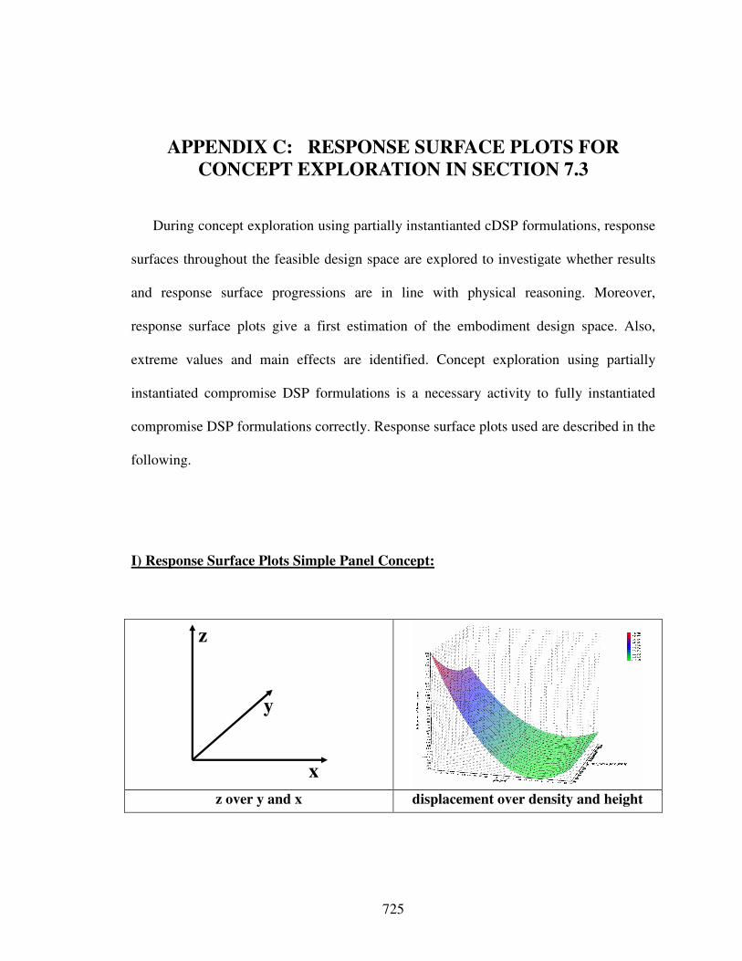
725
APPENDIX C: RESPONSE SURFACE PLOTS FOR
CONCEPT EXPLORATION IN SECTION 7.3
During concept exploration using partially instantianted cDSP formulations, response
surfaces throughout the feasible design space are explored to investigate whether results
and response surface progressions are in line with physical reasoning. Moreover,
response surface plots give a first estimation of the embodiment design space. Also,
extreme values and main effects are identified. Concept exploration using partially
instantiated compromise DSP formulations is a necessary activity to fully instantiated
compromise DSP formulations correctly. Response surface plots used are described in the
following.
I) Response Surface Plots Simple Panel Concept:
x
y
z
z over y and x displacement over density and height
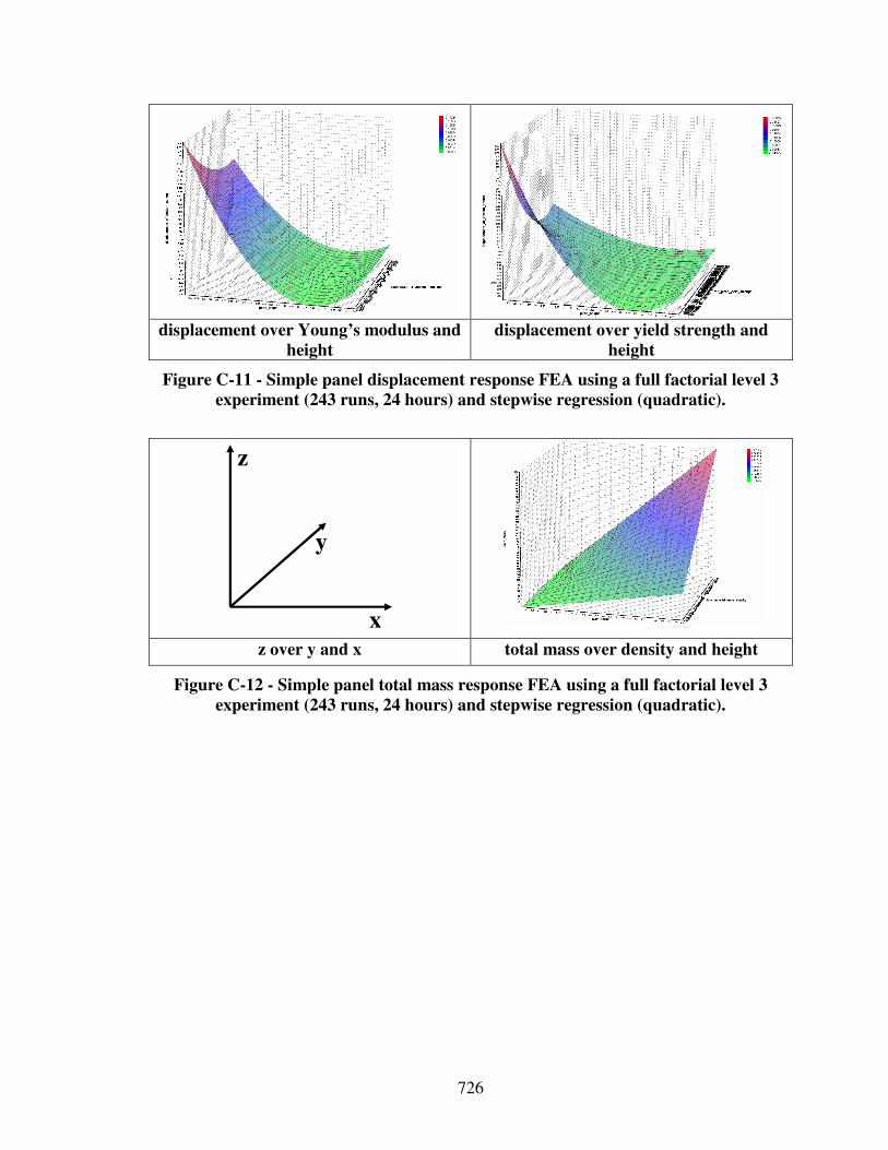
726
displacement over Young’s modulus and
height displacement over yield strength and
height
Figure C-11 - Simple panel displacement response FEA using a full factorial level 3
experiment (243 runs, 24 hours) and stepwise regression (quadratic).
x
y
z
z over y and x total mass over density and height
Figure C-12 - Simple panel total mass response FEA using a full factorial level 3
experiment (243 runs, 24 hours) and stepwise regression (quadratic).
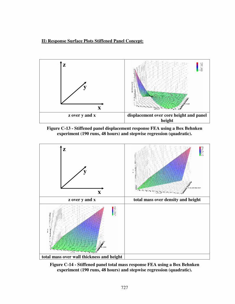
727
II) Response Surface Plots Stiffened Panel Concept:
x
y
z
z over y and x displacement over core height and panel
height
Figure C-13 - Stiffened panel displacement response FEA using a Box Behnken
experiment (190 runs, 48 hours) and stepwise regression (quadratic).
x
y
z
z over y and x total mass over density and height
total mass over wall thickness and height
Figure C-14 - Stiffened panel total mass response FEA using a Box Behnken
experiment (190 runs, 48 hours) and stepwise regression (quadratic).
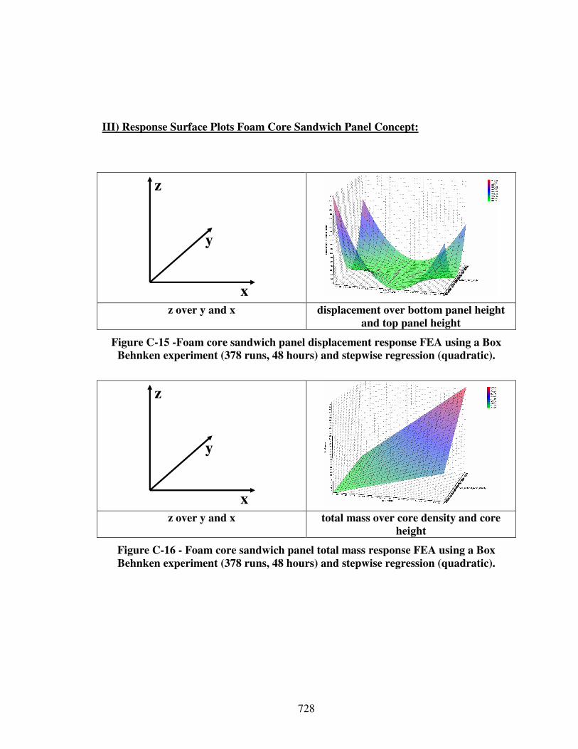
728
III) Response Surface Plots Foam Core Sandwich Panel Concept:
x
y
z
z over y and x displacement over bottom panel height
and top panel height
Figure C-15 -Foam core sandwich panel displacement response FEA using a Box
Behnken experiment (378 runs, 48 hours) and stepwise regression (quadratic).
x
y
z
z over y and x total mass over core density and core
height
Figure C-16 - Foam core sandwich panel total mass response FEA using a Box
Behnken experiment (378 runs, 48 hours) and stepwise regression (quadratic).
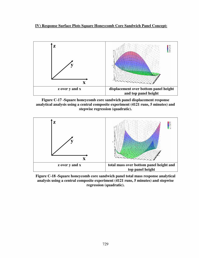
729
IV) Response Surface Plots Square Honeycomb Core Sandwich Panel Concept:
x
y
z
z over y and x displacement over bottom panel height
and top panel height
Figure C-17 -Square honeycomb core sandwich panel displacement response
analytical analysis using a central composite experiment (4121 runs, 5 minutes) and
stepwise regression (quadratic).
x
y
z
z over y and x total mass over bottom panel height and
top panel height
Figure C-18 -Square honeycomb core sandwich panel total mass response analytical
analysis using a central composite experiment (4121 runs, 5 minutes) and stepwise
regression (quadratic).
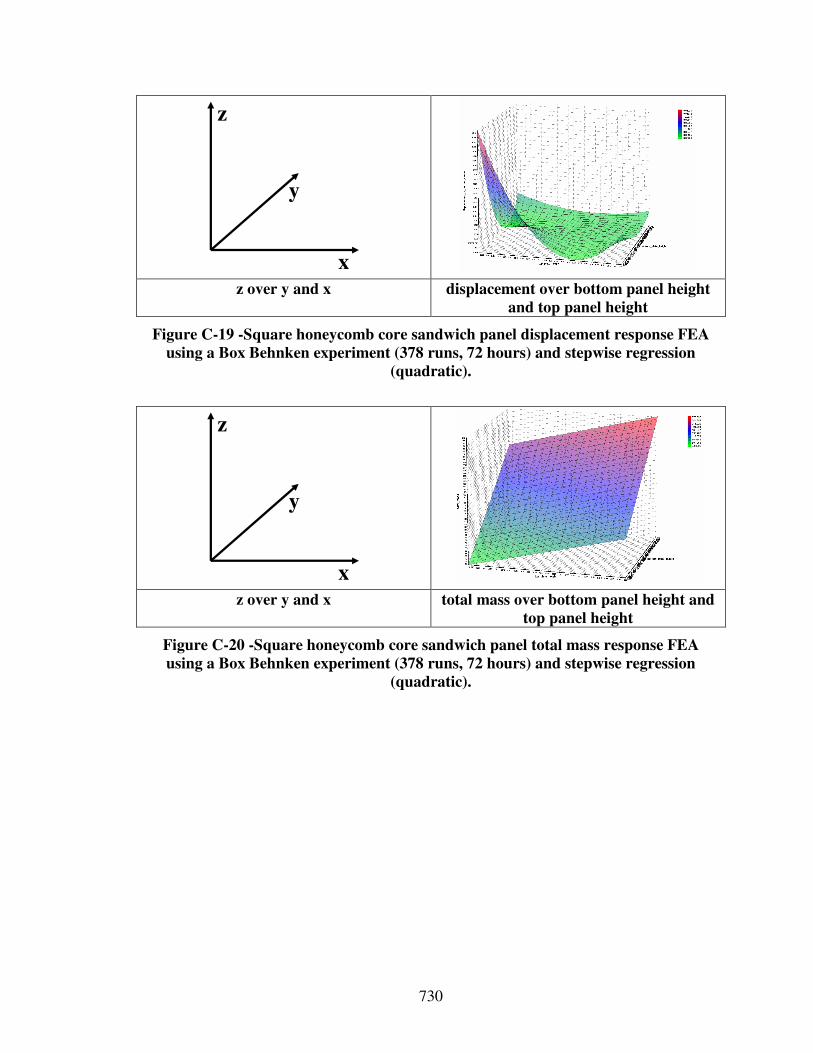
730
x
y
z
z over y and x displacement over bottom panel height
and top panel height
Figure C-19 -Square honeycomb core sandwich panel displacement response FEA
using a Box Behnken experiment (378 runs, 72 hours) and stepwise regression
(quadratic).
x
y
z
z over y and x total mass over bottom panel height and
top panel height
Figure C-20 -Square honeycomb core sandwich panel total mass response FEA
using a Box Behnken experiment (378 runs, 72 hours) and stepwise regression
(quadratic).
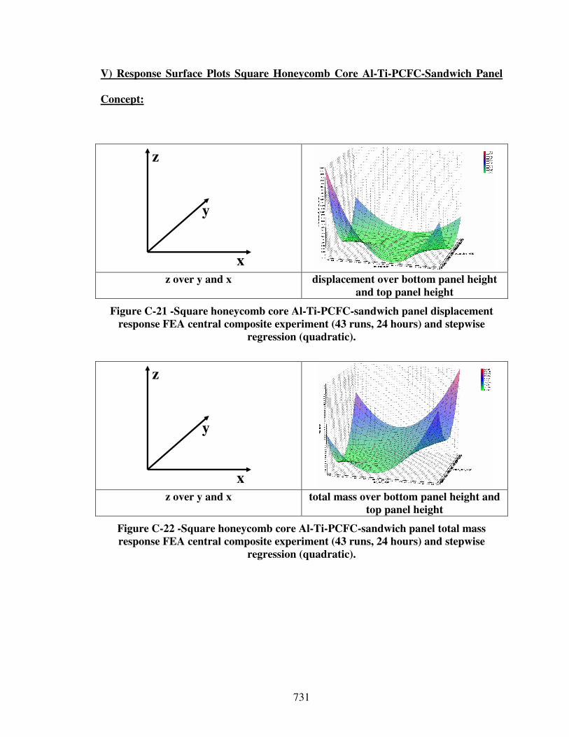
731
V) Response Surface Plots Square Honeycomb Core Al-Ti-PCFC-Sandwich Panel
Concept:
x
y
z
z over y and x displacement over bottom panel height
and top panel height
Figure C-21 -Square honeycomb core Al-Ti-PCFC-sandwich panel displacement
response FEA central composite experiment (43 runs, 24 hours) and stepwise
regression (quadratic).
x
y
z
z over y and x total mass over bottom panel height and
top panel height
Figure C-22 -Square honeycomb core Al-Ti-PCFC-sandwich panel total mass
response FEA central composite experiment (43 runs, 24 hours) and stepwise
regression (quadratic).
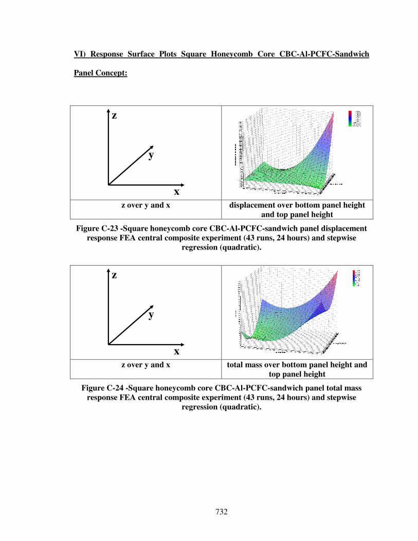
732
VI) Response Surface Plots Square Honeycomb Core CBC-Al-PCFC-Sandwich
Panel Concept:
x
y
z
z over y and x displacement over bottom panel height
and top panel height
Figure C-23 -Square honeycomb core CBC-Al-PCFC-sandwich panel displacement
response FEA central composite experiment (43 runs, 24 hours) and stepwise
regression (quadratic).
x
y
z
z over y and x total mass over bottom panel height and
top panel height
Figure C-24 -Square honeycomb core CBC-Al-PCFC-sandwich panel total mass
response FEA central composite experiment (43 runs, 24 hours) and stepwise
regression (quadratic).
733
REFERENCES
[1] Phase Changing Materials in Textiles. [cited 10/19/2007]; Available from: http://www.backcountry outlet.com/outlet/BUR0920/Burton-Ronin-Transition-
JacketMens.html?CMP_ID=SH_MSN002&CMP_SKU=BUR0920&mv_pc=r108.
[2] Heat Chairs. [cited 10/18/2007]; Available from: http://www.udeducation.org/
teach/course_mods/donnelly2.asp.
[3] Phase Changing Materials in Glasses Frames. [cited 10.18.2007]; Available from: http://www.mrsec.wisc.edu/Edetc/cineplex/NiTi/.
[4] Early Experiments in Transportation. [cited 10/18/2007]; Available from: http://www.office-humour. co.uk/cartoons/2604/.
[5] Morphing Structures. [cited 10/18/2007]; Available from: http://www.nasa.gov.
[6] Wikipedia - the Free Encyclopedia. 2004 [cited; Available from: http://en.wikipedia.org/wiki/Main_Page.
[7] Abramowicz, W. and T. Wierzbicke, 1988, "Axial Crushing of Foam-Filled Columns," International Journal of Mechanical Sciences. Vol. 30, pp. 263-271.
[8] Abramowicz, W. and N. Jones, 1989, "Dynamic Axial Crushing of Square Tubes," International Journal of Impact Engineering. Vol. 56, No. 1, pp. 113-120.
[9] Abramowicz, W. and T. Wierzbicki, 1989, "Axial Crushing of Multicorner Sheet Metal Columns," Journal of Applied Mechanics. Vol. 57, No. 3, pp. 101-114.
[10] Ackerman, J., 1993, Robust Control: Systems with Uncertain Physical
Parameters. Springer-Verlag, Berlin.
[11] Adams, B.L., M. Lyon, B. Henrie, S.R. Kalidindi and H. Garmestani, 2002, "Spectral Integration of Microstructure and Design," Materials Science Forum. Vol. 408-412, pp. 493-498.
[12] Adams, J.L., 2001, Conceptual Blockbusting. Perseus Publishing, Cambridge, MA.
[13] Agogino, A.M., 1997, "Information in the Design Process,” in Frontiers of
Engineering: Reports on Leading Edge Engineering from the 1996 NAE Symposium on Frontiers of Engineering. National Academy of Engineering, pp. 13-16.
734
[14] Ahaeri, A.Y., D.J. Weidner and J.B. Parise, 1992, "Elasticity of a-Cristoabilit: A Silicon Dioxide with a Negative Poisson's Ratio," Science. Vol. 257, pp. 650-652.
[15] Ahmed, S. and K.M. Wallace. 2004, "Reusing Design Knowledge." In 14th CIRP
Design Seminar. Cairo, Egypt, pp. 82-96.
[16] Akexandrow, N., J.E.J. Dennis, R.M. Lewis and V. Torczon, 1998, "A Trust Region Framework for Managing the Use of Approximation Models in Optimization," Structural Optimization. Vol. 15, No. 1, pp. 16-23.
[17] Alderson, K.L., A. Alderson and K.E. Evans, 1996, "The Interpretation of the Strain-Dependent Poisson's Ratio in Auxetic Polyethylene " Journal of Strain
Analysis. Vol. 32, No. 3, pp. 201-212.
[18] Alderson, K.L., V.R. Simkins, P.J. Coenen, A. Davies, A. Alderson and K.E. Evans, 2005, "How to Make Auxetic Fiber Reinforced Composites," Physica
Status Solidi (b). Vol. 242, No. 3, pp. 509-518.
[19] Alexopoulos, K., N. Papkostas, D. Mourtzis, P. Gogos and G. Chryssolouris, 2007, "Quantifying the Flexibility of a Manufacturing System by Applying the Transfer Function," International Journal of Computer Integrated Manufacturing. Vol. 20, No. 6, pp. 538-547.
[20] Almgren, R.F., 1985, "An Isotropic Three-Dimensional Structure with Poisson's Ratio = - 1," Journal of Elasticity. Vol. 15, pp. 427-430.
[21] Altshuller, G.S., 1984, Creativity as an Exact Science. Gordon and Breach Science Publishers, London.
[22] Altshuller, G.S., 1996, And Suddenly the Inventor Appeared. Technical Innovation Center Inc., Worcester, MA.
[23] Anderson, D.M., 1997, Agile Product Development for Mass Customization. Irwin, Chicago, IL.
[24] Andrews, K.R.F., G.L. England and E. Ghani, 1983, "Classification of the Axial Collapse of Cylindrical Tubes under Quasi-Static Loading," International Journal
of Mechanical Sciences. Vol. 25, pp. 687-696.
[25] Anthony, L., W.C. Regli, J.E. Jon and L.V. Santiago, 2001, "An Approach to Capturing Structure, Behavior and Function of Artifacts in CAD," Journal of
Computing and Information Science in Engineering. Vol. 1, No. 2, pp. 186-192.
[26] Aouni, B., F.B. Abdelaziz and J.-M. Martel, 2005, "Decision-Maker's Preferences Modeling in the Stochastic Goal Programming," European Journal of
Operational Research. Vol. 162, pp. 610-618.
[27] Arora, J.S., 1989, Introduction to Optimum Design. McGraw-Hill, New York, NY.
735
[28] Ashby, M. and K. Johnson, 2002, Materials and Design: The Art and Science of
Material Selection in Product Design. Butterworth-Heinemann, Boston, MA.
[29] Ashby, M.F., 1999, Materials Selection in Mechanical Design. Butterworth-Heinemann, Oxford, UK.
[30] Ashby, M.F., A.G. Evans, N.A. Fleck, L.J. Gibson, J.W. Hutchinson and H.N.G. Wadley, 2000, Metal Foams: A Design Guide. Butterworth-Heinemann, Boston, MA.
[31] Atkins, A.G., 1987, "Scaling in Combined Plastic Flow and Fracture," International Journal of Mechanical Sciences. Vol. 29, pp. 115-121.
[32] Aughenbaugh, J.M., J. Ling and C.J.J. Paredis. 2005, "The Use of Imprecise Probabilities to Estimate the Value of Information in Design." In 2005 ASME
International Mechanical Engineering Congress and RD&D Expo. Orlando, FL, USA: ASME, Paper Number: IMECE2005-81181.
[33] Aughenbaugh, J.M. and C.J.J. Paredis. 2006, "The Value of Using Imprecise Probabilities in Engineering Design." Journal of Mechanical Design, 128(4), 969-79.
[34] Aughenbaugh, J.M. and C.J.J. Paredis. 2005, "The Value of Using Imprecise Probabilities in Engineering Design." In ASME 2005 Design Engineering
Technical Conferences and Computers and Information in Engineering
Conference. Long Beach, CA, USA: ASME, Paper Number: DETC2005-85354.
[35] Aughenbaugh, J.M., 2006, Managing Uncertainty in Engineering Design Using
Imprecise Probabilities and Principles of Information Economics, PhD Dissertation, The G.W. Woodruff School of Mechanical Engineering, Georgia Institute of Technology, Atlanta, GA, U.S.A.
[36] Austin, R., 2005, Numerical Simulation of the Shock Compaction of Microscale
Reactive Particle Systems, MS Thesis, The G.W. Woodruff School of Mechanical Engineering, Georgia Institute of Technology, Atlanta.
[37] Bacon, G., S. Beckman, D. Mowery and E. Wilson, 1994, "Managing Product Definition in High Technology Industries: A Pilot Study," California
Management Review. Vol. 36, pp. 32-56.
[38] Badhrinath, K. and S.S. Rao, 1996, "Modeling for Concurrent Design Using Game Theory Formulations," Concurrent Engineering: Research and
Applications. Vol. 4, No. 4, pp. 389-399.
[39] Bakr, M.H., J.W. Bandler, K. Madsen and J. Sendergaard, 2000, "Review of the Space Mapping Approach to Engineering Optimization and Modeling," Optimization and Engineering. Vol. 1, No. 241-276.
736
[40] Bandler, J., Q. Cheng, S. Dakroury, A. Mohamed, M. Bakr, K. Madsen and J. Sndergaard, 2004, "Space Mapping: The State of the Art," IEEE Transactions
Microwave Theory Technology. Vol. 52, pp. 337-361.
[41] Bar-Yam, Y., 1997, Dynamics of Complex Systems. Westview Press, Colorado, CO.
[42] Bar-Yam, Y., 2004, "A Mathematical Theory of Strong Emergence Using Multiscale Variety," Journal of Complexity. Vol. 9, No. 6, pp. 15-24.
[43] Bar-Yam, Y., 2004, Making Things Work. NECSI Knowledge Press, Brookline, MA.
[44] Barclay, P., K. Srinivasan, M. Borselli and O. Painter, 2004, "Efficient Input and Output Fiber Coupling to a Photonic Crystal Waveguide," Optics Letters. Vol. 29, No. 7, pp. 697-699.
[45] Bascaran, E., R.B. Bannerot and F. Mistree. 1987, "The Conceptual Development of a Methodology for Solving Multi-Objective Hierarchical Thermal Design Problems." In ASME National Heat Transfer Conference. Pittsburgh, PA: ASME, Paper Number: 87-HT-62.
[46] Bascaran, E., R.B. Bannerot and F. Mistree, 1989, "Hierarchical Selection Decision Support Problems in Conceptual Design," Engineering Optimization. Vol. 14, pp. 207-238.
[47] Baxter, J.E., N.P. Juster and A. De Pennington, 1994, "A Functional Data Model for Assemblies Used to Verify Product Design Specifications," Journal of
Engineering Manufacture. Vol. 28, pp. 235-244.
[48] Bayindir, M., B. Temelkuran and E. Ozbar, 2000, "Photonic-Crystal Based Beam Splitter," Applied Physics Letters. Vol. 77, pp. 3902-3904.
[49] Beach, R., A.P. Muhlemann, D.H.R. Price, A. Paterson and J.A. Sharp, 2000, "A Review of Manufacturing Flexibility," European Journal of Operational
Research. Vol. 122, pp. 41-57.
[50] Beer, R.D. [cited 12.13.2007]; Available from: http://dutnsic.tn.tudelft.nl:8080/
main/node41.html#sect_minimax.
[51] Beitz, W., 1970, "Systemtechnik in Der Konstruktion," DIN Mitteilungen. Vol. 49, pp. 295-302.
[52] Beitz, W., 1971, "Systemtechnik Im Ingenieurbereich," VDI Berichte. Vol. 174.
[53] Beitz, W., 1985, "Kreativität Des Konstrukteurs," Konstruktion. Vol. 37, pp. 381-386.
737
[54] Belytschko, T., J. Fish, T.R.J. Hughes and T. Oden, Simulation Based
Engineering Science: A Report on a Workshop. National Science Foundation, 2004.
[55] Ben-Tal, A. and A. Nemirovski, 1998, "Robust Convex Optimization," Mathematics of Operations Research. Vol. 23, pp. 769-805.
[56] Benami, O. and Y. Jin. 2002, "Creative Stimulation in Conceptual Design." In
ASME Design Engineering Technical Conferences. Montreal, Canada: ASME, Paper Number: DETC2002-34023.
[57] Berliner, C. and J.A. Brimson, 1988, Cost Management for Today's Advanced
Manufacturing: The Cam-1 Conceptual Design. Harvard Business School Press, Boston, MA.
[58] Bettonvil, B., 1990, Detection of Important Factors by Sequential Bifurcation. Tilburg University Press, Tilburg.
[59] Bettonvil, B. and J.J.C. Kleijnen, 1996, "Searching for Important Factors in Simulation Models with Many Factors: Sequential Bifurcation," European
Journal of Operational Research. Vol. 96, No. 1, pp. 180-194.
[60] Bienstman, P. and R. Baets, 2001, "Optical Modeling of Photonic Crystals and Vcsels Using Eigenmode Expansion and Perfectly Matched Layers," Optical and
Quantum Electronics. Vol. 33, pp. 327-341.
[61] Bienstman, P. and R. Baets, 2002, "Rigorous and Efficient Optical Vcsel Model Based on Vectorial Eigenmode Expansion and Perfectly Matched Layers," IEE-
Optoelectron. Proc. Vol. 149, pp. 161-165.
[62] Bienstman, P., S. Assefa, S.G. Johnson, J.D. Joannopoulos, G. Petrich and L. Kolodziejski, 2003, "Taper Structures for Coupling into Photonic Crystal Slab Waveguides," Optical Physics. Vol. 20, No. 9, pp. 1817-1821.
[63] Birch, R.S. and N. Jones, 1990, "Dynamic and Static Axial Crushing of Axially Stiffened Cylindrical Shells," Thin-Walled Structures. Vol. 9, pp. 29-60.
[64] Blass, E., 1981, "Verfahren Mit Systemtechnik Entwickelt," VDI Nachrichten. Vol. 29, pp. 34-42.
[65] Bloebaum, C.L., P. Hajela and J. Sobieszczanski-Sobieski, 1992, "Non-Hierarchic System Decomposition in Structural Optimization," Engineering Optimization. Vol. 19, pp. 171-186.
[66] Bloebaum, C.L., 1995, "Coupling Strength-Based System Reduction for Complex Engineering Design," Structural Optimization. Vol. 10, No. 2, pp. 113-121.
738
[67] Borel, P.I., A. Harpoth, L.H. Frandsen and M. Kristensen, 2004, "Topology Optimization and Fabrication of Photonic Crystal Structures," Optics Express. Vol. 12, No. 9, pp. 1996-2001.
[68] Bornengo, D., F. Scarpa and C. Remillat, 2005, "Evaluation of Hexagonal Chiral Structure for Morphing Airfoil Concept," Journal of Aerospace Engineering. Vol. 219, pp. 185-192.
[69] Box, G.E.P. and K.B. Wilson, 1951, "On the Experimental Attainment of Optimum Conditions," Journal of the Royal Statistical Society - Series B, No. 13, pp. 1-45.
[70] Box, G.E.P. and D.W. Behnken, 1960, "Some New Three Level Designs for the Study of Quantitative Variables," Technometrics. Vol. 2, pp. 455-475.
[71] Box, G.E.P. and N.R. Draper, 1969, Evolutionary Operation: A Statistical Method
for Process Management. John Wiley and Sons, New York, NY.
[72] Box, G.E.P., 1979, "Robustness in The Strategy of Scientific Model Building,” in Robustness in Statistics, R.L. Launer and G.N. Wiklinson, Editors. Academic Press: New York, NY, pp. 201-236.
[73] Box, G.E.P., J.S. Hunter and W.G. Hunter, 2005, Statistics for Experimenters:
Design, Innovation, and Discovery. Wiley, New York, NY.
[74] Bracewell, R.H. and J.E.E. Sharpe, 1996, "Functional Descriptions Used in Computer Support for Qualitative Scheme Generation - Schemebuilder," Artificial
Intelligence for Engineering Design, Analysis, and Manufacturing. Vol. 10, No. 5, pp. 333-345.
[75] Bradley, S.R. and A.M. Agogino, 1994, "An Intelligent Real Time Design Methodology for Component Selection: An Approach to Managing Uncertainty," Journal of Mechanical Design. Vol. 116, pp. 980-988.
[76] Bradley, S.R., A.M. Agogino and W.H. Wood, 1994, "Intelligent Engineering Component Catalogs,” in Artificial Intelligence in Design' 94. Kluwer: Dordrecht, The Netherlands, pp. 641-658.
[77] Braha, D. and O. Maimon, 1997, "The Design Process: Properties, Paradigms, and Structure," IEEE Transactions on Systems, Man, and Cybernetics - Part A:
Systems and Humans. Vol. 27, No. 2, pp. 146-166.
[78] Bras, B.A. and F. Mistree, 1991, "Designing Design Process in Decision-Based Concurrent Engineering," SAE Transactions, Journal of Materials and
Manufacturing. Vol. 100, pp. 451-458.
[79] Bras, B.A., 1992, "Foundations for Designing Decision-Based Design
Processes," PhD Dissertation, University of Houston, Houston, Texas.
739
[80] Bras, B.A. 1992, "Designing Design Processes for Decision-Based Concurrent Engineering." In CERC's First Workshop on Product Development, Process
Modeling and Characterization. Morgantown, West-Virginia: Concurrent Engineering Research Center, pp. 7-9.
[81] Breuer, O. and U. Sundararaj, 2004, "Big Returns from Small Fibers: A Review of Polumer/Carbon Nanotube Composites," Polymer Composites. Vol. 25, No. 6, pp. 630-647.
[82] Budiansky, B., 1999, "On the Minimum Weights of Compression Structures," International Journal of Solids and Structures. Vol. 36, pp. 3677-3708.
[83] Buechel, A., 1969, "Inudstrielle Organisation," Systems Engineering. Vol. 38, pp. 373-385.
[84] Buede, D.M., 1999, The Engineering Design of Systems: Models and Methods. Wiley-Interscience, New York, NY.
[85] Cagan, J. and C.M. Vogel. 2002, Creating Breakthrough Products: Innovation
from Product Planning to Program Approval. Financial Times Prentice Hall, Upper Saddle River, NJ.
[86] Cagan, J. and C.M. Vogel. 2002, "First-Order Necessary Conditions for Robust Optimality." In ASME Advances in Design Automation. Albuquerque, NM, Vol. 42, pp. 539-549.
[87] Calladine, C.R., 1986, "Analysis of Large Plastic Deformations in Shell Structures,” in Inelasitc Behavior of Plates and Shells, Iutam Symposium, L. Bevilacqua, R. Feijoo and R. Valid, Editors. Springer: Berlin, pp. 69-101.
[88] Calvano, C.N. and P. John, 2004, "Systems Engineering in an Age of Complexity," Systems Engineering. Vol. 7, No. 1, pp. 25-34.
[89] Campbell, M., J. Cagan and K. Kotovsky, 1999, "A-Design: An Agent Based Approach to Conceptual Design in a Dynamic Environment," Research in
Engineering Design. Vol. 11, pp. 172-192.
[90] Campbell, M., J. Cagan and K. Kotovsky, 1998, "Agent-based Synthesis of Electro-Mechanical Design Configurations," Proceedings of the 1998 ASME
Design Engineering Technical Conferences and Computers in Engineering
Conference: Design Theory and Methodology Conference. Atlanta, GA: ASME, Paper Number: DETC98 -5673.
[91] Campbell, M., J. Cagan and K. Kotovsky, 2000, "Agent-Based Synthesis of Electromechanical Design Configurations," ASME Journal of Mechanical Design. Vol. 122, pp. 1-9.
740
[92] Campbell, M.I., J. Cagan and K. Kotovsky, 2003, "The a-Design Approach to Managing Automated Design Synthesis," Research in Engineering Design. Vol. 14, pp. 12-24.
[93] Carlos, S., K. Madhavan, G. Gupta, D. Keese, U. Maheshwaraa and C.C. Seepersad. 2006, "Development and Application of a Flexibility-Based Method for Multi-Scale Design." In 11th AIAA/ISSMO Multidisciplinary Analysis and
Optimization Conference. Portsmouth, Virginia: AIAA, Paper Number: AIAA2006-7063.
[94] Carney, I.J.F. and J.R. Veillette, 1984, "Impact Response and Energy Characteristics of Stiffened Metallic Tubes,” in Structural Impact and
Crashworthiness, G. Davies and J. Morton, Editors. Elsevier: New York, NY, pp. 564-575.
[95] Carney, I.J.F. and S. Pothen, 1988, "Energy Dissipation in Braced Cylindrical Shells," International Journal of Mechanical Sciences. Vol. 30, pp. 203-216.
[96] Chakrabarti, A. and T.P. Bligh, 1994, "An Approach to Functional Synthesis of Solutions in Mechanical Conceptual Design. Part 1: Introduction and Knowledge Representation," Research in Engineering Design. Vol. 6, pp. 127-141.
[97] Chakrabarti, A. and T. Bligh, 1996, "An Approach to Functional Synthesis of Solutions in Mechanical Conceptual Design. Part 2: Kind Synthesis," Research in Engineering Design. Vol. 8, pp. 52-62.
[98] Chakrabarti, A. and T. Bligh, 1996, "An Approach to Functional Synthesis of Solutions in Mechanical Conceptual Design. Part 3: Kind Synthesis," Research in
Engineering Design. Vol. 8, pp. 116-124.
[99] Chakrabarti, A. 1998, "Supporting Two Views of Function in Mechanical Design." In Proceedings of the 5th Artificial Intelligence in Design Conference: Kluwer Academic Publishers, Dordrecht, The Netherlands, pp. 311-325.
[100] Chakrabarti, A. and T.P. Bligh, 2001, "A Scheme for Functional Reasoning in Conceptual Design," Design Studies. Vol. 22, No. 493-517.
[101] Chanron, V. and K. Lewis. 2003, "A Study of Convergence in Decentralized
Design." In ASME Design Automation Conference. Chicago, IL: ASME, Paper Number: DETC2003-48782.
[102] Chanron, V., T. Singh and K. Lewis. 2004, "An Investigation of Equilibrium Stability in Decentralized Design Using Nonlinear Control Theory.” In 10th
AIAA/ISSMO Multidisciplinary Analysis and Optimization Conference. Albany, NY, USA. Paper Number: AIAA2004-4600.
[103] Chanron, V.K., K. Lewis, Y. Musrase, K. Izui, S. Nishiwaki and M. Yoshimura. 2005, "Handling Multiple Objectives in Decentralized Design.” In International
741
Design Engineering Technical Conferences - Advances in Design Automation. Long Beach, CA: ASME, Paper Number: DETC2005-84807.
[104] Chen, L.-C. and L. Lin, 2002, "Optimization of Product Configuration Design Using Functional Requirements and Constraints," Research in Engineering Design. Vol. 13, pp. 167-182.
[105] Chen, L. and S. Li, 2002, "A Computerized Team Approach for Concurrent Product and Process Design Optimization," Computer Aided Design. Vol. 34, No. 1, pp. 57-69.
[106] Chen, L., Z. Ding and S. Li, 2005, "A Formal Two-Phase Method for Decomposition of Complex Design Problems," Journal of Mechanical Design. Vol. 127, No. 2, pp. 184-195.
[107] Chen, L., Z. Ding and S. Li, 2005, "Tree-Based Dependency Analysis in Decomposition and Re-Decomposition of Complex Design Problems," Journal of
Mechanical Design. Vol. 127, No. 1, pp. 12-23.
[108] Chen, L. and S. Li, 2005, "Analysis of Decomposability and Complexity for Design Problems in the Context of Decomposition," Journal of Mechanical
Design. Vol. 127, No. 4, pp. 545-557.
[109] Chen, L., M.C.Y. Huang, C.F.R. Mateus and C.J. Chang-Hasnain, 2006, "Fabrication and Design of an Integrable Subwavelength Ultrabroadband Dielectric Mirror," Applied Physics Letters. Vol. 88, pp. 031102-1 - 031102-3.
[110] Chen, R. and A.C. Ward, 1995, "The Range Family of Propagation Operations for Intervals on Simultaneous Linear Equations," Artificial Intelligence for
Engineering Design, Analysis, and Manufacturing. Vol. 9, pp. 183-196.
[111] Chen, W., J.K. Allen and F. Mistree. 1993, "Hierarchical Selection in Gas Turbine Maintenance Management.” In Advances in Design Automation. New York, NY: ASME, pp. 87-96.
[112] Chen, W., 1995, A Robust Concept Exploration Method for Configuring Complex
Systems, PhD Dissertation, G. W. Woodruff School of Mechanical Engineering, Georgia Institute of Technology, Atlanta, GA, USA.
[113] Chen, W., J.K. Allen, D. Mavris and F. Mistree, 1996, "A Concept Exploration Method for Determining Robust Top-Level Specifications," Engineering
Optimization. Vol. 26, No. 2, pp. 137-158.
[114] Chen, W., J.K. Allen, K.L. Tsui and F. Mistree, 1996, "A Procedure for Robust Design: Minimizing Variations Caused by Noise Factors and Control Factors," ASME Journal of Mechanical Design. Vol. 118, pp. 478-485.
742
[115] Chen, W., T.W. Simpson, J.K. Allen and F. Mistree. 1996, "Using Design Capability Indices to Satisfy a Ranged Set of Design Requirements.” In Advances
in Design Automation. Irvine, CA. Paper Number: ASME, Paper Number: DETC1996-1090.
[116] Chen, W., J.K. Allen and F. Mistree, 1997, "A Robust Concept Exploration Method for Enhancing Productivity in Concurrent Systems Design," Concurrent
Engineering: Research and Applications. Vol. 5, No. 3, pp. 203-217.
[117] Chen, W., J.K. Allen, D.P. Schrage and F. Mistree, 1997, "Statistical Experimentation Methods for Achieving Affordable Concurrent Systems Design," AIAA Journal. Vol. 35, No. 5, pp. 893-900.
[118] Chen, W. and C. Yuan, 1998, "A Probabilistic-Based Design Model for Achieving Flexibility in Design," ASME Journal of Mechanical Design. Vol. 121, No. 1, pp. 77-83.
[119] Chen, W. and K. Lewis, 1999, "A Robust Design Approach for Achieving Flexibility in Multidisciplinary Design," AIAA Journal. Vol. 37, No. 8, pp. 982-989.
[120] Chen, W., S. Atul, A. Messac and G. Sundararaj, 2000, "Exploration of the Effectiveness of Physical Programming in Robust Design," Journal of Mechanical
Design. Vol. 122, pp. 155-163.
[121] Chen, W., R. Garimella and N. Michelena, 2001, "Robust Design for Improved Vehicle Handling under a Range of Maneuver Conditions," Engineering
Optimization. Vol. 33, No. 3, pp. 2-22.
[122] Cherkassky, V., 2002, "Model Complexity Control and Statistical Learning Theory," Natural Computing. Vol. 1, pp. 109-133.
[123] Chestnut, H., 1965, Systems Engineering Tools. Wiley & Sons Inc, New York.
[124] Chietera, G., A. Bouk, F. Poletti, F. Poli, S. Selleri and A. Cucinotta, 2004, "Numerical Design for Efficiently Coupling Conventional and Photonic-Crystal Waveguides," Microwave and Optical Technology Letters. Vol. 42, No. 3, pp. 196-199.
[125] Chiras, S., D.R. Mumm, A.G. Evans, N. Wicks, J.W. Hutchinson, K. Dharmasena, H.N.G. Wadley and S. Fichter, 2002, "The Structural Performance of near-Optimized Truss Core Panels," International Journal of Solids and Structures. Vol. 39, pp. 4093-4115.
[126] Chirwa, E.C., 1993, "Theoretical Analysis of Tapered Thin-Walled Metal Inverbucktube," International Journal of Mechanical Sciences. Vol. 35, pp. 325-351.
743
[127] Chittaro, L. and A.N. Kumar, 1998, "Reasoning About Function and Its Applications to Engineering," Artificial Intelligence in Engineering. Vol. 12, pp. 331-336.
[128] Choi, H.-J., R. Austin, J.K. Allen, D.L. McDowell and F. Mistree. 2004, "An Approach for Robust Micro-Scale Materials Design under Unparameterizable Variability.” In 10th AIAA/ISSMO Multidisciplinary Analysis and Optimization
Conference. Albany, NY: ASME, Paper Number: AIAA2004-4331.
[129] Panchal, J. H., H.-J. Choi, J. Shepherd, J. K. Allen, D. L. McDowell and F. Mistree, 2005, "A Strategy for Simulation-Based Design of Multiscale Multi-functional Products and Associated Design Processes," ASME 31st Design
Automation Conference, Long Beach, CA: ASME, Paper Number: DETC2005-85313
[130] Choi, H.-J., 2005, A Robust Design Method for Model and Propagated
Uncertainty, PhD Dissertation, The G.W. Woodruff School of Mechanical Engineering, Georgia Institute of Technology, Atlanta, GA, USA.
[131] Choi, H.-J., J.K. Allen, D. Rosen, D.L. McDowell and F. Mistree. 2005, "An Inductive Design Exploration Method for the Integrated Design of Multi-Scale Materials and Products.” In Design Engineering Technical Conferences - Design
Automation Conference. Long Beach, CA.: ASME, Paper Number: DETC2005-85335.
[132] Choi, H.-J., R. Austin, J.K. Allen, D.L. McDowell, F. Mistree and D.J. Benson, 2005, "An Approach for Robust Design of Reactive Powder Metal Mixtures Based on Non-Deterministic Micro-Scale Shock Simulation," Journal of Computer-Aided Materials Design. Vol. 12, No. 1, pp. 57-85.
[133] Choi, H.-J., 2001, "A Framework for Distributed Product Realization," M.S. Thesis, George W. Woodruff School of Mechanical Engineering, Georgia Institute of Technology, Atlanta, GA.
[134] Choi, J.B. and R.S. Lakes, 1992, "Nonlinear Properties of Metallic Cellular Materials with a Negative Poisson's Ratio," Journal of Materials Science. Vol. 27, pp. 5373-5381.
[135] Chomsky, N., 1957, Syntactic Structures. Humanities Press, Atlantic Highlands, NJ.
[136] Christodoulou, L. and J.D. Venables, 2003, "Multifunctional Material Systems: The First Generation," JOM - The Journal of The Minerals, Metals & Materials
Society. Vol. 55, No. 12, pp. 39-46.
[137] Ciocoiu, M., M. Gruninger and D. Nau, 2001, "Ontologies for Integrating Engineering Applications," ASME Journal of Computing and Information Science
in Engineering. Vol. 1, No. 1, pp. 12-22.
744
[138] Clarkson, P., C.S. Simons and C.M. Eckert, 2004, "Predicting Change Propagation in Complex Design," ASME Journal of Mechanical Design. Vol. 126, No. 5, pp. 788-797.
[139] Claussen, U. and W.G. Rodenacker, 1998, Maschinensystematik Und
Konstruktionsmethodik. Springer, Berlin Heidelberg New York.
[140] Conner, C.G., J.P. DeKroon and F. Mistree. 1999, "A Product Variety Tradeoff Evaluation Method for a Family of Cordless Drill Transmissions." In ASME
Advance in Design Automation Conference. Las Vegas, NV: ASME, DETC1999-8625.
[141] Constantinou, C. and R. Jones, 1992, "Path-Integral Analysis of an Arbitrarily Tapered, Multimode, Graded-Index Wave-Guide: The Inverse-Square-Law and Parabolic Tapers," IEE Proceedings J. Optoelectronics. Vol. 139, No. 6, pp. 365-375.
[142] Cooper, R., 1993, Winning at New Products. Addison-Wesley Publishing Company, Reading, MA.
[143] Cowan, F.S., M. Marston and F. Mistree. 2000, "Design for Excellence: A Microworld, Game-Theoretic Approach.” In Engineering Design Conference
2000: Design for Excellence. Bury St Edmunds, UK: Professional Engineering Publishing, Ltd., pp. 3-24.
[144] Cramer, D., U. Jayaram and S. Jayaram. 2002, "A Collaborative Architecture for Multiple Computer Aided Engineering Applications.” In ASME 2002 Design
Engineering Technical Conferences. Montreal, Canada. Paper Number: DETC2002-34498.
[145] Crawford, R.P., 1964, The Techniques of Creative Thinking: How to Use Your
Ideas to Achieve Success. Fraser Publishing Co., Burlington, VT.
[146] Cressie, N., 1988, "Geostatistics," American Statistician. Vol. 43, No. 4, pp. 197-202.
[147] Cvetkovic, D. and I.C. Parmee, 2002, "Agent-Based Support within an Interactive Evolutionary Design System," Artificial Intelligence for Engineering Design,
Analysis, and Manufacturing. Vol. 16, pp. 331-342.
[148] Daenzer, W.F., 1979, Systems Engineering. P. Haunstein-Verlag, Köln.
[149] Dahleh, M.A. and I.J. Diaz-Bobillo, 1995, Control of Uncertain Systems: A
Linear Programming Approach. Prentice-Hall, Englewood Cliffs, NJ.
[150] Dahmus, J.B., J.P. Ganzalaz-Zugaste and K.N. Otto. 2000, "Modular Product Architecture.” In ASME Design Theory and Methodology. Baltimore, MD: ASME, DETC2000 -14565.
745
[151] Dalkey, N.D. and O. Helmer, 1963, "An Experimental Application of the Delphi Method to the Use of Experts," Management Science. Vol. 9, No. 3.
[152] De Toni, A. and S. Tonchia, 1998, "Manufacturing Flexibility: A Literature Review," International Journal of Production Research. Vol. 36, No. 6, pp. 1587-1617.
[153] De Weck, O. and E.S. Suh. 2006, "Flexible Product Platforms: Framework and Case Study.” In ASME International Design Engineering Technical Conferences
and Computers and Information Engineering Conference. Philadelphia, PA: ASME, DETC2006-99661.
[154] DeBono, E., 1990, Lateral Thinking: A Textbook of Creativity. Penguin, New York, NY.
[155] Dems, M., R. Kotynskiand and K. Panajotov, 2005, "Planewave Admittance Method - a Novel Approach for Determining the Electromagnetic Modes in Photonic Structures," Opt. Express. Vol. 13, pp. 3196-3207.
[156] Deng, Y.-M., S.B. Tor and G.A. Britton, 2000, "Abstracting and Exploring Functional Design Information for Conceptual Mechanical Product Design," Engineering with Computers. Vol. 16, pp. 36-52.
[157] Deng, Y.-M., 2002, "Function and Behavior Representation in Conceptual Mechanical Design," Artificial Intelligence for Engineering Design, Analysis, and
Manufacturing. Vol. 16, pp. 343-362.
[158] Deng, Y.M., S.B. Tor and G.A. Britton. 1999, "A Computerized Design Environment for Functional Modeling of Mechanical Products.” In 5th ACM
Symposium on Solid Modeling and Applications. Ann Arbor, MI, pp. 1-12.
[159] Deng, Y.M., G.A. Britton and S.B. Tor, 2000, "Constraint-Based Functional Design Verification for Conceptual Design," Computer Aided Design. Vol. 32, pp. 889-899.
[160] DeOliveira, J.G. and T. Wierzbicki, 1982, "Crushing Analysis of Rotationally Symmetric Plastic Shells," Journal of Strain Analysis. Vol. 17, pp. 229-242.
[161] Deruntz, J.A. and P.G. Hodge, 1963, "Crushing of a Tube between Rigid Plates," Journal of Applied Mechanics. Vol. 30, pp. 391-398.
[162] Deshpande, V.S., M.F. Ashby and N.A. Fleck, 2001, "Foam Topology Bending Versus Stretching Dominated Architectures," Acta Materialia. Vol. 49, pp. 1035-1040.
[163] Deshpande, V.S. and N.A. Fleck, 2001, "Collapse of Truss Core Sandwich Beams in 3-Point Bending," International Journal of Solids and Structures. Vol. 38, pp. 6275-6305.
746
[164] Deshpande, V.S., N.A. Fleck and M.F. Ashby, 2001, "Effective Properties of the Octet-Truss Lattice Material," Journal of the Mechanics and Physics of Solids. Vol. 49, pp. 1747-1769.
[165] Deshpande, V.S. and N.A. Fleck, 2003, "Energy Absorption of an Egg-Box Material," Journal of the Mechanics and Physics of Solids. Vol. 51, No. 1, pp. 187.
[166] Diekhöner, G. and F. Lohkamp, 1976, "Objektkataloge - Hilfsmittel Beim Methodischen Konstruieren," Konstruktion. Vol. 28, pp. 359-364.
[167] Diekhöner, G., 1981, "Erstellen Und Anwenden Von Konstruktionskatalogen Im
Rahmen Des Methodischen Konstruierens," Fortschrittsberichte der VDI-Zeitschriften, VDI-Verlag. Reihe 1, No. 75.
[168] Dolbow, J., M.A. Khaleel and J. Mitchell, Multiscale Mathematics Initiative: A
Roadmap. 2004, U.S. Department of Energy: Washington, DC.
[169] Domeshek, E.A. and J.L. Kolodner, 1992, "A Case-Based Design Aid for Architectural Design,” in Artificial Intelligence in Design, J. Gero, Editor. Kluwer Academic: Dordrecht, pp. 497-516.
[170] Doraiswamy, S. and S. Krishnamurty. 2000, "Bayesian Analysis in Engineering Model Assessment.” In Proceedings of ASME Design Engineering Technical
Conferences. Baltimore, NY: ASME, Paper Number: DETC2001-21699.
[171] Dossou, K., L.C. Botten, C. de Sterke, R.C. McPhedran, M.A. Asatryan, S. Chen and J. Brnovic, 2006, "Efficient Couplers for Photonic Crystal Waveguides," Optics Communications. Vol. 265, No. 1, pp. 207-219.
[172] Downing, F. and U. Flemming, 1981, "The Bungalows of Buffallo," Environmental Planning B. Vol. 5, pp. 5-18.
[173] Doyle, J.C., B. Francis and A. Tannenbaum, 1992, Feedback Control Theory. Maxwell/Macmillan, New York, NY.
[174] Du, X. and W. Chen, 2002, "Efficient Uncertainty Analysis Methods for Multidisciplinary Robust Design," AIAA Journal. Vol. 40, pp. 545-552.
[175] Dylla, N., 1991, "Thinking Methods and Procedures in Mechanical Design," Journal of Mechanical Design. Vol. 4, No. 3, pp. 201-212.
[176] Eberhart, M.E. and D.P. Clougherty, 2004, "Looking for Design in Materials Design," Nature Materials. Vol. 3, No. October, pp. 659-661.
[177] Eckert, C.M., I. Kelly and M.K. Stacey, 1999, "Interactive Generative Systems for Conceptual Design: An Empirical Perspective," Artificial Intelligence for
Engineering Design, Analysis, and Manufacturing. Vol. 13, No. 4, pp. 303-320.
747
[178] Eckert, C.M., P. Clarkson and S. Zanker, 2004, "Change and Customization in Complex Engineering Domains," Research in Engineering Design. Vol. 15, pp. 1-21.
[179] Economist.com, 2005, Desktop Manufacturing - Fabulous Fabrications. The Economist, http://www.economist.com/science/displayStory.cfm?story_id
=3786368, March 23, 2005.
[180] Ehrenspiel, K. and N. Dylla, 1991, "Untersuchung Des Individuellen Vorgehens Beim Konstruieren," Konstruktion. Vol. 43, pp. 43-51.
[181] Ehrig, H., 1987, "Tutorial Introduction to The Algebraic Approach of Graph Grammars,” in Graph-Grammars and Their Applications to Computer Science. Lecture Note Series. Springer: New York, NY, pp. 3-14.
[182] English, K., E. Miller and C.L. Bloebaum. 1996, "Total Derivative Based Coupling Suspension for System Reduction in Complex Design.” In 6th
AIAA/NASA/ISSMO Symposium on Multidisciplinary Analysis and Optimization. Bellevue, WA. AIAA-1996-4016.
[183] English, K., C.L. Bloebaum and E. Miller, 2001, "Development of Multiple Cycle Coupling Suspension in the Optimization of Complex Systems," Structural and
Multidisciplinary Optimization. Vol. 22, No. 4, pp. 268-283.
[184] Eppinger, S.D. and V. Salminen. 2001, "Patterns of Product Development Interactions.” In International Conference on Engineering Design (ICED 01). Glasgow.
[185] Eppinger, S., D.E. Whitney, R.P. Smith and D.A. Gebala, 1994, “A Model-based Method for Organizing Tasks in Product Development,” Research in Engineering Design. Vol. 6, No. 1, pp. 1-13.
[186] Eppinger, S.D., 1991, “Model-based Approaches to Managing Concurrent Engineering,” Journal of Engineering Design, Vol. 2, No. 4, pp. 283-290.
[187] Eppinger, S.D. D.E. Whitney and R.P. Smith, 1990, “Organizing the Tasks in Complex Design Projects.” In ASME Conference on Design Theory and
Methodology. Chicago, IL: ASME, Paper Number: DETC1990-3946.
[188] Erens, F., 1997, Synthesis of Variety: Developing Product Families, University of Technology, Eindhoven, Netherlands.
[189] Ericsson, A. and G. Erixon, 1999, Controlling Design Variants: Modular Product
Platforms. ASME Press, Dearborn, MI.
[190] Ersoy, M., 1976, "Gießtechnische Fertigungsverfahren - Konstruktionskatalog Für Fertigungsverfahren," Fertigung. Vol. 66, pp. 211-217.
748
[191] Evans, A.G., J.W. Hutchinson and M.F. Ashby, 1999, "Multifunctionality of Cellular Metal Systems," Progress in Materials Science. Vol. 43, pp. 171-221.
[192] Evans, A.G., 2001, "Lightweight Materials and Structures," MRS Bulletin. Vol. October, pp. 790-797.
[193] Evans, K.E., 1989, "Tensile Network Microstructures Exhibiting Negative Poisson's Ratio," Journal of Physics D, Applied Physics. Vol. 22, pp. 1870-1876.
[194] Ewald, O., 1975, Lösungssammlungen Für Das Methodische Konstruieren. VDI-Verlag, Düsseldorf.
[195] Ezra, A. and R. Fay, 1972, "An Assessment of Energy Absorbing Devices for Prospective Use in Aircraft Impact Situation,” in Dynamic Response of Structures, G. Herrmann and N. Perrone, Editors. Pergamon Press: New York, NY, pp. 225-234.
[196] Faltings, B., 1999, "Qualitative Kinematics in Mechanisms," Artificial
Intelligence. Vol. 44, pp. 89-119.
[197] Faltings, B. and K. Sun, 1998, "Faming: Supporting Innovative Mechanism Shape Design," Computer Aided Design. Vol. 28, No. 3, pp. 207-216.
[198] Farhang, M., A. and S. Azarm, 2003, "An Information-Theoretic Entropy Metric for Assessing Multiobjective Optimization Solution Set Quality," ASME Journal
of Mechanical Design. Vol. 125, No. 4, pp. 655-663.
[199] Feitzinger, E. and H.L. Lee, 1997, "Mass Customization at Hewlett-Packard: The Power of Postponement," Harvard Business Review. Vol. 75, No. 1, pp. 116-121.
[200] Felici, T. and H. Engl, 2001, "On Shape Optimization of Optical Waveguides Using Inverse Problem Techniques," Inverse Problems. Vol. 17, No. 4, pp. 1141-1162.
[201] Ferguson, S., A. Siddiqi, K. Lewis and O. De Weck. 2007, "Flexible and Reconfigurable Systems: Nomenclature and Review.” In ASME 2007
International Design Engineering Technical Conferences & Computers and
Information in Engineering Conferences. Las Vegas, NV: ASME, DETC 2007-35745.
[202] Fernández, M.G., J.H. Panchal, J.K. Allen and F. Mistree. 2005, "An Interactions Protocol for Collaborative Decision Making - Concise Interactions and Effective Management of Shared Design Spaces.” In ASME 2005, Design Engineering
Technical Conferences and Computer and Information in Engineering
Conference. Long Beach, CA. DETC2005-85381.
749
[203] Fernández, M.G., 2002, On Decision Support for Distributed Collaborative
Design and Manufacture, M.S. Thesis, G.W. Woodruff School of Mechanical Engineering, Georgia Institute of Technology, Atlanta, GA, USA.
[204] Fernández, M.G., D.W. Rosen, J. Allen and F. Mistree. 2002, "On a Decision Support Framework for Distributed Collaborative Design and Manufacture.” In 9th AIAA/ISSMO Symposium on Multidisciplinary Analysis and Optimization. Atlanta, GA. Paper Number: AIAA2002-5496.
[205] Fernández, M.G., D.W. Rosen, J.K. Allen and F. Mistree. 2002, "Digital Interfaces: The Key to Effective Decision-Making in Distributed Collaborative Design and Manufacture.” In ASME Design Engineering Technical Conferences. Montreal, Canada: ASME, Paper Number: DETC2002-34466.
[206] Fernández, M.G., 2005, A Framework for Agile Collaboration in Engineering, PhD Dissertation, G. W. Woodruff School of Mechanical Engineering, Georgia Institute of Technology, Atlanta, GA, USA.
[207] Fernández, M.G., C.C. Seepersad, D.W. Rosen, J.K. Allen, and F. Mistree, 2001, "Utility-Based Decision Support for Selection in Engineering Design." Advances
in Design Automation, Pittsburgh, PA: ASME, Paper Number DETC2001-21106.
[208] Fernández, M.G., C.C. Seepersad, D. Rosen, J.K. Allen and F. Mistree, 2005, "Decision Support in Concurrent Engineering - the Utility-Based Selection Decision Support Problem," Concurrent Engineering: Research and Applications. Vol. 13, No. 1, pp. 13-27.
[209] Finger, S. and J. Rinderle. 1989, "A Transformational Approach to Mechanical Design Using a Bond Graph Grammar.” In Proceedings of the First ASME
Design Theory and Methodology Conference. Montreal, QC: ASME, Paper Number: DETC1989-29433.
[210] Fitzgerald, G. and F.A. Siddiqui, 2002, "Business Process Reengineering and Flexibility: A Case for Unification," The International Journal of Flexible
Manufacturing Systems. Vol. 14, pp. 73-86.
[211] Fleck, N.A. and V.S. Deshpande, 2004, "The Resistance of Clamped Sandwich Beams to Shock Loading," Journal of Applied Mechanics. Vol. 71, pp. 386-401.
[212] Flemming, U., 1987, "More Than the Sum of Parts: The Grammar of Queen Anne Houses," Environmental Planning B. Vol. 14, pp. 323-350.
[213] Forsberg, K. and H. Mooz, 1992, "The Relationship of Systems Engineering to the Project Cycle," Engineering Management Journal. Vol. 4, No. 3, pp. 36-43.
[214] Fowler, J.E., 1996, "Variant Design for Mechanical Artifacts: A State of the Art Survey," Engineering with Computers. Vol. 12, pp. 1-15.
750
[215] Francis, B., 1987, A Course in H Control Theory. Springer-Verlag, Berlin.
[216] Frankfort, G. and F. Murat, 1986, "Homogenization and Optimal Bounds in Linear Elasticity," Archive for Rational Mechanics and Analysis. Vol. 94, pp. 307-334.
[217] Fricke, E., A. Schulz, S. Wenzel and H. Negele. 2000, "Design for Changeability of Integrated Systems within a Hyper-Competitive Environment.” In INCOSE
Colorado 2000 Conference. Denver, CO.
[218] Fricke, E. and A.P. Schulz, 2005, "Design for Changeability (DfC): Principles to Enable Changes in Systems Throughout Their Entire Lifecycle," Systems
Engineering. Vol. 8, No. 4, pp. 342-359.
[219] Fricke, G., 1996, "Successful Individual Approaches in Engineering Design," Research Engineering Design. Vol. 8, pp. 151-165.
[220] Friedman, T.L., 2005, The World Is Flat: A Brief History of the Twenty-First
Century. Farrar, Straus and Giroux, New York, NY, USA.
[221] Friis, E.A., R.S. Lakes and J.B. Park, 1987, "Negative Poisson's Ratio Polymeric and Metallic Materials," Journal of Materials Science. Vol. 23, pp. 4406-4414.
[222] Fuhrmann, U. and R. Hinterwaldner, 1983, Konstruktionskatalog Für
Klebeverbindungen Tragender Elemente. VDI-Berichte 493. VDI-Verlag, Düsseldorf.
[223] Fujita, K. and K. Ishii. 1997, "Task Structuring toward Computational Approaches to Product Variety Design.” In ASME Advance in Design Automation. Sacramento, CA: ASME, Paper Number: DETC1997-3766.
[224] Fujita, K., S. Akagi, T. Yoneda and M. Ishikawa. 1998, "Simultaneous Optimization of Product Family Sharing System Structure and Configuration.” In
ASME Design for Manufacturing. New York, NY: ASME, Paper Number: DETC1998 -5722.
[225] Fujita, K., H. Sakguchi and S. Akagi. 1999, "Product Variety Deployment and Its Optimization under Modular Architecture and Module Commonalization under Modular Architecture and Module Commonalization.” In ASME Advance in
Design Automation. New York, NY: ASME, paper Number: DETC1999-8923.
[226] Fung, Y.C., 1968, Foundations of Solid Mechanics. Prentice-Hall, Englewood, NJ.
[227] Galletti, C.U. and E.I. Giannotti, 1981, "Interactive Computer System for The Functional Design of Mechanisms," Computer Aided Design. Vol. 12, No. 3, pp. 159-163.
751
[228] Gaylord, T.K. and M.G. Moharam, 1985, "Analysis and Applications of Optical Diffraction by Gratings," Proceedings of IEEE. Vol. 73, pp. 894-937.
[229] Geis, G.L., 1984, "Checklisting," Journal of Instructional Development. Vol. 7, No. 1, pp. 2-9.
[230] Gero, J.S., Design Prototypes: A Knowledge Representation Schema for Design, in AI Magazine. 1990. p. 26-36.
[231] Gibson, L.J., M.F. Ashby, G.S. Schajer and C.I. Robertson, 1982, "The Mechanics of Two Dimensional Cellular Solids," Proceedings of the Royal
Society London. Vol. A382, pp. 25-42.
[232] Gibson, L.J., M.F. Ashby, G.S. Schajer, C.I. Robertson, 1982, "The Mechanics of Two-Dimensional Cellular Materials," Proceedings of the Royal Society of
London. Series A, Mathematical and Physical Sciences, Vol. 382, No. 1782, pp. 25-42.
[233] Gibson, L.J. and M.F. Ashby, 1997, Cellular Solids: Structure and Properties. Cambridge University Press, Cambridge.
[234] Gießner, F., 1975, Gesetzmäßigkeiten Und Konstruktionskataloge Elastischer
Verbindungen, Dissertation, TU-Braunschweig, Braunschweig.
[235] Gilmore, J.H. and J.B. Pine, 1997, "The Four Faces of Mass Customization," Harvard Business Review. Vol. Jan/Feb, pp. 91-101.
[236] Giunta, A., V. Balabanov, D. Haim, B. Grossman, W. Mason, L. Watson and R. Haftka, 1997, "Aircraft Multidisciplinary Design Optimization Using Design of Experiments Theory and Response Surface Modeling," Aeronautical Journal. Vol. 101, No. 18, pp. 347-356.
[237] Goel, A., S. Bhatta and E. Stroulia, 1997, "Kritik: An Early Case-Based Design System,” in Issues and Applications of Case-Based Reasoning in Design, M.L. Maher and P. Pu, Editors. Lawrence Erlbaum: Mahwah, NJ, pp. 87-132.
[238] Gonzales-Zugasti, J.P. and K.N. Otto. 2000, "Modular Platform-Based Product Family Design.” In ASME Design Engineering Technical Conferences. Baltimore MD: ASME, Paper Number: DETC2000-14238.
[239] Gordon, W.J.J., 1961, Synectics, the Development of Creative Capacity. Harper, New York, NY.
[240] Grandt, J., 1983, Auswahlkriterien Von Nietverbindungen Im Industriellen Einsatz. VDI-Berichte 493. VDI-Verlag, Düsseldorf.
752
[241] Grzebieta, R.H. and N.W. Murray, 1986, "The Static Behavior of Struts with Initial Kinks at Their Center Points," International Journal of Impact Engineering. Vol. 3, No. 3, pp. 155-165.
[242] Gu, X. and J. Renaud. 2001, "Implicit Uncertainty Propagation for Robust Collaborative Optimization.” In Advances in Design Automation Conference. Pittsburgh, PA: ASME, Paper Number: DETC2001-21118.
[243] Gupta, N.K. and S.K. Sinha, 1990, "Transverse Collapse of Thin-Walled Square Tubes in Opposed Loadings," Thin-Walled Structures. Vol. 10, No. 3, pp. 247-262.
[244] Gupta, N.K. and A. Khullar, 1995, "Collapse Load of Square and Rectangular Tubes Subjected to Transverse Inplane Loading," Thin-Walled Structures. Vol. 21, No. 4, pp. 345-358.
[245] Gupta, N.K., G.L. Prasad and S.K. Gupta, 1999, "Axial Compression of Metallic Spherical Shells between Rigid Plates," Thin-Walled Structures. Vol. 34, No. 1, pp. 21-41.
[246] Haftka, R. T., 1984, “An Improved Computational Approach for Multi- Level Optimum Design,” Journal of Structural Mechanics, Vol. 12, No. 2, pp. 245-261.
[247] Haftka, R.T., 1985, "Simulation Analysis and Design," AIAA Journal. Vol. 23, No. 7, pp. 1099-1103.
[248] Hajela, P., C.L. Bloebaum and J. Sobieszczanski-Sobieski, 1990, "Application of Global Sensitivity Equations in Multidisciplinary Aircraft Synthesis," Journal of
Aircraft. Vol. 27, No. 12, pp. 1002-1010.
[249] Hakansson, A., J. Sanchez-Dehesa and L. Sanchis, 2005, "Inverse Design of Photonic Crystal Devices," IEEE Journal On Selected Areas in Communications. Vol. 23, No. 7, pp. 1365-1371.
[250] Hansen, F., 1966, Konstruktionssystematik. VEB Verlag Technik, Berlin.
[251] Happ, T., M. Kamp and A. Forchel, 2001, "Photonic Crystal Tapers for Ultracompact Mode Conversion," Optics Letters. Vol. 26, No. 14, pp. 1102-1104.
[252] Hashin, Z. and S. Shtrikman, 1963, "A Variational Approach to the Theory of the Elastic Behavior of Multi-Phase Materials," Journal of the Mechanics and
Physics of Solids. Vol. 11, pp. 120-140.
[253] Hawkins, G.F., 2002, "Augmenting Mechanical Properties of Materials by Embedding Simple Machines," Journal of Advanced Materials. Vol. 34, pp. 16-20.
753
[254] Hawkins, G.F., M.J. O'Brien and C.-Y. Tang, 2005, "Machine Augmented Composites Displaying Control of Unusual Spin for a Bouncing Ball," Proceedings of SPIE. Vol. 5648, pp. 37-45.
[255] Hayes, A.M., A. Wang, B.M. Dempsey and D.L. McDowell. 2001, "Mechanics of Linear Cellular Alloys.” In Proceedings of IMECE, International Mechanical
Engineering Congress and Exposition. New York, NY.
[256] Hazelrigg, G., 1996, Systems Engineering: An Approach to Information-Based
Design. Prentice Hall, NJ.
[257] Hazelrigg, G.A., 1998, "A Framework for Decision-Based Engineering Design," Journal of Mechanical Design. Vol. 120, No. 4, pp. 653-658.
[258] Hazelrigg, G.A., 1999, "On the Role of Mathematical Models in Engineering Design," Journal of Mechanical Design. Vol. 121, pp. 336-341.
[259] Hazelrigg, G.A., 2003, "Validation of Engineering Design Alternative Selection Methods," Engineering Optimization. Vol. 35, No. 2, pp. 103-120.
[260] Heim, J.A. and W.D. Compton, 1992, Manufacturing Systems: Foundations of
World-Class Practice. National Academy Press, Washington, D.C.
[261] Heisserman, J. and R. Woodbury. 1989, "Solid Grammars for Generative Geometric Design.” In NSF Engineering Design Research Conference. University of Massachusetts, Amherst, MA.
[262] Heisserman, J., 1994, "Generative Geometric Design," IEEE Computer Graphics
Applications. Vol. 14, No. 2, pp. 37-45.
[263] Helfert, S.F. and R. Pregla, 1998, "Efficient Analysis of Periodic Structures," Journal of Lightwave Technology. Vol. 16, pp. 1694-1702.
[264] Herakovich, C.T., 1984, "Composite Laminates with Negative through-the-Thickness Poisson’s Ratios," Journal of Composite Materials. Vol. 18, pp. 447-455.
[265] Hernandez, G., T.W. Simpson, J.K. Allen, E. Bascaran, L.F. Avila and S. F. 1998, "Robust Design of Product Families for Make-to-Order Systems.” In ASME
Advances in Design Automation. Montreal, Canada: ASME, Paper Number: DETC1998-5595.
[266] Hernandez, G. and F. Mistree, 2000, "Integrating Product Design and Manufacturing: A Game Theoretic Approach," Engineering Optimization. Vol. 32, No. 6, pp. 749-775.
754
[267] Hernandez, G., 2001, Platform Design for Customizable Products as a Problem
of Access in Geometric Space, PhD Dissertation, The G.W. Woodruff School of Mechanical Engineering, Georgia Institute of Technology, Atlanta, GA.
[268] Hernandez, G., C.C. Seepersad, J. Allen and F. Mistree, 2002, "A Method for Interactive Decision-Making in Collaborative, Distributed Engineering Design," International Journal of Agile Manufacturing Systems. Vol. 5, No. 2, pp. 47-65.
[269] Hernandez, G., C.C. Seepersad, J.K. Allen and F. Mistree, 2002, "Framework for Interactive Decision-Making in Collaborative, Distributed Engineering Design," International Journal of Advanced Manufacturing Systems (IJAMS) Special Issue
on Decision Engineering. Vol. 5, No. 1, pp. 32-45.
[270] Holcomb, D.R., D.C. Montgomery and W.M. Carlyle, 2003, "Analysis of Supersaturated Designs," Journal of Quality Technology. Vol. 35, No. 1, pp. 13-27.
[271] Holland, J.H., 1992, Adaptation in Natural and Artificial Systems: An
Introductory Analysis with Applications to Biology, Control, and Artificial
Intelligence. MIT Press, Cambridge, MA.
[272] Holnicki-Szulc, J., P. Pawloswski and M. Wiklo, 2003, "High-Performance Impact Absorbing Materials - the Concept, Design Tools and Applications" Smart
Materials and Structures. Vol. 12, pp. 461-467.
[273] Holnicki-Szulc, J., 2008: Smart Technologies for Safety Engineering. John Wiley & Sons, New York, NY.
[274] Horváth, I. and Z. Rusák, 2001, "Collaborative Shape Conceptualization in Virtual Design Environments," Communications of the ACM. Vol. 44, No. 12, pp. 59-63.
[275] Howard, R., 1966, "Information Value Theory," IEEE Transactions on Systems
Science and Cybernetics. Vol. SSC-2, No. 1, pp. 779-783.
[276] Howard, R.A. and J.E. Matheson, 2005, "Influence Diagrams," Decision Analysis. Vol. 2, No. 3, pp. 127-143.
[277] HowStuffWorks. [cited 10/18/2007]; Available from: http://home.howstuff-
works.com/smart-window.htm.
[278] Hsu, W. and I.M.Y. Woon, 1996, "Current Research in the Conceptual Design of Mechanical Products," Computer Aided Design. Vol. 30, No. 5, pp. 377-389.
[279] http://pm.bu.edu/. [cited 03.02.2007].
[280] http://www.eads.com/1024/en/Trailer_EADS.html. [cited 12/13/2007].
755
[281] http://www.epsrc.ac.uk/default.htm. [cited 12.13.2007].
[282] http://www.force.dk/en/Menu/Products+and+Concepts/Facilities/050701
lasercentre.htm. [cited 12.13. 2007].
[283] Huang, G.Q., J. Shi and K.L. Mak, 2000, "Synchronized System For "Design for X" Guidelines over the www," Journal of Materials Processing Technology. Vol. 107, No. 1-3, pp. 71-78.
[284] Hubka, V., 1988, Theory of Technical Systems: A Total Concept Theory for
Engineering Design. Springer-Verlag, Berlin.
[285] Hughes, S., L. Ramunno, J.F. Young and J.E. Sipe, 2005, "Extrinsic Optical Scattering Loss in Photonic Crystal Waveguides: Role of Fabrication Disorder and Photon Group Velocity," Physical Review Letters. Vol. 94, pp. 34-48.
[286] Hulme, K.F. and C.L. Bloebaum. 1996, "Development of Cascade: A Multidisciplinary Design Test Simulator.” In Sixth AIAA/NASA/ISSMO
Symposium on Multidisciplinary Analysis and Optimization. Bellevue, WA, pp. 438-447.
[287] Hume, D., 1965, A Treatise of Human Nature (1739-40 Orig). 6th Edition ed. Clarendon Press, Oxford, United Kingdom.
[288] Hutchinson, J.W. and M.Y. He, 2000, "Buckling of Cylindrical Sandwich Shells with Metal Foam Cores," International Journal of Solids and Structures. Vol. 37, pp. 6777-6794.
[289] Hutchinson, J.W. and Z. Xue, 2005, "Metal Sandwich Plates Optimized for Pressure Impulses," International Journal of Mechanical Sciences. Vol. 47, pp. 545–569.
[290] Hyde, W., 1981, Improving Productivity by Classification, Coding and Data Base
Standardization. M. Dekker, New York, NY.
[291] Hyun, S. and S. Torquato, 2001, "Optimal and Manufacturable Two-Dimensional, Kagome-Like Cellular Solids," Journal of Materials Research. Vol. 17, No. 1, pp. 137-144.
[292] I.X3 Head, [cited 10/18/2007]; Available from: www.head.com.
[293] Ignizio, J.P., 1978, "A Review of Goal Programming: A Tool for Multiobjective Analysis," Journal of the Operational Research Society. Vol. 29, No. 11, pp. 1109-1119.
[294] Ignizio, J.P., 1978, "The Development of Cost Estimating Relationships Via Goal Programming," The Economist. Vol. 24, No. 1, pp. 37-47.
756
[295] Ignizio, J.P., 1980, "Solving Large-Scale Problems: A Venture into a New Dimension," Journal of the Operational Research Society. Vol. 31, pp. 217-225.
[296] Ignizio, J.P., 1980, "An Introduction to Goal Programming with Applications in Urban Systems," Computers, Environment and Urban Systems. Vol. 5, pp. 15-33.
[297] Ignizio, J.P., 1981, "The Determination of a Subset of Efficient Solutions Via Goal Programming," Computers & Operations Research. Vol. 8, pp. 9-16.
[298] Ignizio, J.P., 1983, "Generalized Goal Programming," Computers & Operations
Research. Vol. 10, No. 4, pp. 277-289.
[299] Ignizio, J.P., 1983, "Generalized Goal Programming: An Overview." Computers
& Operations Research. Vol. 5, No. 3, pp. 179-197.
[300] Infanger, G., 1994, Planning under Uncertainty: Solving Large-Scale Stochastic
Linear Programs. International Thompson Publishing, Danvers, MA.
[301] Isukapalli, S.S., A. Roy and P. Georgopoulos, 2000, "Efficient Sensitivity/Uncertainty Analysis Using the Combined Stochastic Response Surface Method and Automated Differentiation: Application to Environmental and Biological Systems," Risk Analysis. Vol. 20, No. 5, pp. 591-602.
[302] Isukapalli, S.S., A. Roy and P.G. Georgopoulos, 1998, "Stochastic Response Surface Methods (SRSMS) for Uncertainty Propagation: Application to Environmental and Biological Systems," Risk Analysis. Vol. 18, No. 3, pp. 351-363.
[303] Iwasaki, Y., M. Vescovi, R. Fikes and B. Chandrasekaran, 1995, "Causal Functional Representation Language with Behavior-Based Semantics," Applied
Artificial Intelligence. Vol. 9, pp. 5-31.
[304] James, R.D. and K.F. Hane, 2000, "Martensitic Transformations and Shape-Memory Materials," Acta Materialia. Vol. 48, pp. 197-222.
[305] Janocha, H., 1999, Adaptronics and Smart Structures. Springer, Berlin, Germany.
[306] Jarratt, T., C.M. Eckert and P. Clarkson, 2005, "Pitfalls of Engineering Change: Change Practice During Complex Product Design," Advances in Design. Vol. VII, pp. 413424.
[307] Johnson, A.L., 1991, "Designing with Functions," Design Studies. Vol. 12, No. 1, pp. 51-57.
[308] Johnson, S.G., P. Bienstman, M. Skorobogatiy, M. Obanescu, E. Lidorikis and J.D. Joannopoulos, 2002, "Adiabatic Theorem and Continuous Coupled-Mode Theory for Efficient Taper Transitions in Photonic Crystals," Phys. Rev. E. Vol. 66, No. 066608.
757
[309] Johnson, S.G. and J.D. Joannopoulos, 2002, Photonic Crystals: The Road from
Theory to Practice. Kluwer, Boston, MA.
[310] Johnson, W., S.R. Reid and T.Y. Reddy, 1977, "The Compression of Crossed Layers of Thin Tubes," International Journal of Mechanical Sciences. Vol. 19, pp. 423-437.
[311] Johnson, W., P.D. Soden and S.T.S. Al-Hassani, 1977, "Inextensional Collapse of Thin-Walled Tubes under Axial Compression," Journal of Strain Analysis. Vol. 12, pp. 317-330.
[312] Johnson, W. and S.R. Reid, 1978, "Metallic Energy Dissipating Systems," Applied
Mechanics Review. Vol. 31, No. 3, pp. 277-288.
[313] Johnson, W. and A.C. Walton, 1983, "Protection of Car Occupants in Frontal Impact with Heavy Lorries: Frontal Structures," International Journal of Impact
Engineering. Vol. 1, No. 2, pp. 111-123.
[314] Johnson, W. and A.C. Walton, 1983, "An Experimental Investigation of the Energy Dissipation of a Number of Car Bumpers under Quasi-Static Lateral Loads," International Journal of Impact Engineering. Vol. 1, No. 3, pp. 310-308.
[315] Jones, N. and E.A. Papageorgiou, 1982, "Dynamic Axial Plastic Buckling of Stringer Stiffened Cylindrical Shell," International Journal of Mechanical
Sciences. Vol. 24, No. 1, pp. 1-20.
[316] Jung, R. and J. Schneider, 1984, "Elektrische Kleinmotoren - Marktübersicht Mit Konstruktionskatalog," Feinwerktechnik und Messtechnik. Vol. 92, pp. 153-165.
[317] Just, M.A. and P.A. Carpenter, 1992, "A Capacity Theory of Comprehension: Individual Differences in Working Memory," Psychological Review. Vol. 99, pp. 122-149.
[318] Kamal, S.Z., H.M. Karandikar, F. Mistree and D. Muster, 1987, "Knowledge Representation for Discipline-Independent Decision Making,” in Expert Systems
in Computer-Aided Design, J. Gero, Editor. Elsevier Science Publishers B.V.: Amsterdam, pp. 289-321.
[319] Karandikar, H.M. and F. Mistree, 1991, "Modeling Concurrency in the Design of Composite Structures,” in Structural Optimization: Status and Promise, M.P. Kamat, Editor. AIAA: Washington, pp. 769-806.
[320] Karandikar, H.M. and F. Mistree, 1992, "Tailoring Composite Materials through Optimal Selection of Their Constituents," Journal of Mechanical Design. Vol. 114, pp. 451-458.
758
[321] Karandikar, H.M. and F. Mistree, 1993, "Modeling Concurrency in the Design of Composite Structures,” in Structural Optimization: Status and Promise, M.P. Kamat, Editor. AIAA: Washington, D.C., pp. 769-806.
[322] Keeney, R.L. and H. Raiffa, 1976, Decisions with Multiple Objectives:
Preferences and Value Tradeoffs. John Wiley and Sons, New York.
[323] Keese, D.A., N.P. Takawale, C.C. Seepersad and K. Wood. 2006, "An Enhanced Change Modes and Effects Analysis (CMEA) Tool for Measuring Product Flexibility with Applications to Consumer Products.” In ASME 2006 Design
Engineering Technical Conferences. Philadelphia, PA: ASME, Paper Number: DETC2006-99478.
[324] Khoo, E.H., A.Q. Liu and J.H. Wu, 2005, "Nonuniform Photonic Crystal Taper for High-Efficiency Mode Coupling," Optics Express. Vol. 13, No. 20, pp. 7748-7759.
[325] Khoo, E.H., A.Q. Liu, J.H. Wu, J. Li and D. Pinjala, 2006, "Modified Step-Theory for Investigating Mode Coupling Mechanism in Photonic Crystal Waveguide Taper," Opt. Express. Vol. 14, pp. 6035-6054.
[326] Kim, J.H., 2005, Passive Machine Augmented Composite for Multifunctional
Properties, PhD Dissertation, School of Mechanical Engineering, Texas A&M, College Station, TX.
[327] Kim, N.H., H. Wang and N.V. Queipo. 2004, "Efficient Shape Optimization under Uncertainty Using Polynomial Chaos Expansions and Local Sensitivities.” In
ASCE Joint Specialty Conference on Probabilistic Mechanics and Structural
Reliability. Albuquerque, New Mexico.
[328] Kinkead, A.N., 1983, "Analysis for Inversion Load and Energy Absorption of a Circular Tube," Journal of Strain Analysis. Vol. 18, No. 177-88.
[329] Kirschman, C.F. and G.M. Fadel, 1998, "Classifying Functions for Mechanical Design," Journal of Mechanical Design. Vol. 120, No. 475-482.
[330] Klientjens, H., 1999, "Thermodynamics of Organic Materials: A Challenge for the Coming Decades," Fluid Phase Equilibria. Vol. 158-160, pp. 113-121.
[331] Koch, P.N., 1997, Hierarchical Modeling and Robust Synthesis for the
Preliminary Design of Large Scale Complex Systems, PhD Dissertation, G.W. Woodruff School of Mechanical Engineering, Georgia Institute of Technology, Atlanta, GA, USA.
[332] Koch, P.N., T.W. Simpson, J.K. Allen and F. Mistree, 1999, "Statistical Approximations for Multidisciplinary Design Optimization: The Problem of Size," Journal of Aircraft. Vol. 36, No. 1, pp. 275-286.
759
[333] Koch, P.N., J.K. Allen, A. Barlow and F. Mistree, 1996, Configuring Turbine Propulsion Systems Using Robust Concept Exploration. In ASME Design
Automation Conference. Irvine CA: ASME; Paper Number: DETC1996-1285.
[334] Kodama, S. [cited 12.13.2007]; Available from: http://www.99express.com/
posts/ferrofluid_sculptures.htm.
[335] Koller, R., 1998, Prinziplösungen Zur Konstruktion Technischer Produkte. Springer, Berlin Heidelberg New York.
[336] Kollmann, F.G., 1983, Welle-Nabe-Verbindungen. Konstruktionsbücher Band 32. Springer-Verlag, Berlin.
[337] Kolodner, J.L., 1993, Case-Based Reasoning. Morgan Kaufmann Publishers, San Mateo, CA.
[338] Koning, H. and J. Eizenberg, 1981, "The Language of the Prairie: Frank Lloyd Wright's Prairie Houses," Environmental Planning B. Vol. 8, pp. 295-323.
[339] Kopowski, E., 1983, Einsatz Neuer Konstruktionskataloge Zur
Verbindungsauswahl. VDI-Berichte 493. VDI-Verlag, Düsseldorf.
[340] Koren, Y., U. Heisel, F. Jovane, T. Moriwaki, G. Pritschow, G. Ulsoy and H. Van Brussel, 1999, "Reconfigurable Manufacturing Systems," Annals of the CIRP. Vol. 48, No. 2, pp. 527-540.
[341] Kosaka, H., T. Kawashima, A. Tomita, M. Notomi, T. Tamamura, T. Sato and S. Kawakami, 1998, "Superprism Phenomena in Photonic Crystals," Phys. Rev. B. Vol. 58, pp. R10096-R10099.
[342] Koza, J.R., 1992, Genetic Programming: On the Programming of Computers by
Means of Natural Selection. MIT Press, Cambridge, MA.
[343] Koza, J.R., 1994, Genetic Programming 2: Automatic Discover of Reusable
Programs. MIT Press, Cambridge, MA.
[344] Koza, J.R., F.I. Bennet, D. Andre and M.A. Keane, 1999, Genetic Programming
3: Darwinian Invention and Problem Solving. Morgan Kaufmann, San Francisco, CA.
[345] Krishnamurthy, V., M. Messer, J. Allen and B. Klein. 2007, "Planewave Based Modal Method Using Matrix-Free Fourier Operator to Solve Helmholtz's Equation in Arbitrary Dielectric Structures.” In 2008 International Microwave Symposium. Atlanta, GA.
[346] Krishnamurthy, V., M. Messer, J.K. Allen and B. Klein. 2007, "Matrix-Free Plane Wave Modal Expansion Approach for Robust Design of Photonic Structures.” In
Conference on Lasers and Electro-Optics. San Jose, CA.
760
[347] Krishnan, V. and S. Bhattacharya, 2002, "Technology Selection and Commitment in New Product Development: The Role of Uncertainty and Design Flexibility," Management Science. Vol. 48, No. 3, pp. 313-327.
[348] Kroo, I., S.C. Smith, 1990, "The Computation of Induced Drag with Nonplanar and Deformed Wakes," SAE Transactions, Paper Number SAE-901933.
[349] Kroo, I.M., S. Altus, P. Gage, R. Braun and I. Sobieski. 1994, "Multidisciplinary Optimization Methods for Aircraft Preliminary Design.” In Fifth
AIAA/USAF/NASA/OAI Symposium on Multidisciplinary Analysis and
Optimization. Panama City, FL, USA. Paper Number: AIAA 94-4325.
[350] Kroschwits, J.I. and A. Seidel, 2004, Encyclopedia of Chemical Technology. Wiley, John & Sons, Incorporated, New York, NY.
[351] Kroy, K., 1984, Abbau Von Kreativitätshemmungen in Organisationen. Schriftenreihe Forschung, Entwicklung, Innovation, Berlin.
[352] Kuang, W., C.S. Kim, A. Stapleton and J. O'Brien, 2002, "Grating-Assisted Coupling of Optical Fibers and Photonic Crystal Waveguides," Optics Letters. Vol. 27, No. 18, pp. 1604-1606.
[353] Kumar, R.S., A.-J. Wang, C.C. Seepersad, B.M. Dempsey, J.K. Allen, F. Mistree and D.L. McDowell. 2004, "Design of Multifunctional Materials.” In International
Conference on Heterogeneous Material Mechanics. Chongqing University, China.
[354] Kusiak, A. and K. Park, 1990, "Concurrent Engineering: Decomposition and Scheduling of Design Activities," International Journal of Production Research. Vol. 28, No. 10, pp. 1883-1900.
[355] Kusiak, A., N. Larson and J. Wang, 1994, "Reengineering of Design and Manufacturing Processes," Computers and Industrial Engineering. Vol. 26, No. 3, pp. 521-536.
[356] Lakes, R.S., 1986, "Foam Structures with a Negative Poisson's Ratio," Science. Vol. 235, pp. 1038-1040.
[357] Lakes, R.S., 1991, "Deformation Mechanisms in Negative Poisson's Ratio Materials: Structural Aspects," Journal of Materials Science. Vol. 26, pp. 2287-2292.
[358] Lakes, R.S., 1993, "Design Considerations for Negative Poisson's Ratio Materials," Journal of Mechanical Design. Vol. 115, pp. 696-700.
[359] Lalanne, P. and E. Silberstein, 2000, "Fourier-Modal Methods Applied to Waveguide Computational Problems," Opt. Lett. Vol. 25, No. 4, pp. 161-165.

761
[360] Lalanne, P., 2002, "Electromagnetic Analysis of Photonic Crystal Waveguides Operating above the Light Cone," IEEE Journal of Quantum Electronics. Vol. 38, pp. 800-804.
[361] Larsen, U.D., O. Sigmund and A. Bouwstra, 1997, "Design and Fabrication of Compliant Mechanisms and Material Structures with Negative Poisson's Ratio," Journal of Microelectromechanical Systems. Vol. 6, No. 2, pp. 99-106.
[362] Laslett, G.M., 1994, "Kriging and Splines: An Empirical Comparison of Their Predictive Performance in Some Applications," Journal of the American
Statistical Association. Vol. 89, pp. 391-400.
[363] Lautenschlager, U., S.O. Erikstad, J.K. Allen and F. Mistree, 1995, "Experimental Satellite Trajectory Analysis Using Decision-Based Robust Design," Journal of
Guidance, Control, and Dynamics. Vol. 18, No. 5, pp. 1126-1132.
[364] Lawrence, D.B., 1999, The Economic Value of Information. Springer, New York.
[365] Lee, C.-Y., L. Ma and E.K. Antonsson, 2001, "Evolutionary and Adaptive Synthesis Methods,” in Formal Engineering Design Synthesis, E.K. Antonnson and J. Cagan, Editors. Cambridge University Press: Cambridge, pp. 148-172.
[366] Lee, S., F. Barthelat, J.W. Hutchinson and H.D. Espinosa, 2006, "Dynamic Failure of Metallic Pyramidal Truss Core Materials - Experiments and Modeling," International Journal of Plasticity. Vol. 22, pp. 2118-2145.
[367] Lehnerd, A.P., 1987, "Revitalizing the Manufacture and Design of Mature Global Products,” in Technology and Global Industry Companies and Nations in the
World Economy, B.R. Guile and H. Brooks, Editors. National Academy Press: Washington, D.C., pp. 49-64.
[368] Leontief, W.W., 1986, Input-Output Economics. Oxford University Press, Oxford.
[369] Lew, T., A. Spadoni, F. Scarpa and M. Ruzzene, 2005, "Chiral Hexagonal Cellular Sandwich Structure: A Vibroacoustic Assessment," Proceedings of SPIE. Vol. 5760, pp. 559-568.
[370] Lewis, K., 1996, An Algorithm for Integrated Subsystem Embodiment and System
Synthesis, PhD Dissertation, Mechanical Engineering, Georgia Institute of Technology, Atlanta, GA, USA.
[371] Lewis, K. and F. Mistree, 1997, "Modeling Interaction in Multidisciplinary Design: A Game Theoretic Approach," AIAA Journal. Vol. 35, No. 8, pp. 1387-1392.
[372] Li, S. and L. Chen. 2006, "Model-Based Decomposition Using Non-Binary Dependency Analysis and Heuristic Partitioning Analysis.” In ASME 2006
International Design Engineering Technical Conferences & Computers and
762
Information in Engineering Conference. Philadelphia, PA: SME, Paper Number: DETC2006-99175.
[373] Li, Y.T., D.G. Jansson and E.G. Cravalho, 1980, Technological Innovation in
Education and Industry. Reinhold, New York, NY.
[374] Liker, J., D. Sobek, A. Ward and J. Cristiano, 1996, "Involving Suppliers in Product Development in the Us and Japan: Evidence for Set-Based Concurrent Engineering," IEEE Transactions on Engineering Management. Vol. 43, No. 2, pp. 165-178.
[375] Lin, Y., F. Mistree and J.K. Allen. 2004, "A Sequential Exploratory Experimental Design Method: Development of Appropriate Empirical Models in Design.” In
Design Engineering Technical Conferences - Advances in Design Automation
Conference. Salt Lake City, UT: ASME, Paper Number: DETC2004-57527.
[376] Ling, J. and C.J.J. Paredis. 2006, "An Information Economic Approach for Model Selection in Engineering Design.” In ASME International Mechanical
Engineering Congress and Exposition. Chicago, Il, U.S.A.: ASME, Paper Number: IMECE2006-14535.
[377] Linsey, J.S., J.T. Murphy, A.B. Markman, K. Wood and T. Kurtoglu. 2006, "Representing Analogies: Increasing the Probability of Innovation.” In ASME
Design Engineering Technical Conferences. Philadelphia, PA: ASME, Paper Number: DETC2006-99383.
[378] Lipson, H. and M. Shpitalni, 1995, "A New Interface for Conceptual Design Based on Object Reconstruction from a Single Freehand Sketch," Annals of the
CIRP. Vol. 45/1, pp. 133-136.
[379] Liu, Y.C., T. Bligh and A. Chakrabarti, 2003, "Towards an Ideal Approach for Concept Generation," Design Studies. Vol. 24, pp. 341-355.
[380] LLC, E. [cited 10/18/2007]; Available from: http://www.geekzone.co.nz/
content.asp?contentid=6485.
[381] Lu, G., L.S. Ong, B. Wang and H.W. Ng, 1994, "An Experimental Study on Tearing Energy in Splitting Square Metal Tubes," International Journal of
Mechanical Sciences. Vol. 36, No. 12, pp. 1087-1097.
[382] Lu, K.J. and S. Kota, 2003, "Design of Compliant Mechanisms for Morphing Structural Shapes," Journal of Intelligent Material Systems and Structures. Vol. 14, No. 6, pp. 379-391.
[383] Luger, G. and W. Stubblefield, 2004, Artificial Intelligence: Structures and
Strategies for Complex Problem Solving. The Benjamin Cummings Publishing Company, New York, NY.
763
[384] Luo, C., S.G. Johnson and J.D. Joannopoulos, 2002, "All-Angle Negative Refraction in a Three-Dimensionally Periodic Photonic Crystal," Applied Physics
Letters. Vol. 81, pp. 2352-2354.
[385] Luyssaert, B., P. Bienstman, P. Vandersteegen, P. Dumon and R. Baets, 2005, "Efficient Nonadiabtaic Planar Waveguide Tapers," Journal of Lightwave
Technology. Vol. 23, No. 8, pp. 2462-2468.
[386] Maher, M.L., B. Balachandran and D.M. Zhang, 1995, Case-Based Reasoning in
Design. Lawrence Erlbaum, Mahwah, NJ.
[387] Malak, R.J. and C.J.J. Paredis. 2004, "On Characterizing and Assessing the Validity of Behavioral Models and Their Predictions.” In ASME Design
Engineering Technical Conferences. Salt Lake City, UT: ASME, Paper Number: DETC2004-57452.
[388] Malak, R.J. and C.J.J. Paredis. 2004, "Foundations of Validating Reusable Behavioral Models in Engineering Design Problems.” In Proceedings of the 2004
Winter Simulation Conference. Washington D.C.
[389] Malak, R.J., J.M. Aughenbaugh and C.J.J. Paredis, 2007, "Multi-Attribute Utility Analysis in Set-Based Conceptual Design," Computer Aided Design. (Accepted for publication).
[390] Malak, R.J. and C.J.J. Paredis. 2007, "Using Parameterized Pareto Sets to Model Design Concepts.” In 2007 ASME International Mechanical Engineering
Congress and Exposition. Seattle, WA: ASME, Paper Number: IMECE 2007-43226.
[391] Malak, R.J. and C.J.J. Paredis, 2007, "Validating Behavioral Models for Reuse," Research Engineering Design. Vol. 18, No. 3, pp. 111-128.
[392] Mamalis, A.G., W. Johnson and G.L. Viegelahn, 1984, "The Crumpling Steel Thin-Walled Tubes and Frustra under Axial Compression at Elevated Strain-Rate: Some Experimental Results," International Journal of Mechanical Sciences. Vol. 26, pp. 537-547.
[393] Mamalis, A.G., D.E. Manolakos, S. Saigal, G.I. Viegelahn and W. Johnson, 1986, "Extensional Plastic Collapse of Thin-Wall Frustra as Energy Absorbers," International Journal of Mechanical Sciences. Vol. 28, pp. 219-229.
[394] Mamalis, A.G., D.E. Manolakos, G.I. Viegelahn, N.M. Vaxevanidis and W. Johnson, 1986, "On the Inextensional Axial Collapse of Thin PVC Conical Shells," International Journal of Mechanical Sciences. Vol. 28, No. 5, pp. 323-335.
[395] Mamalis, A.G., D.E. Manolakos, G.L. Viegelahn and W. Johnson, 1989, "Energy Absorption and Deformation Modes of Thin PVC Tubes Internally Grooved
764
When Subjected to Axial Plastic Collapse," Proceedings of the Institution of
Mechanical Engineers. Vol. 203, pp. 1-8.
[396] Mamalis, A.G., D.E. Manolakos, A.K. Baldoukas and G.I. Viegelahn, 1991, "Energy Dissipation and Associated Failure Modes When Axially Loading Polygonal Thin-Walled Cylinders," Thin-Walled Structures. Vol. 12, No. 1, pp. 17-34.
[397] Mamalis, A.G., D.E. Manolakos, G.A. Demosthenous and W. Johnson, 1991, "Axial Plastic Collapse of Thin Bi-Material Tubes as Energy Dissipating Systems," International Journal of Impact Engineering. Vol. 11, No. 2, pp. 185-196.
[398] Mamalis, W. and W. Johnson, 1983, "The Quasi-Static Crumpling of Thin-Walled Circular Cylinders and Frustra under Axial Compression," International
Journal of Mechanical Sciences. Vol. 25, pp. 713-732.
[399] Marschak, J., 1953, “Economic Measurements for Policy and Prediction,” in Studies in Econometric Method, eds. W. Hood and T. Koopmans, New York, Wiley, pp. 1-26.
[400] Marschak, J., 1974, Economic Information, Decision, and Prediction: Selected
Essays. Vol. I-III. D. Reidel Publishing Company, Boston, MA.
[401] Marston, M., 2000, Game Based Design: A Game Theory Based Approach to
Engineering Design, PhD Dissertation, The GW Woodruff School of Mechanical Engineering, Georgia Institute of Technology, Atlanta, GA, USA.
[402] Marston, M., J.K. Allen and F. Mistree, 2000, "The Decision Support Problem Technique: Integrating Descriptive and Normative Approaches in Decision Based Design," Engineering Valuation and Cost Analysis. Vol. 3, pp. 107-129.
[403] Marston, M., J.K. Allen and F. Mistree, 2000, "An Implementation of Expected Utility Theory in Decision Based Design.” In ASME DETC, Design Theory and
Methodology. Atlanta, GA: ASME, Paper Number: DETC1998-5670.
[404] Marston, M. and F. Mistree. 2000, "Game-Based Design: A Game Theoretic Extension to Decision-Based Design.” In ASME DETC, Design Theory and
Methodology Conference. Baltimore, MD: ASME, Paper Number: DETC2000/DTM-14578.
[405] Martin, M.V. and K. Ishii, 2000, “Design for Variety: A Methodology for Developing Product Platform Architectures.” In ASME Design for Manufacturing
Conference. Baltimore, MD: ASME, Paper Number: DETC2000-14021
[406] Martin, M. and K. Ishii. 1996, "Design for Variety: A Methodology for Understanding the Cost of Product Proliferation.” In ASME Design Theory and
Methodology. Irvine, CA: ASME, DETC1997 -4359.
765
[407] Martin, M. and K. Ishii. 1997, "Design for Variety: Development of Complexity Indices and Design Charts.” In ASME Advances in Design Automation. New York, NY: ASME, DETC1997 -4359.
[408] Martin, M.V. and K. Ishii, 2002, "Design for Variety: Developing Standardized and Modularized Product Platform Architectures," Research in Engineering
Design. Vol. 13, No. 4, pp. 213-235.
[409] Martz, E.O., R.S. Lakes, V.K. Goel and J.B. Park, 2005, "Design of an Artificial Intervertebral Disc Exhibiting a Negative Poisson's Ratio," Cellular Polymers. Vol. 24, No. 3, pp. 127-138.
[410] Matherton, G., 1963, "Principles of Geostatistics," Economic Geology. Vol. 58, pp. 1246-1266.
[411] Mavris, D., O. Bandte and D. DeLaurentis, 1999, "Robust Design Simulation: A Probabilistic Approach to Multidisciplinary Design," Journal of Aircraft. Vol. 36, No. 1, pp. 298-307.
[412] Mavris, D.N., O. Bandte and D.A. DeLaurentis, 1999, "Robust Design Simulation: A Probabilistic Approach to Multidisciplinary Design," Journal of
Aircraft. Vol. 36, No. 1, pp. 298-307.
[413] Max-Planck-Institut, European White Book on Fundamental Research in
Materials Science, 2001. Max-Planck-Institut Für Metallforschung, Stuttgart.
[414] McClure, G., 2005, Engineers as Commodities. IEEE-USA Today's Engineer Online, http://www.todaysengineer.org/2005/Oct/commodities.asp.
[415] McCutcheon, D.M., 2004, Machine Augmented Composite Materials for
Damping Purposes, PhD Dissertation, School of Mechanical Engineering, Texas A&M University,
[416] McDowell, D.L., New Directions in Materials Design Science and Engineering.
1998, Report of a Workshop Sponsored by the U.S. National Science Foundation: Georgia Institute of Technology and Morehouse College, Atlanta, GA.
[417] McDowell, D.L., H.-J. Choi, J. Panchal, R. Austin, J.K. Allen and F. Mistree, 2006, "Plasticity-Related Microstructure-Property Relations for Materials Design," Key Engineering Materials. Vol. 340-341, pp. 21-30.
[418] McGarava, J.R., 1994, "Rapid Search and Selection of Path Generating Mechanisms from a Library," Mechanisms and Machine Theory. Vol. 29, No. 2, pp. 223-235.
[419] McKay, M.D., W.J. Conover and R.J. Beckman, 1979, "A Comparison of Three Methods for Selecting Values of Input Variables in an Analysis of Output from a Computer Code," Technometrics. Vol. 21, pp. 239-245.
766
[420] McKim, R.H., 1980, Experiences in Visual Thinking. Borrks/Cole Publishing Company, Pacific Grove, CA.
[421] Mehrabi, G.M., A.G. Ulsoy and Y. Koren, 2000, "Reconfigurable Manufacturing Systems and Their Enabling Technologies," International Journal of
Manufacturing Technology and Management. Vol. 1, No. 1, pp. 114-131.
[422] Mekis, A. and J.D. Joannopoulos, 2001, "Tapered Couplers for Efficient Interfacing between Dielectric and Photonic Crystal Waveguides," Journal of
Lightwave Technology. Vol. 19, No. 6, pp. 861-865.
[423] Messer, M., K. Pedersen, J.K. Allen and F. Mistree. 2006, "Domain Independent Approach to Designing Hierarchical Platforms on Multiple Levels of Abstraction and Scales.” In ASME Design Engineering Technical Conferences. Philadelphia, PA: ASME, Paper Number: DETC2006/DAC-99474.
[424] Messer, M., J.H. Panchal, J.K. Allen, D.L. McDowell and F. Mistree. 2007, "A Function-Based Approach for Integrated Design of Material and Product Concepts.” In ASME 2007 Design Engineering Technical Conferences. Las Vegas, NV: ASME, Paper Number: DETC2007-35743.
[425] Meyer, M.H. and J.M. Utterback, 1993, "The Product Family and the Dynamics of Core Capability," Sloan Management Review. Vol. 34, pp. 29-47.
[426] Meyer, M.H., 1997, "Revitalize Your Product Lines through Continuous Platform Renewal," Research Technology Management. Vol. 40, No. 2, pp. 17-28.
[427] Micropelt. [cited 04/10/2007]; Available from: www.micropelt.com.
[428] Miller, G.A., 1956, "The Magical Number Seven, Plus or Minus Two: Some Limits on Our Capacity for Processing Information," Psychological Review. Vol. 63, pp. 81-97.
[429] Miller, R.E., 2003, "Direct Coupling of Atomistic and Continuum Mechanics in Computational Materials Science," International Journal of Computational
Materials Science. Vol. 1, No. 1, pp. 57-72.
[430] Milton, A.F. and W.K. Burns, 1977, "Mode Coupling in Optical Waveguide Horns," IEEE Journal of Quantum Electronics. Vol. 13, No. 10, pp. 828-835.
[431] Milton, G.W., 1986, "Modeling the Properties of Composites by Laminates,” in Homogenization and Effective Moduli of Materials and Media, E.L. Ericksen, D. Kinderlehrer, R. Kohn and J.-L. Lions, Editors. Springer: New York, pp. 150-174.
[432] Mistree, F., D. Muster, J.A. Shupe and J.K. Allen. 1989, "A Decision-Based Perspective for the Design of Methods for Systems Design.” In Recent
Experiences in Multidisciplinary Analysis and Optimization. Hampton, Virginia. Paper Number: NASA CP 3031.
767
[433] Mistree, F., W.F. Smith, B. Bras, J.K. Allen and D. Muster, 1990, "Decision-Based Design: A Contemporary Paradigm for Ship Design,” in Transactions,
Society of Naval Architects and Marine Engineers: Jersey City, NJ, Vol. 98, pp. 565-597.
[434] Mistree, F., O.F. Hughes and B.A. Bras, 1992, "The Compromise Decision Support Problem and the Adaptive Linear Programming Algorithm,” in Structural
Optimization: Status and Promise, M.P. Kamat, Editor. AIAA: Washington, D.C., Vol. 150, pp. 251-290.
[435] Mistree, F., O.F. Hughes and B.A. Bras. 1993, "The Compromise Decision Support Problem and the Adaptive Linear Programming Algorithm.” In Structural
Optimization: Status and Promise. Washington, D.C.: AIAA, pp. 247-286.
[436] Mistree, F., K. Lewis and L. Stonis. 1994, "Selection in the Conceptual Design of Aircraft.” In 5th AIAA/USAF/NASA/ISSMO Symposium on Recent Advances in
Multidisciplinary Analysis and Optimization. Panama City, FL: pp. 1153-1166, pp. 1153-1166.
[437] Mistree, F., B.A. Bras, W.F. Smith and J.K. Allen, 1996, "Modeling Design Processes: A Conceptual, Decision-Based Perspective," International Journal of
Engineering Design and Automation. Vol. 1, No. 4, pp. 209-221.
[438] Mohandas, S.U. and E. Sandgre, 1989, "Multiobjective Optimization Dealing with Uncertainty," Advances in Design Automation. Vol. 19, No. 2, pp. 241-248.
[439] Montgomery, D.C., 1997, Design and Analysis of Experiments. 4th ed. John Wiley & Sons.
[440] Muchnick, H., 2007, Robust Design of Multilevel Systems Using Design
Templates, PhD Dissertation, The G.W. Woodruff School of Mechanical Engineering, Georgia Institute of Technology, Atlanta.
[441] Muchnick, H., J.K. Allen, D.L. McDowell and F. Mistree. 2007, "A Template-Based Approach for Multilevel Blast Resistant Panel Design.” In ASME 2007
Design Engineering Technical Conferences and Computer and Information in
Engineering Conference. Las Vegas, NV: ASME, Paper Number: DETC2007-35447.
[442] Mukherjee, A. and C.R. Liu, 1997, "Conceptual Design, Manufacturability Evaluation and Preliminary Process Planning Using Function-Form Relationships in Stamped Material Parts," Robotics and Computer Integrated Manufacturing. Vol. 13, No. 3, pp. 253-270.
[443] Muster, D. and F. Mistree, 1988, "The Decision Support Problem Technique in Engineering Design," International Journal of Applied Engineering Education. Vol. 4, No. 1, pp. 23-33.
768
[444] Muster, D. and F. Mistree, 1989, "Engineering Design as It Moves from an Art Towards a Science: Its Impact on the Education Process," International Journal
of Applied Engineering Education. Vol. 5, No. 2, pp. 239-246.
[445] Myers, R.H. and D.C. Montgomery, 1995, Response Surface Methodology:
Product and Process Optimization Using Designed Experiments. Wiley, New York.
[446] Nagl, M., 1987, "Set Theoretic Approach to Graph-Grammars,” in Graph-
Grammars and Their Applications to Computer Science. Lecture Note Series. Springer: New York, NY, pp. 41-54.
[447] Nair, V.N., 1992, "Taguchi's Parameter Design: A Panel Discussion," Technometrics. Vol. 34, pp. 127-161.
[448] NASA. [cited 10/18/2007]; Available from: www.nasa.org.
[449] Naughton, K., E. Thornton, K. Kerwin and H. Dawley, 1997, "Can Honda Build a World Car?," Business Week. Vol. 7, pp. 100.
[450] Nayak, R.U., W. Chen and T.W. Simpson. 2000, "Effective Product Family Design Using Physical Programming and the Product Platform Concept Exploration Method.” In ASME Design Theory and Methodology Conference. Baltimore, MD: ASME, Paper Number: DETC2000-14252.
[451] Nelson, S.A., M.B. Parkinson and P.Y. Papalambros. 1999, "Multicriteria Optimization in Product Platform Design.” In ASME Advances in Design
Automation. Las Vegas, NV: ASME, Paper Number: DETC1999-8876.
[452] Neudörfer, A., 1981, Gesetzmäßigkeiten Und Systematische Lösungssammlung
Der Anzeiger Und Bedienteile. VDI-Verlag, Düsseldorf.
[453] Neudörfer, A., 1983, "Konstruktionskatalog Für Gefahrstellen," Werkstatt und
Betrieb. Vol. 116, pp. 71-74.
[454] Neudörfer, A., 1983, "Konstruktionskatalog Trennender Schutzeinrichtungen," Werkstatt und Betrieb. Vol. 116, pp. 203-206.
[455] Newcomb, P.J. and B.R. Bras, D. W. 1996, "Implications of Modularity on Product Design for the Life Cycle.” In ASME Design Theory and Methodology. Irvine, CA: ASME, Paper Number: DETC1996-1516.
[456] Nilchiani, R. and D.E. Hastings. 2003, "Measuring Flexibility in Design of an Orbital Transportation Network.” In Space 2003. Long Beach, CA: Paper Number: AIAA2003-6367.
769
[457] Noda, S., A. Chutinan and M. Imada, 2000, "Trapping and Emission of Photons by a Single Defect in a Photonic Bandgap Structure," Applied Physics Letters. Vol. 407, pp. 608-610.
[458] Norris, A.N., 1985, "A Differential Scheme for the Effective Moduli of Composites," Mechanics of Materials. Vol. 4, pp. 1-16.
[459] O'Sullivan, B., 2002, "Interactive Constraint-Aided Conceptual Design," Artificial
Intelligence for Engineering Design, Analysis, and Manufacturing. Vol. 16, pp. 303-328.
[460] Olewnik, A.T. and K.E. Lewis, 2003, “On Validating Design Decision Methodologies.” In ASME DETC, Computers and Information in Engineering
Conference. Chicago, Il: ASME, Paper Number: DETC2003-48669.
[461] Olewnik, A.T., T. Brauen, S. Ferguson and K. Lewis, 2004, "A Framework for Flexible Systems and Its Implementation in Multiattribute Decision-Making," Journal of Mechanical Design. Vol. 126, No. 5, pp. 412-419.
[462] Olson, G.B., 1997, "Computational Design of Hierarchically Structured Materials," Science. Vol. 277, No. 5330, pp. 1237-1242.
[463] Olson, G.B., 2000, "Designing a New Material World," Science. Vol. 288, No. 5468, pp. 993-998.
[464] Ong, S.K. and D.O. Guo, 2004, "Online Design Reuse Tool for the Support of the Generation, Embodiment and Detailed Design of Products," International Journal
of Production Research. Vol. 42, No. 16, pp. 3301-3331.
[465] Orloff, M.A., 2006, Grundlagen Der Klassischen TRIZ. 3 ed. Springer, Berlin Heidelberg New York.
[466] Osborn, A.F., 1953, Applied Imagination. Scribner, New York, NY.
[467] Osio, I.C. and C.H. Amon, 1996, "An Engineering Design Methodology with Multistage Bayesian Surrogates and Optimal Sampling," Research in Engineering
Design. Vol. 8, pp. 189-206.
[468] Otsuka, K. and X. Ren, 1999, "Martensitic Transformations in Nonferrous Shape Memory Alloys," Materials Science and Engineering. Vol. A273-275, pp. 89-105.
[469] Otto, K.N. and E.K. Antonsson. 1991, "Extensions to the Taguchi Method of Product Design.” In Third International Conference on Design Theory and
Methodology. Miami, Florida: American Society of Mechanical Engineers, pp. 21-30.
[470] Otto, K.N. and E.K. Antonsson, 1993, "Tuning Parameters for Engineering Design," ASME Journal of Mechanical Design. Vol. 115, No. 1, pp. 14-19.
770
[471] Pacheco, J.E., C.H. Amon and S. Finger, 2003, "Bayesian Surrogates Applied to Conceptual Stages of the Engineering Design Process," ASME Journal of
Mechanical Design. Vol. 125, pp. 664-672.
[472] Pahl, G. and W. Beitz, 1996, Engineering Design: A Systematic Approach. 2nd ed. Springer-Verlag, Berlin.
[473] Pahl, G., W. Beitz, J. Feldhusen, K.H. Grote, 2007, Engineering Design: A
Systematic Approach. 3rd ed. Springer-Verlag, Berlin.
[474] Palamaru, M. and P. Lalanne, 2001, "Photonic Crystal Waveguides: Out-of-Plane Losses and Adiabatic Modal Conversion," Appl. Phys. Lett. Vol. 78, No. 11, pp. 1466-1468.
[475] Panchal, J., C.J.J. Paredis, J.K. Allen and F. Mistree. 2007, "Design Process Simplification Via Scale and Decision Decoupling – a Value-of-Information Based Approach.” In ASME Design Automation Conference. Las Vegas, NV: ASME, Paper Number: DETC2007-35686.
[476] Panchal, J.H., H.-J. Choi, J.K. Allen, D.L. McDowell and F. Mistree, 2007, "A Systems Based Approach for Integrated Design of Materials, Products, and Design Process Chains," Journal of Computer-Aided Materials Design. (In Press)
[477] Panchal, J. H., C. J. J. Paredis, J. K. Allen, and F. Mistree, 2006, “A Value-of-Information Based Approach to Simulation Model Refinement,” Engineering
Optimization. (In Press)
[478] Panchal, J.H., H.-J. Choi, J.K. Allen, D.L. McDowell and F. Mistree. 2006, "Designing Design Processes for Integrated Materials and Products Realization: A Multifunctional Energetic Structural Materials Example.” In Design Automation
Conference. Philadelphia, PA: ASME, Paper Number: DETC2006-99449.
[479] Panchal, J.H., 2005, A Framework for Simulation-Based Integrated Design of
Multiscale Products and Design Processes, PhD Dissertation, The GW Woodruff School of Mechanical Engineering, Georgia Institute of Technology, Atlanta.
[480] Panchal, J.H., H.-J. Choi, J.K. Allen, D.L. McDowell, and F. Mistree, 2005, Robust Multiscale Simulation-based Design of Multifunctional Materials, International Conference on Advanced Materials Design & Development
(ICAMDD-05), Goa, India.
[481] Panchal, J.H., H.-J. Choi, J. Shepherd, J.K. Allen, D.L. McDowell and F. Mistree. 2005, "A Strategy for Simulation-Based Design of Multiscale, Multi-Functional Products and Associated Design Processes.” In ASME 2005 International Design
Engineering Technical Conferences & Computers and Information in Engineering
Conference. Long Beach, CA: ASME, Paper Number: DETC2005-85316.
771
[482] Panchal, J.H., M.G. Fernandez, J.K. Allen, C.J.J. Paredis and F. Mistree. 2005, "An Interval Based Focalization Method for Decision Making in Decentralized Multifunctional Design.” In ASME 2005, Design Engineering Technical
Conferences and Computer and Information in Engineering Conference. Long Beach, CA: ASME, Paper Number: DETC2005-85322.
[483] Panchal, J.H., M.G. Fernández, J.K. Allen, C.J.J. Paredis and F. Mistree. 2005, "Facilitating Meta-Design Via Separation of Problem, Product, and Process Information.” In 2005 ASME International Mechanical Engineering Congress and
Exposition. Orlando, FL: ASME Paper Number: IMECE2005-80013.
[484] Panchal, J.H., M.G. Fernández, C.J.J. Paredis and F. Mistree. 2004, "Template-Based Design Process Modeling.” In 10th AIAA/ISSMO Multidisciplinary Analysis
and Optimization Conference. Albany, NY. Paper Number: AIAA2004-4601.
[485] Panchal, J.H., Fernández, M.G., Paredis, C.J.J., Allen, J.K., and Mistree, F., Designing Design Processes in Product Lifecycle Management: Research Issues and Strategies, in ASME 2004 Design Engineering Technical Conferences and
Computer and Information in Engineering Conference. 2004. Salt Lake City, UT: ASME, Paper Number: DETC2004-57742.
[486] Panchal, J. H., Rosen, D. W., Allen, J. K., and Mistree, F., “A Computer Framework for Robust Concept Exploration in a Distributed Environment,” presented at 47th Congress of Indian Society of Theoretical and Applied
Mechanics, 23-26 December, Indian Institute of Technology, Guwahati, India.
[487] Panchal, J. H., Chamberlain, M. K., Rosen, D. W., Allen, J. K., and Mistree, F., "A Service Based Architecture for Information and Asset Utilization in Distributed Product Realization," presented at 9th AIAA/ISSMO Symposium on
Multidisciplinary Analysis and Optimization, 4-6 September 2002, Atlanta, GA. Paper Number: AIAA2002-5480.
[488] Papalambros, P.Y. and N.F. Michelena. 2000, "Trends and Challenges in System Design Optimization.” In International Workshop on Multidisciplinary Design
Optimization. Pretoria, South Africa.
[489] Parfait-Pignol, V., G. Le Caer and R. Delannay, 1998, "On Some Natural and Model 2d Bimodal Random Cellular Structures," The European Physical Journal
B. Vol. 4, pp. 499-511.
[490] Parkinson, A. and K.W. Chase, 2000, “An Introduction to Adaptive Robust Design for Mechanical Assemblies.” In ASME 2000 Design Engineering
Technical Conference, Baltimore, MD: ASME, Paper Number: DETC2000-14241.
[491] Parkinson, A., C. Sorenson and N. Pourhassen, 1993, "A General Approach for Robust Optimal Design," ASME Journal of Mechanical Design. Vol. 115, No. 1, pp. 74-80.
772
[492] Parkinson, A.R., R.J. Balling, and J.C.Free, 1985, "Exploring Design Space: Optimization as Synthesizer of Design and Analysis,” Computers in Mechanical
Engineering, Vol. 3, No. 1, pp. 28-36.
[493] Parmee, I.C. and C.R. Bonham, 2000, "Towards the Support of Innovative Conceptual Design through Interactive Designer Evolutionary Computing Strategies," Artificial Intelligence in Engineering, Design, Automation, and
Manufacturing. Vol. 14, No. 1, pp. 3-16.
[494] Parmee, I.C., D. Cvetkovic, C.R. Bonham and I.S. Packham, 2001, "Introducing Prototype Interactive Evolutionary Systems for Ill-Defined Multi-Objective Design Environments," Advances in Engineering Software. Vol. 32, No. 6, pp. 429-441.
[495] Parmee, I.C., 2002, "Improving Problem Definition through Interactive Evolutionary Computation," Artificial Intelligence for Engineering Design,
Analysis, and Manufacturing. Vol. 16, pp. 185-202.
[496] Patsak, G., 1982, Systemtechnik. Springer, Berlin.
[497] Paula, G., 1997, "Reinventing a Core Product Line," Mechanical Engineering. Vol. 119, No. 10, pp. 102-103.
[498] Pedersen, K., 1999, Designing Platform Families: An Evolutionary Approach to
Developing Engineering Systems, PhD Dissertation, G. W. Woodruff School of Mechanical Engineering, Georgia Institute of Technology, Atlanta, GA, USA.
[499] Pedersen, K., J.K. Allen, F. Mistree, 2001, “Numerical Taxonomy: A Systematic Approach to Identifying Potential Product Platforms.” In International
Conference on Engineering Design (ICED 01), Glasgow.
[500] Pederson, K., J. Emblemsvag, J.K. Allen and F. Mistree. 2000, "Validating Design Methods and Research - the Validation Square.” In ASME DETC, Design
Theory and Methodology Conference. Baltimore, MA: ASME. Paper Number: DETC00-14579.
[501] Peplinski, J.D., P.N. Koch, J.K. Allen and F. Mistree, 1996, "Design Using Available Assets: A Paradigm Shift in Design for Manufacture," Concurrent
Engineering: Research and Applications. Vol. 4, No. 4, pp. 317-332.
[502] Peplinski, J.D., 1997, Enterprise Design: Extending Product Design to Include
Manufacturing Process Design and Organization Design, PhD Dissertation, The G.W. Woodruff School of Mechanical Engineering, Georgia Institute of Technology, Atlanta, GA.
[503] Pickett, J.P., 2000, The American Heritage Dictionary. 4th ed. Houghton Mifflin Co (Trd), Boston, MA.
773
[504] Piller, F.T., R. Reichwald and C. Lohse. 2000, "Broker Models for Mass Customization Based Electronic Commerce.” In AMCIS International Conference. Long Beach, CA: AMCIS.
[505] Pimmler, T.U. and S.D. Eppinger. 1994, "Integration Analysis of Product Decompositions.” In ASME Design Theory and Methodology. Minneapolis, MN.
[506] Pine, B.J., 1993, Mass Customization: The New Frontier in Business Competition. Harvard Business School Press, Boston, MA.
[507] Pinilla, J.M., S. Finger and F.B. Prinz. 1989, "Shape Feature Description and Recognition Using an Augmented Topology Graph Grammar.” In NSF
Engineering Design Research Conference. University of Massachusetts, Amherst, MA.
[508] Pink, H., 2005, A Whole New Mind: Moving from the Information Age to the
Conceptual Age. Riverhead Books, New York, NY.
[509] Poh, K.L. and E. Horvitz. 1993, "Reasoning About the Value of Decision Model Refinement: Methods and Application." In Proceedings of Ninth Conference on
Uncertainty in Artificial Intelligence. Washington DC: Morgan Kaufmann: San Francisco, pp. 174-182.
[510] Postlethwaite, H.E. and B. Mills, 1970, "Use of Collapsible Structural Elements as Impact Isolators with Special Reference to Automotive Applications," Journal of
Strain Analysis. Vol. 5, No. 1, pp. 58-73.
[511] Potter, S., S.J. Culley, M.J. Darlington and S. Chawdhry, 2003, "Automatic Conceptual Design Using Experience-Derived Heuristics," Research Engineering
Design. Vol. 14, pp. 131-144.
[512] Pottier, P., I. Ntakis and R.D. La, 2003, "Photonic Crystal Continuous Taper for Low-Loss Direct Coupling into 2d Photonic Crystal Channel Waveguides and Further Device Functionality," Optics Communications. Vol. 223, No. 4, pp. 339-347.
[513] Povinelli, M.L., M. Gna, and R.M. De La Rue, 2007, "Efficient Coupling Into Slow-light Photonic Crystal Channel Guides Using Photonic Crystal Tapers," Optics Express. Vol. 15, pp. 6569-6575.
[514] Povinelli, M.L., S.G. Johnson, and J.D. Joannopoulos, 2005, "Slow-Light, Band-Edge Waveguides for Tunable Time Delays," Optics Express. Vol. 13, pp. 7145-7159.
[515] Pottier, P., S. Mastroiacovo, and R.M. De La Rue, 2006, “Power and Polarizaiton Beam-splitters, Mirrors, and Integrated Interferometers Based on Air-hole Photonic Crystals and Lateral Large Index-Contras Waveguides,” Optics Express. Vol 12, pp. 5617-5633.
774
[516] Prall, D. and R.S. Lakes, 1997, "Properties of a Chiral Honeycomb with a Poisson's Ratio of -1," International Journal of Mechanical Sciences. Vol. 39, No. 3, pp. 305-314.
[517] Prather, D., J. Murakowski, S. Shi, S. Venkataraman, A. Sharkawy, C.H. Chen and D. Pustai, 2002, "High-Efficiency Coupling Structure for a Single-Line-Defect Photonic-Crystal Waveguide," Optics Letters. Vol. 27, No. 18, pp. 1601-1603.
[518] Princeton University. Wordnet 2.0. [cited 10/18/2007]; Available from: www.princeton.edu.
[519] Pugh, S., 1990, Total Design - Integrated Methods for Successful Product
Engineering. Addison-Wesley Publishing Company, Wokingham, England.
[520] Pugsley, A.G. and M. Macaulay, 1960, "The Large-Scale Crumpling of Thin Cylindrical Columns," Quarterly Journal of Mechanics and Applied Mathematics. Vol. 13, No. 1, pp. 1-9.
[521] Qian, L. and J.S. Gero, 1996, "Function-Behavior-Structure Paths and Their Role in Analogy-Based Design," Artificial Intelligence in Engineering. Vol. 10, pp. 289-312.
[522] Qin, S.F., R. Harrison, A.A. West, I.N. Jordanov and D.K. Wright, 2003, "A Framework of Web-Based Conceptual Design," Computers in Industry. Vol. 50, pp. 153-164.
[523] Qiu, S.L., S.C. Fok, C.H. Chen and S. Xu, 2002, "Conceptual Design Using Evolution Strategy," International Journal of Advanced Manufacturing
Technology. Vol. 20, pp. 683-691.
[524] Quian, Z., C.C. Seepersand, V.R. Joseph, J.K. Allen and C.F.J. Wu, 2006, "Building Surrogate Models Based on Detailed and Approximate Simulations," Journal of Mechanical Design. Vol. 128, pp. 668-677.
[525] Qureshi, A., J.T. Murphy, B. Kuchinsky, C.C. Seepersad and K.L. Wood. 2006, "Principles of Product Flexibility.” In ASME 2006 International Design
Engineering Technical Converences. Philadelphia, PA: ASME, Paper Number: DETC 2006-99583.
[526] Raab, W. and J. Schneider, 1982, "Gliederungssystematik Für Getriebetechnische Konstruktionskataloge," Antriebstechnik. Vol. 21, pp. 603-612.
[527] Radhakrishnan, R. and D.A. McAdams, 2005, "A Methodology for Model Selection in Engineering Design," Journal of Mechanical Design. Vol. 127, pp. 378-387.
775
[528] Rajan, P.K., M.V. Wie, M.I. Campbell, K.L. Wood and K.N. Otto, 2005, "An Empirical Foundation for Product Flexibility," Design Studies. Vol. 26, No. 4, pp. 405-438.
[529] Rangan, R.M. and B. Chadha, 2001, "Engineering Information Management to Support Enterprise Business Processes," ASME Journal of Computing and
Information Science in Engineering. Vol. 1, No. 1, pp. 32-40.
[530] Rathbun, H.J., D.D. Radford, Z. Xue, M.Y. He, J. Yang, V.S. Deshpande, N.A. Fleck, J.W. Hutchinson, F.W. Zok and A.G. Evans, 2006, "Performance of Metallic Honeycomb-Core Sandwich Beams under Shock Loading," International
Journal of Solids and Structures. Vol. 43, pp. 1746-1763.
[531] Reddy, T.Y. and S.R. Reid, 1979, "Lateral Compression of Tubes and Tube-Systems with Side Constraints," International Journal of Mechanical Sciences. Vol. 21, pp. 187-199.
[532] Reddy, T.Y. and S.R. Reid, 1986, "Axial Splitting of Circular Metal Tubes," International Journal of Mechanical Sciences. Vol. 28, pp. 111-131.
[533] Reddy, T.Y., S.R. Reid, J.F. Carney and J.R. Veillette, 1987, "Crushing Analysis of Braced Metal Rings Using the Equivalent Structure Technique," International Journal of Mechanical Sciences. Vol. 29, No. 9, pp. 655-668.
[534] Reddy, T.Y. and R.J. Wall, 1988, "Axial Compression of Foam-Filled Thin-Walled Circular Tubes," International Journal of Impact Engineering. Vol. 7, pp. 151-160.
[535] Reddy, T.Y., S.R. Reid and R. Barr, 1991, "Experimental Investigation of Inertia Effects One-Dimensional Metal Ring Systems Subjected to End Impact - Ii. Free-Ended Systems," International Journal of Impact Engineering. Vol. 11, No. 4, pp. 463-480.
[536] Reddy, T.Y. and S.T.S. Al-Hassani, 1993, "Axial Crushing of Wood-Filled Square Metal Tubes," International Journal of Mechanical Sciences. Vol. 35, pp. 231-246.
[537] Reid, S.R. and W.W. Bell, 1982, "Influence of Strain Hardening on the Deformation of Thin Rings Subjected to Opposed Concentrated Loads," International Journal of Solids and Structures. Vol. 18, pp. 643-658.
[538] Reid, S.R., W.W. Bell and R.A. Barr, 1983, "Structural Plastic Shock Model for One-Dimensional Ring Systems," International Journal of Impact Engineering. Vol. 1, No. 2, pp. 175-191.
[539] Reid, S.R., S.L.K. Drew and J.E. Carney, 1983, "Energy Absorbing Capacities of Braced Metal Tubes," International Journal of Mechanical Sciences. Vol. 25, pp. 649-667.
776
[540] Reid, S.R. and T.Y. Reddy, 1983, "Experimental Investigation of Inertia Effects in One-Dimensional Metal Ring Systems Subjected to End Impact - I. Fixed-Ended Systems," International Journal of Impact Engineering. Vol. 1, No. 1, pp. 85-106.
[541] Reid, S.R., C.D. Austin and R. Smith, 1984, "Tubular Rings as Impact Energy Absorber,” in Structural Impact and Crashworthiness, G. Davies and J. Morton, Editors. Elsevier: New York, NY, pp. 555-563.
[542] Reid, S.R., 1985, "Metal Tubes as Impact Energy Absorbers,” in Metal Forming
and Impact Mechanics, S.R. Reid, Editor. Pergamon Press: New York, NY, pp. 249-269.
[543] Reid, S.R., T.Y. Reddy and M.D. Gray, 1986, "Static and Dynamic Axial Crushing of Foam-Filled Sheet Metal Tubes," International Journal of
Mechanical Sciences. Vol. 28, No. 285-322.
[544] Reid, S.R., 1993, "Plastic Deformation Mechanisms in Axially Compressed Metal Tubes Used as Energy Absorbers," International Journal of Mechanical Sciences. Vol. 35, No. 12, pp. 1035-1052.
[545] Reklaitis, G.V., A. Ravindran and K.M. Ragsdell, 1983, Engineering
Optimization: Methods and Applications. Wiley-Interscience, New York, NY.
[546] Richardson, L.F., 1910, "The Approximate Arithmetical Solution by Finite Differences of Physical Problems Involving Differential Equations with an Application to the Stresses in a Masonry Dam," Transactions of the Royal Society
of London. Vol. Series A, No. 210, pp. 307-357.
[547] Riggs, J.S., 1977, Engineering Economics. McGraw-Hill, New Jersey.
[548] Rivard, H. and S.J. Fenves, 2000, "Seed-Config: A Case-Based Reasoning System for Conceptual Building Design," Artificial Intelligence for Engineering
Design, Analysis, and Manufacturing. Vol. 14, pp. 415-430.
[549] Robertson, D. and K. Ulrich, 1998, "Planning for Product Platforms," Sloan
Management Review. Vol. 39, No. 4, pp. 19-31.
[550] Rodenacker, W.G., 1991, Methodisches Konstruieren. Springer, Berlin.
[551] Rodriguez, J.F., V.M. Perez, D. Padmanabhan and J.E. Renaud, 2001, "Sequential Approximate Optimization Using Variable Fidelity Response Surface Approximations," Structural and Multidisciplinary Optimization. Vol. 22, pp. 24-34.
[552] Rogers, J.L. and B. Christine. 1994, "Ordering Design Tasks Based on Coupling Strengths.” In 5th AIAA/USAF/NASA/ISSMO Symposium on Multidisciplinary
Analysis and Optimization. Panama City, Florida: Paper Number AIAA-94-4326.
777
[553] Rosen, D.W. 1996, "Design of Modular Product Architectures in Discrete Design Spaces Subject to Life Cycle Issues.” In ASME Advances in Design Automation. Irvine, CA: ASME, Paper Number: DETC1996 -1485.
[554] Roth, K., G. Diekhöner, O. Ewald, H.-J. Franke, F. Kesselring, R. Koller, P. Krumhauer, K. Schlottmann and P. Selbmann, 1982, Erstellung Und Anwendung
Von Konstruktionskatalogen. VDI-Richtlinien Konstruktionsmethodik. VDI-Verlag, Düsseldorf.
[555] Roth, K., 2001, Konstruieren Mit Konstruktionskatalogen - Band 2:
Konstruktionskataloge. Springer, Heidelberg.
[556] Rothwell, R. and P. Gardiner, 1988, "Re-Innovation and Robust Designs: Producer and User Benefits," Journal of Marketing Management. Vol. 3, No. 3, pp. 372-387.
[557] Rubin, M.R., 1983, Information Economics and Policyin the U.S. Libraries Unltd., Littleton, CO, U.S.A.
[558] Russell, S. and P. Norvig, 1994, Artifical Intelligence: A Modern Approach. Prentice Hall, Englewod Cliffs, NJ.
[559] Saaty, T.L., 1980, The Analytical Hierarchy Process. McGraw Hill, New York, NY.
[560] Sabbagh, K., 1996, Twenty-First Century Jet: The Making and Marketing of the
Boeing 777. Scribner, New York, NY.
[561] Sadeghi, M.M., 1984, "Design of Heavy Duty Energy Absorbers,” in Structural
Impact and Crashworthiness, G. Davies and J. Morton, Editors. Elsevier: New York, pp. 588-604.
[562] Saito, R., G. Dresselhaus and M.S. Dresselhaus, 1999, Physical Properties of
Carbon Nanotubes. Imperial College Press, London.
[563] Saleh, J.H., D.E. Hastings and D.J. Newman. 2001, "Extracting the Essence of Flexibility in System Design.” In The Third NASA/DoD Workshop on Evolvable
Hardware. Washington, DC.
[564] Sanchez-Pena, R. and M. Sznaier, 1998, Robust Systems: Theory and Applications. Wiley.
[565] Sanchez, C., H. Arribart and M.M. Giraud Guille, 2005, "Biomimetism and Bioinspiration as Tools for the Design of Innovative Materials and Systems," Nature Materials. Vol. 4, pp. 277-289.
778
[566] Sanderson, S.W., 1991, "Cost Models for Evaluating Virtual Design Strategies in Multicycle Product Families," Engineering Technology Management Vol. 8, pp. 339-358.
[567] Sandgren, E., G. Gim and K.M. Ragsdell, 1985, "Optimal Design of a Class of Welded Structures Based on Design for Latitude," ASME Journal of Mechanisms,
Transmissions, and Automation in Design. Vol. 107, No. 4, pp. 482-487.
[568] Sargent, R.G. 2003, "Verification and Validation of Simulation Models.” In 2003
Winter Simulation Conferences. New Orleans, LA, pp. 37 - 48.
[569] Scarpa, F. and J. Tomlinson, 2000, "On Static and Dynamic Design Criteria of Sandwich Structures with a Negative Poisson’s Ratio Core," Journal of Sound and
Vibration. Vol. 230, No. 1, pp. 45-53.
[570] Scarpa, F., M.R. Hassan and M. Ruzzene, 2006, "Modeling and Testing of Shape Memory Alloy Chiral Honeycomb Structures," Proceedings of SPIE. Vol. 6170, pp. 1-8.
[571] Scarpa, F., S. Blain, T. Lew, D. Perrott, M. Ruzzene and J.R. Yates, 2007, "Elastic Buckling of Hexagonal Chiral Cell Honeycombs," Composites: Part A. Vol. 38, pp. 280-289.
[572] Schlesigner, S., R.E. Crosbie, G.S. Innis, C.S. Lalwani, J. Loch, R.J. Sylvester, R.O. Wright and N. Kheir, 1979, "Terminology for Model Credibility," Simulations. Vol. 32, No. 3, pp. 103-104.
[573] Schmidt, L.C. and J. Cagan, 1997, "Ggreada: A Graph Grammar Based Machine Design Algorithm," Research Engineering Design. Vol. 9, pp. 195-213.
[574] Schneider, J., 1985, Konstruktionskataloge Als Hilfsmittel Bei Der Entwicklung
Von Antrieben, Dissertation, TU-Darmstadt, Darmstadt.
[575] Schnell, A.R., M. Messer, J.H. Panchal, J.K. Allen, P.J. Hesketh and F. Mistree. 2006, "Extending Reusable Decision-Centric Templates to Facilitate Collaboration Using Game Theory.” In 11th AIAA/ISSMO Multidisciplinary
Analysis and Optimization Conference. Portsmouth, Virginia: AIAA. Paper Number: AIAA 2006-6991.
[576] Schonfeld, E., 1998, "The Customized, Digitized, Have-It-Your Way Economy," Fortune, pp. 115-124.
[577] Seepersad, C.C., G. Hernandez, and J.K. Allen, 2000, “A Quantitative Approach to Determining Product Platform Extent,” ASME DETC/CIE Advances in Design
Automation Conference, Baltimore, MD: ASME, Paper Number: DETC2000-14288.
779
[578] Seepersad, C.C., 2001, A Utility-Based Compromise Decision Support Problem
with Applications in Product Platform Design, M.S. Thesis, G.W. Woodruff School of Mechanical Engineering, Georgia Institute of Technology, Atlanta, GA.
[579] Seepersad, C.C., B.M. Dempsey, J.K. Allen, F. Mistree and D.L. McDowell. 2002, "Design of Multifunctional Honeycomb Materials.” In 9th AIAA/ISSMO
Symposium on Multidisciplinary Analysis and Optimization. Atlanta, GA: AIAA, Paper Number: AIAA2002-5626.
[580] Seepersad, C.C., 2004, A Robust Topological Preliminary Design Exploration
Method with Materials Design Applications, PhD Dissertation, G. W. Woodruff School of Mechanical Engineering, Georgia Institute of Technology, Atlanta, GA, USA.
[581] Seepersad, C.C., B.M. Dempsey, J.K. Allen, F. Mistree, and D.L. McDowell, 2004, “Design of Multifunctional Honeycomb Materials,” AIAA Journal, Vol. 42, No. 5, pp. 1025-1033.
[582] Seepersad, C.C., M.G. Fernández, J.H. Panchal, H. Choi, J.K. Allen, D.L. McDowell and F. Mistree. 2004, "Foundations for a Systems-Based Approach for Materials Design.” In 10th AIAA/ISSMO Multidisciplinary Analysis and
Optimization Conference. Albany, New York. Paper Number: AIAA2004-4300.
[583] Seepersad, C.C., M.G. Fernández, J.H. Panchal, H. Choi, J.K. Allen, D.L. McDowell and F. Mistree. 2004, "Materials Design: A Systems Based Approach.” In ASME 2004 Design Engineering Technical Conferences. Salt Lake City, Utah, USA. Paper Number: DETC2004-57641.
[584] Seepersad, C.C., J.K. Allen, D.L. McDowell and F. Mistree. 2005, "Robust Design of Cellular Materials with Topological and Dimensional Imperfections.” In ASME Advances in Design Automation Conference. Long Beach, CA, USA. Paper Number DAC2005-85061.
[585] Seepersad, C.C., R.S. Kumar, J.K. Allen and F. Mistree, 2005, "Multifunctional Design of Prismatic Cellular Materials," Journal of Computer-Aided Materials
Design. Vol. 11, No. 2, pp. 163-181.
[586] Seepersad, C.C., K. Pedersen, J. Emblemsvåg, R. Bailey, J.K. Allen and F. Mistree, 2006, "The Validation Square: How Does One Verify and Validate a Design Method?" in Decision Making in Engineering Design, K.E. Lewis, W. Chen and L.C. Schmidt, Editors. ASME Press: New York, NY, pp. 303-314.
[587] Senge, P.M., 1990, The Fifth Discipline. Doubleday, New York, NY.
[588] Sethi, A.K. and S.P. Sethi, 1990, "Flexibility in Manufacturing, a Survey," International Journal of Flexible Manufacturing Systems. Vol. 2, No. 4, pp. 289-328.
780
[589] Shah, J.J., N. Vargas-Hernandez and S.M. Smith, 2002, "Metrics for Measuring Ideation Effectiveness," Design Studies. Vol. 24, pp. 111-134.
[590] Shapiro, V. and H. Voelcker, 1989, "On the Role of Geometry in Mechanical Design," Research Engineering Design. Vol. 1, pp. 69-73.
[591] Sharp. [cited 10/18/2007]; Available from: www.sharpusa.com.
[592] Shea, K. and J. Cagan. 1998, "Generating Structural Essays from Languages of Discrete Structures.” In Proceedings of Artifical Intelligence in Design AID 98. Lisbon, Portugal, pp. 365-384.
[593] Shirley, G.V., 1990, "Models for Managing the Redesign and Manufacture of Product Sets," Journal of Manufacturing and Operations Management. Vol. 3, No. 2, pp. 85-104.
[594] Siddiqi, A., O.L. de Weck and K. Iagnemma, 2006, "Reconfigurability in Planetary Surface Vehicles: Modeling Approaches and Case Study," Journal of
the British Interplanetary Society. Vol. 59, pp. 48-67.
[595] Siddique, Z. and D.W. Rosen. 1998, "On the Applicability of Product Variety Design Concepts to Automotive Platform Commonality.” In ASME Design
Theory and Methodology Conference. Atlanta, GA: ASME, Paper Number: DETC1998-5661.
[596] Siddique, Z. and D.W. Rosen, 2001, "On Discrete Design Spaces for the Configuration Design of Product Families," Artificial Intelligence in Engineering,
Design, Automation, and Manufacturing. Vol. 15, pp. 1-18.
[597] Sigmund, O., 2000, "A New Class of Extremal Composites," Journal of the
Mechanics and Physics of Solids. Vol. 48, pp. 397-428.
[598] Simon, H.A., 1976, Administrative Behavior. The Free Press, New York, N.Y.
[599] Simon, H.A., 1983, Reason in Human Affairs. Stanford University Press, Stanford, CA.
[600] Simon, H.A., 1996, The Sciences of the Artificial. 3rd ed. MIT Press, Cambridge, MA.
[601] Simpson, T., Lautenschlager, U., Mistree, F., 1998, "Mass Customization in the Age of Information: The Case for Open Engineering Systems,” in The
Information Revolution Current and Future Consequences, W.H.R. Alan L. Porter, Editor. Ablex Publishing Corporation: Greenwhich Connecticut, pp. 49-74.
[602] Simpson, T.W., 1995, Development of a Design Process for Realizing Open
Engineering Systems, M.S. Thesis, The G.W. Woodruff School of Mechanical Engineering, Georgia Institute of Technology, Atlanta, GA.
781
[603] Simpson, T.W., W. Chen, J.K. Allen and F. Mistree. 1996, "Conceptual Design of a Family of Products through the Use of the Robust Concept Exploration Method.” In AIAA/USAF/NASA/ISSMO Symposium on Multidisciplinary Analysis
and Optimization. Bellevue, WA. Paper Number: AIAA 96-4161.
[604] Simpson, T.W., 1998, A Concept Exploration Method for Product Family Design, PhD Dissertation, The G.W. Woodruff School of Mechanical Engineering, Georgia Institute of Technology, Atlanta, GA.
[605] Simpson, T.W., U. Lautenschlager and F. Mistree, 1998, "Mass Customization in the Age of Information: The Case for Open Engineering Systems,” in The
Information Revolution: Current and Future Consequences, W. Read and A. Porter, Editors. Ablex Publications: Greenwich, CT, pp. 49-71.
[606] Simpson, T.W., J.R.A. Maier and F. Mistree, 2001, "Product Platform Design: Method and Application," Research in Engineering Design. Vol. 13, No. 1, pp. 2-22.
[607] Simpson, T.W., J.D. Peplinski, P.N. Koch and J.K. Allen, 2001, "Metamodels for Computer-Based Engineering Design: Survey and Recommendations," Engineering with Computers. Vol. 17, pp. 129-150.
[608] Simpson, T.W., M. Tucker, O. de Weck, K. Holtta-Otto, M. Kokkolaras and S.B. Shooter. 2006, "Platform-Based Design and Development: Current Trends and Needs in Industry.” In ASME International Design Engineering Technical
Conferences. Philadelphia, PA: ASME, Paper Number: DETC2006-99229.
[609] Singace, A.A. and H. El-Sobky, 1997, "Behavior of Axially Crushed Corrugated Tubes," International Journal of Mechanical Sciences. Vol. 50, No. 4, pp. 727-734.
[610] Singh, N., 2002, “Integrated Product and Process Design: A Multi-Objective Modeling Framework,” Robotics and Computer Integrated Manufacturing. Vol. 18, No. 2, pp. 157-168.
[611] Singh, V., S.M. Skiles, J.E. Krager, K. Wood, D. Jensen and A. Szmerekovsky. 2006, "Innovations in Design through Transformation: A Fundamental Study of Transformation Principles.” In ASME Design Engineering Technical Conferences.
Philadelphia, PA: ASME, Paper Number: DETC2006-99575.
[612] Sinha, D.K. and N.R. Chitkara, 1982, "Plastic Collapse of Square Rings," International Journal of Solids and Structures. Vol. 18, pp. 819-830.
[613] Skiles, S.M., V. Singh, J. Krager, C.C. Seepersad, K.L. Wood and D. Jensen. 2006, "Adapted Concept Generation and Computational Techniques for the Application of a Transformer Design Theory.” In ASME 2006 International
Design Engineering Technical Conferences. Philadelphia, PA: DETC 2006-99584.
782
[614] Smith, C.S., 1981, A Search for Structure. MIT Press, Cambridge, MA.
[615] Smith, F.C., F. Scarpa and B. Chambers, 2000, "The Elctromagnetic Properties of Re-Entrant Dielectric Honeycombs," IEE Microwave and Guided Letters. Vol. 10, No. 11, pp. 451-453.
[616] Smith, F.C. and F. Scarpa, 2003, "Design of Honeycomb-Like Composites for Electromagnetic and Structural Applications," IEE Proceedings - Science,
Measurement and Technology. Vol. 151, No. 1, pp. 9-15.
[617] Smith, W.F., 1992, The Modeling and Exploration of Ship Systems in the Early
Stages of Decision-Based Design, PhD Dissertation, Operations Research, University of Houston, Houston, TX.
[618] Sneath, P.H.A. and R.R. Sokal, 1973, Numerical Taxonomy. W.H. Freeman and Company, San Francisco, CA.
[619] Snyder, A.W., 1970, "Coupling of Modes on a Tapered Dielectric Cylinder," IEEE Trans. Microwave Herty Tech. Vol. 18, No. 7, pp. 383-392.
[620] Sobek, D.K. and A.C. Ward. 1996, "Principles from Toyota's Set-Based Concurrent Engineering Process.” In ASME Design Engineering Technical
Conferences and Computers in Engineering Conference. Irvine, CA: ASME, Paper Number: 1996DETC-1510.
[621] Sobieski, J.S., and I.M. Kroo, 2000, “Collaborative Optimization Using Response Surface Estimation,” AIAA Journal. Vol. 38, No. 10, pp. 1931-1938.
[622] Sobieszczanski-Sobieski, J., 1988, Optimization by Decomposition: A Step from Hierarchic to Non-Hierarchic Systems. NASA Technical Memorandum, NASA Langley Research Center, Hampton, VA.
[623] Sobieszczanski-Sobieski, J., 1990, "On the Sensitivity of Complex, Internally Coupled Systems," AIAA Journal. Vol. 28, No. 2, pp. 153-160.
[624] Sobieszczanski-Sobieski, J. and R.T. Haftka, 1997, "Multidisciplinary Aerospace Design Optimization: Survey of Recent Developments," Structural Optimization. Vol. 14, No. 1, pp. 1-23.
[625] Solutions, P.M. [cited 10/18/2007]; Available from: http://piezo-motor.net.
[626] Sosa, M.E., S.D. Eppinger and C.M. Rowles. 2000, "Designing Modular and Integrative Systems.” In ASME Design Theory and Methodology Conference. Baltimore, MD: ASME, Paper Number: DETC2000-14571.
[627] Spadoni, A., M. Ruzzene and F. Scarpa, 2005, "Global and Local Linear Buckling Behavior of a Chiral Cellular Structure," Physica Status Solidi. Vol. 242, No. 3, pp. 695-709.
783
[628] Spadoni, A., M. Ruzzene and F. Scarpa, 2005, "Chiral Hexagonal Cellular Sandwich Structures: Dynamic Response," Proceedings of SPIE. Vol. 5764, pp. 324-334.
[629] Spadoni, A. and M. Ruzzene, 2006, "Structural and Acoustic Behavior of Chiral Truss-Core Beams," Journal of Mechanical Design. Vol. 128, pp. 616-626.
[630] Spadoni, A., M. Ruzzene and F. Scarpa, 2006, "Dynamic Response of Chiral Truss-Core Assemblies," Journal of Intelligent Material Systems and Structures. Vol. 17, pp. 941-952.
[631] Spuehler, M.M., B.J. Offrein, G.L. Bona, R. Germann, I. Masserek and D. Erni, 1998, "A Very Short Planar Silica Spot-Size Converter Using a Nonperiodic Segmented Waveguide," J. Lightwave Tech. Vol. 16, No. 9, pp. 1680-1685.
[632] Srinivasan, K. and O. Painter, 2003, "Fourier Space Design of High-Q Cavities in Standard and Compressed Hexagonal Lattice Photonic Crystals," Opt. Express. Vol. 11, pp. 579-593.
[633] Srinivasan, R., 2002, Importance Sampling - Applications in Communications and
Detection. Springer-Verlag, Berlin.
[634] Stadzisz, P.C. and J.M. Henrioud. 1995, "Integrated Design of Product Families and Assembly Systems.” In IEEE International Conference on Robotics and
Automation. Nagoya, Japan: IEEE, pp. 1290-1295.
[635] Stahovich, T.F., 2001, "Artificial Intelligence for Design,” in Formal Engineering
Design Synthesis, E.K. Antonnson and J. Cagan, Editors. Cambridge University Press: Cambridge.
[636] Stefani, R.T., C.J. Savant, B. Shahian and G.H. Hostetter, 1994, Design of
Feedback Control Systems, Saunders College Publishing.
[637] Stiny, G., 1975, Pictorial and Formal Aspects of Shape and Shape Grammars. Birkhauser, Basel.
[638] Stiny, G. and W.J. Mitchell, 1978, "The Palladian Grammar," Environmental
Planning B. Vol. 8, pp. 269-293.
[639] Stone, R.B., K.L. Wood and R.H. Crawfored. 1999, "Product Architecture Development with Quantitative Functional Models.” In ASME Design Theory and
Methodology Conference. Las Vegas, NV: ASME, DETC1999-8760.
[640] Stone, R.B. and K. Wood, 2000, "Development of a Functional Basis for Design," Journal of Mechanical Design. Vol. 122, No. 4, pp. 359-370.
[641] Strassmann, P.A., 2004, "The Foundations of Information Economics - Part I.," Information Economics Journal. March 2004.
784
[642] Stronge, W.J., T.X. Yu and W. Johnson, 1984, "Long Stroke Energy Dissipation in Splitting Tubes," International Journal of Mechanical Sciences. Vol. 25, pp. 637-647.
[643] Struble, C.L., E. Bascaran, R.B. Bannerot and F. Mistree. 1989, "Compromise: A Multiobjective Hierarchical Approach to the Design of Spacecraft Thermal Control Systems.” In ASME Computers in Engineering Conference. Anaheim, CA, pp. 423-428.
[644] Su, J. and J.E. Renaud, 1997, "Automatic Differentiation in Robust Optimization," AIAA Journal. Vol. 35, No. 6, pp. 1072-1079.
[645] Sugita, Y., 1985, "Non-Linear Load-Deflection Relations of Toroidal Shells Subjected to Axisymmetric Compression between Rigid Plates," International Journal of Mechanical Sciences. Vol. 27, pp. 609-621.
[646] Suh, N.P., 1990, The Principles of Design. Oxford Series on Advanced
Manufacturing. Oxford University Press, New York.
[647] Suh, N.P. and D.A. Gebala, 1992, "An Application of Axiomatic Design," Research in Engineering Design. Vol. 3, pp. 149-162.
[648] Summers, I. and M.D.E. White, 1976, "Creativity Techniques: Toward Improvement of the Decision Process," The Academy of Management Review. Vol. 1, No. 2, pp. 99-107.
[649] Summers, J.D. and J.J. Shah. 1993, "Developing Measures of Complexity in Engineering Design.” In Design Theory and Methodology Conference. Chicago, Illinois: ASME, Paper Number: DETC2003-48633.
[650] Sundaresan, S., K. Ishii and D.R. Houser, 1995, "Robust Optimization Procedure with Variations on Design Variables and Constraints," Engineering Optimization. Vol. 24, No. 2, pp. 101-109.
[651] Sycara, K. and D. Navinchandra, 1992, "Retrieval Strategies in a Case-Based Design System,” in Artifical Intelligence in Engineering Design Vol. 2, C. Tong and D. Sriram, Editors. Academic Press: New York, NY.
[652] Sypeck, D.J., 2007, "Wrought Aluminum Truss Core Sandwich Structures," Metallurgical and Materials Transactions B, Vol. 36, No. 1, pp. 125-131.
[653] Sypeck, D.J. and H.N.G. Wadley, 2001, "Multifunctional Microtruss Laminates: Textile Synthesis and Properties," Journal of Materials Research. Vol. 16, No. 3, pp. 890-897.
[654] Sypeck, D.J. and H.N.G. Wadley, 2002, "Cellular Metal Truss Core Sandwich Structures," Advanced Engineering Materials. Vol. 4, No. 10, pp. 759-764.
785
[655] Szykman, S., R.D. Sriram and J. Racz. 1999, "The Representation of Function in Computer-Based Design.” In ASME Design Engineering Technical Conferences. Las Vegas, NV: ASME, Paper Number: DETC1999-38495.
[656] Szykman, S., R.D. Sriram, C. Bochenek, J.W. Racz and J. Senfaute, 2000, "Design Repositories: Engineering Design's New Knowledge Base," IEEE
Intelligent Systems. Vol. 15, No. 3, pp. 48-55.
[657] Szykman, S., S.J. Fenves, W.T. Keirouz and S.B. Shooter, 2001, "A Foundation for Interoperability in Next-Generation Product Development Systems," Computer Aided Design. Vol. 33, pp. 545-559.
[658] Szykman, S., R.D. Sriram and W.C. Regli, 2001, "The Role of Knowledge in Next-Generation Product Development Systems," ASME Journal of Computing
and Information Science in Engineering. Vol. 1, No. 1, pp. 3-11.
[659] Szykman, S. 2002, "Architecture and Implementation of a Design Repository System.” In ASME Design Engineering Technical Conferences and Computers in
Engineering Conference. Montreal, Canada: ASME, Paper Number: DETC2002-39455.
[660] Taguchi, G., 1986, Introduction to Quality Engineering. UNIPUB, New York.
[661] Taguchi, G., 1987, System of Experimental Design: Engineering Methods to
Optimize Quality and Minimize Costs. UNIPUB/Kraus International Publications.
[662] Taguchi, G., 1993, Taguchi on Robust Technology Development: Bringing
Quality Engineering Upstream. ASME Press, New York.
[663] Taillaert, D., H. Chong, P.I. Borel, L.H. Frandsen, R.M. De La Rue and R. Baets, 2003, "A Compact Tow-Dimensional Grating Coupler Used as a Polarization Splitter," IEEE Photon. Technol. Lett. Vol. 15, pp. 1249-1251.
[664] Talneau, A., P. Lalanne, M. Agio and C. Soukoulis, 2002, "Low-Reflection Photonic-Crystal Taper for Efficient Coupling between Guide Sections of Arbitrary Widths," Opt. Lett. Vol. 27, No. 17, pp. 1522-1524.
[665] Tang, C.-Y., M.J. O'Brien and G.F. Hawkins, 2005, "Embedding Simple Machines to Add Novel Dynamic Functions to Composites," The Journal of The
Minerals, Metals & Materials Society. Vol. 57, No. 3, pp. 32-36.
[666] Taylor, G.I., 1963, "The Pressure and Impulse of Submarine Explosion Waves on Plates," The Scientific Papers of G. I. Taylor. Cambridge University Press, Cambridge, MA, 287-303.
[667] Tedford, N.P. and J.R.R.A. Martins. 2006, "On the Common Structure of MDO Problems: A Comparison of Architectures.” In 11th AIAA/ISSMO
786
Multidisciplinary Analysis and Optimization Conference. Portsmouth, Virginia: AIAA. Paper Number: AIAA 2006-7080.
[668] Terwiesch, H. and J. Loch, 1999, "Managing the Process of Engineering Change Orders: The Case of the Climate Control System in Automobile Development," Journal of Production Innovation Management. Vol. 16, pp. 160-172.
[669] Thompson, G.L., 1953, "Signaling Strategies in N-Person Games,” in Contributions to the Theory of Games, Vol. II (Annals of Mathematics Studies, 28), H.W. Tucker, Editor. Princeton University Press Princeton, pp. 267–277.
[670] Thorhauge, M., L.H. Frandsen and P.I. Borel, 2003, "Efficient Photonic Crystal Directional Couplers," Opt. Lett. Vol. 28, pp. 1525-1527.
[671] Thornton, P.H. and C.L. Magee, 1977, "The Interplay of Geometric and Material Variable in Energy Absorption," Journal of Engineering Materials and
Technology. Vol. 99, No. 114, pp. 114-120.
[672] Thurston, D.L., 1991, "A Formal Method for Subjective Design Evaluation with Multiple Attributes," Research in Engineering Design. Vol. 3, No. 2, pp. 105-122.
[673] Toropov, V., V. van Keulen and H. de Doer. 1996, "Refinements in the Multi-Point Approximation Method to Reduce the Effects of Noisy Structural Response.” In 6th AIAA/USAF/NASA/ISSMO Symposium on Multidisciplinary
Analysis and Optimization. Bellevue, WA: AIAA, pp. 941-951.
[674] Towse, J.N., G.J. Hitch and U. Hutton, 2000, "On the Interpretation of Working Memory Span in Adults," Memory and Cognition. Vol. 28, pp. 341-348.
[675] Trigeorgis, L., 1996, Real Options: Managerial Flexibility and Strategy in
Resource Allocation. MIT Press, Cambridge, MA.
[676] Tseng, M.M., J. Jiao and M.E. Merchant, 1996, "Design for Mass Customization," CIRP Annals - Manufacturing Technology. Vol. 45, No. 1, pp. 153-156.
[677] Tseng, M.M. and J. Jiao, 1997, "Case-Based Evolutionary Design for Mass Customization," Computers Industrial Engineering. Vol. 33, No. 1-2, pp. 319-323.
[678] Tseng, M.M. and X. Du, 1998, "Design by Customer for Mass Customization Products," CIRP Annals. Vol. 47, No. 1, pp. 103-106.
[679] Tsui, K.-L., 1992, "An Overview of Taguchi Method and Newly Developed Statistical Methods for Robust Design," IIE Transactions (Institute of Industrial
Engineers). Vol. 24, No. 5, pp. 44-57.
[680] Tsui, K.-L., 1996, "A Critical Look at Taguchi's Modeling Approach for Robust Design," Journal of Applied Statistics. Vol. 23, No. 1, pp. 81-95.
787
[681] Tvergaard, V., 1983, "On the Transition from a Diamond Mode to Axisymmetric Mode of Collapse in Cylindrical Shell," International Journal of Solids and
Structures. Vol. 19, No. 10, pp. 845-856.
[682] Ullman, D.G., 1992, "A Taxonomy for Mechanical Design," Research in
Engineering Design. Vol. 3, No. 3, pp. 179-189.
[683] Ullman, D.G., 2004, The Mechanical Design Process. Third ed. McGraw Hill, New York, NY.
[684] Ullman, D.G., 2002, “Toward the Ideal Mechanical Engineering Design Support System,” Research in Engineering Design. Vol. 13, no. 2, pp. 55-64.
[685] Ulrich, K., 1995, "The Role of Product Architecture in the Manufacturing Firm," Research Policy. Vol. 24, No. 3, pp. 419-440.
[686] Ulrich, K.T. and S.D. Eppinger, 1991, "Fundamentals of Product Modularity," ASME Winter Annual Meeting. Vol. 39, pp. 73-80.
[687] Ulrich, K.T. and S.D. Eppinger, 1995, Product Design and Development. McGraw-Hill, New York, NY.
[688] Ulrich, K.T. and S.D. Eppinger, 2000, Product Design and Development. 2 ed. McGraw-Hill, New York, NY.
[689] Umeda, Y., H. Takeda, T. Tomiyama and H. Yoshikawa, 1990, "Function, Behavior, and Structure," AIENG-90 Applications of AI in Engineering, pp. 177-193.
[690] Umeda, Y. and T. Tomiyama, 1997, "Functional Reasoning in Design," IEEE
Expert. Vol. 12, No. 2, pp. 42-48.
[691] Uzumeri, M. and S. Sanderson, 1995, "A Framework for Model and Product Family Competition," Research Policy. Vol. 24, pp. 583-607.
[692] Vadde, S., J.K. Allen and F. Mistree, 1994, "The Bayesian Compromise Decision Support Problem for Multilevel Design Involving Uncertainty," Transactions of
the ASME. Vol. 116, pp. 388-395.
[693] Vadde, S., J.K. Allen and F. Mistree, 1994, "Modeling Uncertainty in the Combined Kinematic and Dynamic Synthesis of a Four Bar Linkage," Engineering Optimization. Vol. 23, pp. 1-24.
[694] Vadgama, P. and P.W. Crump, 1992, "Biosensor: Recent Trends," The Analyst. Vol. 117, No. 11, pp. 1657-1670.
[695] Vanderplaats, G.N., 1989, Numerical Optimization Techniques for Engineering
Design: With Applications. McGraw-Hill, New York, NY.
788
[696] Vargas-Hernandez, N. and J.J. Shah, 2004, "A Tool for Conceptual Systems Design in Electromechanical Domain," Journal of Computing and Information
Science in Engineering. Vol. 4, pp. 28-36.
[697] Vaughn, D.G., J.M. Canning and J.W. Hutchinson, 2005, "Coupled Plastic Wave Propagation and Column Buckling," Journal of Applied Mechanics. Vol. 72, pp. 1-8.
[698] Vaz, M. and E.L. Gaertner, 2004, "Finite Element Simulation and Error Estimation of Polymer Melt Flow," Revista Materia. Vol. 9, No. 4, pp. 453-464.
[699] Vaziri, A., Z. Xue and J.W. Hutchinson, 2006, "Metal Sandwich Plates with Polymer Foam-Filled Cores," Journal of the Mechanics of Materials and
Structures. Vol. 1, No. 1, pp. 95-125.
[700] Vigdergauz, S.B., 1999, "Energy-Minimizing Inclusions in a Planar Elastic Structure with Macroisotropy," Structural Optimization. Vol. 17, No. 203, pp. 104-112.
[701] Von Neumann, J. and O. Morgenstern, 1947, The Theory of Games and Economic
Behavior. Princeton University Press, Princeton, NJ.
[702] Wallace, D.R., M. Jakiela and W.C. Flowers, 1996, "Design Search under Probabilistic Specifications Using Genetic Algorithms," Computer Aided Design. Vol. 28, No. 5, pp. 404-406.
[703] Wallace, K.M. and T.M. Blessing, 2000, "Observations on Some German Contributions to Engineering Design in Memory of Professor Wolfgang Beitz," Research in Engineering Design. Vol. 12, pp. 2-7.
[704] Wallach, J.C. and L.J. Gibson, 2001, "Mechanical Behavior of a Three-Dimensional Truss Material," International Journal of Solids and Structures. Vol. 38, pp. 7181-7196.
[705] Wang, G., Z. Dong and P. Atchison, 2001, "Adaptive Response Surface Method - a Global Optimization Scheme for Computation-Intensive Design Problems," Engineering Optimization. Vol. 33, No. 6, pp. 707-734.
[706] Wang, G., 2003, "Adaptive Response Surface Method Using Inherited Latin Hypercube Designs," ASME Journal of Mechanical Design. Vol. 125, No. 2, pp. 210-220.
[707] Wang, G.G. and T.W. Simpson, 2004, "Fuzzy Clustering Based Hierarchical Metamodeling for Design Space Reduction and Optimization," Engineering
Optimization. Vol. 36, No. 3, pp. 313-335.
789
[708] Wang, G.G. and S. Shan, 2007, "Review of Metamodeling Techniques in Support of Engineering Design Optimization," Journal of Mechanical Design. Vol. 129, pp. 370-380.
[709] Wang, J., 1997, "A Fuzzy Outranking Method for Conceptual Design Evaluation," International Journal of Production Research. Vol. 35, No. 4, pp. 995-1010.
[710] Wang, J. and J. Terpenny, 2003, "Interactive Evolutionary Solution Synthesis in Fuzzy Set-Based Preliminary Engineering Design," Journal of Intelligent
Manufacturing. Vol. 14, pp. 153-167.
[711] Wang, Z.L., 2005, Nanowires and Nanobelts: Nanowires and Nanobelts of
Functional Materials. Springer, Berlin.
[712] Ward, A., 1989, A Theory of Quantitative Inference for Artifact Sets, Applied to a
Mechanical Design Compiler, Doctor of Science, Department of Mechanical Engineering, Massachusetts Institute of Technology, Cambridge, MA.
[713] Ward, A. and W. Seering, 1989, The Performance of a Mechanical Design Compiler. AI Memo, No. 1062, MIT Cambridge, MA.
[714] Ward, A., J. Liker, J. Cristiano and D. Sobek, 1995, "The Second Toyota Paradox: How Delaying Decisions Can Make Better Cars Faster," Sloan
Management Review. Vol. 36, No. 3, pp. 43-61.
[715] Ward, A.C., 1989, A Theory of Quantitative Inference for Artifact Sets, Applied to
a Mechanical Design Compiler, Doctor of Science, Department of Mechanical Engineering, Massachusetts Institute of Technology, Boston.
[716] Warren, T.L., 1990, "Negative Poisson's Ratio in a Transversely Isotropic Foam Structure," Journal of Applied Physics. Vol. 67, pp. 7591-7594.
[717] Watson, A.R., S.R. Reid, W. Johnson and S.G. Thomas, 1976, "Large Deformation of Thin-Walled Circular Tubes under Transverse Loading," International Journal of Mechanical Sciences. Vol. 18, No. 5, pp. 387-396.
[718] Watson, G.S., 1961, "A Study of the Group Screening Method," Technometrics. Vol. 3, No. 3, pp. 371-388.
[719] Webster, N., 2000, Merriam-Webster`s Collegiate Dictionary. 10th ed. Merriam-Webster, Inc., Springfield, MA.
[720] Wei, C., F. Groen, M. Semmit, I. Moerman, P. VanDaele and R. Baets, 1997, "Integrated Optical Elliptic Couplers: Modeling, Design, and Applications," Journal of Lightwave Technology. Vol. 15, No. 5, pp. 906-912.
790
[721] Weinan E and B. Engquist, 2003, "Multiscale Modeling and Computation," Notices of the AMS. Vol. 50, No. 9, pp. 1062-1070.
[722] Weinan E, B. Engquist and Z. Huang, 2003, "Heterogeneous Multiscale Method: A General Methodology for Multiscale Modeling," Physical Review B. Vol. 67, No. 092101, pp. 1-4.
[723] Weizaecker, C.F.v., 1971, Die Einheit Der Natur - Studien. Hanser, Muenchen.
[724] Wheelwright, S.C. and K.B. Clark, 1992, "Creating Project Plans to Focus Product Development," Harvard Business Review. Vol. 70, pp. 70-82.
[725] White, K.P., 1999, "Systems Design Engineering," Systems Engineering. Vol. 1, No. 4, pp. 285-302.
[726] White, R.P., B.T. Kuhlmey, R.C. McPhedran, D. Maystre, G. Renversez, C.M. DeSterke and L.C. Botten, 2002, "Multipole Method for Microstructured Optical Fibers. I. Formulation," J. Optc. Soc. Am. B. Vol. 19, pp. 2322-2330.
[727] Whitney, D.E., 1993, "Nippondenso Co. Ltd: A Case Study of Strategic Product Design," Research Engineering Design. Vol. 5, pp. 1-20.
[728] Wicks, N. and J.W. Hutchinsons, 2001, "Optimal Truss Plates," International Journal of Solids and Structures. Vol. 38, pp. 5165-5183.
[729] Wierzbicke, T. and W. Abramowicz, 1983, "On the Crushing Mechanics of Thin-Walled Structures," Journal of Applied Mechanics. Vol. 50, No. 4, pp. 727-734.
[730] Wierzbicke, T., S.U. Bhat, W. Abramowicz and D. Brodkin, 1992, "Alexancer Revisited: A Two Folding Elements Model of Progressive Crushing of Tubes," International Journal of Solids and Structures. Vol. 29, No. 24, pp. 3269-3288.
[731] Wölse, H. and M. Kastner, 1983, Konstruktionskatalog Für Geschweißte
Verbindungen an Stahlprofilen. VDI-Berichte 493. VDI-Verlag, Düsseldorf.
[732] Wood, K. and J.L. Greer, 2001, "Function-Based Synthesis Methods in Engineering Design,” in Formal Engineering Design Synthesis, E.K. Antonnson and J. Cagan, Editors. Cambridge University Press: Cambridge.
[733] Wood, K.L. and E.K. Antonsson, 1987, "A Fuzzy Approach to Computational Tools for Preliminary Engineering Design," Advances in Design Automation, pp. 263-624.
[734] Wood, K.L. and E.K. Antonsson, 1989, "Computations with Imprecise Parameters in Engineering Design: Background and Theory," ASME Journal of
Mechanisms, Transmissions, and Automation in Design. Vol. 111, No. 4, pp. 616-625.
791
[735] Wood, W.H. and A.M. Agogino, 1996, "Case-Based Conceptual Design Information Server for Concurrent Engineering," Computer Aided Design. Vol. 28, No. 5, pp. 361-369.
[736] Wood, W.H., 2000, "Quantifying Design Freedom in Decision Based Conceptual Design.” In ASME Design Engineering Technical Conferences. Baltimore, ML: ASME, Paper Number: DETC2000-14577.
[737] Wood, W.H. and A.M. Agogino, 2005, "Decision-Based Conceptual Design: Modeling and Navigating Heterogeneous Design Spaces," Journal of Mechanical
Design. Vol. 127, pp. 2-11.
[738] Woodbury, R. and K. Burrow, 2006, "Wither Design Space?," Artificial
Intelligence for Engineering Design. Vol. 20, pp. 63-82.
[739] Wright, I.C., 1997, "A Review of Research into Engineering Change Management: Implications for Product Design," Design Studies. Vol. 18, pp. 33-42.
[740] Wu, C.F.J., 1993, "Construction of Supersaturated Designs through Partially Aliased Interactions," Biometrika. Vol. 80, No. 3, pp. 661-669.
[741] Wu, C.F.J. and M. Hamada, 2000, Experiments, Planning, Analysis and
Parameter Design Optimization. John Wiley and Sons, New York, NY.
[742] Wu, L. and I.J.F. Carney, 1998, "Experimental Analysis of Collapse Behaviors of Braced Elliptical Tubes under Lateral Compression," International Journal of
Mechanical Sciences. Vol. 40, No. 8, pp. 761-777.
[743] Wujek, B., J. Renaud, S. Batill and J. Brockman, 1996, "Concurrent Subspace Optimization Using Design Variable Sharing in a Distributed Computing Environment," Concurrent Engineering: Research and Applications Vol. 4, No. 4, pp. 361-377.
[744] Wujek, B.A., P.N. Koch, M. McMillan, and W.-S. Chiang, 2002, "A Distributed Component Based Integration Environment for Multidisciplinary Optimal and Quality Design," In 9th AIAA/ISSMO Symposium on Multidisciplinary Analysis
and Optimization. Atlanta, GA. Paper Number: AIAA2002-5476.
[745] Wujek, B.A. and J.E. Renaud, 1998, "New Adaptive Move-Limit Management Strategy for Approximate Optimization: Part 2," AIAA Journal. Vol. 36, No. 10, pp. 1922-1934.
[746] Wujek, B.A. and J.E. Renaud, 1998, "New Adaptive Move-Limit Management Strategy for Approximate Optimization. Part 1," AIAA Journal. Vol. 36, No. 10, pp. 1911-1921.
[747] www.corkscrew.com. [cited 08.19.2007].
792
[748] www.solarelectricpower.org. [cited 12.13.2007].
[749] Xi, Z. and B.D. Youn. 2007, "Predictive Carbon Nanotube Models Using the Eigenvector Dimension Reduction (EDR) Method.” In International Design
Engineering Technical Conferences & Computers and Information in
Engineering Conference. Las Vegas, NV: ASME, Paper Number DETC2007-35608.
[750] Xiao, A., S. Zeng, J.K. Allen, D.W. Rosen and F. Mistree. 2002, "Collaborating Multi-Disciplinary Decision-Making Using Game Theory and Design Capability Indices.” In 9th AIAA/ISSMO Symposium on Multidisciplinary Analysis and
Optimization. Atlanta, GA. Paper Number: AIAA-2002-5617.
[751] Xiao, A., 2003, Collaborative Multidisciplinary Decision Making in a Distributed
Environment, PhD Dissertation, Mechanical Engineering, Georgia Institute of Technology, Atlanta, GA, USA.
[752] Xu, D. and S. Albin, 2003, "Robust Optimization of Experimentally Derived Objective Functions," IIE Transactions (Institute of Industrial Engineers). Vol. 35, No. 9, pp. 793-802.
[753] Xu, Y., R.K. Lee and A. Yariv, 2000, "Adiabatic Coupling between Conventional Dielectric Waveguides and Waveguides with Discrete Translational Symmetry," Opt. Lett. Vol. 25, No. 10, pp. 755-757.
[754] Xue, Z. and J.W. Hutchinson, 2003, "Preliminary Assessment of Sandwich Plates Subject to Blast Loads," International Journal of Mechanical Sciences. Vol. 45, pp. 678-705.
[755] Xue, Z. and J.W. Hutchinson, 2004, "A Comparative Study of Impulse-Resistant Metal Sandwich Plates," International Journal of Impact Engineering. Vol. 30, pp. 1283-1305.
[756] Xue, Z. and J.W. Hutchinson, 2005, "Metal Sandwich Plates Optimized for Pressure Impulses," International Journal of Mechanical Sciences. Vol. 47, pp. 545-569.
[757] Xue, Z., A. Vaziri and J.W. Hutchinson, 2005, "Non-Uniform Hardening Constitutive Model for Compressible Orthotropic Materials with Application to Sandwich Plate Cores," Computer Modeling in Engineering & Science. Vol. 10, No. 1, pp. 79-95.
[758] Xue, Z. and J.W. Hutchinson, 2006, "Crush Dynamics of Square Honeycomb Sandwich Cores," International Journal for Numerical Methods in Engineering. Vol. 65, pp. 2221-2234.
[759] Yamanouchi, T., 1989, "Breakthrough: The Development of the Canon Personal Copier," Long Range Planning. Vol. 22, No. 5, pp. 11-21.
793
[760] Yip, S., 2005, Handbook of Materials Modeling. Springer, New York, NY.
[761] Yu, J. and K. Ishii. 1994, "Robust Design by Matching the Design with Manufacturing Variation Patterns.” In ASME Design Automation Conference. Minneapolis, MN, pp. 7-14.
[762] Yu, J.S., J.P. Gonzalez-Zugasti and K.N. Otto, 1999, "Product Architecture Definition Based Upon Customer Demand," Mechanical Design. Vol. 121, No. 3, pp. 329-335.
[763] Yu, T.X. and W. Johnson, 1981, "Approximate Calculations on the Large Plastic Deformation of Helical Springs and Their Possible Application in a Vehicle Arresting System," Journal of Strain Analysis. Vol. 16, pp. 285-296.
[764] Yuan, Y. and M.J. Shaw, 1995, "Induction of Fuzzy Decision Trees," Fuzzy Sets
and Systems. Vol. 69, No. 2, pp. 125-139.
[765] Zamirowksi, E.J. and K.N. Otto. 1999, "Identifying Product Portfolio Architecture Modularity Using Function and Variety Heuristics.” In ASME
Design Theory and Methodology. New York, NY: ASME, Paper Number: DETC1999-8760.
[766] Zelenovich, D.M., 1982, "Flexibility: A Condition for Effective Production Systems," International Journal of Production Research. Vol. 20, No. 3, pp. 319-337.
[767] Zeng, Y., A. Pardasani, J. Dickinson, Z. Li, H. Antunes, V. Gupta and D. Baulier, 2004, "Mathematical Foundation for Modeling Conceptual Design Sketches," Journal of Computing and Information Science in Engineering. Vol. 4, pp. 150-159.
[768] Zenkert, D., 1995, An Introduction to Sandwich Construction. Engineering Materials Advisory Services, London.
[769] Zenkert, D., 1997, The Handbook of Sandwich Construction. Engineering Materials Advisory Services, London.
[770] Zhang, B., 2006, "Horn Waveguide Couplers for Interfacing between Two-Dimensional Photonic Crystal and Single Mode Planar Dielectric Waveguides," Acta Physica Sinica. Vol. 55, No. 4, pp. 1857-1861.
[771] Zhang, W.J. and M.F. Ashby, 1992, "The out-of-Plane Properties of Honeycombs," International Journal of Mechanical Sciences. Vol. 34, No. 6, pp. 475-489.
[772] Zhang, Y.F., A.N. Saravanan and J.Y.H. Fuh, 2003, "Integration of Process Planning and Scheduling by Exploring the Flexibility of Process Planning," International Journal of Production Research. Vol. 41, No. 3, pp. 611-628.
794
[773] Zhou, D. and W.J. Stronge, 2005, "Mechanical Properties of Fibrous Core Sandwich Panels," International Journal of Mechanical Sciences. Vol. 47, pp. 775-798.
[774] Zhou, Q.-J., J.K. Allen and F. Mistree, 1992, "Decisions under Uncertainty: The Fuzzy Compromise Decision Support Problem," Engineering Optimization. Vol. 20, pp. 21-43.
[775] Zok, F.W., H.J. Rathbun, Z. Wei and A.G. Evans, 2003, "Design of Metallic Textile Core Sandwich Panels," International Journal of Solids and Structures. Vol. 40, pp. 5707-5722.
[776] Zok, F.W., S.A. Waltner, Z. Wei, H.J. Rathbun, R.M. McMeeking and A.G. Evans, 2004, "A Protocol for Characterizing the Structural Performance of Metallic Sandwich Panels: Application to Pyramidal Truss Cores," International
Journal of Solids and Structures. Vol. 41, pp. 6249-6271.
[777] Zwicky, F., 1989, Morphologische Forschung. Glarus, Baeschlin.
795
VITA
Matthias Messer was born in Lich, Germany in 1979. He grew up in Bad Nauheim,
Germany and received his high school education in the same city until 1999. After a 10
month mandatory military service in Germany, he attended the Technical University of
Darmstadt in Germany from 2000-2005 and earned his Bachelor of Science degree in
Mechanical and Process Engineering as well as the degree “Diplom Ingenieur” in
“Allgemeiner Maschinenbau”. As a part of his studies at the Technical University of
Darmstadt, he conducted internships at Buderus, P.I.V. Antrieb Werner Reimers, ABB,
and DaimlerChrysler. He joined the graduate program in Mechanical Engineering at the
Georgia Institute of Technology, Atlanta, USA in 2004. After receiving his Master of
Science degree in Mechanical Engineering at Georgia Institute of Technology in 2005, he
continuted his graduate studies in the field of Engineering Design. He received his PhD
in Mechanical Engineering in 2008. After his PhD, Matthias is interested in gaining
industrial experience to qualify for an academic position at a technical university in
Germany.