Embed Size (px)
Citation preview

5 WHC-SA-3153-FP
A System for Storing Cathodic Protection Measurement Data
T. J. Bowman E. K. Husa Lockheed Martin Hanford Corporation
Date Published
November 1996
To Be Presented at NACE International, Corrosion197 March 9-1 4, 1997 New Orleans, Louisiana
Prepared for the US. De artment of Energy Assistant Secretary for &vironmental Management
Westinghouse P.O. BOX 1970 Hanford Company Richland, Washington
Management and Operations Contractor lor the u S Depanment of Energy unaer Contract DE AC06 87RL10930
Copyrmht Lanr By eccce+lmce 01 thr sticla Lhe publsha andlor mapiant achowldoe4 me L S Govmmmt 8 npht 10 ratan a nonaxdus.ve rovshr hos 1hcrn.e in md to m y copyrmhf covamg ma P ~ W
Approved for public release; distribution is unlimited
LEGAL DISCLAIMER This report was prepared as an account of work sponsored by an agency of the United States Government. Neither the United States Government nor any agency thereof. nor any of their employees. nor any of their contractors, subcontractors or their employees. makes any warranty, express or implied. or assumes any lepel liability or responsibility for the accuracy, completeness, or any third party’s use or the results of ouch use of any information, apparatus. product, or process disclosed. or represents that its use would not infringe privately awned rights. Reference herein to any specific commercial produot. process, or service by trade name. trademark. manufacturer. or otherwise, does not necessarily constitute or imply its endorsement. recommendation, or favoring by the United States Government or any agency thereof or its contractors or subcontractors. The views and opinions of authors expressed herein do not necessarily State or refleot those of the United States Government or m y ansncv thereof.
This report has been reproduced from the best available copy.
PnnCd m the United States 01 Amerr;.
DISCLM-Z.CHP 11-91)
1. COMPLETE THIS SECTION FOR ALL DOCUMENTS
A. Information Category 8. Document ID Number (include rev., MI.. etc.1
WHC-SA-3153-FP C. List attachments 1i.e.. copyright permission, copyright transfer1
Speech or Prs8sntation j Full Paper 0 Journal Article
Summary
0 Abstract I 0 Software
0 Visual Aid / I Multimadia Prs.sntation
NONE
. ...................................................................... 0 Other
J. Document Tinla E. WHC Rojsct or Rograrn
I SYSTEM FOR STORING CHA%C PROTECTION MEASUREMENT DATA DST L IFE MANAGEMENT
, :. New or novel (patentable1 subject matter? G. Information received fmm others in confidence, such as proprietary data.
If 'Yes'. has disclosure been submitted by WHC?
0 No or Yea
[H1 No and/or inventions?
No or Yes If "Yes', Disclosure Nolsl. If "Yes'. contact WHC General Counsel.
I. Copyrights? No or Yes If "Yes'. attach psrmiasion I I. Trademarks? [PI No or Yes If 'Yen". identify in document.
2. COMPLETE THIS SECTION FOR ALL DOCUMENTS REOUIRING SUEMISSION TO OSTI
4. Unclassified Category UC - N/A 8. Budget & Reporting Code B&R - EWS3130010 3. COMPLETE THIS SECTION ONLY FOR A JOURNAL SUEMlSSlON
4. Tils of Journal
4. COMPLETE THIS SECTION ONLY FOR A SPEECH OR PRESENTATION
4 Tifle for Canfarsncs or Msetino I B. Group or Society Sponsoring
NACE c o r r o s i o n / g i I N a t i o n a l Assc. o f C o r r o s i o n E n g i n e e r s I E Will matonal bo published m procamdings7 [p1 No or Yes C Datsls) of Conference D CitylStats or Msetmg
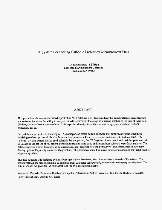
A System For Storing Cathodic Protection Measurement Data
T.J. Bowman and E.I. Husa Lockheed Martin Hanford Company
Richland,WA 99352
ABSTRACT
This paper describes a custom cathodic protection (CP) database, and discusses how this combination of data structure and software improves the ability to analyze cathodic protection. This may be a unique solution to the task of managing CP data, and may have value to others. This paper is primarily about the database design, and not about cathodic protection, per se.
Every database project is a balancing act, A developer can create custom software that performs complex operations requiring modest operator skills. On the other hand, custom software is expensive to both create and maintain. The Hanford CP data system will be used primarily by one person, the CP Engineer. It was concluded that this position could be trained to use off-the-shelf, general purpose database to store data, and spreadsheet software to perform analyses. The database product allows flexibility in data reporting, and enforces referential integrity. The spreadsheet allows many display options. Especially useful are the graphics, This solution entailed minimal computer coding and may lend itself to adoption by others.
The data strncture was designed by a database application developer, with close guidance from the CP engineer. The system will require modest amounts of attention from computer support staff, primarily for new query development. The data slrnctures are provided in this report, and are available electronically
Keywords: Cathodic Protection Database, Computer, Polarization, Native Potentials, Test Points, Rectifiers, Anodes, Loop, Tap Settings, Access, CP, Excel
INTRODUCTION
Lockheed Martin Hanford Company (LMHC) manages cathodic protection systems spreading across miles of the Hanford Site, on the dry side of Washington state. Thirty-six (36) rectifiers supply current into 48 anode loops, which in turn serve over 1500 buried anodes. Data are taken at the 36 rectifiers and 563 test stations on a regular basis. One of the responsibilities of the CP Engineer is following rectifier output trends (voltage and current). Another is determining which rectifiers may be contributing to high or low voltage readings at a given test point. Some anode loops have overlapping affects on one another, so the association is not always obvious. Data must be stored in such a way that these interrelationships can be studied effectively.
LMHC met these challenges by developing a unique solution to manage these data. This application stores a wide range of information about the cathodic protection system and its performance. System requirements have been set, the data structure created, and existing data entered.
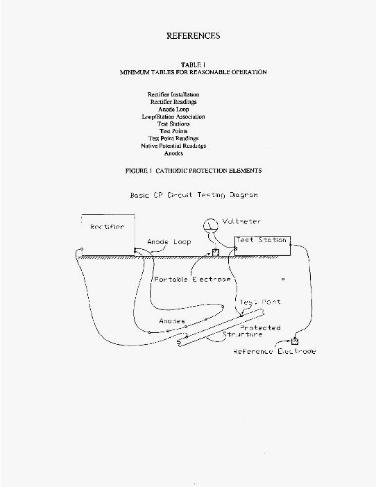
The Hanford cathodic protection system (see typical CP arrangement, Figure 1) is composed primarily of: rectifiers, anode loops, anodes, protected structures, test points, reference electrodes, and test stations. Baseline measurements of voltage and current were recorded and are referred to as “Acceptance Test Procedure” or ATP data. Rectifier performance measurements are made bimonthly and on an as-needed basis. Test points are surveyed annually and on an as-needed basis. These measurements are all stored in the database, where they can be used for creating reports and plots.
DISCUSSION
Process
Figure 2 describes the work processes that use the CP database. The circles are the processes, and the rectangles are participants in those processes. A single-headed arrow means that a participant was consumed (or transformed) in the process, a double-headed arrow means it was not. For example, a data sheet is transformed from the ‘unrecorded’ state, to the ‘recorded’ state by a process called ‘data entered’. This is performed by the CP Engineer, using the CP database. The bold arrows between processes show the flow of time (precedence).
A normalized data strncture based on a relational data model was used. Fields were included for future use, where data was not readily at hand. In the working database, many fields on these records are presently empty.
Referential Integrity
Referential Integrity describes a condition where relationships between records remain valid, and that you do not accidentally delete information in one table, that may be referenced by a record in another table. A general-purpose database product handles referential integrity, without developing computer code in-house.
Should someone wish to delete a rectitier from the Rectifier Installation table, two possible conditions exist. If there are no references to this rectifier in other tables, such as Drawings with Rectifiers, or Anode Loop, then the delete is performed directly. If not, then you are given the option of halting the deletion (as it was possibly an error), or having all other records with that rectifier which was referenced deleted as well (cascading deletes). Similarly, if one changed the ID or name of a rectifier in one table, then all related records are instantly updated with the new name as well.
Cardinality
Data tables that are linked by a common field (such as Test Station ID) may be related in one of three ways. Records in one table may be related on a one-to-one, or on a one-to-many, or on a many-to-many basis. This relationship is called ‘cardinality’. It refers to an enforced relationship between data tables. The most common relationship is the one-to-many type. It means that the linking field (called a key field) will be unique in one table (no duplicate values) and non-unique in the other. These relationships are shown in Figure 3. Each line between tables shows a relationship. A line with a ‘1’ at one end, and an I-’ symbol at the other shows that a one-to-many relationship was established by the system developer.

This is an important key to understanding how these tables are related. For example, there may be several anode loops (typically two) associated with a given rectifier. Each reclifier ID is associated with one and only one location (and other data). The database software enforces this relationship, so one doesn’t inadvertently re-enter data about an object that already exists.
An example describing the one-to-many relationship follows: the Anode Loop table has fields for a Loop ID, Rectifier ID and Comments. Before one can enter a value into the Anode Loop table, such as ‘EN-RECT-23’. for a Rectifier ID, it must first exist in the Rectifier Installation table (referential integrity). Furthermore, each table has a ‘key’ field (or combination of fields) which makes each record unique (a requirement for proper relational design). The Rectifier ID field was selected to be the key field for the Rectifier Installation table. This means there can be only one record in the Rectifier Installation table with ‘EN-RECT-23’ as the Rectifier ID value. The combination of Rectifier ID field and Loop ID field makes each record unique in the Anode Loop table. This means that one rectifier may have several loops associated with it (typically two, at our site). Because there can be more than one enUy in the Anode Loop table with the same Rectifier ID field, we say that there exists a one-to-many reletionship between the Anode Loop table and the Rectifier Data table.
Appendix A lists the Anode Loop table and Anodes table data structures (as examples).
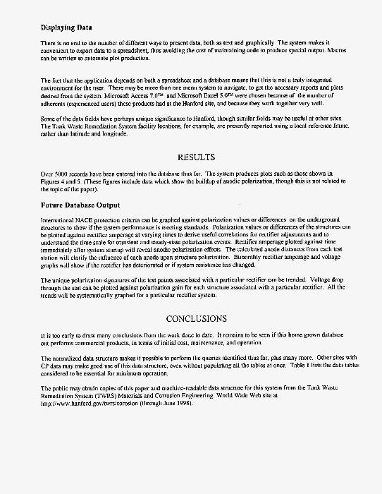
Displaying Data
There is no end to the number of different ways to present data, both as text and graphically. The system makes it convenient to export data to a spreadsheet, thus avoiding the cost of maintaining code to produce special output. Macros can be written to automate plot production.
The fact that the application depends on both a spreadsheet and a database means that this is not a truly integrated environment for the user. There may be more than one menu system to navigate, to get the necessary reports and plots desired from the system. Microsof? Access 7.0m and Microsof? Excel 5.OW were chosen because of the number of adherents (experienced users) these products had at the Hanford site, and because they work together very well.
Some of the data fields have perhaps unique significance to Hanford, though similar fields may be useful at other sites. The Tank Waste Remediation System facility locations, for example, are presently reported using a local reference frame, rather than latitude and longitude.
RESULTS
Over 5000 records have been entered into the database thus far. The system produces plots such as those shown in Figures 4 and 5 . (These figures include data which show the buildup of anodic polarization, though this is not related to the topic of the paper).
Future Database Output
International NACE protection criteria can be graphed against polarization values or differences on the underground structures to show if the system performance is meeting standards. Polarization values or differences of the structures can be plotted against rectifier amperage at varying times to derive useful correlations for rectifier adjustments and to understand the time scale for transient and steady-state polarization events. Rectifier amperage plotted against time immediately afler system startup will reveal anodic polarization effects. The calculated anode distances from each test station will clarify the influence of each anode upon structure polarization. Bimonthly rectifier amperage and voltage graphs will show if the rectifier has deteriorated or if system resistance has changed.
The unique polarization signatures of the test points associated with a particular rectifier can be trended. Voltage drop through the soil can be plotted against polarization gain for each structure associated with a particular rectifier. All the trends will be systematically graphed for a particular rectifier system.
CONCLUSIONS
It is too early to draw many conclusions from the work done to date. It remains to be seen if this home grown database out performs commercial products, in terms of initial cost, maintenance, and operation.
The normalized data structnre makes it possible to perform the queries identified thus far, plus many more. Other sites with CP data may make good use of this data structure, even without populating all the tables at once. Table 1 lists the data tables considered to be essential for minimum operation.
The public may obtain copies of this paper and machine-readable data structure for this system from the Tank Waste Remediation System (TWRS) Materials and Corrosion Engineering World Wide Web site at htrp~llwww.hanford.govltwrdcorosion (through June 1998).
REFERENCES
TABLE I MINIMUM TABLES FOR REASONABLE OPERATION
Rectifier Installation Rectifier Readings
Anode Loop LoopIStation Association
Test Stations Test Points
Test Point Readings Native Potential Readings
Anodes
FIGURE 1 CATHODIC PROTECTION ELEMENTS
Basic CP Ci rcu i t Tes t ing Diagram
R e c t i f i e r k. ~
Anode Loop T e s t S t a t i o n
\
Re fe rence E l e c t r o d e

FIGURE 2 PROCESS DESCRIPTION MODEL
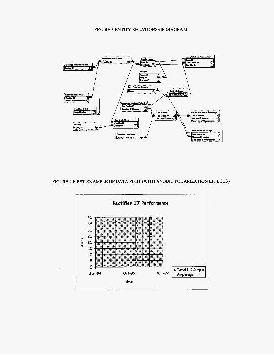
FIGURE 3 ENTITY RELATIONSHIP DIAGRAM
FIGURE 4 FIRST EXAMPLE OF DATA PLOT (WITH ANODIC POLARIZATION EFFECTS)
Rectifier 17 Performance
Jun-94 Oct-95 Mar97
time
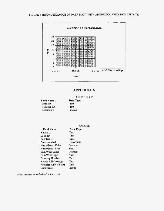
FIGURE 5 SECOND EXAMPLE OF DATA PLOT (WITH ANODIC POLARIZATION EFFECTS)
35
30
25
P 20 a > 15
10
5
0
Ji
Rectifier 17 Performance
in-94 Oct-95 Mar -97 p G z Voltogcj
Field Name Lwp ID Rectifier ID Comments
Field Name Anode ID Loop ID Rectifier ID Date Installed NortWSouth Value NortWSouth Type EasWest Value EasWest Type Drawing Number Anode ATP Voltage Rectifier ATP Voltage Comments
Final version to include all fables. eih
APPENDIX A
ANODE LOOP Data Type text text memo
ANODES Data Type Text Text Text DatwTime Number Text Number Text Text Text Text memo


![cathodic protection in practise · 2 [CATHODIC PROTECTION/BM] CATHODIC PROTECTION P E FRANCIS 1 INTRODUCTION The first practical use of cathodic protection is generally credited to](https://img.pdfslide.us/doc/110x75/5ace93c87f8b9ae2138b87e4/cathodic-protection-in-cathodic-protectionbm-cathodic-protection-p-e-francis.jpg)