Embed Size (px)
Citation preview
1546 IEEE COMMUNICATIONS SURVEYS & TUTORIALS, VOL. 15, NO. 4, FOURTH QUARTER 2013
A Survey and Tutorial on Low-Complexity TurboCoding Techniques and a Holistic Hybrid ARQ
Design ExampleHong Chen, Robert G. Maunder, Member, IEEE and Lajos Hanzo, Fellow, IEEE
Abstract—Hybrid Automatic Repeat reQuest (HARQ) hasbecome an essential error control technique in communicationnetworks, which relies on a combination of arbitrary errorcorrection codes and retransmissions. When combining turbocodes with HARQ, the associated complexity becomes a criticalissue, since conventionally iterative decoding is immediatelyactivated after each transmission, even though the iterativedecoder might fail in delivering an error-free codeword evenafter a high number of iterations. In this scenario, preciousbattery-power would be wasted. In order to reduce the associatedcomplexity, we will present design examples based on MultipleComponents Turbo Codes (MCTCs) and demonstrate that theyare capable of achieving an excellent performance based on thelowest possible memory octally represented generator polynomial(2, 3)o. In addition to using low-complexity generator polynomi-als, we detail two further techniques conceived for reducing thecomplexity. Firstly, an Early Stopping (ES) strategy is invokedfor curtailing iterative decoding, when its Mutual Information(MI) improvements become less than a given threshold. Secondly,a novel Deferred Iteration (DI) strategy is advocated for thesake of delaying iterative decoding, until the receiver confidentlyestimates that it has received sufficient information for successfuldecoding. Our simulation results demonstrate that the MCTCaided HARQ schemes are capable of significantly reducing thecomplexity of the appropriately selected benchmarkers, which isachieved without degrading the Packet Loss Ratio (PLR) andthroughput.
Index Terms—Multiple-component turbo codes, ARQ, auto-matic repeat request, EXIT chart, iterative detection.
I. TURBO CODING COMPLEXITY AND MOTIVATION
IN TELECOMMUNICATION networks, reliable transmis-sion constitutes one of the ultimate design objectives.
Forward Error Correction (FEC) [1] and Automatic RepeatreQuest (ARQ) [2] are the most salient solutions, which arecapable of enhancing the achievable transmission reliability.
The family of FEC codes is capable of recovering the infor-mation bits by incorporating carefully controlled redundancy
Manuscript received April 23, 2012; revised November 5, 2012. Thefinancial support of the EPSRC, UK, of the RCUK under the auspicesof the India-UK Advanced Technology Center (IU-ATC), that of the EU’sCONCERTO project and the European Research Council’s Advanced FellowGrant is gratefully acknowledged. H. Chen would also like to acknowledgethe support of the Fundamental Research Funds for the Central Universities,China under Grants No. ZYGX2011J058.
H. Chen is with the School of Computer Science and Engineering, Univer-sity of Electronic Science and Technology of China, Chengdu 610054, China(e-mail: [email protected]). She is also with the CCSR, University ofSurrey, GU2 7XH, U.K.
R. G. Maunder and L. Hanzo are with School of Electronics and ComputerScience, University of Southampton, UK (e-mail: [email protected]).
Digital Object Identifier 10.1109/SURV.2013.013013.00079
based on different codes. The first FEC code was the singleerror correcting Hamming code [3], which was invented in1950. Since then, more potent codes have been developed,such as Bose-Chaudhuri-Hocquenghem (BCH) block codes,Convolutional Codes (CC) and turbo codes as well as fountaincodes. Figure 1.1 of [1] outlines the brief history of FECcodes. The ratio of the number of information bits to the totalnumber of information and parity bits defines the normalizedthroughput or the coding rate. Shannon’s channel capacitydetermines the upper bound of the coding rate that any FECcode may be able to achieve at a certain Signal Noise Ratio(SNR). Since the transmission of these parity bits requiresan increased bandwidth, the maximum coding rate that anFEC code can have, while still recovering the information bitsbecomes a useful criterion for quantifying the capability ofFEC codes. Their decoding complexity is also a critical factorin the evaluation of FEC codes. Researchers have studied theassociated tradeoff between these two aspects, when choosinga specific FEC code for a communication system.
A. Turbo Code Complexity
As one of the most powerful codes in the FEC family,turbo codes [4] have shown capacity-achieving capability bycombining two parallel concatenated Recursive SystematicConvolutional (RSC) codes at the transmitter. At the receiver,iterative exchange of soft information is carried out betweenthe two so-called Bahl, Cocke, Jelinek and Raviv (BCJR)decoders [5]. The BCJR decoder is also often referred to as theMaximum A posteriori (MAP) algorithm, which estimates adecoded bit by selecting the specific transition path havingthe maximum a posteriori probability among all transitionpaths from one state to the next in the decoder’s trellis [6].Since the calculation of each transition probability involvesthe exploration of all possible paths through the trellis, thecomplexity of the BCJR decoder is potentially high, especiallywhen several iterations are used for exchanging soft informa-tion between two BCJR decoders.
Researchers have been striving for reducing the complexityof turbo codes, approaching the problem from all aspects. Firstof all, they aimed for simplifying the MAP algorithm itself.As a result, the Max-Log-MAP algorithm proposed in 1995[7] significantly decreased The MAP algorithm’s complexity,whilst imposing only a modest performance degradation. Thiswas achieved by transforming the multiplications involved inthe MAP algorithm to low-complexity additions carried out
1553-877X/13/$31.00 c© 2013 IEEE
CHEN et al.: A SURVEY AND TUTORIAL ON LOW-COMPLEXITY TURBO CODING TECHNIQUES AND A HOLISTIC HYBRID ARQ DESIGN EXAMPLE 1547
in the logarithmic domain, and then further approximatingthe calculation of its basic function of ln (
∑i e
xi) by asingle term, namely by the maximum one. In order to avoidthe modest, but not negligible performance degradation ofthe Max-Log-MAP decoder, Robertson et al. [7] suggestedemployment of the Jacobean logarithm for correcting theapproximation, which may be expressed as [7]:
ln (ex1 + ex2) = max(x1, x2) + f(·), (1)
where the function f(·) represents a correction term, whichmay be pre-stored in a look-up table storing the valuesof ln
(1 + e−|x1−x2|
). This technique is referred to as the
Log-MAP algorithm, which is invoked in most of today’sturbo decoding implementations. Naturally, the Max-Log-MAP algorithm has a reduced complexity, which is achievedat the cost of suffering a slight performance degradation. Bycontrast, the Log-MAP algorithm imposes a somewhat highercomplexity. In 2004, Park [8] combined these two algorithmsfor the sake of achieving a near-MAP performance at the costof a reduced complexity.
Even though the per-iteration complexity has been reducedby the above-mentioned innovative solutions, the complexityof turbo codes remains substantial due to their iterative nature.It has been observed that the first few iterations tend to resultin the most substantial performance improvements. However,after these high-gain initial iterations, the improvements typi-cally become marginal. Hence, it has been suggested in [9] tocurtail iterations, when the Mutual Information (MI) improve-ments between the soft-information and its hard-decision ver-sion become low. The Early Stopping (ES) decoding strategiesproposed by numerous researchers [10]–[28] may be classifiedinto the following categories:
1) Setting the number of iterationsConventional turbo codes tend to employ a fixed number
of iterations, albeit this is somewhat wasteful. In [10], Kimet al. set the number of iterations according to the estimatedChannel State Information (CSI), which reflects the currentchannel SNR. The appropriate number of iterations was thenpre-determined for different CSIs in [10] based on the extrinsicinformation improvements experienced in consecutive itera-tions of the BCJR decoders. Furthermore, the authors of [11]exploited the cross correlation between the Log-LikelihoodRatios (LLRs) for finding the specific SNR threshold, at whichthe Extrinsic Information Transfer (EXIT) chart has a ‘just’open tunnel. For the SNRs below this threshold, the numberof iterations is set to zero, otherwise it is set to a fixed number.
2) Early stopping based on MI thresholdingIn turbo codes, the mutual information increase achieved by
each iteration may be represented by diverse variables. Sincethe amount of MI improvement eventually converges to zero,the MI improvement may be used as a stopping criterion,because if M(i) is below the threshols of T (i), indicatingmarginal iteration gains, then the iterations may be curtailed.More specifically, this implies that the iterative decodingoperations will be curtailed, when an appropriately chosenfunction of the MI M(i) becomes less than the threshold T (i)at the ith iteration. The threshold T (i) can be determinedby observing the MI results of offline simulations. The ESstrategies of [12], [13] quantified M(i) in terms of the Cross
Entropy (CE) between the distributions of the a posterioriLLRs generated by the two BCJR decoders, namely
M(i) =∑k
|�L(i)e2 (uk)|2
exp(|L(i)1 (uk)|)
, (2)
where Le2 denotes the extrinsic LLRs generated by the secondBCJR decoder, L1 represents the a posteriori LLRs of thefirst BCJR decoder, while uk is the kth estimated informationbit. When the CE becomes less than the threshold of T (i) =10−3 ·M(1), the iterations are stalled. By contrast, the authorsof [14] used the average entropy for representing M(i). Theaverage entropy per bit for a packet having a length of N maybe calculated as
M(i) = − 1
N
N∑k=1
[p(uk = 0|r) log p(uk = 0|r)+
p(uk = 1|r) log p(uk = 1|r)], (3)
where p(uk = 0|r) represents the a posteriori probability ofthe estimated bit uk = 0 based on the received symbol r.Bearing in mind that the a posteriori LLR output of the BCJRdecoder represents the logarithmic form of the a posterioriprobability, Equation 3 may also be expressed in terms of the aposteriori LLRs. Furthermore, Chen et al. [14] also suggestedspecific threshold values for different SNR ranges.
The following contributions further developed the ES phi-losophy based on the polarity changes of the LLRs [15], [16]during iterative decoding, since the hard decision output onlydepends on the polarity of the LLRs. The techniques proposedin [15] observed the relative frequency of polarity changes atthe ith iteration and introduced the Sign Change Ratio (SCR)as another stopping criterion. The MI improvement M(i) wasestimated by the number of polarity changes in Le2 betweentwo consecutive iterations over the packet length N and thecorresponding thresholds T (i) set for the SCR in [15] were0.005 to 0.03. Furthermore, the authors of [16] extended theSCR stopping criterion to the Sign Difference Ratio (SDR),which calculates the ratio of the sign differences between the apriori and the extrinsic LLRs. In [17], [18], the absolute valueof the LLR was invoked as a metric used for ES. Explicitly,the minimum absolute value of the LLRs was suggested forcharacterizing the M(i) in [17], while the mean of the absoluteLLR values was advocated in [18].
3) Hard Decision Aided ESHard Decision Aided (HDA) ES was proposed in [15],
where hard decisions were invoked at each iteration for thea posteriori LLRs L
(i−1)2 (u) and L
(i)2 (u) was acquired from
the second BCJR decoder. If the estimated bits of bothHDA decoding operations agreed with each other, iterativedecoding was concluded. The HAD may save more iterationsat low to medium SNRs, but may increase the complexityat high SNRs. Therefore, Taffin [19] derived a generalizedHDA algorithm, which calculates the ratio of the number ofdifferent HDA bits between two consecutive iterations over theentire packet length N . Furthermore, different thresholds werederived for high SNRs and low/medium SNRs. An ImprovedHDA (IHDA) was then proposed in [20], which achieved asimilar performance to the original HDA of [15] without theextra storage requirement of HDA, since it simply compared
1548 IEEE COMMUNICATIONS SURVEYS & TUTORIALS, VOL. 15, NO. 4, FOURTH QUARTER 2013
the agreement between the hard decision versions of the apriori LLRs and of the a posteriori LLRs gleaned from thesecond BCJR decoder at the ith iteration.
4) Cyclic Redundancy Check CheckCyclic Redundancy Check (CRC) aided Turbo-CRC de-
coding has become a widely used method of controlling theactivation/deactivation of iterative decoding [21]–[23], whichcombines turbo codes with CRC codes for the sake of detect-ing, whether there are any residual errors after turbo decoding.According to this method, each turbo encoded packet will bepassed to a CRC encoder for appending a number of checkbits. At the receiver, the classic CRC check will be applied tothe estimated bits, which are hard-decided on the basis of the aposteriori LLRs gleaned from the second BCJR decoder [21]or in fact from both BCJR decoders [22]. If the CRC checkindicates a decoding success, the iterative decoding will beceased. This CRC aided ES technique is capable of indicatingperfect decoding. However, it fails to reduce the number ofdecoding iterations for transmissions over hostile channels.
5) The input-output consistency check.The decoding process conceived for the a posteriori LLRs
of the parity bits is similar to that of the original informationbits, although it is not necessary for the BCJR decoder tooutput them at the end of the decoding process. Based on thisfact, the authors of [24], [25] proposed an ES strategy referredto as the input-output consistency check, where the BCJRdecoder outputs the a posteriori LLRs of both the informationbits as well as of the parity bits. After each iteration, theestimated information bits and parity bits may be obtainedby subjecting these a posteriori LLRs to hard decision. Theestimated information bits will be encoded by the sameconvolutional encoder as that employed at the transmitter.Then, the resultant output parity bits will be compared tothe parity bits estimated from the a posteriori LLRs. If theyare identical, the iterative decoding stops; otherwise, it willcontinue until the maximum number of iterations has beenexhausted.
6) Bit-based ESRecently, it was found in [26] that the convergence speed
of each bit during the iterative decoding is different. Moreexplicitly, it was demonstrated that a substantial fraction of aposteriori LLRs of the information bits become stable after afew iterations. Hence, we refer to them as the ’converged’bits. The remaining modest number of ’un-converged’ bitsrequire more decoding iterations for achieving a reliableestimation. Using this property, the bit-based ES strategiesproposed in [26]–[28] curtail the iterative decoding for the‘converged bits’, when a certain MI threshold has been reachedby them. More explicitly, the iterative decoding will onlycontinue for the specific bits having a low reliability, whichmay be quantified in terms of their LLR magnitudes [26].The decoding complexity imposed is therefore reduced byprocessing a reduced number of bits in the second stage. Inorder to improve the achievable decoding performance, theauthors of [27], [28] grouped the non-converged bits alongwith their adjacent converged bits into a set and invoked partialiterative decoding for these small sets. The benefit of thistechnique is that the high-reliability converged bits assist inimproving the reliability of the non-converged bits.
B. Motivation and Organization
Based on the Log-MAP algorithm and on the above-mentioned ES strategies, turbo codes have found applicationsin diverse scenarios. Their application may also be combinedwith other techniques, such as for example, Hybrid ARQ(HARQ) techniques, or with Decode and Forward (DF) re-laying. In these applications, the complexity may becomehigh, since the iterative decoding process may be activatedmultiple times. Specifically, turbo coded HARQ, which willbe detailed in Section III, performs turbo decoding after eachreception of the (re)transmitted packets. Likewise, a turbocoded relay-aided network may activate turbo decoding bothat the relay and at the destination. The packets received bothfrom the source and from the relay also have to be combinedwith the aid of soft extrinsic information exchange, which isreminiscent of turbo decoding at the destination. However,the iterative detection complexity imposed may be furtherincreased, when invoking multiple relays.
From a theoretical perspective, both HARQ and relay-aidednetworks rely on the incremental redundancy extracted fromthe retransmissions or from the relays. However, the ES strate-gies reviewed in this paper never considered this additionalinformation increment. Yet, it is plausible that initially it maybe unnecessary to activate any iterations during the HARQprocess, since the decoding convergence may be substantiallyaccelerated by the forthcoming incremental information, henceresulting in a reduced number of iterations. Furthermore, thepreviously proposed complexity reduction methods never con-sidered the influence of the specific component convolutionalcodes, especially the memory length m of their forward andfeedback Generator Polynomials (GPs), which determines thenumber of states in the trellis. As mentioned above, theMAP algorithm will estimate a specific bit by evaluatingall the probabilities of all possible state transitions for thatparticular bit in the trellis. Since the number of trellis statesincreases exponentially with the memory length of the GPs,the complexity is dramatically reduced, if m is a small value,whist maintaining an unimpaired performance.
In this paper, we set out to reduce the complexity of turbocoded applications by explicitly considering both the incre-mental information gleaned, as well as the influence of thecomponent codes’ memory length. HARQ will be consideredas our design example for discussing the complexity reductionachieved with the aid of information combination. Neverthe-less, the proposed methods are general, hence they are alsoapplicable to turbo coded relay networks. More explicitly, ournovel contributions may be formulated as follows,
• Multiple Component Turbo Codes (MCTCs) are de-signed, which have the shortest possible memory lengthGPs of (2, 3)o, where the underscore o indicates the octalrepresentation.
• Based on these MCTCs, we conceived an ES strategy,which curtails iterations, when ever the MI incrementbecomes less than a specific threshold, which may bedetermined by an offline training process.
• A so-called Deferred Iteration (DI) method was proposedfor delaying the commencement of iterations, until suffi-cient information is deemed to be received.
CHEN et al.: A SURVEY AND TUTORIAL ON LOW-COMPLEXITY TURBO CODING TECHNIQUES AND A HOLISTIC HYBRID ARQ DESIGN EXAMPLE 1549
The paper is organized as follows. In Section II, both HARQarrangements and the techniques of information combinationare reviewed. The existing turbo coded HARQ schemes arediscussed in Section III, where an equation is conceived forcalculating the complexity of turbo coded HARQ. Further-more, in Section IV, we demonstrate that MCTCs exhibitan attractive performance even when the GPs having thelowest possible memory of m = 1 represented by (2, 3)oare adopted. Therefore, MCTCs may be beneficially invokedfor constructing low-complexity turbo-coded HARQ schemes.Furthermore, in Section V two methods are proposed for find-ing an optimal number of iterations for a specific normalizedtarget throughput and Packet Loss Ratio (PLR) performance.More specifically, the ES strategy to be detailed in Section V-Acurtails the iterative decoding process after each transmissionattempt, when the MI improvement of additional iterationsbecomes low. By contrast, in Section V-B, we introducethe DI method, which delays the commencement of iterativedecoding, until the total MI is deemed to be sufficiently highfor guaranteeing successful decoding with a high probability.
II. HARQ INTRODUCTION
When the receiver detects that a packet has been correctlyreceived, it will feed back a positive ACKnowledgement(ACK) message to the transmitter. Otherwise, it may send backa negative ACK or wait for the transmitter to time out. Thetransmitter will continue retransmitting the specific informa-tion packet, until it receives the ACK message or a maximumretry limit is reached. In the early ARQ designs, each re-transmitted packet was independently processed. Therefore,a packet may become discarded, regardless of how manyretransmissions are allowed, if all transmissions encounterhostile channel conditions. However, in more sophisticatedschemes, all corrupted replicas may be combined with the aidof soft decisions in order to successfully decode the originalinformation bits. This is philosophically similar to the actionof repetition codes [29]. In other words, this forms a naiveexample of the combination of FEC and ARQ, which isreferred to as HARQ.
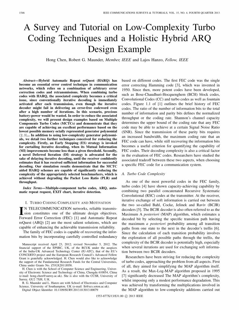
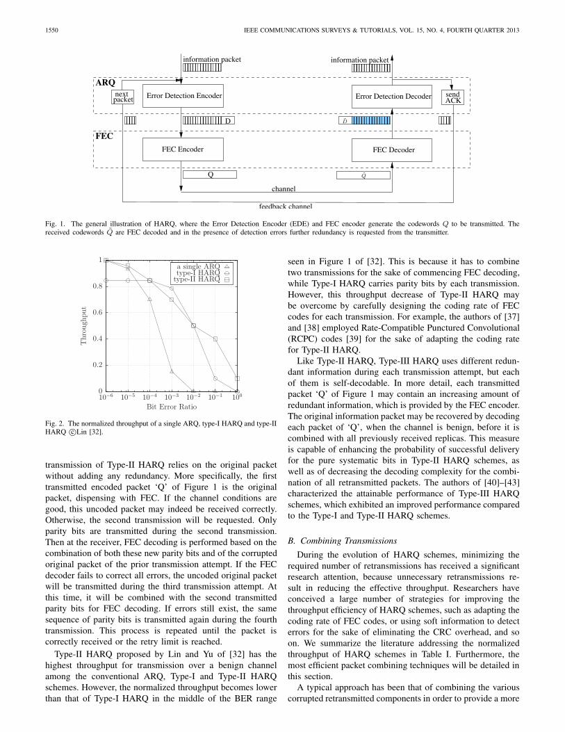
HARQ schemes overcome the disadvantages of FEC andARQ. More specifically, FEC may waste bandwidth by un-necessarily transmitting parity bits for protecting the trans-missions over a channel having a good condition, while ARQdegrades the throughput drastically for transmissions over ahostile channel. In general, HARQ schemes combine ARQwith FEC techniques, as illustrated in Figure 1. It may beobserved that each information packet will be accompaniedby a number of check bits of an error detection code, forexample a CRC scheme. These check bits are denoted by ‘D’in Figure 1. Then, the resultant packet is passed to the FECencoder. The encoded packet represented by ‘Q’ in Figure 1may have different forms depending on the specific type ofthe HARQ scheme. For example, it may be the input packetaccompanied by a number of error correction parity bits. Inthis case, the packet length is increased. Alternatively, thepacket may only contain parity bits, while having either thesame or a potentially reduced length in comparison to theoriginal packet, if it was prepared for retransmissions, whichmay hence be referred to as incremental redundancy.
At the receiver, the FEC decoder performs decoding basedon all the received bits, where different HARQ schemes havedifferent packet combining strategies during this decodingoperation. The decoding may only process the currently re-ceived packet Q, as seen in Figure 1. However, combining theprevious corrupted replicas with the current one for the sake ofdecoding them together becomes a better method. If decodingerrors still persist in the estimated message, the current replicais discarded, triggering a retransmission by sending a NegativeACKnowledgement (NACK) or by simply waiting for thetransmitter to time out. This process is repeated, until a retrylimit is reached or the packet is correctly received.
Based on the development of FEC techniques, HARQschemes have been classified into Type-I, Type-II and Type-IIIcategories, which overcame the shortcomings of the previousversions. Furthermore, the achievable throughput also benefitsfrom combining the retransmitted packets, which evolved fromusing the naive technique of no combining at all in the earlydays, to combining parts of the retransmitted packets andfinally to combining all received replicas.
A. Three Types of HARQAs discussed before, HARQ schemes combine the ad-
vantages of ARQ and FEC arrangements for the sake ofachieving a high throughput. However, for the earliest conceptof HARQ proposed and analyzed in 1970 [30], the authorsof [31] claimed that separate ARQ or FEC may attain abetter performance than HARQ when considering differentSNR regions. The straightforward combination of ARQ andFEC is referred to as Type-I HARQ. More explicitly, theFEC-encoded packet ‘Q’ seen in Figure 1 is the originalpacket, which is complemented by a number of parity bits.This packet will be (re)transmitted for all (re)transmissions.At the receiver, all corrupted packets will be thrown away.Each FEC decoding action is performed solely for a singleencoded packet.
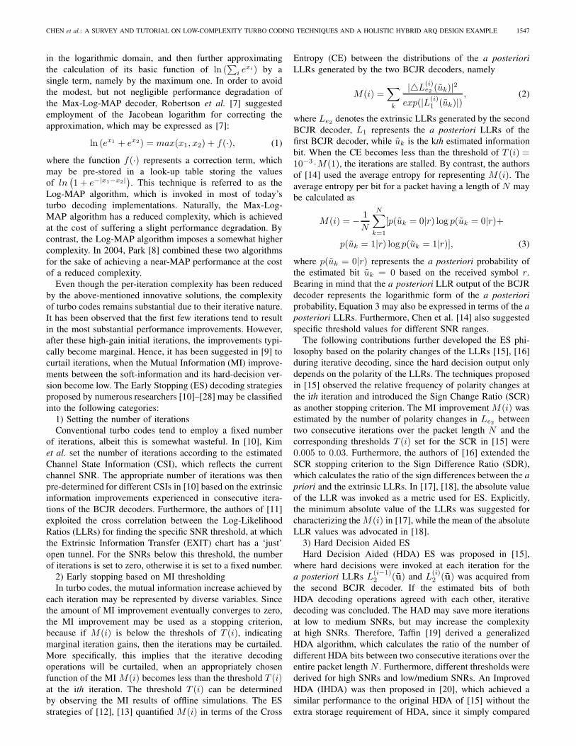
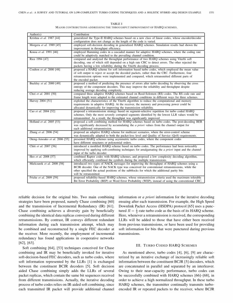
Figure 1 of [32] was reproduced here for completeness asFigure 2, which shows the achievable throughput of a singleretransmission attempt, which we refer to as conventionalARQ. This ARQ scheme is also compared to both Type-IHARQ as well as to Type-II HARQ in Figure 2. Observethat Type-I HARQ is capable of improving the attainablethroughput of conventional ARQ, apart from Bit Error Ratios(BER) below about 10−4. This is because the FEC scheme’scoding gain results in a reduced number of retransmissionsrequired for the successful delivery of a packet. However,if the channel conditions are sufficiently good, the resultantreduced number of errors may not require any FEC paritybits. In this situation, the resultant normalized throughputis reduced by the unnecessary parity bits. By contrast, ifthe channel conditions are hostile, the FEC code may notbe capable of correcting all errors for each transmission.Hence, the normalized throughput tends to zero, similar tothat of conventional ARQ. Most of the early HARQ schemesdesigned during the 1970s and early 1980s [30], [33]–[36]belong to the family of Type-I HARQs.
Type-II HARQ was proposed by Lin and Yu [32] in 1982.In order to eliminate the throughput degradation of Type-I HARQ for transmission over a benign channel, the first
1550 IEEE COMMUNICATIONS SURVEYS & TUTORIALS, VOL. 15, NO. 4, FOURTH QUARTER 2013
ARQsendACK
Error Detection Encoder Error Detection Decoder
D
����������������
����������������
����������������
������ ���������������� ������FEC
feedback channel
channel
packetnext
FEC Encoder
information packet
Q
FEC Decoder
information packet
D
Q
Fig. 1. The general illustration of HARQ, where the Error Detection Encoder (EDE) and FEC encoder generate the codewords Q to be transmitted. Thereceived codewords Q are FEC decoded and in the presence of detection errors further redundancy is requested from the transmitter.
type-II HARQtype-I HARQa single ARQ
Bit Error Ratio
Thro
ugh
put
10010−110−210−310−410−510−6
1
0.8
0.6
0.4
0.2
0
Fig. 2. The normalized throughput of a single ARQ, type-I HARQ and type-IIHARQ c©Lin [32].
transmission of Type-II HARQ relies on the original packetwithout adding any redundancy. More specifically, the firsttransmitted encoded packet ‘Q’ of Figure 1 is the originalpacket, dispensing with FEC. If the channel conditions aregood, this uncoded packet may indeed be received correctly.Otherwise, the second transmission will be requested. Onlyparity bits are transmitted during the second transmission.Then at the receiver, FEC decoding is performed based on thecombination of both these new parity bits and of the corruptedoriginal packet of the prior transmission attempt. If the FECdecoder fails to correct all errors, the uncoded original packetwill be transmitted during the third transmission attempt. Atthis time, it will be combined with the second transmittedparity bits for FEC decoding. If errors still exist, the samesequence of parity bits is transmitted again during the fourthtransmission. This process is repeated until the packet iscorrectly received or the retry limit is reached.
Type-II HARQ proposed by Lin and Yu of [32] has thehighest throughput for transmission over a benign channelamong the conventional ARQ, Type-I and Type-II HARQschemes. However, the normalized throughput becomes lowerthan that of Type-I HARQ in the middle of the BER range
seen in Figure 1 of [32]. This is because it has to combinetwo transmissions for the sake of commencing FEC decoding,while Type-I HARQ carries parity bits by each transmission.However, this throughput decrease of Type-II HARQ maybe overcome by carefully designing the coding rate of FECcodes for each transmission. For example, the authors of [37]and [38] employed Rate-Compatible Punctured Convolutional(RCPC) codes [39] for the sake of adapting the coding ratefor Type-II HARQ.
Like Type-II HARQ, Type-III HARQ uses different redun-dant information during each transmission attempt, but eachof them is self-decodable. In more detail, each transmittedpacket ‘Q’ of Figure 1 may contain an increasing amount ofredundant information, which is provided by the FEC encoder.The original information packet may be recovered by decodingeach packet of ‘Q’, when the channel is benign, before it iscombined with all previously received replicas. This measureis capable of enhancing the probability of successful deliveryfor the pure systematic bits in Type-II HARQ schemes, aswell as of decreasing the decoding complexity for the combi-nation of all retransmitted packets. The authors of [40]–[43]characterized the attainable performance of Type-III HARQschemes, which exhibited an improved performance comparedto the Type-I and Type-II HARQ schemes.
B. Combining Transmissions
During the evolution of HARQ schemes, minimizing therequired number of retransmissions has received a significantresearch attention, because unnecessary retransmissions re-sult in reducing the effective throughput. Researchers haveconceived a large number of strategies for improving thethroughput efficiency of HARQ schemes, such as adapting thecoding rate of FEC codes, or using soft information to detecterrors for the sake of eliminating the CRC overhead, and soon. We summarize the literature addressing the normalizedthroughput of HARQ schemes in Table I. Furthermore, themost efficient packet combining techniques will be detailed inthis section.
A typical approach has been that of combining the variouscorrupted retransmitted components in order to provide a more
CHEN et al.: A SURVEY AND TUTORIAL ON LOW-COMPLEXITY TURBO CODING TECHNIQUES AND A HOLISTIC HYBRID ARQ DESIGN EXAMPLE 1551
TABLE IMAJOR CONTRIBUTIONS ADDRESSING THE THROUGHPUT IMPROVEMENT OF HARQ SCHEMES.
Author(s) ContributionKrishna et al. 1987 [44] generalized the Type-II HARQ schemes based on a new class of linear codes, whose encoder/decoder
configuration does not change as the length of the code is varied.Morgera et al. 1989 [45] employed soft-decision decoding in generalized HARQ schemes. Simulation results had shown the
improvement in throughput efficiency.Kousa et al. 1991 [46] employed Hamming codes in a cascaded manner for adaptive HARQ schemes, where the coding rate
could be adaptively matched to the prevailing channel condition.Rice 1994 [47] compared and analyzed the throughput performance of two HARQ schemes using Viterbi soft
decoding, one of which still depended on a high rate CRC to detect errors. The other rejected thepackets having a low reliability during the Viterbi decoding process.
Coulton et al. 2000 [48] proposed a HARQ scheme for soft information based turbo codes, which employed the mean valueof soft output to reject or accept the decoded packets, rather than the CRC. Furthermore, fourretransmission options were implemented and compared, which retransmitted different parts ofthe encoded packet.
Buckley et al. 2000 [49] proposed a method of predicting the presence of errors after turbo decoding by observing the crossentropy of the component decoders. This may improve the reliability and throughput despitereducing average decoding complexity.
Choi et al. 2001 [50] compared three adaptive HARQ schemes based on Reed-Solomon (RS) codes. The RS code rate andframe length were adapted to the estimated channel conditions in different ways for three schemes.
Harvey 2004 [51] exploited the characteristics of the Viterbi algorithm to reduce the computational and memoryrequirements in adaptive HARQ. At the receiver, the memory and processing power could beallocated dynamically for improving the transmission reliability.
Cao et al. 2004 [52] proposed a retransmission strategy based on segment-selective repetition for turbo coded HARQschemes. Only the most severely corrupted segments identified by the lowest LLR values would beretransmitted. As a result, the throughput was significantly improved.
Holland et al. 2005 [53] proposed a soft combining method for HARQ schemes based on turbo codes. The post-decoding BERwas significantly decreased by accumulating the a priori values from the channel output foreach additional retransmission.
Zhang et al. 2006 [54] proposed an adaptive HARQ scheme for multicast scenarios, where the error-control schemewas dynamically adapted to both the packet-loss level and Quality of Service (QoS) requirements.
Oteng-Amoako et al. 2006 [55] presented HARQ schemes using asymmetric turbo codes, where the component codeshave different structures or polynomial orders.
Chiti et al. 2007 [56] introduced a modified HARQ scheme based on turbo codes. The performance had been noticeablyimproved by applying soft-combining techniques for amalgamating the a priori input and the channelinput of the turbo decoder.
Heo et al. 2008 [57] combined Raptor codes with HARQ schemes, and proposed a low complexity decoding algorithm,which efficiently combined the symbols during the multiple transmissions.
Mielczarek et al. 2008 [58] introduced two types of NACK messages for improving the throughput of HARQ schemes using aBCJR decoder. One of the NACK type was conceived for conventional retransmissions, while theother specified the actual positions of the subblocks for which the additional parity bitswill be retransmitted.
Fricke et al. 2009 [59] proposed reliability-based HARQ schemes, whose retransmission criteria used the maximum tolerableBit Error Probability (BEP) or Word Error Probability (WEP), instead of using the conventional CRC.
reliable decision for the original bits. Two main combiningstrategies have been proposed, namely Chase combining [60]and the transmission of Incremental Redundancy (IR) [61].Chase combining achieves a diversity gain by beneficiallycombining the identical data replicas conveyed during differentretransmissions. By contrast, IR conveys different redundantinformation during each transmission attempt, which maybe combined and reconstructed by a single FEC decoder atthe receiver. More recently, the employment of incrementalredundancy has found applications in cooperative networks[62], [63].
Soft combining [64], [53] techniques conceived for Chasecombining and IR may be beneficially invoked for iterativesoft-decision-based FEC decoders, such as turbo codes, wheresoft information represented by the LLRs [1] is exchangedbetween the constituent BCJR decoders [5]. Soft decisionaided Chase combining simply adds the LLRs of severalpacket replicas, which contain the same bit sequences receivedfrom different transmissions. Actually, the iterative decodingprocess of turbo codes relies on IR-aided soft combining, sinceeach transmitted IR packet will provide additional channel
information or a priori information for the iterative decodingensuing after each transmission. For example, the High SpeedDownlink Packet Access (HSDPA) protocol [65] uses a punc-tured R = 1
3 -rate turbo code as the basis of its HARQ scheme.Here, whenever a retransmission is received, the correspondingLLRs will be added to those that have either been receivedfrom previous transmissions, or have been used for providingsoft information for bits that were punctured during previoustransmissions.
III. TURBO CODED HARQ SCHEMES
As mentioned above, turbo codes [4], [6], [9] are charac-terized by an iterative exchange of increasingly reliable softinformation between the constituent BCJR [5] decoders, whichare concatenated in parallel and separated by an interleaver.Owing to their near-capacity performance, turbo codes canbe successfully combined with HARQ schemes [66]–[68], inorder to achieve a high normalized throughput. In these turboHARQ schemes, the transmitter continually transmits turbo-encoded IR or repeated packets to the receiver, where BCJR
1552 IEEE COMMUNICATIONS SURVEYS & TUTORIALS, VOL. 15, NO. 4, FOURTH QUARTER 2013
j
1
URC
URC
2
1
for j>1
punc
punc
b(j)
π
π
a1
a2
a(j)1
b1
b2
a
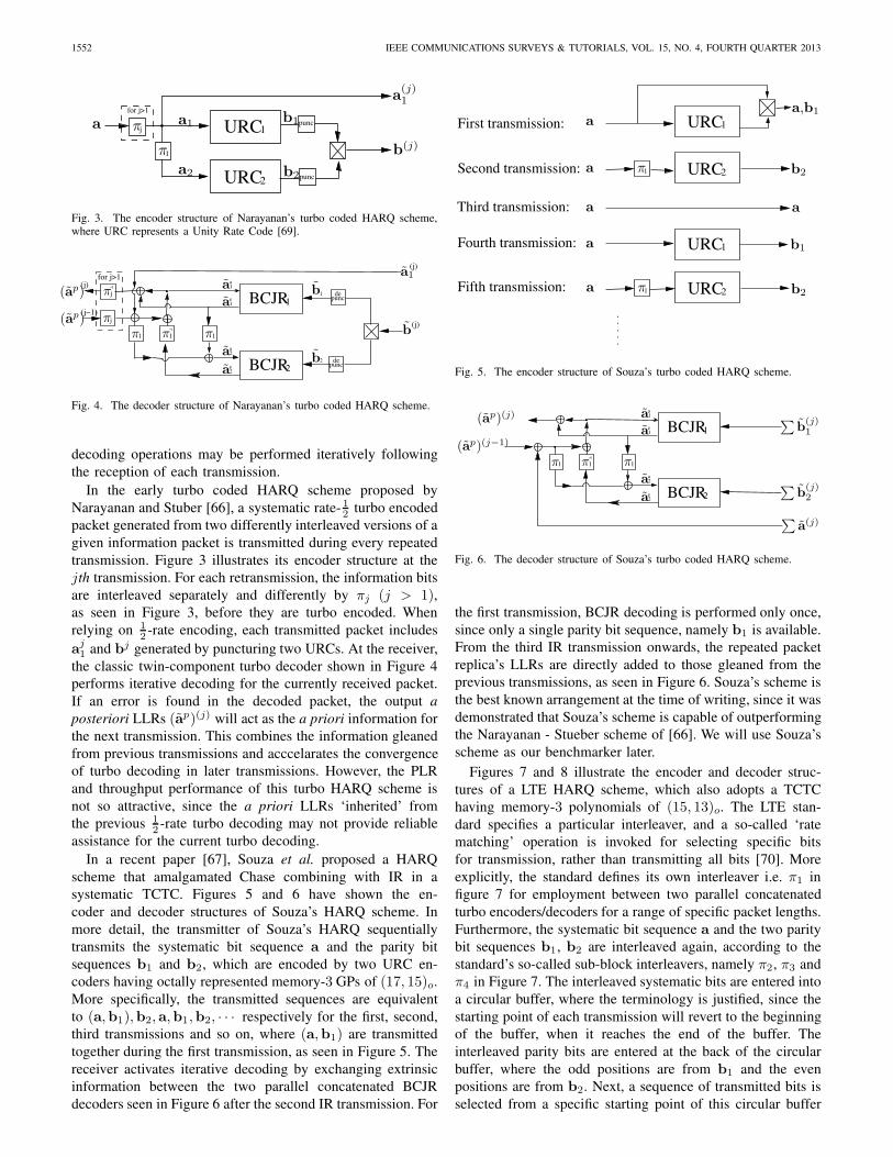
Fig. 3. The encoder structure of Narayanan’s turbo coded HARQ scheme,where URC represents a Unity Rate Code [69].
BCJR2
BCJR1
11
1
(j)
depunc
depunc
(j)
1
j(j)
(j−1)j
a
a2
e2
1
1e
1
1
2
for j>1
π ππ b
a1
π(ap)
(ap) π
a
a
a
b
ba
Fig. 4. The decoder structure of Narayanan’s turbo coded HARQ scheme.
decoding operations may be performed iteratively followingthe reception of each transmission.
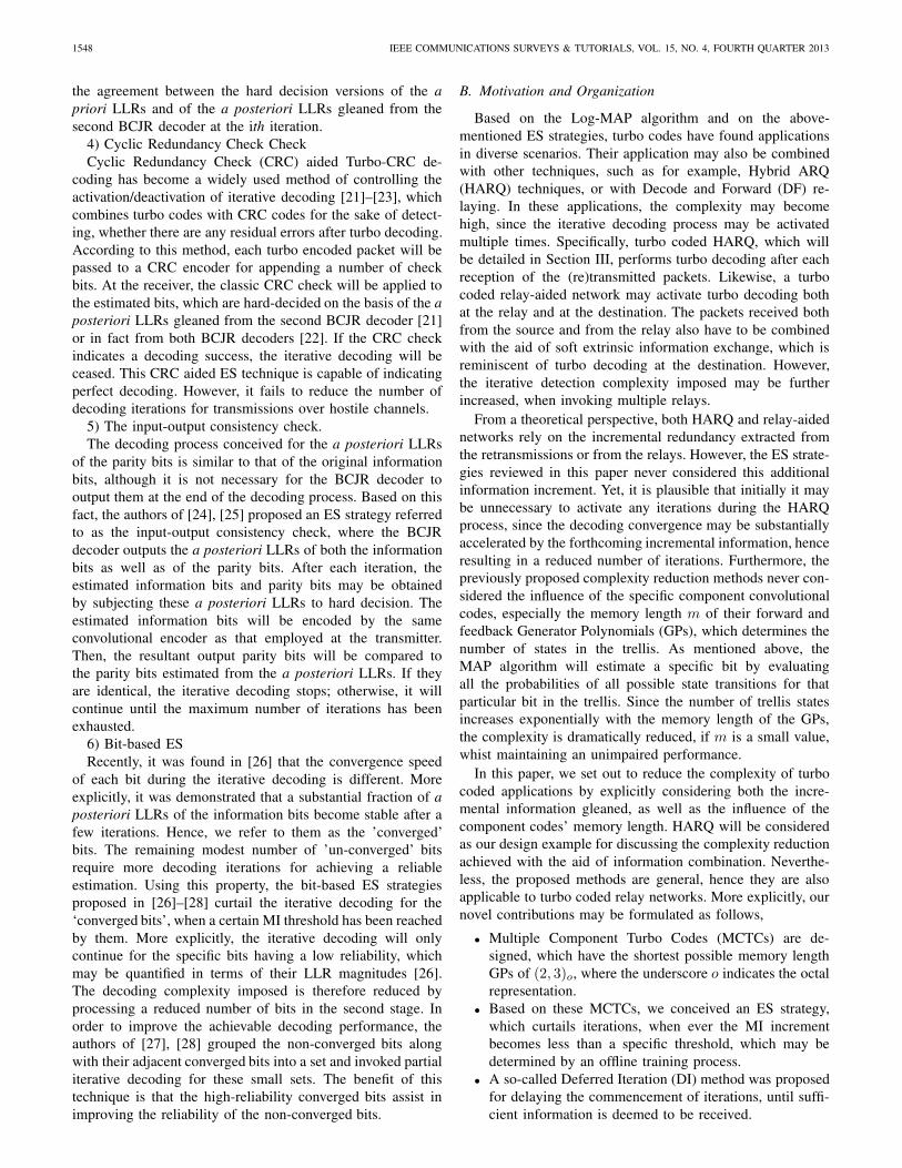
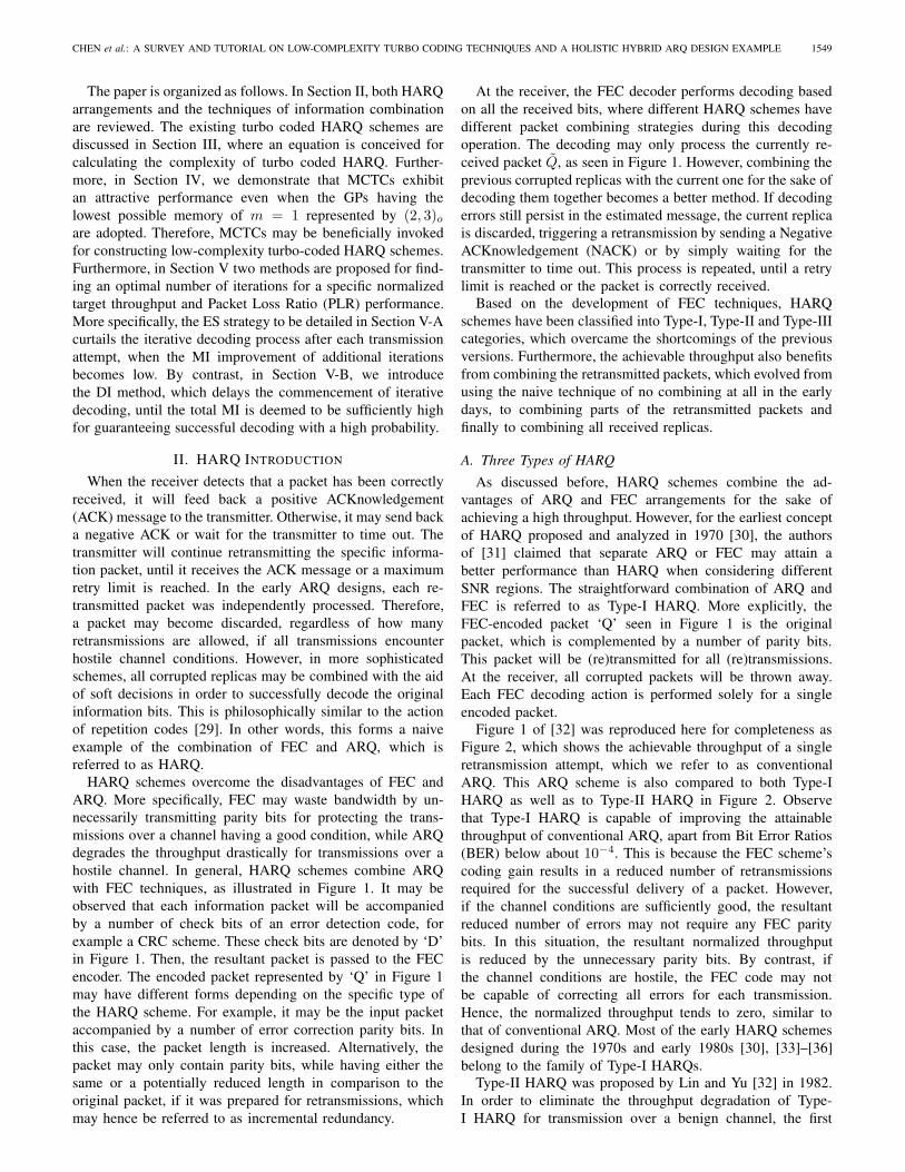
In the early turbo coded HARQ scheme proposed byNarayanan and Stuber [66], a systematic rate- 12 turbo encodedpacket generated from two differently interleaved versions of agiven information packet is transmitted during every repeatedtransmission. Figure 3 illustrates its encoder structure at thejth transmission. For each retransmission, the information bitsare interleaved separately and differently by πj (j > 1),as seen in Figure 3, before they are turbo encoded. Whenrelying on 1
2 -rate encoding, each transmitted packet includesaj1 and bj generated by puncturing two URCs. At the receiver,the classic twin-component turbo decoder shown in Figure 4performs iterative decoding for the currently received packet.If an error is found in the decoded packet, the output aposteriori LLRs (ap)(j) will act as the a priori information forthe next transmission. This combines the information gleanedfrom previous transmissions and acccelarates the convergenceof turbo decoding in later transmissions. However, the PLRand throughput performance of this turbo HARQ scheme isnot so attractive, since the a priori LLRs ‘inherited’ fromthe previous 1
2 -rate turbo decoding may not provide reliableassistance for the current turbo decoding.
In a recent paper [67], Souza et al. proposed a HARQscheme that amalgamated Chase combining with IR in asystematic TCTC. Figures 5 and 6 have shown the en-coder and decoder structures of Souza’s HARQ scheme. Inmore detail, the transmitter of Souza’s HARQ sequentiallytransmits the systematic bit sequence a and the parity bitsequences b1 and b2, which are encoded by two URC en-coders having octally represented memory-3 GPs of (17, 15)o.More specifically, the transmitted sequences are equivalentto (a,b1),b2, a,b1,b2, · · · respectively for the first, second,third transmissions and so on, where (a,b1) are transmittedtogether during the first transmission, as seen in Figure 5. Thereceiver activates iterative decoding by exchanging extrinsicinformation between the two parallel concatenated BCJRdecoders seen in Figure 6 after the second IR transmission. For
1
1
URC1
URC2
URC2Second transmission:
First transmission:
Fifth transmission:
Fourth transmission: URC1
Third transmission:
π
π
a
a
a
a
a b2
a
b1
b2
b1a,
Fig. 5. The encoder structure of Souza’s turbo coded HARQ scheme.
BCJR2
BCJR1
11
a
a2
e2
1
1e
11 π ππ
aa
aa
(ap)(j−1)
(ap)(j) ∑b(j)
1
∑b(j)
2
∑a(j)
Fig. 6. The decoder structure of Souza’s turbo coded HARQ scheme.
the first transmission, BCJR decoding is performed only once,since only a single parity bit sequence, namely b1 is available.From the third IR transmission onwards, the repeated packetreplica’s LLRs are directly added to those gleaned from theprevious transmissions, as seen in Figure 6. Souza’s scheme isthe best known arrangement at the time of writing, since it wasdemonstrated that Souza’s scheme is capable of outperformingthe Narayanan - Stueber scheme of [66]. We will use Souza’sscheme as our benchmarker later.
Figures 7 and 8 illustrate the encoder and decoder struc-tures of a LTE HARQ scheme, which also adopts a TCTChaving memory-3 polynomials of (15, 13)o. The LTE stan-dard specifies a particular interleaver, and a so-called ‘ratematching’ operation is invoked for selecting specific bitsfor transmission, rather than transmitting all bits [70]. Moreexplicitly, the standard defines its own interleaver i.e. π1 infigure 7 for employment between two parallel concatenatedturbo encoders/decoders for a range of specific packet lengths.Furthermore, the systematic bit sequence a and the two paritybit sequences b1, b2 are interleaved again, according to thestandard’s so-called sub-block interleavers, namely π2, π3 andπ4 in Figure 7. The interleaved systematic bits are entered intoa circular buffer, where the terminology is justified, since thestarting point of each transmission will revert to the beginningof the buffer, when it reaches the end of the buffer. Theinterleaved parity bits are entered at the back of the circularbuffer, where the odd positions are from b1 and the evenpositions are from b2. Next, a sequence of transmitted bits isselected from a specific starting point of this circular buffer
CHEN et al.: A SURVEY AND TUTORIAL ON LOW-COMPLEXITY TURBO CODING TECHNIQUES AND A HOLISTIC HYBRID ARQ DESIGN EXAMPLE 1553
1
2
URC
URC
2
1 3
4
buffercircular
π
π
a1
a2
π
π
a a
b1
b2
c(j)
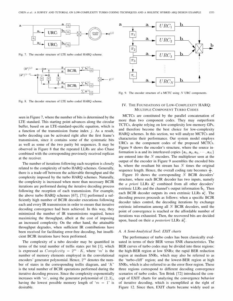
Fig. 7. The encoder structure of LTE turbo coded HARQ scheme.
BCJR2
BCJR1
11
a
a2
e2
1
1e
11
1
2
1
3
1
4
π ππ
a
aa
(ap)(j−1)
(ap)(j)
π
π
π
a ∑b(j)
1
∑b(j)
2
∑a(j)
c(j)
Fig. 8. The decoder structure of LTE turbo coded HARQ scheme.
seen in Figure 7, where the number of bits is determined by theLTE standard. This starting point advances along the circularbuffer, based on an LTE-standard-specific equation, which isa function of the transmission frame index j. As a result,turbo decoding can be activated right after the first frame’stransmission, since it contains some of the systematic bitsas well as some of the two parity bit sequences. It may beobserved in Figure 8 that the repeated LLRs are also Chasecombined with the corresponding previously received replicasat the receiver.
The number of iterations following each reception is closelyrelated to the complexity of turbo HARQ schemes. Generally,there is a trade-off between the achievable throughput and thecomplexity imposed by the turbo HARQ schemes. Naturally,the complexity is increased when more than necessary BCJRiterations are performed during the iterative decoding processfollowing the reception of each transmission. For example,the above turbo HARQ schemes [67], [71] performed a suf-ficiently high number of BCJR decoder executions followingeach and every IR transmission in order to ensure that iterativedecoding convergence had been achieved. In this way, theyminimized the number of IR transmissions required, hencemaximizing the throughput, albeit at the cost of imposingan increased complexity. On the other hand, the attainablethroughput degrades, when sufficient IR contributions havebeen received for facilitating error-free decoding, but insuffi-cient BCJR iterations have been performed.
The complexity of a tubo decoder may be quantified interms of the total number of trellis states per bit [1], whichis expressed as Complexity = 2m · K , where ‘m’ is thenumber of memory elements employed in the convolutionalencoders’ generator polynomial. Hence, 2m denotes the num-ber of states in the corresponding trellis diagram, and ‘K’is the total number of BCJR operations performed during theiterative decoding process. Since the complexity exponentiallyincreases with ‘m’, using the generator polynomial of (2, 3)ohaving the lowest possible memory length of ‘m = 1’ isdesirable.
1
N−1
N
1
2
33
2
N
a
a
aπ1
π2
π3
aπ
b
b
b
bURC3
URC1
URC2
b
a
URCN
Fig. 9. The encoder structure of a MCTC using N URC components.
IV. THE FOUNDATIONS OF LOW-COMPLEXITY HARQ:MULTIPLE COMPONENT TURBO CODES
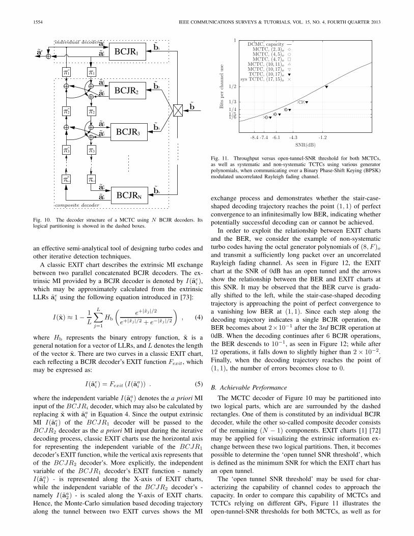
MCTCs are constituted by the parallel concatenation ofmore than two component codes. They may outperformTCTCs, despite relying on low-complexity low-memory GPs,and therefore become the best choice for low-complexityHARQ schemes. In this section, we will analyze MCTCs andcharacterize their performance. Our system model employsURCs as the component codes of the proposed MCTCs.Figure 9 shows the encoder’s structure, where the source in-formation is a and its interleaved copies {a1, a2, a3, · · · , aN}are entered into the N encoders. The multiplexer seen at theoutput of the encoder in Figure 9 assembles the encoded bitsb, where the resultant bit stream has N times the originalsequence length. Hence, the overall coding rate becomes 1
N .Figure 10 shows the corresponding N BCJR decoders’
structure, where each BCJR decoder has two inputs, namelythe a priori LLRs aai combined from all other decoders’extrinsic LLRs and the channel’s output information bi. Theneach BCJR decoder outputs its own extrinsic LLRs aei . Thedecoding process proceeds as follows: when a specific BCJRdecoder takes control, the decoding iterations by exchangeextrinsic information among all N BCJR decoders, until thepoint of convergence is reached or the affordable number ofiterations was exhausted. Then, the recovered bits are decidedupon, based on their a posteriori LLRs ap1.
A. A Semi-Analytical Tool: EXIT charts
The performance of turbo codes has been classically eval-uated in terms of their BER versus SNR characteristics. TheBER curves of turbo codes may be divided into three regions:the high-BER region at low SNRs; the rapid BER reductionregion at medium SNRs, which may also be referred to asthe ‘turbo-cliff’ region; and the lowest-BER region at highSNRs, which is also referred to as the error floor region. Thesethree regions correspond to different decoding convergencescenarios of turbo codes. Ten Brink [72] introduced the con-cept of EXIT charts for analyzing the convergence behaviorof iterative decoding, which is exemplified at the right ofFigure 12. Since then, EXIT charts became widely used as
1554 IEEE COMMUNICATIONS SURVEYS & TUTORIALS, VOL. 15, NO. 4, FOURTH QUARTER 2013
BCJR2
3BCJR
11
BCJRN
N−1 N−1
1
BCJR1ep
1
2
1
33
2
a
1
a2
e2
a
e3
N
e
3
a
N
11
2
3
N
1
π
π π
π
π
ππ
π
b
b
b
baa
b
a
aa
aa
aa
individual decoder
composite decoder
Fig. 10. The decoder structure of a MCTC using N BCJR decoders. Itslogical partitioning is showed in the dashed boxes.
an effective semi-analytical tool of designing turbo codes andother iterative detection techniques.
A classic EXIT chart describes the extrinsic MI exchangebetween two parallel concatenated BCJR decoders. The ex-trinsic MI provided by a BCJR decoder is denoted by I(aei ),which may be approximately calculated from the extrinsicLLRs aei using the following equation introduced in [73]:
I(x) ≈ 1− 1
L
L∑j=1
Hb
(e+|xj|/2
e+|xj|/2 + e−|xj|/2
), (4)
where Hb represents the binary entropy function, x is ageneral notation for a vector of LLRs, and L denotes the lengthof the vector x. There are two curves in a classic EXIT chart,each reflecting a BCJR decoder’s EXIT function Fexit, whichmay be expressed as:
I(aei ) = Fexit (I(aai )) . (5)
where the independent variable I(aai ) denotes the a priori MIinput of the BCJRi decoder, which may also be calculated byreplacing x with aai in Equation 4. Since the output extrinsicMI I(ae1) of the BCJR1 decoder will be passed to theBCJR2 decoder as the a priori MI input during the iterativedecoding process, classic EXIT charts use the horizontal axisfor representing the independent variable of the BCJR1
decoder’s EXIT function, while the vertical axis represents thatof the BCJR2 decoder’s. More explicitly, the independentvariable of the BCJR1 decoder’s EXIT function - namelyI(aa1) - is represented along the X-axis of EXIT charts,while the independent variable of the BCJR2 decoder’s -namely I(aa2) - is scaled along the Y-axis of EXIT charts.Hence, the Monte-Carlo simulation based decoding trajectoryalong the tunnel between two EXIT curves shows the MI
sys TCTC, (17, 15)oTCTC, (10, 17)oMCTC, (10, 17)oMCTC, (10, 11)oMCTC, (4, 7)oMCTC, (4, 5)oMCTC, (2, 3)o
DCMC, capacity
SNR(dB)
Bitsper
channel
use
-1.2-4.3-6.1-7.4-8.4
1
1/2
1/3
1/41/51/6
Fig. 11. Throughput versus open-tunnel-SNR threshold for both MCTCs,as well as systematic and non-systematic TCTCs using various generatorpolynomials, when communicating over a Binary Phase-Shift Keying (BPSK)modulated uncorrelated Rayleigh fading channel.
exchange process and demonstrates whether the stair-case-shaped decoding trajectory reaches the point (1, 1) of perfectconvergence to an infinitesimally low BER, indicating whetherpotentially successful decoding can or cannot be achieved.
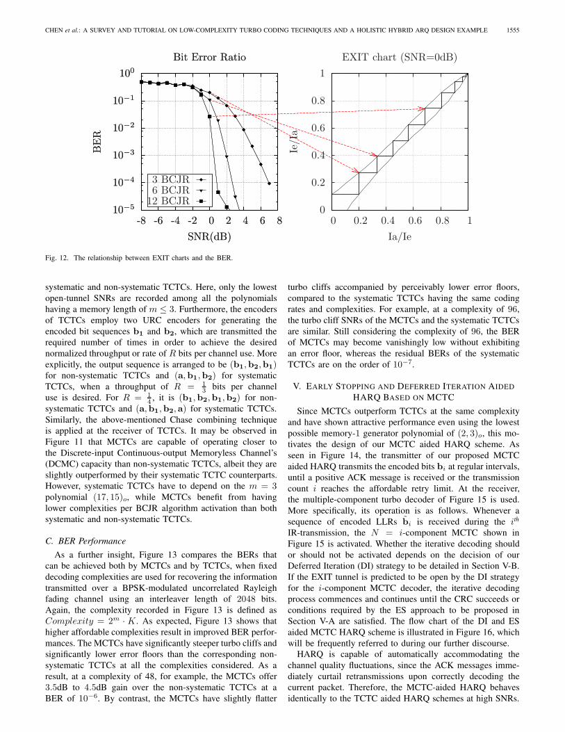
In order to exploit the relationship between EXIT chartsand the BER, we consider the example of non-systematicturbo codes having the octal generator polynomials of (8, F )oand transmit a sufficiently long packet over an uncorrelatedRayleigh fading channel. As seen in Figure 12, the EXITchart at the SNR of 0dB has an open tunnel and the arrowsshow the relationship between the BER and EXIT charts atthis SNR. It may be observed that the BER curve is gradu-ally shifted to the left, while the stair-case-shaped decodingtrajectory is approaching the point of perfect convergence toa vanishing low BER at (1, 1). Since each step along thedecoding trajectory indicates a single BCJR operation, theBER becomes about 2×10⁻¹ after the 3rd BCJR operation at0dB. When the decoding continues after 6 BCJR operations,the BER descends to 10−1, as seen in Figure 12; while after12 operations, it falls down to slightly higher than 2× 10⁻².Finally, when the decoding trajectory reaches the point of(1, 1), the number of errors becomes close to 0.
B. Achievable Performance
The MCTC decoder of Figure 10 may be partitioned intotwo logical parts, which are are surrounded by the dashedrectangles. One of them is constituted by an individual BCJRdecoder, while the other so-called composite decoder consistsof the remaining (N − 1) components. EXIT charts [1] [72]may be applied for visualizing the extrinsic information ex-change between these two logical partitions. Then, it becomespossible to determine the ‘open tunnel SNR threshold’, whichis defined as the minimum SNR for which the EXIT chart hasan open tunnel.
The ‘open tunnel SNR threshold’ may be used for char-acterizing the capability of channel codes to approach thecapacity. In order to compare this capability of MCTCs andTCTCs relying on different GPs, Figure 11 illustrates theopen-tunnel-SNR thresholds for both MCTCs, as well as for
CHEN et al.: A SURVEY AND TUTORIAL ON LOW-COMPLEXITY TURBO CODING TECHNIQUES AND A HOLISTIC HYBRID ARQ DESIGN EXAMPLE 1555
EXIT chart (SNR=0dB)
Ia/Ie
Ie/Ia
10.80.60.40.20
1
0.8
0.6
0.4
0.2
012 BCJR6 BCJR3 BCJR
Bit Error Ratio
SNR(dB)
BER
86420-2-4-6-8
100
10−1
10−2
10−3
10−4
10−5
Bit Error Ratio
SNR(dB)
BER
86420-2-4-6-8
100
10−1
10−2
10−3
10−4
10−5
Fig. 12. The relationship between EXIT charts and the BER.
systematic and non-systematic TCTCs. Here, only the lowestopen-tunnel SNRs are recorded among all the polynomialshaving a memory length of m ≤ 3. Furthermore, the encodersof TCTCs employ two URC encoders for generating theencoded bit sequences b1 and b2, which are transmitted therequired number of times in order to achieve the desirednormalized throughput or rate of R bits per channel use. Moreexplicitly, the output sequence is arranged to be (b1,b2,b1)for non-systematic TCTCs and (a,b1,b2) for systematicTCTCs, when a throughput of R = 1
3 bits per channeluse is desired. For R = 1
4 , it is (b1,b2,b1,b2) for non-systematic TCTCs and (a,b1,b2, a) for systematic TCTCs.Similarly, the above-mentioned Chase combining techniqueis applied at the receiver of TCTCs. It may be observed inFigure 11 that MCTCs are capable of operating closer tothe Discrete-input Continuous-output Memoryless Channel’s(DCMC) capacity than non-systematic TCTCs, albeit they areslightly outperformed by their systematic TCTC counterparts.However, systematic TCTCs have to depend on the m = 3polynomial (17, 15)o, while MCTCs benefit from havinglower complexities per BCJR algorithm activation than bothsystematic and non-systematic TCTCs.
C. BER Performance
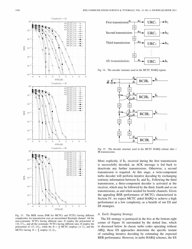
As a further insight, Figure 13 compares the BERs thatcan be achieved both by MCTCs and by TCTCs, when fixeddecoding complexities are used for recovering the informationtransmitted over a BPSK-modulated uncorrelated Rayleighfading channel using an interleaver length of 2048 bits.Again, the complexity recorded in Figure 13 is defined asComplexity = 2m · K . As expected, Figure 13 shows thathigher affordable complexities result in improved BER perfor-mances. The MCTCs have significantly steeper turbo cliffs andsignificantly lower error floors than the corresponding non-systematic TCTCs at all the complexities considered. As aresult, at a complexity of 48, for example, the MCTCs offer3.5dB to 4.5dB gain over the non-systematic TCTCs at aBER of 10−6. By contrast, the MCTCs have slightly flatter
turbo cliffs accompanied by perceivably lower error floors,compared to the systematic TCTCs having the same codingrates and complexities. For example, at a complexity of 96,the turbo cliff SNRs of the MCTCs and the systematic TCTCsare similar. Still considering the complexity of 96, the BERof MCTCs may become vanishingly low without exhibitingan error floor, whereas the residual BERs of the systematicTCTCs are on the order of 10−7.
V. EARLY STOPPING AND DEFERRED ITERATION AIDEDHARQ BASED ON MCTC
Since MCTCs outperform TCTCs at the same complexityand have shown attractive performance even using the lowestpossible memory-1 generator polynomial of (2, 3)o, this mo-tivates the design of our MCTC aided HARQ scheme. Asseen in Figure 14, the transmitter of our proposed MCTCaided HARQ transmits the encoded bits bi at regular intervals,until a positive ACK message is received or the transmissioncount i reaches the affordable retry limit. At the receiver,the multiple-component turbo decoder of Figure 15 is used.More specifically, its operation is as follows. Whenever asequence of encoded LLRs bi is received during the ith
IR-transmission, the N = i-component MCTC shown inFigure 15 is activated. Whether the iterative decoding shouldor should not be activated depends on the decision of ourDeferred Iteration (DI) strategy to be detailed in Section V-B.If the EXIT tunnel is predicted to be open by the DI strategyfor the i-component MCTC decoder, the iterative decodingprocess commences and continues until the CRC succeeds orconditions required by the ES approach to be proposed inSection V-A are satisfied. The flow chart of the DI and ESaided MCTC HARQ scheme is illustrated in Figure 16, whichwill be frequently referred to during our further discourse.
HARQ is capable of automatically accommodating thechannel quality fluctuations, since the ACK messages imme-diately curtail retransmissions upon correctly decoding thecurrent packet. Therefore, the MCTC-aided HARQ behavesidentically to the TCTC aided HARQ schemes at high SNRs.
1556 IEEE COMMUNICATIONS SURVEYS & TUTORIALS, VOL. 15, NO. 4, FOURTH QUARTER 2013
MCTC,1/6MCTC,1/5MCTC,1/4MCTC,1/3TCTC,1/6TCTC,1/5TCTC,1/4TCTC,1/3
sysTCTC,1/6sysTCTC,1/5sysTCTC,1/4sysTCTC,1/3
Complexity = 24
SNR(dB)
BER
86420-2-4-6-8
100
10−1
10−2
10−3
10−4
10−5
10−6
MCTC,1/6MCTC,1/5MCTC,1/4MCTC,1/3TCTC,1/6TCTC,1/5TCTC,1/4TCTC,1/3
sysTCTC,1/6sysTCTC,1/5sysTCTC,1/4sysTCTC,1/3
Complexity = 48
SNR(dB)
BER
86420-2-4-6-8
100
10−1
10−2
10−3
10−4
10−5
10−6
MCTC,1/6MCTC,1/5MCTC,1/4MCTC,1/3TCTC,1/6TCTC,1/5TCTC,1/4TCTC,1/3
sysTCTC,1/6sysTCTC,1/5sysTCTC,1/4sysTCTC,1/3
Complexity = 96
SNR(dB)
BER
86420-2-4-6-8
100
10−1
10−2
10−3
10−4
10−5
10−6
Fig. 13. The BER versus SNR for MCTCs and TCTCs having differentcomplexities for transmission over an uncorrelated Rayleigh channel. All thenon-systematic TCTCs having different rates R employ the polynomial of(10, 17)o , and all the systematic TCTCs having different rates R employ thepolynomial of (17, 15)o , while the R = 1
3MCTC employs (4, 7)o and the
MCTCs having R < 13
employ (2, 3)o .
i
1
First transmission:
Second transmission:
Third transmission:
i−1
URC
URC
URC
URC
2
1
i
3
2
i
π
π
ba
π
ith transmission:
a a1
a3 b3
b2
b1
a2
Fig. 14. The encoder structure used in the MCTC HARQ regime.
BCJR2
3BCJR
11
BCJR1
1
2
1
33
2
a
a2
e2
a
e3
i
e
3
a
i
11
2
3
i
1
p
i
1e
1
i−1 i−1
BCJR
π
π π
π
π
π πa ba
a
aa
aa
a
b
b
b
π
a
Fig. 15. The decoder structure used in the MCTC HARQ scheme after iIR-transmissions.
More explicitly, if b1 received during the first transmissionis successfully decoded, an ACK message is fed back todeactivate any further transmissions. Otherwise, a secondtransmission is required. At this stage, a twin-componentturbo decoder will perform iterative decoding by exchangingextrinsic information between b1 and b2. Following the thirdtransmission, a three-component decoder is activated at thereceiver, which may be followed by the third, fourth and so ontransmissions, as and when needed for hostile channels. Giventhe appealing BER performance of MCTCs characterized inSection IV, we expect MCTC aided HARQ to achieve a highperformance at a low complexity, as a benefit of our ES andDI strategies.
A. Early Stopping Strategy
The ES strategy is portrayed in the box at the bottom rightcorner of Figure 16 surrounded by the dotted line, whichis discussed below. In classic turbo codes operating withoutARQ, these ES approaches determine the specific instantof curtailing iterative decoding by estimating the expectedBER performance. However, in turbo HARQ schemes, the ES
CHEN et al.: A SURVEY AND TUTORIAL ON LOW-COMPLEXITY TURBO CODING TECHNIQUES AND A HOLISTIC HYBRID ARQ DESIGN EXAMPLE 1557
choose least recentlyoperated BCJR decoder
BCJR operationperform corresponding
successfullyreceived
packet is
Start
no
the EXIT tunnelstate corresponding to
current i pieces of received
check
information,if it is closed?
CRC?
yes dump all extrinsic LLRs
?
alreadydumped once during
this transmission
no
passed
yes
no
yes
no
yes
yes
ES
DI
not passed
the sorting operation to obtain:
search the LUT to obtain:
packetis lost
≤ Tinc?
r >retryLimit?
calculate I(br)
Ith(r) =Tr[I(bπ(1), · · · , I(bπ(r−1))]
I(bπ(1)), · · · , I(bπ(r))
r = 1
I(bπ(r)) ≤ Ith(r) − Idiff?
r = r + 1
get the rth transmission
It(aei ) ≥ Tmax?
It(aei ) − It−1(a
ei )
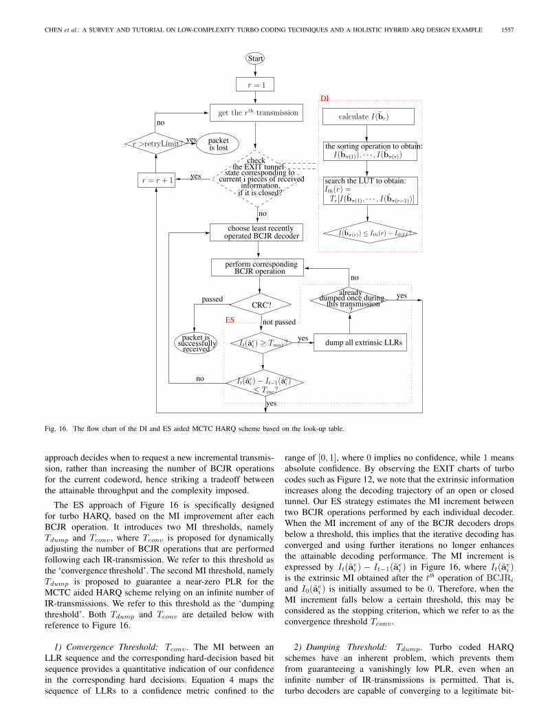
Fig. 16. The flow chart of the DI and ES aided MCTC HARQ scheme based on the look-up table.
approach decides when to request a new incremental transmis-sion, rather than increasing the number of BCJR operationsfor the current codeword, hence striking a tradeoff betweenthe attainable throughput and the complexity imposed.
The ES approach of Figure 16 is specifically designedfor turbo HARQ, based on the MI improvement after eachBCJR operation. It introduces two MI thresholds, namelyTdump and Tconv, where Tconv is proposed for dynamicallyadjusting the number of BCJR operations that are performedfollowing each IR-transmission. We refer to this threshold asthe ‘convergence threshold’. The second MI threshold, namelyTdump is proposed to guarantee a near-zero PLR for theMCTC aided HARQ scheme relying on an infinite number ofIR-transmissions. We refer to this threshold as the ‘dumpingthreshold’. Both Tdump and Tconv are detailed below withreference to Figure 16.
1) Convergence Threshold: Tconv. The MI between anLLR sequence and the corresponding hard-decision based bitsequence provides a quantitative indication of our confidencein the corresponding hard decisions. Equation 4 maps thesequence of LLRs to a confidence metric confined to the
range of [0, 1], where 0 implies no confidence, while 1 meansabsolute confidence. By observing the EXIT charts of turbocodes such as Figure 12, we note that the extrinsic informationincreases along the decoding trajectory of an open or closedtunnel. Our ES strategy estimates the MI increment betweentwo BCJR operations performed by each individual decoder.When the MI increment of any of the BCJR decoders dropsbelow a threshold, this implies that the iterative decoding hasconverged and using further iterations no longer enhancesthe attainable decoding performance. The MI increment isexpressed by It(a
ei ) − It−1(a
ei ) in Figure 16, where It(a
ei )
is the extrinsic MI obtained after the tth operation of BCJRi
and I0(aei ) is initially assumed to be 0. Therefore, when the
MI increment falls below a certain threshold, this may beconsidered as the stopping criterion, which we refer to as theconvergence threshold Tconv.
2) Dumping Threshold: Tdump. Turbo coded HARQschemes have an inherent problem, which prevents themfrom guaranteeing a vanishingly low PLR, even when aninfinite number of IR-transmissions is permitted. That is,turbo decoders are capable of converging to a legitimate bit-
1558 IEEE COMMUNICATIONS SURVEYS & TUTORIALS, VOL. 15, NO. 4, FOURTH QUARTER 2013
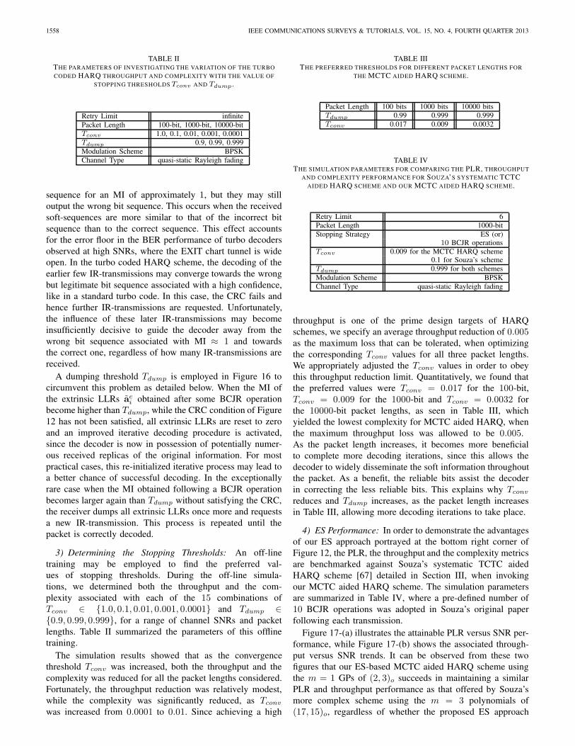
TABLE IITHE PARAMETERS OF INVESTIGATING THE VARIATION OF THE TURBOCODED HARQ THROUGHPUT AND COMPLEXITY WITH THE VALUE OF
STOPPING THRESHOLDS Tconv AND Tdump .
Retry Limit infinitePacket Length 100-bit, 1000-bit, 10000-bitTconv 1.0, 0.1, 0.01, 0.001, 0.0001Tdump 0.9, 0.99, 0.999Modulation Scheme BPSKChannel Type quasi-static Rayleigh fading
sequence for an MI of approximately 1, but they may stilloutput the wrong bit sequence. This occurs when the receivedsoft-sequences are more similar to that of the incorrect bitsequence than to the correct sequence. This effect accountsfor the error floor in the BER performance of turbo decodersobserved at high SNRs, where the EXIT chart tunnel is wideopen. In the turbo coded HARQ scheme, the decoding of theearlier few IR-transmissions may converge towards the wrongbut legitimate bit sequence associated with a high confidence,like in a standard turbo code. In this case, the CRC fails andhence further IR-transmissions are requested. Unfortunately,the influence of these later IR-transmissions may becomeinsufficiently decisive to guide the decoder away from thewrong bit sequence associated with MI ≈ 1 and towardsthe correct one, regardless of how many IR-transmissions arereceived.
A dumping threshold Tdump is employed in Figure 16 tocircumvent this problem as detailed below. When the MI ofthe extrinsic LLRs aei obtained after some BCJR operationbecome higher than Tdump, while the CRC condition of Figure12 has not been satisfied, all extrinsic LLRs are reset to zeroand an improved iterative decoding procedure is activated,since the decoder is now in possession of potentially numer-ous received replicas of the original information. For mostpractical cases, this re-initialized iterative process may lead toa better chance of successful decoding. In the exceptionallyrare case when the MI obtained following a BCJR operationbecomes larger again than Tdump without satisfying the CRC,the receiver dumps all extrinsic LLRs once more and requestsa new IR-transmission. This process is repeated until thepacket is correctly decoded.
3) Determining the Stopping Thresholds: An off-linetraining may be employed to find the preferred val-ues of stopping thresholds. During the off-line simula-tions, we determined both the throughput and the com-plexity associated with each of the 15 combinations ofTconv ∈ {1.0, 0.1, 0.01, 0.001, 0.0001} and Tdump ∈{0.9, 0.99, 0.999}, for a range of channel SNRs and packetlengths. Table II summarized the parameters of this offlinetraining.
The simulation results showed that as the convergencethreshold Tconv was increased, both the throughput and thecomplexity was reduced for all the packet lengths considered.Fortunately, the throughput reduction was relatively modest,while the complexity was significantly reduced, as Tconv
was increased from 0.0001 to 0.01. Since achieving a high
TABLE IIITHE PREFERRED THRESHOLDS FOR DIFFERENT PACKET LENGTHS FOR
THE MCTC AIDED HARQ SCHEME.
Packet Length 100 bits 1000 bits 10000 bitsTdump 0.99 0.999 0.999Tconv 0.017 0.009 0.0032
TABLE IVTHE SIMULATION PARAMETERS FOR COMPARING THE PLR, THROUGHPUT
AND COMPLEXITY PERFORMANCE FOR SOUZA’S SYSTEMATIC TCTCAIDED HARQ SCHEME AND OUR MCTC AIDED HARQ SCHEME.
Retry Limit 6Packet Length 1000-bitStopping Strategy ES (or)
10 BCJR operationsTconv 0.009 for the MCTC HARQ scheme
0.1 for Souza’s schemeTdump 0.999 for both schemesModulation Scheme BPSKChannel Type quasi-static Rayleigh fading
throughput is one of the prime design targets of HARQschemes, we specify an average throughput reduction of 0.005as the maximum loss that can be tolerated, when optimizingthe corresponding Tconv values for all three packet lengths.We appropriately adjusted the Tconv values in order to obeythis throughput reduction limit. Quantitatively, we found thatthe preferred values were Tconv = 0.017 for the 100-bit,Tconv = 0.009 for the 1000-bit and Tconv = 0.0032 forthe 10000-bit packet lengths, as seen in Table III, whichyielded the lowest complexity for MCTC aided HARQ, whenthe maximum throughput loss was allowed to be 0.005.As the packet length increases, it becomes more beneficialto complete more decoding iterations, since this allows thedecoder to widely disseminate the soft information throughoutthe packet. As a benefit, the reliable bits assist the decoderin correcting the less reliable bits. This explains why Tconv
reduces and Tdump increases, as the packet length increasesin Table III, allowing more decoding iterations to take place.
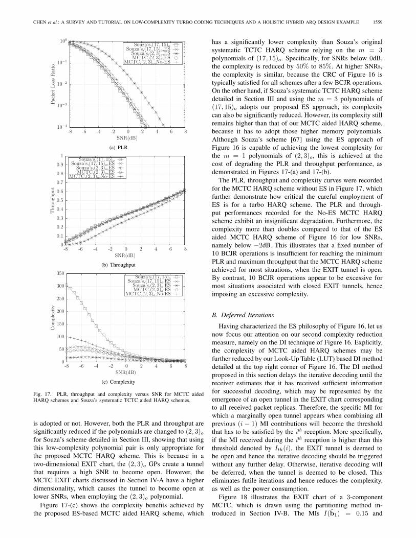
4) ES Performance: In order to demonstrate the advantagesof our ES approach portrayed at the bottom right corner ofFigure 12, the PLR, the throughput and the complexity metricsare benchmarked against Souza’s systematic TCTC aidedHARQ scheme [67] detailed in Section III, when invokingour MCTC aided HARQ scheme. The simulation parametersare summarized in Table IV, where a pre-defined number of10 BCJR operations was adopted in Souza’s original paperfollowing each transmission.
Figure 17-(a) illustrates the attainable PLR versus SNR per-formance, while Figure 17-(b) shows the associated through-put versus SNR trends. It can be observed from these twofigures that our ES-based MCTC aided HARQ scheme usingthe m = 1 GPs of (2, 3)o succeeds in maintaining a similarPLR and throughput performance as that offered by Souza’smore complex scheme using the m = 3 polynomials of(17, 15)o, regardless of whether the proposed ES approach
CHEN et al.: A SURVEY AND TUTORIAL ON LOW-COMPLEXITY TURBO CODING TECHNIQUES AND A HOLISTIC HYBRID ARQ DESIGN EXAMPLE 1559
MCTC,(2, 3)o,No-ESMCTC,(2, 3)o,ESSouza’s,(2, 3)o,ES
Souza’s,(17, 15)o,ESSouza’s,(17, 15)o
SNR(dB)
Pac
ket
Los
sR
atio
86420-2-4-6-8
100
10−1
10−2
10−3
10−4
(a) PLR
MCTC,(2, 3)o,No-ESMCTC,(2, 3)o,ESSouza’s,(2, 3)o,ES
Souza’s,(17, 15)o,ESSouza’s,(17, 15)o
SNR(dB)
Thro
ugh
put
86420-2-4-6-8
1
0.9
0.8
0.7
0.6
0.5
0.4
0.3
0.2
0.1
0
(b) Throughput
MCTC,(2, 3)o,No-ESMCTC,(2, 3)o,ESSouza’s,(2, 3)o,ES
Souza’s,(17, 15)o,ESSouza’s,(17, 15)o
SNR(dB)
Com
ple
xity
86420-2-4-6-8
350
300
250
200
150
100
50
0
(c) Complexity
Fig. 17. PLR, throughput and complexity versus SNR for MCTC aidedHARQ schemes and Souza’s systematic TCTC aided HARQ schemes.
is adopted or not. However, both the PLR and throughput aresignificantly reduced if the polynomials are changed to (2, 3)ofor Souza’s scheme detailed in Section III, showing that usingthis low-complexity polynomial pair is only appropriate forthe proposed MCTC HARQ scheme. This is because in atwo-dimensional EXIT chart, the (2, 3)o GPs create a tunnelthat requires a high SNR to become open. However, theMCTC EXIT charts discussed in Section IV-A have a higherdimensionality, which causes the tunnel to become open atlower SNRs, when employing the (2, 3)o polynomial.
Figure 17-(c) shows the complexity benefits achieved bythe proposed ES-based MCTC aided HARQ scheme, which
has a significantly lower complexity than Souza’s originalsystematic TCTC HARQ scheme relying on the m = 3polynomials of (17, 15)o. Specifically, for SNRs below 0dB,the complexity is reduced by 50% to 85%. At higher SNRs,the complexity is similar, because the CRC of Figure 16 istypically satisfied for all schemes after a few BCJR operations.On the other hand, if Souza’s systematic TCTC HARQ schemedetailed in Section III and using the m = 3 polynomials of(17, 15)o adopts our proposed ES approach, its complexitycan also be significantly reduced. However, its complexity stillremains higher than that of our MCTC aided HARQ scheme,because it has to adopt those higher memory polynomials.Although Souza’s scheme [67] using the ES approach ofFigure 16 is capable of achieving the lowest complexity forthe m = 1 polynomials of (2, 3)o, this is achieved at thecost of degrading the PLR and throughput performance, asdemonstrated in Figures 17-(a) and 17-(b).
The PLR, throughput and complexity curves were recordedfor the MCTC HARQ scheme without ES in Figure 17, whichfurther demonstrate how critical the careful employment ofES is for a turbo HARQ scheme. The PLR and through-put performances recorded for the No-ES MCTC HARQscheme exhibit an insignificant degradation. Furthermore, thecomplexity more than doubles compared to that of the ESaided MCTC HARQ scheme of Figure 16 for low SNRs,namely below −2dB. This illustrates that a fixed number of10 BCJR operations is insufficient for reaching the minimumPLR and maximum throughput that the MCTC HARQ schemeachieved for most situations, when the EXIT tunnel is open.By contrast, 10 BCJR operations appear to be excessive formost situations associated with closed EXIT tunnels, henceimposing an excessive complexity.
B. Deferred Iterations
Having characterized the ES philosophy of Figure 16, let usnow focus our attention on our second complexity reductionmeasure, namely on the DI technique of Figure 16. Explicitly,the complexity of MCTC aided HARQ schemes may befurther reduced by our Look-Up Table (LUT) based DI methoddetailed at the top right corner of Figure 16. The DI methodproposed in this section delays the iterative decoding until thereceiver estimates that it has received sufficient informationfor successful decoding, which may be represented by theemergence of an open tunnel in the EXIT chart correspondingto all received packet replicas. Therefore, the specific MI forwhich a marginally open tunnel appears when combining allprevious (i − 1) MI contributions will become the thresholdthat has to be satisfied by the ith reception. More specifically,if the MI received during the ith reception is higher than thisthreshold denoted by Ith(i), the EXIT tunnel is deemed tobe open and hence the iterative decoding should be triggeredwithout any further delay. Otherwise, iterative decoding willbe deferred, when the tunnel is deemed to be closed. Thiseliminates futile iterations and hence reduces the complexity,as well as the power consumption.
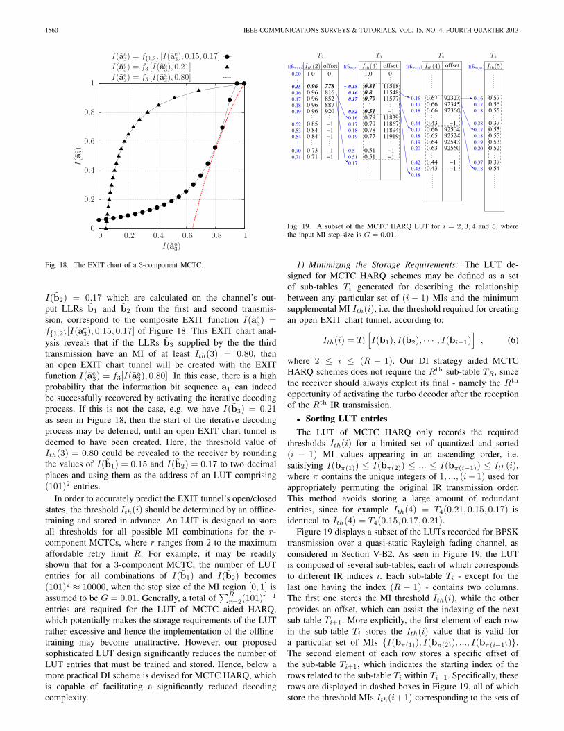
Figure 18 illustrates the EXIT chart of a 3-componentMCTC, which is drawn using the partitioning method in-troduced in Section IV-B. The MIs I(b1) = 0.15 and
1560 IEEE COMMUNICATIONS SURVEYS & TUTORIALS, VOL. 15, NO. 4, FOURTH QUARTER 2013
I(ae3) = f3 [I(aa
3), 0.80]
I(ae3) = f3 [I(aa
3), 0.21]
I(aa3) = f{1,2} [I(ae
3), 0.15, 0.17]
I(aa3)
I(a
e 3)
10.80.60.40.20
1
0.8
0.6
0.4
0.2
0
Fig. 18. The EXIT chart of a 3-component MCTC.
I(b2) = 0.17 which are calculated on the channel’s out-put LLRs b1 and b2 from the first and second transmis-sion, correspond to the composite EXIT function I(aa3) =f{1,2}[I(a
e3), 0.15, 0.17] of Figure 18. This EXIT chart anal-
ysis reveals that if the LLRs b3 supplied by the the thirdtransmission have an MI of at least Ith(3) = 0.80, thenan open EXIT chart tunnel will be created with the EXITfunction I(ae3) = f3[I(a
a3), 0.80]. In this case, there is a high
probability that the information bit sequence a1 can indeedbe successfully recovered by activating the iterative decodingprocess. If this is not the case, e.g. we have I(b3) = 0.21as seen in Figure 18, then the start of the iterative decodingprocess may be deferred, until an open EXIT chart tunnel isdeemed to have been created. Here, the threshold value ofIth(3) = 0.80 could be revealed to the receiver by roundingthe values of I(b1) = 0.15 and I(b2) = 0.17 to two decimalplaces and using them as the address of an LUT comprising(101)2 entries.
In order to accurately predict the EXIT tunnel’s open/closedstates, the threshold Ith(i) should be determined by an offline-training and stored in advance. An LUT is designed to storeall thresholds for all possible MI combinations for the r-component MCTCs, where r ranges from 2 to the maximumaffordable retry limit R. For example, it may be readilyshown that for a 3-component MCTC, the number of LUTentries for all combinations of I(b1) and I(b2) becomes(101)2 ≈ 10000, when the step size of the MI region [0, 1] isassumed to be G = 0.01. Generally, a total of
∑Rr=2(101)
r−1
entries are required for the LUT of MCTC aided HARQ,which potentially makes the storage requirements of the LUTrather excessive and hence the implementation of the offline-training may become unattractive. However, our proposedsophisticated LUT design significantly reduces the number ofLUT entries that must be trained and stored. Hence, below amore practical DI scheme is devised for MCTC HARQ, whichis capable of facilitating a significantly reduced decodingcomplexity.
offset0
118671189411919
1.0
1151811548
11839−1
−1−1
9232392345
offset
92504
92366
925249254392560
−1
−1
−1
0.810.80.79
0.510.790.790.780.77
0.510.51
0.16
0.17
0.52
0.510.5
0.16
0.170.180.19
0.17
0.17
0.180.19
0.670.160.66
0.18 0.66
0.430.66
0.44
0.650.64
0.20 0.63
0.440.43
0.18
0.420.43
0.170.18
0.180.190.20
0.370.18
0.16 0.570.56
0.370.17 0.55
0.550.530.52
0.370.54
offset01.0
7780.960.96
816
0.960.96 920
−1
−1
−1−10.85
0.840.84
0.73−10.71
0.530.54
0.52
0.700.71
0.160.17
0.190.18
0.00
0.55
0.960.15 0.15
852887
11577
0.170.38
T4 T5T2 T3
Ith(3) Ith(4) Ith(5)Ith(2) I(bπ(3)) I(bπ(4))I(bπ(1)) I(bπ(2))
Fig. 19. A subset of the MCTC HARQ LUT for i = 2, 3, 4 and 5, wherethe input MI step-size is G = 0.01.
1) Minimizing the Storage Requirements: The LUT de-signed for MCTC HARQ schemes may be defined as a setof sub-tables Ti generated for describing the relationshipbetween any particular set of (i − 1) MIs and the minimumsupplemental MI Ith(i), i.e. the threshold required for creatingan open EXIT chart tunnel, according to:
Ith(i) = Ti
[I(b1), I(b2), · · · , I(bi−1)
], (6)
where 2 ≤ i ≤ (R − 1). Our DI strategy aided MCTCHARQ schemes does not require the Rth sub-table TR, sincethe receiver should always exploit its final - namely the Rth
opportunity of activating the turbo decoder after the receptionof the Rth IR transmission.
• Sorting LUT entriesThe LUT of MCTC HARQ only records the required
thresholds Ith(i) for a limited set of quantized and sorted(i − 1) MI values appearing in an ascending order, i.e.satisfying I(bπ(1)) ≤ I(bπ(2)) ≤ ... ≤ I(bπ(i−1)) ≤ Ith(i),where π contains the unique integers of 1, ..., (i− 1) used forappropriately permuting the original IR transmission order.This method avoids storing a large amount of redundantentries, since for example Ith(4) = T4(0.21, 0.15, 0.17) isidentical to Ith(4) = T4(0.15, 0.17, 0.21).
Figure 19 displays a subset of the LUTs recorded for BPSKtransmission over a quasi-static Rayleigh fading channel, asconsidered in Section V-B2. As seen in Figure 19, the LUTis composed of several sub-tables, each of which correspondsto different IR indices i. Each sub-table Ti - except for thelast one having the index (R − 1) - contains two columns.The first one stores the MI threshold Ith(i), while the otherprovides an offset, which can assist the indexing of the nextsub-table Ti+1. More explicitly, the first element of each rowin the sub-table Ti stores the Ith(i) value that is valid fora particular set of MIs {I(bπ(1)), I(bπ(2)), ..., I(bπ(i−1))}.The second element of each row stores a specific offset ofthe sub-table Ti+1, which indicates the starting index of therows related to the sub-table Ti within Ti+1. Specifically, theserows are displayed in dashed boxes in Figure 19, all of whichstore the threshold MIs Ith(i+1) corresponding to the sets of
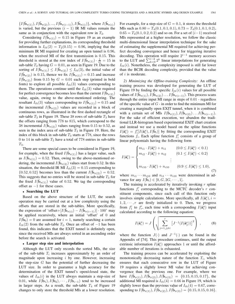
CHEN et al.: A SURVEY AND TUTORIAL ON LOW-COMPLEXITY TURBO CODING TECHNIQUES AND A HOLISTIC HYBRID ARQ DESIGN EXAMPLE 1561
{I(bπ(1)), I(bπ(2)), ..., I(bπ(i−1)), I(bπ(i))}, where I(bπ(i))is varied, but the previous (i − 1) IR MI values remain thesame as in conjunction with the equivalent row in T2.
Considering I(bπ(1)) = 0.15 in Figure 19 as an examplefor providing further explanations, its corresponding thresholdinformation is Ith(2) = T2(0.15) = 0.96, implying that theminimum IR MI required for creating an open tunnel is 0.96,when the received MI of the first transmission is 0.15. Thisthreshold is stored at the row index of I(bπ(1)) · 1
G = 15 insub-table T2 having G = 0.01, as seen in Figure 19. Due to thesorting of I(bπ(1)) ≤ I(bπ(2)) ≤ Ith(3), the initial value ofI(bπ(2)) is 0.15, thence we fix I(bπ(1)) = 0.15 and increaseI(bπ(2)) from 0.15 by G = 0.01 each step (printed in boldfonts) to explore all possible Ith(3) values corresponding tothem. The operations continue until the Ith(3) value requiredfor perfect convergence becomes less than the current I(bπ(2))value, again, owing to the above-mentioned ordering. Theresultant Ith(3) values corresponding to I(bπ(1)) = 0.15 andthe incremental I(bπ(2)) values are recorded in a block ofcontinuous rows, as illustrated in the first dashed rectangle ofsub-table T3 in Figure 19. These 38 rows of sub-table T3 havethe offsets ranging from 778 to 815, which correspond to the38 incremental I(bπ(2)) values ranging from 0.15 to 0.52, asseen in the index area of sub-table T3 in Figure 19. Here, theindex of this block in sub-table T3 starts at 778, since the rows0 to 14 in sub-table T2 have a total of 778 entries in sub-tableT3.
There are some special cases to be considered in Figure 19,for example, when the fixed I(bπ(1)) has a larger value, suchas I(bπ(1)) = 0.52. Then, owing to the above-mentioned or-dering, the incremental I(bπ(2)) values start from 0.52. In thissituation, the threshold IR MI Ith(3) = 0.15 corresponding to{0.52, 0.52} becomes less than the current I(bπ(2)) = 0.52.This suggests that no entries will be stored in sub-table T3 forthe fixed I(bπ(1)) value of 0.52. We tag the correspondingoffset as −1 for these cases.
• Searching the LUTBased on the above structure of the LUT, the search
operation may be carried out at a low complexity using theoffsets that are stored in the sub-tables. More specifically,the expression of ‘offset+[I(bπ(i)) − I(bπ(i−1))] · 100’ maybe applied recursively, where an initial ‘offset’ of 0 andI(b0) = 0 are assumed for i = 1, namely searching a certainIth(2) from the sub-table T2. Once an offset of −1 has beenfound, this indicates that the EXIT tunnel is definitely open,since the received MIs are always sorted in an ascending orderbefore the search is activated.
• Larger step size and interpolationAlthough the LUT only records the sorted MIs, the size
of the sub-table Ti increases approximately by an order ofmagnitude upon increasing i by one. However, increasingthe step-size G has the potential of further decreasing theLUT size. In order to guarantee a high accuracy for thedetermination of the EXIT tunnel’s open/closed state, thevalues of Ith(i) in the LUT always maintain a step-size of0.01, while I(b1), I(b2), · · · , I(bi−1) tend to be increasedin larger steps. As a result, the sub-table T4 of Figure 19changes to only store the threshold MIs at a lower resolution.
For example, for a step-size of G = 0.1, it stores the thresholdMIs such as 0.80 = T4(0.1, 0.1, 0.1), 0.73 = T4(0.1, 0.1, 0.2),0.65 = T4(0.1, 0.2, 0.2) and so on. For a set of (i−1) receivedMIs represented at a higher resolution, we follow the classicmulti-dimensional linear interpolation technique for the sakeof estimating the supplemental MI required for achieving per-fect decoding convergence and hence for triggering iterativedecoding. This operation will require 2i−1 memory accessesto the LUT and
∑i−2k=0 2
k linear interpolations for generatingIth(i). Nonetheless, the complexity imposed is still far lowerthan the BCJR decoding complexity, provided that the valueof i is moderate.
2) Minimizing the Offline-training Complexity: An offlinetraining process was developed for generating the LUT ofFigure 19 by finding the specific Ith(i) values for all possiblevalues of I(bπ(1)), I(bπ(2)) . . . I(bπ(i−1)). This process scansthrough the entire input MI range in steps of 0.01 - regardlessof the specific value of G - in order to find the minimum MI forcreating a marginally open EXIT tunnel, when it is combinedwith a certain set of MIs I(bπ(1)), I(bπ(2)) . . . I(bπ(i−1)).For the sake of efficient execution, we abandon the tradi-tional LLR-histogram based experimental EXIT chart creationand instead we use a model based on the spline functionsI(aei ) = f ′
i [I(aai ), I(bi)] by fitting the corresponding EXIT
functions fi. Each spline function f ′i consists of a group of
linear polynomials having the following form
I(aei ) =
⎧⎪⎪⎪⎪⎨⎪⎪⎪⎪⎩
mi1 · I(aai ) + ni1 (0.0 ≤ I(aai ) < 0.1)
mi2 · I(aai ) + ni2 (0.1 ≤ I(aai ) < 0.2)...
mi10 · I(aai ) + ni10 (0.9 ≤ I(aai ) ≤ 1.0),(7)
where mi1 · · ·mi10 and ni1 · · ·ni10 were determined in ad-vance for any I(bi) ∈ [0, G, 2G, · · · , 1].
The training is accelerated by iteratively invoking r splinefunctions f ′
i corresponding to the MCTC decoder’s r con-stituent components, since each call of this function onlyinvolves simple calculations. More specifically, all I(aei ), i =1, 2, · · · , r are firstly initialized to 0. Then, we progressfrom f ′
1 to f ′r, each time with a corresponding I(aai ) input
calculated according to the following equation:
I(aai ) = J
⎛⎝√√√√ r∑
j=1,j �=i
[J−1(I(aej))
]2⎞⎠ , (8)
where the function J(·) and J−1(·) can be found in theAppendix of [74]. This procedure continues, until the outputextrinsic information I(aei ) approaches 1 or until the afford-able number of iterations is exhausted.
The training process can be accelerated by exploiting themonotonically decreasing nature of the function Ti, whichensures that each consecutive row in the LUT of Figure19 requires a slightly lower MI value for achieving con-vergence than the previous one. For example, where wehave I(bπ(1)), I(bπ(2)), I(bπ(3)) = {0.15, 0.15, 0.17}, theadditional MI required is Ith(4) = 0.66 in Figure 19, which isslightly lower than the previous value of Ith(4) = 0.67, corre-sponding to I(bπ(1)), I(bπ(2)), I(bπ(3)) = {0.15, 0.15, 0.16}.
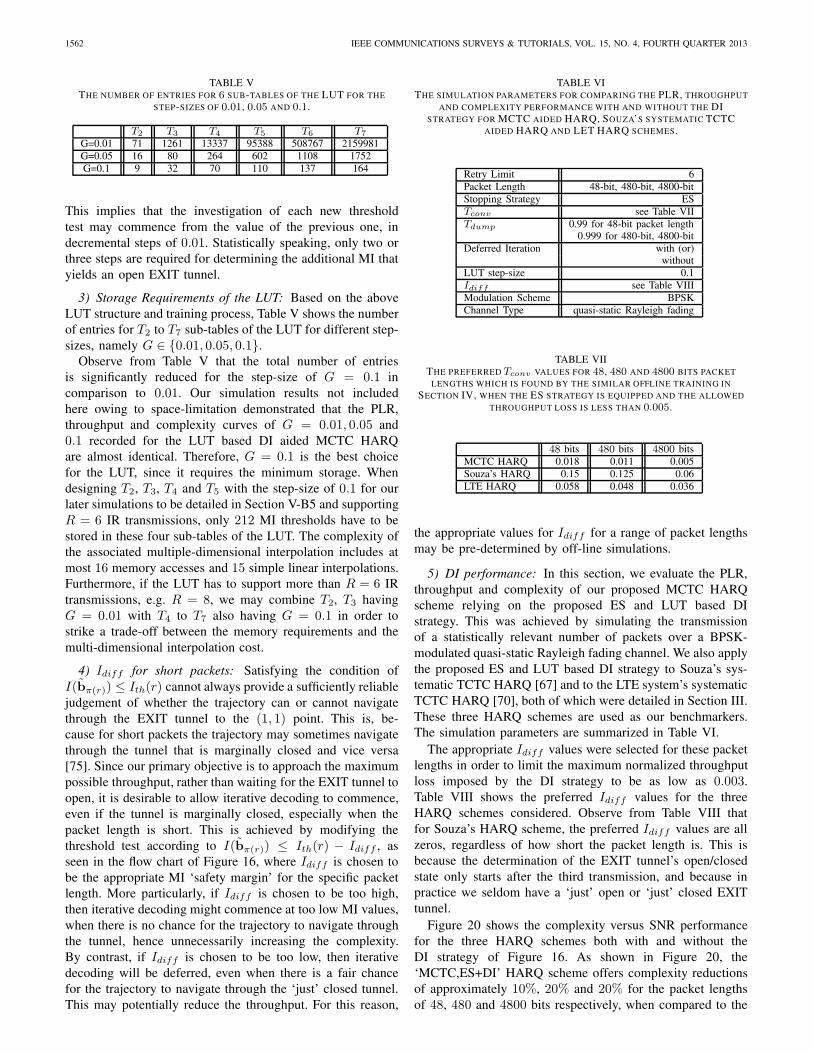
1562 IEEE COMMUNICATIONS SURVEYS & TUTORIALS, VOL. 15, NO. 4, FOURTH QUARTER 2013
TABLE VTHE NUMBER OF ENTRIES FOR 6 SUB-TABLES OF THE LUT FOR THE
STEP-SIZES OF 0.01, 0.05 AND 0.1.
T2 T3 T4 T5 T6 T7
G=0.01 71 1261 13337 95388 508767 2159981G=0.05 16 80 264 602 1108 1752G=0.1 9 32 70 110 137 164
This implies that the investigation of each new thresholdtest may commence from the value of the previous one, indecremental steps of 0.01. Statistically speaking, only two orthree steps are required for determining the additional MI thatyields an open EXIT tunnel.
3) Storage Requirements of the LUT: Based on the aboveLUT structure and training process, Table V shows the numberof entries for T2 to T7 sub-tables of the LUT for different step-sizes, namely G ∈ {0.01, 0.05, 0.1}.
Observe from Table V that the total number of entriesis significantly reduced for the step-size of G = 0.1 incomparison to 0.01. Our simulation results not includedhere owing to space-limitation demonstrated that the PLR,throughput and complexity curves of G = 0.01, 0.05 and0.1 recorded for the LUT based DI aided MCTC HARQare almost identical. Therefore, G = 0.1 is the best choicefor the LUT, since it requires the minimum storage. Whendesigning T2, T3, T4 and T5 with the step-size of 0.1 for ourlater simulations to be detailed in Section V-B5 and supportingR = 6 IR transmissions, only 212 MI thresholds have to bestored in these four sub-tables of the LUT. The complexity ofthe associated multiple-dimensional interpolation includes atmost 16 memory accesses and 15 simple linear interpolations.Furthermore, if the LUT has to support more than R = 6 IRtransmissions, e.g. R = 8, we may combine T2, T3 havingG = 0.01 with T4 to T7 also having G = 0.1 in order tostrike a trade-off between the memory requirements and themulti-dimensional interpolation cost.
4) Idiff for short packets: Satisfying the condition ofI(bπ(r)) ≤ Ith(r) cannot always provide a sufficiently reliablejudgement of whether the trajectory can or cannot navigatethrough the EXIT tunnel to the (1, 1) point. This is, be-cause for short packets the trajectory may sometimes navigatethrough the tunnel that is marginally closed and vice versa[75]. Since our primary objective is to approach the maximumpossible throughput, rather than waiting for the EXIT tunnel toopen, it is desirable to allow iterative decoding to commence,even if the tunnel is marginally closed, especially when thepacket length is short. This is achieved by modifying thethreshold test according to I(bπ(r)) ≤ Ith(r) − Idiff , asseen in the flow chart of Figure 16, where Idiff is chosen tobe the appropriate MI ‘safety margin’ for the specific packetlength. More particularly, if Idiff is chosen to be too high,then iterative decoding might commence at too low MI values,when there is no chance for the trajectory to navigate throughthe tunnel, hence unnecessarily increasing the complexity.By contrast, if Idiff is chosen to be too low, then iterativedecoding will be deferred, even when there is a fair chancefor the trajectory to navigate through the ‘just’ closed tunnel.This may potentially reduce the throughput. For this reason,
TABLE VITHE SIMULATION PARAMETERS FOR COMPARING THE PLR, THROUGHPUT
AND COMPLEXITY PERFORMANCE WITH AND WITHOUT THE DISTRATEGY FOR MCTC AIDED HARQ, SOUZA’S SYSTEMATIC TCTC
AIDED HARQ AND LET HARQ SCHEMES.
Retry Limit 6Packet Length 48-bit, 480-bit, 4800-bitStopping Strategy ESTconv see Table VIITdump 0.99 for 48-bit packet length
0.999 for 480-bit, 4800-bitDeferred Iteration with (or)
withoutLUT step-size 0.1Idiff see Table VIIIModulation Scheme BPSKChannel Type quasi-static Rayleigh fading
TABLE VIITHE PREFERRED Tconv VALUES FOR 48, 480 AND 4800 BITS PACKET
LENGTHS WHICH IS FOUND BY THE SIMILAR OFFLINE TRAINING INSECTION IV, WHEN THE ES STRATEGY IS EQUIPPED AND THE ALLOWED
THROUGHPUT LOSS IS LESS THAN 0.005.
48 bits 480 bits 4800 bitsMCTC HARQ 0.018 0.011 0.005Souza’s HARQ 0.15 0.125 0.06LTE HARQ 0.058 0.048 0.036
the appropriate values for Idiff for a range of packet lengthsmay be pre-determined by off-line simulations.
5) DI performance: In this section, we evaluate the PLR,throughput and complexity of our proposed MCTC HARQscheme relying on the proposed ES and LUT based DIstrategy. This was achieved by simulating the transmissionof a statistically relevant number of packets over a BPSK-modulated quasi-static Rayleigh fading channel. We also applythe proposed ES and LUT based DI strategy to Souza’s sys-tematic TCTC HARQ [67] and to the LTE system’s systematicTCTC HARQ [70], both of which were detailed in Section III.These three HARQ schemes are used as our benchmarkers.The simulation parameters are summarized in Table VI.
The appropriate Idiff values were selected for these packetlengths in order to limit the maximum normalized throughputloss imposed by the DI strategy to be as low as 0.003.Table VIII shows the preferred Idiff values for the threeHARQ schemes considered. Observe from Table VIII thatfor Souza’s HARQ scheme, the preferred Idiff values are allzeros, regardless of how short the packet length is. This isbecause the determination of the EXIT tunnel’s open/closedstate only starts after the third transmission, and because inpractice we seldom have a ‘just’ open or ‘just’ closed EXITtunnel.
Figure 20 shows the complexity versus SNR performancefor the three HARQ schemes both with and without theDI strategy of Figure 16. As shown in Figure 20, the‘MCTC,ES+DI’ HARQ scheme offers complexity reductionsof approximately 10%, 20% and 20% for the packet lengthsof 48, 480 and 4800 bits respectively, when compared to the
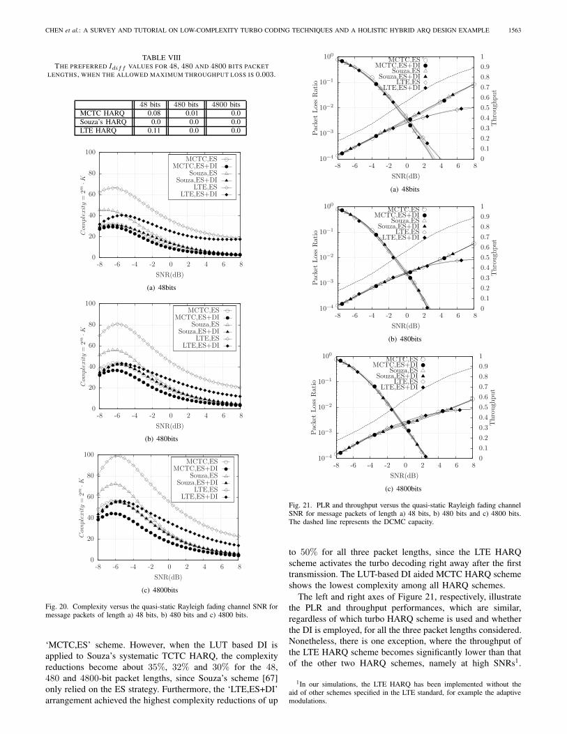
CHEN et al.: A SURVEY AND TUTORIAL ON LOW-COMPLEXITY TURBO CODING TECHNIQUES AND A HOLISTIC HYBRID ARQ DESIGN EXAMPLE 1563
TABLE VIIITHE PREFERRED Idiff VALUES FOR 48, 480 AND 4800 BITS PACKET
LENGTHS, WHEN THE ALLOWED MAXIMUM THROUGHPUT LOSS IS 0.003.
48 bits 480 bits 4800 bitsMCTC HARQ 0.08 0.01 0.0Souza’s HARQ 0.0 0.0 0.0LTE HARQ 0.11 0.0 0.0
LTE,ES+DILTE,ES
Souza,ES+DISouza,ES
MCTC,ES+DIMCTC,ES
SNR(dB)
Com
plex
ity
=2m
·K
86420-2-4-6-8
100
80
60
40
20
0
(a) 48bits
LTE,ES+DILTE,ES
Souza,ES+DISouza,ES
MCTC,ES+DIMCTC,ES
SNR(dB)
Com
plex
ity
=2m
·K
86420-2-4-6-8
100
80
60
40
20
0
(b) 480bits
LTE,ES+DILTE,ES
Souza,ES+DISouza,ES
MCTC,ES+DIMCTC,ES
SNR(dB)
Com
plex
ity
=2m
·K
86420-2-4-6-8
100
80
60
40
20
0
(c) 4800bits
Fig. 20. Complexity versus the quasi-static Rayleigh fading channel SNR formessage packets of length a) 48 bits, b) 480 bits and c) 4800 bits.
‘MCTC,ES’ scheme. However, when the LUT based DI isapplied to Souza’s systematic TCTC HARQ, the complexityreductions become about 35%, 32% and 30% for the 48,480 and 4800-bit packet lengths, since Souza’s scheme [67]only relied on the ES strategy. Furthermore, the ‘LTE,ES+DI’arrangement achieved the highest complexity reductions of up
LTE,ES+DILTE,ES
Souza,ES+DISouza,ES
MCTC,ES+DIMCTC,ES
SNR(dB)
Thr
ough
put
Pac
ket
Los
sR
atio
10.90.80.70.60.50.40.30.20.10
86420-2-4-6-8
100
10−1
10−2
10−3
10−4
(a) 48bits
LTE,ES+DILTE,ES
Souza,ES+DISouza,ES
MCTC,ES+DIMCTC,ES
SNR(dB)
Thr
ough
put
Pac
ket
Los
sR
atio
10.90.80.70.60.50.40.30.20.10
86420-2-4-6-8
100
10−1
10−2
10−3
10−4
(b) 480bits
LTE,ES+DILTE,ES
Souza,ES+DISouza,ES
MCTC,ES+DIMCTC,ES
SNR(dB)
Thr
ough
put
Pac
ket
Los
sR
atio
10.90.80.70.60.50.40.30.20.10
86420-2-4-6-8
100
10−1
10−2
10−3
10−4
(c) 4800bits
Fig. 21. PLR and throughput versus the quasi-static Rayleigh fading channelSNR for message packets of length a) 48 bits, b) 480 bits and c) 4800 bits.The dashed line represents the DCMC capacity.
to 50% for all three packet lengths, since the LTE HARQscheme activates the turbo decoding right away after the firsttransmission. The LUT-based DI aided MCTC HARQ schemeshows the lowest complexity among all HARQ schemes.
The left and right axes of Figure 21, respectively, illustratethe PLR and throughput performances, which are similar,regardless of which turbo HARQ scheme is used and whetherthe DI is employed, for all the three packet lengths considered.Nonetheless, there is one exception, where the throughput ofthe LTE HARQ scheme becomes significantly lower than thatof the other two HARQ schemes, namely at high SNRs1.
1In our simulations, the LTE HARQ has been implemented without theaid of other schemes specified in the LTE standard, for example the adaptivemodulations.
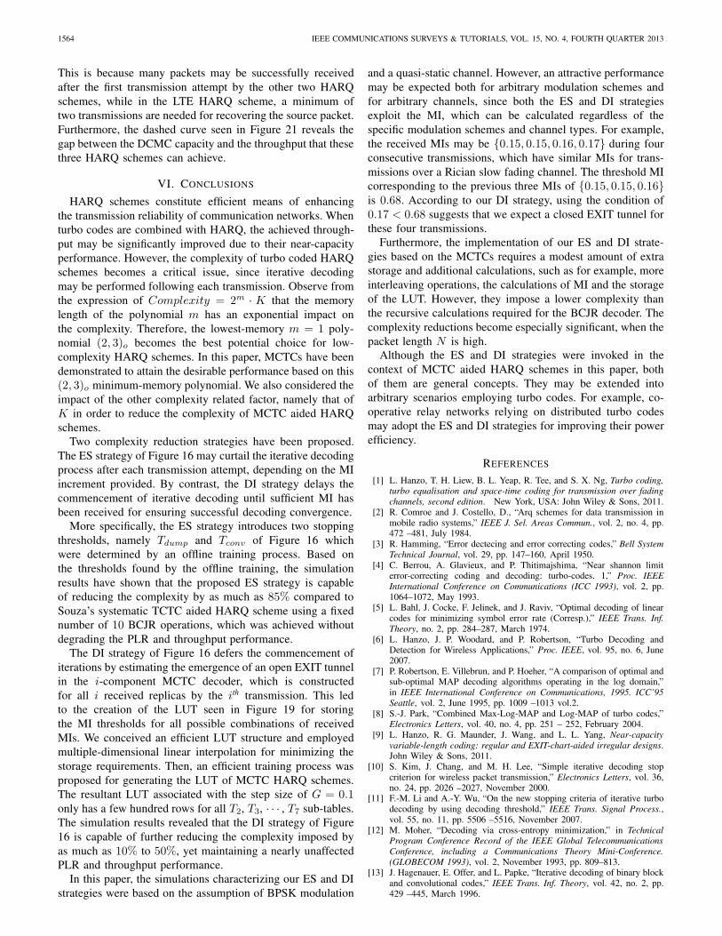
1564 IEEE COMMUNICATIONS SURVEYS & TUTORIALS, VOL. 15, NO. 4, FOURTH QUARTER 2013
This is because many packets may be successfully receivedafter the first transmission attempt by the other two HARQschemes, while in the LTE HARQ scheme, a minimum oftwo transmissions are needed for recovering the source packet.Furthermore, the dashed curve seen in Figure 21 reveals thegap between the DCMC capacity and the throughput that thesethree HARQ schemes can achieve.
VI. CONCLUSIONS
HARQ schemes constitute efficient means of enhancingthe transmission reliability of communication networks. Whenturbo codes are combined with HARQ, the achieved through-put may be significantly improved due to their near-capacityperformance. However, the complexity of turbo coded HARQschemes becomes a critical issue, since iterative decodingmay be performed following each transmission. Observe fromthe expression of Complexity = 2m · K that the memorylength of the polynomial m has an exponential impact onthe complexity. Therefore, the lowest-memory m = 1 poly-nomial (2, 3)o becomes the best potential choice for low-complexity HARQ schemes. In this paper, MCTCs have beendemonstrated to attain the desirable performance based on this(2, 3)o minimum-memory polynomial. We also considered theimpact of the other complexity related factor, namely that ofK in order to reduce the complexity of MCTC aided HARQschemes.
Two complexity reduction strategies have been proposed.The ES strategy of Figure 16 may curtail the iterative decodingprocess after each transmission attempt, depending on the MIincrement provided. By contrast, the DI strategy delays thecommencement of iterative decoding until sufficient MI hasbeen received for ensuring successful decoding convergence.
More specifically, the ES strategy introduces two stoppingthresholds, namely Tdump and Tconv of Figure 16 whichwere determined by an offline training process. Based onthe thresholds found by the offline training, the simulationresults have shown that the proposed ES strategy is capableof reducing the complexity by as much as 85% compared toSouza’s systematic TCTC aided HARQ scheme using a fixednumber of 10 BCJR operations, which was achieved withoutdegrading the PLR and throughput performance.
The DI strategy of Figure 16 defers the commencement ofiterations by estimating the emergence of an open EXIT tunnelin the i-component MCTC decoder, which is constructedfor all i received replicas by the ith transmission. This ledto the creation of the LUT seen in Figure 19 for storingthe MI thresholds for all possible combinations of receivedMIs. We conceived an efficient LUT structure and employedmultiple-dimensional linear interpolation for minimizing thestorage requirements. Then, an efficient training process wasproposed for generating the LUT of MCTC HARQ schemes.The resultant LUT associated with the step size of G = 0.1only has a few hundred rows for all T2, T3, · · · , T7 sub-tables.The simulation results revealed that the DI strategy of Figure16 is capable of further reducing the complexity imposed byas much as 10% to 50%, yet maintaining a nearly unaffectedPLR and throughput performance.
In this paper, the simulations characterizing our ES and DIstrategies were based on the assumption of BPSK modulation
and a quasi-static channel. However, an attractive performancemay be expected both for arbitrary modulation schemes andfor arbitrary channels, since both the ES and DI strategiesexploit the MI, which can be calculated regardless of thespecific modulation schemes and channel types. For example,the received MIs may be {0.15, 0.15, 0.16, 0.17} during fourconsecutive transmissions, which have similar MIs for trans-missions over a Rician slow fading channel. The threshold MIcorresponding to the previous three MIs of {0.15, 0.15, 0.16}is 0.68. According to our DI strategy, using the condition of0.17 < 0.68 suggests that we expect a closed EXIT tunnel forthese four transmissions.
Furthermore, the implementation of our ES and DI strate-gies based on the MCTCs requires a modest amount of extrastorage and additional calculations, such as for example, moreinterleaving operations, the calculations of MI and the storageof the LUT. However, they impose a lower complexity thanthe recursive calculations required for the BCJR decoder. Thecomplexity reductions become especially significant, when thepacket length N is high.
Although the ES and DI strategies were invoked in thecontext of MCTC aided HARQ schemes in this paper, bothof them are general concepts. They may be extended intoarbitrary scenarios employing turbo codes. For example, co-operative relay networks relying on distributed turbo codesmay adopt the ES and DI strategies for improving their powerefficiency.
REFERENCES
[1] L. Hanzo, T. H. Liew, B. L. Yeap, R. Tee, and S. X. Ng, Turbo coding,turbo equalisation and space-time coding for transmission over fadingchannels, second edition. New York, USA: John Wiley & Sons, 2011.
[2] R. Comroe and J. Costello, D., “Arq schemes for data transmission inmobile radio systems,” IEEE J. Sel. Areas Commun., vol. 2, no. 4, pp.472 –481, July 1984.
[3] R. Hamming, “Error dectecing and error correcting codes,” Bell SystemTechnical Journal, vol. 29, pp. 147–160, April 1950.
[4] C. Berrou, A. Glavieux, and P. Thitimajshima, “Near shannon limiterror-correcting coding and decoding: turbo-codes. 1,” Proc. IEEEInternational Conference on Communications (ICC 1993), vol. 2, pp.1064–1072, May 1993.
[5] L. Bahl, J. Cocke, F. Jelinek, and J. Raviv, “Optimal decoding of linearcodes for minimizing symbol error rate (Corresp.),” IEEE Trans. Inf.Theory, no. 2, pp. 284–287, March 1974.
[6] L. Hanzo, J. P. Woodard, and P. Robertson, “Turbo Decoding andDetection for Wireless Applications,” Proc. IEEE, vol. 95, no. 6, June2007.
[7] P. Robertson, E. Villebrun, and P. Hoeher, “A comparison of optimal andsub-optimal MAP decoding algorithms operating in the log domain,”in IEEE International Conference on Communications, 1995. ICC’95Seattle, vol. 2, June 1995, pp. 1009 –1013 vol.2.
[8] S.-J. Park, “Combined Max-Log-MAP and Log-MAP of turbo codes,”Electronics Letters, vol. 40, no. 4, pp. 251 – 252, February 2004.
[9] L. Hanzo, R. G. Maunder, J. Wang, and L. L. Yang, Near-capacityvariable-length coding: regular and EXIT-chart-aided irregular designs.John Wiley & Sons, 2011.
[10] S. Kim, J. Chang, and M. H. Lee, “Simple iterative decoding stopcriterion for wireless packet transmission,” Electronics Letters, vol. 36,no. 24, pp. 2026 –2027, November 2000.
[11] F.-M. Li and A.-Y. Wu, “On the new stopping criteria of iterative turbodecoding by using decoding threshold,” IEEE Trans. Signal Process.,vol. 55, no. 11, pp. 5506 –5516, November 2007.
[12] M. Moher, “Decoding via cross-entropy minimization,” in TechnicalProgram Conference Record of the IEEE Global TelecommunicationsConference, including a Communications Theory Mini-Conference.(GLOBECOM 1993), vol. 2, November 1993, pp. 809–813.
[13] J. Hagenauer, E. Offer, and L. Papke, “Iterative decoding of binary blockand convolutional codes,” IEEE Trans. Inf. Theory, vol. 42, no. 2, pp.429 –445, March 1996.
CHEN et al.: A SURVEY AND TUTORIAL ON LOW-COMPLEXITY TURBO CODING TECHNIQUES AND A HOLISTIC HYBRID ARQ DESIGN EXAMPLE 1565
[14] J. Chen, L. Zhang, and J. Qin, “Average-entropy variation in iterativedecoding of turbo codes and its application,” Electronics Letters, vol. 44,no. 22, pp. 1314 –1315, 23 2008.
[15] R. Y. Shao, S. Lin, and M. P. C. Fossorier, “Two simple stopping criteriafor turbo decoding,” IEEE Trans. Commun., vol. 47, no. 8, pp. 1117 –1120, August 1999.
[16] Y. Wu, B. Woerner, and W. Ebel, “A simple stopping criterion for turbodecoding,” IEEE Commun. Lett., vol. 4, no. 8, pp. 258 –260, August2000.
[17] N. Y. Yu, M. G. Kim, Y. S. Kim, and S. U. Chung, “Efficient stoppingcriterion for iterative decoding of turbo codes,” Electronics Letters,vol. 39, no. 1, pp. 73 – 75, January 2003.
[18] F. Q. Zhai and I. J. Fair, “Techniques for early stopping and errordetection in turbo decoding,” IEEE Trans. Commun., vol. 51, no. 10,pp. 1617 – 1623, October 2003.
[19] A. Taffin, “Generalised stopping criterion for iterative decoders,” Elec-tronics Letters, vol. 39, no. 13, pp. 993 – 994, June 2003.
[20] T. Ngatched and F. Takawira, “Simple stopping criterion for turbodecoding,” Electronics Letters, vol. 37, no. 22, pp. 1350 –1351, October2001.
[21] A. Shibutani, H. Suda, and F. Adachi, “Reducing average number ofturbo decoding iterations,” Electronics Letters, vol. 35, no. 9, pp. 701–702, April 1999.
[22] Z. Ma, W. H. Mow, and P. Fan, “On the complexity reduction of turbodecoding for wideband cdma,” IEEE Trans. Wireless Commun.,, vol. 4,no. 2, pp. 353 – 356, March 2005.
[23] G. T. Chen, L. Cao, L. Yu, and C. W. Chen, “An efficient stoppingcriterion for turbo product codes,” IEEE Commun. Lett., vol. 11, no. 6,pp. 525 –527, June 2007.
[24] W. Zhanji, P. Mugen, and W. Wenbo, “A new parity-check stoppingcriterion for turbo decoding,” IEEE Commun. Lett., vol. 12, no. 4, pp.304 –306, April 2008.
[25] M. Rovini and A. Martinez, “Efficient stopping rule for turbo decoders,”Electronics Letters, vol. 42, no. 4, pp. 235 – 236, February 2006.
[26] D. H. Kim and S. Kim, “Bit-level stopping of turbo decoding,” IEEECommun. Lett., vol. 10, no. 3, pp. 183 – 185, March 2006.
[27] J. Wu, Z. Wang, and B. Vojcic, “Partial iterative decoding for binaryturbo codes via cross-entropy based bit selection,” IEEE Trans. Com-munications, vol. 57, no. 11, pp. 3298 –3306, November 2009.
[28] W. Shao and L. Brackenbury, “Early stopping turbo decoders: a high-throughput, low-energy bit-level approach and implementation,” Com-munications, IET, vol. 4, no. 17, pp. 2115 –2124, November 2010.
[29] M. W. Williard, “Introduction to redundancy coding,” IEEE Trans. Veh.Technol., vol. 27, no. 3, pp. 86–98, August 1978.
[30] E. Y. Rocher and R. L. Pickholtz, “An analysis of the effectiveness ofhybrid transmission schemes,” IBM Journal of Research and Develop-ment, vol. 14, no. 4, pp. 426 –433, July 1970.
[31] H. O. Burton and D. D. Sullivan, “Errors and error control,” Proc. IEEE,vol. 60, no. 11, pp. 1293–1301, November 1972.
[32] S. Lin and P. Yu, “A hybrid ARQ scheme with parity retransmissionfor error control of satellite channels,” IEEE Trans. Commun., vol. 30,no. 7, pp. 1701–1719, July 1982.
[33] A. Sastry, “Performance of hybrid error control schemes of satellitechannels,” IEEE Trans. Commun., vol. 23, no. 7, pp. 689–694, July1975.
[34] A. Sastry and L. Kanal, “Hybrid error control using retransmission andgeneralized burst-trapping codes,” IEEE Trans. Commun., vol. 24, no. 4,pp. 385–393, April 1976.
[35] C. Fujiwara, M. Kasahara, K. Yamashita, and T. Namekawa, “Eval-uations of error control techniques in both independent-error anddependent-error channels,” IEEE Trans. Commun., vol. 26, no. 6, pp.785 – 794, June 1978.
[36] A. Drukarev and J. D. J. Costello, “A comparison of block and convo-lutional codes in ARQ error control schemes,” IEEE Trans. Commun.,vol. 30, no. 11, pp. 2449–2455, November 1982.
[37] S. Kallel and D. Haccoun, “Generalized type II hybrid ARQ schemeusing punctured convolutional coding,” IEEE Trans. Commun., vol. 38,no. 11, pp. 1938 –1946, November 1990.
[38] Q. Zhang and S. Kassam, “Hybrid ARQ with selective combining forfading channels,” IEEE J. Sel. Areas Commun., vol. 17, no. 5, pp. 867–880, May 1999.
[39] J. Hagenauer, “Rate-compatible punctured convolutional codes (RCPCcodes) and their applications,” IEEE Trans. Commun., vol. 36, no. 4,pp. 389 –400, April 1988.
[40] S. Kallel, “Complementary punctured convolutional (CPC) codes andtheir applications,” IEEE Trans. Commun., vol. 43, no. 6, pp. 2005–2009, June 1995.
[41] Q. C. Chen and P. Z. Fan, “On the performance of type-III hybrid ARQwith RCPC codes,” in Proc. 14th IEEE on Personal, Indoor and MobileRadio Communications (PIMRC 2003), vol. 2, September 2003, pp.1297–1301.
[42] Y. F. Wang, L. Zhang, and D. C. Yang, “Performance analysis oftype III HARQ with turbo codes,” in Proc. IEEE Vehicular TechnologyConference (VTC 2003-Spring), vol. 4. IEEE, April 2003, pp. 2740–2744.
[43] C. X. Wang, H. G. Ryu, H. H. Chen, and Y. He, “Hybrid ARQwith rate adaptation in multiband OFDM UWB systems,” Proc. IEEEInternational Conference on Communications (ICC 2009), pp. 1–5, June2009.
[44] H. Krishna and S. Morgera, “A new error control scheme for hybridARQ systems,” IEEE Trans. Commun., vol. 35, no. 10, pp. 981 – 990,October 1987.
[45] S. Morgera and V. Oduol, “Soft-decision decoding applied to the gen-eralized type-II hybrid ARQ scheme,” IEEE Trans. Commun., vol. 37,no. 4, pp. 393 –396, April 1989.
[46] M. Kousa and M. Rahman, “An adaptive error control system usinghybrid ARQ schemes,” IEEE Trans. Commun., vol. 39, no. 7, pp. 1049–1057, July 1991.
[47] M. Rice, “Comparative analysis of two realizations for hybrid-ARQerror control,” in Proc. IEEE Global Communications Conference,(GLOBECOM 1994), December 1994, pp. 115 –119.
[48] P. Coulton, C. Tanriover, B. Wright, and B. Honary, “Simple hybrid typeII ARQ technique using soft output information,” Electronics Letters,vol. 36, no. 20, pp. 1716 –1717, September 2000.
[49] M. Buckley and S. Wicker, “The design and performance of a neuralnetwork for predicting turbo decoding error with application to hybridARQ protocols,” IEEE Trans. Commun., vol. 48, no. 4, pp. 566 –576,April 2000.
[50] S. Choi and K. Shin, “A class of adaptive hybrid ARQ schemes forwireless links,” IEEE Trans. Veh. Technol., vol. 50, no. 3, pp. 777 –790,May 2001.
[51] B. Harvey, “Adaptive viterbi algorithm with ARQ for bounded complex-ity decoding,” IEEE Trans. Wireless Commun., vol. 3, no. 6, pp. 1948– 1952, November 2004.
[52] L. Cao and T. Shi, “Turbo codes based hybrid ARQ with segmentselective repeat,” Electronics Letters, vol. 40, no. 18, pp. 1140 – 1141,September 2004.
[53] I. D. Holland, H. J. Zepernick, and M. Caldera, “Soft combining forhybrid ARQ,” IET Electronics Letters, vol. 41, no. 22, pp. 1230–1231,October 2005.
[54] X. Zhang and Q. Du, “Adaptive low-complexity erasure-correcting code-based protocols for QoS-driven mobile multicast services over wirelessnetworks,” IEEE Trans. Veh. Technol., vol. 55, no. 5, pp. 1633 –1647,September 2006.
[55] K. Oteng-Amoako and S. Nooshabadi, “Asymmetric rate compatibleturbo codes in hybrid automatic repeat request schemes,” IEE Proc.Commun.,, vol. 153, no. 5, pp. 603 –610, October 2006.
[56] F. Chiti and R. Fantacci, “A soft combining hybrid-ARQ techniqueapplied to throughput maximization within 3g satellite ip networks,”IEEE Trans. Veh. Technol., vol. 56, no. 2, pp. 594 –604, March 2007.
[57] J. Heo, S. Kim, J. Kim, and J. Kim, “Low complexity decoding forraptor codes for hybrid-ARQ systems,” IEEE Trans. Consum. Electron.,vol. 54, no. 2, pp. 390 –395, May 2008.
[58] B. Mielczarek and W. Krzymien, “Adaptive hybrid ARQ systems withBCJR decoding,” IEEE Trans. Veh. Technol., vol. 57, no. 3, pp. 1606–1619, May 2008.
[59] J. Fricke and P. Hoeher, “Reliability-based retransmission criteria forhybrid ARQ,” IEEE Trans. Commun., vol. 57, no. 8, pp. 2181 –2184,August 2009.
[60] D. Chase, “A combined coding and modulation approach for communi-cation over dispersive channels,” IEEE Trans. Commun., vol. 21, no. 3,pp. 159–174, March 1973.
[61] D. Mandelbaum, “An adaptive-feedback coding scheme using incremen-tal redundancy (corresp.),” IEEE Trans. Inf. Theory, vol. 20, no. 3, pp.388–389, May 1974.
[62] J. N. Laneman, D. N. C. Tse, and G. W. Wornell, “Cooperative diversityin wireless networks: Efficient protocols and outage behavior,” IEEETrans. Inf. Theory, vol. 50, no. 12, pp. 3062–3080, Dec. 2004.
[63] R. H. Liu, P. Spasojevic, and E. Soljanin, “Incremental redundancycooperative coding for wireless networks: Cooperative diversity, coding,and transmission energy gains,” IEEE Trans. Inf. Theory, vol. 54, no. 3,pp. 1207–1224, March 2008.
[64] E. Uhlemann, T. M. Aulin, L. K. Rasmussen, and P. A. Wiberg,“Packet combining and doping in concatenated hybrid ARQ schemes
1566 IEEE COMMUNICATIONS SURVEYS & TUTORIALS, VOL. 15, NO. 4, FOURTH QUARTER 2013
using iterative decoding,” in Proc. IEEE Wireless Communications andNetworking (WCNC 2003), vol. 2, March 2003, pp. 849–854.
[65] 3GPP, “High speed downlink packet access: Physical layer aspects,” TR25.858 V5.0.0, Tech. Rep., March 2002.
[66] K. R. Narayanan and G. L. Stuber, “A novel ARQ technique using theturbo coding principle,” IEEE Commun. Lett., vol. 1, no. 2, pp. 49–51,March 1997.
[67] R. D. Souza, M. E. Pellenz, and T. Rodrigues, “Hybrid ARQ schemebased on recursive convolutional codes and turbo decoding,” IEEETrans. Commun., vol. 57, no. 2, pp. 315–318, February 2009.
[68] T. Ait-Idir, H. Chafnaji, and S. Saoudi, “Turbo packet combiningfor broadband space-time BICM hybrid-ARQ systems with co-channelinterference,” IEEE Trans. Wireless Commun., vol. 9, no. 5, pp. 1686–1697, May 2010.
[69] D. Divsalar, S. Dolinar, and F. Pollara, “Serial concatenated trellis codedmodulation with rate-1 inner code,” in Proceeding of the IEEE GlobalTelecommunications Conference (GLOBECOM 2000), vol. 2, November2000, pp. 777–782.
[70] “3rd Generation Partnership Project; Technical specification group radioaccess network; Evolved Universal Terrestrial Radio Access (E-UTRA);Multiplexing and channel coding (Release 10),” 3GPP TS 36.212, De-cember, 2010, Downloadable at http://www.3gpp.org/FTP/Specs/html-info/26346.htm.
[71] H. Chen, R. G. Maunder, and L. Hanzo, “Multi-level turbo decodingassisted soft combining aided hybrid ARQ,” in Proc. IEEE VehicularTechnology Conference (VTC 2010-Spring), May 2010.
[72] S. ten Brink, “Convergence behavior of iteratively decoded parallelconcatenated codes,” IEEE Trans. Commun., vol. 49, no. 10, pp. 1727–1737, October 2001.
[73] J. Hagenauer, “The EXIT chart - introduction to extrinsic informationtransfer in iterative processing,” in Proc. 12th European Signal Process-ing Conference (EUSIPCO), September 2004, pp. 1541–1548.
[74] S. ten Brink, G. Kramer, and A. Ashikhmin, “Design of low-densityparity-check codes for modulation and detection,” IEEE Trans. Com-mun., vol. 52, no. 4, pp. 670 – 678, April 2004.
[75] J. W. Lee and R. E. Blahut, “Generalized EXIT chart and BER analysisof finite-length turbo codes,” in Proc. IEEE Global CommunicationsConference, (GLOBECOM 2003), vol. 4, December 2003, pp. 2067 –2072.
Hong Chen received her Master Degree in computerscience from University of Electronic Science andTechnology, China in 2000. Since then, she has beena lecturer at UESTC. In November 2007, she startedher PhD study in the Communications ResearchGroup, School of Electronics and Computer Sci-ence, University of Southampton, U.K. Her currentresearch interests include cross-layer optimization ofwireless networks, turbo coding aided hybrid ARQ.Currently she is a postdoctoral research fellow at theUniversity of Surrey, UK.
Robert G. Maunder (MIEEE’03) has studied withthe School of Electronics and Computer Science,University of Southampton, UK, since October2000. He was awarded a first class honours BEngin Electronic Engineering in July 2003, as well as aPh.D. in Wireless Communications and a lectureshipin December 2007, all from University of Southamp-ton, UK. His research interests include video coding,joint source/channel coding and iterative decoding.He has published a number of IEEE papers in theseareas.
Lajos Hanzo (http://www-mobile.ecs.soton.ac.uk)FREng, FIEEE, FIET, Fellow of EURASIP, DScreceived his degree in electronics in 1976 andhis doctorate in 1983. In 2009 he was awardedthe honorary doctorate “Doctor Honaris Causa” bythe Technical University of Budapest. During his35-year career in telecommunications he has heldvarious research and academic posts in Hungary,Germany and the UK. Since 1986 he has been withthe School of Electronics and Computer Science,University of Southampton, UK, where he holds the
chair in telecommunications. He has successfully supervised in excess of70 PhD students, co-authored 20 John Wiley/IEEE Press books on mobileradio communications totalling in excess of 10 000 pages, published 1250+research entries at IEEE Xplore, acted both as TPC and General Chairof IEEE conferences, presented keynote lectures and has been awarded anumber of distinctions. Currently he is directing an academic research team,working on a range of research projects in the field of wireless multimediacommunications sponsored by industry, the Engineering and Physical SciencesResearch Council (EPSRC) UK, the European IST Programme and the MobileVirtual Centre of Excellence (VCE), UK. He is an enthusiastic supporter ofindustrial and academic liaison and he offers a range of industrial courses.He is also a Governor of the IEEE VTS. Since 2008 he has been the Editor-in-Chief of the IEEE Press and since 2009 a Chaired Professor also atTsinghua University, Beijing. For further information on research in progressand associated publications please refer to http://www-mobile.ecs.soton.ac.uk