Embed Size (px)
Citation preview

Hexa Meshing
ANSYS ICEM CFD 11.0 Tutorial Manual
189
4.2.6: Pipe Blade
Overview
This tutorial example uses the “Collapse” function to create a degenerate topology in a Conjugate Heat transfer problem around a blade located in the center of a cylindrical pipe.
a) Summary of Steps
The Blocking Strategy Starting the Project Creating Parts in the Mesh Editor Starting Blocking Using ints to Fit the Blocking
g the Vertices enerating the O-grid
Defining Surface Parameters for the Mesh Defining Edge Parameters to Adjust the Mesh Checking mesh quality for determinants and angle
Prescribed PoSplitting the Topology Using Prescribed Points Collapsing Blocks to Represent the Blade Material Edge to Curve Association on the Blade
ovinMG

Hexa Meshing
ANSYS ICEM CFD 11.0 Tutorial Manual
190
Quitting
g Strategy
In this lesson, the blade is regarded as a Solid region, while the region surrounding the blade is regarded as the Fluid region. Using Block Splitting at “Prescribed point”, the user will generate a Hexahedral Mesh for both of the regions, so that the topology of the solid region is a degenerate ‘Hexahedral’ mesh. Before the user employs the Collapse function for his/her own applications, confirm that the solver accepts degenerated hexas (for a structured solver) or penta_6 elements (prism) for an unstructured solver. Note: Settings >Selection>Auto pick mode should be turned OFF for ANSYS ICEM CFD to behave exactly as this tutorial describes.
c) Starting the Project
The input files for this tutorial can be found in the Ansys installation directory, under ../v110/docu/Tutorials/CFD_Tutorial_Files>PipeBlade. Copy and open the geometry.tin file in your working directory.
d) Creating Parts in the Mesh Editor
s.
Saving before
b) The Blockin
Right click in the Display Tree on Parts > Create Part to create different Parts and assign the different surface of the geometry to the appropriate part. Refer to the figure below for the Surface part assignment

Hexa Meshing
ANSYS ICEM CFD 11.0 Tutorial Manual
191
hePipeBladeconfiguration
Figure4-147 T
e) Surface Parts
fter the Pipe Blade project is open, activate the Points and Surfaces from n Points > Show Points Names.
y
he surfaces belonging to the solid blade in the middle of the cylinder should be classified as BLADE. When all of the Surface parts have been assigned (INLET, OUTLET, CYL, BLADE), press the middle mouse button to exit from continuous mode.
f) Curve Parts and Point Parts
For this tutorial, we will leave the curves and points assigned to the initial part GEOM.
Athe Display Tree. Switch oBegin the Surface part reassignment by changing the region enclosed bGEOM/4 - GEOM/7 to the part OUTLET. The region that is denoted by GEOM/0 - GEOM/3 should be reassigned to the part INLET. The Surface defining the Cylinder pipe will be placed in the Surface part,
YL. CT

Hexa Meshing
ANSYS ICEM CFD 11.0 Tutorial Manual
192
Creating the Material Points
eometry > Create Body
g)
Select G > Material Point
xx
Enter FLUID eate Body window that appears. The material point that will be
reated will help us to keep the FLUID region separate from the SOLID region, but is not necessary since blocks can simply be created in the FLUID part rather than creating a material point. With the left mouse button, select two locations on the opposite sides of the cylinder. Note that the FLUID material point should not be within the BLADE. If tetra meshing, this location would be important. With Hexa meshing, it is not. Press the middle mouse button to accept the selection,
d press Apply and the Body name FLUID should appear within the eometry (midway between the selected locations). Rotate the model to
LUID is in an appropriate location. dow.
ress the location selection icon
in the Crc
angconfirm that FNow enter SOLID as the new Part Name in the Create Body win
P
x
and select two locations on the blade surfaces so that the midpoint will be inside of the blade. Press the middle mouse button to accept, and press Apply. After accepting this Parts assignment, dynamically rotate the model to confirm that SOLID is inside the blade. When this is complete, all components of the Geometry should now have part name assignments. Delete any Empty Parts: From the Display Tree, right mouse select on Parts > Delete empty Parts. File > Save Project As to save the updated model before continuing on in this tutorial. Give the project any name you want.
h) Blocking
Initialize blocking, which will create the first block, by going to Blocking
> Create Block
x
> Initialize Block
x
. The Create Block window will open.

Hexa Meshing
Figure 4-148 Create block window
Select the block Type as 3D Bounding Box (default) from the pull down arrow. Name the Part as Fluid. Press Apply without selecting anything, and the initial block will be created around the whole model.
i) Association of vertex to point
To fit the Initialized Blocking more closely to the geometry, the user will associate vertices to points.
Select Blocking > Associate
x
> Associate Vertex
x
and the window shown will open. Toggle ON Blocking > Vertices and right mouse click on Vertices > Numbers under Blocking in Display Tree.
ANSYS ICEM CFD 11.0 Tutorial Manual
193
Hexa Meshing
ANSYS ICEM CFD 11.0 Tutorial Manual
194
indow Figure 4-149 Associate vertex w
Select Point under Entity.
Press the vertex selection icon and select Vertex 42. Press the point
selection icon
x
and select Point GEOM/7 and press Apply to associate them as shown below. Similarly, associate the other vertices and points for
e inlet and outlet so that after completion the geometry should look like below.
th

Hexa Meshing
ANSYS ICEM CFD 11.0 Tutorial Manual
195
e
Figure4-150 Moving thev rtices
Figure 4-151 Geometry after associating all vertices to corresponding points

Hexa Meshing
ANSYS ICEM CFD 11.0 Tutorial Manual
196
ssible, the Block vertices on any circular geometry should be equal in length and the angles between edges are 90
egrees. This amounts to vertices being placed at 45, 135, 225, and 315 degrees around the circle. This results in the best mesh quality.
j) Associating edges to curves
Select Asso
Note: When poplaced so that edges ared
ciate
x
>Associate Edge to Curve
x
. Press the edge
selection icon
xxxx
then select the four edges shown in the figure below and press the middle mouse button. Then press the curve selection icon
x
and select the four curves shown in the figure below and press the middle mouse button. Notice that the block edges then transform from “white’ to ‘green’, confirming their association with the curve. Also notice that the four curves become one color, indicating that they have been grouped into one curve. Figure 4-152 Association window

Hexa Meshing
Figure 4-153 Edges and Curve selection for association
Similarly, associate the four edges on the other circle to the corresponding four curves. To see a confirmation of these associations, right mouse click on Blocking > Edges > Show Association in the Display Tree.
ANSYS ICEM CFD 11.0 Tutorial Manual
197

Hexa Meshing
Figure4-154 The Edge Projection
Note: If the edges lie on the geometry, as is the case with longitudinal edges, the projection arrows are not shown. By default, all external edges are surface-associated to the nearest active surface and appear as white. The association can
be set to this default using Associate
x
> Associate Edge to Surface
x
.
This operation is useful to correct any Edge to Curve Association mistakes. All internal edges, by default, have no association, and appear as blue. You can set
this association, which is really deleting an association, by pressing
x
.
k) Grouping curves
Note: This section does not need to be performed on the model, but it shows the user how to manually group curves.
Select Blocking > Associate
xx
> Group curves.
ANSYS ICEM CFD 11.0 Tutorial Manual
198

Hexa Meshing
Figure 4-155 Group curve window
Select the four curves corresponding to OUTLET as shown in the figure and press Apply to group them.
l) Splitting the Topology Using Prescribed Points and Screen Select
The following steps instruct the user to split the block in the ‘k’ and ‘j’ directions around the blade, thus creating further blocking topology for the blade. The k-direction splits will be created through the prescribed point method, while the j-direction splits will be made by visual judgment.
Press View > Top, then Fit Window Turn off Vertices at this stage.
Choose Blocking > Split Block
x
>Split Block
x
and it will open the window as shown in the figure below. Choose All visble and Split
method as Prescribed Point. Select the edge selection icon
i
xx
then select
ANSYS ICEM CFD 11.0 Tutorial Manual
199
Hexa Meshing
ANSYS ICEM CFD 11.0 Tutorial Manual
200
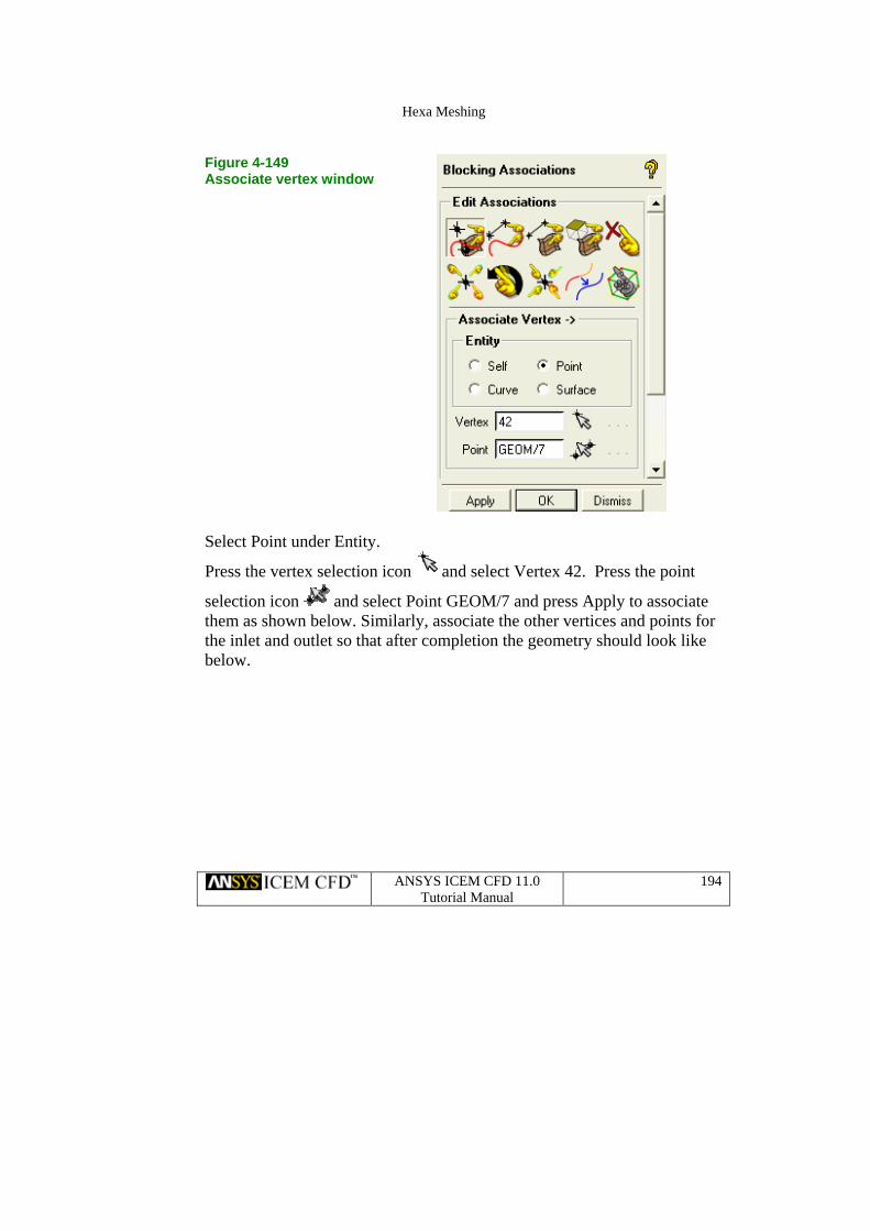
e which is along z-direction. After selecting the edge it will lect the Prescribe point, GEOM/9 and
ress middle click to accept the selection. Similarly, make another split using the same edge but through the Prescribed Point, GEOM/8. Similarly, make another horizontal split through the prescribed point GEOM/12. The final result will have three horizontal splits as shown in below.
Note: Make sure that the Edge that is selected lies within the range of the Prescribed Point that will be selected.
Figure 4-156 Split block window
one of the edgprompt you to select the point Sep

Hexa Meshing
ANSYS ICEM CFD 11.0 Tutorial Manual
201
ontal splits in e block
Figure 4-157 Make the horizth
These are the splits in the ‘k’-direction. The next set of splits will be in the ‘i’ d irection.
ow select the Split method as Screen select. Press the edge selection N
icon
xx
and select any of the horizontal edges (which is along x-

Hexa Meshing
ANSYS ICEM CFD 11.0 Tutorial Manual
202
direction) to create a vertical split. If Settings>Selection>Auto pick mode en to lit
ne ft
while dragging the split to here you want it. Press the middle mouse button to complete the split
n. Then use the same method to create another vertical split on side of the blade.
is OFF, press Apply, and it will ask for alocation on the scre spthrough. Select on a curve or edge on any location that is vertically in liwith the right side of the blade. If Auto pick mode is ON, you should lemouse click on the edge and hold the buttonwoperatiothe left

Hexa Meshing
ANSYS ICEM CFD 11.0 Tutorial Manual
203
on blade sides Figure 4-158 Horizontal splits

Hexa Meshing
ANSYS ICEM CFD 11.0 Tutorial Manual
204
e a block Split is performed, the Index control is updated. After f the K index will be from 0-6.
m) Collapsing Blocks to Display the Blade
In this section, the Collapse feature is introduced to create degenerate blocks for the blade. For clarity in these operations, right mouse click in the Display tree on Blocking>Index Control. Change the Index control for the ‘I’ dimension so that the Min is 2 and the Max is 3. Turn OFF the Points from the Display window. The restricted topology consists of four blocks, where the two center blocks belong to the blade. Before collapsing the blocks, change the Part family of the two center blocks to SOLID, the material representing the blade. Right mouse click on SOLID>Add to part underneath Parts in the Display Tree, and it will open the Add to Part window. Select Blocking Material,
Add Blocks to Part
Note: Every timthe splits are complete, the new range o
xx
, and select the blocks of the blade as shown elow, then press the middle mouse button to complete the operation.
locks
b Figure4-159 Assigningthe blade b

Hexa Meshing
ANSYS ICEM CFD 11.0 Tutorial Manual
205
Merge Vertices
x
> Collapse Block
x
. Now select Blocking >Ce
hoose the edge that should be collapsed. In this case it is the shortest dge of the selected blocks. Select the two blocks shown in the figure
below. Press Apply to Collapse the blocks. Figure4-160 Collapsingthe blade Blocks
After collapsing we get the model as shown below.

Hexa Meshing
Figure 4-161 The CollapsedBlocking
n) Edge to Curve Association on the Blade
Choose Blocking> Associate
x
>Associate Edge to Curve
x
.The Associate edge to curve window will open as shown below.
Note: Make sure Project Vertices is disabled.
ANSYS ICEM CFD 11.0 Tutorial Manual
206

Hexa Meshing
ANSYS ICEM CFD 11.0 Tutorial Manual
207
-162 iation Edge to Curve Window
Figure 4Assoc
You should associate the Edges and corresponding blade curves as shown below.Do this to the top and bottom of the blade, on both sides.
from After associating, Switch on Blocking > Edge > Show Associationthe Display Tree. The geometry should look as shown.

Hexa Meshing
ANSYS ICEM CFD 11.0 Tutorial Manual
208
Figure 4-163
a
Blade edges to be associ tion to curves
Hexa Meshing
ANSYS ICEM CFD 11.0 Tutorial Manual
209
-164 edges
to curves
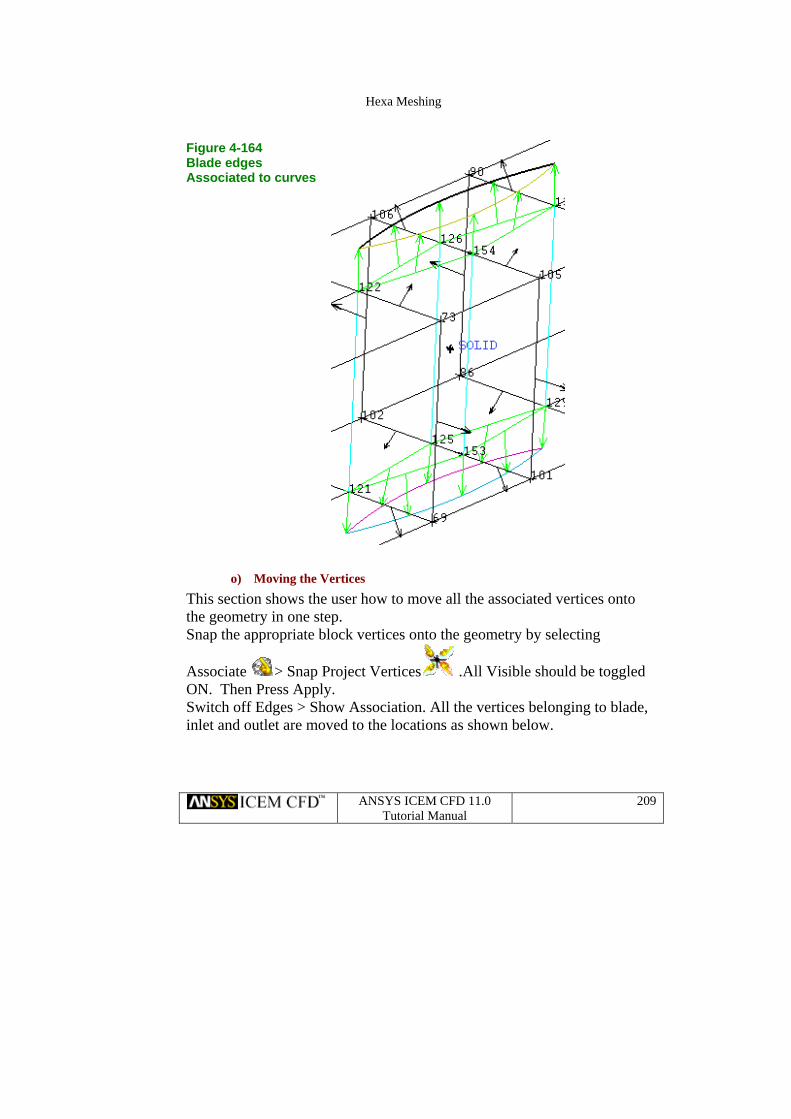
Figure 4BladeAssociated
o) Moving the Vertices
This section shows the user how to move all the associated vertices onto the geometry in one step. Snap the appropriate block vertices onto the geometry by selecting
Associate
x
> Snap Project Vertices
x
.All Visible should be toggled ON. Then Press Apply. Switch off Edges > Show Association. All the vertices belonging to blade, inlet and outlet are moved to the locations as shown below.

Hexa Meshing
ANSYS ICEM CFD 11.0 Tutorial Manual
210
he fipositionsof the vertices beforethe O grid
Figure4-165 T nal
p) Vertex Color Distinction
Notice from this lesson and from previous lessons, that the movement of the vertices is restricted to the associated Curve. The colors of the vertices indicate their associations and degrees of freedom. Vertices associated with Prescribed Points are red and are fixed at a point. Vertices associated to a curve are green and can be moved on the associated curve.
y default, all the vertices lying on the block material boundary are white
e
q) Generating the O-Grid
If the pre-mesh is generated at this point, the existing blocking would result in skewed cells on the four ’corners’ of the pipe. Converting the existing H-Grid type topology to an O-grid type topology inside the pipe will produce a mesh that is low in skewness, with orthogonal grid on the pipe walls. The following steps will improve the overall mesh quality.
Band are free to move on any surface. Additionally, internal surfaces are blue and can be moved along the blublock edges to which they are connected.

Hexa Meshing
ANSYS ICEM CFD 11.0 Tutorial Manual
211
locking >Split Block
x
> O grid Block
xx
Press B
Press
xx
and select all the Blocks of both the FLUID and SOLID gions since the O-grid will be added in the entire pipe as shown in
below. Press the middle mouse button to accept.
Similarly, press
re
xxxxxx
and select the two INLET faces and two OUTLET faces as shown. Press the middle mouse button to accept, and Press Apply to create the O-grid.
igureF4-166Add the faces of the outlet and inlet to O-grid
After creating the O-Grid, the blocking will appear as shown.

Hexa Meshing
Figure4-167 The O-grid
r) Defining Surface Parameters for the Mesh
In this step, the user will define node distributions on the blocking using surface parameters. Surfaces should be turned ON in the Display Tree so they can be selected from the screen.
Select Mesh > Surface Mesh Setup
x
and select the surface selection
icon . Then select all the surfaces by box selecting the entire model or pressing “a.” Enter the Maximum Element size as 0.3, Height as 0.03 and Ratio as 1.25, as shown.
ANSYS ICEM CFD 11.0 Tutorial Manual
212

Hexa Meshing
ANSYS ICEM CFD 11.0 Tutorial Manual
213
igure 4-168 size window
F
Surface mesh
Press Apply to assign the surface parameters. Display the surface parameters by right mouse clicking in the Display Tree on Geometry> Surface > Hexa Sizes. The surfaces will show hexa icons as shown.

Hexa Meshing
Figure4-169 Thesurface parameters
Switch OFF Surface > Hexa Sizes.
s) Defining Edge Parameters to Adjust the Mesh
Although it may be enough to define the meshing with surface parameters, the mesh quality of more complex models can be improved by defining additional edge parameters. Perform these next steps to redistribute points along the diagonal (radial) edge of the O-grid. For the convenience of selecting the edges, right mouse click in the Display Tree to turn ON Vertices > Numbers and Edges > Bunching. Then make sure Vertices in ON. Zoom-in on the OUTLET area of the locking. b
ANSYS ICEM CFD 11.0 Tutorial Manual
214
Select Blocking >Pre-mesh Params >Update Sizes
xx
.Make sure Update All is toggled on (default), and Press Apply. This will compute the
face parameters.
ree ation. The mesh will
node distributions on the blocking edges from the surTurn ‘ON’ Blocking > Pre-Mesh from the Display Tree. Press Yes, when it says, Mesh is currently out of date – recompute? Right click on Blocking > Pre-Mesh > Solid and Wire in the Display Tto display the mesh in Solid/Wire for better Visualizlook like as shown below when viewing the OUTLET.

Hexa Meshing
ANSYS ICEM CFD 11.0 Tutorial Manual
215
-170 efore
mesh eters
Figure 4Mesh bchangingparam
eters, which was 0.03.
esh Params
The mesh is denser at the walls. The near wall elements will have the same initial height that was set on the surface paramIt may be desirable to have denser near-wall spacing.
xxxx
>Edge Params
xx
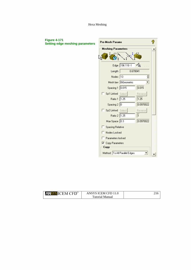
. Turn OFF Select Blocking >Pre-mBlocking > Pre-Mesh so the edges can be easily seen and selected. Select any of the “radial” edges. These are the edges created by the O-grid that are oriented radially in relation to the grid lines that run circumferentially around the tube. Or you can select the same edge shown in the figure below, which is the blocking Edge 196-118. Set Spacing1 to 0.015, which is half the previous value. Set Spacing2 to 0, which will allow it to go as large as possible. Increase the number of nodes to 13 so the Ratio1 (1.25) can be met. Enable ‘Copy Parameters’ and select Method ‘Copy to Parallel edges’ to duplicate these settings on parallel edges in the blocking. Then press Apply.
Hexa Meshing
ANSYS ICEM CFD 11.0 Tutorial Manual
216
rameters
Figure 4-171 Setting edge meshing pa
Hexa Meshing
ANSYS ICEM CFD 11.0 Tutorial Manual
217
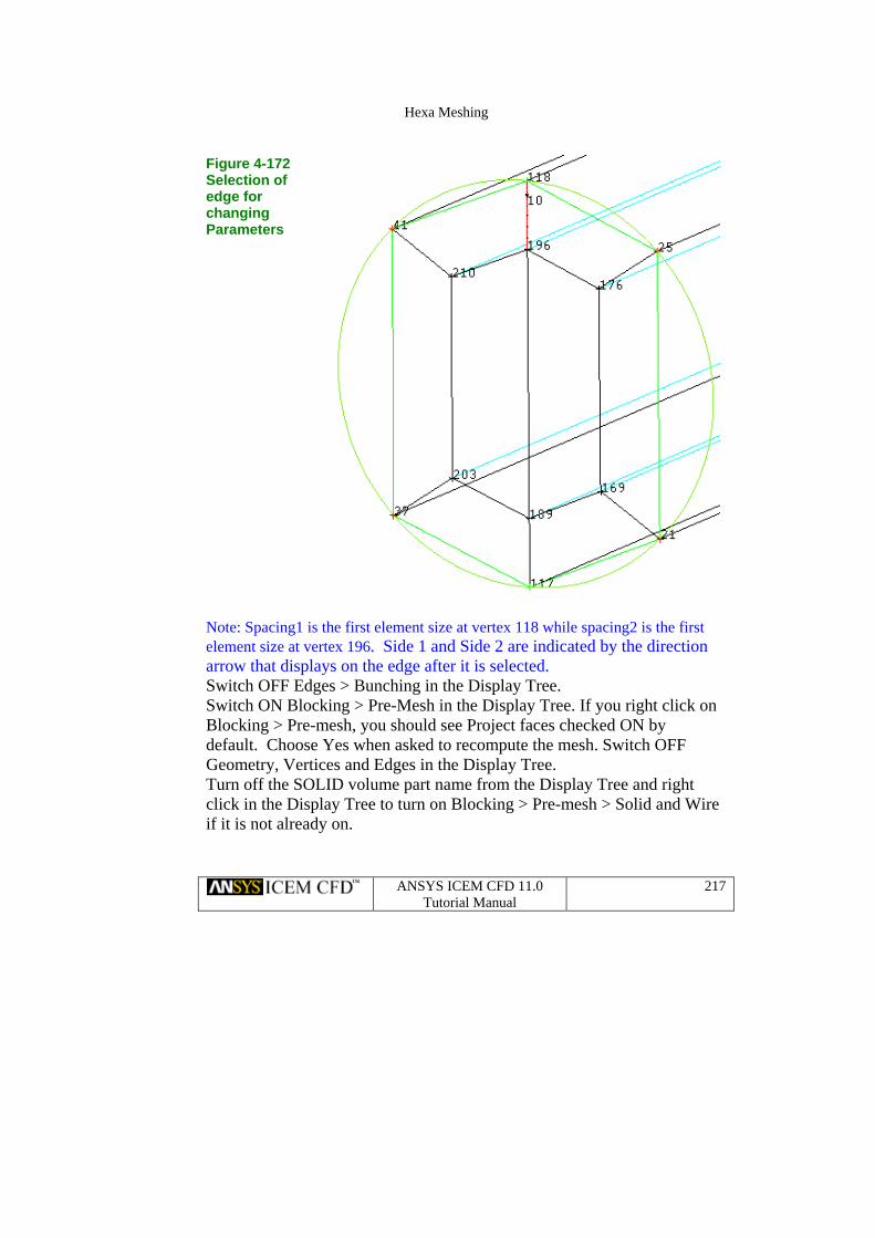
FiguSeleedgchaParameters
re 4-172 ction of e for nging
Note: Spacing1 is the first element size at vertex 118 while spacing2 is the first element size at vertex 196. Side 1 and Side 2 are indicated by the direction arrow that displays on the edge after it is selected. Switch OFF Edges > Bunching in the Display Tree. Switch ON Blocking > Pre-Mesh in the Display Tree. If you right click on
locking > Pre-mesh, you should see Project faces checked ON by
re
Bdefault. Choose Yes when asked to recompute the mesh. Switch OFF Geometry, Vertices and Edges in the Display Tree. Turn off the SOLID volume part name from the Display Tree and right click in the Display Tree to turn on Blocking > Pre-mesh > Solid and Wiif it is not already on.
Hexa Meshing
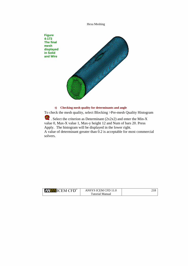
Figure
4-173 The final meshdisplayed in Solid and Wire
t) Checking mesh quality for determinants and angle
To check the mesh quality, select Blocking >Pre-mesh Quality Histogram
. Select the criterion as Determinant (2x2x2) and enter the Min-X value 0, Max-X value 1, Max-y height 12 and Num of bars 20. Press Apply. The histogram will be displayed in the lower right. A value of determinant greater than 0.2 is acceptable for most commercial solvers.
ANSYS ICEM CFD 11.0 Tutorial Manual
218

Hexa Meshing
ANSYS ICEM CFD 11.0 Tutorial Manual
219
hile selecting t 2x2x2
Figure 4-174 Pre-mesh qualitywindow wDeterminan
Figure 4-175 Histogram showing Determinant 2x2x2
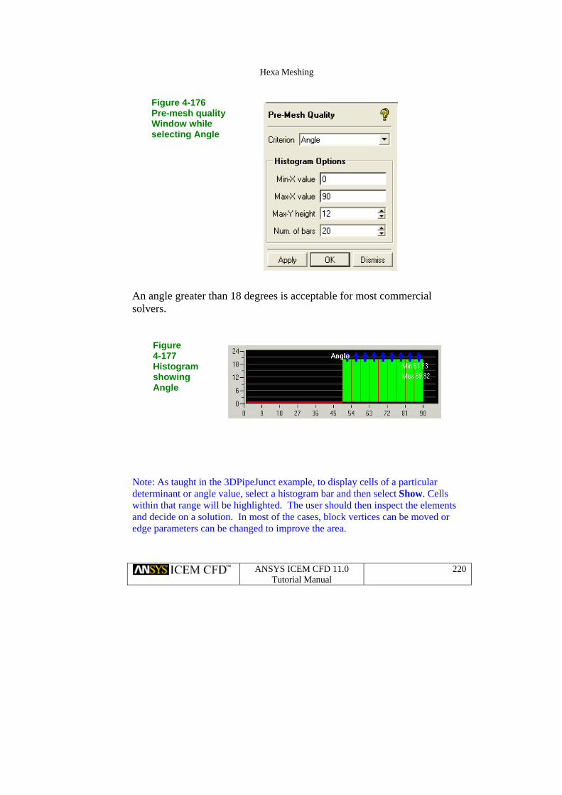
Then, in the Pre-Mesh Quality window at the upper left, select Angle from the Criterion pull down. Enter the values as shown below and press Apply. A new histogram will appear for the internal angles of elements as shown.
Hexa Meshing
ANSYS ICEM CFD 11.0 Tutorial Manual
220
is acceptable for most commercial
f a particular
ld then inspect the elements can be moved or
edge parameters can be changed to improve the area.
Figure 4-176
g Angle
Pre-mesh quality Window while selectin
An angle greater than 18 degreessolvers.
Figure4-177
stogram Hishowing Angle
Note: As taught in the 3DPipeJunct example, to display cells odeterminant or angle value, select a histogram bar and then select Show. Cells within that range will be highlighted. The user shouand decide on a solution. In most of the cases, block vertices

Hexa Meshing
ANSYS ICEM CFD 11.0 Tutorial Manual
221
sh smoother u) Running Pre-me
Before converting the Pre-mesh to an unstructured or structured mesh, the user may choose first to smooth the mesh.
Select Blocking > Pre-mesh Smooth . The Pre-mesh smooth window will then appear. Select the Method as Quality. Select the Criterion as Angle and enter Smoothing iterations 3 and Up to quality 0.5 as shown. Figure 4-178 Pre-mesh smooth window
Press Apply to smooth mesh. Changes in the minimum angle of the mesh can be seen in the histogram as shown. The node position changes made by the pre-mesh smoother will not be saved to the blocking. So reloading the blocking and computing the mesh will always produced the mesh before smoothing. So at this point, you should not recompute the mesh.

Hexa Meshing
Figure 4-179 Histogram after runningsmoother
v) Saving
Select File > Blocking > Save blocking As and enter a name, such as b1.blk. Saving the blocking will allow the user to change any meshing parameters in the future by reloading the blocking onto the geometry. To write the mesh in an unstructured format, right mouse click in the Display Tree on Blocking > Pre-mesh > Convert to Unstruct Mesh. This will write the default name “hex.uns” to the working directory, and
mediately load the mesh. To save the mesh to a different nam, the user an then select File>Mesh>Save Mesh As.
a structured format, right mouse click in the Display Tree on Blocking > Pre-mesh > Convert to MultiBlock Mesh.
imc
e
To write the mesh in
Finally, save the project.
ANSYS ICEM CFD 11.0 Tutorial Manual
222