Embed Size (px)
Citation preview

A STUDY TO DETERMINE A N EFFICIENT DATA FORMAT A N D DATA SYSTEM FOR A LIGHTWEIGHT
DEEP SPACE PROBE
SUMMARY FINAL REPORT
06488- 6020- TOO0 3 1 October 1966
Prepared for NASA Ames Research Center
IVIUI IGI I I ICIU, L U I I I V ~ I I I ~
Under Contract NAS2-3254 L A r r .. r. I I - I . P -
TRW SYSTEMS One Space Park Redondo Beach, California
https://ntrs.nasa.gov/search.jsp?R=19670016530 2019-03-25T01:29:36+00:00Z

Prepared L. M. Bello
Pro jec t Engineer
Manager Data Systems E le c t r onic s D ep a rt men t
.. -11 -

.
C 0 N TE N TS
1. INTRODUCTION.. . . . . . . . . . . . . . . . . . . . 2. SYSTEM DESCRIPTION . . . . . . . . . . . . . . . . .
2 . 1 GENERAL REQUIREMENTS . . . . . . . . . . 2.2 CDS OPERATION . . . . . . . . . . . . . . . . 2.3 INPUT DATA SAMPLING . . . . . . . . . . . . 2 . 4 DATA PROCESSING AND
FORMATTING.. . . . . . . . . . . . . . . . . 2.5 WEIGHT AND POWER SUMMARY . . . . . . . 2 . 6 CDS RELIABILITY ASSESSMENT . . . . . . .
3. CDS EVALUATION AND COMPARISON TO PIONEER V I . . . . . . . . . . . . . . . . . . . . . 3.1 INTRODUCTION . . . . . . . . . . . . . . . . . 3.2 PIONEER VI DATA HANDLING
3.3 TABLE COMPARISON OF CDS AND
SUBSYSTEM DESCRIPTION . . . . . . . . . . PIONEER VI DATA HANDLING SUBSYSTEM . . . . . . . . . . . . . . . . . . .
4. RECOMMENDATIONS AND CONCLUSIONS . . . . . .
Page
1-1
2-1
2-1
2-3
2-6
2-8
2 -9 2 -9
3-1
3-1
3-1
3-3
4- 1
ILLUSTRATIONS
Figure
2-1 Simplified CDS Block Diagram . . . . . . . . . . . 2 -4
2-3 Spacecraft Sector Detail Diagram . . . . . . . . . . 2-7
2-2 CDS Modes of Operation . . . . . . . . . . . . . . . 2-6
2-4 Flow Diagram of Processing and Formatting Operation . . . . . . . . . . . . . . . . 2-10
2-5 Typical Format (1088-Bit Format S i z e ) . . . . . . . 2-11
3-1 Pioneer VI Data Handling Subsystem Block Diagram . . . . . . . . . . . . . . . . . . . . 3 -2

1 . INTRODUCTION
This report summarizes the results.obtained f rom a "Study to
Determine an Efficient Data Forma t and Data System for a Lightweight
Deep Space Probe".
contract NAS2-3254 during the period f rom October 1965 to October 1966. This study has resulted in the definition and overall design of a Central
Data System (CDS) for a spin stabilized deep space probe.
This study was conducted for NASA/ARC under
The CDS consists of an input data. sampler and a central processor .
Digital and analog data i s received by the CDS f rom the experiments and
from the spacecraft performance sensors . This data is sampled by the
input data sampler and processed by the central p rocessor into a highly
efficient format for storage o r transmission.
grammable and under the control of a stored program.
discrete commands and processor p'rogram instructions f rom ground
transmissions.
iments chosen for the study by mutual discussion and agreement with
NASA/ARC. These a re :
Data processing is pro-
The CDS processes
The CDS design is based on a group of eight solar exper-
Micrometeoroid (NASA /GSF C) vi,,- r.=tn ~ ~ ~ ~ ~ t ~ ~ ~ t ~ - I T D D a r \
Cosmic Ray Detector (University of Chicago)
Plasma Probe (NASA/ARC)
Radio Propagation (Stanford)
Fast Neutron Detector (TRW)
Very Low Frequency (TRW)
Cosmic Ray Detector (University of Minnesota).
0 - - - - - - - - - - - - \ - - - . . I . __.
Each of these experiments was studied in detail to determine their inter-
face requirements in t e rms of the number of inputs to be sampled by the
CDS, input signal characterist ics, required data processing, timing
requirements, and sensor control signals.
A number of solar orbital missions, ranging from 0.2 to 1. 8
I
.I. -,*
astronomical units (AU) were studied and their t ra jector ies plotted to
.II .a.
Research Report NO. 2, dated 29 August 1966.
1-1

determine the communications link requirements.
bit ra tes were established to provide adequate communication coverage.
The rates a re :
Eight t ransmission
1) 2048 b p s
2) 1024 bps
3) 512 bps
4) 256 bps
5) 128 bps
6) 6 4 bps
7) 32 bps
8) 16 bps.
The CDS design is based upon the resul ts of the studies which
defined the experiment characterist ics and communication link require-
ments.
overall character ist ic s :
The resultant CDS design provides a system with the following
1) Universal design for many missions.
2) One time development and qualification cost.
3) Capability to process a variable number of experiment
inpurs (rime-snares common data processing circuits).
4) Capability to process sampled data (compress data to reduce
bits required t o t ransmit information - approximating a
data reduction of 10 to 1 ) .
5 ) Ability to provide continuous data sampling during non-
communication periods by the u s e of a bulk s tore unit.
6) Compatibility with the JPL deep space net (DSN).
A simulation philosophy has been established during the course
of this study.
the logic design of the CDS and evaluation of the CDS performance.
has been concluded that a simulation is desirable during the design phase
of the CDS.
This simulation philosophy has been developed to aid in
It
1-2
2. SYSTEM DESCRIPTION
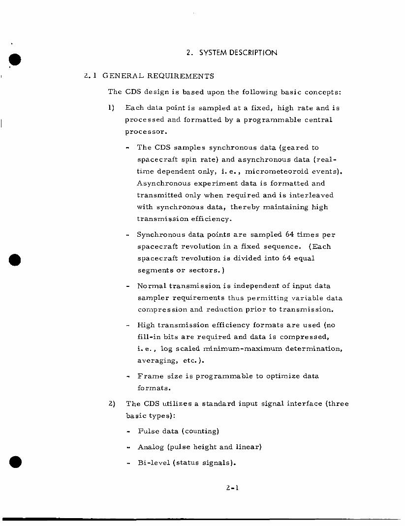
2.1 GENERAL REQUIREMENTS
The CDS design is based upon the following basic concepts:
Each data point is sampled at a fixed, high rate and i s
processed and formatted by a programmable central
processor.
- The CDS samples synchronous data (geared to
spacecraft spin rate) and asynchronous data ( rea l -
time dependent only, i. e., micrometeoroid events).
Asynchronous experiment data is formatted and
transmitted only when required and i s interleaved
with synchronous data, thereby maintaining high
t r an sm i s si on efficiency . - Synchronous da ta points a r e sampled 64 t imes per
spacecraft revolution in a fixed sequence.
spacecraft revolution is divided into 64 equal
segments o r sectors. )
(Each
- Normal t ransmission i s independent of input data
sampler requirements thus permitting variable data
corilpres sion and reduction pr ior to transmission.
- High t ransmission efficiency formats a r e used (no
fill-in bits a r e required and data is compressed,
i. e. , log scaled minimum-maximum determination,
averaging, etc. ).
- F r a m e size i s programmable to optimize data
formats.
The CDS uti l izes a standard input signal interface ( three
basic types):
- Pulse data (counting)
- - Bi-level (status signals).
Analog (pulse height and l inear)
2-1

3 ) The input data sampler is expandable up to 64 data
points in a given sector.
4) The CDS has five programmable modes of operation:
- Transmission of realt ime data interleaved with
stored data
- Transmission of realt ime data only
- Transmission of high rate engineering data only
- Self tes t mode
- Data store mode.
5) The CDS has three fixed modes of operation:
- Processor program verification (contents of
program memory a r e transmitted to ground)
- Fixed realtime t ransmission (limited capability)
synchronized by either actual o r simulated sun
pulse
- Stored data transmission only.
/ \ m-8 --- V I A l l = L ~ u ~ L u r e G a ~ d during perioas 01 noncommuni-
cation for la te r transmission.
- Thirteen hours of stored data a r e compressed and
transmitted (interleaved) with 11 hours of compressed
realt ime data.
sampling during any 24-hour period.
This i s to provide continuous data
7) A command system is provided for uplink t ransmission
of discrete commands and processor program instructions.
A l l transmitted commands are self-verified pr ior to
execution. >:
8) Convolutional coding is used to improve t ransmission
capability .
.r; 'L'
Convolutional coding scheme developed by Dr. Dale R. Lumb, NASA/ARC.
2-2

9) Design and operational flexibility:
- Provide system flexibility from mission to mission
by utilizing standard experiment interfaces and
p rog ram m able ope ration
- Provide the capability for in-flight program modifi-
cation to optimize system operation to unexpected
conditions.
2 .2 CDS OPERATION
The basic GDS design consists of the following elements:
Input data sampler (IDS)
Input data buffer (IDB)
P rocesso r
Output buffer (OB)
Bulk s tore unit
Fixed realt ime t ransmission logic Convolutional coding logic
Command processor.
r r i m-- - 1 . -. - . -- /& ~~~~~~l~~~~~ L l G d . & & & A U L L J U A LLLG UYU ACJ C J l l U W l l A l l A ' A g U L C &-A. L i l t :
solid l ines in the figure i l lustrate data flow; the dotted l ines i l lustrate
control signals.
The CDS samples input data from experiment packages and from
spacecraft performance sensors i n the form of th ree bas ic types of signals
(analog, pulse, and bi-level data).
accuracy by one t ime shared analog-to-digital converter.
All analog data is encoded to 8-bit
Each synchronous data source, dependent upon spacecraft rotation,
i s sampled 64 t imes per spacecraft revolution and stored for processing
by the central processor.
the IDB, performs the required data compression (i. e., log scaling,
minimum-maximum determination, averaging, etc. ), and formats the
processed data for transmission.
by a stored program.
permit efficient utilization of the selected data bit rates.
The processor selects the desired samples from
All processor operations a r e controlled
The size of the output format i s programmable to
2 - 3

DATA INPUTS BASED ON RESEARCH REPORT NO. 2
DATA BUFFER
4 I 1
- - _ . _
h
/ANALOG PULSE BI-LEVEL ’ DATA DATA DATA FAST
FIXED REALTIME TRANSMISSION
- - _
LOGIC GROUND .
NEUTRON 3 DATA
i
AUXILIARY MEMORY
PROCESSOR
D I G I TA L
INPUT DATA SAMPLE s +l INPUT
I COMMAND PROCESSOR I
1 I I I
“p-- 1 BULK STORE
-- +CONTROL
___) DATA
C O D I N G LOGIC
TO TRANSMITTER
Figure 2-1. Simplified CDS Block Diagram
2 -4

The CDS timing and synchronization has been designed to provide an input data sampler whose operation is essentially independent of t r an ,. mission link requirements. That is, experiment data is sampled by the
IDS and stored within the IDB until the processor is ready to select data
for processing. The processed data i s formatted and placed into one of
the two output buffers for transmission.
that data must be processed at a high enough ra te to insure that sufficient
data will be available f o r continuous uninterrupted transmission.
The only timing requirement i s
This independence of data sampling to t ransmission link require-
ments permits variable data processing to be performed pr ior to
transmission. F o r example, as the allowable t ransmission bit ra te
decreases due to the earth-spacecraft distance, the processor wi l l se lect
fewer samples to be transmitted per spacecraft revolution.
compression also wi l l be performed on data that i s transmitted, thus
minimizing information transmitted with the available t ransmission bit
rate.
More data
The CDS has five programmable modes of operation (Figure 2-2).
Only one mode of operation is permissible at any given time.
realtime i n t e r l e a v e d with s t o r e d data refers t n t h e npPrAtinn i n urhirh
the spacecraft is i n communication with the DSIF stations.
expected for a duration of approximately 11 hours a day.
time, the CDS wi l l alternately t ransmit one f r ame of realt ime data and
one f r ame of stored data from the bulk s tore unit.
only mode t ransmi ts only realtime data (no bulk s tore data).
provides twice the realt ime data ra te as the realt ime/bulk s tore mode.
The data s tore mode re fers to storing data into the bulk s tore; this mode
i s expected to be required approximately 1 3 hours a day.
engineering only re fers to the t ransmission of spacecraft performance
and experiment status data a t a high rate during launch phases o r during
t imes of suspected spacecraft malfunction. A self tes t mode is provided
to evaluate CDS performance during the course of the mission.
The
This is
During this
The realt ime data
This mode
High ra te
Each programmable mode requires an individual program; however,
common subroutines a r e shared among all programs. That is, the
processor program memory is organized with one section o r bank con-
taining subroutines and the other bank containing the main programs.
Whenever a main program requires a subroutine, the main program
2-5

CDS Mor PROGRAM CONTROLLED OPERATION
FIXED PROGRAM OPERATION
TRANSMISSION TRANSMISSION DATA STORAGE TRANSMlSSlON SELF TEST PROGRAM STORED DATA REALTIME OF REALTIME OF REALTIME OPERATION OF HIGH RATE VERIFICATION TRANSMISSION FORMAT
WITH STORED DATA ONLY DATA INTERLEAVED DATA ONLY (BULK STORAGE) ENGINEERING ONLY
DATA
Figure 2-2. CDS Modes of Operation
branches off into the subroutine.
is made back to the main program.
After performing the subroutine a jump
The three fixed operational modes a r e designed to bypass the
processor .
engineering data during periods when the processor program is being
They a r e used to t ransmit a limited quantity of scientific and
modified and d i l r i n u timr-.c: x x 7 h p n a nvneaacnr rn-lF----f:n- :- - - - - - - - A - -' _.___--______--- -" yurr ru . - The input data sampler operates in its normal sequence during this mode
of operation. However, instead of the processor selecting data samples
f rom the IDB, samples a r e selected f rom the IDB by a fixed programmer.
The selected data is direct ly formatted by the use of a combiner and is
fed to either the convolutional coding circui t ry o r to a simple parity
generator. The output from the CDS modulates the te lemetry t ransmit ter .
2 . 3 INPUT DATA SAMPLING
The basic requirements of the IDS a r e to:
Sample analog, biphase, and pulse data
Analog -to -digital encode analog inputs
Store sampled data into the IDB for later processing by
the processor.
A fixed programmer provides the signals required to sample all inputs i n
a fixed sequence. Bi-level data i s sampled and stored directly into the
2 -6

IDB.
IDB.
entry into the IDB.
Pulse data i s accumulated within counters and then stored within the Analog data is sampled and encoded into an 8-bit binary number for
As stated ear l ie r , a l l high rate data is sampled 64 t imes pe r space-
craf t revolution.
revolution into 64 equal segments called sectors.
divided into 64 segments called words.
This is accomplished by dividing each spacecraft
Each sector is a l so
Figure 2 - 3 i l lust rates the characterist ics of a single spacecraft
sector. As shown, analog inputs a r e sampled, encoded, and stored within
the IDB during word t imes 1 through 20.
sector and stored within the IDB during word t imes 2 1 through 34.
ra te data i s sampled once per spacecraft revolution in word 35. commutated data is sampled once per 64 spacecraft revolutions in word 36.
Pulse data is sampled for one
Low
Sub-
' 0 r SECTOR WORD
START
(SAMPLED RATE ONCE PER
K C V U L U I I U NJ
ENGR DATA ghTFLpEE"R (SUBCoMM) 64 REV0 LUTlO N)
I ) STORE CONTENTS OF PULSE
WITHIN IDB I ) SAMPLE ANALOG COUNTERS
1) SPARE WORDS INPUTS
\ 2) ENCODE ANALOG DATA
3) STORE RESULTS IN INPUT DATA BUFFER (IDB) \
FOR CHANGES I N SPIN RATE
ONE SPACECRAFT
15.6 MSEC (1 RPS)
5.6 DEGREES
Figure 2 - 3 . Spacecraft Sector Detail Diagram
2-7

2.4 DATA PROCESSING AND FORMATTING
Data processing is defined as those operations performed on samplc
data by the processor pr ior to transmission.
include :
Processing operations
Selection of specific data from the IDB and the
auxiliary memory
Data processing
0 Data formatting.
These operations a r e programmable and a r e under the control of a
processor instruction memory.
The processor is capable of performing specific data compression
such as log scaling, averaging, determining minimum and maximum
values of n samples, and any other data operation which can be performed
by basic addition, subtraction, and shifting left and right. At lower bit
rates, the processor will reduce the number of bits per f r ame by selecting
fewer samples per spacecraft revolution and by performing more data
compression such as log scaling data, finding minimum-maximum values,
~ L C .
t ransfer of data from the processor to the output buffers.
t ransfer operation the processor will perform the following formatting
steps:
FurrriaLLing u I prvcessea aaza is automatically per lormed in the
During the
1) Select the f r ame synchronization bits from the processor
instruction memory and en ter them into the appropriate
output buffer memory locations.
2) Enter subcommutator, bit rate, and format identification
into appropriate output buffer locations.
3 ) Store processed data into programmed output buffer loca-
tions. Store sector identification bits to identify data with
its sector sampling address where required, i. e. ,
minimum-maximum.
2 -8

4) D c t e r i n i n e the size of each f r ame according to the
pro ce s sor program.
5) Format and s tore each f r a m e of data to permit
continual uninterrupted real t ime t ransmission of data
alternately f rom the two output buffers.
A typical processor program flow diagram is shown in F igure 2-4.
A typical format for 1024-bps t ransmission bit ra te is shown in
Figure 2-5.
which a r e possible by programming.
basic sections:
This is one example of any number of possible formats
The format is divided into four
F r a m e identification
High rate data
Low rate data
0 Subcommutated data.
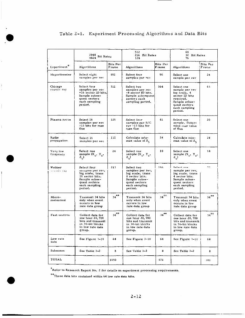
Table 2 -1 lists the processing algorithms and total t ransmission bits for
each experiment for the eight t ransmission bit rates.
can be derived from Table 2-1.
CDS modes of operation shown in Figure 2-3.
Various formats
A format ID identifies all formats for the
2.5 WEIGHT AND POWER SUMMARY
The weight and power assessment for the CDS i s based upon the use
of low power integrated circuit logic such as the Fairchild 9000 ser ies .
The Fairchild 9000 s e r i e s integrated circui ts were selected due to their
low power consumption and their off-the-shelf availability.
Table 2-2 summarizes the weight and power requirements for the
CDS.
2.6 CDS RELIABILITY ASSESSMENT
The CDS reliability is calculated based upon component failure ra tes
suggested by NASA/ARC.
suggested for use in calculating CDS reliability to allow a comparative
analysis between the CDS and the Pioneer VI system reliability using the
same ground rules.
Pioneer VI component failure ra tes were
2 -9

START
PUT FORMAT ID INTO OUTPUT
PUT FRAME SYNC ID INTO OUTPUT BUFFER .LOG SCALE PROCESSING
ADD SECTOR I O I F REQUIRED
+l+
FETCH SUBCOMM ID FROM INPUT BUFFER
PUT SUBCOMM I D INTO OUTPUT BUFFER
I DETERMI NE LENGTH OF:
-7-- DATA INTO THE
TEST FOR END OF FRAME
AWAIT MARKER SIGNAL FROM OUTPUT BUFFER
Figure 2-4. Flow Diagram of Processing and Formatting Operation
2-10

r -----------
$ 1 e: : . I
I I I I
S I c
5
L n Y N ' - m
m .Z m
T .< m
>. 2
Y
m c 0 m - Y
iii d
Y id
c
cc QJ N m .A
44 Id E k 0 Frr
4 Id u a h b
.r(
m I
N
Q)
M 2
.A
Frr
2-11
Magnetometer Select eight 192 samples per rev
Y Select four 312 samples per rev t 1 6 sector ID bits. Sample subse- quent sec tors
Select four samples per S I C r e v t 1 3 bi ts for max flux
41
I I
Subcomm See Table 3-2 8
TOTAL 1050
Table 2-1. Experiment Processing Algorithms and Data Bits
512 256 Bit Rates
64 32 Bit Rates 76 128
Bits P e r I Experiment* 1 Algorithms F r a m e Bi t s P e r
Algori thms F r a m e Bits P e r
Algorithms F r a m e
I 24 I Select one sample per r e v
Select four samples per rev
I Select one sample per rev log scale, 4 sec tor ID bi ts required, Sample subse- quent sec tors each sampling period.
Chicago cosmic ra
164 Select two samples per r e v t 8 sec tor ID bits. Sample subsequent s e c t o r s each sampling period.
I ~~ ~~
Select one sample. Deter- mine max value of flux
Plasma probe Select 16 samples p e r r e v t 1 3 bi ts for rnax '.- Radio propagation Select samples 16 per s e c Calculate min-
max value of S 5 24 ! Calculate min-
max value of S5
Select one Select one frequency sample (Xc. Yc, I Very low I zc)
Select one sample (Xc. Yc.
C' I I
Webber - - I ____..-_ Select four
r - r u p c r p e r rev. log scale, t r a n s 16 sec tor bits. Sample subse- quent s e c t o r s each sampling period.
213 Select two samples per rev, log scale, t rans 8 sec tor bits. Sample subse- quent s e c t o r s each sampling period.
Salart -..e
sample per rev, log scale, t r a n s 4 sec tor bits. Sample subse- quent sec tors each sampling period.
I I
Micro- meteoroid
34** Transmi t 34 bi ts only when event occurs in low ra te data group
34** Transmi t 34 bi ts only when event occurs in low ra te data group
only when event occurs in low ra te data group I
F a s t neutron Collect da ta for one hour 20,700 bi ts and t ransmi t in 34-bit blocks i n low r a t e data group.
34** Collect da ta for one hour 20,700 bits and t ransmi t i n 34-bit blocks in low ra te data group.
34** 34** Collect da ta for one hour 20,700 b i t s and t ransmi t i n 34-bit blocks i n low r a t e data group.
Low ra te See F igure 3-10 64 I data 64 See F igure 3-10 1 6; 1
See Table 3-2
301
See F igure 3-10
7 See Table 3-2 I I I 1 571
*Refer to Research Report No. 2 for detai ls on experiment processing requirements . **
These data bi ts contained within 64 low rate data bits.
2-12

Table 2-2. CDS Weight and Power Summary
Subsystems
[nput data sampler logic
Processor logic
Command p rocesso r *
Power converter
Memories
1) Two input da ta buffers (12K bits each)
2) Two output buffers (1.2K bits each)
3) One auxiliary memory (30K bits)
4) Two processo r memories (18K bits each)
Total
_____ ~~~ ~
t Peak power = 1 . 7 w.
~~
Power (watts)
2.2
2.2
ow average ,ewer - unit urned off when lot used
- -
0.43
0.16
0.10
0.26 for one 6 . ?c;
:8.9 watts raw lower) **
Weight (pounds)
1.5
1.5
0 .5
3.0
2.5
2.0
2.5
3.0
1 6 . 5
** Total Power In, assuming 60% converter efficiency is: P. = 5.3510.6 8 .9 watts. in
2 - 1 3

CDS reliability is calculated for th ree mission times: 1 year,
1. 5 years , and 2 years.
t ime periods a r e listed below.
data retrieval.
The mission phase reliabilities for these three
These members are based on a n 80 percent
CDS
Pioneer VI
Pioneer v?‘ With Tape Recorder (Bulk Store)
Without Tape Recorder . D T U . (Bulk Store) *DSU -CDU
M i s s i o n Mission Time Mission Time r Time
1 Y e a r 1.5 Years 2 Years 1 Y r Y r s 2 Y r s 0 .5 Y r
0.28 0. 14 0.07 0 . 6 7 0. 54 0.43 -
1.5
- - - 0. 68 - - - i
The reliability numbers listed in the first three columns of the
table reflect the low reliability of the bulk store, magnetic tape unit.
The magnetic tape unit considered for the CDS has the following rel ia-
bilitie s :
1 year mission - 0.411
1.5 year mission - 0.264
2 year mission - 0.169.
A s indicated, the CDS reliability is much greater than the magnetic
tape unit.
bulk s tore unit should be investigated for use within the CDS.
Therefore, either redundant tape units or a more reliable
2-14

3. CDS EVALUATION AND COMPARISON TO PIONEER VI
3.1 INTRODUCTION
A requirement of the study contract is to compare the CDS design
to a baseline system.
chosen as the baseline system by mutual agreement between TRW Systems
and NASA/ARC.
The Pioneer VI data handling subsystem w a s
3.2 PIONEER VI DATA HANDLING SUBSYSTEM DESCRIPTION
The Pioneer V I data handling subsystem i s made up of a digital
te lemetry unit (DTU), a data store unit (DSU), and a command decoder.
A redundant command decoder and a redundant programmer is used within
the DTU in the Pioneer VI system.
Figure 3-1.
individual processing blocks and storage blocks.
A sys tem block diagram i s shown in
The six experiment sensors a r e shown along with their
The DTU processes all inputs into a PCM t ime multiplex format
which biphase modulates a 2048-Hz subcar r ie r .
output of the DTU which modulates the t ransmit ter .
This subcar r ie r is the
The inputs to the DTU consist of dicit21 data frnm the nvner;---+ ---I---- - ----’ ’
~~ ----------r--&..- CALL- I . ~ - C - A G V G L aiiu
analog from the spacecraft performance sensors .
only digital data from the experiment package since all data processing
and A/D conversion is accomplished by the individual experiments (except
f o r the radio propagation).
The DTU receives
Signals from the command decoder select different bit ra tes and
modes of operation via uplink t ransmission from the tracking stations.
The range of the te lemetry t ransmission bit ra tes is from 8 to 512 bps
i n five steps.
four t ransmission formats.
Any one of the five bit ra tes may be commanded for each of
The DTU a lso provides various timing and gating pulses to the
experiments as required.
If more detailed information i s required on the Pioneer V I data
handling system, re fer to NASA/ARC PC documents (PC-046.01).
3-1

COSMIC COSMIC RAY MAGNETOMETER PLASMA RAY (CHICAGO) (GSFC) W I T )
RADIO PLASMA (GRCSW) PROPAGATION (NASA/ARC)
Figure 3-1. Pioneer VI D a t a Handling Subsystem Block Diagram
3 -2

The DSU provides 15, 232 bits of storage during noncommunication
periods with the DSIF stations.
commanded, the output of the DSU is read out by the DTU.
When t ransmission of s tored data is
3.3 T A R L E COMPARISON OF CDS AND P I O N E E R VI DATA HANDLING SUBSYSTEM
Table 3-1 summar izes the character is t ics of the CDS and the
Pioneer VI data handling system.
3-3

Table 3-1. Comparison of CDS and Pioneer VI Data Handling System
Pioneer VI CDS
Number of inputs 15 d ig i ta l s 27 pulse data, 91 analog, processed and 71 analogs 17 bi-levels. Additional t rans mi tted 6 6 bi-levels inputs may be accommodated
1 spin ra te by adding sampler gates and Additions cannot reprogramming the proces - be made without so r instruction memory to redesign due process additional s ignals . to the fixed formats used.
Sampling ra te (assuming 1 r p s samples/experi- spin rate) ment/ second
Max of 2. 3 64 sample s / exp / sec
Number of formats
4 (fixed) P r o g r a m ma ble , t y pi cally 8 programmable, 2 fixed
Forma t s ize 224 bits (fixed) Programmable , typically 2K bits, l K , 0. 5K, and 0.25K bits
Spacecraft word s ize
(fixed) 6 bits t Programmable, word one parity s ize variable (7-bit word size)
~~
Transmission 512 bit rates 2 56
64 16 8
2 048 64 1024 32 51 2 16 128
Modes of operation Realtime
Telemetry s tore
Duty cycle s tore
Memory readout
P rogram controlled:
Transmiss ion of real t ime interleaved with stored data
Transmiss ion of real t ime data only
Data s torage operation during noncommunication periods (bulk storage)
3 -4

Table 3 - 1 (Continued)
Pioneer VI CDS ~ ~~
Transmiss ion of high r a t e engineering data only
Self t es t
Fixed ope rations:
P rogram verification
Realtim e fo rma t
Data storage readout
Ground commands 128 128
Number of 6 (fixed) 8 (more can be added) experiments
Re liability 0.68 for 6 months
0.67 for 1 year 0.54 for 1.5 yea r s 0.43 for 2 y e a r s (excludes bulk s to re tape unit)
Data storage Data handling 56, 000, includes 2 input data (bits) system - buffers, 2 output buffers,
and the auxiliar memory. Y 15,232 Experiments - Bulk s tore =3lO bits. 2292 Total - 17, 524 bits
~ ~- ~
Weight (lbs) Data handling - CDS 16. 5 lbs 10.6 lbs 8 experiments 11. 0 lbs Decoder - 6.0 lbs minus CDS 6 experiments - processing c i r - 34. 7 :bs cuits (does not Total - 51. 3 lbs include bulk s tore) 27. 5 lbs
Power (watts) Data handling - GDS (total) 8.9 w
6 experiments - Total 19.9w 4.4 w 8 experiments 11. Ow
7.3 w Decoder - 1.4 CDU negligible Total - 13. 10
3-5
/
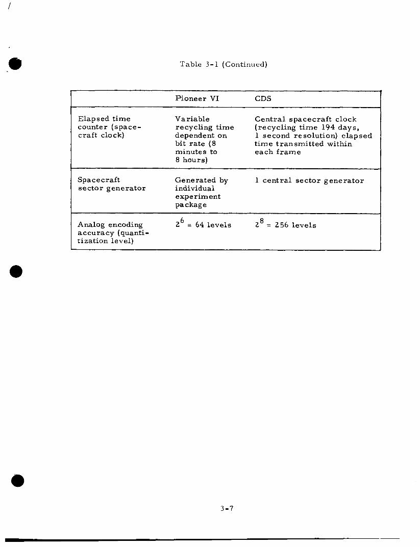
Table 3 - 1 (Continued)
~
T
Pioneer VI CDS
Elapsed t ime Variable Central spacecraft clock counter (space- recycling t ime (recycling t ime 194 days, c raft clo c k) dependent on
bit rate (8 minutes to each f r ame 8 hours)
1 second resolution) elapsed t ime transmitted within
Space craft Generated by 1 central sector generator sector generator i ndivi du a1
experiment package
8 2 = 256 levels 6 Analog encoding 2 = 64 levels accuracy (quanti- tization level)
1 I
3-7

Table 3 - 1 (Continued)
- ~~
Pioneer VI CDS
Ground stations DSIF DSI F
Fai lure modes 1 redundant Fa i lure mode bypass capa- programmer bilities by reprogramming 1 redundant command de coder instruction memory, IDB,
CDS to bypass failed com ponent ( in pro c e s so r
processor , etc. )
Data t ransmission As many a s No fill-in bits required efficiency 40% of bits
transmitted consists of f i l l - in bits - (format A 512 be s)
Data processing Fixed process- Programmable by central ing within each processor: experiment Log scaling
Min-max
Max
Averaging
Number of sec tors Fixed by 64 sec tors for each sampled per space- experiments c raf t r e vo luti o n
Number of A/D 6 within 2 (1 redundant) r e qui red experim ent s
1 inDTU
s yn ch r o nou s ex p e r im en t 16 rnax
~~
7 Bulk storage 15,232 bits 2* 10 bits (tape) (core)
Data sampling De pendent on Constant intervals sequence particular
experiment data p ro c e s s i ng timing (not constant)
3-6
4. RECOMMENDATIONS AND CONCLUSIONS
The resul ts of the study indicate that a CDS i s practical for use in
a lightweight deep space probe i n t e r m s of meeting the requirements for
weight, power, and flexibility. The principle advantages over a fixed
hardwired system a r e :
Because of the favorable resul ts obtained in meeting the goals of
Higher information rate for a given bit ra te
A fixed hardware design is usable for many missions.
the study and the improvements it provides over the Pioneer VI type
system, it is recommended that the CDS design be car r ied out through a
detailed logic and circuit design. Specifically, it i s recommended that
the following a reas be further studied for possible inclusion within
the detailed logic design:
Reduce required average power by use of power gating
techniques.
U s e one central memory system as opposed to separate
memories (i. e., processor instruction memory, auxiliary
memory, input data buffer, and output buffer).
Use CDS memories interchangeably. F o r example, u s e
the auxiliary memory in place of one or both input data
buffers.
Standardize memory sizing i n t e r m s of word length,
modularization packaging, etc.
Extend data reduction capabilities and techniques.
Increase the computational capability of the processor to
perform more extensive data reduction (i. e. statistical
analysis) . Use the processor to perform convolutional coding.
Use a n NDRO processor instruction memory.
4- 1