Embed Size (px)
Citation preview

A STUDY ON THE PERFORMANCE OF LOCAL EXHAUST
VENTILATION SYSTEM USING MAHALANOBIS APPROACH
MUHAMMAD HASBI BIN ABD HALID
UNIVERSITI MALAYSIA PAHANG

i
A STUDY ON THE PERFORMANCE OF LOCAL EXHAUST VENTILATION
SYSTEM USING MAHALANOBIS APPROACH
MUHAMMAD HASBI BIN ABD HALID
THESIS SUBMITTED IN FULFILLMENT OF THE REQUIREMENTS FOR THE
AWARD OF THE DEGREE OF BACHELOR CHEMICAL ENGINEERING AND
NATURAL RESOURCES
FACULTY OF CHEMICAL & NATURAL RESOURCES ENGINEERING
UNIVERSITI MALAYSIA PAHANG
February 2013

vi
A STUDY ON THE PERFORMANCE OF LOCAL EXHAUST
VENTILATION SYSTEM USING MAHALANOBIS APPROACH
ABSTRACT
The title of this experiment is a study on the performance of local exhaust ventilation
system using Mahalanobis approach. The objectives of this study are to obtain
normal pattern operation of local exhaust ventilation (LEV) system and to
characterize the pattern to study the performance of the above system. An experiment
was conducted in determining the average face velocity of the fume hood. This was
done by taking several readings at equidistant points. The average face velocity was
checked on reference guidelines of fume hood to see whether the fume hood is safe
to use or otherwise. Then, with the same data obtained from the experiment, it was
analysed using Mahalanobis Distance approach. Then, the result of both methods
will be compared. After it had been analysed, 5 points of face velocity were obtained
compared to the 16 initial points, thus proving Mahalanobis approach making it a
better and faster way in determining the performance of the fume hood and the LEV
system.
vii
SATU KAJIAN MENGENAI PRESTASI PENGALIHUDARAAN
EKZOSTEMPATAN MENGGUNAKAN PENDEKATAN MAHALANOBIS
ABSTRAK
Sistem ekzos setempat ventilasi seharusnya diperiksa secara berkala untuk memantau
prestasinya. Dalam projek ini, satu kaedah statistik baru yang dipanggil Jarak
Mahalanobis telah digunakan untuk tujuan ini. Tujuan projek ini adalah untuk
mengenal pasti pola operasi normal bagi system pengudaraan ekzos setempat (LEV)
dan mencari corak untuk mempelajari prestasi system di atas. Satu eksperimen telah
dijalankan dalam menentukan purata halaju tukup wasap. Ini telah dilakukan dengan
mengambil beberapa bacaan di setiap jarak yang sama. Purata halaju permukaan
telah dibandingkan dengan panduan rujukan sedia ada untuk melihat sama ada tukup
wasap selamat untuk digunakan atau sebaliknya. Kemudian, dengan data sama yang
diperolehi daripada eksperimen, analisis dilakukan dengan menggunakan pendekatan
MD. Sebagaimana kejayaan teknik MD dalam pengecaman pola, keputusan
menunjukkan bahawa MD dengan skala ketaknormalannya mempunyai satu
keupayaan yang bagus dalam mengiktiraf prestasi LEV. Keputusan yang diperolehi
memuaskan jika dibandingkan dengan kaedah tradisional. Selepas dianalisis, 5 titik
halaju muka diperolehi berbanding dengan 16 titik awal. Oleh itu, ini membuktikan
pendekatan mahalanobis member satu cara yang lebih baik dan lebih cepat dalam
menentukan prestasi tukup wasap dan sistem LEV.
viii
TABLE OF CONTENTS
PAGE
SUPERVISOR’S DECLARATION ii
STUDENT’S DECLARATION iii
ACKNOWLEDGEMENT v
ABSTRACT vi
ABSTRAK vii
LIST OF FIGURE xi
LIST OF TABLES xii
LIST OF ABBREVIATIONS xiii
CHAPTER 1: INTRODUCTION
1.1 Background of Proposed Study
1.2 Problem Statement
1.3 Research Objectives
1.4 Scopes of Study
1.5 Significance of Study
1.6 Expected Outcome
1.7 Concluding Remarks
1
3
5
5
6
6
7
CHAPTER 2: LITERATURE REVIEW
2.1 Ventilation System
2.1.1 Natural Ventilation
2.1.2 Spot Ventilation
2.1.3 Whole-house Ventilation
2.2 Local Exhaust Ventilation System
2.2.1 Fume Hood
2.3 Advantages of LEV
2.4Disadvantages of LEV
2.5 Conventional ways to study performance LEV
8
9
10
10
11
12
13
14
14
ix
2.5.1 Air Velocity Measurement
2.5.2 Tracer Gas Method
2.5.3 Smoke Release Observations
2.6 Mahalanobis Distance
2.6.1 Definition of Mahalanobis
2.6.2 Concept of MD
2.7 Calculation using MD
2.8 Method of MD
2.8.1 Calculation of MD using Mahalanobis Taguchi System
(MTS)
2.8.2 Calculation of MD by the
Mahalanobis Taguchi Gram–Schmidt System (MTGS)
2.9 Advantages using Mahalanobis Approach
2.10 Applications of MD
CHAPTER 3: METHODOLOGY
3.1 Research Design
3.2 Instrument and Equipments
3.3 Data Collection
3.4 Data Analysis
3.4.1 Testing of LEV
3.4.2 Calculation of Volumetric Flow Rate
3.4.3 MD Calculation
CHAPTER 4: RESULT AND DISCUSSION
4.1 Overview of Results
4.2 Traverse Point
4.2.1 Normal Data
4.2.2 Abnormal Data
4.3 MD Data
4.3.1 Normal group
4.3.2 Abnormal Group
4.4 Response Graph of S/N Ratio
4.5 Confirmation o f Result
15
16
16
17
17
17
18
19
20
22
23
24
25
27
28
30
30
31
32
34
35
35
37
40
40
46
56
57
x
CHAPTER 5: CONCLUSION
REFERENCES
APPENDICES
Appendix A MTS calculation for each level of the orthogonal array
Appendix B Response data
58
59
61
68

xi
LIST OF FIGURE
Page
Figure 1.1 Hood performance by Average Face velocity 3
Figure 2.1 Schematic diagram of LEV 12
Figure 2.2 Diagram of a fume hood 13
Figure 3.1 Overall process flow diagram 26
Figure 3.2 Anemometer in laboratory 27
Figure 3.3 Manometer pitot tube 27
Figure 3.4 Sample Point on LEV 28
Figure 4.1 Traverse point in (a) vertical and (b) horizontal axis 36
Figure 4.2 Traverse point in (a) vertical and (b) horizontal axis 36
Figure 4.3 Traverse point in (a) vertical and (b) horizontal axis 37
Figure 4.4 Traverse point in (a) vertical and (b) horizontal axis 38
Figure 4.5 Traverse point in (a) vertical and (b) horizontal axis 38
Figure 4.6 Traverse point in (a) vertical and (b) horizontal axis 39
Figure 4.7 Mahalanobis Distance for Normal Group 45
Figure 4.8 Mahalanobis Distance for Abnormal Group 51
Figure 4.9 Discrimination Power 52
Figure 4.10 Response Graph of S/N Ratio for MTS Optimization 56
Figure 4.11 Discrimination power for result confirmation 57
xii
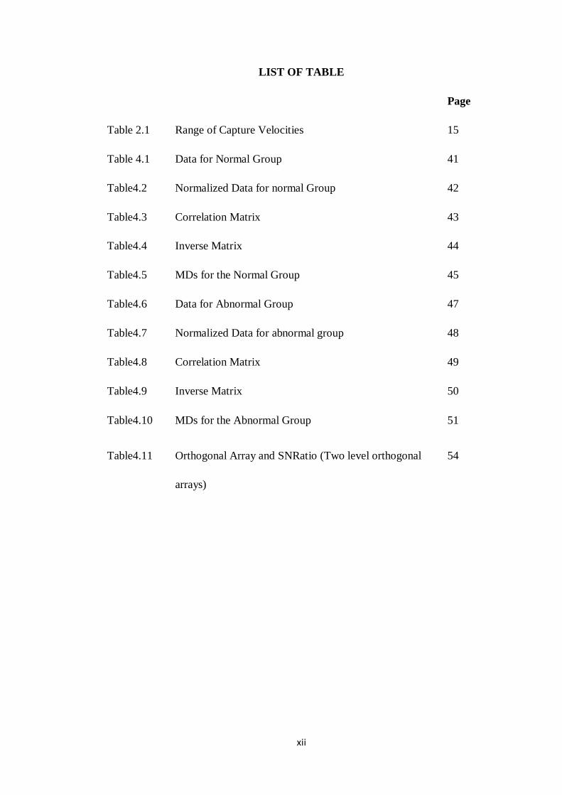
LIST OF TABLE
Page
Table 2.1 Range of Capture Velocities 15
Table 4.1 Data for Normal Group 41
Table4.2 Normalized Data for normal Group 42
Table4.3 Correlation Matrix 43
Table4.4 Inverse Matrix 44
Table4.5 MDs for the Normal Group 45
Table4.6 Data for Abnormal Group 47
Table4.7 Normalized Data for abnormal group 48
Table4.8 Correlation Matrix 49
Table4.9 Inverse Matrix 50
Table4.10 MDs for the Abnormal Group 51
Table4.11 Orthogonal Array and SNRatio (Two level orthogonal 54
arrays)
xiii
LIST OF ABBREVIATIONS
LEV Local Exhaust Ventilation
MD Mahalanobis Distance
MTGS Mahalanobis Taguchi Gram-Schmidt system
MTS Mahalanobis Taguchi System
OA Orthogonal Array
SN Signal to noise
CHAPTER 1
INTRODUCTION
1.1 Background of Study
Malaysia is creating and building a transformation to become a developed nation. By
2020, our prime minister’s target is to transform Malaysia’s economic growth to
quadruple than they were in 1990. Making China as an example, Malaysia has built
many factories to contribute towards the country’s economic growth (New Straits
Times, 2012).In the progress of this development, chemical engineering is one of the
crucial industries in Malaysia as well as manufacturing and electronics.
However when this is in progression, we must not forget the concerns that
must be faced. One of the most vital and important is the health aspects and safety
arena that includes around invisible gases encasing everyone. With the increase of
chemical substances used today in multiple productions, as well as dust particles,
exhaust gases, and other forms of pollution, the users are exposed to harmful air
within long period of time.
2
Because of such harmful matter, the operations in the factories must ensure
that they have effective ventilation. Additionally, maintaining and improving air
quality in your plant or work place should be a concern, as it involves the health of
the users. When it comes to air contaminants, local exhaust ventilation(LEV) is
absolutely required when you have dust, exhaust fumes, solvent vapours, lead fumes,
and acid mist, all known as toxic or corrosive contaminants. If the plant is
contaminants at a high level, it is a must that the output airs need to be filtered out
before being released into the air, because failure to do so can cause other health
problems to the public.
Poor performances of LEV will effect environment directly. The release of
air contaminant will not only pollute the environment affect people as well. In order,
to ensure that LEV system is able to function effectively, ventilation system should
be checked periodically to monitor its performance and detect system malfunction.
Additionally, according to Occupational Safety and Health Act in 1994, LEV
testing and examination is done to control the users exposure to hazardous
substances and contaminants which has been one of the important requirements of
the regulations made under Factories and Machinery Act 1967.LEV system must be
checked within a space of not more than one month by the employer. It also has to be
examined and tested by a registered Hygiene Technician at an interlude not more
than a year.

3
Based on the Figure 1.1 below, it currently lists that face velocities
recommended is below 60 feet per minute (Neuman, 2001). The study shows that there
are still fume hoods that did not pass the criteria, which could be hazardous or even may
cause fatality if it was used. That is why there is a growing need in ensuring easily of the
hood performance which will reduce the health risks at the workplace.
Figure 1.1 Graph of hood performance by Average Face velocity
(Source: Neuman, 2001)
1.2 Problem Statement
As Malaysia is a rapidly developing country, modern industry with a complex of
operation and processes uses increasing number of chemical substances. The workplace
environment may be harmed with various substances such as dusts and chemicals that
could be hazardous if inhaled due to their chemical properties. Many health problems
4
occur as resultants on the exposure to the chemical substances for a long time. Because
of these factors, a well-function system is a mandatory in every factory to increase the
safety level. Essentially, LEV system is installed in every building for heat control and
removal of air contaminant from the area
LEV should be installed in factories or closed building whereas the generation of
air pollutant is generally significant. A typical LEV system works by drawing
contaminated air from a process through a partial enclosure of hood or closed to the
source of emission or contamination.
Nowadays, LEV is installed in every factory but the effectiveness maintenance
and proper design were often overlooked by the factory owner. As a result, the money
spent is wasted and LEV became ineffective. Thus, each of the components of LEV
must be inspected regularly. Periodic testing are required to ensure system performance
is adequate.
In 2009, Chemical Fume Hood Book stated that when installed, fume hoods
should be inspected in accordance with the American Society of Heating, Refrigerating
and Air-Conditioning Engineers ASHRAE 110 to ensure proper containment. Thus, it is
very important in checking the performance of the LEV as it relates to the health and
well-being of the users of LEV (Jafari, 2008).
Based on previous research, there are many ways to inspect performance of LEV
such as tracer gas measurements, smoke release observations, air velocity

5
measurements, face velocity measurement and decay-rate testing under access hoods
(Beamer et al., 2004).
But nowadays, one of the alternative ways of checking the performance of the
LEV in this proposal is by using Mahalanobis approach. Mahalanobis Distance (MD) is
a metric, which is a rule for determining the distance of two points, of a non-spherically
symmetric distribution.
1.3 Research Objectives
The objectives of this study are:
1.3.1 To obtain normal pattern operation of local exhaust ventilation (LEV)
system.
1.3.2 To characterize the pattern to study the performance of the above system.
1.4 Scopes of Study
The evaluation of the performance of LEV System experiment was conducted by
measuring velocity of air flow at evenly distributed points in the plane of the hood face
area of the hood opening. It will then be calculated to see whether the fume hood is
efficient or otherwise. Random points of air flow rates from the same sets of data were
calculated by MD and compared with the initial result.
6
1.5 Significance of Proposed Study
The MD will give a lot of benefit to the engineering field and other fields
involving the usage of LEV system, which is important as an inefficient LEV can be
hazardous and harm the users. This approach can simplify and shorten the time in
checking the performance of the LEV just by using random points of the fume hood air
flow. With this approach, the health and well-being of the users of LEV can be ensured
as the periodic fume hood function inspection can be done easily.
1.6 Expected Outcome
The results from the experiment will give us the characterization pattern of the
LEV. By analysing using MD the result will be similar with the conventional way in
determining the efficiency of the fume hood, thus making the MD a better and faster
way in determining the performance of the fume hood and the LEV system overall.

7
1.7 Concluding Remarks
In this chapter, it had been discussed about the introduction of the research.
Chapter 2 is reviewing about the theoretical of the research and the chapter 3 is
reviewing the methodology of the research, and how the research and experiment was
conducted. Chapter 4 is discussing about the results obtained. Chapter 6 is the summary
of this project.
CHAPTER 2
LITERATURE REVIEW
2.1 Ventilation system
Ventilation is a process of providing fresh air to an enclosed space or area. The
purpose of ventilation is to create a healthy working environment by removing air
contaminants that may be harmful to the users and people surrounds. Ventilation system
is an important aspect of health as a clean supply of air, especially in an enclosed area, is
important for the working environmnent. Many parts of the industries have to involve in
jobs or works that involves dusts, gases or fumes. The main purpose of a ventilation
system is to expell the air contained from a confined space, and replaces them with clean
and fresh air through the system.
In 2001, Goodfellow defined briefly about ventilation in their book, stating that
ventilation uses a competent amount of air flow rate which is as low as it could, to
reduce the impurities when it enters at the points that has been fixed. There

9
are two way in obtaining the low air flow, the first by removing the contaminants
beforehand and the other is by supplying noncontiminated air from an inlet to avoid the
impurities entering the area.In 2002, Energy Efficiency and Renewable Energy
Clearinghouse concluded that ventilation can be divided into three main parts that are
natural ventilation, whole house ventilation and spot ventilation.
2.1.1 Natural ventilation
Natural ventilation is a process where outside air is dragged inside using a
medium of open windows or doors. The principle of natural ventilation is the differences
in the dispersion of air pressures around a building. Basically, air flows from spaces of
high pressure to spaces of low pressure, with gravity and wind pressure affecting it.
Natural ventilation patterns are depending on the location and control of doors and
windows (Energy Efficiency and Renewable Energy Clearinghouse, 2002).
According to HKU Arch in 2001, natural ventilation can be divided into two
categories namely controlled natural ventilation and infiltration. Controlled natural
ventilation is a displacement of air that be done on purpose by using natural forces
through specified openings such as windows and doors. Infiltration can be defined as the
flow of air through non deliberate openings driven by wind, temperature-difference
pressures and/or appliance that is forced by pressures through the building. What makes
it differs from natural controlled ventilation is that infiltration is difficult to be controlled
10
and is not the most popular choice than other ventilation strategies but it is a main source
of ventilation in buildings.
2.1.2 Spot ventilation
Spot ventilation is one of the types of ventilation where the motion of air was
controlled by using localized exhaust fans to rapidly discharge contaminants and
moisture at the feed. Common household examples include range hoods over stoves in
the kitchens and bathroom exhaust fans. Spot ventilation is commonly used in
combination with natural ventilation in order to improve the effectiveness (Energy
Efficiency and Renewable Energy Clearinghouse, 2002).
2.1.3 Whole-house ventilation
A whole-house ventilation system is where one or more fans and duct systems to
supply and insert air to the desired position as to the house. By using this system, it
controls the exchange of inlet and outlet air more efficiently. Whole-house ventilation
consists of two parts, the first one where it may be exhaust-only. The other one is the
supply-only, or other than these two, is the balanced system that is a combination of both
exhaust and fresh air intake substances. Whole-house ventilation systems give
controlled, uniform ventilation within the whole house.

11
There are four types of systems, which are exhaust ventilation systems where
there is force inside air out of a home. The second one is supply ventilation systems,
force outside air into the home. Next is the balanced ventilation system, where the
force has the same amounts quantities of air into and out of the home. And lastly,
energy recovery ventilation systems, where the process consists of heat transfer from
incoming or outgoing air to minimize energy loss.
2.2 Local Exhaust Ventillation System
LEV system is engineering control which to encase and induct the
contaminant materials and also ensuring air flow at an appropriate rate. LEV system
is widely used in many parts of the industry involving an enclosed space or area
(Alden and Kane, 1985).
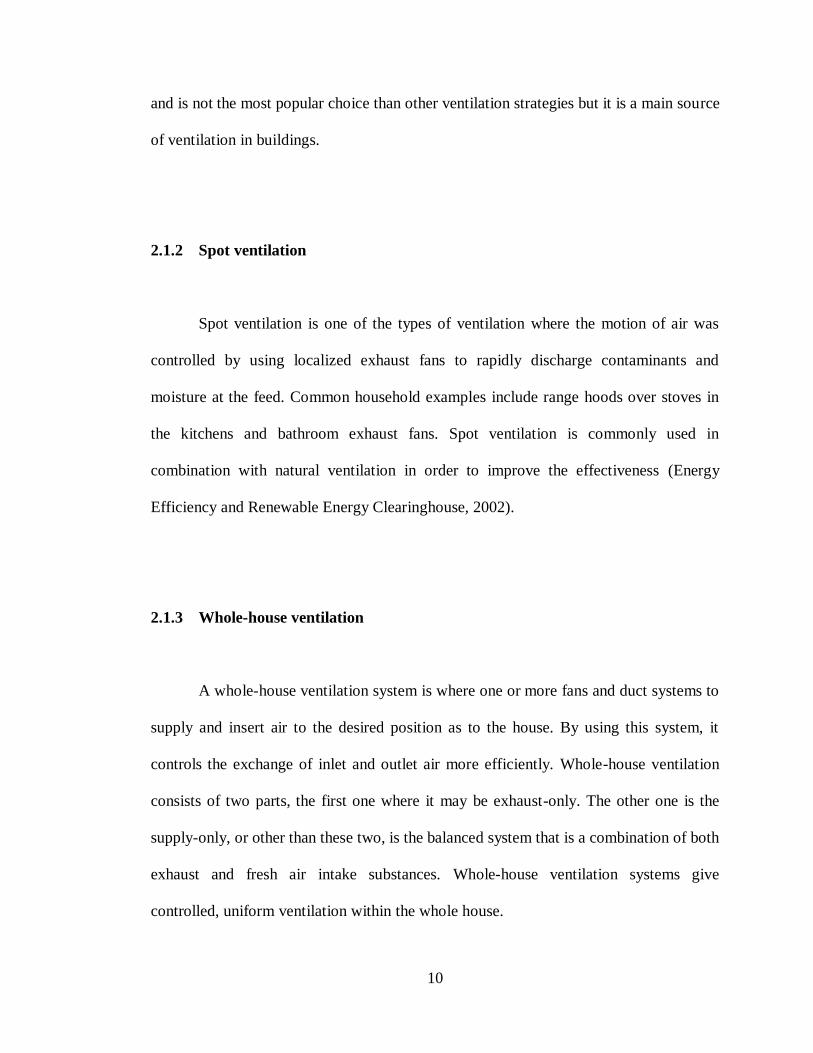
LEV usually consist of four major elements that are hoods, fan, ductwork and
cleaning device. Hoods functioning to capture the air contaminant and fan functions
as the air moving device. Ductwork is to transport the contaminant and lastly air
cleaning device is a collection unit for contaminant. The element in LEV is shown in
Figure 2.1.
12
Figure 2.1 Schematic diagram of LEV
(Source: Mutchler,1973)
2.2.1 Fume Hood
There are many types of local exhaust ventilation system. However,in this
study, fume hood will be used as the subject study of the LEV. The use of a
laboratory fume hood is to decrease chemical exposure. The fume hood will enclose
the perilous substances, the vapours, gases and dusts by removing it via an exhaust
system, where usually at the roof of the building are where the captured air through
the vent.
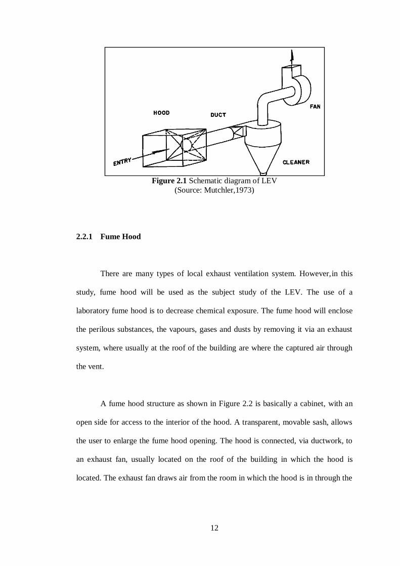
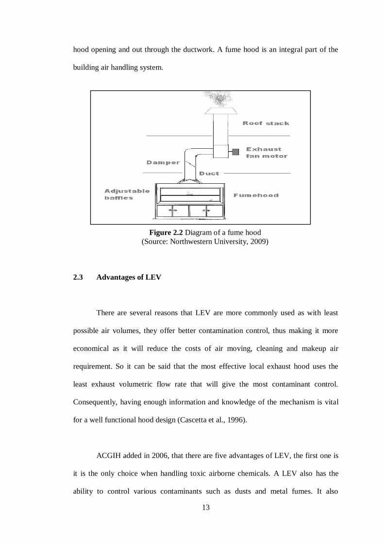
A fume hood structure as shown in Figure 2.2 is basically a cabinet, with an
open side for access to the interior of the hood. A transparent, movable sash, allows
the user to enlarge the fume hood opening. The hood is connected, via ductwork, to
an exhaust fan, usually located on the roof of the building in which the hood is
located. The exhaust fan draws air from the room in which the hood is in through the
13
hood opening and out through the ductwork. A fume hood is an integral part of the
building air handling system.
2.3 Advantages of LEV
There are several reasons that LEV are more commonly used as with least
possible air volumes, they offer better contamination control, thus making it more
economical as it will reduce the costs of air moving, cleaning and makeup air
requirement. So it can be said that the most effective local exhaust hood uses the
least exhaust volumetric flow rate that will give the most contaminant control.
Consequently, having enough information and knowledge of the mechanism is vital
for a well functional hood design (Cascetta et al., 1996).
ACGIH added in 2006, that there are five advantages of LEV, the first one is
it is the only choice when handling toxic airborne chemicals. A LEV also has the
ability to control various contaminants such as dusts and metal fumes. It also
Figure 2.2 Diagram of a fume hood
(Source: Northwestern University, 2009)

14
removes the contaminants in the workplace to ensure the safety of the workers. The
LEV also needs less amount of makeup air because of the exhausted air are in small
quantities. The fifth advantage is that by using LEV, as there is less makeup air to
heat or cool, it will reduce the energy costs.
2.4 Disadvantages of LEV
ACGIH stated in 2006, there are four disadvantages of LEV. The
disadvantages are LEV must be designed concede to industrial hygiene practice to
control the contaminants. Moreover, LEV may have the necessity for a more
excessive cost investment than general ventilation systems to pay for design,
construction and installation materials. The design of LEV may be more complicated
than other ventilation systems as well as it may need more formidable maintenance
organization.
2.5 Conventional ways to study on performance of LEV
Nowadays, there are many chemical substances that are harmful to the user as
well as the environment. People are expose to the contaminated weather without
noticing it. Therefore it is very crucial to study on the performance of the LEV.
There are many conventional ways in evaluating the performance of LEV. Beamer
et.al (2004),describe in their article on how NIOSH field evaluation led to the
invention of recommended testing procedures for evaluations of LEV capture