Embed Size (px)
Citation preview
90
(Read at the Autumn Meeting of The Society of Naval Architects of Japan, November 1987)
A Study on the Effect of Seaquakes
on a Floating Body
by Eiichi Baba*, Member
Summary
Effect of seaquake on a floating body in an open sea and in an enclosed basin was studied
theoretically and experimentally. First, sea bottom and breakwaters were replaced by the
distributions of highly pulsating bubbles, and then formulas for surge, sway and heave ac-
celerations of the floating body were derived in term of the acceleration of sea bottom or
breakwaters. The theoretically predicted responses of the floating body were well supported
by laboratory experiments using a small water tank on a vibrator. From the present study
it was found that the vertical oscillation of large area of sea bottom or of the enclosed basin
of any water depth induces the vertical acceleration on the floating body as if it were on the
ground. Horizontal shake of breakwaters induces both vertical and horizontal accelerations
on the floating body, and their magnitudes decrease substantially with increase of distance
from the breakwaters.
1. Introduction
For seismically active region, seaquake effect on
a floating structure should be considered in the
design process. Hove et al. have reported a num-
ber of well documented cases showing that ships
have been severely damaged or shaken by seismic
waves in the open seal). They have observed as
follows :
( 1 ) Earthquake effects are just as severe to
structures in the open sea as to structures on
ground.
( 2 ) The depth of water has negligible effect on
the damage potential.
( 3 ) In some cases the ship appeared to be lifted
up or out of water
and they have stressed that the damage potential
appears to have such wide distribution in the open
sea as on ground and also pointed out that the
mechanics behind the characteristics of seaquake
are not well explained. Recently, Hagiwara et al.
have conducted a comprehensive experimental study
on the motion responses of a floating power plant
to the seismic activities with a guide based on a
simple hydrodynamic theory2). They used a 1/170
scale model afloat in an enclosed tank (2. 0 m •~ 1. 5
m) fixed on a vibrator. As a result it was observed
as noted by Hove et al. that the vertical accelera-
tion of the body takes the same value as that of
the water tank. Further, they found a ,possibility of isolation from the high frequency horizontal acceleration by taking a distance from the breakwa-ters. At present, as noted by these authors cited above, a hydrodynamic study on the motion re-sponses of a floating body to the seaquake is an area of studies to be pursued for the development of reliable design methodology for floating structures in seismically active regions. The cases presented by Hove et al. were based on the reports from captains and crew who experienced the seaquakes
incidentally. It is, therefore, rather difficult to extract further detail seismological and hydrody-namic information from their reports. Fortunately, however, there is a very rare and invaluable obser- vation by the seismologists Mogi and Mochizuki, who experienced severe seaquakes many times on a hydrographic observation ship, and made detailed measurements of high frequency seismic waves of 50-300 Hz by use of a hydrophone just above the focal region of Izu-Hanto-Toho-Oki Earthquake of M 6. 7 on June 29, 1980.3)
The present author noticed this high frequency
property of seismic waves, and then attempted to model the seismic activities on the sea bottom by distributing pulsating bubbles such as caused by underwater explosion. In fact, most of people, who experienced seaquakes, felt as if their ships were hit by underwater explosions. In the present study, a formula for unsteady force acting on a rigid floating body induced by a pulsating bubble in a water was formulated first and then the sea bottom or breakwaters under seismic activities were
* Nagasaki Experimental Tank , Nagasaki Re-
search and Development Center, Mitsubishi
Heavy Industries, Ltd.
A Study on the Effect of Seaquakes on a Floating Body 91
replaced by the distribution of the pulsating bub-
bles. It turned out that the present theoretical
model explains well the observed responses of float-
ing bodies to the seaquakes.
2. Unsteady forces acting on a
floating body induced by a
pulsating bubble
In 1953 Chertock made a study on the flexural
response of a submerged body to a pulsating gas
bubble4.5). In this study, by using Green's
theorem, analysis was made on the forces acting
on a body in an unsteady incident flow without
having to solve the relevant diffraction problem.
Ogilvie made a generalization of this method and
showed applicability of this method to a wide vari-
ety of hydrodynamic problems5).
For a high frequency fluid motion with free
surface, the so called memory effect due to free-
surface waves is negligible. Therefore, by use of
mirror images with respect to the free-surface, we
may treat the floating body problem as an unbound-
ed fluid problem. In the present study, for the
sake of simplicity, three axial translation modes,
surge, sway and heave of a floating rigid body to
a highly pulsating submerged bubble was considered
following Chertock, who analysed only the vertical
motion for a flexural body. First, it is assumed
that the flow generated by a pulsating bubble is
an incompressible motion. Further it is assumed
that there exists a velocity potential ƒÓ(x,y,z,t)
which satisfies Laplace's equation and is expressed
as a sum of the following two components
( 1 )where ƒÓg represents a motion due to the pulsating
bubble and the second term represents the velocity
potential due to the floating body. qi(t) is the i-
th mode coordinate and qi(t) is the its time deriv-
ative, and got represents i-th mode potential,
where for surge motion, for sway motion
and i=3 for heave motion. With a moving coor-
dinate system as shown in Fig. 1, x-axis coincides
with the direction of surge and y-axis sway and
z-axis heave. The equation of motion of the float-
ing body is written in general :
(2)
where Al is the mass of the floating body, p is the fluid pressure acting on a body with the wetted surface SB, and n is the outward normal vector
from the fluid. The right hand side of the equa-tion (2) is rewritten by use of a relation for an unbounded fluid7) :
( 3 )
where p is the density of water. Substituting (1) into (3), we have from (2) as :
( 4 )
where ni is the i-th component of n. ƒÓg, and ƒÓi
are the solutions of the following boundary value
problem :
Regarding the condition on the bubble surface,
Chertock stated as follows : "The condition aƒÓi/
∂n=0 on G makes φi a function of time as well
as the space coordinates, because the surface G
varies with time. However, the further analysis
is restricted for cases where the bubble is sufficient-
ly far from SB so that its presence has negligible
effect on defining the potential ƒÓi. In that case
φi will be the same as the potential due to the
prescribed motion of SB when the bubble is absent,
and coi can be taken as a function of x, y, z only".
We follow this approximation hereafter.
By use of the relation •ÝƒÓi/•Ýn= ni on SB, the
integral of the second term of the right hand side
of the equation (4) is written as :
( 5 )
where aij is the added mass due to the motion of the floating body. Then the equation (4) is writ-ten as
( 6 )
where it is considered the cases that aij=O fori≒
j.
By use of the Green's second identity to two
functions ƒÓg, and ƒÓi, we have
Fig.1 Coordinate system
92 Journal of The Society of Naval Architects of Japan, Vol.162
Using the boundary conditions stated above, we
have
Here we consider as stated before the case where the distance between the floating body and the bubble is far enough so that we may introduce the following approximations :
i ) the bubble is regarded as a sphere. ii) vg is uniform over the sphere.
Then we have an approximation
where V is the volume of the bubble. coo is the
value of potential ƒÓi at the center of the bubble.
The desired equation of motion of the floating
body is thus obtained from (6) :
( 7 )
To determine the potential ƒÓig of the eq. (7) we
use again the assumption that the distance between
a floating body and a bubble is far enough so that
we may use an asymptotic expression of ƒÓi at the
bubble. Now a potential ƒÓ(x,y,z), which repre-
sents the flow around a floating body and satisfies
ca=-0 at is expressed in general by the Green's
theorem as :
( 8 )where
By defining
and considering a point (x, y, z) far from the float-
ing body, we have a Taylor expansion of (8) up
to the order of O(1/ƒÁ3) as follows : First, we may
obtain the following expansions.
and then,
The first term of the right hand side is a velocity
potential due to a dipole whose axis directs z-axis, and the second and the third terms are higher order and due to quadrupoles, which are composed in such a way that two dipoles, one directing x(or
y)-axis under the free-surface and other directing negative x(or y)-axis above the free-surface, come close together along z-axis. Thus we may assume that in a highly oscillating problem the first term represents heave motion of a floating body, and the second term surge motion and the third term sway motion respectively. Then we may write :
( 9 )
where
where V is the displacement volume, an is added
mass due to surge motion, a22 due to sway motion,
a33 due to heave motion and Ā0 is a representative
value of Ā on the body. Substituting (9) into (7),
we have the following equations for the three
modes of motions :
Surge motion :
Finally, by use of the condition that the body
is floating
we have then the acceleration of the floating body
as :
Surge motion :
Sway motion :
Heave motion :
Finally, by use of the condition that the body
is floating
we have then the acceleration of the floating body
as :
Surge motion :
(10)
Sway motion :
(11)
A Study on the Effect of Seaquakes on a Floating Body 93
Heave motion :
(12)
From these results it is found that the heave
acceleration is determined without any information
of body geometry, while surge and sway motions
depend on the value of Ā0, which is a representa-
tive geometrical parameter of depthwise dimension
of the floating body.
3. Acceleration of a floating body
due to seaquakes
3. 1 Acceleration due to vertical vibration
of sea bottom
In the previous section, the response of a floating body due to an underwater bubble is considered. In the present section, the unsteady vertical motion of sea bottom, which is caused by the so-called P-waves due to seismic activity of ground, is repre-sented by the distribution of pulsating bubbles on the sea bottom.
For the sake of simplicity uniform horizontal sea bottom of depth z= -f is considered. Let the time dependent vertical displacement of sea bottom be defined by h(t). Then a volume dV(t) for an elemental area dxdy is written as :
When a region (x1, yi ; x2, y2) on the sea bottom is displaced, the accelerations of the floating body are expressed for
Surge motion :
(13)
Sway motion :
(14)
Heave motion :
(15)
Further, when the floating body is right above the epicenter, we may put x2= -x1=x0, Y2= -Y1=
Y0 and the surge and sway motions are not caused due to asymmetric character of integrands of (13) and (14), and only the acceleration due to heave motion appears. From the integration of (15), we have
(16)
Even though the floating body is not right above the epicenter, it is understood from the equations
(13) through (15) that the heave motion domi-nates. For a large earthquake the focal region is large
enough so that we may assume
Then, the equation (16) becomes
(17)
This result means that the accerelation of the floating body is the same as that of the sea bottom and the phase of motion is identical with that of the vertical motion of the sea bottom as if the floating body is on the ground, and the effect of sea depth does not appear. Further, since the motion starts from a state of rest, the initial ver-tical displacement of the floating body is the same as that of the sea bottom.
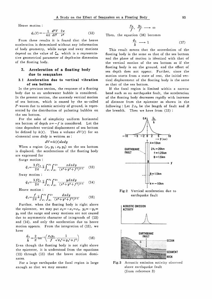
If the focal region is limited within a narrow band such as an earthquake fault, the acceleration of the floating body decreases rapidly with increase of distance from the epicenter as shown in the following : Let 2x0 be the length of fault and B the breadth. Then we have from (15) :
Fig.2 Vertical acceleration due to
earthquake fault
Fig. 3 Acoustic emission activity observed above earthquake fault
(from reference 3)
94 Journal of The Society of Naval Architects of Japan, Vol.162
As an example, use is made of the data of earth-quake fault estimated by Mogi and Mochizuki for the 1980 Izu-Hanto-Toho-Oki Earthquake. They estimated as : 2x0=20 km, B=1.5 km (read from
Fig. 16 of the paper by Mogi and Mochizuki 1980) and f=1. 25 km (read from Fig. 14 of the same paper). Calculated curve of q3/h against the dis-tance y from the center line (y=0) is shown in the upper figure of Fig. 2.
It is observed that the acceleration responses decrease rapidly with the distance from the epicen-ter. This trend agrees well with the trend of the acoustic emission activity observed by Mogi and Mochizuki as shown in Fig. 3.
3.2 Accerelation of a floating body in an
enclosed water basin
3. 2. 1 Vertical shake
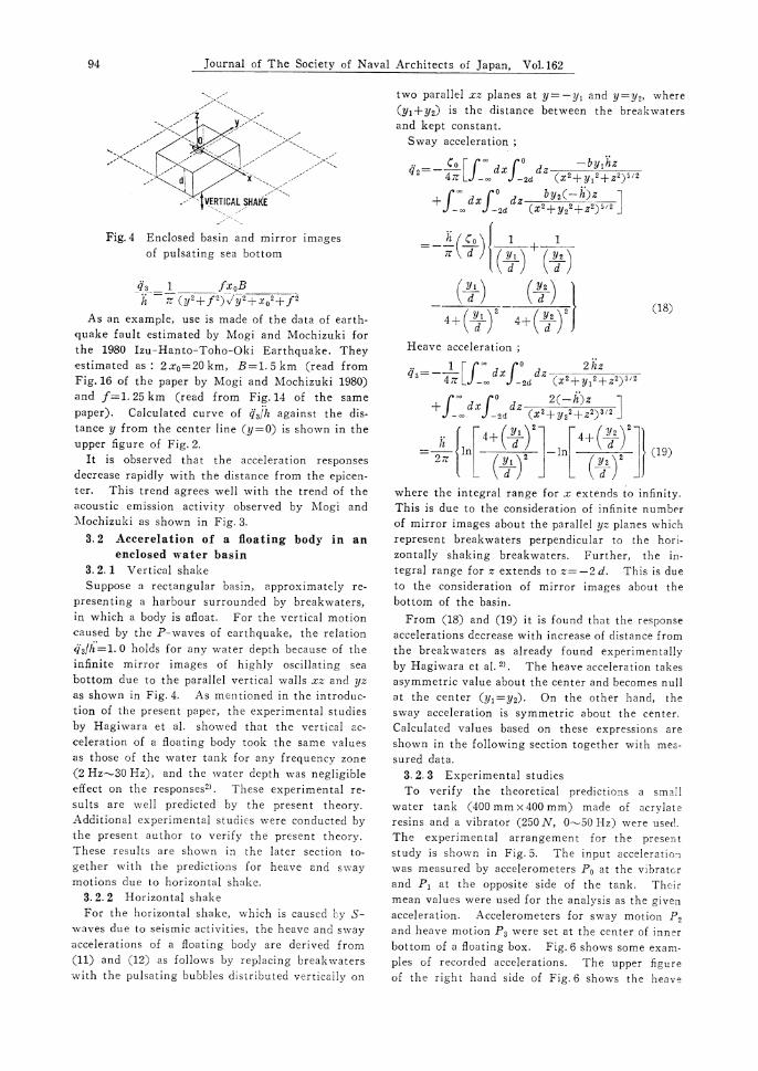
Suppose a rectangular basin, approximately re-
presenting a harbour surrounded by breakwaters, in which a body is afloat. For the vertical motion
caused by the P-waves of earthquake, the relation
q3/h=1.0 holds for any water depth becamse of theinfinite mirror images of highly oscillating sea
bottom due to the parallel vertical walls xz and yz
as shown in Fig. 4. As mentioned in the introduc-
tion of the present paper, the experimental studies
by Hagiwara et al. showed that the vertical ac-
celeration of a floating body took the same values
as those of the water tank for any frequency zone
(2 Hz•`30 Hz), and the water depth was negligible
effect on the responses2). These experimental re-
sults are well predicted by the present theory.
Additional experimental studies were conducted by
the present author to verify the present theory.
These results are shown in the later section to-
gether with the predictions for heave and sway
motions due to horizontal shake.
3. 2. 2 Horizontal shake
For the horizontal shake, which is caused by S-waves due to seismic activities, the heave and sway accelerations of a floating body are derived from
(11) and (12) as follows by replacing breakwaters with the pulsating bubbles distributed vertically on
two parallel xz planes at y=-y1 and y=y2, where
(y1+y2) is the distance between the breakwaters and kept constant.
Sway acceleration ;
(18)
Heave acceleration ;
(19)
where the integral range for x extends to infinity.
This is due to the consideration of infinite number
of mirror images about the parallel yz planes which
represent breakwaters perpendicular to the hori-
zontally shaking breakwaters. Further, the in-
tegral range for z extends to z= -2 d. This is due
to the consideration of mirror images about the
bottom of the basin.
From (18) and (19) it is found that the response
accelerations decrease with increase of distance from
the breakwaters as already found experimentally
by Hagiwara et al. 2) . The heave acceleration takes
asymmetric value about the center and becomes null
at the center (y1=Y2). On the other hand, the
sway acceleration is symmetric about the center.
Calculated values based on these expressions are
shown in the following section together with mea-
sured data.
3. 2. 3 Experimental studies
To verify the theoretical predictions a small
water tank (400 mm •~ 400 mm) made of acrylate
resins and a vibrator (250 N, 0•`50 Hz) were used.
The experimental arrangement for the present
study is shown in Fig. 5. The input acceleration
was measured by accelerometers Po at the vibrator
and P1 at the opposite side of the tank. Their
mean values were used for the analysis as the given
acceleration. Accelerometers for sway motion P,
and heave motion P3 were set at the center of inner
bottom of a floating box. Fig. 6 shows some exam-
ples of recorded accelerations. The upper figure
of the right hand side of Fig. 6 shows the heave
Fig. 4 Enclosed basin and mirror images
of pulsating sea bottom

A Study on the Effect of Seaquakes on a Floating Body 95
acceleration due to vertical shake. As the theory
predicts, the amplitude and phase of response ac- celeration are almost the same as those of given acceleration. The quantitative evaluation is given later. The figures in the left hand side of Fig. 6 shows a comparison of response accelerations for three different positions of the floating body. The heave acceleration at the center (horizontal shake A) is almost negligible as the theory predicts and the small value of sway acceleration is observed. In the records of horizontal shake B and C, the
position of the floating body is opposite about the center of the tank. As the theory predicts, the sign of heave acceleration changes for these two
points, while the sway acceleration keeps the same phase and amplitude of response. From the com-parison of horizontal shake B and D, it is observed. that the smaller water depth d gives smaller re- sponse accelerations.
In the followings quantitative comparisons be-
tween the predicted and measured values are made.
Fig. 7 shows the ratio of heave acceleration to the
given acceleration for vertical shake. The posi-
tions of the floating body are changed. Though a
little higher values are observed near the walls,
the experimental data agree well with the given
acceleration as a whole, and are independent of
water depth and frequency. Fig. 8 through Fig. 11
show the comparisons between the predicted and
measured accelerations in the case of horizontal
shake. Calculations were made based on the ex-
pressions (18) and (19). In calculating sway ac-
celeration Ā0 is assumed to be one half of the draft
T of a floating body, viz., Ā0= - T/2. Fig. 8 shows
the effect of water depth on motion responses.
The shallower draft gives lower values of heave
and sway accelerations. The theoretical values
agree qualitatively with measurements. However
quantitative agreement becomes poorer towards the
walls. This may be due to the approximation
employed in the present theory, which has been
developed under the assumption that the floating
Fig. 5 Arrangement for experimental study
Fig. 6 Records of acceleration measurements
Fig. 7 Comparison of calculated and
measured heave acceleration
in vertical shake
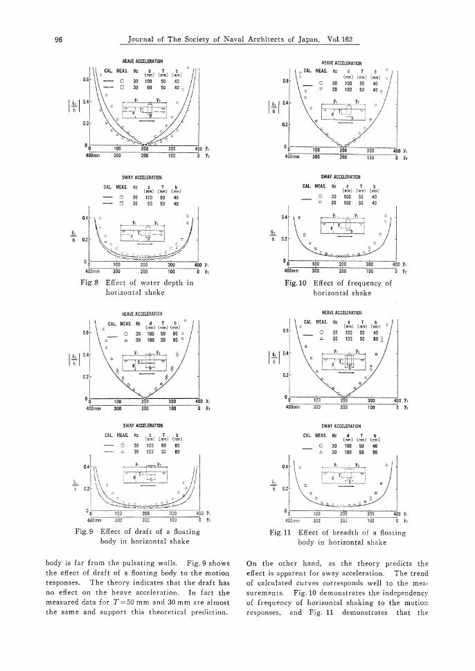
96 Journal of The Society of Naval Architects of Japan, Vol.162
body is far from the pulsating walls. Fig. 9 shows
the effect of draft of a floating body to the motion
responses. The theory indicates that the draft has
no effect on the heave acceleration. In fact the
measured data for T=50 mm and 30 mm are almost
the same and support this theoretical prediction.
On the other hand, as the theory predicts the
effect is apparent for sway acceleration. The trend
of calculated curves corresponds well to the mea-
surements. Fig. 10 demonstrates the independency
of frequency of horizontal shaking to the motion
responses, and Fig. 11 demonstrates that the
Fig.8 Effect of water depth in
horizontal shake
Fig. 9 Effect of draft of a floating
body in horizontal shake
Fig.10 Effect of frequency of
horizontal shake
Fig.11 Effect of breadth of a floating
body in horizontal shake
A Study on the Effect of Seaquakes on a Floating Body 97
changes of breadth of floating body used in the
present study has negligible effect on motion re-
sponses. These experiments also support the theoret-
ical predictions, viz., the phase of oscillation in-
duced on a floating body takes the same value as
that of the breakwater, and the accelerations are
independent of the breadth of the floating body.
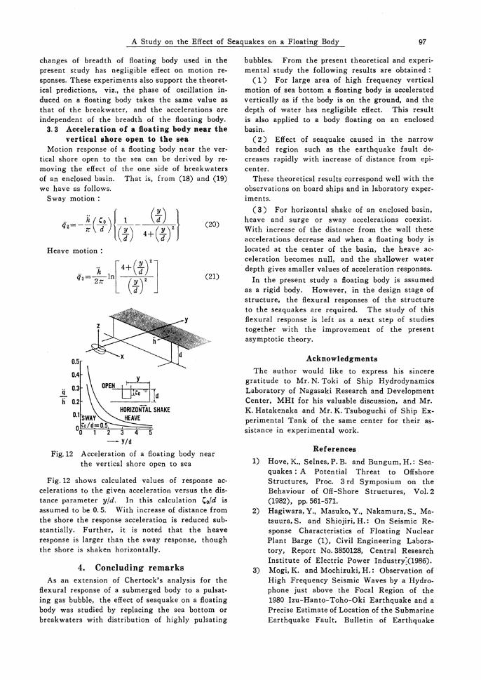
3.3 Acceleration of a floating body near the
vertical shore open to the sea
Motion response of a floating body near the ver- tical shore open to the sea can be derived by re- moving the effect of the one side of breakwaters of an enclosed basin. That is, from (18) and (19) we have as follows.
Sway motion :
(20)
Heave motion :
(21)
Fig. 12 shows calculated values of response ac-
celerations to the given acceleration versus the dis-
tance parameter y/d. In this calculation Ā0/d is
assumed to be 0.5. With increase of distance from
the shore the response acceleration is reduced sub-
stantially. Further, it is noted that the heave
response is larger than the sway response, though
the shore is shaken horizontally.
4. Concluding remarks
As an extension of Chertock's analysis for the
flexural response of a submerged body to a pulsat-
ing gas bubble, the effect of seaquake on a floating
body was studied by replacing the sea bottom or
breakwaters with distribution of highly pulsating
bubbles. From the present theoretical and experi-mental study the following results are obtained :
( 1 ) For large area of high frequency vertical motion of sea bottom a floating body is accelerated vertically as if the body is on the ground, and the depth of water has negligible effect. This result is also applied to a body floating on an enclosed basin.
( 2 ) Effect of seaquake caused in the narrow banded region such as the earthquake fault de-creases rapidly with increase of distance from epi-center. These theoretical results correspond well with the observations on board ships and in laboratory exper-iments.
( 3 ) For horizontal shake of an enclosed basin, heave and surge or sway accelerations coexist. With increase of the distance from the wall these accelerations decrease and when a floating body is located at the center of the basin, the heave ac- celeration becomes null, and the shallower water depth gives smaller values of acceleration responses.
In the present study a floating body is assumed as a rigid body. However, in the design stage of structure, the flexural responses of the structure to the seaquakes are required. The study of this flexural response is left as a next step of studies together with the improvement of the present asymptotic theory.
Acknowledgments
The author would like to express his sincere
gratitude to Mr. N. Toki of Ship Hydrodynamics Laboratory of Nagasaki Research and Development
Center, MHI for his valuable discussion, and Mr.
K. Hatakenaka and Mr. K. Tsuboguchi of Ship Ex-
perimental Tank of the same center for their as-sistance in experimental work.
References
1) Hove, K., Selnes, P. B. and Bungum, H.: Sea-
quakes : A Potential Threat to Offshore Structures, Proc. 3 rd Symposium on the
Behaviour of Off-Shore Structures, Vol. 2
(1982), pp. 561-571. 2) Hagiwara, Y., Masuko, Y., Nakamura, S., Ma-
tsuura, S. and Shiojiri, H.: On Seismic Re-sponse Characteristics of Floating Nuclear
Plant Barge (1), Civil Engineering Labora-tory, Report No. 3850128, Central Research
Institute of Electric Power Industry(1986). 3) Mogi, K. and Mochizuki, H.: Observation of
High Frequency Seismic Waves by a Hydro-
phone just above the Focal Region of the 1980 Izu-Hanto-Toho-Oki Earthquake and a
Precise Estimate of Location of the Submarine Earthquake Fault, Bulletin of Earthquake
Fig.12 Acceleration of a floating body near
the vertical shore open to sea
98 Journal of The Society of Naval Architects of Japan, Vol. 162
Research Institute, University of Tokyo, Vol. 55 (1980), pp. 1017-1041.
4) Chertock, G.: The Flexural Responses of a Submerged Solid to a Pulsating Gas Bubble,
Journal of Applied Physics, Vol. 24, No. 2
(1953), pp. 192-197. 5) Chertock, G.: Transient Flexural Vibrations
of Ship-Like Structures Exposed to Under-water Explosions, The Journal of the Acous-
tical Society of America, Vol. 48, No. 1 (Part 2), (1970), pp. 170-180.
6) Ogilvie, T. F.: The Chertock Formula for Computing Unsteady Fluid Dynamic Force
on a Body, ZAMM, Vol. 55 (1973), pp. 573- 582.
7) Newman, J. N.: Marine Hydrodynamics, The MIT Press, (1977).