Embed Size (px)
Citation preview
A Study on Dynamic Properties of Composite Metal Foams
by Afsaneh Rabiei and Vincent H. Hammond
ARL-CR-706 December 2012 Approved for public release; distribution is unlimited.

NOTICES
Disclaimers The findings in this report are not to be construed as an official Department of the Army position unless so designated by other authorized documents. Citation of manufacturer’s or trade names does not constitute an official endorsement or approval of the use thereof. Destroy this report when it is no longer needed. Do not return it to the originator.
Army Research Laboratory Aberdeen Proving Ground, MD 21005-5069
ARL-CR-706 December 2012 A Study on Dynamic Properties of Composite Metal Foams
Vincent H. Hammond Weapons and Materials Research Directorate, ARL
Afsaneh Rabiei North Carolina State University
Approved for public release; distribution is unlimited.
ii
REPORT DOCUMENTATION PAGE Form Approved OMB No. 0704-0188
Public reporting burden for this collection of information is estimated to average 1 hour per response, including the time for reviewing instructions, searching existing data sources, gathering and maintaining the data needed, and completing and reviewing the collection information. Send comments regarding this burden estimate or any other aspect of this collection of information, including suggestions for reducing the burden, to Department of Defense, Washington Headquarters Services, Directorate for Information Operations and Reports (0704-0188), 1215 Jefferson Davis Highway, Suite 1204, Arlington, VA 22202-4302. Respondents should be aware that notwithstanding any other provision of law, no person shall be subject to any penalty for failing to comply with a collection of information if it does not display a currently valid OMB control number. PLEASE DO NOT RETURN YOUR FORM TO THE ABOVE ADDRESS. 1. REPORT DATE (DD-MM-YYYY)
December 2012 2. REPORT TYPE
Final 3. DATES COVERED (From - To)
June 2010–August 2011 4. TITLE AND SUBTITLE
A Study on Dynamic Properties of Composite Metal Foams 5a. CONTRACT NUMBER
W911NF-10-1-0142 5b. GRANT NUMBER
5c. PROGRAM ELEMENT NUMBER
6. AUTHOR(S)
Afsaneh Rabiei* and Vincent Hammond 5d. PROJECT NUMBER
5e. TASK NUMBER
5f. WORK UNIT NUMBER
7. PERFORMING ORGANIZATION NAME(S) AND ADDRESS(ES)
U.S. Army Research Laboratory ATTN: RDRL-WMM-F Aberdeen Proving Ground, MD 21005-5069
8. PERFORMING ORGANIZATION REPORT NUMBER
ARL-CR-706
9. SPONSORING/MONITORING AGENCY NAME(S) AND ADDRESS(ES)
10. SPONSOR/MONITOR’S ACRONYM(S) 11. SPONSOR/MONITOR'S REPORT NUMBER(S)
12. DISTRIBUTION/AVAILABILITY STATEMENT
Approved for public release; distribution is unlimited.
13. SUPPLEMENTARY NOTES *Department of Mechanical and Aerospace Engineering, Raleigh, NC 27695
14. ABSTRACT
Composite metal foam is a new class of closed cell metal foam offering higher energy absorption compared to the monolithic material at approximately one-third of the density. The superior energy absorption capability of composite metal foam makes this material a potential candidate for structural components such as automotive crash box and crumple zones. However, a systematic study on the dynamic properties of composite metal foams is necessary before they can be utilized in vehicular structures. It has been reported that the energy absorption of other metal foams will increase by increasing the strain rate up to 4× at impact speeds of up to 200 m/s. In this study, the dynamic properties of composite metal foams under various impact speeds are obtained through a variety of experimental techniques. Subsequently, there results are compared to those published in the literature for other foams tested at various impact rates. 15. SUBJECT TERMS
composite metal foams, steel, high strain rate testing
16. SECURITY CLASSIFICATION OF: 17. LIMITATION OF ABSTRACT
UU
18. NUMBER OF PAGES
18
19a. NAME OF RESPONSIBLE PERSON Vincent H. Hammond
a. REPORT
Unclassified b. ABSTRACT
Unclassified c. THIS PAGE
Unclassified 19b. TELEPHONE NUMBER (Include area code) 410-306-0668
Standard Form 298 (Rev. 8/98) Prescribed by ANSI Std. Z39.18
iii
Contents
List of Figures iv
List of Tables v
1. Introduction 1
2. Experimental Procedure/Materials and Method 1
2.1 Materials and Processing .................................................................................................1
2.2 Structural Analysis ..........................................................................................................2
2.3 Quasi-Static and Dynamic Compression Testing Procedure ..........................................2
2.4 Split Hopkinson Pressure Bar..........................................................................................3
3. Results and Discussion 3
3.1 Structural Properties ........................................................................................................3
3.2 Mechanical Properties .....................................................................................................6
4. Conclusions 7
5. References 8
List of Symbols, Abbreviations, and Acronyms 9
Distribution List 10
iv
List of Figures
Figure 1. (A), (B) and (C) Digital images of the composite foam with 2.2-, 4- and 5.2-mm sphere diameters, (D), (E) and F) corresponding SEM images of the area highlighted with the box in each image respectively. ...........................................................................................4
Figure 2. Surface features of hollow spheres (A), and the presence of limited debonding at the interface (B). ........................................................................................................................5
Figure 3. Stress-strain curve for samples with various sphere sizes under various loading speeds. ........................................................................................................................................6
Figure 4. Comparison of the yield strength (left) and elastic modulus (right) of CMF at various speeds. ...........................................................................................................................7
v
List of Tables
Table 1. Physical properties and chemical composition of hollow spheres and the matrix material. .....................................................................................................................................2
Table 2. Composition of various features in 2.2-mm sphere CMF before and after processing. .................................................................................................................................4
Table 3. Compositional changes for selected elements after processing for foams with indicated sphere size. .................................................................................................................5

vi
INTENTIONALLY LEFT BLANK.
1
1. Introduction
Composite Metal Foam (CMF) is a cellular material developed at North Carolina State University consisting of a random loose arrangement of hollow metal spheres embedded in a metallic matrix. Quasi-static compression testing shows a uniform deformation behavior without the presence of localized collapse bands, resulting in a high plateau strength in the range of 50–150 MPa depending on the material and processing methods (1). Composite metal foams have also been tested extensively under compression-compression fatigue, loading-unloading compression, and 4 point bending (2–8). However, their behavior at higher loading rates has never been tested.
Excluding a singular exception (9), most of the studies on high strain rate loading of metal foams in the literature report an increased yield and plateau strength as the loading rate increases for foams made from aluminum (10–12), steel (13), and hollow sphere structures (14, 15). The strain rate effect on metal foams is explained as a combination of compressed air trapped inside the cells during impact, micro-inertial effects of the cell walls, and strain rate sensitivity of the cell wall material (12), although some differences exist in the literature as to which of these effects is dominant. A few studies have tested Al foams at higher speeds up to 210 m/s, and report an additional shock phenomena that dominates the foam’s behavior above a critical velocity (16, 17). This “critical” velocity appears to depend on foam properties, such as density (17), and for some foams it is reported as low as 50–55 m/s (18). In this study, steel composite foams, processed using powder metallurgy technique with a variety of spheres sizes, are tested at several loading rates up to 28 m/s using servo-hydraulic machine and Split Hopkinson Pressure Bar apparatus.
2. Experimental Procedure/Materials and Method
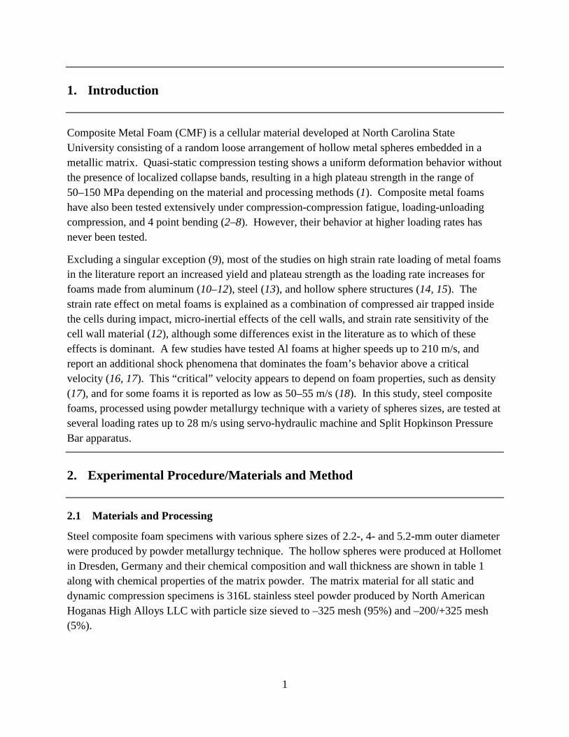
2.1 Materials and Processing
Steel composite foam specimens with various sphere sizes of 2.2-, 4- and 5.2-mm outer diameter were produced by powder metallurgy technique. The hollow spheres were produced at Hollomet in Dresden, Germany and their chemical composition and wall thickness are shown in table 1 along with chemical properties of the matrix powder. The matrix material for all static and dynamic compression specimens is 316L stainless steel powder produced by North American Hoganas High Alloys LLC with particle size sieved to –325 mesh (95%) and –200/+325 mesh (5%).
2
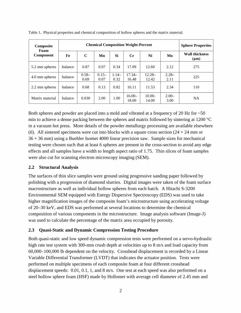
Table 1. Physical properties and chemical composition of hollow spheres and the matrix material.
Composite Foam
Component
Chemical Composition Weight-Percent Sphere Properties
Fe C Mn Si Cr Ni Mo Wall thickness (μm)
5.2 mm spheres balance 0.87 0.07 0.34 17.09 12.60 2.12 275
4.0 mm spheres balance 0.58–0.69
0.15–0.07
1.14–0.32
17.34–16.48
12.28–12.42
2.28–2.11 225
2.2 mm spheres balance 0.68 0.13 0.82 16.11 11.53 2.34 110
Matrix material balance 0.030 2.00 1.00 16.00–18.00
10.00-14.00
2.00–3.00 NA
Both spheres and powder are placed into a mold and vibrated at a frequency of 20 Hz for ~50 min to achieve a dense packing between the spheres and matrix followed by sintering at 1200 °C in a vacuum hot press. More details of the powder metallurgy processing are available elsewhere (6). All sintered specimens were cut into blocks with a square cross section (24 × 24 mm or 36 × 36 mm) using a Buehler Isomet 4000 linear precision saw. Sample sizes for mechanical testing were chosen such that at least 6 spheres are present in the cross-section to avoid any edge effects and all samples have a width to length aspect ratio of 1.75. Thin slices of foam samples were also cut for scanning electron microscopy imaging (SEM).
2.2 Structural Analysis
The surfaces of thin slice samples were ground using progressive sanding paper followed by polishing with a progression of diamond slurries. Digital images were taken of the foam surface macrostructure as well as individual hollow spheres from each batch. A Hitachi S-3200 Environmental SEM equipped with Energy Dispersive Spectroscopy (EDS) was used to take higher magnification images of the composite foam’s microstructure using accelerating voltage of 20–30 keV, and EDS was performed at several locations to determine the chemical composition of various components in the microstructure. Image analysis software (Image-J) was used to calculate the percentage of the matrix area occupied by porosity.
2.3 Quasi-Static and Dynamic Compression Testing Procedure
Both quasi-static and low speed dynamic compression tests were performed on a servo-hydraulic high rate test system with 300-mm crush depth at velocities up to 8 m/s and load capacity from 60,000–100,000 lb dependent on the velocity. Crosshead displacement is recorded by a Linear Variable Differential Transformer (LVDT) that indicates the actuator position. Tests were performed on multiple specimens of each composite foam at four different crosshead displacement speeds: 0.01, 0.1, 1, and 8 m/s. One test at each speed was also performed on a steel hollow sphere foam (HSF) made by Hollomet with average cell diameter of 2.45 mm and
3
specimen dimensions 23 × 23 × 40 mm for comparison. High speed video was recorded from each test at 500–10000 fps depending on impact speed.
2.4 Split Hopkinson Pressure Bar
Another batch of stainless steel composite foam samples was tested using Split Hopkinson Pressure Bar (SHPB) technique. Cylindrical specimens were manufactured through the powder metallurgy technique described previously using 2.2-mm diameter stainless steel spheres and 316L stainless steel powder, similar to those explained in section 2.1. The diameter of the SHPB specimens was 19 mm with 9.53-mm length for an L/D ratio of 0.5. The SHPB used 19-mm diameter aluminum incident and transmitted bars and a striker bar 177.8-mm long. Air pressure on the gas gun ranged from 50–100 psi to achieve strain rates up to 2770 s-1 (26.4 m/s). Data was reduced to calculate the stress-strain material response through the 2-wave analysis method and high speed video was recorded at 96,000 fps.
3. Results and Discussion
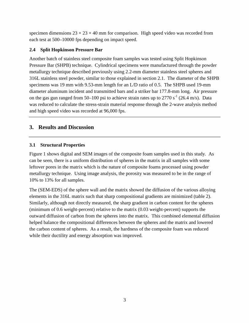
3.1 Structural Properties Figure 1 shows digital and SEM images of the composite foam samples used in this study. As can be seen, there is a uniform distribution of spheres in the matrix in all samples with some leftover pores in the matrix which is the nature of composite foams processed using powder metallurgy technique. Using image analysis, the porosity was measured to be in the range of 10% to 13% for all samples.
The (SEM-EDS) of the sphere wall and the matrix showed the diffusion of the various alloying elements in the 316L matrix such that sharp compositional gradients are minimized (table 2). Similarly, although not directly measured, the sharp gradient in carbon content for the spheres (minimum of 0.6 weight-percent) relative to the matrix (0.03 weight-percent) supports the outward diffusion of carbon from the spheres into the matrix. This combined elemental diffusion helped balance the compositional differences between the spheres and the matrix and lowered the carbon content of spheres. As a result, the hardness of the composite foam was reduced while their ductility and energy absorption was improved.
4
Figure 1. (A), (B) and (C) Digital images of the composite foam with 2.2-, 4- and 5.2-mm sphere diameters,
(D), (E) and F) corresponding SEM images of the area highlighted with the box in each image respectively.
Table 2. Composition of various features in 2.2-mm sphere CMF before and after processing.
Feature Fe C Mn Si Cr Ni Mo
Before processing
Hollow spheres Balance 0.68 0.13 0.82 16.11 11.53 2.34 316L powder Balance 0.03 2.00 1.00 16–18 10–14 2–3
After processing
Sphere wall Balance NA 0.21 0.77 15.54 12.49 1.92 Sphere/matrix interface Balance NA 0.23 0.283 16.46 13.85 1.57
Matrix Balance NA 0.07 0.31 16.73 14.17 1.12
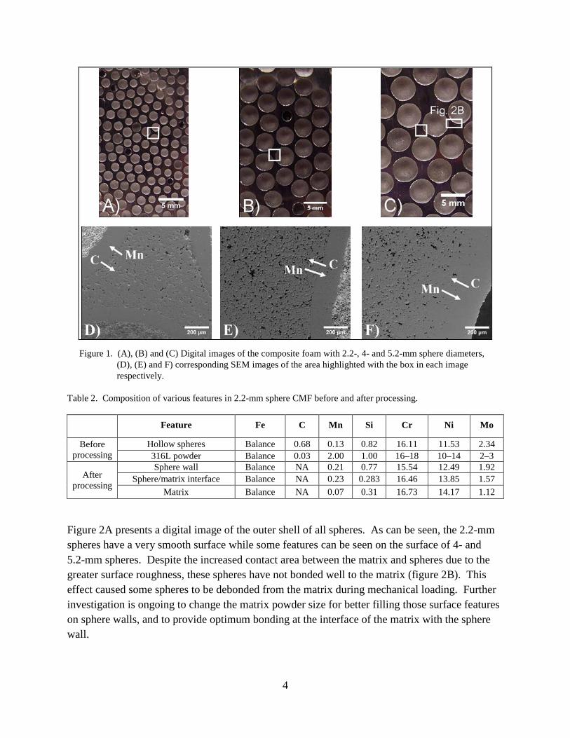
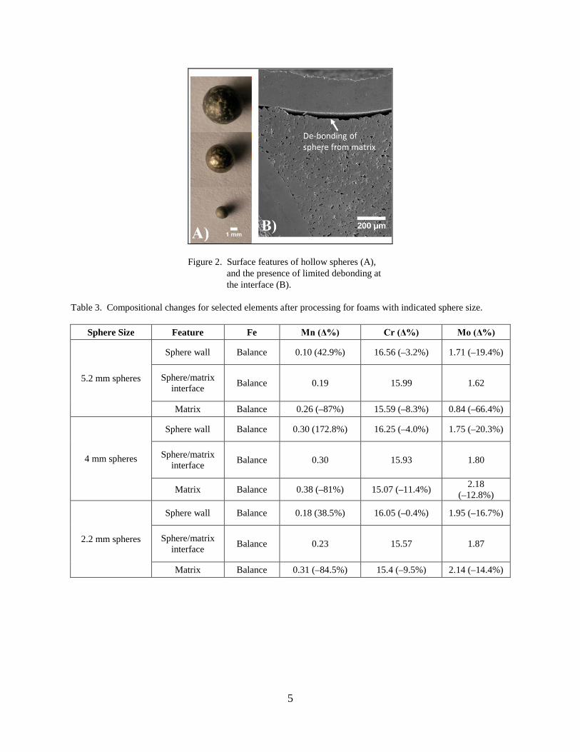
Figure 2A presents a digital image of the outer shell of all spheres. As can be seen, the 2.2-mm spheres have a very smooth surface while some features can be seen on the surface of 4- and 5.2-mm spheres. Despite the increased contact area between the matrix and spheres due to the greater surface roughness, these spheres have not bonded well to the matrix (figure 2B). This effect caused some spheres to be debonded from the matrix during mechanical loading. Further investigation is ongoing to change the matrix powder size for better filling those surface features on sphere walls, and to provide optimum bonding at the interface of the matrix with the sphere wall.
5
Figure 2. Surface features of hollow spheres (A), and the presence of limited debonding at the interface (B).
Table 3. Compositional changes for selected elements after processing for foams with indicated sphere size.
Sphere Size Feature Fe Mn (Δ%) Cr (Δ%) Mo (Δ%)
5.2 mm spheres
Sphere wall Balance 0.10 (42.9%) 16.56 (–3.2%) 1.71 (–19.4%)
Sphere/matrix interface Balance 0.19 15.99 1.62
Matrix Balance 0.26 (–87%) 15.59 (–8.3%) 0.84 (–66.4%)
4 mm spheres
Sphere wall Balance 0.30 (172.8%) 16.25 (–4.0%) 1.75 (–20.3%)
Sphere/matrix interface Balance 0.30 15.93 1.80
Matrix Balance 0.38 (–81%) 15.07 (–11.4%) 2.18 (–12.8%)
2.2 mm spheres
Sphere wall Balance 0.18 (38.5%) 16.05 (–0.4%) 1.95 (–16.7%)
Sphere/matrix interface Balance 0.23 15.57 1.87
Matrix Balance 0.31 (–84.5%) 15.4 (–9.5%) 2.14 (–14.4%)

6
3.2 Mechanical Properties
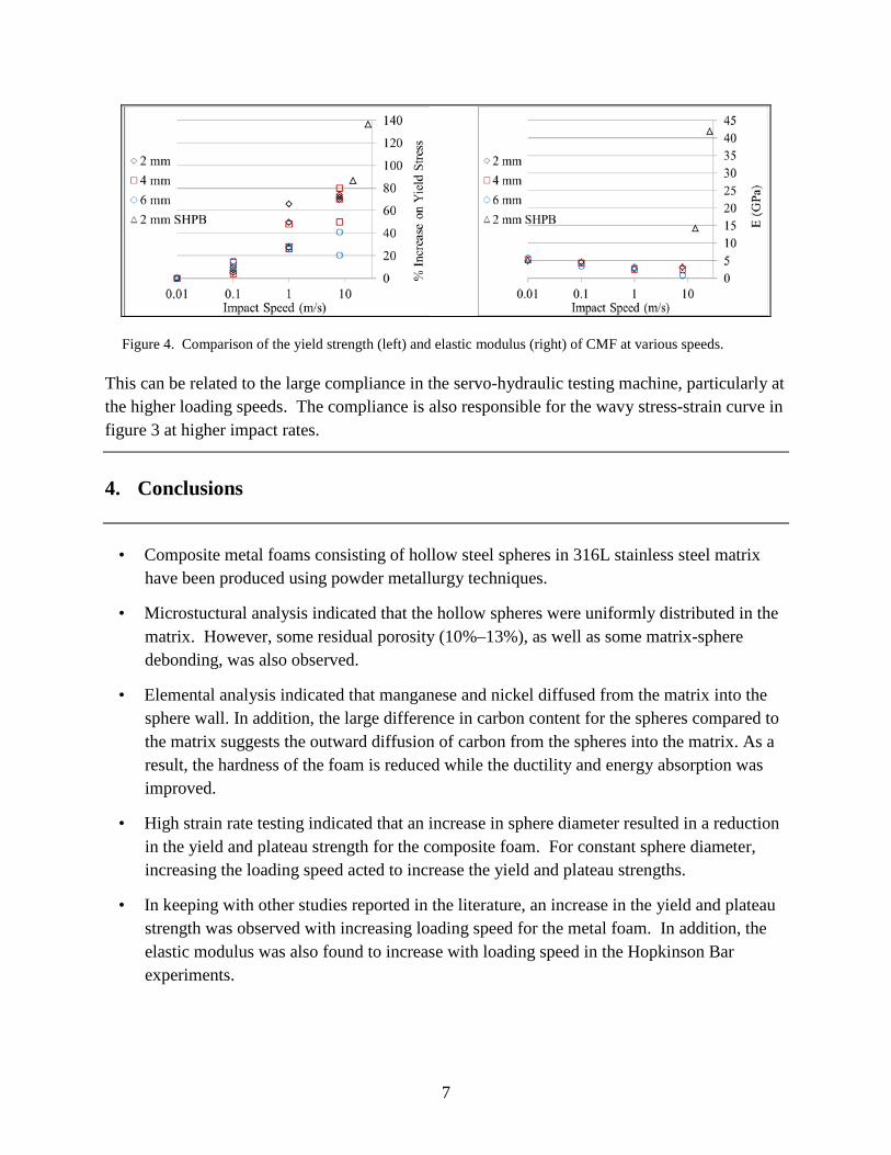
Figure 3 presents the stress-strain curve of composite foams with various sphere sizes tested under various loading speeds. Figures 4A and B compare the yield strength and modulus of elasticity of all samples at various speeds. As can be seen, both the yield and plateau strength of all composite foams is decreased by increasing the spheres diameter whereas an increase in the loading speed increased the yield and plateau strength of the material. As the result, the highest strength belonged to the composite foams made out of the 2-mm spheres tested under 25 m/s loading speed. In addition, a distinct increase is also observed in the plateau stress when the response of the composite foams is compared with a sintered sphere-only perform of similar material and sphere dimensions. This shows the importance of the matrix in bonding the spheres together and reinforcing the sphere walls under loading.
Figure 3. Stress-strain curve for samples with various sphere sizes under various loading speeds.
It is notable that an improvement of 80% to 140% is observed in the yield strength of the composite foam samples made with 2-mm hollow spheres and tested under SHPB. This is in agreement with previous reports that an increase in the loading speed can increase the yield and plateau strength of metal foams. Comparing the modulus of elasticity of the samples tested in servo-hydraulic testing machine shows a decrease in modulus with increasing loading speed from 0.01 to 8 m/s. However, results from those tests using Hopkinson Bar techniques show a completely opposite relationship, namely an increase in modulus with increasing loading speed.
7
Figure 4. Comparison of the yield strength (left) and elastic modulus (right) of CMF at various speeds.
This can be related to the large compliance in the servo-hydraulic testing machine, particularly at the higher loading speeds. The compliance is also responsible for the wavy stress-strain curve in figure 3 at higher impact rates.
4. Conclusions
• Composite metal foams consisting of hollow steel spheres in 316L stainless steel matrix have been produced using powder metallurgy techniques.
• Microstuctural analysis indicated that the hollow spheres were uniformly distributed in the matrix. However, some residual porosity (10%–13%), as well as some matrix-sphere debonding, was also observed.
• Elemental analysis indicated that manganese and nickel diffused from the matrix into the sphere wall. In addition, the large difference in carbon content for the spheres compared to the matrix suggests the outward diffusion of carbon from the spheres into the matrix. As a result, the hardness of the foam is reduced while the ductility and energy absorption was improved.
• High strain rate testing indicated that an increase in sphere diameter resulted in a reduction in the yield and plateau strength for the composite foam. For constant sphere diameter, increasing the loading speed acted to increase the yield and plateau strengths.
• In keeping with other studies reported in the literature, an increase in the yield and plateau strength was observed with increasing loading speed for the metal foam. In addition, the elastic modulus was also found to increase with loading speed in the Hopkinson Bar experiments.
8
5. References
1. Rabiei, A.; Vendra, L. J. Mater. Lett. 2009, 63, 533.
2. Rabiei, A.; Neville, B.; Reese, N.; Vendra, L. Mater. Sci. Forum 2007, 1868.
3. Rabiei, A.; Vendra, L.; Reese, N.; Young, N.; Neville, B. P. Mater. Trans. 2006, 47, 2148.
4. Rabiei, A.; O’Neill, A. T. Mater. Sci. Eng. A. 2005, 404, 159.
5. Vendra, L. J.; Rabiei, A. Mater. Sci. Eng. A. 2010, 527, 1784.
6. Neville, B. P.; Rabiei, A. Mater. Des. 2008, 29, 388.
7. Brown, J. A.; Vendra, L. J.; Rabiei, A. Met. Mater. Trans. A. 2010, 41A, 2784.
8. Vendra, L. J.; Brown, J. A.; Rabiei, A. J. Mat. Sci. 2011, 46, 4574.
9. Deshpande, V. S.; Fleck, N. A. Int. J. Impact. Eng. 2000, 24, 277.
10. Mukai, T.; Kanahashi, H.; Miyoshi, T.; Mabuchi, M.; T. Nieh, G.; Higashi, K. Scripta Mater. 1999, 40.
11. Sadot, O.; Antegy, I.; Harush, S.; Levintant, O.; Nizri, E.; Ostraich, B.; Schenker, A.; Gal, E.; Kivity, Y.; Ben-Dor, G. J. Struct. Eng. 2005, 131, 1226.
12. Dannemann, K. A.; Lankford, J. Jr. Mater. Sci. Eng. A. 2000, 293, 157.
13. Park, C.; Nutt, S. R. Mater. Sci. Eng. A. 2002, 323, 358.
14. Tasdemirci, A.; Ergonenc, C.; Guden, M. Int. J. Impact. Eng. 2010, 37, 250.
15. Zhao, H.; Elnasri, I.; Abdennadher, S. Int. J. Mech. Sci. 2005, 47, 757.
16. Lopatnikov, S. L.; Gama, B. A.; Haque, M. J.; Krauthauser, C.; Gillespie, J. W. Jr.; Guden, M.; Hall, I. W. Comp. Struct. 2003, 61, 61.
17. Tan, P. J.; Reid, S. R.; Harrigan, J. J.; Zou, Z.; Li, S. J. Mech Phys.Solids. 2005, 53, 2174.
18. Elnasri, I.; Pattofatto, S.; Zhao, H.; Tsitsiris, H.; Hild, F.; Girard, Y. J. Mech. Phys. Solids. 2007, 55, 2652.

9
List of Symbols, Abbreviations, and Acronyms
CMF Composite Metal Foam
EDS Energy Dispersive Spectroscopy
HSF hollow sphere foam
LVDT Linear Variable Differential Transformer
SEM scanning electron microscopy imaging
SHPB Split Hopkinson Pressure Bar
NO. OF COPIES ORGANIZATION
10
1 DEFENSE TECHNICAL (PDF INFORMATION CTR only) DTIC OCA 8725 JOHN J KINGMAN RD STE 0944 FORT BELVOIR VA 22060-6218 1 DIRECTOR US ARMY RESEARCH LAB IMAL HRA 2800 POWDER MILL RD ADELPHI MD 20783-1197 1 DIRECTOR US ARMY RESEARCH LAB RDRL CIO LL 2800 POWDER MILL RD ADELPHI MD 20783-1197 3 VINCENT HAMMOND HC, RDRL WMM F 1 PDF ARMY RESEARCH LABORATORY 4600 DEER CREEK LOOP APG MD 21005