Embed Size (px)
Citation preview
A Study on Any Transport over MPLS (AToM)
Tran Cong Hung, Ph.D. (Posts & Telecommunications Institute of Technology, Viet Nam)
E-mail: [email protected]
Tran Thi Thuy Mai, Eng. (Posts & Telecommunications Institute of Technology, Viet Nam)
E-mail: [email protected]
Le Quoc Cuong, Ph.D. (Posts & Telecommunications Institute of Technology, Viet Nam)
E-mail: [email protected]
Abstract: Recently there has been an increasing market demand to provide metropolitan and longer-reach Ethernet connectivity. According to a Yankee Group estimate, in 2001 the market for virtual private network (VPN) services over traditional (ATM and Frame Relay) transports was three times larger than IP VPN services in 2000, although the IP (including Multiprotocol Label Switching [MPLS]) segment is growing much faster and could eclipse traditional services before 2005.
This growth, combined with the increasing need to protect existing infrastructure and provide traditional point-to-point connections of different types, has pushed service providers to look for solutions that allow them to carry Layer 2 and Layer 3 traffic across a common, converged, single infrastructure without changing the existing service models. Thus Cisco has an opportunity to deliver its Layer 2 tunneling solutions to address this market requirement. Cisco Any Transport over MPLS (AToM) is one such solution that addresses the needs of providers who would like to deploy MPLS and offer services such as Layer 2 aggregation and virtual leased lines using MPLS traffic engineering and quality of service (QoS) along with Cisco AToM.
AToM is an open standards-based architecture that uses the label switching architecture of MPLS and can be integrated into any network that is running MPLS. The advantage to the customer is that they do not need to change anything. Their routers that are connecting to the service provider routers can still use the same Layer 2 encapsulation type as before and do not need to run an IP routing protocol to the provider edge routers as in the MPLS VPN solution. As such, the move from the legacy network that is running ATM or Frame Relay to the network that is running AToM is completely transparent to the customer. Our project “A study on Any transport over MPLS” is divided into the following main parts: The first part present “Introduction”. The second part present “Benefits of Any Transport over MPLS”. The third part present “AToM pseudowire operation”. The fourth part present “Advanced AToM”. The fifth part present “Configuration Examples for AToM by NS2” This part gives some examples about implementation and configuretion for AToM.

1. Introduction Any Transport over MPLS (AToM) was developed years after the huge success of MPLS VPN. MPLS VPN is the virtual private network (VPN) solution to carry customer IP traffic over a shared MPLS service provider backbone. However, the leased lines, ATM links, and Frame Relay links still generate a lot of money for service providers. Many customers lease ATM or Frame Relay virtual circuits from a service provider and use them to carry their traffic between their sites, across the infrastructure provided by the service provider. The customer has routers or other networking devices in each site, and the devices are interconnected via the leased lines, ATM virtual circuits (VCs), or Frame Relay VCs. The service provider has a specific network built to carry the Layer 2 traffic from the customers. The routers from the customer are interconnected at Layer 3, but they do not interact with the equipment of the service provider at Layer 3. With the success of MPLS VPN, the service provider has an MPLS backbone set up, but the service provider still has the legacy network to carry the Layer 2 traffic from the customers. AToM provides a solution whereby the MPLS backbone also carries the Layer 2 traffic from the customers, thereby eliminating the need to run two separate networks side by side. Thus, the service provider can provide an existing service (ATM, Frame Relay, and so on) over the MPLS backbone. Using only one network infrastructure to provide both MPLS VPN and AToM services enables the service provider to save money. Customers are unwilling to migrate to the MPLS VPN solution for two reasons. The first reason is that they want to retain complete control over their network and the way it is built. The second reason is that they have legacy equipment (for example, IBM FEP) running protocols that cannot be carried over IP. Whereas MPLS VPN provides a service of creating VPNs at Layer 3, AToM creates VPNs at Layer 2 and is sometimes referred to as L2VPN. The AToM intelligence is limited to the provider edge (PE) routers. Therefore, AToM is an edge technology—like MPLS VPN—that uses an MPLS backbone. However, AToM is limited to creating a Layer 2 point-to-point service, which is referred to as virtual private wire service (VPWS). You can also use MPLS to create a Layer 2 point-to-multipoint service. This service is referred to as Virtual Private LAN Service (VPLS), “Virtual Private LAN Service.” This chapter covers only AToM, the Layer 2 point-to-point service.
Any Transport over MPLS (AToM) is Cisco's solution for transporting Layer 2 packets over an IP/MPLS backbone. AToM is provided as part of the Unified VPN portfolio of leading-edge VPN technologies available over the widest breadth of Cisco routers. Cisco support for AToM enables service providers to provide connectivity between customer sites with existing data link layer (Layer 2) networks, by using a single, integrated, packet-based network infrastructure—a Cisco MPLS network. Instead of separate networks with network management environments, service providers can deliver both traditional ATM and Frame Relay connections and Ethernet connections over an IP/MPLS backbone.
The AToM product set accommodates many types of Layer 2 packets, including ATM, Ethernet, Frame Relay, PPP, or High-Level Data Link Control (HDLC)- based networks across multiple Cisco router platforms. With Cisco AToM technology, provisioning and connecting is traightforward. A customer using Ethernet within a building or campus in one location can connect via a service provider offering Ethernet over MPLS to the customer's Ethernet networks in distant locations. A service provider offering Cisco AToM-based services enables Layer 2 networks such as ATM or Frame Relay networks to make new point-to-point connections much more easily.
With point-to-point virtual circuits built with Cisco AToM, the Layer 2 connections retain their character as VPNs. The customer controls traffic routing within the network, and the routing information resides on the customer's routing equipment. The service provider's packet network equipment supplies point-to-point connections or an emulated pseudo-wire required by the customer.
Cisco AToM provides a common framework to encapsulate and transparently transport any traffic type over an MPLS network core. Service providers can use a single IP/MPLS network infrastructure and network management environment to offer customers connectivity for ATM, Frame Relay, Ethernet, PPP, and High-Level Data Link Control (HDLC) traffic, as well as carry customers' IP traffic in Layer 3 VPNs. Importantly, service providers can use Cisco superior capabilities in QoS to assure appropriate levels of service for different types of traffic. Cisco AToM saves money for service providers, and Cisco QoS provides ways to gain incremental revenue for premium classes of service.
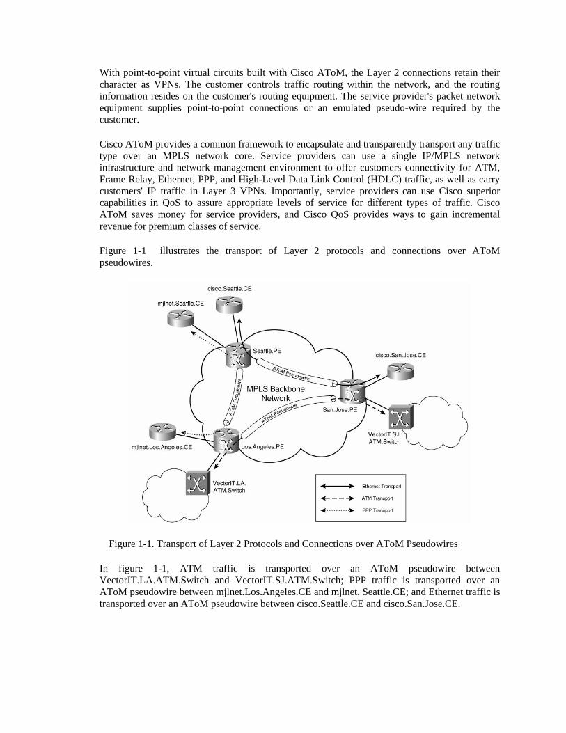
Figure 1-1 illustrates the transport of Layer 2 protocols and connections over AToM pseudowires.
Figure 1-1. Transport of Layer 2 Protocols and Connections over AToM Pseudowires
In figure 1-1, ATM traffic is transported over an AToM pseudowire between VectorIT.LA.ATM.Switch and VectorIT.SJ.ATM.Switch; PPP traffic is transported over an AToM pseudowire between mjlnet.Los.Angeles.CE and mjlnet. Seattle.CE; and Ethernet traffic is transported over an AToM pseudowire between cisco.Seattle.CE and cisco.San.Jose.CE.
2. Benefits of Any Transport over MPLS
Knowing that AToM pseudowires do a similar job to L2TPv3 pseudowires, you will not be surprised to learn that AToM-based L2VPNs share many advantages and disadvantages with L2TPv3-based L2VPNs.
Some of the main advantages for service providers implementing AToM-based L2VPNs are as follows:
• AToM-based L2VPNs are MPLS based, and are therefore deployed over an MPLS backbone network. It is possible to implement AToM over a Generic Routing Encapsulation (GRE) tunnel (and an IP backbone), but this is not a typical method of implementation.
• AToM allows the consolidation of service provider legacy and MPLS backbone networks. This consolidation of legacy and MPLS networks allows the service provider to save on operational and capital expenditure, while maintaining revenues for both legacy and IP/MPLS services.
• Service providers can use AToM to deploy both legacy Layer 2 (Frame Relay and so on) and newer Ethernet service offerings.
• Because AToM is MPLS based, a service provider can provision high service availability and traffic protection for AToM-based L2VPNs using MPLS traffic engineering (MPLS-TE) and MPLS-TE fast-reroute.
Some of the main advantages of AToM-based L2VPNs for enterprises are as follows:
• AToM-based L2VPNs can be used to transport non-IP protocols such as Internetwork Packet Exchange (IPX) between enterprise sites.
• Enterprises can maintain complete control of their routing when using AToM-based L2VPNsProvider Edge (PE) routers do not participate in enterprise routing (unlike with MPLS Layer 3 VPNs).
• MPLS-based pseudowires can be used to provision both Virtual Private Wire Service (VPWS) and Virtual Private LAN Service (VPLS) architectures. Note, however, that although Label Distribution Protocol (LDP)-signaled MPLS pseudowires are used in both VPWS and VPLS architectures, the AToM command syntax described in this chapter is used for VPWS.
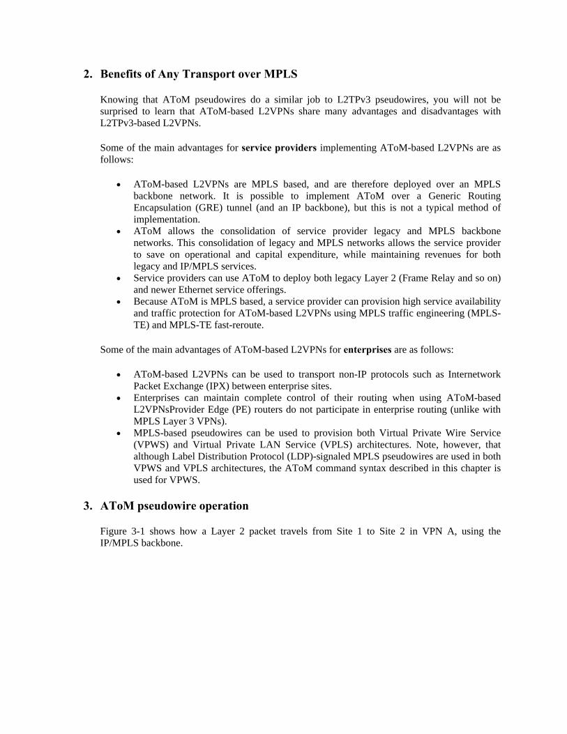
3. AToM pseudowire operation Figure 3-1 shows how a Layer 2 packet travels from Site 1 to Site 2 in VPN A, using the IP/MPLS backbone.
• The following process shows a Layer 2 packet traveling from Customer Edge 1 (CE1) on VPN A (Site 1) across the service-provider network, to CE 2 on VPN A (Site 2).
CE1 connects to the Provider Edge 1 (PE1) on the service-provider network through a traditional Layer 2 virtual circuit, such as a Frame Relay, data link connection identifier (DLCI 101), virtual circuit. The packet travels from CE1 to PE1 through that circuit.
• In the service provider network, an operator configures a label switched path (LSP) from PE1 to PE2
• For AToM, the operator configures
– (At PE1, a cross-connect between Attachment VC 101 and Emulated VC1, and the destination PE to be PE2
– (b) At PE2, a cross-connect between Emulated VC1 and Attachment VC 201, and the source PE to be PE1
– Note: No AToM configuration is required on the P routers.
• At PE1, the following events take place on the ingress interface of the router:
– An incoming packet on the ingress line card of the provider-edge router is stripped of the Layer 2 header.
– A control word and virtual-circuit label [10] are pushed on the packet.
– An appropriate network-facing interface is selected.
– A tunnel label is pushed (for normal MPLS routing through the cloud).
The control word and the virtual-circuit label are pertinent only to the ingress and egress provider-edge routers. The routers within the MPLS backbone (the P routers) do not use the control word or the virtual-circuit label. Instead, the P routers use the tunnel label [50 & 90] to move the packet through the MPLS backbone. A P router does not distinguish AToM traffic from other types of traffic. The packet is handled just like other packets in the MPLS backbone.
• The packet is sent through the service-provider network to PE2. • The following events take place on the egress router PE2:
– The virtual-circuit label [10] is stripped.
– The control word is processed and stripped.
– The header is reconstructed.
– The packet is sent out the appropriate customer-facing interface.
No tunnel label is present in the network-facing side of the router because that label was popped by the penultimate router.
• PE2 connects to CE2 through a traditional Layer 2 virtual circuit, such as Frame Relay (DLCI 102) virtual circuit.
AToM Data Channel Packet Forwarding
The packet format consists of the following:
• One or more tunnel labels These tunnel labels can be advertised between adjacent PE and P routers (LSRs) using LDP, TDP, or RSVP-TE. Note, however, that the use of the Cisco-proprietary Tag Distribution Protocol (TDP) is now deprecated in MPLS networks.
• A PW label This is also referred to as the VC label and serves as a demultiplexor that ensures that data channel packets are correctly associated with an attachment circuit.
The PW label serves the same purpose as the session header (session ID and optional cookie) does with L2TPv3 pseudowires.
• An optional control word This performs the same function as the service-specific sublayer with L2TPv3 pseudowires.
The PW label and the presence (or otherwise) of a control word are advertised in LDP Label Mapping messages exchanged during pseudowire setup.
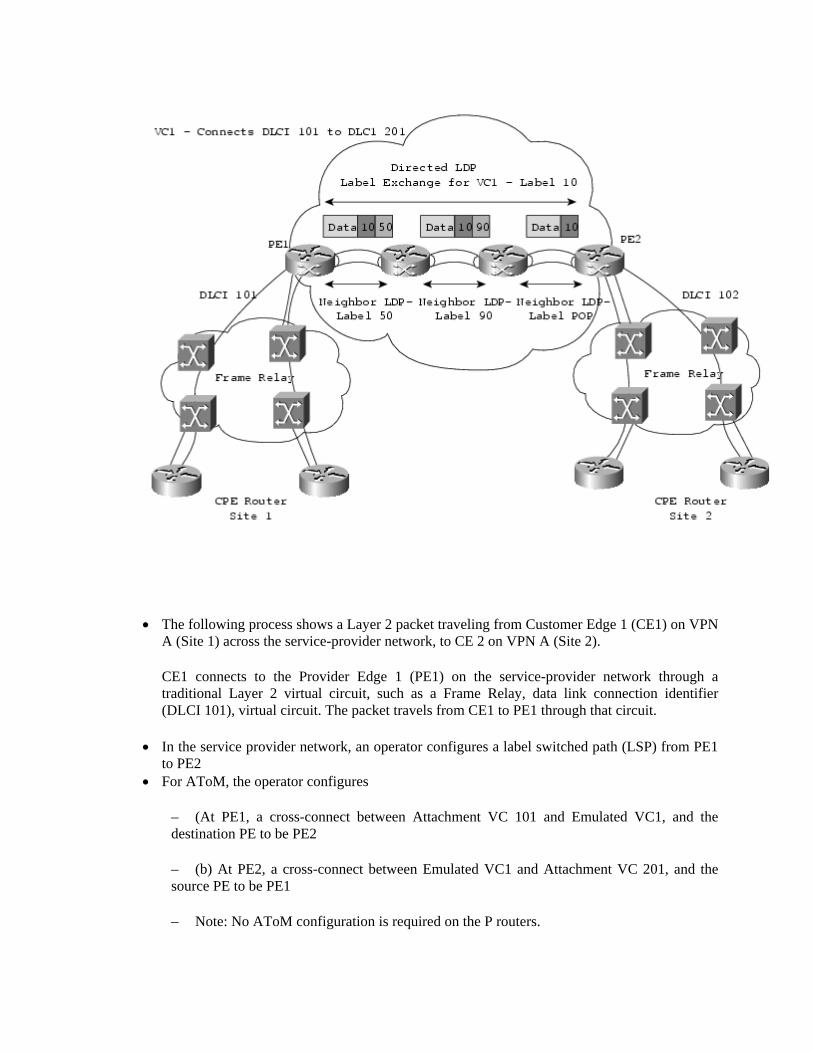
Figure 3-2 depicts the transmission of AToM data channel packets.
Figure 3-2 Transmission of AToM Data Channel Packets
Figure 3-2 shows the transport of a AToM data channel packet across the MPLS backbone network between Los.Angeles.PE to San.Jose.PE (see the lower half of the figure), but it also shows how control channel packets (see the upper half of the figure) influence the form of data channel packets.
If you take a close look at figure 3-2, you can see that the following events occur:
Step 1. San.Jose.PE advertises a (tunnel) label (3 [implicit-null]) corresponding to its IP address (10.1.1.2) to Los.Angeles.P using LDP.
Similarly, Los.Angeles.P advertises a (tunnel) label (200) corresponding to San.Jose.PE's IP address (10.1.1.2) to Los.Angeles.PE.
Step 2. San.Jose.PE sends an LDP Label Mapping message to Los.Angeles.PE. This message includes an FEC TLV and a Generic Label TLV. The FEC TLV includes a PW ID FEC element, with the C bit set to 1, the PW Type specified as High-Level Data Link Control (HDLC), the PW (VC) ID set to 1001, and the Interface Parameters, which specify an attachment circuit MTU of 1500. The Generic Label TLV specifies a label value of 100 (this is the PW label). Although not explicitly shown in Figure 3-2, Los.Angeles.PE also sends an LDP Label Mapping message to San.Jose.PE, and the pseudowire has been established.
Step 3. Los.Angeles.PE now receives an HDLC frame on the attachment circuit connected to mjlnet.Los.Angeles.CE.
Step 4. Los.Angeles.PE encapsulates the HDLC with a control word (this is included because the C bit was set to 1 in the PW ID FEC element in the LDP Label Mapping message in step 2), a PW (VC) label (100, which was included in the Generic Label FEC in the LDP Label Mapping message sent in step 2), and a tunnel label (200, which was received from Los.Angeles.P in step 1). The purpose of the tunnel label is to transport the encapsulated frame to the egress PE router, which in this case is San.Jose.PE. Los.Angeles.PE then sends the encapsulated HDLC frame to Los.Angeles.P. Note that by default a control word is not required with an HDLC pseudowire. A control word is required only if sequencing is configured. Configuration of sequencing is discussed later in this chapter.
Step 5. Los.Angeles.P pops the tunnel label because the outgoing label (3, implicit-null)
indicates that the egress PE router is the next hop (so, Los.Angeles.P performs a penultimate hop pop [PHP]). Los.Angeles.P now forwards the encapsulated HDLC frame to San.Jose.PE.
Step 6. San.Jose.PE receives the encapsulated HDLC frame, and removes the PW (VC) label and the control word. The PW (VC) label indicates the local attachment circuit on which the encapsulated HDLC frame should be forwarded, and so San.Jose.PE then sends the HDLC frame to mjlnet.San.Jose.CE.
That is AToM data channel packet forwarding from Los.Angeles.PE to San.Jose.PE. Data channel packet forwarding from San.Jose.PE to Los.Angeles.PE happens in exactly the same manner, just in the opposite direction.
MPLS Improves Scalability in Circuit-Based Networks
Most service providers have implemented connection-oriented ATM networks in the core. ATM provides performance, bandwidth, and the ability to perform traffic engineering. However, an ATM network does not scale well, because it relies on virtual circuit state information in the core.
In contrast MPLS AToM scales well and does not require VC state information to be maintained by core MPLS devices. This is accomplished by label stacking to direct multiple connections bound for the same destination onto a single. Using MPLS, the provider must configure only the edge device (provider edge) router, as opposed to all the P routers in the network.
AToM Helps Transition to IP/MPLS Networks
As service providers migrate to IP/MPLS networks, they need to be able to support existing services, such as the ability to transport Layer 2 packets. Using AToM, the service provider can transport Layer 2 packets over the IP/MPLS backbone. AToM is the architectural framework of transporting different Layer 2 packets, such as ATM, Frame Relay, Ethernet, PPP, and HDLC, over an MPLS backbone. In a nutshell, AToM encapsulates the packets at the provider-edge router and then transports them over the backbone. When the packets reach the provider-edge router on the other side of the backbone, they are unencapsulated and sent to their destination.
The upgrade to AToM is transparent to the customers, because the service provider's backbone network is separate from the customer's network. The service provider does not participate in the customer's Layer 3 routing. The service provider provides Layer 2 connectivity only.
4. Advanced AToM
Protecting AToM Pseudowires with MPLS Traffic Engineering Fast Reroute
MPLS traffic engineering automatically establishes and maintains LSPs across the MPLS core network using RSVP. Such LSPs are created based on the resource constraints that are configured and available network resources, such as bandwidth. IGP routing protocols such as IS-IS or OSPF announce available network resources using traffic engineering protocol extensions along with link state advertisements throughout the network.
In any network, links, routers, or both can fail because of unexpected events. Network operators include this factor their network planning by having redundant links and routers at the physical or logical locations where the failures are most likely to happen. When such failure conditions occur, routers within the network might temporarily have inconsistent routing information. They might need to exchange routing updates and come up with a new, consistent view of the network. This process is known as network convergence. During network convergence, routing loops and black holes can cause packet loss. The longer the convergence takes, the larger the amount of packet loss.
The convergence time includes the amount of time for an adjacent router to detect the link (or router) failure. It also includes the amount of time for this router to distribute the information to all other routers and for all other routers to recalculate routes in the forwarding tables. Detecting a link failure requires physical and link layerspecific mechanisms. MPLS traffic engineering does not have a way to reduce the amount of time to detect failures. However, it can reduce the time required to distribute the failure information and update the forwarding tables by using MPLS traffic engineering fast rerouting capability.
Prior to a failure, fast reroute calculates and establishes a protection traffic engineering tunnel around the link or node that is deemed vulnerable. Upon detecting such a failure, the backup tunnel takes over packet forwarding immediately. Rerouting typically takes less than 50 ms upon failure detection, and packet loss is kept minimal.
Before you enable fast reroute for an AToM pseudowire, you need to configure an MPLS traffic engineering tunnel as the preferred path, as shown in the previous case study. Then at the ingress PE where the traffic engineering tunnel headend is, you can use fast reroute options to configure a backup traffic engineering tunnel to protect the primary traffic engineering tunnel.
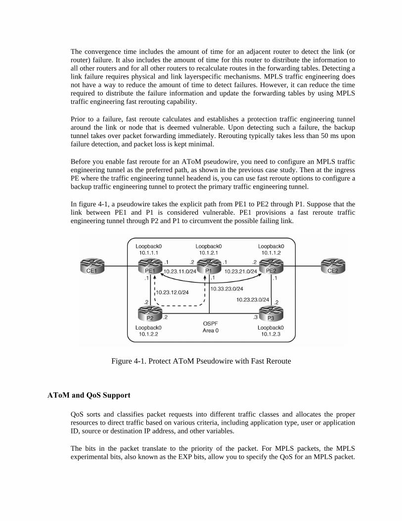
In figure 4-1, a pseudowire takes the explicit path from PE1 to PE2 through P1. Suppose that the link between PE1 and P1 is considered vulnerable. PE1 provisions a fast reroute traffic engineering tunnel through P2 and P1 to circumvent the possible failing link.
Figure 4-1. Protect AToM Pseudowire with Fast Reroute
AToM and QoS Support
QoS sorts and classifies packet requests into different traffic classes and allocates the proper resources to direct traffic based on various criteria, including application type, user or application ID, source or destination IP address, and other variables.
The bits in the packet translate to the priority of the packet. For MPLS packets, the MPLS experimental bits, also known as the EXP bits, allow you to specify the QoS for an MPLS packet.
For an IP packet, the IP Precedence/differentiated services code point (DSCP) bits allow you to specify the QoS for an IP packet.
When an IP packet travels from one site to another, the IP Precedence field (the first three bits of the DSCP field in the header of an IP packet) specifies the QoS. Based on the IP Precedence marking, the packet is given the desired treatment such as the latency or the percent of bandwidth allowed for that class of service. If the service-provider network is an MPLS network, then the IP Precedence bits are copied into the MPLS EXP field at the edge of the network.
When an Ethernet frame travels from one site to another, the 802.1P field (three bits in the Ethernet header) specifies the QoS. Similarly for Frame Relay, the discard-eligible bit specifies the discard eligibility of the Frame Relay frame and for ATM, the cell loss priority (CLP) field specifies the cell loss priority of the cell being carried. This marking can be translated to the MPLS EXP field for preservation and transportation of QoS across the provider network.
If the service provider wants to set the QoS of an MPLS packet to a different value than that of the IP Precedence bits or the Layer 2 frame bits, the service provider can set the MPLS EXP field instead of overwriting the value in the customer's IP Precedence field or the Layer 2 header. The IP header or the Layer 2 frame remains available for the customer's use and is not changed as the packet travels through the MPLS network.
Service providers can classify MPLS packets according to their type, input interface, and other factors by setting (marking) each packet within the MPLS EXP field without changing the IP Precedence/DSCP/Layer 2 field. For example, service providers can classify packets with or without considering the rate of the packets that PE1 receives. If the rate is a consideration, the service provider marks in-rate packets differently from out-of-rate packets.
This setup allows service providers to offer different grades of service for the same transport type to different customers.
5. Configuration Examples for AToM by NS2: Coming soon.
Reference [1] Wei Luo, Carlos Pignataro, Dmitry Bokotey, Anthony Chan, “Layer 2 VPN Architectures”, Cisco Press 2005
[2] Luc De Ghein, “MPLS Fundamentals”, Cisco Press 2007. [3] Mark Lewis, “Comparing, Designing, and Deploying VPNs”, Cisco Press 2006. [4] Lancy Lobo, Umesh Lakshman, “MPLS Configuration on Cisco IOS Software”, Cisco Press 2005. [5] RFC 4385, “Pseudowire Emulation Edge-to-Edge (PWE3) Control Word for Use over an MPLS PSN”
[6] RFC 3985, “Pseudo Wire Emulation Edge-to-Edge (PWE3) Architecture”

[7] Website: http://pwp.netcabo.pt/amsoares/dynamips/dynamips.htm
[8] Website: http://dynagen.org/tutorial.htm
[9] Forum: http://vnpro.org/forum/index.php
TRAN CONG HUNG was born in VietNam in 1961
He received the B.E in electronic and Telecommunication engineering with first class honors from HOCHIMINH university of technology in VietNam, 1987.
He received the B.E in informatics and computer engineering from HOCHIMINH university of technology in VietNam, 1995.
He received the master of engineering degree in telecommunications engineering course from postgraduate department HaNoi university of technology in VietNam, 1998.
He received Ph.D at HaNoi university of technology in VietNam, 2004.
His main research areas are B – ISDN performance parameters and measuring methods, QoS in high speed networks, MPLS.
Currently, he is a lecturer, Dean of Faculty of Information Technology II in Posts and Telecoms Institute of Technology (PTIT), in HOCHIMINH City, VietNam.
TRẦN THỊ THÙY MAI was born in VietNam in 1987
She is fourth year student and will receive the B.E in Information Technology from Post and Telecommunication Institute of Technology (PTIT), campus in Hochiminh City, Vietnam, 2010 with graduation thesis entitled “Research Any Transport over MPLS”. Her main fields are MPLS, IP and TCP/IP Protocol.


![1 TM8106 Optical Networking Multi-Protocol Label Switching-Transport Profile (MPLS-TP) By Ameen Chilwan Syllabus: [1] MPLS Transport Profile (MPLS-TP):](https://img.pdfslide.us/doc/110x75/56649c9d5503460f9495c9d2/1-tm8106-optical-networking-multi-protocol-label-switching-transport-profile.jpg)