Embed Size (px)
Citation preview

A Study of Severe Multipath Errors for the Proposed GBAS Airport Surface Movement
Application
Young Shin Park, Sam Pullen, and Per Enge, Stanford University BIOGRAPHY Young Shin Park is a Ph.D. Candidate in Aeronautics and Astronautics in the Global Positioning System (GPS) Research Laboratory at Stanford University and a Senior Engineer at Qualcomm Incorporated. Her current research interests are enabling GBAS DCPS and airport surface movement, multipath model enhancement for the airport surface-movement environment, and indoor navigation. She received a MS from Stanford University and a BS from Seoul National University in Korea. Dr. Sam Pullen is a Senior Research Engineer at Stanford University, where he is the manager of the Local Area Augmentation System (LAAS) research effort. His current work includes the development of revised system architectures and algorithms for the next phase of LAAS to support Category II and III precision landings. Dr. Per Enge is a Professor of Aeronautics and Astronautics at Stanford University, where he is the Kleiner-Perkins, Mayfield, Sequoia Capital Professor in the School of Engineering. He directs the GPS Research Laboratory at Stanford.
ABSTRACT Ground Based Augmentation Systems (GBAS), such as the U.S. Local Area Augmentation System (LAAS) can be used for both precision approach and Differentially Corrected Positioning Service (DCPS) applications. Through its support of DCPS, the LAAS Ground Facility (LGF) is required to meet the integrity requirements of all other operations that could use the GBAS VHF Data Broadcast (VDB). Our previous work [1,2,3] demonstrated that the existing DCPS integrity requirements cannot be met by CAT I GBAS without changes to both the definition of DCPS integrity [4,5] and the airborne receiver requirements [6]. One of the implications is that some future applications of GBAS that planned to use DCPS, such as airport surface movement, cannot be supported by DCPS with the CAT-I
GBAS architecture. However, if airport surface movement is defined as a separate operation, it could be supported by the existing LGF geometry screening that mitigates the anomalous ionospheric threat for CAT-I precision approach and by designing Horizontal Protection Level (HPL) with increased σmultipath (or σpr_air) in airborne equipment to bound the higher multipath errors expected in the airport surface environment (as opposed to an aircraft in flight). Our previous work [7] confirmed this hypothesis and concluded that two or more times σpr_air allows to meet the current integrity requirements and achieve the Maximum Acceptable Error (MAE) of 10 meters with more than 99% availability. Note that this conclusion is derived under the assumption of no nominal error contribution to Horizontal Position Error (HPE) other than worst-case ionospheric errors. However, in the surface-movement environment, worst-case airborne multipath might be a significant fraction of HPE. Limited data for airport surface movement exists at present, so examining multipath models for ground and obstruction-influenced specular is the first step in exploring this further and is the subject of this paper. To cover higher multipath errors in the surface movement, Jahn’s multipath model for urban and suburban environments are used. If LGF geometry screening and new σmultipath using Jahn’s multipath model for optimistic suburban environment itself cannot support airport surface movement, the results in this paper include additional aircraft geometry screening proposed in [2,7] to meet the requirements and lower the MAE to a beneficial level while maintaining useful availability.
1.0 INTRODUCTION Ground Based Augmentation Systems (GBAS), such as the Local Area Augmentation System (LAAS) is primarily focused on supporting precision approach but can also be used for a variety of other applications that are known as Differentially Corrected Positioning Service (DCPS) applications. A typical GBAS-equipped airport is illustrated in Fig. 1. There are four reference receivers around the LAAS Ground Facility (LGF), which does the

central processing and determination of corrections that are transmitted via the VHF Data Broadcast (VDB) antenna. CAT-I precision approach availability is typically evaluated at 6 kilometers away from the centroid of the LGF reference receivers, which represents the maximum separation of the CAT-I Decision Height (DH) for most airports [8]. Ten nautical miles (18.5 kilometers) farther out along this approach direction marks the boundary of the Precision Approach Region (PAR). DCPS is broadly composed of (but is not limited to) three operations. The first operation is terminal-area navigation for the aircraft in the region from the PAR to 45 kilometers away from the LGF. The second operation is enroute navigation for aircraft passing over the airport that can receive and make use of the GBAS VDB. The third operation is airport surface movement for aircraft on airport taxiways (and thus quite close to the LGF centroid). Note that the VDB is required to provide coverage out to 45 kilometers assuming a 3-degree glideslope for precision approaches. At higher altitudes, aircraft will receive the VDB at significantly further distances. Through its support of DCPS, the LGF is required to meet the integrity requirements of all other operations that could use the GBAS VDB. CAT-I precision approach is approved under anomalous ionospheric conditions (the
most constraining threat) for at least a 6-kilometer separation. The current GABS requirements for DCPS integrity are that position errors should be bounded by the corresponding protection levels to the 10-7-per-hour probability level, regardless of the size of the error [4,5]. Our first paper regarding DCPS [1] showed that the existing DCPS integrity requirements cannot be met by CAT I GBAS without changes to both the definition of DCPS integrity [4,5] and the airborne receiver requirements [6] under anomalous ionospheric threat. Our second paper [2] identifies the changes that are required and recommends specific sets of alternatives. One of its conclusions is that some future applications of GBAS that planned to use DCPS, such as airport surface movement, cannot be supported by DCPS with the CAT-I GBAS architecture. It suggests one important further change to the LAAS avionics requirements. The current GBAS MOPS forbids use of the GBAS Position/Velocity/Timing (PVT) outputs if DCPS is not enabled by the LGF [6]. As [2] points out, it will not support all applications that can make use of the PVT outputs, even if DCPS is enabled. Therefore, the PVT outputs should be “de-linked” from DCPS so that they can be used independently. PVT applications that cannot be supported by DCPS should be defined as separate applications of GBAS in the same manner as precision approach.
Figure 1. Operations included in DCPS at a GBAS-equipped airport.
Anomalous Ionosphere
Enroute Navigation
Terminal-Area Navigation
VDB
LAAS Reference Receivers
Nominal Ionosphere
6 km 18.5 km //
Runway
GBAS-equipped Airport
Surface Movement
Precision Approach Region
LAAS Ground Facility
Separation = 45 km

Our hypothesis was that, if airport surface movement is defined as a separate operation, it would be supported by the existing LGF geometry screening that mitigates the anomalous ionospheric threat for CAT-I precision approach and by designing Horizontal Protection Level (HPL) with increased σmultipath (or σpr_air) in airborne equipment to bound the higher multipath errors expected in the airport surface environment (as opposed to an aircraft in flight). Our previous work [7] confirmed this hypothesis and concluded that two or more times σpr_air allows to meet the current integrity requirements and achieve the Maximum Acceptable Error (MAE) of 10 meters with more than 99% availability. Note that this conclusion is derived under the assumption of no nominal error contribution to Horizontal Position Error (HPE) other than worst-case ionospheric errors. However, in the surface-movement environment, worst-case airborne multipath might be a significant fraction of HPE. Limited data for airport surface movement exists at present, so examining multipath models for ground and obstruction-influenced specular is the first step in exploring this further and is the subject of this paper. Because, for certain scenarios, LGF geometry screening and new σmultipath using Jahn’s multipath model for optimistic suburban environment is not sufficient by itself, the results in this paper include additional aircraft geometry screening (as proposed in [2,7]) to meet the requirements and lower the Maximum Acceptable Error (MAE). Since it is not clear what level of MAE corresponds to a given airport-surface operation, our goal is to minimize the achievable MAE (and thus Horizontal Alert Limit, or HAL) while maintaining useful availability.
2.0 MULTIPATH MODEL Since an aircraft in airport surface movement is on the ground, it suffers from higher multipath errors than while in flight, as additional signal reflections come from the ground, other aircraft or vehicles, and nearby buildings. The multipath errors applied to generate Horizontal Position Errors (HPEs) in this paper are based on Jahn’s multipath model [9] as used by the US/EU GNSS Working Group C (WG-C) [10]. Jahn et al. [9] illustrates the characteristics of satellite propagation channels for spread spectrum communications in detail. It gives a wideband channel model for land mobile satellite (LMS) services which characterizes the time-varying transmission channel between a satellite and a mobile user terminal. It is based on measurement campaigns at L-band. The parameters of the model are the results of fitting procedures to measured data. The parameters are shown in tables in [9] for various environments and elevation angles. The implementation
of Jahn’s method in the urban and suburban environments for a ground user is shown in detail in [10]. The approach for developing multipath models is briefly explained here. Jahn’s method is used to generate the amplitudes, phases and delays of the direct and multipath signals for urban and suburban environments. The discriminator function (S-curve) for a non-coherent discriminator (e.g., dot-product) is employed to determine the zero crossings with and without multipath [11]. Then, multipath error in meters is obtained by multiplying the difference of zero crossings with and without multipath in chips with chip width in meters [10]. RMS multipath errors (in terms of 1-σ) are displayed in Fig. 2. The red line in Fig. 2 shows the urban multipath curve generated by Jahn’s method for BOC(1,1) signal. Several papers published that BOC(1,1) signal and current L1 signal produces the similar multipath errors in the urban and suburban environments. The data generated by Jahn’s method using 2000 runs for the signal are used to obtain the fitted functions. Its formula is taken from [10] and is as follows.
))),075.29(deg)(1725.0(tan5782.33784.6max()( 1 εσ −⋅−= − Em 4101 −×=ε (1) The formula of the fitted function for the suburban multipath curve is also brought from [10] and is:
)(deg)),23566.0exp((254.3055349.0max()( εσ Em −⋅+= . (2)
Figure 2. Multipath models generated by Jahn’s method.
Note that these curves represent unsmoothed errors. In order to take advantage of 100-second smoothing effect, it is usually decreased by the factor of 10 for time-uncorrelated errors. Since multipath is time-correlated, decreases by a factor of 3 for the conservative model and
RM
S M
ultip
ath
Err
or (1
-σ, m
)
Elevation angel (deg)
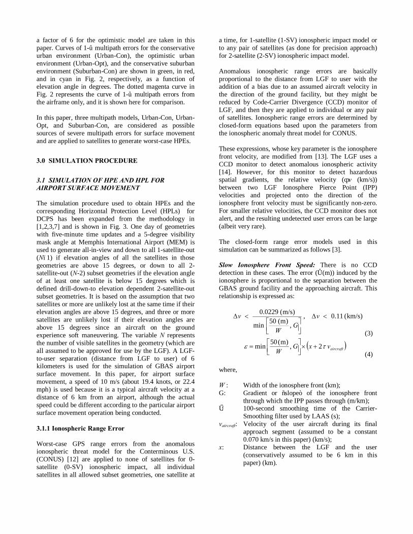
a factor of 6 for the optimistic model are taken in this paper. Curves of 1-σ multipath errors for the conservative urban environment (Urban-Con), the optimistic urban environment (Urban-Opt), and the conservative suburban environment (Suburban-Con) are shown in green, in red, and in cyan in Fig. 2, respectively, as a function of elevation angle in degrees. The dotted magenta curve in Fig. 2 represents the curve of 1-σ multipath errors from the airframe only, and it is shown here for comparison. In this paper, three multipath models, Urban-Con, Urban-Opt, and Suburban-Con, are considered as possible sources of severe multipath errors for surface movement and are applied to satellites to generate worst-case HPEs.
3.0 SIMULATION PROCEDURE
3.1 SIMULATION OF HPE AND HPL FOR AIRPORT SURFACE MOVEMENT The simulation procedure used to obtain HPEs and the corresponding Horizontal Protection Level (HPLs) for DCPS has been expanded from the methodology in [1,2,3,7] and is shown in Fig. 3. One day of geometries with five-minute time updates and a 5-degree visibility mask angle at Memphis International Airport (MEM) is used to generate all-in-view and down to all 1-satellite-out (N–1) if elevation angles of all the satellites in those geometries are above 15 degrees, or down to all 2-satellite-out (N-2) subset geometries if the elevation angle of at least one satellite is below 15 degrees which is defined drill-down-to elevation dependent 2-satellite-out subset geometries. It is based on the assumption that two satellites or more are unlikely lost at the same time if their elevation angles are above 15 degrees, and three or more satellites are unlikely lost if their elevation angles are above 15 degrees since an aircraft on the ground experience soft maneuvering. The variable N represents the number of visible satellites in the geometry (which are all assumed to be approved for use by the LGF). A LGF-to-user separation (distance from LGF to user) of 6 kilometers is used for the simulation of GBAS airport surface movement. In this paper, for airport surface movement, a speed of 10 m/s (about 19.4 knots, or 22.4 mph) is used because it is a typical aircraft velocity at a distance of 6 km from an airport, although the actual speed could be different according to the particular airport surface movement operation being conducted. 3.1.1 Ionospheric Range Error Worst-case GPS range errors from the anomalous ionospheric threat model for the Conterminous U.S. (CONUS) [12] are applied to none of satellites for 0-satellite (0-SV) ionospheric impact, all individual satellites in all allowed subset geometries, one satellite at
a time, for 1-satellite (1-SV) ionospheric impact model or to any pair of satellites (as done for precision approach) for 2-satellite (2-SV) ionospheric impact model. Anomalous ionospheric range errors are basically proportional to the distance from LGF to user with the addition of a bias due to an assumed aircraft velocity in the direction of the ground facility, but they might be reduced by Code-Carrier Divergence (CCD) monitor of LGF, and then they are applied to individual or any pair of satellites. Ionospheric range errors are determined by closed-form equations based upon the parameters from the ionospheric anomaly threat model for CONUS. These expressions, whose key parameter is the ionosphere front velocity, are modified from [13]. The LGF uses a CCD monitor to detect anomalous ionospheric activity [14]. However, for this monitor to detect hazardous spatial gradients, the relative velocity (Δv (km/s)) between two LGF Ionosphere Pierce Point (IPP) velocities and projected onto the direction of the ionosphere front velocity must be significantly non-zero. For smaller relative velocities, the CCD monitor does not alert, and the resulting undetected user errors can be large (albeit very rare). The closed-form range error models used in this simulation can be summarized as follows [3]. Slow Ionosphere Front Speed: There is no CCD detection in these cases. The error (ε (m)) induced by the ionosphere is proportional to the separation between the GBAS ground facility and the approaching aircraft. This relationship is expressed as:
)km/s(11.0,,)m(50min
)m/s(0229.0<∆
<∆ vG
W
v
(3)
( )aircraftvxGW
τε 2,)m(50min +×
=
(4)
where, W : Width of the ionosphere front (km); G: Gradient or “slope” of the ionosphere front
through which the IPP passes through (m/km); τ: 100-second smoothing time of the Carrier-
Smoothing filter used by LAAS (s); vaircraft: Velocity of the user aircraft during its final
approach segment (assumed to be a constant 0.070 km/s in this paper) (km/s);
x: Distance between the LGF and the user (conservatively assumed to be 6 km in this paper) (km).

Moderate Ionosphere Front Speed: In these cases, the CCD monitor alerts for some conditions within this range of relative speeds. Consequently, the errors that users could suffer begin to decrease. Under the CONUS threat model, the maximum differential range error the user would suffer is no greater than 4 meters.
)km/s(11.0,)m(50min
)m/s(0229.0<∆<
vG
W (5) Fast Ionosphere Front Speed: In these cases, The CCD monitor alerts with a very small missed-detection probability. Under the CONUS threat model, the maximum range error that users could potentially suffer is no greater than 2.5 meters. )km/s(11.0>∆ v (6) The applied ionospheric range errors are all positive as expressed before and are actually magnitude of actual errors. This is not a problem for 0-SV or 1-SV impact model, but it may miss the worst-case error for the 2-SV impact model. To take care of it, three possible combinations of range errors of satellites k1 and k2 are considered as below. The factor 0.5 (instead of 1) is chosen to release over-conservatism of maximum ionosphere induced horizontal error for the worst-case ionospheric front affecting two satellites because a single front must have the “polarity,” or direction of ionospheric delay change, for both satellites. It (instead of 0.2) is also selected to bound the “two-front” event observed on November 20th in 2003. IEHk1,k2,1 = |Shorizontal,k1 εk1,positive + Shorizontal,k2 εk2,positive| (7) IEHk1,k2,2 = |Shorizontal,k1 εk1,positive + 0.5Shorizontal,k2 εk2,negative| (8) IEHk1,k2,3 = |0.5Shorizontal,k1 εk1,positive + Shorizontal,k2 εk2,negative| (9) where Shorizontal ε is root-sum-square (RSS) of Shorizontal,1 ε and Shorizontal,2 ε. Here, Shorizontal,1 and Shorizontal,2 are the rows of the weighted-least-squares projection matrix corresponding to the horizontal position component [6]. The largest of these three vertical errors is the worst-case ionosphere-induced-Error-in-Horizontal (IEH).
3.1.2 Multipath Error In addition to anomalous ionospheric errors, randomly severe multipath errors are generated using Monte Carlo simulation with normal distributions with a mean of zero and variances of three multipath models, Urban-Con, Urban-Opt, and Suburban-Con multipath models described in section 2.0 and are applied to all satellites in all allowed subset geometries. The 30 trials are made for Monte Carlo simulation and it is chosen by a compromise between the simplicity and the accuracy of surface-movement simulation based on the saturation of randomness. 3.1.3 HPL – Standard Deviations and Parameters The nominal ionospheric gradient parameter, the standard deviation of the vertical ionosphere gradient or σvig, may vary due to the LGF geometry screening needed to protect CAT-I precision approach, which is briefly described in the next section. Here, the nominal (uninflated) σvig of 6.4 millimeters per kilometer is used to compute both HPE and the uninflated HPL, and a specific value of inflated σvig for each epoch obtained by the real-time sigma-inflation algorithm used for precision approach is used to compute the HPL. The standard deviation of the aircraft contribution to the total pseudorange error, σpr_air, includes airborne receiver noise and a standard allowance for airframe multipath. The performance of the airborne subsystem is defined in terms of Airborne Accuracy Designators (AAD). Currently two AAD (A and B) are defined in and empirical expressions can be obtained from [5,6]. In these simulations, the more conservative model (AAD A) is used for computing errors and uninflated HPL, while AAD B is used for computing inflated HPL at an aircraft. For both of them, the combination of Airframe Multipath Designator (AMD) A defines in [5,6] and Jahn’s multipath models in section 2.0 is used for the airborne σmultipath. A broadcast multiplier (unitless) for computation of the ephemeris error position bound for the GBAS positioning service, Kmd_e_POS_hrz, of 5.085, and an ephemeris decorrelation parameter, or “P-value” (Pk), of 0.00018 meters per meter, are used [6,15]. HPE and HPL are computed as described in [6,15], and the largest HPE and corresponding HPL are stored for each subset geometry generated by the satellite geometry simulation described above.

Figure 3. Airport surface movement simulation procedure to generate worst-case errors under ionospheric anomalies.
3.2 REAL-TIME σvig-INFLATION SIMULATION FOR PRECISION APPROACH The simulation used to establish real-time inflation factors for σvig to protect CAT-I precision approach is based on the methodology in [8] and is modified to fit the current CAT-I GBAS operational design. Subset geometries are generated for CAT I in the same manner as for DCPS except that valid airborne geometries are limited to no more than two satellites fewer than the N satellites approved by the LGF (N–2). In addition, geometries whose inflated Vertical Protection Levels (VPLs) are above the CAT-I Vertical Alert Limit (VAL) of 10 meters are “screened out” (i.e., made unavailable for use in the simulation). The assumed distance from LGF to user at the 200-ft CAT-I decision height is set to be 6 kilometers [8].The worst-case ionospheric impact for precision approach must be evaluated over all independent pairs of satellites in each subset geometry. Ionosphere-induced range errors for CAT I are determined by closed-form equations based upon the parameters from the ionospheric anomaly threat model for CONUS as shown in sub-section 3.1.1.
The broadcast multiplier (unitless) for computation of the ephemeris error position bound for Category I precision approach, Kmd_e_CAT1, of 5.085, and the same Pk of 0.00018 m/m, are used to get Ionosphere-induced-Error-in-Vertical (IEV), VPL, and required inflation factors for σvig [8] as needed. Note that the multiplier (unitless) which determines the probability of missed detection, Kmd, of zero is used in IEV because IEV only includes the impact of ionospheric anomalies. The applied ionospheric range errors are all positive as expressed before and are actually magnitude of actual errors. To take care of it, three possible combinations of range errors of satellites k1 and k2 are considered as below. IEVk1,k2,1 = |Svertical,k1 εk1,positive + Svertical,k2 εk2,positive| (10) IEVk1,k2,2 = |Svertical,k1 εk1,positive + 0.5Svertical,k2 εk2,negative| (11) IEVk1,k2,3 = |0.5Svertical,k1 εk1,positive + Svertical,k2 εk2,negative| (12) where Svertical is the row of the weighted-least-squares projection matrix corresponding to the vertical position component [6]. The largest of these three vertical errors is the worst-case IEV. Fig. 4 shows the Maximum-Ionosphere-induced-Error-in-Vertical (MIEV) per epoch.
0-SV, 1-SV, 2-SV impact D = 6 km Vaircraft = 10 m/s
Vaircraft = 10 m/s, LGF real-time inflated σvig
σmultipath from Jahn Suburban-Con Multipath Model
Loop through all
independent individual satellites
Compute worst-case Horizontal Position Error (HPE)
Iono
. Slo
pe (m
m/k
m)
Elevation (degree)
15 65
375
425
Plot not precisely to scale
Generate all in view, all 1-SV out, all 2-SV out, …, down to all
elevation dependent 2-SV out subset geometries
Compute Corresponding Horizontal Protection Level (HPL)
CONUS CAT-I Ionospheric Anomaly
Threat Model [12]
Jahn’s Multipath Model - Urban-Con - Urban-Opt - Suburban-Con
Monte Carlo Sim. With N(0, σ2
multipah) and 30 trials.
- 1 day (24 hours) - 5-minute updates - 24-SV constellation (All SV’s healthy) - Memphis Int’l Airport

0 50 100 150 200 2500
5
10
15
20
25
30
35
40
MIEV per epochOCS limit
Figure 4. MIEV simulation results of all the subset geometries for precision approach at Memphis using RTCA 24-SV GPS constellation.
0 50 100 150 200 250
7
8
9
10
11
12
13
14
15
16
17
18
Figure 5. Real-time inflated σvig for precision approach at Memphis. In order to ensure that VAL bounds the MIEV for all usable “subset” geometries, real-time-sigma-inflation beyond the nominal sigma value of 6.4 mm/km is performed when needed using the pre-computed and stored values of IEV and VPL for CAT-I precision approach. This simulation procedure is based on Fig. 10 and Fig. 11 in [8]. A single epoch is considered as an example to briefly explain the concept of σvig inflation. If IEV for a particular subset geometry is above the tolerable error limit (28.78 m) derived from the Obstacle Clearance Surface (OCS) at the CAT-I decision height (DH) [16], σvig is increased until the VPL for that geometry (based upon the inflated σvig) is above VAL; thus that problematic geometry will be screened out (made unavailable) by the VPL check at the aircraft. This
sigma-inflation procedure is repeated until all subset geometries with IEV exceeding 28.78 m are made unusable, meaning that the “maximum IEV” (MIEV) of the remaining “usable” geometries is no greater than 28.78 m at the DH. The resulting value of σvig per each epoch, as shown in Fig. 5, is fed into the airport surface movement (or DCPS) simulation to compute inflated HPL for users not limited to the CAT-I approach phase of flight.
4.0 INTEGRITY ANALYSIS AND AVAILABILITY COMPUTAION Since the GBAS airport surface movement is currently one of the operations of DCPS, the GBAS integrity requirements for surface movement in this paper are borrowed from the current GBAS requirements for DCPS integrity. They are again that position errors should be bounded by the corresponding protection levels to the 10-
7-per-hour probability level. In other words, HPEs should be protected by their HPLs 100% in this context because the data used here are updated every 5 minutes and if a HPE of one epoch is not bounded by its HPL, then it is 0.083-per-hour probability which is much bigger than 10-
7-per-hour probability level and it fails to meet the requirements. Given worst-case HPE and HPL per drill-down-to elevation dependent 2-satellite-out subset geometry as a result of the simulation illustrated in section 3.0, two scenarios of integrity analysis is shown. One is the case that the integrity requirements is met and therefore no additional geometry is needed, and the other is the case that they aren’t and therefore it needs additional airborne geometry screening. All drill-down-to elevation dependent 2-satellite-out subset geometries are used for integrity analysis since all possible geometries should be considered for integrity analysis by its definition. Availability is calculated from a set of all-in-view geometries plus subset geometries with one satellite missing (these will be called “drill-down to one satellite out” geometries or “N-1 geometries” from now on) because this set is the geometries that the aircraft experiences in fact. Note that dots in this section representing subset geometries don’t necessarily express results of the simulation described in this paper. 4.1 NO ADDITIONAL GEOMETRY SCREENING Integrity Analysis Simulated HPEs which an aircraft would suffer from anomalous ionospheric residual errors and severe multipath errors, and the corresponding HPLs which it would calculate using real-time LGF σvig inflation and Suburban-Con multipath model for σmultipath, are shown in
6.4
Time index
Infla
ted
σ vig
(mm
/km
)
Time index
Use
ver
tical
pos
ition
err
or (m
)

Fig. 6. Note that HPE is unacceptably large for surface movement up to the order of 102 meters only because no advanced HAL-HPL check to screen out bad geometries is performed, since HAL is not specified in surface movement (or DCPS) yet. Along the black line, HPE is the same as HPL. In the upper triangle above this black line, HPE is bounded by HPL, while HPE is not bounded by HPL in the lower triangle below it. The blue dots represent geometries with acceptable errors when the allowed MAE is 20 meters. The green dots refer to geometries filtered by their HPLs, since the aircraft would screen out all the geometries whose HPL is greater than the MAE. The red dots denote significant geometries that might pose an anomalous ionospheric or multipath threat to surface movement, and surface movement integrity cannot be met under anomalous ionosphere and severe multipath unless these points are made unavailable by some other means. The scenario displayed in Fig. 6 does not have any significant geometries. In other words, It meets the surface-movement integrity requirements for an MAE of 20 meters. Therefore, no additional geometry screening is required for this scenario.
Figure 6. Example scenario in which the proposed GBAS surface-movement integrity requirements are met. Availability Calculation Availability is obtained by counting how many geometries have HPLs less than or equal to screening limit which is the same as MAE (20 m) in this scenario among N−1 geometries. In Fig. 7, the red dots are unavailable.
Figure 7. Example scenario in which the proposed GBAS surface-movement integrity requirements are met (points counted for availability are shown).
4.2 ADDITIONAL AIRBORNE GEOMETRY SCREENING Integrity Analysis In this sub-section, the allowed MAE of 10 meters is selected to demonstrate the capabilities of additional airborne geometry screening. The same HPEs and HPLs as in Fig. 6 are shown in Fig. 8. By reducing the allowed MAE from 20 to 10 meters, the scenario has significant geometries shown as red dots in Fig. 8. Additional airborne geometry screening (as introduced in our previous work [2]) is needed to make these points unavailable and thus protect integrity. This method introduces a “screening HAL” that is lower than the normal HAL or MAE that is dictated by safety concerns. The required “screening HAL” is determined by the minimum HPL value among these significant geometries, which is 5.73 meters for this scenario (see Fig. 8). This lower limit on HPL ensures that, for this scenario, potentially threatening points are screened out by users.
HPL
(m)
HPE (m)
MAE = 20 m
HPL = 20 m
HPE (m)
HPL
(m)
HPL = 20 m
Screening Limit = 20 m
Unavailable

Figure 8. Example scenario in which the proposed GBAS surface-movement integrity requirements are met by lowering the screening limit. Availability Calculation Availability is determined by counting how many geometries have HPLs less than or equal to the screening limit, which is the same as screening HAL (5.73 m) in this scenario among N−1 geometries. In Fig. 9, the red dots are unavailable.
Figure 9. Example scenario in which the proposed GBAS surface-movement integrity requirements are met by lowering the screening limit (points counted for availability are shown).
5.0 RESULTS AND DISCUSSION The results in this paper are shown in terms of sensitivity of availability to the multipath model and the ionospheric threat impact model for several values of the MAE. Results for an MAE of 30 meters are shown in Fig. 10; for an MAE of 20 meters in Fig. 11; and for an MAE of 10 meters in Fig. 12. The multipath models considered are no multipath, suburban-conservative (Suburban-Con), urban-optimistic (Urban-Opt), and urban-conservative (Urban-Con) multipath models, and they are shown on the vertical axis. The 0-satellite (0-SV, no ionosphere), 1satellite (1-SV), and 2-satellites (2-SV) impact models of ionospheric threat are shown on the horizontal axis. The values in the figures represent the availabilities as percentages, while the values in the parentheses refer to the required screening limits in meters at the aircraft. A tendency is easily seen in figures that screening limits and the availabilities decrease as it goes to the right on the horizontal axis and up on the vertical axis, and the value of MAE decreases.
Mul
tipat
h M
odel
Urban-Con
99.92 (26.62)
99.59 (11.83)
99.47 (10.21)
> 99.9%
> 99.5%
Urban-Opt
99.96 (30)
99.92 (25.62)
99.92 (20.84)
> 99%
> 95%
Sub urban-
Con
99.96 (30)
99.96 (30)
99.92 (24.01)
> 90%
> 85%
No Multi-
path
99.96 (30)
99.96 (30)
99.92 (24.73)
> 75%
> 50%
0-SV Impact 1-SV Impact 2-SV Impact < 50%
Iono. Impact Model Figure 10. Sensitivity of availability to the multipath model and the ionospheric threat impact model for MAE = 30 m using 24-SV GPS constellation. As shown in Fig. 10, setting an MAE to 30 meters gives very high availabilities, more than 99% for the all the combinations of multipath models and ionospheric threat impact models. Most of the multipath models provide more than 99.9% except for the Urban-Con model. For example, ionospheric range error impacting on one satellite combined with Suburban-Con multipath provides 99.9% with no additional airborne geometry screening since the screening limit is 30 meters which is the same as
HPL
(m)
HPE (m)
HPL = 10 m
MAE = 10 m
HPE (m)
HPL
(m)
HPL = 10 m
Screening Limit = Screening HAL = 5.73 m
Unavailable
Screening HAL = 5.73 m
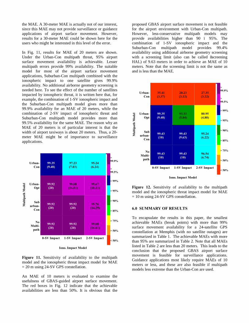
the MAE. A 30-meter MAE is actually not of our interest, since this MAE may not provide surveillance or guidance applications of airport surface movement. However, results for a 30-meter MAE could be shown here for the users who might be interested in this level of the error. In Fig. 11, results for MAE of 20 meters are shown. Under the Urban-Con multipath threat, 95% airport surface movement availability is achievable. Lesser multipath errors provide 99% availability. The suitable model for most of the airport surface movement applications, Suburban-Con multipath combined with the ionospheric impact to one satellite gives 99.9% availability. No additional airborne geometry screening is needed here. To see the effect of the number of satellites impacted by ionospheric threat, it is written here that, for example, the combination of 1-SV ionospheric impact and the Suburban-Con multipath model gives more than 99.9% availability for an MAE of 20 meters, while the combination of 2-SV impact of ionospheric threat and Suburban-Con multipath model provides more than 99.5% availability for the same MAE. The reason why an MAE of 20 meters is of particular interest is that the width of airport taxiways is about 20 meters. Thus, a 20-meter MAE might be of importance to surveillance applications.
Mul
tipat
h M
odel
Urban-Con
99.35 (9.48)
97.23 (7.03)
95.24 (6.24)
> 99.9%
> 99.5%
Urban-Opt
99.92 (20)
99.88 (16.81)
99.67 (10.21)
> 99%
> 95%
Sub urban-
Con
99.92 (20)
99.92 (20)
99.76 (14.29)
> 90%
> 85%
No Multi-
path
99.92 (20)
99.92 (20)
99.88 (16.81)
> 75%
> 50%
0-SV Impact 1-SV Impact 2-SV Impact < 50%
Iono. Impact Model Figure 11. Sensitivity of availability to the multipath model and the ionospheric threat impact model for MAE = 20 m using 24-SV GPS constellation. An MAE of 10 meters is evaluated to examine the usefulness of GBAS-guided airport surface movement. The red boxes in Fig. 12 indicate that the achievable availabilities are less than 50%. It is obvious that the
proposed GBAS airport surface movement is not feasible for the airport environment with Urban-Con multipath. However, less-conservative multipath models may provide availabilities higher than 90 – 95%. The combination of 1-SV ionospheric impact and the Suburban-Con multipath model provides 99.4% availability using additional airborne geometry screening with a screening limit (also can be called “screening HAL) of 9.63 meters in order to achieve an MAE of 10 meters. Note that the screening limit is not the same as and is less than the MAE.
Mul
tipat
h M
odel
Urban-Con
35.41 (3.37)
20.23 (3.12)
27.35 (3.22)
> 99.9%
> 99.5%
Urban-Opt
99.35 (9.48)
93.33 (5.84)
80.95 (4.80)
> 99%
> 95%
Sub urban-
Con
99.43 (10)
99.43 (9.63)
95.24 (6.22)
> 90%
> 85%
No Multi-
path
99.43 (10)
99.43 (10)
96.54 (6.74)
> 75%
> 50%
0-SV Impact 1-SV Impact 2-SV Impact
< 50%
Iono. Impact Model Figure 12. Sensitivity of availability to the multipath model and the ionospheric threat impact model for MAE = 10 m using 24-SV GPS constellation.
6.0 SUMMARY OF RESULTS To encapsulate the results in this paper, the smallest achievable MAEs (break points) with more than 99% surface movement availability for a 24-satellite GPS constellation at Memphis (with no satellite outages) are summarized in Table 1. The achievable MAEs with more than 95% are summarized in Table 2. Note that all MAEs listed in Table 2 are less than 20 meters. This leads to the conclusion that the proposed GBAS airport surface movement is feasible for surveillance applications. Guidance applications most likely require MAEs of 10 meters or less, and these are also feasible if multipath models less extreme than the Urban-Con are used.
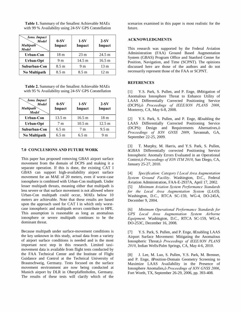
Table 1. Summary of the Smallest Achievable MAEs with 99 % Availability using 24-SV GPS Constellation
Iono. Impact Model Multipath Model
0-SV Impact
1-SV Impact
2-SV Impact
Urban-Con 18 m 23 m 24.5 m Urban-Opt 9 m 14.5 m 16.5 m
Suburban-Con 8.5 m 9 m 13 m No Multipath 8.5 m 8.5 m 12 m
Table 2. Summary of the Smallest Achievable MAEs with 95 % Availability using 24-SV GPS Constellation
Iono. Impact Model Multipath
Model
0-SV Impact
1-SV Impact
2-SV Impact
Urban-Con 13.5 m 16.5 m 18 m Urban-Opt 7 m 10.5 m 12.5 m
Suburban-Con 6.5 m 7 m 9.5 m No Multipath 6.5 m 6.5 m 9 m
7.0 CONCLUSIONS AND FUTURE WORK This paper has proposed removing GBAS airport surface movement from the domain of DCPS and making it a separate operation. If this is done, the existing CAT I GBAS can support high-availability airport surface movement for an MAE of 20 meters, even if worst-case ionosphere is combined with Urban-Con multipath. Under lesser multipath threats, meaning either that multipath is less severe or that surface movement is not allowed where Urban-Con multipath could occur, MAEs below 10 meters are achievable. Note that these results are based upon the approach used for CAT I in which only worst-case ionospheric and multipath errors contribute to HPE. This assumption is reasonable as long as anomalous ionosphere or severe multipath continues to be the dominant threat. Because multipath under surface-movement conditions is the key unknown in this study, actual data from a variety of airport surface conditions is needed and is the most important next step in this research. Limited taxi-movement data is available from flight tests conducted by the FAA Technical Center and the Institute of Flight Guidance and Control at the Technical University of Braunschweig, Germany. Tests focused on the surface movement environment are now being conducted at Munich airport by DLR in Oberpfaffenhofen, Germany. The results of these tests will clarify which of the
scenarios examined in this paper is most realistic for the future.
ACKNOWLEDGMENTS This research was supported by the Federal Aviation Administration (FAA) Ground Based Augmentation System (GBAS) Program Office and Stanford Center for Position, Navigation, and Time (SCPNT). The opinions discussed here are those of the authors and do not necessarily represent those of the FAA or SCPNT.
REFERENCES [1] Y.S. Park, S. Pullen, and P. Enge, “Mitigation of Anomalous Ionosphere Threat to Enhance Utility of LAAS Differentially Corrected Positioning Service (DCPS),” Proceedings of IEEE/ION PLANS 2008, Monterey, CA, May 6-8, 2008. [2] Y.S. Park, S. Pullen, and P. Enge, “Enabling the LAAS Differentially Corrected Positioning Service (DCPS): Design and Requirements Alternatives,” Proceedings of ION GNSS 2009, Savannah, GA, September 22-25, 2009. [3] T. Murphy, M. Harris, and Y.S. Park, S. Pullen, “GBAS Differentially corrected Positioning Service Ionospheric Anomaly Errors Evaluated in an Operational Context,” Proceedings of ION ITM 2010, San Diego, CA, January 25-27, 2010. [4] Specification: Category I Local Area Augmentation System Ground Facility. Washington, D.C., Federal Aviation Administration, FAA-E-2937A, April 17, 2002. [5] Minimum Aviation System Performance Standards for the Local Area Augmentation System (LAAS). Washington, D.C., RTCA SC-159, WG-4, DO-245A, December 9, 2004. [6] Minimum Operational Performance Standards for GPS Local Area Augmentation System Airborne Equipment. Washington, D.C., RTCA SC-159, WG-4, DO-253C, December 16, 2008. [7] Y.S. Park, S. Pullen, and P. Enge, “Enabling LAAS Airport Surface Movement: Mitigating the Anomalous Ionospheric Threat,” Proceedings of IEEE/ION PLANS 2010, Indian Wells/Palm Springs, CA, May 4-6, 2010. [8] J. Lee, M. Luo, S. Pullen, Y.S. Park, M. Brenner, and P. Enge, “Position-Domain Geometry Screening to Maximize LAAS Availability in the Presence of Ionosphere Anomalies,” Proceedings of ION GNSS 2006, Fort Worth, TX, September 26-29, 2006, pp. 393-408.

[9] A. Jahn, H. Bischl, G. Heib, “Channel Characterization for Spread Spectrum Satellite Communication,” IEEE 4th International Symposium on Spectrum Techniques and Applications Proceedings, Volume 3, September 22-25, 1996, pp. 1221-1226. [10] EU-US Cooperation on Satellite Navigation (Working Group C), “Combined Performances for Open GPS/Galileo Receivers,” Final Version, July 19, 2010. [11] C. Hegarty, “Derivation of the Discrimination Function with and without Multipath for the Non-Coherent Dot-Product Discriminator,” MITRE White Paper, November 20, 2009. [12] S. Pullen, Y.S. Park, and P. Enge, “Impact and Mitigation of Ionospheric Anomalies on Ground Based Augmentation of GNSS,” Radio Science, Vol. 44, 2009. [13] S. Ramakrishnan, J. Lee, S. Pullen, and P. Enge, “Targeted Ephemeris Decorrelation Parameter Inflation for Improved LAAS Availability during Severe Ionosphere Anomalies,” Proceedings of ION ITM 2008, San Diego, CA, January 24-26, 2008. [14] D.V. Simili, B. Pervan, “Code-Carrier Divergence Monitoring for the GPS Local Area Augmentation System, Proceedings of IEEE/ION PLANS 2006, San Diego, CA, April 25-27, 2006. [15] ICAO Annex 10, “International Standards and Recommended Practices, - Aeronautical Telecom-munications – Volume I (Radio Navigation Aids),” Amendment 77. [16] C. Shively, “Safety Concepts for Mitigation of Ionospheric Anomaly Errors in GBAS,” Proceedings of ION NTM 2008, San Diego, CA, January 28-30, 2008.


![The GBAS Landing SystemThe GBAS Landing SystemTitle: Microsoft PowerPoint - Boeing GBAS Presentation, Beijing, October 29, 2009.ppt [兼容模式] Author: Shile Created Date: 11/10/2009](https://img.pdfslide.us/doc/110x75/5a727f467f8b9ac0538da536/the-gbas-landing-systemthe-gbas-landing-systemtitle-microsoft-powerpoint-boeing.jpg)