Embed Size (px)
Citation preview

Indian Journal of ChemistryVol. 24A, November 1985, pp. 903-907
A Study of Molecular Geometry with a Modified Point Charge Model
R CUSTODIO* & Y TAKAHATAUniversidade Estadual de Campinas, Instituto de Quimica, Caixa Postal,
6154, 13100, Campinas, Sao Paulo, Brasil
Received 31 October 1984; revised and accepted 12 June 1985
The original form of the point charge model (PCM/I) has been modified in such a way that it permits one to analyse thenature of potential energy of tri- and tetra-atomic molecules. The modified model (PCM/3) predicts bond angles of themolecules as good as, or slightly better than those obtained by PCM/I. Analysis of PCM/3 calculations reveals that lone pairelectrons playa major role in the determination of molecular geometry. Similarity between PCM/3 and the VSEPR theory hasbeen noted.
A simple electrostatic model, or a point charge model(henceforth called PCM/I) proposed by Takahata etal.' has earlier been used by Schnuelle et at? to studythe molecular geometry of polyatomic molecules. Thismethod has been used to calculate bond angles of tri-and tetra-atomic molecules (AHiB), comprising ihydrogen atoms (H) and j other first- or second-rowatoms (B), bound to a central heavy atom (A).Agreements between the calculated values andexperimental ones are satisfactory. PCM/l is a productof effort to explain the Walsh's numerical rules. fromthe view point of valence bond theory. Crystal fieldtheory has been applied to explain the model. Themethod has been justified from molecular orbitaltheory. As an extension we propose, in this paperanother model, called PCM!3 to calculate the bondangles of a molecule AHiBj.
Theoretical ConsiderationsIn PCM/2, of the form (1), a lone pair electronts) is
accomodated in the hybrid orbital of the central heavyatom (A)
.p hyb=(S +ApCM. P)/(l +A ~o.Jl/2 ... (1)
The rationale behind the use of Eq. (1) for a lone pairorbital can be seen if the valence bond model (VB) andPCM/l are compared. The VB model for H20 isdescribed in detail by McWeeny3. Figure 1(a) isessentially equivalent to Fig. 7.7 of Mcweeny '. Thehybrid orbital (h3) in Fig. lfa) has a similarmathematical form as Eq. (1), the only difference beingthat ApCM is replaced by Ava. The hi and h2 are hybridorbitals for the two 0 - H bonds. From the discussionsgiven by Mcweeny", one can easily derive Eq. (2)which expresses Ava as a function of the H - 0 - Hbond angle (0)
Ava = [ -cos 8]1/2. [cos(8/2)]-1 ... (2)
( a)
( b) IJ!hYb
<lJ!hYb I Z JIJ! >hyb
elL
y
-I -I
Fig. I-Comparison of (a) valence bond model (ref. 3); and (b)PCM/I for H20 molecule
If 8 is known, A can be calculated or vice versa. Thesolid line in Fig. 2 is a plot Ava versus 8 of Eq. (2).
The value of APCM in Eq. (1) was fixed as unity inPCM!l (ref. I). ESR experiment provides the ratio ofp-spin density to s-spin density (C~/cl) of AH2 andAB2 type free radicals. Bond angles of several freeradicals have been calculated using PCM together withESR data assuming (C~/cl) = A~CM (ref. 4). The modelhas been found to work reasonably well in predictingthe bond angles of the radicals. Experimental values of),2 are available for some free radicals. However, thereis no simple way to measure experimentally A 2 forclosed shell molecules. One way of predicting ApCM maybe the use of Eq.(2) assuming },pcM:::::;Ava. But there isno logic behind this assumption since the two models
903
INDIAN J. CHEM., VOL. 24A, NOVEMBER 1985
I1I
A IIII
10 1II1
8 IIII
6 III
II
4 II
II
//
2 -,--0
90 120 150 180
bond angle e
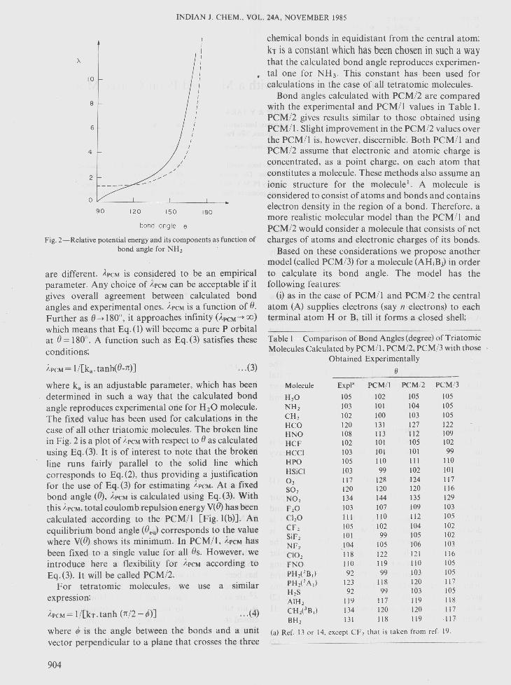
Fig. 2-Relative potential energy and its components as function ofbond angle for NH2
are different. APCMis considered to be an empiricalparameter. Any choice of APCMcan be acceptable if itgives overall agreement between calculated bondangles and experimental ones. APCMis a function of 8.Further as 8-*180°, it approaches infinity (ApCM-*OO)which means that Eq. (1) will become a pure P orbitalat 8= 180°. A function such as Eq.(3) satisfies theseconditions;
APCM= l/[k a- tanh(8-n)] ... (3)
where k, is an adjustable parameter, which has beendetermined in such a way that the calculated bondangle reproduces experimental one for H20 molecule.The fixed value has been used for calculations in thecase of all other triatomic molecules. The broken linein Fig. 2 is a plot of APCMwith respect to 8 as calculatedusing Eq. (3). It is of interest to note that the brokenline runs fairly parallel to the solid line whichcorresponds to Eq. (2), thus providing a justificationfor the use of Eq. (3) for estimating }'PCM.At a fixedbond angle (8), }.PCMis calculated using Eq. (3). Withthis }'PCM,total coulomb repulsion energy V(8) has beencalculated according to the PCM/l [Fig. l(b)]. Anequilibrium bond angle (8eq) corresponds to the valuewhere V(8) shows its minimum. In PCM/l, APCMhasbeen fixed to a single value for all 8s. However, weintroduce here a flexibility for ApCMaccording toEq. (3). It will be called PCM/2.
For tetratomic molecules, we use a similarexpression:
... (4)
where 0/ is the angle between the bonds and a unitvector perpendicular to a plane that crosses the three
904
chemical bonds in equidistant from the central atom;kr is a constant which has been chosen in such a waythat the calculated bond angle reproduces experimen-
• tal one for NH3. This constant has been used forcalculations in the case of all tetratomic molecules.
Bond angles calculated with PCM/2 are comparedwith the experimental and PCM/l values in Table I.PCM/2 gives results similar to those obtained usingPCM/l. Slight improvement in the PCM/2 values overthe PCM/I is, however, discernible. Both PCM/I andPCM/2 assume that electronic and atomic charge isconcentrated, as a point charge, on each atom thatconstitutes a molecule. These methods also assume anionic structure for the molecule". A molecule isconsidered to consist of atoms and bonds and containselectron density in the region of a bond. Therefore, amore realistic molecular model than the PCM/l andPCM/2 would consider a molecule that consists of netcharges of atoms and electronic charges of its bonds.
Based on these considerations we propose anothermodel (called PCM/3) for a molecule (AHiBj) in orderto calculate its bond angle. The model has thefollowing features:
(i) as in the case of PCM/l and PCM/2 the centralatom (A) supplies electrons (say n electrons) to eachterminal atom H or B, till it forms a closed shell;
Table I-Comparison of Bond Angles (degree) of TriatomicMolecules Calculated by PCM/I, PCM/2, PCM/3 with those
Obtained ExperimentallyIJ
Molecule Expla PCM!I PCM!2 PCM!3H20 105 102 105 105NH2 103 101 104 105CH2 102 100 103 105HCO 120 131 127 122HNO 108 113 112 109HCF 102 101 105 102HCCI 103 101 101 99HPO 105 110 111 110HSiCI 103 99 102 10103 117 128 124 117S02 120 120 120 116N02 134 144 135 129F20 103 107 109 103CI20 III 110 112 105CF2 105 102 104 102SiF2 101 99 105 102NF2 ,104 105 106 103CI02 118 122 121 116FNO 110 119 110 105PHi2B,) 92 99 103 105PHi2A,) 123 118 120 117H2S 92 99 103 105AIH2 119 117 119 118CHi3B,) 134 120 120 117BH2 131 118 119 ·117
(a) Ref. 13 or 14. except CF2 that is taken from ref. 19.

CUSTODIO & TAKAHATA: A STUDY OF MOLECULAR GEOMETRY
(ii) two electrons from the terminal atom H or Bareremoved and are placed somewhere between thecentral atom A and the terminal atom H or B. Thecharge of the two electrons is considered to be a pointcharge and it is supposed to be bonding electroniccharge. It is called a bond charge;
(iii) the location of the bond charge is calculatedusing Eq.(5):
R Rx'lI
AC= AB.( n n)XA+XB... (5)
where RAc is the distance between the central atom (A)and the position of the bond charge; XA and XB areelectronegativities of A and B, in Pauling scale; and n ischosen to be 1/3.
Geometry of the molecule takes a form as aconsequence of mutual coulomb repulsions amongpoint charges of the atoms and the bonds.
Results and DiscussionThe results of PCM/3 calculations are listed in
Table I (triatomic molecules) and Table 2 (tetratomicmolecules) together with experimental values as well as
Table2-Bond Angles (degree) of Tetraatomic MoleculesCalculated by PCM/I and PCM/3 Models and Those
Obtained Experimentally or by Theoretical ProceduresPIRAMIDAL
Expl PCM!IMolecule PCM!3 Ref.
OBAB OXAB
107 14106 17106 18109 23110 14106 16110 14106 19107 20110 16110 16110 21115 107 16107 111 16119 105 16108 110 16107 112 161~5 108 16
101 I3103 14103 22101 22101 13111 24
OBAB
NH3 107NF3 1D2NCI3 107CF3 112CH3 120OCI3 116C103- 107PF3 98PeI3 100SiF3 107SiH3 111SO~ - 106H2CF 120HCF2 110H2CC1 119HCCI2 118HSiF2 104H2SiF 114
OCF2 108OCH2 117SCF2 112SCCI2 111OCCl! IIISCH2 117
111120113
111109
114116117115110106
109 111113 110110 112120 109113 109109 110
PLANAR
the other PCMs' values for comparison. The bondlengths used in the calculations are experimental orstandard ones. Variation of 0.20 A from equilibriumbond lengths produces deviation of about 2 degrees inbond angles.
The bond angles calculated with PCM/3 generallyagree well with experimental values considering theapproximate nature of the model. Also noticeable iscloseness of the results of PCM/3 and PCM/I.
The principal advantage of PCM/3 is its capabilityof detailed analysis of the nature of the potentialenergy. First, NH2 molecule is analysed with the aid ofFig. 3 where the relative change of total potentialenergy (VT) as well as its components are plotted. TheVEE curve, i.e. the electronic repulsion, follows the VTcurve closely. On the other hand VNE, i.e. theattraction between nuclei and electrons, and VNN i.e.the repulsion between nuclei, change a little in theopposite direction, mutually cancelling their effect. Itis VEE that determines the bond angle of NH2molecule. The fragmentation of VEE is plotted inFig. 4 for its detail analysis. The repulsion between thelone pair and the bond charges, VEE(LP, QJ, is thedriving force for the decrease in the bond angle from alinear structure to a bent form. On the other hand, therepulsion between the two bond charges, VEE (Qb,QJ, is the driving force for opening the bond angle.These two opposite forces counterbalance at the bondangle near the equilibrium angle. NH2 is bent because
VNE
0,0VNN
-1,0:j
0>-o0:::lJJZlJJ
-2,0
i!.
!.I
IIi
II
iii
IIi
II
iI
//i
/I
//
//
//VT-3,0 --_._._----
VEE
BOND ANGLEFig. 3-Components of electronic repulsion energy for NH2
905
5.0,-------- --.
INDIAN J. CHEM., VOL. 24A, NOVEMBER 1985
120·BOND ANGLE
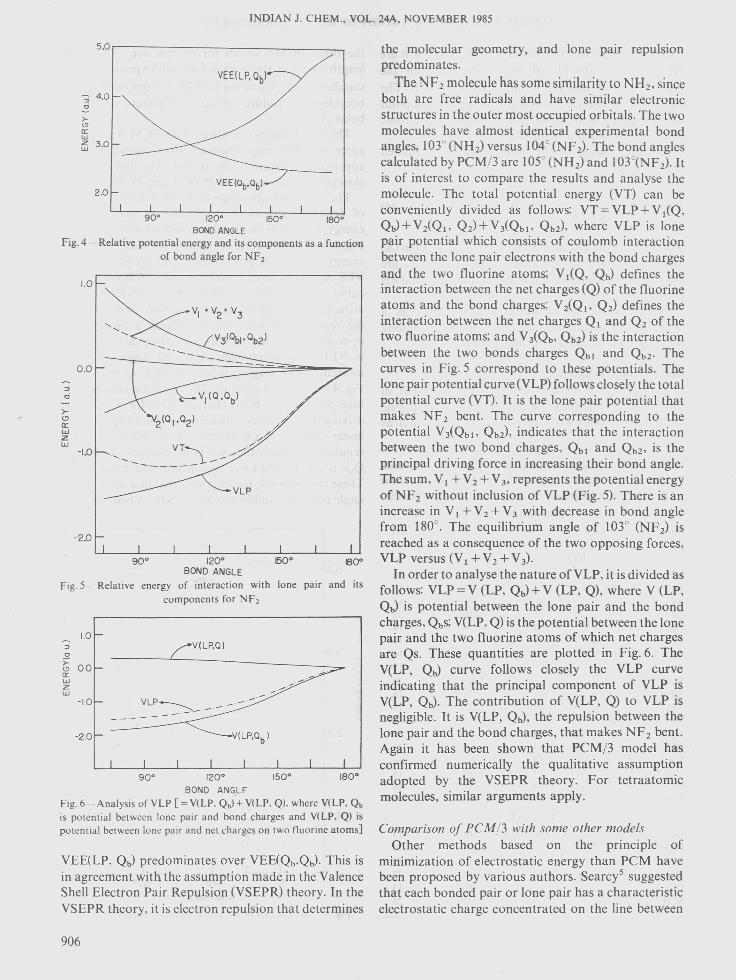
Fig. 4-Relative potential energy and its components as a functionof bond angle for NF 2
0.0
:;;;
0
>-<!l0:::WZw
-1.0 '-.
~ 4.0o
>-<!la::w~ 3.0
90· 120· 1800BOND ANGLE
fig.5-Relative energy of interaction with lone pair and itscomponents for Nf 2
1.0:;;;
0
):00<!l
a::wZw
-La
-2.0
2.0
1.0
V,(O,Ob)
"'2(°,,°2)
VLP
90· 120· ISO· 180·BOND ANGLF
fig. 6-Analysis of VLP [= V(LP. Qb) + V(LP. Q). where V(LP. Qbis potential between lone pair and bond charges and V(LP, Q) ispotential between lone pair and net charges on two fluorine atoms]
-2.0
V(LP,O)
V(LP,Ob)
VEE(LP. Qb) predominates over VEE(Qb.Qb)· This isin agreement with the assumption made in the ValenceShell Electron Pair Repulsion (VSEPR) theory. In theVSEPR theory. it is electron repulsion that determines
906
the molecular geometry, and lone pair repulsionpredominates.
The NF2molecule has some similarity to NH2• sinceboth are free radicals and have similar electronicstructures in the outer most occupied orbitals. The twomolecules have almost identical experimental bondangles, 103° (NH2) versus 104° (NF 2)' The bond anglescalculated by peM/3 are 105° (NH2) and IOnNF2). Itis of interest to compare the results and analyse themolecule. The total potential energy (VT) can beconveniently divided as follows: VT = VLP + V I(Q.QJ+VzCQI' Q2)+ViQbl' Qb2). where VLP is lonepair potential which consists of coulomb interactionbetween the lone pair electrons with the bond chargesand the two fluorine atoms; V1(Q, QJ defines theinteraction between the net charges (Q) of the fluorineatoms and the bond charges; VzCQ I' Q2) defines theinteraction between the net charges QI and Q2 of thetwo fluorine atoms; and ViQb. Qb2) is the interactionbetween the two bonds charges Qbl and Qb2' Thecurves in Fig. 5 correspond to these potentials. Thelone pair potential curve (VLP) follows closely the totalpotential curve (VT). It is the lone pair potential thatmakes NF 2 bent. The curve corresponding to thepotential V iQbl' Qb2). indicates that the interactionbetween the two bond charges. Qbl and Qb2. is theprincipal driving force in increasing their bond angle.The sum. V I + V2 + V3. represents the potential energyof NF 2 without inclusion of VLP (Fig. 5). There is anincrease in V I + V2 + V3 with decrease in bond anglefrom 180°. The equilibrium angle of 103° (NF2) isreached as a consequence of the two opposing forces.VLP versus (V I + V2+ V3)'
In order to analyse the nature ofVLP, it is divided asfollows: VLP=V (LP, QJ+ V (LP, Q), where V (LP,QJ is potential between the lone pair and the bondcharges. QbS;Vtl.P, Q) is the potential between the lonepair and the two fluorine atoms of which net charges'are Qs. These quantities are plotted in Fig. 6. TheYelP, Qb) curve follows closely the VLP curveindicating that the principal component of VLP isYelP, Qb)' The contribution of YelP, Q) to VLP isnegligible. It is Vrl.P, Qb), the repulsion between thelone pair and the bond charges, that makes NF 2 bent.Again it has been shown that peM/3 model hasconfirmed numerically the qualitative assumptionadopted by the VSEPR theory. For tetraatomicmolecules. similar arguments apply.
Comparison of PCM/3 with some other modelsOther methods based on the principle of
minimization of electrostatic energy than peM havebeen proposed by various authors. Searcy" suggestedthat each bonded pair or lone pair has a characteristicelectrostatic charge concentrated on the line between
CUSTODIO & TAKAHATA: A STUDY OF MOLECULAR GEOMETRY
the substituent atom or lone pair. He proposed amethod to find these "electrostatic repulsion number".The equilibrium bond angle is that which minimizesthe electrostatic interactions of these charges.Predicted and reported angles for molecules with lonepair plus two different substituents, XNO, where X= F, Cl, Br, agree well.
Thompson" assumed that bonding and lone pairsare point charges distributed on a spherical surface.These point charges are assumed to be the radii (r) andtheir equilibrium position is found by means of theminimization of a repulsion potential of the form l/r".
These two models permit the prediction of bondangles with comparable accuracy. Although both themethods agree with the importance of the lone pairs inthe determination of the molecular geometry, they donot give detail information about the nature of theinteractions involved. PCM/3 cannot only predictmolecular geometry, but also provides additionalinformation about the nature of molecular geometry.The explanation of the nature of interactions areobtained by the familiar language of chemistry such asinteraction between bond pair-bond pair or lone pair-bond pair.
There is a certain similarity between ab-initioFloating Spherical Gaussian Orbital (FSGO) modeldeveloped by Frost 7 and PCM/3. PCM/3 can beconsidered as a simplification of FSGO. In FSGOmodel, any pair of electrons is represented by aspherical gaussian orbital. If we consider any pair ofelectrons as a point charge we have PCM/3. FSGO and~CM/3 have two parameters to be adjusted. In theFSGO model these are the orbital radius and theposition of its center for any gaussian. Both theparameters are adjustable. In PCM/3 model, these arethe parameter (k) of Eq. (3) or (4), that reflects the sizeof lone pair, and the parameter (n) of Eq. (5) thatdetermines the position of the bond pairs. Acomparison of the PCM/3 with FSGO calculationsshows a similar qualitative behaviour of some energyterms", For example, the VEE(Qb, QJ, VEE(LP, Qb)and others obtained for H20 molecule with FSGOcalculations have similar qualitative tendencycorresponding to the PCM/3 energies. The pooragreement between calculated and experimental bondangles ohtained by FSGO for triatomic hydrides"reflects the necessity of a better representation of theelectron pairs than a simple spherical gaussian Io. Maybe an improvement in FSGO as that shown inreference (10) could bring a general agreement betweenthe behaviour of energy terms of PCM/3 and FSGO.
An advantage of PCM/3 is that it can be used forgreater number of molecules with closed or open shell,or that containing heavy atoms like Br, 1, etc. Incontrast, the calculation of molecules with heavy
atoms by FSGO is very difficult and require thatpseudopotential be used 11. FSGO model has not beendeveloped yet for calculations of open shell systems.
The principal advantage of PCM/3 is that it makespossible the analysis of energy in fragments. Thequalitative agreement in many aspects between FSGOmodel and PCM/3 gives us confidence in the resultsand conclusions obtained by PCM 3. PCM 3 can beviewed, also, as a mathematical model that embodies,in a certain way, the qualitative ideas of VSEPR.
More rigorous ab-initio calculations using localizedorbitals for a set of tri- and tetra-atomic molecules 12
has shown that the order of importance of themolecular interactions agree with the VSEPRprediction and consequently with PCM/3 results, i.e.(LP -Qb) >(Qb -Qb)'
AcknowledgementR C wishes to thank F APESP (Fundacao de
Amparo a Pesquisa do Estado de Sao Paulo) for ascholarship, and Y T thanks CNPq (ConselhoNacional de Desenvolvimento Cientifico e Tecno-logico) for a scholarship and a research fund.
ReferencesI Takahata Y. Schnuelle G W & Parr R G. J Am chem Soc. 93
(1971) 593.2 Schnuelle G W & Parr R G. J Am chem Soc. 94 (1972) 8974.3 McWeeny R. Coulson's faience (Oxford University Press.
Oxford) 1979. 195.4 Tak ahata Y. Eri T & I'Haya Y J. Chern Phvs Lett. 26 (1974) 557.5 Searcy A W. J chem Phys. 28 (1958) 1237: Searcy A W. J chem
Phys, 31 (1959) J. Parsons A E & Searcy A W, J chern Phys,
30 (1959) 1635.6 Thompson H B. J Am chem Soc. 93 (1971) 4609.7 Frost A A. J chem Phvs, 47 (1967) 3707. 3714.8 Afzal M & Frost A A. lnt J Quantum Chern, 7 (1973) 51.9 Frost A A. J phys Chern. 72 (1968) 1289.
10 Rouse R A & Frost A A. J chem Phvs. 50 (1969) 1705.II Toman J J. Frost A A. Topiol S. Jacobson S & Ratner M A.
TheaI' chim Acta. 58 (1981) 285.12 Schmie de Kamp A. Cruickshank D W J. Skaarup S. Pulay P.
Hargittai I & Boggs J E. J Am chem Soc. 101 (1979) 202.13 Herzberg G. in Electronic spectra ofpolyatomic molecules (Van
Nostrand, Princeton. New York) 1966.14 Suton L E. in Tables ofinteratomic distances and configurations in
molecules and ions (The Chern Real Society. London) 1958.15 Calder V. Mann D E. Seshadri K S. Allavcna M & White D. J
chem Phvs. 51 (1969) 2093.16 Biddcs I & Hydson A. Malec Phvs, 25 (1973) 797.17 Otake M. Matsumura C & Morino Y. J 11101 Spectrosc. 28 (1968)
316.18 Burgi H B. Stedman D & Bartell L S. J 11101 Spectrosc. 53 (1974)
37.19 Kamashina Y & Cox A P. J 11101 Spectrosc, 65 (1977) 319.20 Kiskiuk P & Townes C A. J chem Phvs, 18 (1950) 1109.21 Miinisto L & Larson L O. Arra Crvstollogr, 829 (1973) 623.22 Hoper M J. Russell J W & Overend J. Spectrochim Acta. 28A
(1.972) 1215.23 Fessendcr R W & Schuler R H. J chem Phvs, 43 (1965) 2704.24 Johnson D R. Powell F X & Kirchoff W H. J 11101 Spectrosc, 39
(1971) 136.
907