Embed Size (px)
Citation preview
A study of breakout of a continuously cast steel slab due to surface cracks
F. Kavička1, J. Dobrovská2, K. Stránský1, B. Sekanina1, J. Stetina1, M. Masarik3, T. Mauder1
& Z. Franek4
1Brno University of Technology, Czech Republic 2VSB-TU Ostrava, Czech Republic 3EVRAZ VITKOVICE STEEL, a.s, Czech Republic 4Faculty of Business Administration, Karvina, Czech Republic
Abstract
The solidification and cooling of a continuously cast slab and the simultaneous heating of the mold is a very complicated problem of three-dimensional transient heat and mass transfer. The solving of such a problem is impossible without numerical models of the temperature field. Experimental research and measurements must be carried out simultaneously with numerical computation. An important area of the caster is the so-called secondary cooling zone, which is subdivided into thirteen sections. In the secondary cooling zone, where the slab begins to straighten, a breakout of the steel can occur at the points of increased local chemical and temperature heterogeneity of the steel, due to increased tension resulting from the bending of the slab, and also due to high local concentration of non-metallic, slag inclusions. The changes in the chemical composition of the steel, during the actual continuous casting, are especially dangerous. In the case of two immediate consequent melts this could lead to immediate interruption of the continuous casting and to a breakout. The temperature field of a slab was calculated by means of original numerical model before, as well as after the breakout and the calculated parameters were collected. If the dimensionless analysis is applied for assessing and reducing the number of these parameters, then it is possible to express the level of a risk of breakout as the function of five dimensionless criteria. Keywords: continuously cast slabs, oscillation marks, hooks, chemical composition, breakout.
Surface Effects and Contact Mechanics X 85
www.witpress.com, ISSN 1743-3533 (on-line) WIT Transactions on Engineering Sciences, Vol 71, © 2011 WIT Press
doi:10.2495/SECM110081
1 Introduction
Oscillation marks are transverse grooves forming on the surface of the solidifying shell of a continuously cast slab. The course of individual marks is rough and perpendicular to the direction of the slab movement. The formation of the marks is sometimes the result of the bending of the solidifying shell during the oscillation of the mould, which depends on the frequency and the amplitude of the oscillation and on the casting (movement) speed. The hooks are solidified microscopically thin surface layers of steel – as described by various authors (Badri et al. [1], Thomas et al. [2], Ojeda et al. [3]). They are covered with oxides and slag. Their microstructure is different to that of the base material of the solidifying shell. The formations of the oscillation marks and hooks are related. The depth of the oscillation marks and also their shapes, size and the microstructure of the hooks vary irregularly. An increasing extent of these changes leads to a defect in the shape of a crack, which reduces the thickness of the solidified shell of the slab upon its exit from the mould, and it causes a dangerous notch. In the secondary cooling zone, where the slab begins to straighten, a breakout of the steel can occur at the points of increased local chemical and temperature heterogeneity of the steel, due to increased tension resulting from the bending of the slab and also due to high local concentration of non-metallic, slag inclusions. The changes in the chemical composition of the steel, during the actual continuous casting, are especially dangerous. The consequences of this operational immediate change in the chemical composition of the steel, which are not prevented by a breakout system directly inside the mould (Pyszko et al. [4]), could lead to immediate interruption in the continuous casting and to a breakout at a greater distance from the mould than usually, thus leading to significant material losses and downtime.
2 Interruption of continuous casting
The following case was recorded during the process of continuous casting of 250×1530 mm steel slabs of the grade A with the 0.41 wt.% carbon content and 9.95 wt.% chromium content (melts 1 to 3), and grade B steel with the 0.17 wt.% carbon content and 0.70 wt.% chromium content (melt 4). The casting of the first two melts of the grade A took place without any significant problems, after the casting of the third melt of the grade A, the fourth melt of the grade B followed. The change in the chemical compositions of the steels of both grades was carried out very quickly by changing the tundish. Inside the mould, the steel B mixed with the steel A of the previous melt. The pouring continued for another 20 minutes, but then, a breakout occurred between the 7th and 8th segments and the caster stopped at the unbending point of the slab, at a distance of 14.15 m away from the level of the melt inside the mould. The height difference between the level inside the mould and the breakout point was 8.605 m. This tear in the shell occurred on the small radius of the caster (Fig. 1a). A 250 mm thick sample was taken from the breakout area using a longitudinal axial cut. The structure of this
86 Surface Effects and Contact Mechanics X
www.witpress.com, ISSN 1743-3533 (on-line) WIT Transactions on Engineering Sciences, Vol 71, © 2011 WIT Press

sample and the distribution of sulphur was analyzed on the basis of the Bauman print (Fig. 2) as well. The numbers 1 to 11 indicate the positions of the samples in the places around the breakout intended for analysis (Fig. 1b). Simultaneously, significant 25 mm sulphide segregations were discovered – very heterogeneous areas created by the original base material of the slab (melt 3, steel of the grade A), the new material of the slab (melt 4, steel of the grade B) and between them, and also in the areas of mixed composition. Beneath the surface of the slab, at a
Figure 1: a) Macro-structure of the breakout; b) Sampling scheme.
Figure 2: Baumann print.
Surface Effects and Contact Mechanics X 87
www.witpress.com, ISSN 1743-3533 (on-line) WIT Transactions on Engineering Sciences, Vol 71, © 2011 WIT Press
depth of 75 to 85 mm, there were cracks and a zone of columnar crystals oriented towards the surface of the slab on the small radius. This was identical to the orientation of the groove, which gradually turned into a crack (Fig.1b – direction 4 – 6) and, on the opposite surface of the slab, the hook, which was covered by melt (position 8). During the first phase of the analyses, the objective was to determine the material, physical, chemical and technological parameters, which differed in both melts 3 and 4 (besides the already introduced chemical composition). Table 1 presents the individual parameters of both melts.
3 Numerical model of the slab temperature field
The original numerical model takes into account the temperature field of the entire slab (from the meniscus of the level of the melt in the mould to the cutting torch) using a 3D mesh (Stetina et al. [5]). The solidification and cooling of a continuously cast slab is a global problem of 3D transient heat and mass transfer. If heat conduction within the heat transfer in this system is decisive, the process is described by the Fourier-Kirchhoff equation. It describes the temperature field of the solidifying slab in its all three states: at the temperatures above the liquidus (i.e. the melt), within the interval between the liquidus and solidus (i.e. in the mushy zone) and at the temperatures below the solidus (i.e. the solid state). In order to solve these, it is convenient to use the explicit numerical method of finite differences. Numerical simulation of the release of latent heats of phase or structural changes is carried out by introducing the enthalpy function dependent on temperature. The numerical model fully considers the non-linearity of the task, i.e. the dependence of the thermo-physical properties, especially of the continuously cast material and the mould on the temperature, as it does the dependence of the boundary conditions on surface temperature and other influences (shift rate, cooling intensity, etc.). The 3D model had first been designed as an off-line version and later as an on-line version, so that it could work in real time. After correction and testing, it will be possible to implement it on any caster, thanks to the universal nature of the code. The off-line model analyses the temperature field of the actual continuous casting, while it passes through the primary-, secondary- and tertiary cooling zones, i.e. through the entire caster. The model is fully functional and accurately conducts general analyses of the influences of the various technological measures on the formation of the temperature field of the entire continuous casting. In a similar way, it helps the staff to analyse the failure state of the caster. The off-line version of the temperature model was used now to simulate the temperature field of the steel slab from the melt No. 3 (steel grade A), steel slab from the melt No. 4 (steel grade B) and a mixture of A and B grades. We consider that each thermo-physical property (thermal conductivity, heat capacity, density and enthalpy) of the mixture A + B is the arithmetic average of the properties of steels A and B. The dependence of these parameters on temperature was observed (Dobrovska et al. [6]). The model solves the temperature history of every point of the cross-section during its movement through the whole caster. The model also provides the curves of isoliquidus (red) and isosolidus (blue).
88 Surface Effects and Contact Mechanics X
www.witpress.com, ISSN 1743-3533 (on-line) WIT Transactions on Engineering Sciences, Vol 71, © 2011 WIT Press
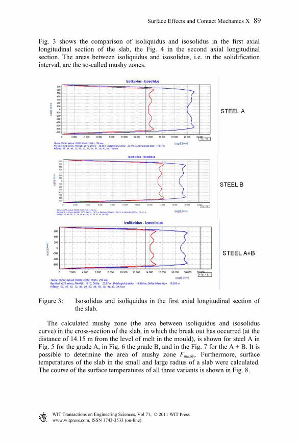
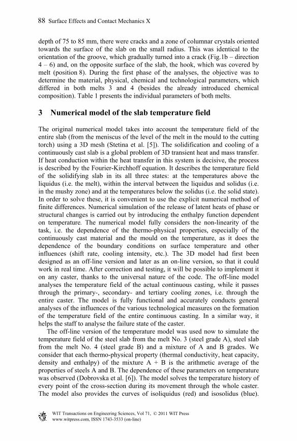
Fig. 3 shows the comparison of isoliquidus and isosolidus in the first axial longitudinal section of the slab, the Fig. 4 in the second axial longitudinal section. The areas between isoliquidus and isosolidus, i.e. in the solidification interval, are the so-called mushy zones.
Figure 3: Isosolidus and isoliquidus in the first axial longitudinal section ofthe slab.
The calculated mushy zone (the area between isoliquidus and isosolidus curve) in the cross-section of the slab, in which the break out has occurred (at the distance of 14.15 m from the level of melt in the mould), is shown for steel A in Fig. 5 for the grade A, in Fig. 6 the grade B, and in the Fig. 7 for the A + B. It is possible to determine the area of mushy zone Fmushy. Furthermore, surface temperatures of the slab in the small and large radius of a slab were calculated. The course of the surface temperatures of all three variants is shown in Fig. 8.
Surface Effects and Contact Mechanics X 89
www.witpress.com, ISSN 1743-3533 (on-line) WIT Transactions on Engineering Sciences, Vol 71, © 2011 WIT Press
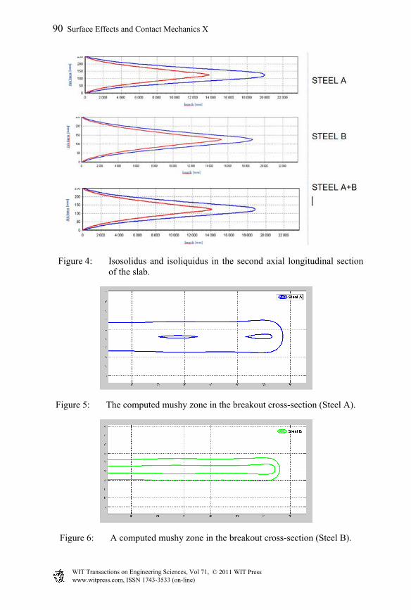
Figure 4: Isosolidus and isoliquidus in the second axial longitudinal section of the slab.
Figure 5: The computed mushy zone in the breakout cross-section (Steel A).
Figure 6: A computed mushy zone in the breakout cross-section (Steel B).
90 Surface Effects and Contact Mechanics X
www.witpress.com, ISSN 1743-3533 (on-line) WIT Transactions on Engineering Sciences, Vol 71, © 2011 WIT Press
Figure 7: A computed mushy zone in the breakout cross-section (Steel A+B).
Figure 8: The surface temperature of the slab in the large (upper curve-blue) and small radius (lower curve-red).
Surface Effects and Contact Mechanics X 91
www.witpress.com, ISSN 1743-3533 (on-line) WIT Transactions on Engineering Sciences, Vol 71, © 2011 WIT Press
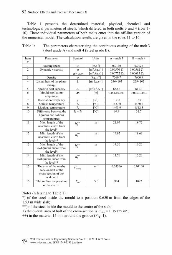
Table 1 presents the determined material, physical, chemical and technological parameters of steels, which differed in both melts 3 and 4 (row 1-10). These individual parameters of both melts enter into the off-line version of the numerical model. The calculation results are given in the rows 11 to 16.
Table 1: The parameters characterizing the continuous casting of the melt 3 (steel grade A) and melt 4 (Steel grade B).
Item #
Parameter Symbol Units A – melt 3 B – melt 4
1 Pouring speed w [m.s-1] 0.0130 0.0126 2 Dynamic viscosity [m-1.kg.s-1] 0.00570 TL 0.00562 TL = . [m-1.kg.s-1] 0.00772 TS 0.00615 TS 3 Density [kg.m-3] 7560.7 7600.9 4 Latent heat of the phase
change L [m2.kg.s-2] 246×103 259×103
5 Specific heat capacity cp [m2.s-2.K-1] 632.6 611.0 6 Mould oscillation
amplitude S [m] 0.0060.003 0.0060.003
7 Oscillation frequency f [s-1] 1.533 1.533 8 Solidus temperature TS [°C] 1427.0 1480.6 9 Liquidus temperature TL [°C] 1493.9 1512.3 10 Difference between the
liquidus and solidus temperatures
TL – TS [°C] 66.9 31.7
11 Max. length of the isosolidus curve from
the level*
max
Sh m 21.07 19.72
12 Min. length of the isosolidus curve from
the level**
min
Sh m 19.92 18.69
13 Max. length of the isoliquidus curve from
the level*
max
Lh m 14.50 16.20
14 Min. length of the isoliquidus curve from
the level**
min
Lh m 13.70 15.20
15 The area of the mushy zone on half of the cross-section of the
breakout +
mushyF m2 0.05366 0.04100
16 The surface temperature of the slab++
Tsurf °C 934 1097
Notes (referring to Table 1): *) of the steel inside the mould to a position 0.650 m from the edges of the 1.53 m wide slab; **) of the steel inside the mould to the centre of the slab; +) the overall area of half of the cross-section is Fslab = 0.19125 m2; ++) in the material 15 mm around the groove (Fig. 1).
92 Surface Effects and Contact Mechanics X
www.witpress.com, ISSN 1743-3533 (on-line) WIT Transactions on Engineering Sciences, Vol 71, © 2011 WIT Press
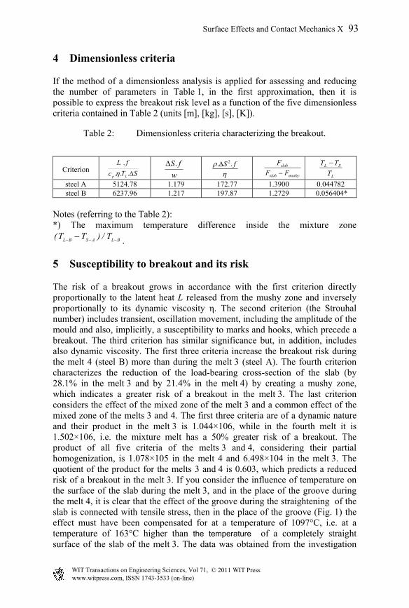
4 Dimensionless criteria
If the method of a dimensionless analysis is applied for assessing and reducing the number of parameters in Table 1, in the first approximation, then it is possible to express the breakout risk level as a function of the five dimensionless criteria contained in Table 2 (units [m], [kg], [s], [K]).
Table 2: Dimensionless criteria characterizing the breakout.
Criterion
steel A 5124.78 1.179 172.77 1.3900 0.044782 steel B 6237.96 1.217 197.87 1.2729 0.056404*
Notes (referring to the Table 2): *) The maximum temperature difference inside the mixture zone
BLASBL T/)TT( .
5 Susceptibility to breakout and its risk
The risk of a breakout grows in accordance with the first criterion directly proportionally to the latent heat L released from the mushy zone and inversely proportionally to its dynamic viscosity η. The second criterion (the Strouhal number) includes transient, oscillation movement, including the amplitude of the mould and also, implicitly, a susceptibility to marks and hooks, which precede a breakout. The third criterion has similar significance but, in addition, includes also dynamic viscosity. The first three criteria increase the breakout risk during the melt 4 (steel B) more than during the melt 3 (steel A). The fourth criterion characterizes the reduction of the load-bearing cross-section of the slab (by 28.1% in the melt 3 and by 21.4% in the melt 4) by creating a mushy zone, which indicates a greater risk of a breakout in the melt 3. The last criterion considers the effect of the mixed zone of the melt 3 and a common effect of the mixed zone of the melts 3 and 4. The first three criteria are of a dynamic nature and their product in the melt 3 is 1.044×10⁶, while in the fourth melt it is 1.502×10⁶, i.e. the mixture melt has a 50% greater risk of a breakout. The product of all five criteria of the melts 3 and 4, considering their partial homogenization, is 1.078×10⁵ in the melt 4 and 6.498×10⁴ in the melt 3. The quotient of the product for the melts 3 and 4 is 0.603, which predicts a reduced risk of a breakout in the melt 3. If you consider the influence of temperature on the surface of the slab during the melt 3, and in the place of the groove during the melt 4, it is clear that the effect of the groove during the straightening of the slab is connected with tensile stress, then in the place of the groove (Fig. 1) the effect must have been compensated for at a temperature of 1097°C, i.e. at a temperature of 163°C higher than the temperature of a completely straight surface of the slab of the melt 3. The data was obtained from the investigation
STc
fL
Lp ...
.
w
fS.
fS .. 2mushyslab
slab
FF
F
L
SL
T
TT
Surface Effects and Contact Mechanics X 93
www.witpress.com, ISSN 1743-3533 (on-line) WIT Transactions on Engineering Sciences, Vol 71, © 2011 WIT Press
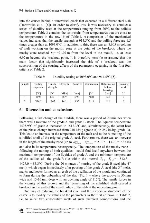
into the causes behind a transversal crack that occurred in a different steel slab (Dobrovska et al. [6]). In order to clarify this, it was necessary to conduct a series of ductility tests at the temperatures ranging from 20°C to the solidus temperature. Table 3 contains the test results from temperatures that are close to the temperatures in the row 16 of Table 1. A comparison of the mechanical values indicates that the tensile strength at 914.5°C and the pulling force are 1.5 times greater than at 1093.0°C. In addition to this, there was an 8.605 m column of melt working on the mushy zone at the point of the breakout, where the mushy zone reached max
Sh =21.07 m from the level in the mould, i.e. at least
6.92 m beyond the breakout point. It is therefore possible to assume that the main factor that significantly increased the risk of a breakout was the superposition of the causing effects of the parameters occurring in the first four criteria of Table 2.
Table 3: Ductility testing at 1093.0°C and 914.5°C [5].
Sample Testing temperature
Tensile strength
Strength Diameter Contraction Deformation before
breaking
Breaking work
[°C] [N] [MPa] [mm] [%] [mm] [ J] 1 1093 817 28.9 3.90 58.0 12.0 7
2 914.5 1247 44.1 5.35 21.5 5.5 6
6 Discussion and conclusions
Following a fast change of the tundish, there was a period of 20 minutes when there was a mixture of the grade A and grade B steels. The liquidus temperature 1493.9°C of grade A increased to 1512.3°C and, simultaneously, the latent heat of the phase change increased from 246 kJ/kg (grade A) to 259 kJ/kg (grade B). This led to an increase in the temperature of the melt and to the re-melting of the solidified shell of the original grade A steel. Furthermore, there was an increase in the length of the mushy zone (up to max
melt.3Sh minmelt.3Lh = 21.07 13.70 = 7.37 m)
and also in its temperature heterogeneity. The temperature of the mushy zone – following the mixing of both qualities – could find itself anywhere between the maximum temperature of the liquidus of grade A and the minimum temperature of the solidus of the grade B (i.e. within the interval ASBL TT = 1512.3 –
1427.0 = 85.3°C. During the 20 minutes of pouring of the grade B steel (the 4th melt), which began immediately after pouring of the grade A steel (the 3rd melt), marks and hooks formed as a result of the oscillation of the mould and continued to form during the unbending of the slab (Fig. 1 – where the groove is 50 mm wide and 15-16 mm deep with an opening angle of 115°). The tensile forces in the vicinity of this groove and the re-melting of the solidified shell caused a breakout in the wall of the small radius of the slab at the unbending point. One way of reducing the breakout risk and the successive shutdown of the caster is to modify the values of the parameters in the first criterion in Table 2, i.e. to select two consecutive melts of such chemical compositions and the
94 Surface Effects and Contact Mechanics X
www.witpress.com, ISSN 1743-3533 (on-line) WIT Transactions on Engineering Sciences, Vol 71, © 2011 WIT Press
corresponding physical and chemical parameters (from which the dimensionless criteria are determined) that the criteria predict the zero-breakout.
Acknowledgements
This analysis was conducted using a program devised within the framework of the GACR projects Nos. 106/08/0606, 106/09/0940, 106/09/0969 and P107/11/1566.
References
[1] Badri, A. et al., Metallurgical and Materials Transactions B, Vol. 36 B, p.373-383, 2005.
[2] Thomas, B.G., Sengupta, J. & Ojeda, C., Mechanism of Hook and Oscillation Mark Formation in Ultra-Low Carbon Steel. Proc. of the Second Baosteel Biennial Conference, Shanghai, PRC, Vol.1, pp. 112-117, 2006.
[3] Ojeda, C. et al., Mathematical Modelling of Thermal-Fluid Flow in the Meniscus Region During an Oscillation Cycle. AISTech 2006, Vol.1, pp. 1017-1028, 2006.
[4] Pyszko, R. et al., On-line Numerical Model of Solidification for Continuous Casting Integrated with Monitoring and Breakout Prediction System. Proc. of the MicroCAD 2008 International Scientific Conference. University of Miskolc, Miskolc, pp. 95-97, 2008.
[5] Stetina, J. et al., Optimization of technology and control of a slab caster. I. Off-line numerical model of temperature field of a slab a parametric studies. Hutnicke listy LXIII, No. 1, pp. 43-52, 2010.
[6] Dobrovska, J. et al., Materials Science Forum Vols. 567-568, pp. 105-108, 2008.
Surface Effects and Contact Mechanics X 95
www.witpress.com, ISSN 1743-3533 (on-line) WIT Transactions on Engineering Sciences, Vol 71, © 2011 WIT Press