Embed Size (px)
Citation preview

Copyright© 2018 by Turbomachinery Laboratory, Texas A&M Engineering Experiment Station
A Study on the Operation of Pitot Tube Pumps
Bryce Neilson, P.E. Research and Development Engineering Manager Weir Specialty Pumps Salt Lake City, Utah, USA
Bryce Neilson graduated in 2004 from the University of Utah with a Bachelor of Science in Mechanical Engineering. For five years he worked as a Design Engineer at Water Design, Inc. In 2006, Bryce began work at Weir Specialty Pumps as a Design/Test Engineer and ten years later he has advanced to manage the Research & Development department. He has been a licensed Professional Engineer since 2010, is an ISO 18436 Category III Vibration Analyst, and most recently invented the Roto-Jet® RO-FT pitot tube pump.
ABSTRACT While pitot tube pumps have been commercially available since 1970 little is known and less is published about their internal operation and design principles especially when operating off design. This paper is a culmination of research conducted over the past several years aimed at understanding the internal operation of pitot tube pumps in their different configurations. This research includes computational fluid dynamic (CFD) studies, and laboratory testing. While pitot tube pumps are classified as centrifugal pumps since they add energy to the fluid by increasing the fluid angular momentum and such follow many of the same laws. However, due to their unique construction they operate differently that typical “impeller” pumps. Understanding these differences is imperative in their successful application. INTRODUCTION Pitot tube pumps excel in low flow high head applications (nq = 1.2-7 (rpm)) and can operate reliably throughout their full curve (shutoff to runout) without damage. They operate with efficiencies in range of 50%-65%. They can operate at speeds up to 6000 rpm and can generate heads up to 1700 m with best efficiency point (BEP) flow rates of 4.5-114 m2/h without pressure pulsations. Pump capacity is determined by the size and number of pitot tube openings or blades. Pump head is determined by pump speed and diameter of the rotating case. Since pitot tube pumps do not have an impeller they do not exhibit from recirculation or flow separation at flow rates away from the BEP. The hydraulic bearing loads are minimal or non-existent and vary little if at all with respect to flow rate. This extends the allowable flow rate from shut off the end of curve without incurring any mechanical distress. Pitot tube pumps are capable of low NPSHr without the use of an inducer and exhibit stable suction characteristics through their full operating range. A mechanical seal(s) is used to seal the rotating case. This seal(s) is exposed to only suction pressure. Pitot Tube Pump Construction Besides the items required to support a rotating body (i.e. bearing frame and bearings) all pitot pumps are composed of three major parts. Two of these parts make up the rotating case; the rotor cover and rotor. The pitot tube is placed in the center of the rotating case, and has an opening facing opposite the direction of rotation near the periphery of the case. Fluid enters the opening where the tangential velocity is diffused into pressure and conveyed back to the center of the pump where it is discharged via the shaft supporting the pitot tube (figures 1 and 2). Pitot tube pumps are most commonly available in either coaxial suction and discharge arrangement (figure 1) or a flow through arrangement (figure 2) where the suction and discharge are opposed. The important difference between the two is how the pitot tube penetrates the rotating case. In the coaxial arrangement, the pitot tube penetrates through the eye of rotor cover increasing the NPSHr,
Copyright© 2018 by Turbomachinery Laboratory, Texas A&M Engineering Experiment Station
especially on light hydrocarbons. This arrangement is subject to hydraulic thrust; however, it requires only one seal. The coaxial arrangement is typically offered as an overhung rotating case. In the flow through arrangement, the pitot tube penetrates the rotor. This decreases NPSHr and eliminates all hydraulic thrust. The flow through arrangement requires two seals and a tangential drive, this is typically accomplished via a gear drive. The flow through arrangement is typically offered as a between bearings rotating case. Pitot tube pumps typically operate at speeds above two pole motor speeds and require a speed increasing gearbox either mounted external or internal to the bearing frame.
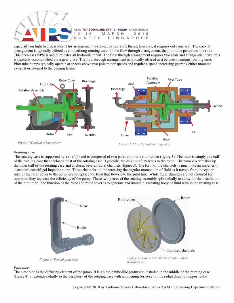
Rotating case The rotating case is supported by a shaft(s) and is composed of two parts; rotor and rotor cover (figure 3). The rotor is simply one half of the rotating case that encloses most of the rotating case. Typically, the drive shaft attaches to the rotor. The rotor cover makes up the other half of the rotating case and encloses several radial channels (figure 3). The form of the channels is much like an impeller in a standard centrifugal impeller pump. These channels aid in increasing the angular momentum of fluid as it travels from the eye or inlet of the rotor cover to the periphery to replace the fluid that flows into the pitot tube. While these channels are not required for operation they increase the efficiency of the pump. These two pieces of the rotating assembly split radially to allow for the installation of the pitot tube. The function of the rotor and rotor cover is to generate and maintain a rotating body of fluid with in the rotating case.
Pitot tube The pitot tube is the diffusing element of the pump. It is a simple tube-like protrusion installed in the middle of the rotating case (figure 4). It extends radially to the periphery of the rotating case with an opening (or nose) in the radial direction opposite the
Suction
Pitot tube
Rotating Assembly
Seal
DischargeRotor Cover
Discharge
Suction
Pitot Tube
Gear
Rotating Assembly
Drive Seal
Seal
Rotor
Figure 2: Flow through arrangement Figure 1:Coaxial arrangement
Enclosed channels
Rotorcover Rotor
Figure 3:Rotor cover channels (rotor cover transparent)
Figure 4: Typical pitot tube
Nose
Blade
Copyright© 2018 by Turbomachinery Laboratory, Texas A&M Engineering Experiment Station
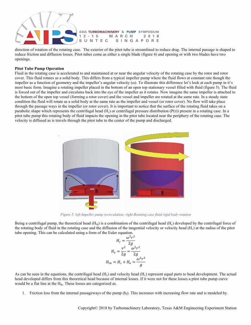
direction of rotation of the rotating case. The exterior of the pitot tube is streamlined to reduce drag. The internal passage is shaped to reduce friction and diffusion losses. Pitot tubes come as either a single blade (figure 4) and opening or with two blades have two openings. Pitot Tube Pump Operation Fluid in the rotating case is accelerated to and maintained at or near the angular velocity of the rotating case by the rotor and rotor cover. This fluid rotates as a solid body. This differs from a typical impeller pump where the fluid flows at constant rate though the impeller as a function of geometry and the impeller’s angular velocity (ω). To illustrate this difference let’s look at each pump in it’s most basic form. Imagine a rotating impeller placed in the bottom of an open top stationary vessel filled with fluid (figure 5). The fluid is forced out of the impeller and circulates back into the eye of the impeller as it rotates. Now imagine the same impeller is attached to the bottom of the open top vessel (forming a rotor cover) and the vessel and impeller are rotated at the same rate. In a steady state condition the fluid will rotate as a solid body at the same rate as the impeller and vessel (or rotor cover). No flow will take place through the passage ways in the impeller (or rotor cover). It is important to notice that the surface of the rotating fluid takes on a parabolic shape which represents the centrifugal head (Hc) or centrifugal pressure distribution (P(r)) present in a rotating case. In a pitot tube pump this rotating body of fluid impacts the opening in the pitot tube located near the periphery of the rotating case. The velocity is diffused as is travels through the pitot tube to the center of the pump and discharged.
Figure 5: left-Impeller pump recirculation; right-Rotating case fluid rigid body rotation
Being a centrifugal pump, the theoretical head (Hth) is a combination of the centrifugal head (Hc) developed by the centrifugal force of the rotating body of fluid in the rotating case and the diffusion of the tangential velocity or velocity head (Hv) at the radius of the pitot tube opening. This can be calculated using a form of the Euler equation.
2
2 2
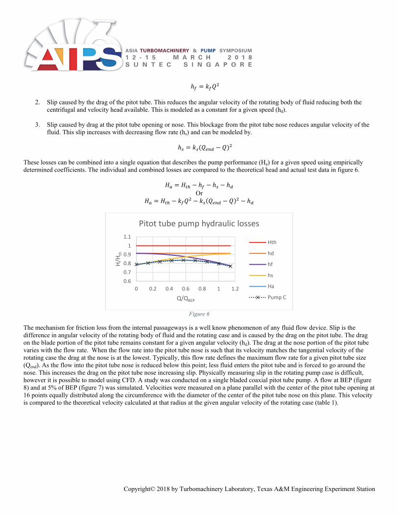
As can be seen in the equations, the centrifugal head (Hc) and velocity head (Hv) represent equal parts to head development. The actual head developed differs from this theoretical head because of internal losses. If it were not for these losses a pitot tube pump curve would be a flat line at the Hth. These losses are categorized as.
1. Friction loss from the internal passageways of the pump (hf). This increases with increasing flow rate and is modeled by.
Copyright© 2018 by Turbomachinery Laboratory, Texas A&M Engineering Experiment Station
2. Slip caused by the drag of the pitot tube. This reduces the angular velocity of the rotating body of fluid reducing both the
centrifugal and velocity head available. This is modeled as a constant for a given speed (hd).
3. Slip caused by drag at the pitot tube opening or nose. This blockage from the pitot tube nose reduces angular velocity of the fluid. This slip increases with decreasing flow rate (hs) and can be modeled by.
These losses can be combined into a single equation that describes the pump performance (Ha) for a given speed using empirically determined coefficients. The individual and combined losses are compared to the theoretical head and actual test data in figure 6.
Or
Figure 6
The mechanism for friction loss from the internal passageways is a well know phenomenon of any fluid flow device. Slip is the difference in angular velocity of the rotating body of fluid and the rotating case and is caused by the drag on the pitot tube. The drag on the blade portion of the pitot tube remains constant for a given angular velocity (hd). The drag at the nose portion of the pitot tube varies with the flow rate. When the flow rate into the pitot tube nose is such that its velocity matches the tangential velocity of the rotating case the drag at the nose is at the lowest. Typically, this flow rate defines the maximum flow rate for a given pitot tube size (Qend). As the flow into the pitot tube nose is reduced below this point; less fluid enters the pitot tube and is forced to go around the nose. This increases the drag on the pitot tube nose increasing slip. Physically measuring slip in the rotating pump case is difficult, however it is possible to model using CFD. A study was conducted on a single bladed coaxial pitot tube pump. A flow at BEP (figure 8) and at 5% of BEP (figure 7) was simulated. Velocities were measured on a plane parallel with the center of the pitot tube opening at 16 points equally distributed along the circumference with the diameter of the center of the pitot tube nose on this plane. This velocity is compared to the theoretical velocity calculated at that radius at the given angular velocity of the rotating case (table 1).
0.6
0.7
0.8
0.9
1
1.1
0 0.2 0.4 0.6 0.8 1 1.2
H/H
th
Q/QBEP
Pitot tube pump hydraulic losses
Hth
hd
hf
hs
Ha
Pump C

Copyright© 2018 by Turbomachinery Laboratory, Texas A&M Engineering Experiment Station
It is possible to measure the drag on the pitot tube by placing strain gauges on the pitot tube supporting arm on a 45° angle to the rotational axis (figure 9). The torque on the pitot tube was recorded at different flows. This demonstrates the increase of drag with decreasing flow, having a direct result on slip.
Figure 9:Pitot tube torque measurement
0
0.5
1
1.5
2
2.5
0 0.5 1 1.5 2
τ/τ B
EP
Q/QBEP
Pitot tube torque
CFD Model Parameters Parameter Details
mesh type Polyhedral, non-conformal, 4-layer prism boundary layer mesh
cell count 2,065,424 model type steady state/frozen Rotor boundary Conditions Inlet – constant mass flow; outlet – constant pressure turbulence model k-epsilon pump speed 4709 rpm software CD-Adapco Star-CCM+
CFD Measured Slip Q/Qbep vcfd/vth
1 .88 .05 .81
Table 1
Table 2
Figure 7:Velocity magnitude at 5% BEP, rotating at 4709 rpmFigure 8:Velocity magnitude at BEP, rotating at 4709 rpm
strain gauge

Copyright© 2018 by Turbomachinery Laboratory, Texas A&M Engineering Experiment Station
Slip can cause pitot tube pump capacity curves to not continuously rise (or droop) as they approaching shut off. The amount of droop varies from one pump design to another (figure 10). Recent research has proven that adding enclosed channels in the rotor decreases or eliminates this droop (Pump B curve).
Figure 10:Pitot tube capacity curves; rotor cover (yellow) and rotor channels (green) reduce slip
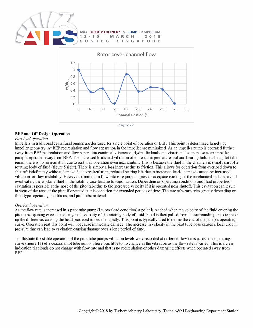
Rotor cover operation Unlike the flow through impeller vanes, the flow through the rotor cover channels is neither axisymmetric nor constant as they rotate. Fluid flows through the channel primarily as it is passes the pitot tube, remaining dormant during most of the rotation. While this is difficult to measure on an operating pump it has been calculated using a steady state (frozen rotor) CFD model of a flow through pitot tube pump with a double blade pitot tube (Pump B). The mass flow rate is measured at planes placed normal to the channels at a constant radius. This can be visualized by the plotting velocity vectors normal to these planes (figure 11). The magnitude of the mass flow rate can be plotted as a function of the channel angular position showing how the flow varies as a function of position (figure 12).
Figure 11:Velocity vectors in rotor cavity channels
0.6
0.7
0.8
0.9
1
1.1
1.2
0 0.2 0.4 0.6 0.8 1 1.2 1.4
H/H
BEP
Q/QBEP
Pitot tube pump capacity curve
Pump A Pump B Pump C
0°
Copyright© 2018 by Turbomachinery Laboratory, Texas A&M Engineering Experiment Station
Figure 12:
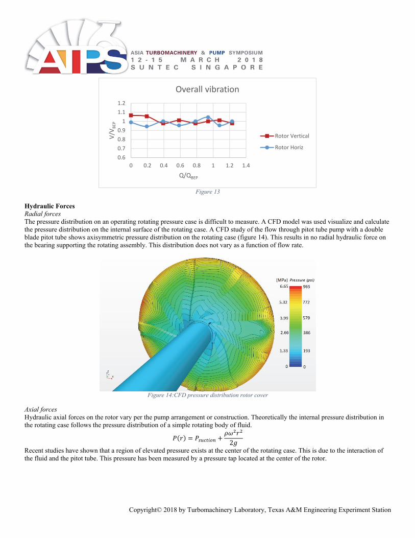
BEP and Off Design Operation Part load operation Impellers in traditional centrifugal pumps are designed for single point of operation or BEP. This point is determined largely by impeller geometry. At BEP recirculation and flow separation in the impeller are minimized. As an impeller pump is operated further away from BEP recirculation and flow separation continually increase. Hydraulic loads and vibration also increase as an impeller pump is operated away from BEP. The increased loads and vibration often result in premature seal and bearing failures. In a pitot tube pump, there is no recirculation due to part load operation even near shutoff. This is because the fluid in the channels is simply part of a rotating body of fluid (figure 5 right). There is simply a loss increase due to friction. This allows for operation from overload down to shut off indefinitely without damage due to recirculation, reduced bearing life due to increased loads, damage caused by increased vibration, or flow instability. However, a minimum flow rate is required to provide adequate cooling of the mechanical seal and avoid overheating the working fluid in the rotating case leading to vaporization. Depending on operating conditions and fluid properties cavitation is possible at the nose of the pitot tube due to the increased velocity if it is operated near shutoff. This cavitation can result in wear of the nose of the pitot if operated at this condition for extended periods of time. The rate of wear varies greatly depending on fluid type, operating conditions, and pitot tube material. Overload operation As the flow rate is increased in a pitot tube pump (i.e. overload condition) a point is reached when the velocity of the fluid entering the pitot tube opening exceeds the tangential velocity of the rotating body of fluid. Fluid is then pulled from the surrounding areas to make up the difference, causing the head produced to decline rapidly. This point is typically used to define the end of the pump’s operating curve. Operation past this point will not cause immediate damage. The increase in velocity in the pitot tube nose causes a local drop in pressure that can lead to cavitation causing damage over a long period of time. To illustrate the stable operation of the pitot tube pumps vibration levels were recorded at different flow rates across the operating curve (figure 13) of a coaxial pitot tube pump. There was little to no change in the vibration as the flow rate is varied. This is a clear indication that loads do not change with flow rate and that is no recirculation or other damaging effects when operated away from BEP.
0
0.2
0.4
0.6
0.8
1
1.2
0 40 80 120 160 200 240 280 320 360
ṁ/ṁ
max
Channel Postion (°)
Rotor cover channel flow
Copyright© 2018 by Turbomachinery Laboratory, Texas A&M Engineering Experiment Station
Figure 13
Hydraulic Forces Radial forces The pressure distribution on an operating rotating pressure case is difficult to measure. A CFD model was used visualize and calculate the pressure distribution on the internal surface of the rotating case. A CFD study of the flow through pitot tube pump with a double blade pitot tube shows axisymmetric pressure distribution on the rotating case (figure 14). This results in no radial hydraulic force on the bearing supporting the rotating assembly. This distribution does not vary as a function of flow rate.
Figure 14:CFD pressure distribution rotor cover
Axial forces Hydraulic axial forces on the rotor vary per the pump arrangement or construction. Theoretically the internal pressure distribution in the rotating case follows the pressure distribution of a simple rotating body of fluid.
2
Recent studies have shown that a region of elevated pressure exists at the center of the rotating case. This is due to the interaction of the fluid and the pitot tube. This pressure has been measured by a pressure tap located at the center of the rotor.
0.6
0.7
0.8
0.9
1
1.1
1.2
0 0.2 0.4 0.6 0.8 1 1.2 1.4
V/V
BEP
Q/QBEP
Overall vibration
Rotor Vertical
Rotor Horiz
Copyright© 2018 by Turbomachinery Laboratory, Texas A&M Engineering Experiment Station
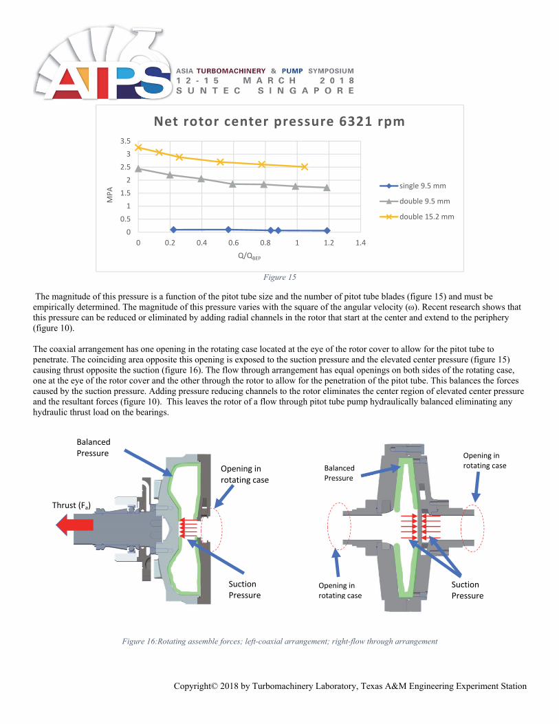
Figure 15
The magnitude of this pressure is a function of the pitot tube size and the number of pitot tube blades (figure 15) and must be empirically determined. The magnitude of this pressure varies with the square of the angular velocity (ω). Recent research shows that this pressure can be reduced or eliminated by adding radial channels in the rotor that start at the center and extend to the periphery (figure 10). The coaxial arrangement has one opening in the rotating case located at the eye of the rotor cover to allow for the pitot tube to penetrate. The coinciding area opposite this opening is exposed to the suction pressure and the elevated center pressure (figure 15) causing thrust opposite the suction (figure 16). The flow through arrangement has equal openings on both sides of the rotating case, one at the eye of the rotor cover and the other through the rotor to allow for the penetration of the pitot tube. This balances the forces caused by the suction pressure. Adding pressure reducing channels to the rotor eliminates the center region of elevated center pressure and the resultant forces (figure 10). This leaves the rotor of a flow through pitot tube pump hydraulically balanced eliminating any hydraulic thrust load on the bearings.
Figure 16:Rotating assemble forces; left-coaxial arrangement; right-flow through arrangement
0
0.5
1
1.5
2
2.5
3
3.5
0 0.2 0.4 0.6 0.8 1 1.2 1.4
MPA
Q/QBEP
Net rotor center pressure 6321 rpm
single 9.5 mm
double 9.5 mm
double 15.2 mm
Balanced Pressure
Suction Pressure
Balanced Pressure
Suction Pressure
Opening in rotating case
Thrust (Fa)
Opening in rotating case
Opening in rotating case
Copyright© 2018 by Turbomachinery Laboratory, Texas A&M Engineering Experiment Station
NPSHr in Pitot Tube Pumps Since rotor covers function differently than impellers it can be expected that they behave differently with respect to NPSHr. Since pitot tube pumps do not recirculate; they can achieve low NPSHr without the use of an inducer with stable flow characteristics across the full operating curve. Suction specific speed can be calculated for pitot tube pumps, but given that the flow in the through the rotor cover is unlike an impeller comparing the two is not valid comparison since flow instabilities do not occur at high suction specific speed pitot tube pumps. The pitot tube pump arrangement has a large effect on NPSHr. NPSHr in coaxial pitot tube pumps NPSHr in coaxial pitot tube pumps is affected by flowrate, pitot tube size, angular velocity, and the working fluid vapor pressure-temperature curve. The pitot tube penetrating the eye of the rotor cover is the major contributor to these factors.
1. Leakage at the pitot tube penetration. This leakage is a function of pitot tube size (elevated center pressure), flowrate, and speed. This leakage adds to the total flow in the rotor cover channels increasing velocity. The fluid leaking from the rotating case has been exposed to friction against the pitot tube and has a higher temperature. These both increase NPSHr.
2. The shaft supporting the pitot tube separates the suction fluid from the exiting fluid (figure 1). The fluid exiting the pitot tube is at a higher temperature than the incoming suction fluid. Heat is transferred through the wall of the pitot tube to the suction fluid.
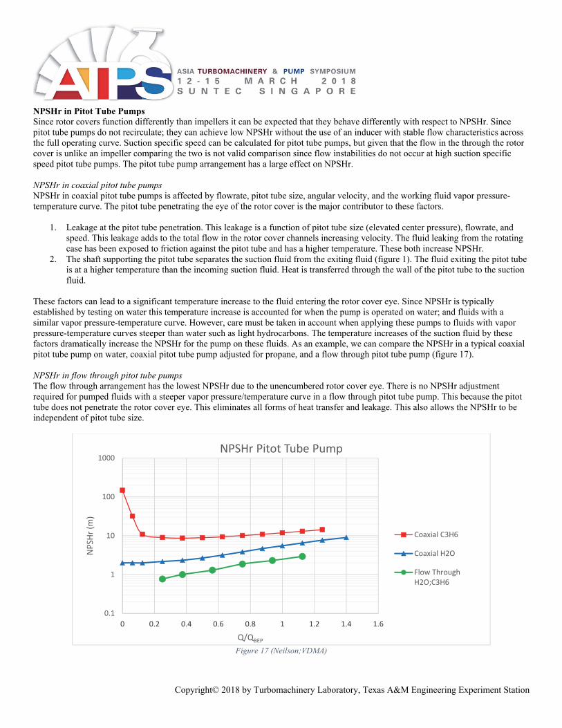
These factors can lead to a significant temperature increase to the fluid entering the rotor cover eye. Since NPSHr is typically established by testing on water this temperature increase is accounted for when the pump is operated on water; and fluids with a similar vapor pressure-temperature curve. However, care must be taken in account when applying these pumps to fluids with vapor pressure-temperature curves steeper than water such as light hydrocarbons. The temperature increases of the suction fluid by these factors dramatically increase the NPSHr for the pump on these fluids. As an example, we can compare the NPSHr in a typical coaxial pitot tube pump on water, coaxial pitot tube pump adjusted for propane, and a flow through pitot tube pump (figure 17). NPSHr in flow through pitot tube pumps The flow through arrangement has the lowest NPSHr due to the unencumbered rotor cover eye. There is no NPSHr adjustment required for pumped fluids with a steeper vapor pressure/temperature curve in a flow through pitot tube pump. This because the pitot tube does not penetrate the rotor cover eye. This eliminates all forms of heat transfer and leakage. This also allows the NPSHr to be independent of pitot tube size.
Figure 17 (Neilson;VDMA)
0.1
1
10
100
1000
0 0.2 0.4 0.6 0.8 1 1.2 1.4 1.6
NPSH
r (m
)
Q/QBEP
NPSHr Pitot Tube Pump
Coaxial C3H6
Coaxial H2O
Flow ThroughH2O;C3H6

Copyright© 2018 by Turbomachinery Laboratory, Texas A&M Engineering Experiment Station
Rotating Case Stress The rotating case consisting of the rotor and rotor cover is also the pressure containing vessel for the pump. During pump operation, the rotor sees a hydraulic pressure distribution starting at suction pressure increasing radially by the angular velocity (P(r)), in addition to the possible increased center pressure. Note that the maximum hydraulic pressure (P(r)) is never more than half the discharge pressure (Hc). The only part of the pump that is exposed to full discharge pressure is the pitot tube which is completely enclosed by the rotating case. In the event of rupture of the pitot tube the fluid is safety released into the rotating case never exposing the rotating case to discharge pressure. This gives the pump double containment of the discharge pressure. The pressure case in a pitot tube pump rotates at angular velocities up to 6000 rpm. The centrifugal forces on the rotating case itself contributes to the stress. This stress is superimposed by the stresses caused hydraulic pressure. Most modern pitot tube pumps are designed with an angled or dished rotor cover and rotor. When the rotating case is spinning the dished shape tends to flatten pulling the sides in (figure 18-right). This is intended to counter act the hydraulic forces that are pushing out reducing the overall stress in the rotating case. Consideration of rotor stresses when the pump is at rest must also be considered. In this state, all the wetted surfaces of the rotating case are exposed to whatever static pressure is present. This pushes the walls of the rotating assembly outward. Both the operating (or rotating) stress condition and non-operating (or static pressure) stress condition must be considered when applying a pitot tube pump. Using finite element analysis (FEA) of the rotating case at rest and in operation demonstrates the difference in these stress states. These images represent an exaggerated deformation for clarity.
Figure 18:Rotating assemble FEA (displacement exaggerated); left-hydrostatic pressure, not operating sides pushed out; right-spinning at 6000 rpm
sides pull in
CONCLUSION Pitot tube pumps are centrifugal pumps and as such they follow many of the same laws. However, their construction is differs from typical “impeller” centrifugal pumps and therefore they operate differently. Understanding these differences allows one to unlock their full potential when used on difficult low flow high head applications. These main differences are.
They use a rotating case to create and maintain a rotating body of fluid using enclosed channels in a rotor cover. Flow through the rotor cover channels is not axisymmetric and flow only as fluid flows through the pitot tube. Mechanical seals used to seal the rotating case are only exposed to suction pressure during operation. Although if it is
possible that they could be exposed to discharge pressure during a shut down condition it is recommended the static pressure rating exceeds discharge pressure.
Rotor cover channels do not recirculate when operated at part load. Loads on bearings resulting from hydraulic loads are light or zero and do not vary as a function of flow rate. Pitot tube pumps can be operated from shut off past the end of curve without damage or decreased bearing life. NPSHr adjustment can be required for coaxial pitot tube pumps, but is not required for flow through pitot tube pumps. The rotating case is never exposed to more than half the discharge pressure during operation. The high-pressure pitot tube is
completely enclosed in the rotating case providing a failsafe containment. If the pitot tube fails the pump no longer produces pressure above half the rated discharge pressure, the pressure in the rotating case remains unchanged.
Copyright© 2018 by Turbomachinery Laboratory, Texas A&M Engineering Experiment Station
NOMENCLATURE g = gravity (L/t2) Ha = actual pump head (L) Hc = centrifugal head (L) Hth = theoretical pump head (L) Hv = velocity head (L) hd = pitot tube drag (L) hf = friction loss (L) hs = slip (L) kf = friction coefficient (-) ks = slip coefficient (-) ṁ = mass flow rate (m/t) ṁmax = maximum mass flow rate (m/t) nq = specific speed (rpm) Suction = suction pressure (F/L2) P(r) = centrifugal pressure (F/L2) Pump A = Roto-jet® RO; 400 mm rotor; Double 9.5 mm pitot tube. Pump B = Roto-jet® RO-FT, 400 mm rotor; Double 9.5 mm pitot tube. Pump C = Roto-jet® 2200; 400 mm rotor; Double 9.5 mm pitot tube. Q = flow rate (L3/t) QBEP = BEP flow rate (L3/t) Qend = end of curve flow rate (L3/t) r = radius (L) τ = torque (L*F) τmax = maximum torque (L*F) ω = angular momentum (1/t)
REFERENCES Angle, T. L., Roudnev, A. S., & Shaw, J. G. (n.d.). Tutorial on Special Purpose Pumps - Pitot; Progressing Cavity; Air Operatied
Diaphragm; and Hydraulically Actuated Diaphragm. 14th International Pump Users Symposium (pp. 144-149). Houston, Texas: Turbomachinery Laboratory.
Erikson, J. W., & H., G. W. (1974). A New Pump for the Industry-The Roto-Jet. ASME Mechanical Engineering Conference. Dallas, Texas: ASME.
Gulich, J. F. (2013). Centrifugal Pumps. (4. edition, Ed.) New York: Springer. Karassik, I. J., Messina, J. P., Cooper, P., & Heald, C. C. (2008). Pump HandBook, 4th Edition. New York: McGraw-Hill. Neilson, B. (2016). Improvements in pitot tube pump technology. 3rd International Rotating Equipment Conference (pp. 311-322).
Dusseldorf, Germany: VDMA. Stepanoff, A. (1957). Centrifugal and Axial Flow Pumps. New York: Wiley.