Embed Size (px)
Citation preview
Facolta di Ingegneria
Dottorato di Ricerca in Ingegneria Informatica ed AutomaticaXXIII Ciclo
Dipartimento di Informatica e Sistemistica
A standard path towards scalable
conferencing in the Internet
Alessandro Amirante
Ph.D. Thesis
Tutor CoordinatorProf. Simon Pietro Romano Prof. Francesco Garofalo
Co-tutorProf. Henning Schulzrinne
November 2010
Abstract
The work described in this Ph.D. thesis has been carried out within the con-text of computer networks and real-time multimedia applications over theInternet. Specifically, we focus on conferencing, a challenging service whichexperienced a wide growth during the last years. We examine the standard-ization efforts conducted in this field by the Internet Engineering Task Force(IETF), which are mainly focused on centralized conferencing as defined bythe XCON Working Group. We actively contributed to such efforts by de-signing and implementing the defined framework and protocols, while alsowriting best current practice documents which are on the path to become Re-quest For Comments (RFCs). The main outcome of such activities has beenMeetecho, a standards-compliant multimedia conferencing and collaborationplatform we developed. Meetecho has been conceived at the outset to be ex-tensible towards a distributed architecture, yet being fully compliant withthe XCON specification, in order to better fulfill scalability requirements re-sulting from its large-scale deployment. The distributed architecture, whichis the subject of the DCON (Distributed Conferencing) proposal we submit-ted to the IETF, is thoroughly described herein, where we also provide thereader with the results of a scalability analysis we conducted in order to as-sess the actual performance improvement attainable with distribution. Thefigures obtained have been encouraging and definitely motivated us in push-ing our proposal into the Internet standardization community. Finally, aremarkable part of this dissertation is focused on diagnosing and address-ing issues that might arise when deploying multimedia architectures in theactual Internet.

Contents
1 Multimedia Conferencing 11.1 Introduction . . . . . . . . . . . . . . . . . . . . . . . . . . . . 11.2 Background . . . . . . . . . . . . . . . . . . . . . . . . . . . . 11.3 SIPPING Conferencing Framework . . . . . . . . . . . . . . . 3
1.3.1 Overview of the architectural model . . . . . . . . . . . 41.4 XCON: Centralized Conferencing . . . . . . . . . . . . . . . . 6
1.4.1 Framework . . . . . . . . . . . . . . . . . . . . . . . . 71.4.2 Dedicated protocols . . . . . . . . . . . . . . . . . . . . 8
2 Meetecho: a standard multimedia conferencing architecture 102.1 Introduction . . . . . . . . . . . . . . . . . . . . . . . . . . . . 102.2 Design . . . . . . . . . . . . . . . . . . . . . . . . . . . . . . . 102.3 Implementation . . . . . . . . . . . . . . . . . . . . . . . . . . 11
2.3.1 Server side components . . . . . . . . . . . . . . . . . . 132.3.2 Client side components . . . . . . . . . . . . . . . . . . 172.3.3 An example of client-server interaction . . . . . . . . . 20
2.4 Additional functionality . . . . . . . . . . . . . . . . . . . . . 222.4.1 Whiteboarding and polling . . . . . . . . . . . . . . . . 222.4.2 Slides sharing . . . . . . . . . . . . . . . . . . . . . . . 232.4.3 Desktop sharing . . . . . . . . . . . . . . . . . . . . . . 232.4.4 Session recording . . . . . . . . . . . . . . . . . . . . . 24
3 Towards scalable conferencing: the MEDIACTRL approach 263.1 Introduction . . . . . . . . . . . . . . . . . . . . . . . . . . . . 263.2 Media Server Control . . . . . . . . . . . . . . . . . . . . . . . 27
3.2.1 Application Server: the brain . . . . . . . . . . . . . . 293.2.2 Media Server: the arm . . . . . . . . . . . . . . . . . . 30
3.3 An open-source implementation . . . . . . . . . . . . . . . . . 313.3.1 Application Server: Asterisk . . . . . . . . . . . . . . . 323.3.2 Media Server: Confiance VideoMixer . . . . . . . . . . 32
3.4 Use Case Scenarios . . . . . . . . . . . . . . . . . . . . . . . . 35
CONTENTS iv
3.4.1 Direct Echo Test . . . . . . . . . . . . . . . . . . . . . 363.4.2 Echo Test based on Recording . . . . . . . . . . . . . . 38
3.5 MEDIACTRL in Meetecho . . . . . . . . . . . . . . . . . . . . 44
4 DCON: a scalable distributed conferencing framework 454.1 Introduction . . . . . . . . . . . . . . . . . . . . . . . . . . . . 454.2 Framework requirements . . . . . . . . . . . . . . . . . . . . . 464.3 Design . . . . . . . . . . . . . . . . . . . . . . . . . . . . . . . 47
4.3.1 DCON framework . . . . . . . . . . . . . . . . . . . . . 474.4 Implementation . . . . . . . . . . . . . . . . . . . . . . . . . . 48
4.4.1 Inter-focus interaction . . . . . . . . . . . . . . . . . . 50
5 From theory to practice: a scalability analysis 585.1 Preliminary considerations . . . . . . . . . . . . . . . . . . . . 58
5.1.1 The BFCP stresser . . . . . . . . . . . . . . . . . . . . 595.2 Stressing the Application Server . . . . . . . . . . . . . . . . . 60
5.2.1 Centralized scenario . . . . . . . . . . . . . . . . . . . 605.2.2 Distributed scenario . . . . . . . . . . . . . . . . . . . 62
5.3 Involving the Media Server . . . . . . . . . . . . . . . . . . . . 635.3.1 Centralized scenario . . . . . . . . . . . . . . . . . . . 635.3.2 Distributed scenario . . . . . . . . . . . . . . . . . . . 655.3.3 Comparative analysis . . . . . . . . . . . . . . . . . . . 66
5.4 Involving the Floor Control Server . . . . . . . . . . . . . . . 685.4.1 Centralized scenario . . . . . . . . . . . . . . . . . . . 695.4.2 Distributed scenario . . . . . . . . . . . . . . . . . . . 70
5.5 Considerations . . . . . . . . . . . . . . . . . . . . . . . . . . 73
6 Troubleshooting 746.1 Introduction . . . . . . . . . . . . . . . . . . . . . . . . . . . . 746.2 Issues . . . . . . . . . . . . . . . . . . . . . . . . . . . . . . . 74
6.2.1 Signaling plane . . . . . . . . . . . . . . . . . . . . . . 746.2.2 Media plane . . . . . . . . . . . . . . . . . . . . . . . . 766.2.3 Proxy/Firewall traversal . . . . . . . . . . . . . . . . . 76
6.3 DYSWIS: A distributed approach to network diagnosis . . . . 776.3.1 Architecture . . . . . . . . . . . . . . . . . . . . . . . . 776.3.2 Diagnosing SIP/RTP faults . . . . . . . . . . . . . . . 786.3.3 Case study: one-way media issue . . . . . . . . . . . . 806.3.4 Implementation details . . . . . . . . . . . . . . . . . . 92
6.4 Meetecho tunneling solution . . . . . . . . . . . . . . . . . . . 946.4.1 Transport . . . . . . . . . . . . . . . . . . . . . . . . . 986.4.2 Protocols Handling . . . . . . . . . . . . . . . . . . . . 101

CONTENTS v
6.4.3 Experimentations . . . . . . . . . . . . . . . . . . . . . 103
7 Conclusions 109

Chapter 1
Multimedia Conferencing
1.1 Introduction
Conferencing can nowadays be considered by providers as an extremely chal-
lenging service, since it imposes a number of stringent requirements to the
underlying network infrastructure. First, the intrinsic multimedia nature
of a conference (which typically involves a combination of audio, video, in-
stant messaging, desktop sharing, etc.) requires coping with complex issues
like session management and floor control. Second, the real-time features of
conference-based communication call for an appropriate level of Quality of
Service (QoS). This chapter presents the reader with standardization pro-
cess associated with multimedia conferencing over IP the main international
standardization bodies are fostering.
1.2 Background
The most widespread signaling protocol for IP networks is the Session Ini-
tiation Protocol (SIP) [30]. It provides users with the capability to initiate,
manage, and terminate communication sessions. SIP natively allows multi-
party calls among multiple parties. However, conferencing does represent a
more sophisticated service that can be seen as an extension of multi-party
calls where audio is just one of the possible media involved. For example,
the conferencing service may provide video functionality as well as instant

Background 2
messaging, files and presentations sharing or even gaming. Furthermore, the
conferencing service provides the means for a user to create, manage, termi-
nate, join and leave conferences. Finally, it provides the network with the
ability to deliver information about these conferences to the involved parties.
Over the last few years, standardization efforts have been devoted to confer-
encing related matters by international bodies like the IETF and the 3GPP.
The Internet Engineering Task Force (IETF) is an open international commu-
nity concerned with the evolution of the Internet architecture and protocols.
Within the IETF, the Centralized Conferencing (XCON) working group is ex-
plicitly focusing on multimedia conferencing. Furthermore, there is another
working group whose standardization activity also dealt with conferencing
related issues: the Session Initiation Proposal Investigation (SIPPING) WG.
It developed the very first framework for multi-party conferencing based on
the SIP protocol [27]. This framework defines a general architectural model,
presents terminology, and explains how SIP is involved in a tightly coupled
conference. It is the subject of Section 1.3. Taking inspiration from the work
carried out in SIPPING and willing to release any constraint about the sig-
naling protocol, the XCON WG worked hard on the definition of both a
reference framework [5] and a data model [21] for tightly coupled conference
scenarios, which are described in Section 1.4.
The 3rd Generation Partnership Project (3GPP) actually represents a
collaboration agreement among a number of regional standard bodies, born
with the main objective of developing Technical Specifications for a third-
generation mobile system based on GSM. Recently, the 3GPP has worked on
the specification of a tightly-coupled conferencing service. Both the require-
ments and the architecture for such a service have been defined [1]. The cited
document indeed represents a sort of integrated specification within the IMS,
aimed at harmonizing the combined use of existing standard protocols, like
the Session Initiation Protocol (SIP), SIP Events, the Session Description
Protocol (SDP) and the Binary Floor Control Protocol (BFCP).
SIPPING Conferencing Framework 3
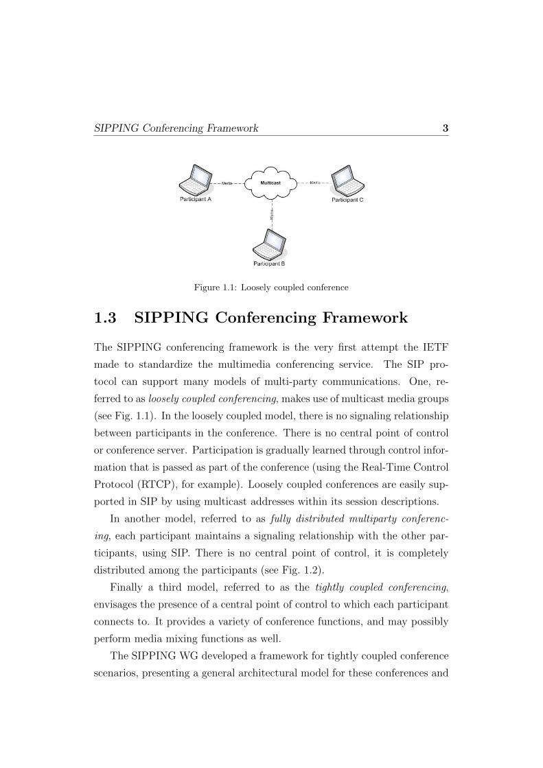
Figure 1.1: Loosely coupled conference
1.3 SIPPING Conferencing Framework
The SIPPING conferencing framework is the very first attempt the IETF
made to standardize the multimedia conferencing service. The SIP pro-
tocol can support many models of multi-party communications. One, re-
ferred to as loosely coupled conferencing, makes use of multicast media groups
(see Fig. 1.1). In the loosely coupled model, there is no signaling relationship
between participants in the conference. There is no central point of control
or conference server. Participation is gradually learned through control infor-
mation that is passed as part of the conference (using the Real-Time Control
Protocol (RTCP), for example). Loosely coupled conferences are easily sup-
ported in SIP by using multicast addresses within its session descriptions.
In another model, referred to as fully distributed multiparty conferenc-
ing, each participant maintains a signaling relationship with the other par-
ticipants, using SIP. There is no central point of control, it is completely
distributed among the participants (see Fig. 1.2).
Finally a third model, referred to as the tightly coupled conferencing,
envisages the presence of a central point of control to which each participant
connects to. It provides a variety of conference functions, and may possibly
perform media mixing functions as well.
The SIPPING WG developed a framework for tightly coupled conference
scenarios, presenting a general architectural model for these conferences and

SIPPING Conferencing Framework 4
Figure 1.2: Fully distributed multiparty conference
Figure 1.3: Tightly coupled conference
discussing the ways in which SIP itself is involved.
1.3.1 Overview of the architectural model
The central component introduced in the SIPPING architectural model is
called focus, and maintains a SIP signaling relationship with each participant
in the conference. The result is a star topology, as depicted in Fig. 1.3.
The focus is responsible for making sure that the media streams that
constitute the conference are available to the participants in the conference.
It does that through the use of one or more mixers, each of which combines a
number of input media streams to produce one or more output media streams.
The focus uses the media policy to determine the proper configuration of the
mixers and has access to the conference policy, an instance of which exists
SIPPING Conferencing Framework 5
for each conference. Effectively, the conference policy can be thought of
as a database that describes the way the conference should operate. It is
responsibility of the focus to enforce those policies. Not only does the focus
need read access to the database, but it needs to know when it has changed.
Such changes might result in SIP signaling (for example, the ejection of
a user from the conference using BYE), and those changes that affect the
conference state will require a notification to be sent to subscribers using the
conference notification service. The conference is represented by a URI that
identifies the focus. Each conference has a unique focus and a unique URI
identifying that focus. Requests to the conference URI are routed to the focus
responsible for that specific conference. Users usually join the conference by
sending an INVITE to the conference URI. As long as the conference policy
allows, the INVITE is accepted by the focus and the user is brought into the
conference. Users can leave the conference by sending a BYE, as they would in
a normal call. Similarly, the focus can terminate a dialog with a participant,
should the conference policy change to indicate that the participant is no
longer allowed in the conference. A focus can also initiate an INVITE to
bring a participant into the conference. The notion of a conference-unaware
participant is important in this framework. A conference-unaware participant
does not even know that the User Agent (UA) it is communicating with
happens to be a focus. As far as it is concerned, it appears like any other
UA. The focus, of course, is aware of its duties, and performs the tasks needed
for the conference to operate. Conference-unaware participants have access
to a good deal of functionality. They can join and leave conferences using SIP,
and obtain more advanced features through stimulus signaling. However, if
the participant wishes to explicitly control aspects of the conference using
functional signaling protocols, it must be conference-aware. A conference-
aware participant is one that has access to advanced functionality through
additional protocol interfaces, which may include access to the conference
policy through non-SIP-specific mechanisms. The participant can interact
with the focus using extensions, such as REFER, in order to access enhanced

XCON: Centralized Conferencing 6
call control functions. The participant can SUBSCRIBE to the conference URI,
and be connected to the conference notification service provided by the focus.
Through this mechanism, it can learn about changes in participants, the
state of the dialogs and the media. The participant can communicate with
the conference policy server using some kind of non-SIP-specific mechanism
by which it can affect the conference policy. The interfaces between the
focus and the conference policy, and between the conference policy server
and the conference policy are non-SIP-specific. For the purposes of SIP-
based conferencing, they serve as logical roles involved in a conference, as
opposed to representing a physical decomposition.
1.4 XCON: Centralized Conferencing
The purpose of the XCONWorking Group and its framework is to achieve in-
teroperability between the logical entities developed by different vendors for
controlling different aspects of advanced conferencing applications. The SIP-
PING Conferencing Framework described in the previous section provides
an overview of a wide range of centralized conferencing solutions known to-
day in the industry. The logical entities and the listed scenarios are used to
illustrate how SIP can be used as a signaling means in these conferencing
systems. The SIPPING Conferencing Framework does not define new con-
ference control protocols to be used by the general conferencing system and
uses only basic SIP, the SIP conferencing call control features [16], and the
SIP Conference Package [31] for simple SIP conferencing realization. On the
other hand, the centralized conferencing framework specified by the XCON
WG defines a particular centralized conferencing system and the logical enti-
ties implementing it. It also defines a particular data model and refers to the
set of protocols (beyond call signaling means) to be used among the logical
entities for implementing advanced conferencing features.

XCON: Centralized Conferencing 7
1.4.1 Framework
The XCON framework extends the SIPPING model by making it indepen-
dent from the signaling protocol employed, while following the same prin-
ciples and adopting the same terminology. Hence, the conference scenarios
supported are tightly coupled conferences. In addition to the basic features, a
conferencing system supporting the XCON model can offer richer functional-
ity, by including dedicated conferencing applications with explicitly defined
capabilities, along with providing the standard protocols for managing and
controlling the different attributes of these conferences.
The centralized conferencing system proposed by the XCON framework
is built around a fundamental concept of a conference object. A conference
object provides the data representation of a conference during each of the
various stages it goes through (e.g., creation, reservation, active, completed,
etc.). It is accessed via the logical functional elements, with whom a con-
ferencing client interfaces, using the various protocols identified in Fig. 1.4.
Such functional elements are a Conference Control Server, Floor Control
Server, any number of Foci, and a Notification Service. A Conference Con-
trol Protocol (CCP) provides the interface between a conference and media
control client and the conference control server. For such purpose, the work-
ing group is specifying a dedicated protocol called Centralized Conferencing
Manipulation Protocol (CCMP), which is briefly introduced in Section 1.4.2.
A floor control protocol, instead, provides the interface between a floor con-
trol client and the floor control server. Section 1.4.2 touches on how the
Binary Floor Control Protocol provides such feature. A call signaling pro-
tocol (e.g., SIP, H.323, Jabber, Q.931, ISUP, etc.) provides the interface
between a call signaling client and a focus, while a notification protocol (e.g.,
SIP Notify [23]) provides the interface between the conferencing client and
the notification service. A conferencing system can support a subset of the
conferencing functions depicted in Fig. 1.4. However, there are some essential
components that would typically be used by most other advanced functions,
such as the notification service. For example, the notification service is used

XCON: Centralized Conferencing 8
Figure 1.4: XCON framework logical decomposition
to correlate information, such as the list of participants with their media
streams, between the various other components.
1.4.2 Dedicated protocols
Conference management
The latest output of the XCON WG is a protocol for the management and
manipulation of the conference object: the Centralized Conferencing Manip-
ulation Protocol (CCMP) [6]. CCMP is a stateless, XML-based, client-server
protocol carrying in its request and response messages conference informa-
tion. It represents a powerful means to control basic and advanced conference
features such as conference state and capabilities, participants and relative
roles and details. It allows authenticated and authorized users to create, ma-
nipulate and delete conference objects. Operations on conferences include
adding and removing participants, changing their roles, as well as adding
and removing media streams and associated end points. CCMP is based on

XCON: Centralized Conferencing 9
a client-server paradigm and is specifically suited to serve as a conference
manipulation protocol within the XCON framework, with the Conference
Control Client and Conference Control Server acting as client and server, re-
spectively. The CCMP uses HTTP as the protocol to transfer requests and
responses, which contain the domain-specific XML-encoded data objects de-
fined in the XCON data model [21].
Floor control
Floor control is a way to handle moderation of resources in a conference. In
fact, a floor can be seen, from a logical point of view, as the right to ac-
cess and/or manipulate a specific set of resources that might be available to
end-users. Introducing means to have participants request such a right is
what is called “floor control”. A typical example is a lecture mode confer-
ence, in which interested participants might need to ask the lecturer for the
right to talk in order to ask a question. The Binary Floor Control Protocol
(BFCP) [10] has been standardized by the IETF for such purpose. This pro-
tocol envisages the above mentioned floor as a token that can be associated
with one or more resources. Queues and policies associated with such floors
are handled by a Floor Control Server (FCS), which acts as a centralized
node for all requests coming from Floor Control Participants (FCP). Deci-
sions upon incoming requests (e.g., accepting or denying requests for a floor)
can be either taken on the basis of automated policies by the FCS itself, or
relayed to a Floor Control Chair (FCC), in case one has been assigned to the
related floor. These decisions affect the state of the queues associated with
the related floors, and consequently the state of the resources themselves.
Considering again the lecture mode scenario example presented before, a
participant who has been granted the floor (i.e., the right to ask a question
to the lecturer) would be added to the conference mix, whereas participants
without the floor (or with pending requests) would be excluded from the
same mix, thus being muted in the conference.
Chapter 2
Meetecho: a standardmultimedia conferencingarchitecture
2.1 Introduction
In this chapter we present a conferencing architecture called Meetecho. To
the purpose, we embrace a practical approach, by describing an actual imple-
mentation of an open source centralized video-conferencing system capable
to offer advanced communication experience to end-users through the effec-
tive exploitation of mechanisms like session management and floor control.
Meetecho has been designed to be fully compliant with the latest standard
proposals coming from both the IETF and the 3GPP and can be consid-
ered as an outstanding example of a real-time application built on top of the
grounds paved by the SIP protocol. We will discuss both the design of the
overall conferencing framework and the most important issues we had to face
during the implementation phase.
2.2 Design
We started our design from an architectural perspective of the service we
wanted to achieve, that is an advanced conferencing application. The first
step was obviously identifying and locating all the logical elements which

Implementation 11
would be involved in the above mentioned scenario. We then investigated
the possibility of replicating, or at least replacing, such elements with existing
real-world components.
First of all, the scenario clearly addresses two distinct roles, a server side
(the elements providing the service) and a client side (all users accessing
the service). We referred to these roles in identifying the elements. At the
client side, the very first mandatory element that comes into play is the User
Equipment (UE), which has to be both SIP-compliant and XCON-enabled
in order to correctly support conferencing. On the server side, instead, we
identified different cooperating components: the Application Server (AS),
the Media Server (MS) and one or more Gateways. The former can be fur-
ther split into subcomponents, as it has to provide several functionality like
dealing with the signaling plane of the conferencing scenario, handling the
management of conferences (e.g., creating, modifying, deleting them), and
in general taking care of all the business logic, which includes policies, re-
lated to the scenario. These policies include Floor Control, which implies
that the AS will have to also manage access rights to shared resources in our
conferencing framework. The media streams are manipulated and provided
by the Media Server. It has to provide the resources, by offering function-
ality like mixing of incoming media streams (in our case, audio and video
streams) and media stream processing (e.g., audio transcoding, media anal-
ysis). Finally, considering the XCON framework is conceived to be agnostic
with respect to the signaling protocol used to access the service, specific el-
ements are needed as gateways towards other technologies. For instance, a
Gateway is needed in order to guarantee the interworking with the Public
Switched Telephone Network (PSTN).
2.3 Implementation
As already introduced in Chapter 1, the XCON framework defines a suite of
conferencing protocols, which are meant as complementary to the call signal-
ing protocols, for building advanced conferencing applications and achieving
Implementation 12
Participant
(Client)
Focus
(Server)
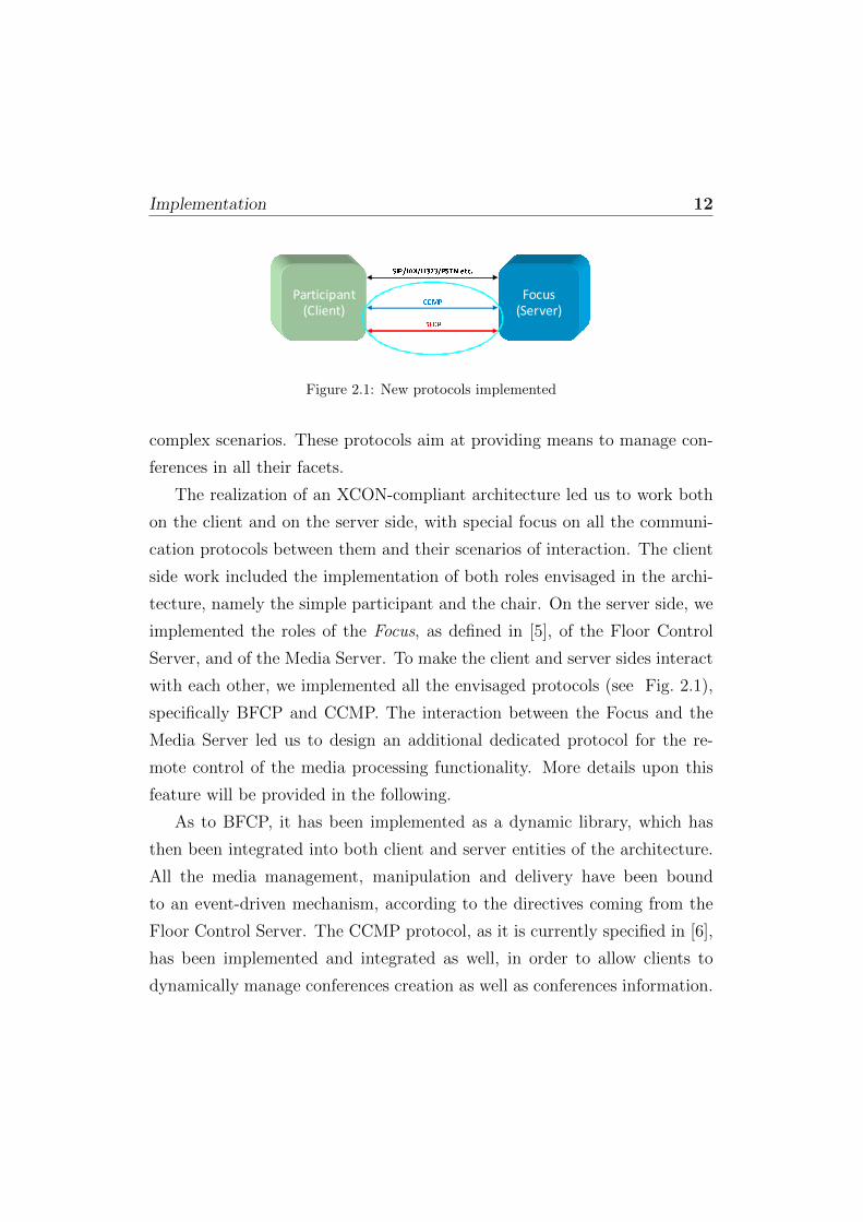
SIP/IAX/H323/PSTN etc.CCMPBFCPFigure 2.1: New protocols implemented
complex scenarios. These protocols aim at providing means to manage con-
ferences in all their facets.
The realization of an XCON-compliant architecture led us to work both
on the client and on the server side, with special focus on all the communi-
cation protocols between them and their scenarios of interaction. The client
side work included the implementation of both roles envisaged in the archi-
tecture, namely the simple participant and the chair. On the server side, we
implemented the roles of the Focus, as defined in [5], of the Floor Control
Server, and of the Media Server. To make the client and server sides interact
with each other, we implemented all the envisaged protocols (see Fig. 2.1),
specifically BFCP and CCMP. The interaction between the Focus and the
Media Server led us to design an additional dedicated protocol for the re-
mote control of the media processing functionality. More details upon this
feature will be provided in the following.
As to BFCP, it has been implemented as a dynamic library, which has
then been integrated into both client and server entities of the architecture.
All the media management, manipulation and delivery have been bound
to an event-driven mechanism, according to the directives coming from the
Floor Control Server. The CCMP protocol, as it is currently specified in [6],
has been implemented and integrated as well, in order to allow clients to
dynamically manage conferences creation as well as conferences information.
Implementation 13
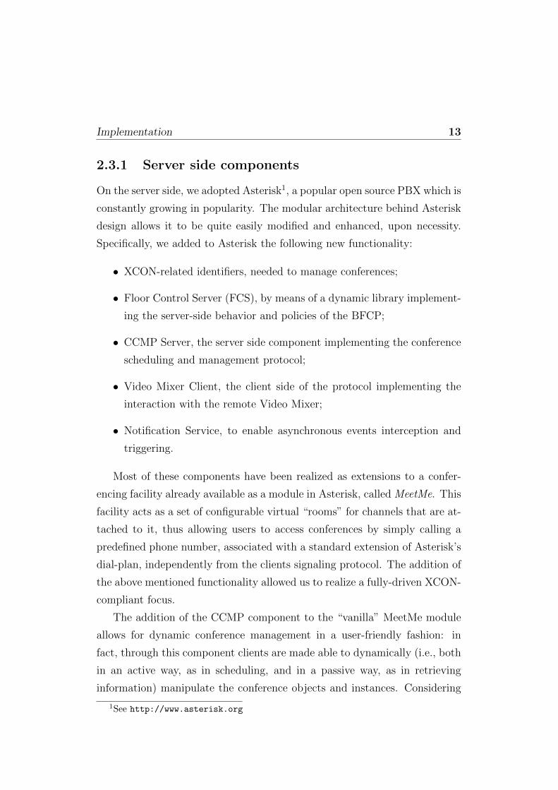
2.3.1 Server side components
On the server side, we adopted Asterisk1, a popular open source PBX which is
constantly growing in popularity. The modular architecture behind Asterisk
design allows it to be quite easily modified and enhanced, upon necessity.
Specifically, we added to Asterisk the following new functionality:
• XCON-related identifiers, needed to manage conferences;
• Floor Control Server (FCS), by means of a dynamic library implement-
ing the server-side behavior and policies of the BFCP;
• CCMP Server, the server side component implementing the conference
scheduling and management protocol;
• Video Mixer Client, the client side of the protocol implementing the
interaction with the remote Video Mixer;
• Notification Service, to enable asynchronous events interception and
triggering.
Most of these components have been realized as extensions to a confer-
encing facility already available as a module in Asterisk, called MeetMe. This
facility acts as a set of configurable virtual “rooms” for channels that are at-
tached to it, thus allowing users to access conferences by simply calling a
predefined phone number, associated with a standard extension of Asterisk’s
dial-plan, independently from the clients signaling protocol. The addition of
the above mentioned functionality allowed us to realize a fully-driven XCON-
compliant focus.
The addition of the CCMP component to the “vanilla” MeetMe module
allows for dynamic conference management in a user-friendly fashion: in
fact, through this component clients are made able to dynamically (i.e., both
in an active way, as in scheduling, and in a passive way, as in retrieving
information) manipulate the conference objects and instances. Considering
1See http://www.asterisk.org

Implementation 14
the dynamic nature of the framework with respect to policies, settings and
scheduled conferences, all the required changes in the dial-plan, as well as
dynamic reloading upon necessity, have been accomplished by adding the
related functionality to the extended MeetMe module.
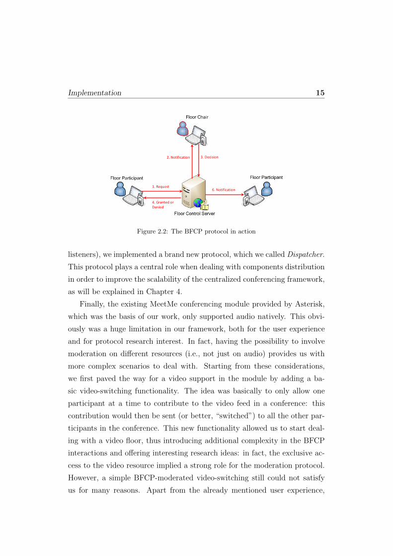
For what concerns BFCP, we had to implement the entire protocol, as
well as its behavior which includes queues and state machines, from scratch.
In order to achieve this, BFCP has been realized as a dynamic library, which
is loaded at run time by the Asterisk server and comes into play whenever
a resource is to be moderated. In fact, Asterisk, as the entity in charge
of the business logic, also acts as the Floor Control Server of the architec-
ture (see Fig. 2.2). The FCS functionality is involved every time a request
is generated from a participant, asking for the right to access a specific re-
source (e.g., audio or video). As suggested by the picture, the FCS itself
may or may not take any decision about incoming requests. In fact, while
automated policies may be involved to take care of floor control in a more
straightforward approach (e.g., to always accept or refuse incoming requests
according to predefined policies), if they are not specified the FCS rather
forwards floor requests to the designated floor chair, who is in charge of tak-
ing a decision that is accordingly notified to all the interested parties. As
a transport method for BFCP messages, support for both TCP/BFCP and
TCP/TLS/BFCP has been implemented. Besides, since conference-aware
participants need to know all the BFCP-related information of a conference
in order to take advantage of the BFCP functionality, the focus needs means
to provide her/him with such details. Apart from any out-of-band mechanism
that could be exploited, the IETF has standardized a way [9] to encapsulate
this information within the context of an SDP (Session Description Proto-
col) offer/answer. This functionality has been implemented as well in the
module.
We implemented a Notification Service by exploiting both existing solu-
tions and customized modules. Besides reusing the already available Asterisk
Manager Interface (which however only allows active notifications to passive
Implementation 15
1. Request
2. Notification 3. Decision
4. Granted or
Denied
6. Notification
Figure 2.2: The BFCP protocol in action
listeners), we implemented a brand new protocol, which we called Dispatcher.
This protocol plays a central role when dealing with components distribution
in order to improve the scalability of the centralized conferencing framework,
as will be explained in Chapter 4.
Finally, the existing MeetMe conferencing module provided by Asterisk,
which was the basis of our work, only supported audio natively. This obvi-
ously was a huge limitation in our framework, both for the user experience
and for protocol research interest. In fact, having the possibility to involve
moderation on different resources (i.e., not just on audio) provides us with
more complex scenarios to deal with. Starting from these considerations,
we first paved the way for a video support in the module by adding a ba-
sic video-switching functionality. The idea was basically to only allow one
participant at a time to contribute to the video feed in a conference: this
contribution would then be sent (or better, “switched”) to all the other par-
ticipants in the conference. This new functionality allowed us to start deal-
ing with a video floor, thus introducing additional complexity in the BFCP
interactions and offering interesting research ideas: in fact, the exclusive ac-
cess to the video resource implied a strong role for the moderation protocol.
However, a simple BFCP-moderated video-switching still could not satisfy
us for many reasons. Apart from the already mentioned user experience,
Implementation 16
which could surely benefit from approaches like grid-based video layouts,
video-switching, as the name suggests, is a simple blind forwarding of frames
coming from a source to one or several destinations. This means that it is
in no way concerned with content adaption, which might instead be needed
when a conference involves participants making use of heterogeneous applica-
tions, devices and/or codecs. The most obvious example is two participants
making use of different video codecs (e.g., H.261 and H.263): a blind forward-
ing would prevent both participants from watching the peer’s contribution,
if available. This led us to study the possibility of designing an ad-hoc media
server which would act as a video multiplexer, for complex layouts involving
more sources, and transcoder, to deal with video streams with different en-
codings and resolutions. To achieve this goal, we designed and implemented
a custom video mixer, called Confiance VideoMixer. Considering our will to
adhere to the separation of responsibilities principle in order to foster scala-
bility, we chose this videomixer to be a remotely controllable media server.
In this way, the conferencing module would only have to deal with the appli-
cation logic (e.g., attaching participants to a mixed stream, specifying mix
layouts, and so on), while the videomixer would process and manipulate the
video streams according to directives sent by the module. This approach is
the same as the one currently fostered by the MEDIACTRL (Media Server
Control) Working Group of the IETF, and will be thoroughly examined in
Chapter 3. The MeetMe application and the external VideoMixer commu-
nicate through a dedicated channel, through which the participants’ video
streams are controlled. In the current implementation, the protocol allows
for the per-user and per-conference customization of several aspects of the
video processing, as layouts, transcoding, as well as the optional ability for
participants to watch their own contribution in the mix they receive. All
the directives the controller (in this case the conferencing module) sends to
the videomixer are event-driven, and they make part of its application logic.
Whenever a video-enabled participant joins a conference, its stream is redi-
rected to the videomixer. By properly correlating the participant’s identifiers
Implementation 17
associated with its own instances in the controller and in the videomixer, the
controller is then able to command different actions on the stream. BFCP
moderation is one of the above mentioned events that can result in an ac-
tion being requested by the controller: the video floor being granted to a
participant would have the controller request the related participant’s video
stream to be included in the overall mix, just as the same floor being denied
or revoked would result in an opposite request.
While the CCMP- and BFCP-enabled Asterisk component, empowered
with the Confiance Videomixer, provided us with the ability to handle both
media streams and signaling, moderation and conference management pro-
tocols, we still needed the ability to handle a further protocol, the eXtensible
Messaging and Presence Protocol (XMPP) [32], we chose as both the Instant
Messaging protocol and an out-of-band signaling mechanism of the frame-
work. For such purpose, we chose to make use of a popular XMPP server,
called Openfire2, which we placed side by side with Asterisk to realize the
logically centralized XCON focus. Openfire, as we will see in Chapter 4,
becomes of paramount importance when moving towards a distributed con-
ferencing architecture.
2.3.2 Client side components
On the client side, we adopted an existing open source instant messaging
client, called Spark 3, as the basis for our work. Spark is a piece of software
written in Java, which implements the XMPP protocol to realize instant mes-
saging scenarios. It is natively conceived to interact with the aforementioned
Openfire server, and is easily extensible by developing custom plugins which
implement new functionality. In our case, we introduced the support for the
SIP/SDP, RTP, BFCP and CCMP protocols, besides some additional func-
tionality that will be briefly described in Section 2.4. New graphical widgets
have been realized as well, in order to enable user-friendly support for SIP-
2See http://www.igniterealtime.org/projects/openfire/3See http://www.igniterealtime.org/projects/spark/

Implementation 18
Figure 2.3: Conference creation
and BFCP-related settings and to allow users to take advantage of the func-
tionality related to both conference scheduling and BFCP. As to conference
scheduling, Fig. 2.3 shows the widget by means of which it is possible to dy-
namically create new conferences by exploiting the CCMP protocol. Fig. 2.4,
instead, shows the list of scheduled conferences, retrieved by means of CCMP
as well.
Additionally, we implemented the client side BFCP behavior as a Java
library. An ad-hoc panel, associated with such library, has been introduced
in order to enable users to:
• Send BFCP messages to the BFCP server;
• Interactively build BFCP floor requests in a user-friendly fashion, ei-
ther in participant or in chair (i.e., with enhanced floor management
functionality) mode;
• Keep an up-to-date log of all the BFCP messages exchanged with the
server (and optionally show each such message in further detail by
simply clicking on the related entry in the history widget).

Implementation 19
Figure 2.4: List of scheduled conferences
Figure 2.5: Moderation panel
With respect to the role of the chair, we added ad-hoc interfaces in order to
enable potential moderators to either manage floor requests issued by confer-
ence participants (an example of such interfaces is shown in Figure 2.5), or
build so-called third-party floor requests, i.e., requests generated by the chair
on behalf of a different participant. It is worth noting that such functional-
ity is particularly interesting since it enables the chair to allow conference-
unaware participants to take part to an XCON-enabled conference.
Finally, as to the VoIP functionality of the client, we adopted and ex-
tended an open source SIP stack called MjSip4. To take advantage of the
already mentioned negotiation of BFCP information within the context of
the SDP offer/answer, we added the support for the encapsulation of BFCP
information in SDP bodies. In this way, the BFCP is automatically ex-
4See http://www.mjsip.org

Implementation 20
Participant
(Client)
Focus
(Server)
SIP/IAX/H323/PSTN etc.CCMPBFCPConfsRequest ConfsResponseSIP call to number 867100 (to join conference 867100)IVR-based messages (Welcome, Muted Status, etc.) SIP re-INVITE (BFCP info encapsulated in SDP body)FloorRequest FloorRequestStatus (Pending) Forward the request to the ChairChair DecisionNotify Chair Decision.
.
.
Figure 2.6: An example of signaling between client and server
ploited whenever a SIP INVITE (or re-INVITE, in case the negotiation is
involved in a subsequent moment) contains BFCP-related identifiers. Be-
sides, the appropriate transport method for the BFCP communication with
the FCS (i.e., TCP/BFCP or TCP/TLS/BFCP) is automatically chosen and
exploited with respect to this SDP negotiation.
2.3.3 An example of client-server interaction
To provide the reader with a more detailed overview of the way the client-
server interaction involves the introduced protocols, this subsection is de-
voted to presenting an example regarding a typical use case scenario. To
ease the understanding of the sequence diagram depicted in Fig. 2.6, each
protocol is represented with a different line style:
1. A participant (client in the scenario) contacts the Focus (the server),
through the CCMP protocol (dashed line), to ask for the list of cur-
rently active conferences, thus sending a ConfsRequest message request

Implementation 21
with Active as argument;
2. The Focus processes the request and sends back to the participant (still
through the CCMP protocol) a ConfsResponse message, containing the
list of all active conferences;
3. The participant reads the list and decides to join the active conference
identified by the number 8671000: to join the conference, she/he calls
the conference number – as if it were a standard phone number – using
SIP (solid line) as the call signaling protocol, thus placing a call to the
SIP URI 8671000@Focus (where Focus is the SIP domain, in this case
the IP address of the Asterisk server);
4. The Focus receives the call and, according to the specified dialplan
rules, routes it to the XCON-enabled MeetMe instance managing the
conference with the same call number;
5. The XCON-enabled MeetMe instance managing the conference, through
IVR (Interactive Voice Response), plays back a series of pre-recorded
voice messages to welcome the new user. It also warns the client about
the fact that she/he is initially muted in the conference;
6. All the relevant BFCP information is encapsulated in an SDP body,
and then sent back to the new user by means of a SIP re-INVITE;
7. Once the client receives the re-INVITE and becomes aware of the
needed BFCP set of data, she/he, using the BFCP (dotted line), de-
cides to make a FloorRequest to ask the Focus for the permission to
talk;
8. The Focus, as Floor Control Server, answers the client by sending back
a FloorRequestStatus BFCP message notifying that the request is cur-
rently pending. At the same time, the Floor Control Server forwards
the message to the chair of the requested floor as well, to ask him to
take a decision about the request.
Additional functionality 22
From this point on, the BFCP transaction proceeds exactly as described
before (see Fig. 2.2). Once the chair grants the floor, the client is un-muted
and thus given the permission to talk until the floor is not willingly released
by the client herself/himself or revoked by the chair. Since a floor is a logical
object, all BFCP transactions will proceed in the same way, independently
from the set of resources (be it audio or video, in the case of our platform) the
related floor(s) could be associated with. In case the floor request involved
a manipulation of a video request, a subsequent interaction between the
conferencing module and the remote videomixer would take place through
the dedicated channel.
2.4 Additional functionality
In this section we provide a brief overview of the additional functionality we
implemented in the Meetecho conferencing system. Most of such function-
ality have been realized by exploiting open source software programs, which
have been extended and modified to meet our requirements.
2.4.1 Whiteboarding and polling
The first additional feature we introduced in the platform is a whiteboarding
and polling tool, which allows users participating in a conferencing session
to share one or more common drawing areas and to make polls and voting.
We started from the open source tool jSummit5, making a lot of changes to
it in order to migrate from a peer to peer approach to a more suitable to us
client-server paradigm. The server side of the protocol is always hosted by the
XCON focus, while the client side has been introduced in the aforementioned
plugin for the Spark client.
5See http://jsummit.sourceforge.net

Additional functionality 23
2.4.2 Slides sharing
A feature typically requested in conferencing systems is presentation shar-
ing. This feature basically allows one of the participants, the presenter, to
share a presentation with the other participants, and to discuss its slides ac-
cordingly. A presentation might be shared in several different formats, like
Microsoft PowerPoint, Adobe PDF, Open Document Format. We dealt with
such heterogeneity of formats by considering every presentation as a simple
slideshow of static images. In fact, whenever a presentation is shared in a
conference, it is converted in background by the server to a series of images
made available on a web server together with metadata information. Be-
sides, whenever the presenter triggers a slide change, such event is notified
to the other participants by means of XMPP: information about the new
slide is provided in the notification (the slide number, the HTTP URL where
the slide can be retrieved, etc.) making it easy for the other participants to
passively attend the presentation.
2.4.3 Desktop sharing
Another functionality usually offered by conferencing systems is desktop shar-
ing. We introduced such feature in Meetecho by integrating a Java-based
open source tool called JRDesktop6. It leverages the Java Remote Method In-
vocation (RMI) mechanism in order to let clients, called Viewers, get screens
updates from the Sharing Server. Such “pull” paradigm did not seem to
us as the best solution for two reasons: (i) the Sharing Server has to han-
dle as many connection as the actual number of viewers connected, meaning
that bandwidth and resource consumption become critical and might affect
other functionality like audio/video streaming; (ii) a “pull” approach is not
suitable when the sharing server is within a private network environment,
with a Network Address Translator (NAT) being its interface with the pub-
lic Internet. In order to address such issues, we modified the JRDesktop
software by introducing a new role, the Reflector, which acts as a proxy be-
6See http://jrdesktop.sourceforge.net/

Additional functionality 24
tween the sharing server and the viewers by forwarding the screens updates
to all interested parties. The connection with the reflector is the only one
the sharing server has to handle, thus saving bandwidth and CPU cycles.
Furthermore, such connection is initiated by the Sharing Server, subverting
the usual client-server paradigm, in order not to be sensitive to any possible
NAT/Firewall. We realized such behavior taking inspiration from the FTP
protocol [22] and its “passive” operation mode: after a signaling phase per-
formed by means of XMPP, during which IP addresses and port numbers are
exchanged, two custom RMI socket factories we implemented are invoked on
both sides to establish the channel.
Finally, the remote control functionality was already envisaged by the
JRDesktop software, meaning that every viewer might take the control of
the remote desktop. We just added moderation to such resource by means
of BFCP.
2.4.4 Session recording
While online and real-time collaboration already has a strong value per se,
the ability of recording a conferencing session and playing it out ex-post
would definitely provide added value to any conferencing environment. In
fact, a recorded conferencing session can be seen as an important media as-
set, which can play an important role in several scenarios, like e-learning,
minutes and so on. Of course, recording a multimedia conferencing session
does present many challenges we had to face, considering the number of
media that may be involved asynchronously. In fact, a multimedia confer-
encing session may involve several different media at the same time. Besides,
those media may come and go asynchronously. This is especially true in our
Meetecho conferencing platform, which allows for the dynamic addition of
heterogeneous media to a conference, like audio, video, instant messaging,
whiteboards, shared presentations and so on. As a consequence, it is quite
obvious that, in order to achieve a proper recording of a conferencing session,
just dumping the protocol contents associated with each media and storing
Additional functionality 25
them is likely not enough. At least additional timing information is needed,
in order to be able to contextualize each involved medium in one or more
time frames, and allow for inter-media synchronization. The same can be
said for relevant events that may occur during the lifetime of a conference.
This is exactly the approach we took towards the recording of conferencing
sessions. For each medium, we devised a way to record and store the rele-
vant information, together with related metadata. A post processing phase
may subsequently be involved in order to take care of the fusion of meta-
data information. In order for these recorded assets to be actually valuable
to an interested user, they need to be made available in a proper way that
takes into account the relationship among the original media, as well as their
synchronization. This led us to look for a standard way to correlate such
heterogeneous media between each other, while also taking into account tim-
ing information expressing when a medium appears in a conference, or when
any relevant event happens. The solution we came up with was the exploita-
tion of a well known and established standard specification, the Synchronized
Multimedia Integration Language (SMIL) [34]. SMIL is basically an XML-
based markup language which defines a standard for describing presentations
involving heterogeneous media. As such, it is the perfect candidate for a suc-
cessful playout of a recorded multimedia session. For the sake of conciseness,
we do not provide any further detail on such topic. The interested reader
may refer to [3].
Chapter 3
Towards scalable conferencing:the MEDIACTRL approach
3.1 Introduction
The more users ask for value added applications, the more an evolution of
the obsolete network infrastructure and architecture is needed. To achieve
the goal of granting a transparent (with respect to both devices and access
networks) and better fruition of both contents and services, major efforts are
being directed in separation of concerns among network components and het-
erogeneity of access. The separation of responsibilities is not a new proposal
when thinking about multimedia capabilities. Several approaches have been
presented in the past to cope with such an issue, some of them even within a
standardization context. The first approach that comes to mind is the H.248
protocol [13], also known as MeGaCo as it was called when standardized by
the IETF. This protocol, based on XML payloads, allowed applications to
invoke media services from a remote Media Server by means of a low-level
API. Despite a widespread deployment of implementations supporting this
specification, its low-level approach has recently moved the interested par-
ties into researching an alternative way of dealing with media services. The
preferred path of research almost suddenly became a SIP-based approach,
SIP being the de-facto standard for IP-based multimedia applications and
services. This led to several proposals, some already standardized and some

Media Server Control 27
still being specified. Such an abundance of proposals obviously resulted in
a potential issue for implementors, considering a single standard reference
protocol to be used in conjunction with SIP was still missing. As to the
aforementioned matter, in this chapter we focus on the activities currently
being carried out within the IETF by the Media Server Control Working
Group (MEDIACTRL).
The MEDIACTRL approach proved very useful to us, as it has been
adopted when designing the interaction between the XCON focus and the
VideoMixer component of the Meetecho conferencing system (see Chapter 2).
In Section 3.5 we will touch on how MEDIACTRL and its separation of re-
sponsibilities principle let us make the first step towards a scalable multime-
dia conferencing system.
3.2 Media Server Control
The approach taken by the Internet Engineering Task Force is separating the
application logic from the media processing. After investigating the needed
requirements, the MEDIACTRL Working Group was opened, which speci-
fies the Media Server (MS) as a centralized component that an Application
Server (AS) can interact with by means of a dedicated protocol in order to
implement multimedia applications. Hence, the MEDIACTRL WG aims at
specifying an architectural framework to properly cope with the separation
of concerns between Application Servers (ASs) and Media Servers (MSs) in a
standardized way. As such, the MEDIACTRL architecture envisages several
topologies of interaction between AS and MS, the most general one being an
m:n topology. Nevertheless, our focus is on a 1 : 1 interaction (see Fig. 3.1).
The current specification of the framework [19, 7] envisages a modular ap-
proach when looking at the functionality to provide. This means that, inside
the same MS, different inner components take care of orthogonal process-
ing that may be required. To achieve this, the framework currently specifies
a general invocation mechanism with opaque payloads, whereas such pay-
loads can be directed to the proper component according to a header in the

Media Server Control 28
Figure 3.1: MEDIACTRL architecture
request itself. This way, new components providing additional media capa-
bility can be added at any time without affecting the specification of the
core framework. Such components are called Control Packages; so far two
different packages have been proposed: a package providing basic Interac-
tive Voice Response functionality [18], and a package for managing mixers
for media conferences and connections [17].
When looking at the protocol itself, the interaction between an AS and a
MS relies on a so-called Control Channel. This channel is where MEDIACTRL-
related messages flow between the AS (the client side) and the MS (the server
side). An AS would instruct a MS into a specific media operation by plac-
ing a request on this channel, and the MS would reply to such request, as
well as notify events, through the same channel. Of course, such a chan-
nel can only be set up as the result of a transport-level connection. This
implies that either the AS or the MS must previously know the transport ad-
dress of the other party in order to set up the connection. To allow this, a
COMEDIA-based approach [35] has been defined: the AS and MS make use
of a SIP dialog to negotiate and set up the Control Channel.
Once this channel has been opened, a way to have the AS and MS au-
thenticate each other is of course needed. This is needed in order to make
sure that the client opening the control channel with the server is actually
the same that initiated the SIP dialog in the first place. Such an authen-
tication is accomplished by means of a dedicated Control Channel method
called SYNCH: the newly connected AS has to send a properly constructed

Media Server Control 29
SYNCH message to the MS right after the connection has been opened, other-
wise the connection is torn down.
In the following subsections, we provide further details about the AS and
MS roles which, in our Meetecho conferencing platform, are played by the
XCON focus element and by the Confiance VideoMixer component, respec-
tively.
3.2.1 Application Server: the brain
The AS component plays a role which is of paramount importance inside
MEDIACTRL. It is in charge of appropriately controlling a MS in order to
provide advanced services to end-users, and as such it is where all the appli-
cation logic related to the services resides. To make a very simple example,
it can be seen as the brain in the architecture, the entity making decisions
and controlling all the actions accordingly.
The establishment of a Control Channel has already been introduced.
This establishment is a prerequisite to any further interaction between the
AS and the MS.
For what concerns end-users, instead, being the AS a frontend to them,
it is also in charge of terminating the signaling, in this case SIP. Considering
the media functionality is actually provided by the MS and not by the AS it-
self, a way to have the AS transparently attach the users’ media connections
to the MS is needed: these media connections would then need to be properly
manipulated to implement the service itself. In order to achieve this result,
the specification envisages the use of a 3rd Party Call Control (3PCC) mech-
anism: the AS terminates the SIP signaling with the end-users and forwards
their requests to the MS in order to have all media connections negotiated
accordingly. These media connections are subsequently referenced by both
the AS and the MS when needed (e.g., when the AS wants the MS to play
an announcement on a specific user’s connection).
Media Server Control 30
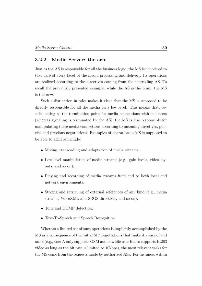
3.2.2 Media Server: the arm
Just as the AS is responsible for all the business logic, the MS is conceived to
take care of every facet of the media processing and delivery. Its operations
are realized according to the directives coming from the controlling AS. To
recall the previously presented example, while the AS is the brain, the MS
is the arm.
Such a distinction in roles makes it clear that the MS is supposed to be
directly responsible for all the media on a low level. This means that, be-
sides acting as the termination point for media connections with end users
(whereas signaling is terminated by the AS), the MS is also responsible for
manipulating these media connections according to incoming directives, poli-
cies and previous negotiations. Examples of operations a MS is supposed to
be able to achieve include:
• Mixing, transcoding and adaptation of media streams;
• Low-level manipulation of media streams (e.g., gain levels, video lay-
outs, and so on);
• Playing and recording of media streams from and to both local and
network environments;
• Storing and retrieving of external references of any kind (e.g., media
streams, VoiceXML and SRGS directives, and so on);
• Tone and DTMF detection;
• Text-To-Speech and Speech Recognition.
Whereas a limited set of such operations is implicitly accomplished by the
MS as a consequence of the initial SIP negotiations that make it aware of end
users (e.g., user A only supports GSM audio, while user B also supports H.263
video as long as the bit rate is limited to 10kbps), the most relevant tasks for
the MS come from the requests made by authorized ASs. For instance, within
An open-source implementation 31
the application logic of a conferencing scenario an AS may first attach an end
user to the MS in order to have them negotiate the available media between
each other, and subsequently instruct the MS into playing an announcement
(e.g., “Digit the PIN”) followed by a DTMF collection (to have the user
digit the conference pin number), and then into joining the user into the
conference mix itself.
All these requests, together with the related responses and event no-
tifications, flow through the already discussed control channel just as the
previously described SYNCH transaction does.
3.3 An open-source implementation
The standardization work on the MEDIACTRL architecture is almost com-
pleted. In order to help researchers and developers understand the architec-
ture and possibly dig out the flaws that may be hidden inside its specification,
we provided an open source implementation of the specified architecture, fol-
lowing the well known IETF motto “rough consensus, running code” Our
implementation has been developed on both the server and client sides, and
currently includes the core framework, the new MEDIACTRL protocol and
some of the control packages that can be employed in order to implement cus-
tom media manipulation. All the relevant details upon the implementation
choices will be presented in the following subsections.
It is worth noting that our prototype implementation also paved the way
for a call flow document [4] we are carrying on in the MEDIACTRL Working
Group. In fact, having a real world implementation of the protocol easily al-
lowed us to reproduce popular use case scenarios involving media by means
of the MEDIACTRL architecture, and consequently first-hand protocol in-
teractions between AS and MS.

An open-source implementation 32
IDLE / TERMINATE
CONTROL SENT
PENDING
UPDATE
200 / -
Error / Error
API CONTROL / send CONTROL
202 / -
REPORT PENDING / send 200
REPORT UPDATE / send 200
REPORT TERMINATE / send 200
REPORT TERMINATE / send 200
REPORT UPDATE / send 200
202 RECEIVED
Figure 3.2: The Application Server perspective in MEDIACTRL
3.3.1 Application Server: Asterisk
Starting from the client side, we had to take into account what was required
from a MEDIACTRL-enabled Application Server besides the business logic
itself. Considering that the specification clearly points out that such an
AS must support SIP, both for setting up the control channel with a MS by
means of the previously introduced COMEDIA negotiation and for attaching
User Agents to the MS through a 3PCC mechanism, once again the Asterisk
server introduced in Chapter 2 was perfectly suitable for us, as it provided
all the needed functionality.
The AS is in charge of appropriately controlling a Media Server in order
to provide advanced services to end-users. Fig. 3.2 gives a simplified view of
the protocol behavior of an AS interacting with a Media Server.
3.3.2 Media Server: Confiance VideoMixer
Coming to the MS itself, instead, the requirements were quite different than
the one we identified for the client side. In fact, as explained in the previous
section, a MEDIACTRL-enabled MS envisages low level media processing
and manipulation besides custom media delivery by means of RTP.
This obviously suggested us that such an implementation would have

An open-source implementation 33
Figure 3.3: Media Server SCFW State Diagram
strict real-time requirements, which led us into choosing C/C++ as the pro-
gramming language to use to implement it.
However, the preliminary step to any actual implementation of the frame-
work was indeed the investigation of the possible protocol states. This led
us into specifying a state diagram for the MS as depicted in Fig. 3.3, which
paved the ground for the implementation work itself.
While most of the code was written from scratch, we also decided to avoid
the not invented here syndrome and thus reuse as many existing open source
components as possible in the implementation.
The most important protocols to deal with were of course SIP and SDP.
We needed a powerful and flexible SIP stack, capable to provide us with
means to properly handle the 3PCC mechanism, as well as means to easily
extend the standard SIP protocol with respect to both headers and bodies,
in order to cope with the additional functionality envisaged in the MEDI-
ACTRL specification (e.g., the COMEDIA negotiation and the ctrl-package
SDP attribute). Thus, we chose the C++ reSIProcate1 library as our SIP
stack, which provided us with powerful means to deal with SIP behavior.
This library is indeed well known in the open source community, and has
1See http://www.resiprocate.org

An open-source implementation 34
many active IETF participants among its contributors. Besides, it has also
been successfully used in many commercial projects as well, including two
widespread SIP softphones, namely X-Lite and Eyebeam.
When coming to RTP, instead, we decided to make use of the open source
C library oRTP2.
Considering all the currently specified packages make a heavy use of XML
for the framework messages bodies, we also had a strong need for a reliable
XML parser. Our choice fell on the widespread Expat3 library, a very well
known lightweight open source C component. The actual parsing of the XML
contents, anyway, was left to an additional component called Boost::regex.
Nevertheless, the list of protocols and meta-languages to handle did not
end here. In fact some packages currently require the support for retrieval of
external references. It is the example, for instance, of the Basic IVR package,
which allows in its specification to externally refer resources to be used within
dialogs, as remote media streams to play out in announcements, stored XML
files containing the actual directives for the package, SRGS grammar bodies
and so on. In order to appropriately satisfy this requirement, we made use
of another well known open source component called libcurl4. This library
allows for an easy retrieval of external files of any kind by supporting a wide
range of protocols, including HTTP, FTP and many others.
Of course, all these libraries only allowed us to handle the protocols
needed by the MEDIACTRL framework. Nevertheless, the framework would
not be complete without an actual media support with respect to codecs, in
order to properly implement the needed transcoding functionality. This led
us to make use of additional open source components, the most important
being the very well known ffmpeg5 piece of software. This software in fact
provides an easy API, called libavcodec, to deal with decoding and encoding
of media streams, and proved very useful especially when implementing our
2See http://www.linphone.org3See http://expat.sourceforge.net4See http://curl.haxx.se5See http://ffmpeg.mplayerhq.hu

Use Case Scenarios 35
video support for the framework.
All the aforementioned libraries were then integrated in the code we im-
plemented from scratch ourselves, which will be briefly described in the fol-
lowing lines with respect to the requirements we met.
Particular attention was required by the way media connections are con-
ceived in the specifications. In fact, such media connections can be addressed
at different levels of granularity, according to whether the specific media label
is included or not in the connection identifier. Hence, we specified wrapper
classes and related callbacks in order to properly drive the flow of media
accordingly.
For what concerns the MS itself, it was conceived to be modular with
respect to both codecs (audio and video) and control packages, for which we
designed a dedicated API. This allowed us to separate the design of the core
framework itself from the realization of proof of concept control packages and
codecs used to test the MS functionality. Our current implementation offers
good support to both audio (we support G.711 and GSM codecs) and video
(H.263 and H.264 codecs). Regarding the control packages, we focused on two
of the previously introduced ones, specifically Basic IVR and Conferencing.
This allowed us to reproduce many real-world scenarios by having the AS
properly orchestrate requests to the MS.
3.4 Use Case Scenarios
The presented implementation efforts allowed for the testing of proper real-
world use case scenarios involving media processing and delivery. Many of
these scenarios have been included in the already mentioned call flow doc-
ument [4], where snapshots of the full protocol interaction between AS and
MS for each of them are provided.
Having implemented two orthogonal packages with respect to the pro-
vided functionality, we were able to design several heterogeneous scenarios,
ranging from simple echo tests to phone calls, conferences and voice-mail
applications. Each scenario could be reproduced by properly orchestrating
Use Case Scenarios 36
different requests and by correlating the resulting output, just like a state ma-
chine. As a reference scenario to describe in this chapter we chose the Echo
Test one, which basically consists of a UAC directly or indirectly “talking”
to itself. The choice is motivated by the fact that, despite being a really sim-
ple example, this scenario can be achieved in several different ways, and so
proves to be quite useful when it comes to describing its implementation mak-
ing use of different approaches. Other scenarios can be achieved taking quite
similar approaches, by integrating different transactions in different fashions
within the application logic.
The upcoming scenario description will focus on the specifically scenario-
related interaction between the AS and the MS and the results in the UAC
experience. This implies that the example assumes that a Control Channel
has already been correctly established and SYNCHed between the reference
AS and MS as described in the previous sections. Similarly, the 3PCC session
among the AS, the MS and the interested UAC is also assumed to have
already happened.
Once all the preliminary steps have taken place, the actual scenario can
be reproduced and analyzed. We will herein provide the description of two
different ways an Echo Test scenario can be achieved, namely:
1. A Direct Echo Test approach, where the UAC directly talks to itself;
2. A Recording-based Echo Test approach, where the UAC indirectly talks
to itself.
3.4.1 Direct Echo Test
In the Direct Echo Test approach, the UAC is directly connected to itself.
This means that each frame the MS receives from the UAC is sent back to
it in real-time.
In the framework this can be achieved by means of the conference control
package, which is in charge of the task of joining connections and conferences.
Use Case Scenarios 37
UAC MSAS
1. CONTROL
(Join UAC to itself)
2. 200 OK
Self join
UAC
Now UAC is echoed back everything
Figure 3.4: Self Connection: Framework Transaction
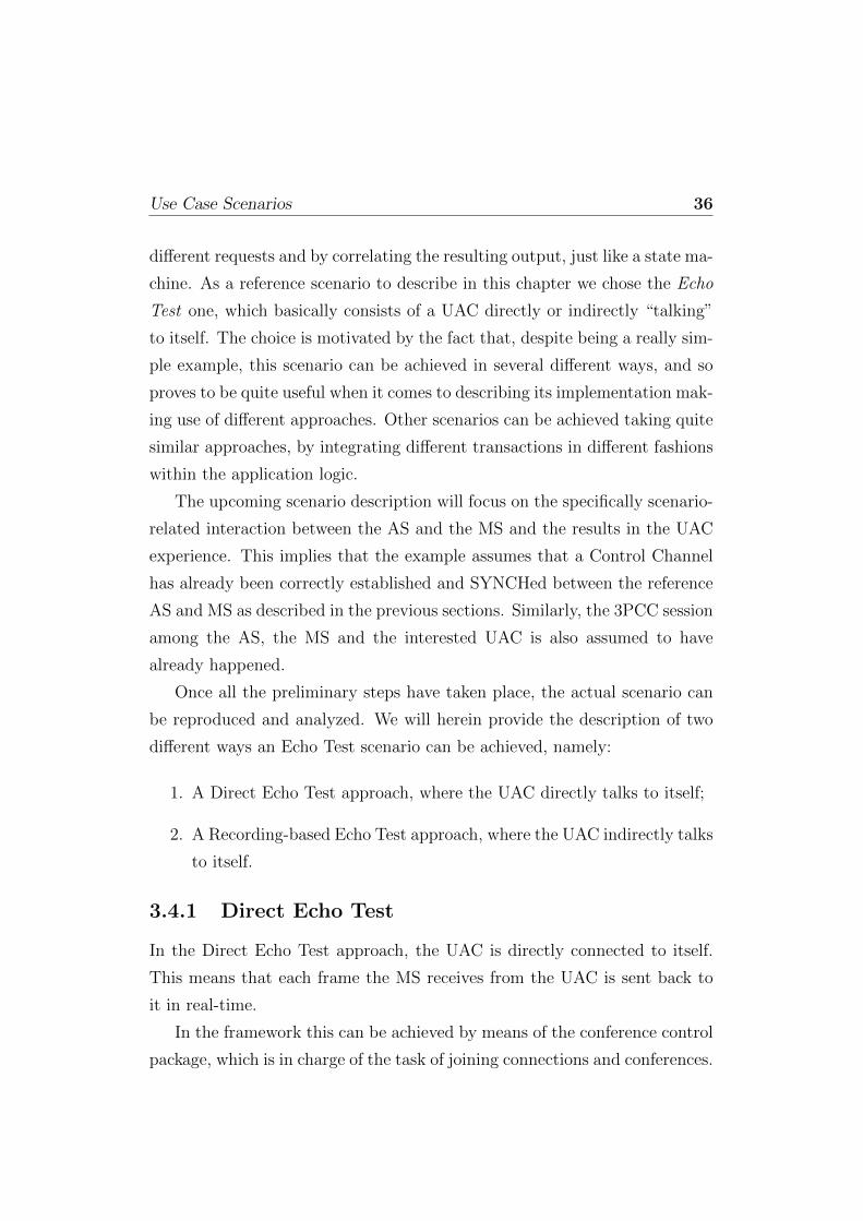
Specifically, the package method the AS has to make use of is called <join>,
and a sequence diagram of a potential transaction is depicted in Figure 3.4.
All the transaction steps have been numbered to ease the understanding
of the subsequent explanation lines:
• The AS requests the joining of the connection to itself by sending a
CONTROL request (1), specifically meant for the conferencing control
package (msc-conf-audio/1.0), to the MS: since the connection must
be attached to itself, the id1 and id2 attributes are set to the same
value, i.e., the connectionid;
• The MS, having checked the validity of the request, enforces the join of
the connection to itself; this means that all the frames sent by the UAC
are echoed back to it; to report the success of the operation, the MS
sends a 200 OK (2) in reply to the MS, thus ending the transaction.
The complete transaction, that is the full bodies of the exchanged mes-
sages, is provided in the following lines:
1. AS → MS (SCFW CONTROL)
SCFW 74b0dc511949 CONTROL
Control-Package: msc-conf-audio/1.0

Use Case Scenarios 38
Content-Type: text/xml
Content-Length: 87
<?xml version="1.0"?>
<join id1="1536067209~913cd14c" \
id2="1536067209~913cd14c">
</join>
2. AS ← MS (SCFW 200 OK)
SCFW 74b0dc511949 200
Content-Type: text/xml
Content-Length: 70
<?xml version="1.0"?>
<response status="200" reason="Join successful"/>
Such a transaction is the simplest form of transaction that can occurthrough the Control Channel. In fact, the reply to the CONTROL messageis immediately provided to the AS in a 200 message. This is not alwaystrue, since asynchronous events related to the original request may occurand consequently influence the AS state behavior.
3.4.2 Echo Test based on Recording
In the Recording-based Echo Test approach, the UAC is connected to itselfin an indirect fashion. This means that each frame the MS receives fromthe UAC is first recorded: then, when the recording process ends, the wholerecorded frames are played back to the UAC as an announcement. A wellknown application making use of this approach is Skype, which envisagesthree steps: (i) first, an announcement is played to the user agent (e.g., “Thisis an echo test, talk after the beep for 10 seconds”); (ii) then, a recording ofthe media sent by the user takes place; (iii) finally, the recording is playedback to the user, in order to make it aware of how his media would beperceived by a peer.
In MEDIACTRL, the presented three steps can be reproduced by meansof the basic IVR control package, which is in charge of the task of firstrecording and then playing out the recorded frames. Nevertheless, the wholescenario cannot be accomplished in a single transaction. At least two steps,in fact, have to be made:
1. First, a recording (preceded by an announcement, if requested) musttake place;
2. Then, a play-out of the previously recorded media must occur (whichagain can be preceded by an announcement, if the AS wishes so).

Use Case Scenarios 39
UAC MSAS
A1 CONTROL (Record)
A2. 202
Prepare &
start the
dialog
� “This is an echo test: tell something”
A3 REPORT (Pending)
A4 200 OK
A5 REPORT(Terminate)
A6 200 OK
“10 s of audio from UAC” � Save in
a file
B2 200 OK
B1 CONTROL(recordinfo) Use recorded file to play
announcement
C1 CONTROL (Prompt)
C2. 202
C3 REPORT (Pending)
Prepare &
start the
dialog
C4 200 OK
C5 REPORT(Terminate)
C6 200 OK
� “Playout of the 10 s recorded voice”
D2 200 OK
D1 CONTROL(recordinfo)
Figure 3.5: Recording-based Echo: Two Framework Transactions
This means that two separate transactions need to be invoked. A sequencediagram of a potential multiple transaction is depicted in Figure 3.5.
Notice how the AS-originated CONTROL transactions are terminatedas soon as the requested dialogs start: as specified in [18], the MS makesuse of a framework CONTROL message to report the result of the dialogand how it has proceeded. The two transactions (the AS-generated CON-TROL request and the MS-generated CONTROL event) are correlated bymeans of the associated dialog identifier, as it will become clearer from thefollowing lines. As before, all the transaction steps have been numbered toease up the understanding of the subsequent explanation lines. Besides, thetwo transactions are distinguished by the preceding letter (A,B=recording,C,D=playout).
• The AS, as a first transaction, invokes a recording on the UAC connec-tion by means of a CONTROL request (A1); the body is for the IVRpackage (msc-ivr-basic/1.0), and requests the start (dialogstart)of a new recording context (<record>); the recording must be pre-ceded by an announcement (<prompt>), must not last longer than 10s(maxtime), and cannot be interrupted by a DTMF tone (dtmfterm=false);

Use Case Scenarios 40
this has only to be done once (iterations), which means that if therecording does not succeed the first time, the transaction must fail; abeep has to be played (beep) right before the recording starts, to notifythe UAC;
• As seen before, the first responses to the request start flowing: theprovisional 202 (A2), the subsequent REPORT pending (A3), and itsrelated ACK (A4) from the AS;
• In the meanwhile, the MS prepares the dialog (e.g. by retrieving theannouncement file, for which a HTTP URL is provided, and by checkingthat the request is well formed) and if all is fine it starts it, whilenotifying the AS through a new REPORT (A5) with a terminatedstatus: the connection is then passed to the IVR package, which firstplays the announcement on the connection, followed by a beep, andthen records all the incoming frames to a buffer;
• The AS acknowledges the latest REPORT (A6), thus terminating thistransaction, and starts waiting for the result to come;
• Once the recording is over, the MS prepares a notification CONTROL(B1) whose body contains (<recordinfo>) the path to the recordedfile (in this case, a HTTP URL) which can be used by the AS in caseof need;
• The AS concludes this first recording transaction by acknowledging theCONTROL event (B2).
Now that the first transaction has ended, the AS has the 10s recordingof the UAC talking. It can let the UAC hear it by having the MS play it asan announcement:
• The AS, as a second transaction, invokes a play-out on the UAC connec-tion by means of a new CONTROL request (C1); the body is once againfor the IVR package (msc-ivr-basic/1.0), but this time it requeststhe start (dialogstart) of a new announcement context (<prompt>); thefile to be played is the one recorded before (media), and has only to beplayed once (iterations);
• Again, the usual provisional 202 (C2), the subsequent REPORT pend-ing (C3), and its ACK (C4) from the AS take place;
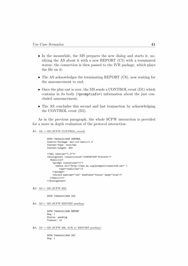
Use Case Scenarios 41
• In the meanwhile, the MS prepares the new dialog and starts it, no-tifying the AS about it with a new REPORT (C5) with a terminatedstatus: the connection is then passed to the IVR package, which playsthe file on it;
• The AS acknowledges the terminating REPORT (C6), now waiting forthe announcement to end;
• Once the play-out is over, the MS sends a CONTROL event (D1) whichcontains in its body (<promptinfo>) information about the just con-cluded announcement;
• The AS concludes this second and last transaction by acknowledgingthe CONTROL event (D2).
As in the previous paragraph, the whole SCFW interaction is providedfor a more in depth evaluation of the protocol interaction.
A1. AS → MS (SCFW CONTROL, record)
SCFW 74b0dc511949 CONTROL
Control-Package: msc-ivr-basic/1.0
Content-Type: text/xml
Content-Length: 354
<?xml version="1.0"?>
<dialogstart connectionid="1536067209~913cd14c">
<basicivr>
<prompt iterations="1">
<media src="http://www.ms.org/prompts/connected.wav" \
type="audio/wav"/>
</prompt>
<record maxtime="10s" dtmfterm="false" beep="true"/>
</basicivr>
</dialogstart>
A2. AS ← MS (SCFW 202)
SCFW 74b0dc511949 202
A3. AS ← MS (SCFW REPORT pending)
SCFW 74b0dc511949 REPORT
Seq: 1
Status: pending
Timeout: 10
A4. AS → MS (SCFW 200, ACK to ’REPORT pending’)
SCFW 74b0dc511949 200
Seq: 1

Use Case Scenarios 42
A5. AS ← MS (SCFW REPORT terminate)
SCFW 74b0dc511949 REPORT
Seq: 2
Status: terminate
Timeout: 10
Content-Type: text/xml
Content-Length: 88
<?xml version="1.0"?>
<response status="200" \
reason="Dialog started" dialogid="05ded7b"/>
A6. AS → MS (SCFW 200, ACK to ’REPORT terminate’)
SCFW 74b0dc511949 200
Seq: 2
B1. AS ← MS (SCFW CONTROL event)
SCFW 4rgth45632d1 CONTROL
Control-Package: msc-ivr-basic/1.0
Content-Type: text/xml
Content-Length: 197
<?xml version="1.0"?>
<event dialogid="05ded7b">
<dialogexit status="1">
<recordinfo termmode="maxtime" duration="10000" \
size="161644" type="audio/wav" \
recording="http://www.ms.org/recording-05ded7b.wav"/>
</dialogexit>
</event>
B2. AS → MS (SCFW 200, ACK to ’CONTROL event’)
SCFW 4rgth45632d1 200
C1. AS → MS (SCFW CONTROL, play)
SCFW 238e1f2946e8 CONTROL
Control-Package: msc-ivr-basic/1.0
Content-Type: text/xml
Content-Length: 319
<?xml version="1.0"?>
<dialogstart connectionid="1536067209~913cd14c">
<basicivr>
<prompt iterations="1">
<media src="http://www.ms.org/recording-05ded7b.wav" \
type="audio/wav"/>
</prompt>
</basicivr>
</dialogstart>
C2. AS ← MS (SCFW 202)
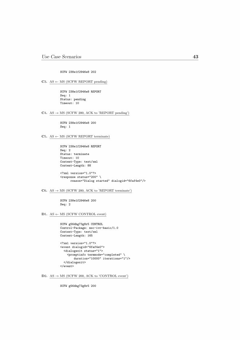
Use Case Scenarios 43
SCFW 238e1f2946e8 202
C3. AS ← MS (SCFW REPORT pending)
SCFW 238e1f2946e8 REPORT
Seq: 1
Status: pending
Timeout: 10
C4. AS → MS (SCFW 200, ACK to ’REPORT pending’)
SCFW 238e1f2946e8 200
Seq: 1
C5. AS ← MS (SCFW REPORT terminate)
SCFW 238e1f2946e8 REPORT
Seq: 2
Status: terminate
Timeout: 10
Content-Type: text/xml
Content-Length: 88
<?xml version="1.0"?>
<response status="200" \
reason="Dialog started" dialogid="6faf4e0"/>
C6. AS → MS (SCFW 200, ACK to ’REPORT terminate’)
SCFW 238e1f2946e8 200
Seq: 2
D1. AS ← MS (SCFW CONTROL event)
SCFW g56dhg73g8r5 CONTROL
Control-Package: msc-ivr-basic/1.0
Content-Type: text/xml
Content-Length: 165
<?xml version="1.0"?>
<event dialogid="6faf4e0">
<dialogexit status="1">
<promptinfo termmode="completed" \
duration="10000" iterations="1"/>
</dialogexit>
</event>
D2. AS → MS (SCFW 200, ACK to ’CONTROL event’)
SCFW g56dhg73g8r5 200

MEDIACTRL in Meetecho 44
3.5 MEDIACTRL in Meetecho
In Chapter 2 we described the current implementation of the Meetecho con-ferencing system and introduced two main server-side elements: the Asteriskserver and the Confiance VideoMixer component. The former plays the roleof the Focus, as envisaged by the XCON specifications, while the latter takescare of media streams manipulation and handling. We implemented the inter-action between these two components following the MEDIACTRL approachdescribed in this chapter. Such adherence to the separation of concerns prin-ciple represents a first step towards a scalable system: in fact, we separatedthe signaling and conference management tasks (and the server-side of theadditional functionality described in Section 2.4, too) from the handling ofRTP streams. This last task is indeed very CPU intensive, as it encompassesmedia transcoding and mixing on a per user basis.
It is worth mentioning that a further step in the direction of a scalablesystem might be accomplished by implementing the Media Resource Brokerrole the MEDIACTRL working group is still working on [8]. Such entitymanages the availability of Media Servers and the media resource demandsof Application Servers when a M:N topology is envisaged.
Chapter 4
DCON: a scalable distributedconferencing framework
4.1 Introduction
The distributed conferencing architecture we defined has been conceived to
be highly reliable and scalable. It has been called DCON [24], standing
for Distributed Conferencing, but at the same time explicitly recalling the
already mentioned XCON model.
DCON is based on the idea that a distributed conference can be setup by
appropriately orchestrating the operation of a set of XCON focus elements,
each in charge of managing a certain number of participants distributed
across a geographical network. Interaction between each participant and the
corresponding conference focus is based on the standard XCON framework,
whereas inter-focus interaction has been completely defined and specified by
us. In this chapter, we will describe a set of protocols we identified which
are complementary to the call signaling protocols and are needed for sup-
porting advanced conferencing applications, and we will provide the reader
with some information about how we implemented the proposed distributed
framework by extending the Meetecho platform described in Chapter 2.
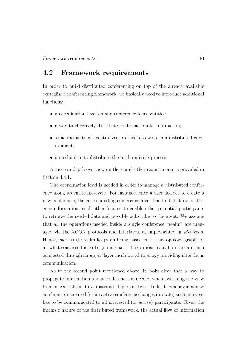
Framework requirements 46
4.2 Framework requirements
In order to build distributed conferencing on top of the already available
centralized conferencing framework, we basically need to introduce additional
functions:
• a coordination level among conference focus entities;
• a way to effectively distribute conference state information;
• some means to get centralized protocols to work in a distributed envi-
ronment;
• a mechanism to distribute the media mixing process.
A more in-depth overview on these and other requirements is provided in
Section 4.4.1.
The coordination level is needed in order to manage a distributed confer-
ence along its entire life-cycle. For instance, once a user decides to create a
new conference, the corresponding conference focus has to distribute confer-
ence information to all other foci, so to enable other potential participants
to retrieve the needed data and possibly subscribe to the event. We assume
that all the operations needed inside a single conference “realm” are man-
aged via the XCON protocols and interfaces, as implemented in Meetecho.
Hence, each single realm keeps on being based on a star-topology graph for
all what concerns the call signaling part. The various available stars are then
connected through an upper-layer mesh-based topology providing inter-focus
communication.
As to the second point mentioned above, it looks clear that a way to
propagate information about conferences is needed when switching the view
from a centralized to a distributed perspective. Indeed, whenever a new
conference is created (or an active conference changes its state) such an event
has to be communicated to all interested (or active) participants. Given the
intrinsic nature of the distributed framework, the actual flow of information
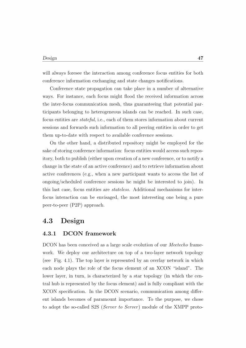
Design 47
will always foresee the interaction among conference focus entities for both
conference information exchanging and state changes notifications.
Conference state propagation can take place in a number of alternative
ways. For instance, each focus might flood the received information across
the inter-focus communication mesh, thus guaranteeing that potential par-
ticipants belonging to heterogeneous islands can be reached. In such case,
focus entities are stateful, i.e., each of them stores information about current
sessions and forwards such information to all peering entities in order to get
them up-to-date with respect to available conference sessions.
On the other hand, a distributed repository might be employed for the
sake of storing conference information: focus entities would access such repos-
itory, both to publish (either upon creation of a new conference, or to notify a
change in the state of an active conference) and to retrieve information about
active conferences (e.g., when a new participant wants to access the list of
ongoing/scheduled conference sessions he might be interested to join). In
this last case, focus entities are stateless. Additional mechanisms for inter-
focus interaction can be envisaged, the most interesting one being a pure
peer-to-peer (P2P) approach.
4.3 Design
4.3.1 DCON framework
DCON has been conceived as a large scale evolution of our Meetecho frame-
work. We deploy our architecture on top of a two-layer network topology
(see Fig. 4.1). The top layer is represented by an overlay network in which
each node plays the role of the focus element of an XCON “island”. The
lower layer, in turn, is characterized by a star topology (in which the cen-
tral hub is represented by the focus element) and is fully compliant with the
XCON specification. In the DCON scenario, communication among differ-
ent islands becomes of paramount importance. To the purpose, we chose
to adopt the so-called S2S (Server to Server) module of the XMPP proto-

Implementation 48
Figure 4.1: DCON design: the stateful approach
col. XMPP has been standardized by the IETF as the candidate protocol to
support instant messaging, e-presence and generic request-response services,
and it looked to us as the ideal communication means among DCON focus
entities.
In the following section we will present a prototype solution based on the
stateful approach.
4.4 Implementation
In this section we provide some useful information about the current imple-
mentation of the DCON framework. We will herein focus on a prototype
which implements the DCON basic functionality by assuming a stateful sce-
nario. Fig. 4.2 depicts the main implementation choices of the DCON archi-
tecture.
The right-hand side of the picture presents the logical view of the server,
integrating our Asterisk-based Meetecho implementation of the XCON focus
(upper box) with a brand new module specifically conceived for the SPreAd-
ing of Conference Events (which we called SPACE ). SPACE has been re-
alized as a plug-in for Openfire (lower box), a popular open source instant
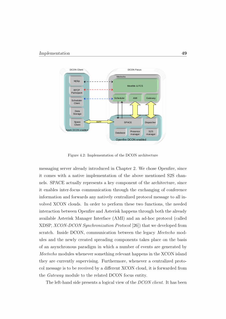
Implementation 49
Gateway
MeetMe & FCS
DispatcherSPACE
DatabaseS2S
manager
DCON Focus
Openfire DCON enabled
Confiance
AMIScheduler
Presencemanager
DCON Client
Spark DCON enabled
MjSip
BFCP Participant
SchedulerClient
Space Client
Data Storage
XMPP
Meetecho
Figure 4.2: Implementation of the DCON architecture
messaging server already introduced in Chapter 2. We chose Openfire, since
it comes with a native implementation of the above mentioned S2S chan-
nels. SPACE actually represents a key component of the architecture, since
it enables inter-focus communication through the exchanging of conference
information and forwards any natively centralized protocol message to all in-
volved XCON clouds. In order to perform these two functions, the needed
interaction between Openfire and Asterisk happens through both the already
available Asterisk Manager Interface (AMI) and an ad-hoc protocol (called
XDSP, XCON-DCON Synchronization Protocol [26]) that we developed from
scratch. Inside DCON, communication between the legacy Meetecho mod-
ules and the newly created spreading components takes place on the basis
of an asynchronous paradigm in which a number of events are generated by
Meetecho modules whenever something relevant happens in the XCON island
they are currently supervising. Furthermore, whenever a centralized proto-
col message is to be received by a different XCON cloud, it is forwarded from
the Gateway module to the related DCON focus entity.
The left-hand side presents a logical view of the DCON client. It has been

Implementation 50
designed as an integrated entity realized extending the Meetecho client de-
scribed in Chapter 2, and capable to interact with the framework by means of
SIP (MjSIP in the figure) as well as BFCP (Participant), CCMP (Scheduling
Client), and instant messaging (SpaceClient).
4.4.1 Inter-focus interaction
The SPACE module has been conceived to enable DCON functionality both
on the server and on the client side. The following paragraphs will explain
the respective roles in further detail.
Server side
On the server side, according to [25] we had to introduce support for the
following new features:
1. Core functionality of the DCON focus:
We concentrated our efforts on the integration between the Asterisk-
based Meetecho server and the newly introduced DCON Openfire com-
ponent. In order to offer a richer experience to users, we also im-
plemented a direct communication channel with the Meetecho XCON
scheduler for session management. Both the above mentioned features
rely on the existence of a conference database, which we also imple-
mented from scratch. The database contains relevant information re-
garding both active and registered DCON conferences;
2. Focus discovery:
We chose to implement such new feature based on a client-driven IM
presence service. Whenever the first client becomes active in a DCON
cloud, the related focus entity opens an S2S channel towards all other
focus entities it is aware of, thus triggering the spreading phase;
3. Information sharing:
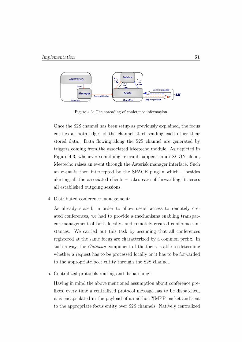
Implementation 51
MEETECHO
Manager SPACE
Database
S2S
Incoming session
Outgoing session
Event
Event notification
Asterisk Openfire
ActiveFocusentitiesLocaleventstoring Remoteeventstoring
Figure 4.3: The spreading of conference information
Once the S2S channel has been setup as previously explained, the focus
entities at both edges of the channel start sending each other their
stored data. Data flowing along the S2S channel are generated by
triggers coming from the associated Meetecho module. As depicted in
Figure 4.3, whenever something relevant happens in an XCON cloud,
Meetecho raises an event through the Asterisk manager interface. Such
an event is then intercepted by the SPACE plug-in which – besides
alerting all the associated clients – takes care of forwarding it across
all established outgoing sessions.
4. Distributed conference management:
As already stated, in order to allow users’ access to remotely cre-
ated conferences, we had to provide a mechanisms enabling transpar-
ent management of both locally- and remotely-created conference in-
stances. We carried out this task by assuming that all conferences
registered at the same focus are characterized by a common prefix. In
such a way, the Gateway component of the focus is able to determine
whether a request has to be processed locally or it has to be forwarded
to the appropriate peer entity through the S2S channel.
5. Centralized protocols routing and dispatching:
Having in mind the above mentioned assumption about conference pre-
fixes, every time a centralized protocol message has to be dispatched,
it is encapsulated in the payload of an ad-hoc XMPP packet and sent
to the appropriate focus entity over S2S channels. Natively centralized

Implementation 52
protocol messages include, but are not limited to, any protocol defined
and specified in the XCON framework. We will show in Appendix A
how we coped with the dispatching of the BFCP protocol.
6. Distributed mixing:
As soon as two or more centralized conferencing islands get connected
in order to provide for a distributed conferencing scenario, we also
cope with the issue of mixing media flows generated by the conference
participants. In order to optimize the performance of the overall ar-
chitecture, each focus is in charge of mixing the media streams of the
island it supervises, and subsequently sending it over an RTP trunk to
all the other foci involved in the scenario.
Client side
On the client side, we developed from scratch an integrated component that
offers the following functionality: (i) retrieval and visualization of confer-
ence information; (ii) creation of a new DCON conference; (iii) joining (and
unjoining) to an existing DCON conference; (iv) support to moderation.
In the following of this section we will briefly touch on all of the above
mentioned points.
Regarding the visualization of conference information, we already showed
how we provided the Spark client with a dedicated panel showing the details
about both active and scheduled conferences (see Fig. 2.4 in Chapter 2).
As described in the previous section, upon activation of the first con-
nection in an XCON cloud, the focus opens the S2S channels towards the
peering entities and immediately thereafter sends the retrieved conference
information to the connecting client. Moreover, if an active connection be-
tween the client and the focus is already in place, it is nonetheless possible
for the client to asynchronously contact its reference focus in order to have
up to date information about available conferences.
As to the joining of a conference hosted by a remote focus, we show in
Fig. 4.4 the relevant information flow. As already said, in this case the inter-
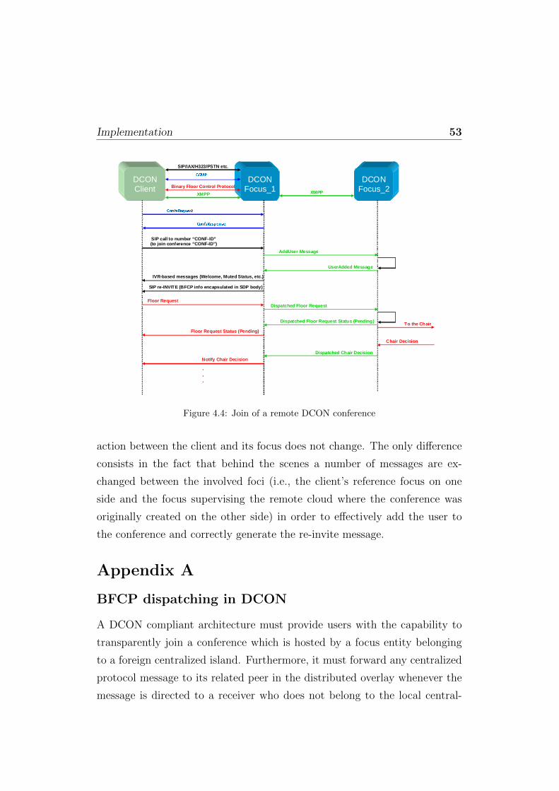
Implementation 53
DCONClient
DCONFocus_1
SIP/IAX/H323/PSTN etc.
Scheduling Protocol
Binary Floor Control Protocol
Query Conferences (Active/Registered)
Conferences: List of Conferences
SIP call to number “CONF-ID”(to join conference “CONF-ID”)
IVR-based messages (Welcome, Muted Status, etc.)
SIP re-INVITE (BFCP info encapsulated in SDP body)
Floor Request
Floor Request Status (Pending)
To the Chair
Chair Decision
Notify Chair Decision
.
.
.
XMPP
DCONFocus_2
AddUser Message
UserAdded Message
Dispatched Floor Request
Dispatched Floor Request Status (Pending)
Dispatched Chair Decision
XMPPConfsRequest ConfsResponseCCMP
Figure 4.4: Join of a remote DCON conference
action between the client and its focus does not change. The only difference
consists in the fact that behind the scenes a number of messages are ex-
changed between the involved foci (i.e., the client’s reference focus on one
side and the focus supervising the remote cloud where the conference was
originally created on the other side) in order to effectively add the user to
the conference and correctly generate the re-invite message.
Appendix A
BFCP dispatching in DCON
A DCON compliant architecture must provide users with the capability to
transparently join a conference which is hosted by a focus entity belonging
to a foreign centralized island. Furthermore, it must forward any centralized
protocol message to its related peer in the distributed overlay whenever the
message is directed to a receiver who does not belong to the local central-

Implementation 54
ized system. Our implementation of the DCON system fully complies with
the mentioned requirements. In fact, in order to join a remote conference the
participant only needs to interact with its corresponding focus in exactly the
same way as he did in the centralized case. Upon reception of the partici-
pant’s request, the local focus forwards join information to the focus entity
belonging to the island in which the conference in question was created. Due
to the large number of peer entities each focus could be in touch with, in a
distributed scenario a mechanism to prevent collisions in the assignment of
centralized protocols identifiers is needed. We achieved this goal by means
of the label swapping process explained with the following example.
To make the whole thing clearer, we deal with the case where a user
(Client (A)) belonging to XCON cloud (A) wants to remotely participate in
a distributed conference hosted by XCON cloud (B). Fig. 4.5 shows how this
kind of join requests is handled by the local focus in order to both dispatch
them and create a sort of virtual labels path needed to correctly manage
future messages addressed to the same user in the same conference.
1. Once the client has locally joined the distributed conference by placing
a SIP call to the focus it belongs to (XCON (A)), the focus chooses a
new label for Client (A) which will be used to appropriately dispatch
all messages related to it;
2. XCON (A) at this point forwards the join request to its related DCON
focus entity (DCON (A)); in this example this is done by sending,
through the XCON-DCON Synchronization Protocol (XDSP), a mes-
sage called AddUser, containing the newly assigned client’s label A;
3. DCON (A) receives the join request; since it regards a new client, the
DCON focus entity chooses a new label (e.g., XYZ) and associates it
with the just received label A; depending on the distributed confer-
ence the client wants to join, it associates the label (XYZ) with the
DCON focus entity managing the XCON focus physically hosting the
conference (DCON (B)) and forwards the join request to it;

Implementation 55
Client(A)
XCON (A)
DCON (A)
DCON (B)
XCON (B)
SIP INVITE
SIP OK
SIP ACKChoose a Label(A) for new user
AddUser (A)
SIP Trying
SIP OK
SIP ACK
Choose a Label(XYZ) and finddestination
SIP Trying
Label swap(A XYZ)
XMPP AddUser Choose a Label(B) for new user
Assignnew user
ID toremote participant
AddUser(B)
UserAdded (B)Label swap(B XYZ)
XMPP UserAddedLabel swap(XYZ A)
UserAdded(A)SIP REINVITE
(BFCP)
Figure 4.5: Joining a remote conference
4. DCON (B) receives the forwarded message through a server-to-server
(s2s) channel based on the XMPP protocol; since it regards a new client,
DCON (B) chooses a new label (e.g., B) and associates it with the just
received label XYZ; since the conference the remote Client (A) wants
to join is physically hosted by XCON (B), the join request is forwarded
there using the XDSP protocol, with an AddUser message containing
the newly assigned label B which identifies the remote client;
5. XCON (B) receives the request, and thus associates the received label
B with the remote Client (A); all the operations needed to add the
new user to the conference are performed, and the new information is
sent back to the client through the same path. All the involved labels
(B, XYZ, A) will be properly swapped to route all XCON protocols
messages between the two entities.
Once XCON (A) receives the confirmation that the user has been success-
fully added to the remote conference, together with the related information,
the Client (A) is updated through a SIP re-INVITE containing the BFCP
information needed to communicate with the Floor Control Server.

Implementation 56
Client(A)
XCON (A)(Gateway)
DCON (A)
DCON (B)
BFCP message Get Label (A)
assigned to client/FCS
BFCP encoded in Base64 (A)
Label swap(A XYZ)
XMPP BFCP in Base64
XCON (B)(Gateway)
XCON (B)(FCS)
Get destination from label (DCON B)
Label swap(XYZ B)
BFCP encoded in Base64 (B)
Check Label (B) assigned to FCS/client
BFCP message
BFCP message
Check Label (B) assigned to FCS/client
XMPP BFCP in Base64
BFCP encoded in Base64 (B)
Label swap(B XYZ)
Get destination from label (DCON A)
Label swap(XYZ A)
BFCP encoded in Base64 (A) Check Label
(A) assigned to FCS/client
BFCP message
Figure 4.6: BFCP dispatching
From this moment on and for the entire life cycle of its participation
in the remote conference the local focus takes care of the user acting as a
gateway for all what concerns natively centralized protocols.
In order to make the reader as aware as possible of the mechanisms in-
volved in the experimental campaign presented in the following sections,
Figure 4.6 illustrates how BFCP is dispatched across the distributed envi-
ronment.
Continuing from the previous example, since XCON (B) is physically
hosting the conference, floor control will be entirely managed by its Floor
Control Server. All BFCP messages sent by the clients to the Floor Control
Server are intercepted by the local focus (specifically by its Gateway com-
ponent), and then forwarded to the Floor Control Server of XCON (B). We
have already seen how labels are assigned and swapped: the same labels will
be used for dispatching.
The flow of a typical message exchange can be seen as follows:

Implementation 57
1. Client (A) sends a BFCP message to the Floor Control Server; the
message is intercepted by XCON (A)’s gateway; the label assigned to
client (A) is retrieved, and used to forward the BFCP message to the
Dispatcher in DCON (A); of course, since BFCP messages are binary,
a proper Base64 encoding is performed to encapsulate the message in
our text-based XDSP protocol data unit;
2. Once DCON (A) receives the encapsulated BFCP message, the labels
are once again swapped (in this case, A → XYZ) and the message is
routed to the right destination (DCON (B));
3. DCON (B) will receive the message and swap labels again (XYZ →B); at this point, the encapsulated message will be forwarded to the
underlying XCON (B) Gateway to be further processed there;
4. The Gateway in XCON (B) will receive the encapsulated (and Base64-
encoded) BFCP message; after decoding it, the Gateway will analyze
the label marked in the message (B, in this case), and will understand
it is a message sent by a remote user (Client (A)) to the local Floor
Control Server. It will forward the (now ‘natively’ binary) message
there, where it will be processed;
5. In case FCS (B) needs to send a message to Client (A), exactly the
same operations will be performed, and the same path will be followed
through the needed label swaps among the involved peers. FCS (A),
while not actually managing the floors related to the remote conference
in which Client (A) is participating, will however be notified upon each
floor status change, so to appropriately update the local media mixes
when needed (e.g., to mute Client (A), thus excluding her/him from
XCON (A)’s local mix if FCS (B) has decided so).

Chapter 5
From theory to practice: ascalability analysis
5.1 Preliminary considerations
The objective of this chapter is to demonstrate how the migration from the
Meetecho centralized platform described in Chapter 2 to the DCON dis-
tributed environment (see Chapter 4 can improve the scalability of the overall
system. The performance tests we carried out focused on two aspects:
• the number of users the system is able to manage;
• the CPU load and hardware resources consumption given a certain
amount of users in the system.
In both cases we exploited the SIPp1 tool, an open source performance testing
tool for the SIP protocol that generates traffic according to a fully customiz-
able XML scenario file. While it includes some basic template files for the
most common call scenarios, we nonetheless had to create our own in or-
der to manage the re-INVITE message sent back from our Meetecho server,
together with the subsequent replies that constitute the second three way
handshake characterizing the joining of a conference. Another useful fea-
ture of SIPp is the possibility to send media traffic (both audio and video)
1http://sipp.sourceforge.net

Preliminary considerations 59
through RTP/pcap replay, thus not limiting the tests only to call signaling
related matters. Using SIPp, we were hence capable to stress both the cen-
tralized and the distributed platform. Though, in order to involve all the
components of the architecture in our analysis (including the Media Server
and the Floor Control Server), we also had to implement a “stresser” for
the BFCP protocol. Such a tool is capable to send FloorRequest and Floor-
Release BFCP messages to the FCS, thus enabling or disabling the mixing
operation for each call instance. On the other hand, when no BFCP func-
tionality is involved in the performance tests, the media mixer would not
be involved in the scenario at all, as the media streams coming from the
conferencing clients would just be discarded.
In the following, we first provide a brief description of the BFCP stresser
we implemented; then, we show the experimental results obtained when test-
ing the Application Sever alone (i.e., with no BFCP involvement) as well as
when involving the Media Server and the Floor Control Server.
The experimental campaign we conducted is based on the realization of
a great number of tests for a single scenario. This is done in order to avoid
basing our analysis on a potentially biased set of data. For each scenario,
we present a single result which is representative of the average case for that
scenario.
5.1.1 The BFCP stresser
As already mentioned, we wanted to involve in our measurement campaign
both the media mixer and the Floor Control Server, so the need arose for a
tool capable to send BFCP messages on behalf of the participants of a con-
ference. We remind that in order to build a BFCP message, we need the
transport address of the FCS, together with the related identifiers. Such in-
formation is encapsulated in the SDP body of the re-INVITE message the
focus sends back when a user joins a conference. In spite of this, we decided
to statically provide our tool with these data by means of a configuration file,
since we did not want to force the BFCP stresser to be co-located with the
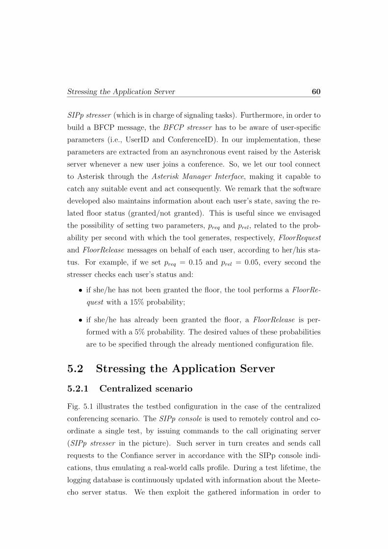
Stressing the Application Server 60
SIPp stresser (which is in charge of signaling tasks). Furthermore, in order to
build a BFCP message, the BFCP stresser has to be aware of user-specific
parameters (i.e., UserID and ConferenceID). In our implementation, these
parameters are extracted from an asynchronous event raised by the Asterisk
server whenever a new user joins a conference. So, we let our tool connect
to Asterisk through the Asterisk Manager Interface, making it capable to
catch any suitable event and act consequently. We remark that the software
developed also maintains information about each user’s state, saving the re-
lated floor status (granted/not granted). This is useful since we envisaged
the possibility of setting two parameters, preq and prel, related to the prob-
ability per second with which the tool generates, respectively, FloorRequest
and FloorRelease messages on behalf of each user, according to her/his sta-
tus. For example, if we set preq = 0.15 and prel = 0.05, every second the
stresser checks each user’s status and:
• if she/he has not been granted the floor, the tool performs a FloorRe-
quest with a 15% probability;
• if she/he has already been granted the floor, a FloorRelease is per-
formed with a 5% probability. The desired values of these probabilities
are to be specified through the already mentioned configuration file.
5.2 Stressing the Application Server
5.2.1 Centralized scenario
Fig. 5.1 illustrates the testbed configuration in the case of the centralized
conferencing scenario. The SIPp console is used to remotely control and co-
ordinate a single test, by issuing commands to the call originating server
(SIPp stresser in the picture). Such server in turn creates and sends call
requests to the Confiance server in accordance with the SIPp console indi-
cations, thus emulating a real-world calls profile. During a test lifetime, the
logging database is continuously updated with information about the Meete-
cho server status. We then exploit the gathered information in order to
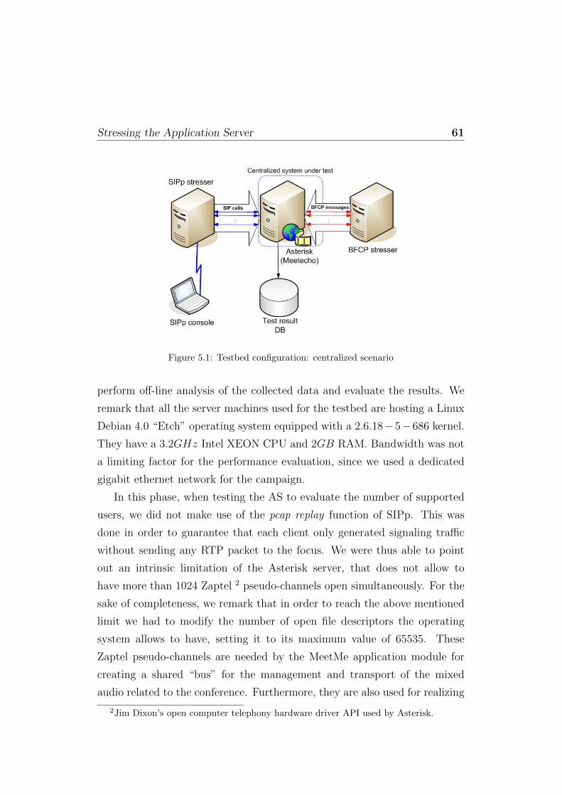
Stressing the Application Server 61
Figure 5.1: Testbed configuration: centralized scenario
perform off-line analysis of the collected data and evaluate the results. We
remark that all the server machines used for the testbed are hosting a Linux
Debian 4.0 “Etch” operating system equipped with a 2.6.18−5−686 kernel.
They have a 3.2GHz Intel XEON CPU and 2GB RAM. Bandwidth was not
a limiting factor for the performance evaluation, since we used a dedicated
gigabit ethernet network for the campaign.
In this phase, when testing the AS to evaluate the number of supported
users, we did not make use of the pcap replay function of SIPp. This was
done in order to guarantee that each client only generated signaling traffic
without sending any RTP packet to the focus. We were thus able to point
out an intrinsic limitation of the Asterisk server, that does not allow to
have more than 1024 Zaptel 2 pseudo-channels open simultaneously. For the
sake of completeness, we remark that in order to reach the above mentioned
limit we had to modify the number of open file descriptors the operating
system allows to have, setting it to its maximum value of 65535. These
Zaptel pseudo-channels are needed by the MeetMe application module for
creating a shared “bus” for the management and transport of the mixed
audio related to the conference. Furthermore, they are also used for realizing
2Jim Dixon’s open computer telephony hardware driver API used by Asterisk.
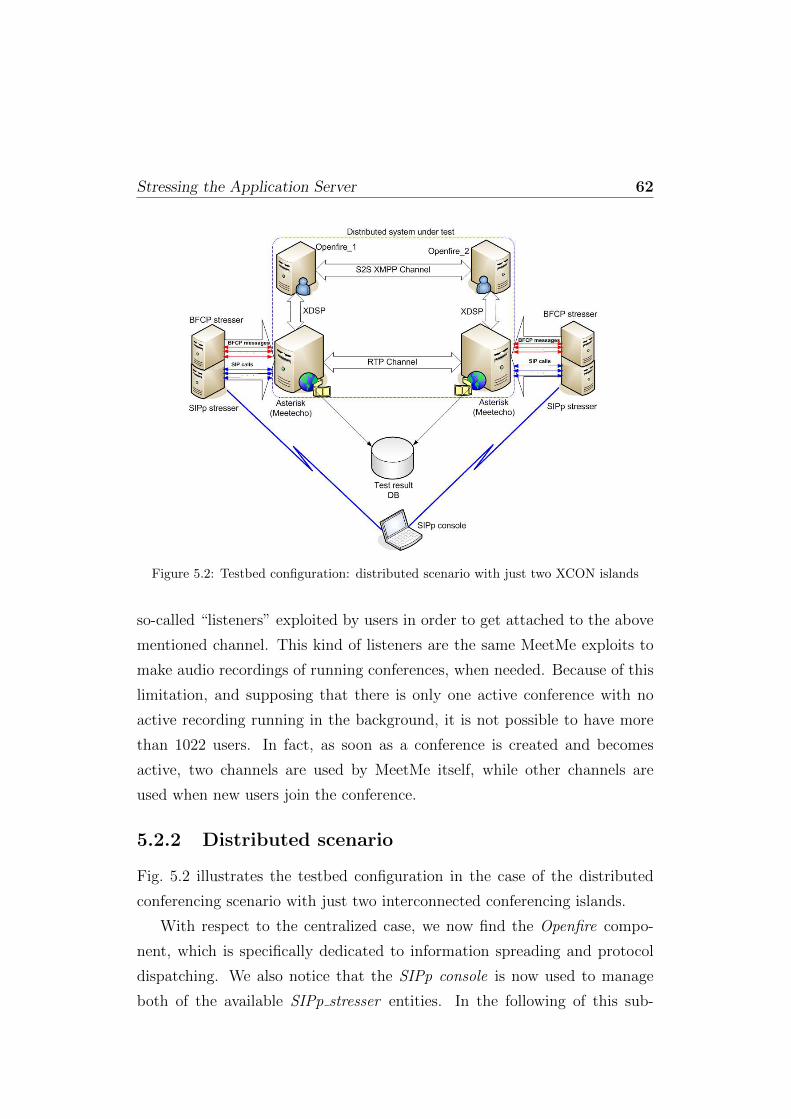
Stressing the Application Server 62
Figure 5.2: Testbed configuration: distributed scenario with just two XCON islands
so-called “listeners” exploited by users in order to get attached to the above
mentioned channel. This kind of listeners are the same MeetMe exploits to
make audio recordings of running conferences, when needed. Because of this
limitation, and supposing that there is only one active conference with no
active recording running in the background, it is not possible to have more
than 1022 users. In fact, as soon as a conference is created and becomes
active, two channels are used by MeetMe itself, while other channels are
used when new users join the conference.
5.2.2 Distributed scenario
Fig. 5.2 illustrates the testbed configuration in the case of the distributed
conferencing scenario with just two interconnected conferencing islands.
With respect to the centralized case, we now find the Openfire compo-
nent, which is specifically dedicated to information spreading and protocol
dispatching. We also notice that the SIPp console is now used to manage
both of the available SIPp stresser entities. In the following of this sub-
Involving the Media Server 63
section we will present results obtained in the distributed scenario, for an
increasing number of interconnected islands. Namely, we will analyze in de-
tail the results obtained, respectively, with two, three and four conferencing
clouds. We are not providing any illustration of the three- and four-elements
scenarios, which do not present any new feature when compared to the above
depicted two-elements case.
Coming to the tests, we have thoroughly explained in Chapter 4 how all
the users behind a remote focus are seen from the main focus. While their
signaling and control is managed through protocols dispatching and inter-
focus synchronization, their media (both audio and video) are locally mixed
on the remote focus, and then sent to the main focus as if they came from
a single user. The same thing obviously happens for the media flowing from
the main focus towards the remote foci as well. The main focus locally mixes
the media coming from its local users and from all the remote foci involved
in the conference, to which it forwards them. So, since only one RTP trunk
per medium is needed between each remote focus and the main focus, we
expected the maximum number of participants to linearly grow with the
number of “DCON islands”. This statement was promptly confirmed by our
tests in all cases (two-, three- and four-island topologies). It is important
to notice that each remote focus attached to the main focus means a new
listener on the shared bus channel, and so one less available channel for local
users. This last statement is true for both the main and the remote focus.
Fig. 5.3 summarizes the above considerations, by showing the linear increase
in the number of supported users in the four scenarios considered.
5.3 Involving the Media Server
5.3.1 Centralized scenario
When involving the media mixer in our scalability measurements, we fo-
cused on the resource consumption aspect of the scalability. We found that
the bottleneck is definitely represented by the CPU utilization level, rather

Involving the Media Server 64
Figure 5.3: Number of users supported in the four analyzed scenarios
than other relevant hardware parameters like, for example, available RAM
memory. In the following, we will hence focus just on CPU as the key perfor-
mance indicator. In this phase the BFCP stresser component of the testbed
comes into play, which hosts the tool we developed in order to generate BFCP
messages and consequently allow/deny the mixing of the media flows related
to each call. We made also use of the pcap replay functionality of SIPp, so
that each user sent both SIP and RTP traffic. Fig. 5.4 shows the CPU uti-
lization level in the presence of only one active conference and considering
all the participants to have been granted the audio floor. This behavior was
obtained by appropriately instructing the BFCP stresser to send a BFCP
FloorRequest on behalf of each user who joined the conference, and to never
release the obtained floor. It can be seen that when the number of partici-
pants approaches 180 the CPU load of the focus managing the conference is
close to 100%.
The result of 180 users as the peak value for the centralized scenario in
the presence of BFCP functionality will be used as a benchmarking param-
eter in the following subsection, which discusses the achievable performance
improvement in the distributed case.
It is worth noting that the results presented above, and in the following
as well, do not strictly depend on the assumption that all users participate

Involving the Media Server 65
0 20 40 60 80 100 120 140 160 1800
10
20
30
40
50
60
70
80
90
100
Calls
CP
U lo
ad [%
]
Figure 5.4: CPU utilization in the centralized scenario with moderation
0 20 40 60 80 100 120 140 160 1800
10
20
30
40
50
60
70
80
90
100
Calls
CP
U lo
ad [%
]
Figure 5.5: CPU utilization in the centralized scenario with moderation, in the presenceof 10 active conferences
in the same conference. To confirm this, we considered a more realistic
scenario characterized by 10 active conferences with 18 participants each.
This situation led to identical performance figures as shown in Fig. 5.5.
5.3.2 Distributed scenario
As already said, we wanted to study how the CPU performance improved
when moving from a centralized to a distributed environment. With this
objective in mind, we performed several testing experiments, assuming, as
in the centralized case, the presence of just one active conference with 180
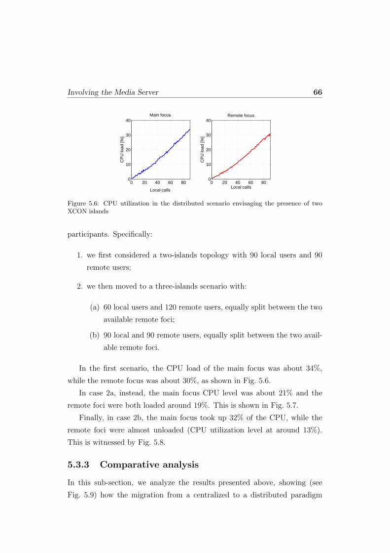
Involving the Media Server 66
0 20 40 60 800
10
20
30
40Main focus
Local calls
CP
U lo
ad [%
]
0 20 40 60 800
10
20
30
40Remote focus
Local calls
CP
U lo
ad [%
]Figure 5.6: CPU utilization in the distributed scenario envisaging the presence of twoXCON islands
participants. Specifically:
1. we first considered a two-islands topology with 90 local users and 90
remote users;
2. we then moved to a three-islands scenario with:
(a) 60 local users and 120 remote users, equally split between the two
available remote foci;
(b) 90 local and 90 remote users, equally split between the two avail-
able remote foci.
In the first scenario, the CPU load of the main focus was about 34%,
while the remote focus was about 30%, as shown in Fig. 5.6.
In case 2a, instead, the main focus CPU level was about 21% and the
remote foci were both loaded around 19%. This is shown in Fig. 5.7.
Finally, in case 2b, the main focus took up 32% of the CPU, while the
remote foci were almost unloaded (CPU utilization level at around 13%).
This is witnessed by Fig. 5.8.
5.3.3 Comparative analysis
In this sub-section, we analyze the results presented above, showing (see
Fig. 5.9) how the migration from a centralized to a distributed paradigm

Involving the Media Server 67
0 20 40 600
5
10
15
20
25Main focus
Local calls
CP
U lo
ad [%
]
0 20 40 600
5
10
15
20
25Remote focus 1
Local calls
CP
U lo
ad [%
]
0 20 40 600
5
10
15
20
25Remote focus 2
Local calls
CP
U lo
ad [%
]
Figure 5.7: CPU utilization in the distributed scenario envisaging the presence of threeXCON islands: case 2a
0 20 40 60 800
10
20
30
40Main focus
Local calls
CP
U lo
ad [%
]
0 20 400
10
20
30
40Remote focus 1
Local calls
CP
U lo
ad [%
]
0 20 400
10
20
30
40Remote focus 2
Local calls
CP
U lo
ad [%
]
Figure 5.8: CPU utilization in the distributed scenario envisaging the presence of threeXCON islands: case 2b
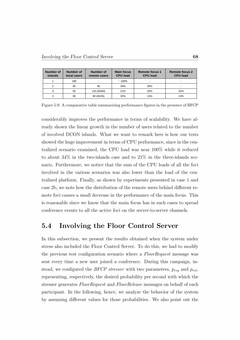
Involving the Floor Control Server 68
13%13%32%90 (45/45)903
20%20%21%120 (60/60)603
-30%34%90902
--˜ 100%-1801
Remote focus 2 CPU load
Remote focus 1 CPU load
Main focusCPU load
Number of remote users
Number of local users
Number of islands
Figure 5.9: A comparative table summarizing performance figures in the presence of BFCP
considerably improves the performance in terms of scalability. We have al-
ready shown the linear growth in the number of users related to the number
of involved DCON islands. What we want to remark here is how our tests
showed the huge improvement in terms of CPU performance, since in the cen-
tralized scenario examined, the CPU load was near 100% while it reduced
to about 34% in the two-islands case and to 21% in the three-islands sce-
nario. Furthermore, we notice that the sum of the CPU loads of all the foci
involved in the various scenarios was also lower than the load of the cen-
tralized platform. Finally, as shown by experiments presented in case 1 and
case 2b, we note how the distribution of the remote users behind different re-
mote foci causes a small decrease in the performance of the main focus. This
is reasonable since we know that the main focus has in such cases to spread
conference events to all the active foci on the server-to-server channels.
5.4 Involving the Floor Control Server
In this subsection, we present the results obtained when the system under
stress also included the Floor Control Server. To do this, we had to modify
the previous test configuration scenario where a FloorRequest message was
sent every time a new user joined a conference. During this campaign, in-
stead, we configured the BFCP stresser with two parameters, preq and prel,
representing, respectively, the desired probability per second with which the
stresser generates FloorRequest and FloorRelease messages on behalf of each
participant. In the following, hence, we analyze the behavior of the system
by assuming different values for those probabilities. We also point out the
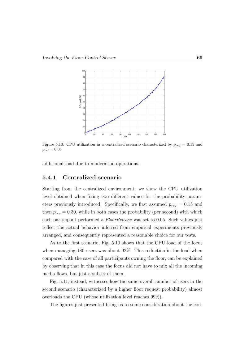
Involving the Floor Control Server 69
0 20 40 60 80 100 120 140 160 1800
10
20
30
40
50
60
70
80
90
100
Calls
CP
U lo
ad [%
]
Figure 5.10: CPU utilization in a centralized scenario characterized by preq = 0.15 andprel = 0.05
additional load due to moderation operations.
5.4.1 Centralized scenario
Starting from the centralized environment, we show the CPU utilization
level obtained when fixing two different values for the probability param-
eters previously introduced. Specifically, we first assumed preq = 0.15 and
then preq = 0.30, while in both cases the probability (per second) with which
each participant performed a FloorRelease was set to 0.05. Such values just
reflect the actual behavior inferred from empirical experiments previously
arranged, and consequently represented a reasonable choice for our tests.
As to the first scenario, Fig. 5.10 shows that the CPU load of the focus
when managing 180 users was about 92%. This reduction in the load when
compared with the case of all participants owning the floor, can be explained
by observing that in this case the focus did not have to mix all the incoming
media flows, but just a subset of them.
Fig. 5.11, instead, witnesses how the same overall number of users in the
second scenario (characterized by a higher floor request probability) almost
overloads the CPU (whose utilization level reaches 99%).
The figures just presented bring us to some consideration about the con-
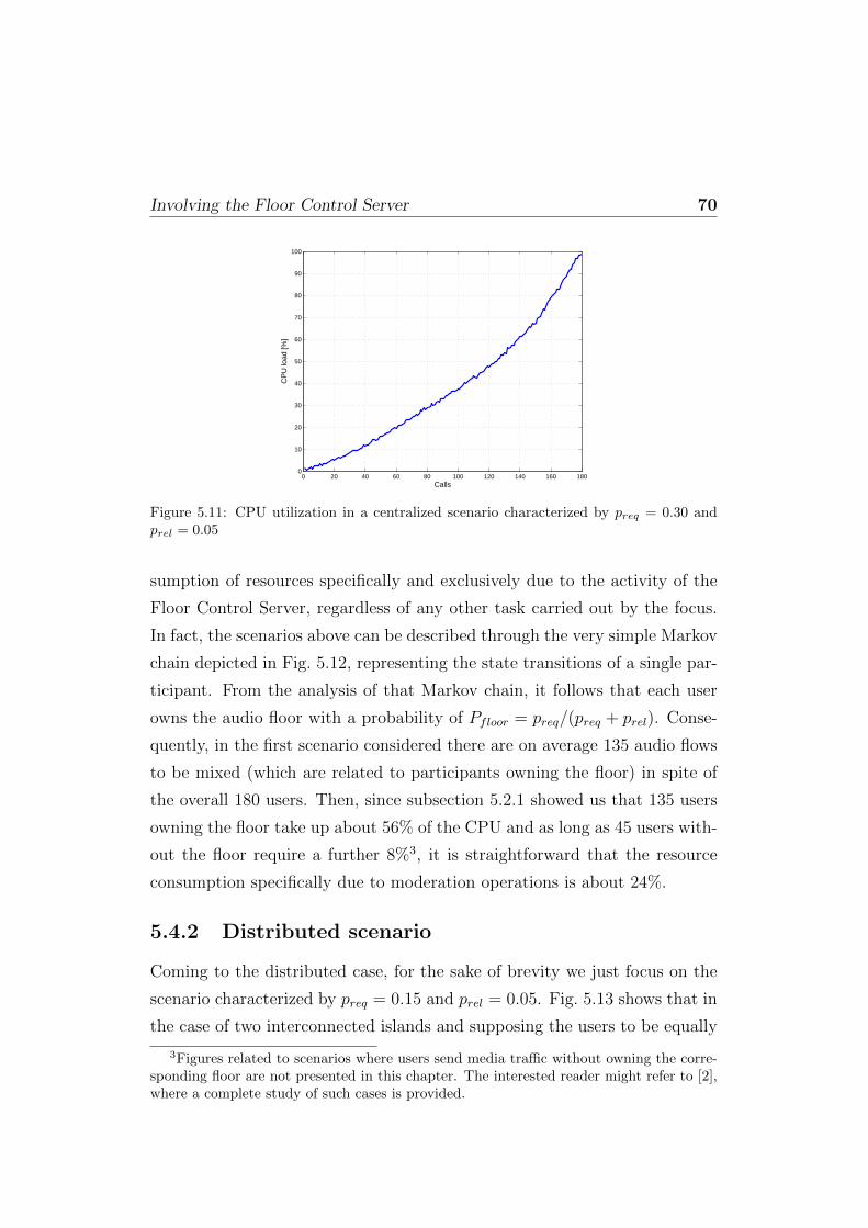
Involving the Floor Control Server 70
0 20 40 60 80 100 120 140 160 1800
10
20
30
40
50
60
70
80
90
100
Calls
CP
U lo
ad [%
]
Figure 5.11: CPU utilization in a centralized scenario characterized by preq = 0.30 andprel = 0.05
sumption of resources specifically and exclusively due to the activity of the
Floor Control Server, regardless of any other task carried out by the focus.
In fact, the scenarios above can be described through the very simple Markov
chain depicted in Fig. 5.12, representing the state transitions of a single par-
ticipant. From the analysis of that Markov chain, it follows that each user
owns the audio floor with a probability of Pfloor = preq/(preq + prel). Conse-
quently, in the first scenario considered there are on average 135 audio flows
to be mixed (which are related to participants owning the floor) in spite of
the overall 180 users. Then, since subsection 5.2.1 showed us that 135 users
owning the floor take up about 56% of the CPU and as long as 45 users with-
out the floor require a further 8%3, it is straightforward that the resource
consumption specifically due to moderation operations is about 24%.
5.4.2 Distributed scenario
Coming to the distributed case, for the sake of brevity we just focus on the
scenario characterized by preq = 0.15 and prel = 0.05. Fig. 5.13 shows that in
the case of two interconnected islands and supposing the users to be equally
3Figures related to scenarios where users send media traffic without owning the corre-sponding floor are not presented in this chapter. The interested reader might refer to [2],where a complete study of such cases is provided.

Involving the Floor Control Server 71
FLOORNOFLOOR
preq
prel
1-preq
1-prel
Figure 5.12: A Markov chain which describes moderated conferencing scenarios
0 20 40 60 800
10
20
30
40Main focus
Local calls
CP
U lo
ad [%
]
0 20 40 60 800
10
20
30
40Remote focus
Local calls
CP
U lo
ad [%
]
Figure 5.13: CPU utilization in a two-islands scenario characterized by preq = 0.15 andprel = 0.05
split between them, the CPU level of the main focus was about 33% while
the remote focus was loaded at around 32%.
Keeping on considering the participants equally split among the available
domains, the three-islands case was characterized, instead, by 21% CPU
consumption at the main focus and 20% at both remote foci (see Fig. 5.14).
In this subsection we do not deal with a comparative analysis between the
centralized and the distributed environment, since the same considerations
as in subsection 5.3.3 totally apply here.
Rather, we want to highlight how in the considered configuration of tests,
working with average values becomes really crucial. In fact, when a scenario
is characterized by a number of participants owning the floor that varies in
time, the CPU occupancy given a certain amount of users varies too. This
statement is confirmed by Fig. 5.15, showing the variation in time of the
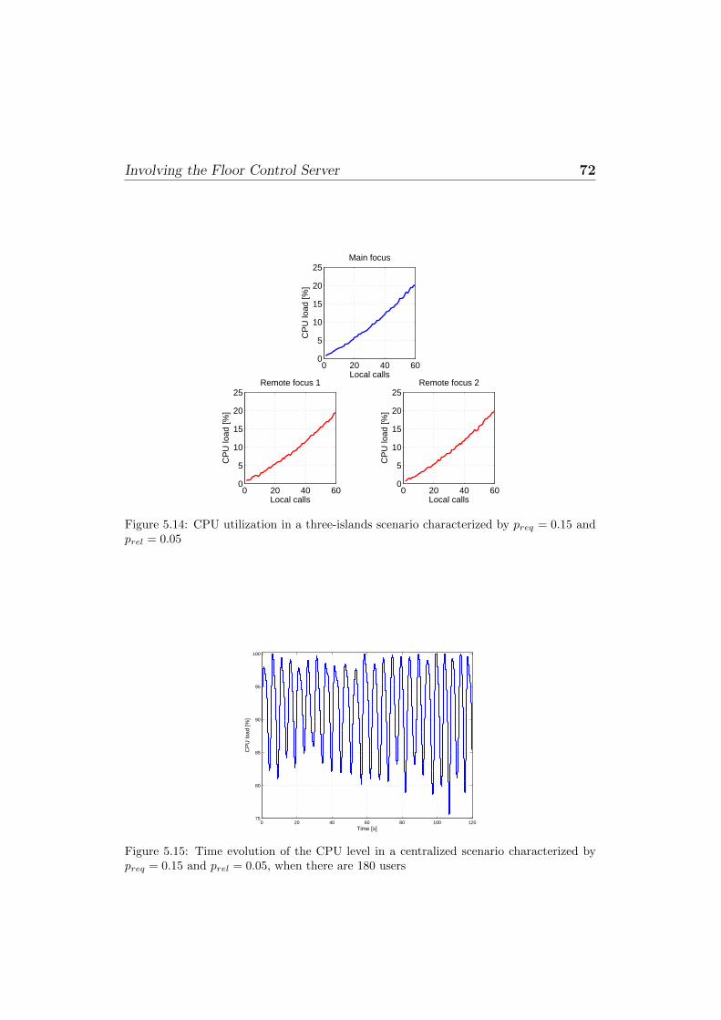
Involving the Floor Control Server 72
0 20 40 600
5
10
15
20
25Main focus
Local calls
CP
U lo
ad [%
]
0 20 40 600
5
10
15
20
25Remote focus 1
Local calls
CP
U lo
ad [%
]
0 20 40 600
5
10
15
20
25Remote focus 2
Local calls
CP
U lo
ad [%
]
Figure 5.14: CPU utilization in a three-islands scenario characterized by preq = 0.15 andprel = 0.05
0 20 40 60 80 100 12075
80
85
90
95
100
Time [s]
CP
U lo
ad [%
]
Figure 5.15: Time evolution of the CPU level in a centralized scenario characterized bypreq = 0.15 and prel = 0.05, when there are 180 users

Considerations 73
CPU level given a fixed number of participants, in a single-island case with
preq = 0.15 and prel = 0.05. Such a variable CPU level depends on the actual
number of audio flows that have to be mixed, since the less are the users able
to talk, the less is the load of the focus and vice versa.
5.5 Considerations
The work carried out and presented in this chapter was mainly focused on
a scalability assessment of the DCON framework in the presence of audio
mixing operations and floor control. The results obtained and discussed in
the previous sections show that our efforts in defining and implementing a
distributed framework, with the corresponding issues about both distributed
mixing and distribution of the floor control protocol, were well directed. Fur-
thermore, the stressing operations conducted during this test campaign also
proved very useful in finding any bug that may be hidden in the code and con-
sequently affect the expected behavior of the platform. Finally, with respect
to floor control, the performance figures we derived confirm the intuitive ex-
pectation that nothing comes for free. Moderation has to be paid for, since
it does represent an expensive task, especially on the server side, where state
information has to be kept and updated with reference to each and every
user who is participating in a conference.
Chapter 6
Troubleshooting
6.1 Introduction
This chapter is devoted to troubleshooting issues we had to face when we
decided to deploy our multimedia conferencing system in the actual Inter-
net, thus bringing the results of our research activities from the lab to the
real world. In fact, in order to let a complex and effective deployment of
multimedia conferencing scenarios work properly, there is the need for a “co-
operative” network, given the strong requirements they impose in terms of
full access to the underlying network topology and resources. Unfortunately,
this is often not the case for several different reasons. In the following, we will
describe the issues we encountered and how we managed to identify and solve
them by means of a network diagnosis architecture and a protocol tunneling
solution, respectively.
6.2 Issues
6.2.1 Signaling plane
We explained how our architecture leverages the SIP protocol in the signal-
ing plane. Such protocol, though it is the de-facto standard for instantiating
multimedia sessions over the Internet, is very sensitive to the presence of mid-
dleboxes along the signaling path, like Network Address Translators (NATs).

Issues 75
In fact, when the SIP protocol has been specified by the IETF community,
in the first place they neglected the issues NAT elements might cause, be-
ing confident that a full switch from IPv4 to IPv6 was forthcoming. They
stated that a User Agent (UA) must send the media to the transport ad-
dresses indicated in the SDP body, even if they are received from another
IP address and/or port. In scenarios where “natted” parties are involved,
this would clearly cause RTP packets to be sent to a private, non-routable,
IP address and to not be received form the other party. As the deployment
of NAT boxes became larger, a lot of efforts have been done in order to ad-
dress such issue. Within the IETF, the BEHAVE (Behavior Engineering for
Hindrance Avoidance) Working Group deals with the behavior of NATs and
has completed the definition of the STUN (Session Traversal Utilities for
NAT) [14] protocol, and is still working the TURN (Traversal Using Relay
NAT) [15] and ICE (Interactive Connectivity Establishment) [28] protocols,
too. Such NAT-traversal techniques try to make a UA send the media flows
to the correct transport address so that the remote party is able to receive
them. They operates in different ways: STUN learns a node’s reflexive trans-
port address1 and put it into the SDP body of SIP messages and into SIP
headers, too; TURN makes use of a relay agent to/from which a natted node
sends/receives the RTP streams; ICE combines the use of both STUN and
TURN in order to cross each possible type of NAT. Unfortunately, even if
there are lots of cases where the listed solutions work flawlessly, in some sce-
narios where very restrictive NATs are in place they are not able to do the
job. In these cases a different solution has to be exploited, and server-side
techniques are often the best choice. Meetecho, for the purpose, makes use
of the Asterisk SIP NAT solution, which consists in ignoring the address in-
formation in the SIP and SDP headers from this peer, and replying to the
sender’s IP address and port. Furthermore, Asterisk ignores the IP and port
in the SDP received from the peer and will wait for incoming RTP: after
that, it already knows where to send its RTP.
1From RFC 5389: the reflexive transport address is the public IP address and portcreated by the NAT closest to the server (i.e., the most external NAT)

Issues 76
6.2.2 Media plane
The issues presented in the previous subsection, while related to the signaling
plane, have strong repercussions on the media plane, as they result in the
impossibility to establish a bi-directional communication channel between a
caller and a callee. Moreover, problems in the media plane can also be due to
devices included in the media path, be them RTP proxies, Application Level
Gateways (ALGs) or NATs. Hence, problems in the media plane are hard
to be diagnosed, as a number of different yet often interdependent causes
might be the source. Section 6.3 will deal with fault diagnosis in networks
based on the SIP protocol, also presenting a very common RTP fault as a
representative scenario.
6.2.3 Proxy/Firewall traversal
It is not unusual that enterprises, work places, public entities like schools
and universities, as well as other secured environments, aim at limiting or
filtering out the traffic flowing across their networks. These limitations are
usually enforced by deploying more or less restrictive elements like firewalls
or proxies at the borders of the network topology, which limit the allowed
traffic according to a specific set of policy rules. Such rules may include
port- and/or domain-based filtering, filters on TCP or UDP traffic, payload
inspection, limitations on the type and number of supported protocols, etc.
It is not unlike to meet restrictive elements that only allow HTTP and/or
HTTPS traffic to pass through, with the HTTP traffic itself that might also
be subject to further, payload-based inspections. These scenarios are not new
at all, and solutions to effectively deal with them have already been proposed
and exploited with alternating success during the years. Specifically, the most
common approach that is exploited to get around such limitations is HTTP
tunneling. Such approach raises issues when exploited to carry protocols
that are sensitive to transport-related information, like the ones involved in
multimedia conferencing scenarios. In fact, as we will show in Section 6.4,
we had to implement a custom Meetecho-aware tunneling solution in order
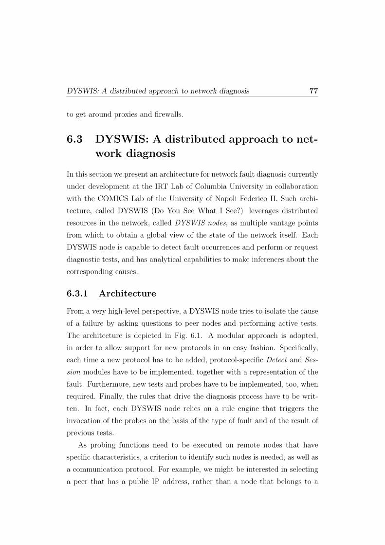
DYSWIS: A distributed approach to network diagnosis 77
to get around proxies and firewalls.
6.3 DYSWIS: A distributed approach to net-
work diagnosis
In this section we present an architecture for network fault diagnosis currently
under development at the IRT Lab of Columbia University in collaboration
with the COMICS Lab of the University of Napoli Federico II. Such archi-
tecture, called DYSWIS (Do You See What I See?) leverages distributed
resources in the network, called DYSWIS nodes, as multiple vantage points
from which to obtain a global view of the state of the network itself. Each
DYSWIS node is capable to detect fault occurrences and perform or request
diagnostic tests, and has analytical capabilities to make inferences about the
corresponding causes.
6.3.1 Architecture
From a very high-level perspective, a DYSWIS node tries to isolate the cause
of a failure by asking questions to peer nodes and performing active tests.
The architecture is depicted in Fig. 6.1. A modular approach is adopted,
in order to allow support for new protocols in an easy fashion. Specifically,
each time a new protocol has to be added, protocol-specific Detect and Ses-
sion modules have to be implemented, together with a representation of the
fault. Furthermore, new tests and probes have to be implemented, too, when
required. Finally, the rules that drive the diagnosis process have to be writ-
ten. In fact, each DYSWIS node relies on a rule engine that triggers the
invocation of the probes on the basis of the type of fault and of the result of
previous tests.
As probing functions need to be executed on remote nodes that have
specific characteristics, a criterion to identify such nodes is needed, as well as
a communication protocol. For example, we might be interested in selecting
a peer that has a public IP address, rather than a node that belongs to a
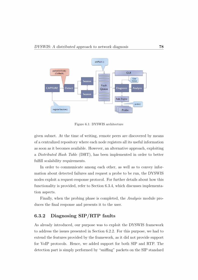
DYSWIS: A distributed approach to network diagnosis 78
Figure 6.1: DYSWIS architecture
given subnet. At the time of writing, remote peers are discovered by means
of a centralized repository where each node registers all its useful information
as soon as it becomes available. However, an alternative approach, exploiting
a Distributed Hash Table (DHT), has been implemented in order to better
fulfill scalability requirements.
In order to communicate among each other, as well as to convey infor-
mation about detected failures and request a probe to be run, the DYSWIS
nodes exploit a request-response protocol. For further details about how this
functionality is provided, refer to Section 6.3.4, which discusses implementa-
tion aspects.
Finally, when the probing phase is completed, the Analysis module pro-
duces the final response and presents it to the user.
6.3.2 Diagnosing SIP/RTP faults
As already introduced, our purpose was to exploit the DYSWIS framework
to address the issues presented in Section 6.2.2. For this purpose, we had to
extend the features provided by the framework, as it did not provide support
for VoIP protocols. Hence, we added support for both SIP and RTP. The
detection part is simply performed by “sniffing” packets on the SIP standard
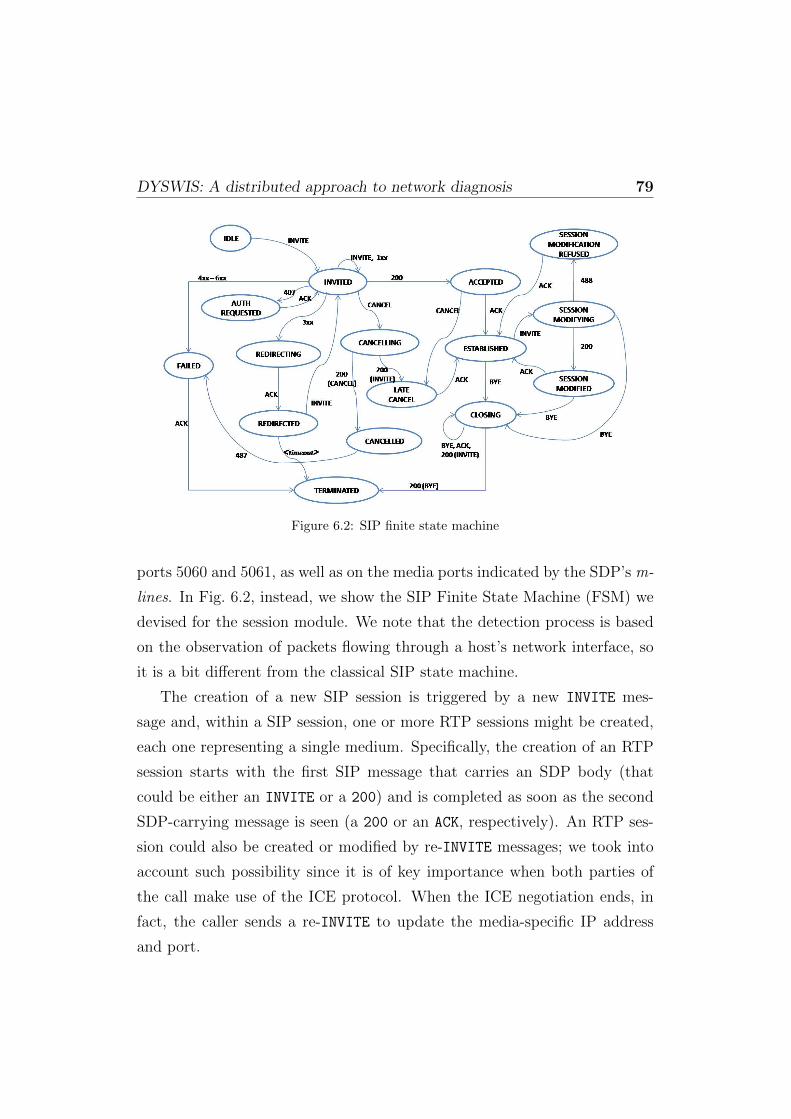
DYSWIS: A distributed approach to network diagnosis 79
Figure 6.2: SIP finite state machine
ports 5060 and 5061, as well as on the media ports indicated by the SDP’s m-
lines. In Fig. 6.2, instead, we show the SIP Finite State Machine (FSM) we
devised for the session module. We note that the detection process is based
on the observation of packets flowing through a host’s network interface, so
it is a bit different from the classical SIP state machine.
The creation of a new SIP session is triggered by a new INVITE mes-
sage and, within a SIP session, one or more RTP sessions might be created,
each one representing a single medium. Specifically, the creation of an RTP
session starts with the first SIP message that carries an SDP body (that
could be either an INVITE or a 200) and is completed as soon as the second
SDP-carrying message is seen (a 200 or an ACK, respectively). An RTP ses-
sion could also be created or modified by re-INVITE messages; we took into
account such possibility since it is of key importance when both parties of
the call make use of the ICE protocol. When the ICE negotiation ends, in
fact, the caller sends a re-INVITE to update the media-specific IP address
and port.
DYSWIS: A distributed approach to network diagnosis 80
6.3.3 Case study: one-way media issue
As a case study, we show how we address the well-known issue of one-way
RTP flows in VoIP communications by leveraging the DYSWIS diagnosing
capabilities. We investigate the main causes that usually lead to this type of
fault, and we detail the proposed methodology allowing for their automated
online detection and diagnosis. As most of the problems associated with
one-way RTP can be ascribed to the presence of NAT elements along the
communication path, one of the key features of the proposed methodology
resides in the capability to detect such type of devices. Besides, another
important aspect of this work is that the diagnosis is non-intrusive, meaning
that the whole process is based on the passive observation of flowing packets,
and on silent active probing that is transparent to the users. In this way,
we also avoid the possibility of being classified as SPIT (SPam over Internet
Telephony). We provide a thorough description of the various steps the
diagnosing process goes through, together with some implementation details
as well as the results of the validation process.
Causes
The problem of one-way RTP flows is very common in VoIP communications.
In this paragraph, we provide a classification of the causes that lead to such
kind of fault, by splitting them into four main categories.
Configuration problems Into this category fall all the problems that
can be ascribed to some error in the configuration of the machine hosting
a User Agent (UA). First of all, there are possible oversights in the config-
uration of the UA itself (e.g., wrong audio capture device selected). Then,
we have network interface configuration errors, that are quite common espe-
cially in multi-homed systems. In fact, it can happen to see RTP packets
being received and sent on two different network interfaces, for example on
machines having both a wired and wireless connection up (this is not unlikely
on Unix-based systems, and is usually due to the configuration stored in the

DYSWIS: A distributed approach to network diagnosis 81
/etc/hosts file). The presence of software firewalls not properly configured
can also cause one-way media flows: for example, if we want both audio and
video to be involved in the call, it would not be sufficient to open a couple
of ports, since each call leg consumes two ports (one for RTP and the other
for RTCP). Finally, we also classify IP address conflicts in the network as a
local configuration problem.
As we will see in Section 6.3.3, it is easy to diagnose problems falling into
this category.
NAT-related problems Most of the factors that can cause one-way
media flows fall into this category and are related to the presence of NAT el-
ements along the communication path. Several NAT traversal solutions have
been proposed by the Internet Engineering Task Force (IETF), namely the
STUN (Session Traversal Utilities for NAT) [14], TURN (Traversal Using
Relay NAT) [15] and ICE (Interactive Connectivity Establishment) [28] pro-
tocols and the Application Level Gateway (ALG) and RTP proxy elements.
If no such solution is employed, the User Agent is unable to receive RTP
packets. Even worse, even if a NAT traversal technique is employed, it can
happen that the “natted” party is anyhow unable to see incoming packets.
This is the case of the most widespread NAT traversal solution: the STUN
protocol. STUN is actually helpful in a number of cases; though, it is useless
when a User Agent is behind a symmetric NAT 2, in which case it experiences
one-way media flows. Furthermore, one more scenario where the STUN us-
age does not avoid one-way RTP flows is when both the caller and the callee
happen to be in the same subnet, since a lot of NAT elements discard pack-
ets received from the private network and destined to their own public IP
address. The last situation can happen also if the STUN protocol is not em-
ployed, but the NAT box has built-in SIP Application Level Gateway (ALG)
functionality. This is becoming very common, as many of today’s commercial
routers implement such feature. Unfortunately, poorly implemented ALGs
2For a thorough description of the different types of NAT, the reader can refer to [14].
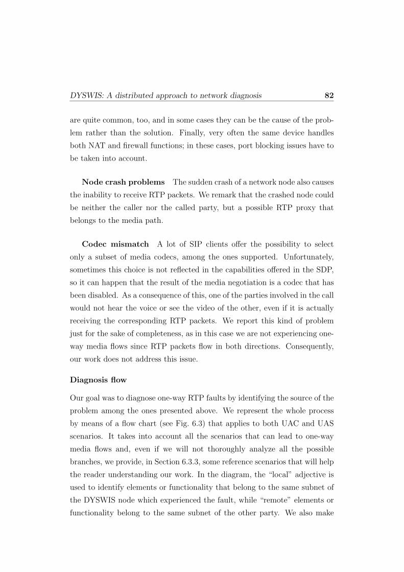
DYSWIS: A distributed approach to network diagnosis 82
are quite common, too, and in some cases they can be the cause of the prob-
lem rather than the solution. Finally, very often the same device handles
both NAT and firewall functions; in these cases, port blocking issues have to
be taken into account.
Node crash problems The sudden crash of a network node also causes
the inability to receive RTP packets. We remark that the crashed node could
be neither the caller nor the called party, but a possible RTP proxy that
belongs to the media path.
Codec mismatch A lot of SIP clients offer the possibility to select
only a subset of media codecs, among the ones supported. Unfortunately,
sometimes this choice is not reflected in the capabilities offered in the SDP,
so it can happen that the result of the media negotiation is a codec that has
been disabled. As a consequence of this, one of the parties involved in the call
would not hear the voice or see the video of the other, even if it is actually
receiving the corresponding RTP packets. We report this kind of problem
just for the sake of completeness, as in this case we are not experiencing one-
way media flows since RTP packets flow in both directions. Consequently,
our work does not address this issue.
Diagnosis flow
Our goal was to diagnose one-way RTP faults by identifying the source of the
problem among the ones presented above. We represent the whole process
by means of a flow chart (see Fig. 6.3) that applies to both UAC and UAS
scenarios. It takes into account all the scenarios that can lead to one-way
media flows and, even if we will not thoroughly analyze all the possible
branches, we provide, in Section 6.3.3, some reference scenarios that will help
the reader understanding our work. In the diagram, the “local” adjective is
used to identify elements or functionality that belong to the same subnet of
the DYSWIS node which experienced the fault, while “remote” elements or
functionality belong to the same subnet of the other party. We also make

DYSWIS: A distributed approach to network diagnosis 83
a distinction between tests and probes : the former class only exploits local
information, while the latter plays an active role by introducing packets into
the network. Finally, we explicitly mark the probes that need the help of a
cooperating node in order to be performed.
We observe that it is not always possible to exactly identify the cause of
the problem. The capability of making an accurate diagnosis, in fact, strictly
depends on the complexity of the network topology under consideration and
on actual availability of “remote” DYSWIS nodes, too. The ability to identify
such nodes is of key importance and is far from trivial. In fact, when a remote
node belongs to a private network environment (i.e., the remote party of the
call is natted), its IP address is not helpful for our purpose. Even the node’s
reflexive address can be not helpful in cases where hierarchies of NATs are
involved, like the one depicted in Fig. 6.4. We will explain in the following
subsection how we coped with this issue.
It is worth remarking that one of our goals was to carry out diagnosis in
a non-intrusive way. In other words, we did not want to allocate new “real”
SIP call towards the caller or the callee, because they would be annoying and
could be easily classified as SPIT. Instead, a DYSWIS node tries to collect
as much information as possible: (i) from the observation of flowing packets,
and (ii) with silent active probes (e.g., a STUN transaction to determine its
own reflexive address). When an actual SIP session needs to be set up for
diagnosing purposes, it is established between two DYSWIS nodes without
using the default SIP ports, so that possible softphones running on those
machines would not be alerted.
Description of tests and probes
In this subsection we provide a thorough description of the probing functions
we designed and implemented. These probes allow us to test the network
environments close to either the caller or the callee (e.g., NATs, ALGs), as
well as possible external nodes, like RTP proxies.

DYSWIS: A distributed approach to network diagnosis 84
Figure 6.3: Flow diagram representing the whole diagnosis process
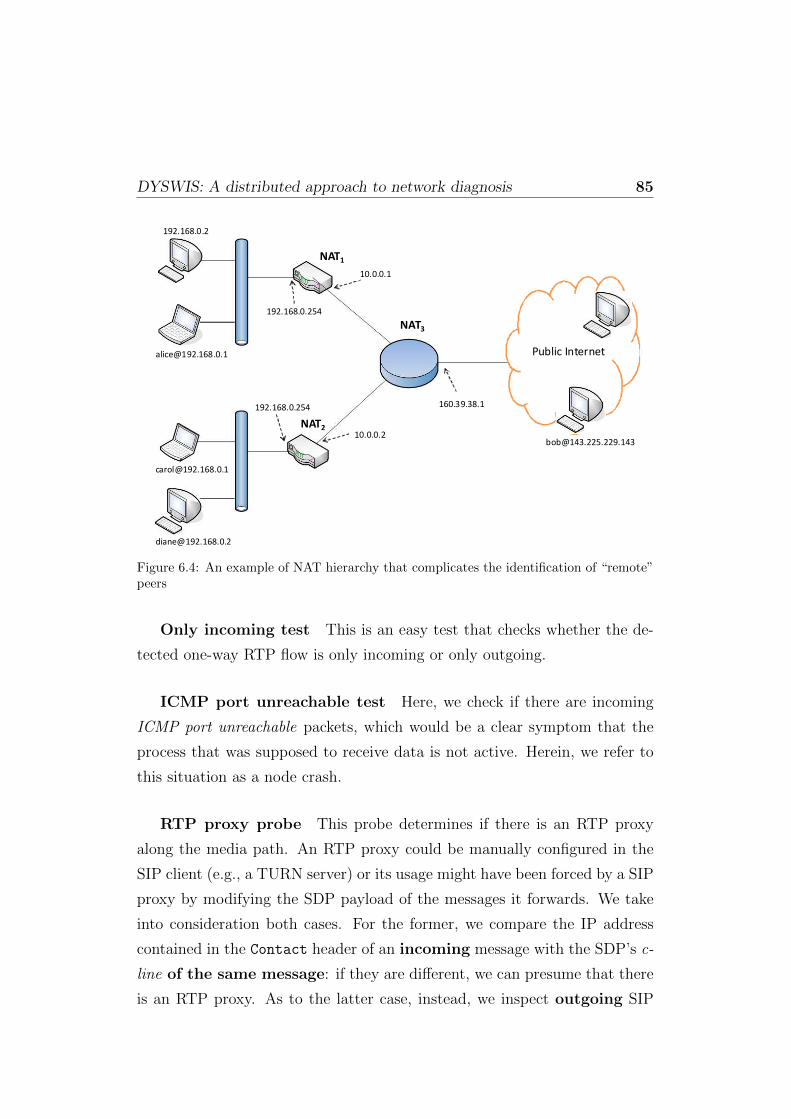
DYSWIS: A distributed approach to network diagnosis 85
Public Internet
NAT3
NAT2
NAT1
192.168.0.254
10.0.0.2
10.0.0.1
192.168.0.254
160.39.38.1
192.168.0.2
Figure 6.4: An example of NAT hierarchy that complicates the identification of “remote”peers
Only incoming test This is an easy test that checks whether the de-
tected one-way RTP flow is only incoming or only outgoing.
ICMP port unreachable test Here, we check if there are incoming
ICMP port unreachable packets, which would be a clear symptom that the
process that was supposed to receive data is not active. Herein, we refer to
this situation as a node crash.
RTP proxy probe This probe determines if there is an RTP proxy
along the media path. An RTP proxy could be manually configured in the
SIP client (e.g., a TURN server) or its usage might have been forced by a SIP
proxy by modifying the SDP payload of the messages it forwards. We take
into consideration both cases. For the former, we compare the IP address
contained in the Contact header of an incoming message with the SDP’s c-
line of the same message: if they are different, we can presume that there
is an RTP proxy. As to the latter case, instead, we inspect outgoing SIP

DYSWIS: A distributed approach to network diagnosis 86
packets, checking if the IP address contained in the SDP’s c-line is different
from both the local interface address and the reflexive IP address that is
retrieved by means of a STUN transaction.
Remote party up probe Whenever an RTP proxy is employed, we
are not capable to detect a possible crash of the remote node, since we would
not receive any ICMP packet. In these cases, we check the availability of the
remote party by sending a SIP OPTIONS message to it. Such message is sent
through all the SIP proxies included in the signaling path, if any, in order to
cross a possible remote NAT, making use of the Record-route and Route
SIP headers.
Local NAT test This test determines if the local node (i.e., the node
which experienced the fault) is behind a NAT by checking if the local interface
has a private IP address.
RTP port blocking This probe verifies that the port number used for
the RTP flow is not being blocked by a possible firewall running on the NAT
box.
STUN probe Here we determine if the local node is making use of
the STUN protocol. This probe consists in a STUN transaction to learn the
local reflexive IP address. The result is then checked against the address
contained in the SDP’s c-line of an outgoing SIP message.
Local/Remote ALG This probe consists of a direct call attempt to a
public DYSWIS node (i.e., a DYSWIS node that has a public IP address). As
long as this call attempt is performed without exploiting any NAT-traversal
technique, as well as without the SIP extension for Symmetric Response
Routing [29], it lets us detect if the local or remote NAT has built-in Appli-
cation Level Gateway functionality. In fact, the call attempt would succeed
only if the private IP address, inserted by the client in the SIP message, is
DYSWIS: A distributed approach to network diagnosis 87
being modified by the NAT element before forwarding it. As previously said,
we do not make use of the standard SIP ports for this call.
Direct call with STUN This probe differs from the previously de-
scribed one only because the call attempt employs the STUN protocol.
Same NAT probe The public (reflexive) IP of the remote party is
compared with the local reflexive address: if they match, the two parties are
assumed to be behind the same NAT.
Symmetric NAT probe One functionality offered by the STUN pro-
tocol is the possibility to discover which type of NAT (Full Cone, Restricted
Cone, Port Restricted Cone or Symmetric) is deployed. We use such feature
to determine if there is a symmetric NAT, that, as already introduced, might
be the cause of the fault we are trying to diagnose.
Remote NAT probe One of the main issues we had to face is the
detection of remote NAT elements. In other words, we wanted to learn if
the remote party is in a private network environment. Sometimes this is
easy because, parsing a received SIP message, we find a private IP address
(e.g., it could be in the SIP Contact, From or To headers, or in the SDP’s
c-line or o-line). Unfortunately, this depends on the specific implementation
of the SIP element: for instance, some clients, when using STUN, put their
public address in the SDP’s o-line, while others do not. Similarly, some
ALGs just parse outgoing messages and substitute every occurrence of a
private IP, while others perform better thought-out replacements. When
we cannot find any occurrence of private IP, we exploit a modified version
of the IP traceroute we developed on our own, that sends a SIP OPTIONS
message gradually increasing the IP Time-To-Live value. We send such
request towards the public IP address of the remote node and, if we get an
ICMP TTL exceeded packet whose source address is the original target of
our request, it is a clear indication of the presence of a remote NAT element.
DYSWIS: A distributed approach to network diagnosis 88
Otherwise, we could either receive a SIP response (e.g., a 200) or do not
receive any response at all. In the latter case, after having retried to send
the message, with the same TTL value, for a couple of times (to take care of
possible packet losses), we infer that there is a remote NAT box that is not
a Full Cone. Consequently, our SIP message is being filtered. Finally, if we
receive a response to the OPTIONS query, we cannot state there is no NAT
along the path, yet. In fact, in the standard specification [33], there is no
constraint for a NAT element to decrease the TTL value while forwarding
packets. This topic has been discussed a lot on the BEHAVE mailing list
of the IETF, where both personal opinions and implementation reports were
provided. It turned out that a NAT does not always decrease the TTL
of packets received on the public interface, while, for diagnostic reasons, it
always decreases it for packets generated in the private environment and
forwarded outside. Then, in order to take into account this possibility, when
we receive a response to the aforementioned SIP OPTIONS query, we check
the TTL value of the IP packet and try to infer whether it comes from a
end-host or it has been modified by a NAT. This check is performed by
considering that host operating systems have distinctive values for the initial
TTL. Then, if the packet did not go through a NAT, the received TTL value
would be equal to one of such initial TTL values, decreased by the number
of “hops” returned by the traceroute. Otherwise, we infer the presence of a
NAT. Further details of these OS-specific TTL values can be found in [20].
Remote DYSWIS node probe We conclude the description of the
probing functions by showing how we realized the selection of a DYSWIS
node that belongs to the same subnet of the remote party of the call. As
we already said, a selection merely based on the public IP address would
not be sufficient whenever there is a hierarchy of NATs. Then, after having
selected all the DYSWIS nodes characterized by the same public IP address
as the remote party, by means of the criterion described at the beginning of
Section 6.3.1, we need to verify if one (or more) of them can be exploited
DYSWIS: A distributed approach to network diagnosis 89
for our purposes. We achieve this goal by sending a SIP INFO message in
broadcast over the LAN. Such INFO message has to be sent within the dialog
existing between caller and callee, so that, according to the INFO’s RFC [11],
“A 481 Call Leg/Transaction Does Not Exist message MUST be sent by a
UAS if the INFO request does not match any existing call leg”. This is
achieved by making the node aware of the To and From tags and of the
Call-ID, so that it could be able to generate a request within a specific
dialog. Therefore, each selected node would receive a non-481 response only
if the remote party belongs to its same subnet.
Among all the methods envisaged by the SIP protocol, the only two that
MUST3 send an error response whenever they do not find any existing call
leg are INFO and UPDATE. We chose to exploit the first one because, even if it
is not mandatory, it is widely implemented in almost all the clients currently
available.
Validation
In this section we provide the results of our validation. We tested our work
with several different SIP clients. Specifically, we exploited the following soft-
phones: X-Lite (Windows), SJPhone (Windows and Linux), Ekiga (Linux)
and PJSIP-UA (Linux). As SIP and RTP proxies, we used OpenSIPS and
its RTPproxy component, respectively. Finally, we developed our own im-
plementation of a basic SIP ALG, since we could not find any suitable open-
source library. With all these components, we set up a distributed testbed
between the IRT lab at Columbia University and the COMICS lab at the
University of Napoli. For the sake of conciseness, we do not present all the
possible diagnosis paths that result from the flow chart in Fig. 6.3, which
nonetheless have all been tested. Instead, we just provide a couple of repre-
sentative scenarios, which show how the diagnosis process takes place.
3In the IETF jargon, the capitalized word “MUST” represents an absolute requirementof the specification.
DYSWIS: A distributed approach to network diagnosis 90
Scenario 1: problem with the local ALG The first scenario we
examine is characterized by the use of an ALG in the local network. We
deliberately modified our ALG library in order to induce the one-way RTP
fault. Specifically, we let our ALG function modify the c-line in the session-
level section of the SDP message, without changing the same parameter in the
media description section. So, since the session-level parameter is overridden
by an analogous one in the media description, if present, the remote party
will send its RTP packets to a private, non-routable, IP address.
In Fig. 6.5 we show a snippet of the whole flow diagram that applies to
this situation, whose understanding is quite straightforward. We just clarify
the last steps. The call attempted by the Local ALG probe can take place,
thus revealing the presence of an ALG. Though, the resulting RTP flow is still
one-way and this definitely represents a clue that the source of the problem
might be the ALG itself. Such conjecture is confirmed by the Direct call with
STUN probe. In fact, as long as we employ the STUN protocol before placing
the call, the ALG does not come into play, since there would be no private
IP addresses to replace.
Scenario 2: remote RTP proxy crash In this scenario, we suppose
that both caller and callee use an RTP proxy. If the proxy used by the remote
party crashes, the local DYSWIS node will experience a one-way RTP fault.
Furthermore, it will not see any incoming ICMP packet (see Fig. 6.6).
In Fig. 6.7 we show the diagnosis steps in this scenario. We are supposing
that the remote node is behind a non-symmetric NAT that has no built-in
ALG functionality. However, even changing such hypotheses, we are still
able to identify the cause of the fault. In general, when the diagnosis process
involves the remote subnet, the results of the various probing functions allow
us to narrow down the set of possible sources of the problem. In this case, we
first get ensured that the problem cannot be ascribed to a remote ALG; then,
we exclude that it could be somehow related to the remote NAT’s behavior,
since the SIP+STUN call involves two-way media flows. This brings us to

DYSWIS: A distributed approach to network diagnosis 91
Figure 6.5: Local ALG problem
Figure 6.6: Remote RTP proxy crash: network topology

DYSWIS: A distributed approach to network diagnosis 92
Figure 6.7: Remote RTP proxy crash: diagnosis flow
the final verdict. We observe that, in this lucky case, we are able to detect
the exact cause of the fault, while in other cases, when the network topology
is particularly complex, we are able to narrow down the fault space to two
possible choices.
6.3.4 Implementation details
In this section we provide some brief information about the implementation
choices. Besides Java, that has been chosen at the outset as the programming
language for the whole framework for its well known platform-independence
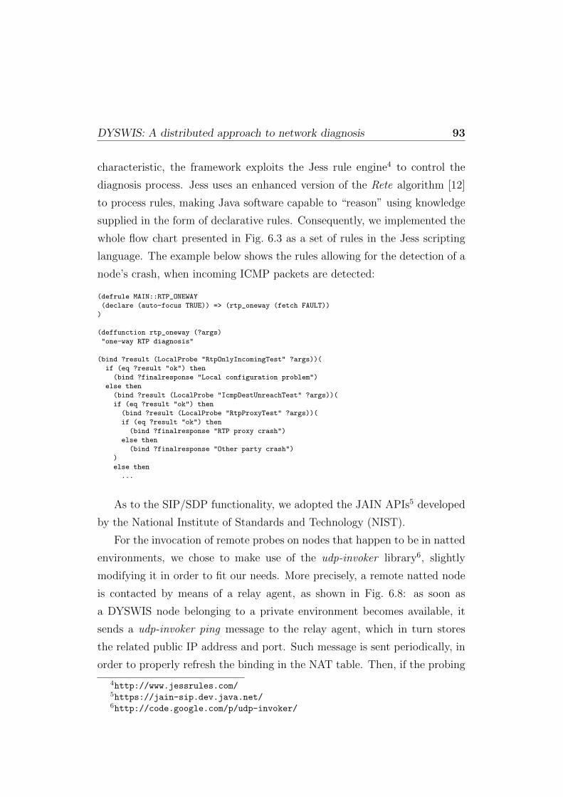
DYSWIS: A distributed approach to network diagnosis 93
characteristic, the framework exploits the Jess rule engine4 to control the
diagnosis process. Jess uses an enhanced version of the Rete algorithm [12]
to process rules, making Java software capable to “reason” using knowledge
supplied in the form of declarative rules. Consequently, we implemented the
whole flow chart presented in Fig. 6.3 as a set of rules in the Jess scripting
language. The example below shows the rules allowing for the detection of a
node’s crash, when incoming ICMP packets are detected:
(defrule MAIN::RTP_ONEWAY
(declare (auto-focus TRUE)) => (rtp_oneway (fetch FAULT))
)
(deffunction rtp_oneway (?args)
"one-way RTP diagnosis"
(bind ?result (LocalProbe "RtpOnlyIncomingTest" ?args))(
if (eq ?result "ok") then
(bind ?finalresponse "Local configuration problem")
else then
(bind ?result (LocalProbe "IcmpDestUnreachTest" ?args))(
if (eq ?result "ok") then
(bind ?result (LocalProbe "RtpProxyTest" ?args))(
if (eq ?result "ok") then
(bind ?finalresponse "RTP proxy crash")
else then
(bind ?finalresponse "Other party crash")
)
else then
...
As to the SIP/SDP functionality, we adopted the JAIN APIs5 developed
by the National Institute of Standards and Technology (NIST).
For the invocation of remote probes on nodes that happen to be in natted
environments, we chose to make use of the udp-invoker library6, slightly
modifying it in order to fit our needs. More precisely, a remote natted node
is contacted by means of a relay agent, as shown in Fig. 6.8: as soon as
a DYSWIS node belonging to a private environment becomes available, it
sends a udp-invoker ping message to the relay agent, which in turn stores
the related public IP address and port. Such message is sent periodically, in
order to properly refresh the binding in the NAT table. Then, if the probing
4http://www.jessrules.com/5https://jain-sip.dev.java.net/6http://code.google.com/p/udp-invoker/
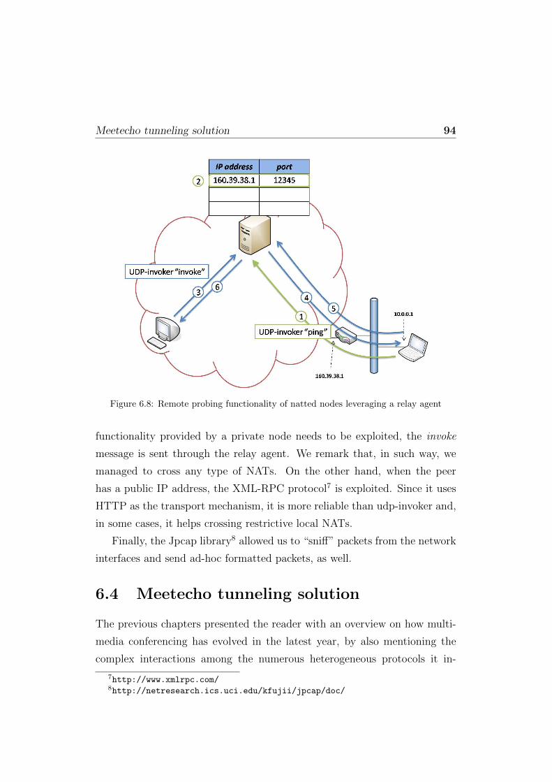
Meetecho tunneling solution 94
Figure 6.8: Remote probing functionality of natted nodes leveraging a relay agent
functionality provided by a private node needs to be exploited, the invoke
message is sent through the relay agent. We remark that, in such way, we
managed to cross any type of NATs. On the other hand, when the peer
has a public IP address, the XML-RPC protocol7 is exploited. Since it uses
HTTP as the transport mechanism, it is more reliable than udp-invoker and,
in some cases, it helps crossing restrictive local NATs.
Finally, the Jpcap library8 allowed us to “sniff” packets from the network
interfaces and send ad-hoc formatted packets, as well.
6.4 Meetecho tunneling solution
The previous chapters presented the reader with an overview on how multi-
media conferencing has evolved in the latest year, by also mentioning the
complex interactions among the numerous heterogeneous protocols it in-
7http://www.xmlrpc.com/8http://netresearch.ics.uci.edu/kfujii/jpcap/doc/

Meetecho tunneling solution 95
Client HTTP Tunnel
Client
HTTP Proxy
and/or Firewall
ServerHTTP Tunnel
Server
TCP/IP
connections
TCP/IP
connections
HTTP
Requests
HTTP
Requests
Figure 6.9: Generic HTTP tunnel
volves. Nevertheless, such protocols, despite being standards devised within
the context of international bodies like the IETF, often fail to work when
placed in real-world scenarios. In fact, as anticipated before, it is not unusual
for a user to belong to restrictive network environments where the commu-
nication with the public Internet is regulated by proxy elements which only
allow HTTP and/or HTTPS traffic to pass through. Solutions to effectively
deal with them have already been proposed and exploited with alternating
success during the years. Specifically, the most common approach that is ex-
ploited to get around such limitations is HTTP tunneling. This approach
basically consists in encapsulating a generic protocol (e.g., SSH) in valid
HTTP requests in order to allow such a protocol to travel across a network
it would not otherwise be able to work in. This is usually achieved by de-
ploying two entities into the network: (i) a tunneling server (acting as a web
server) on a publicly reachable machine, and (ii) a tunneling client (acting
as a web client) usually co-located with the protocol client which needs to
be tunneled. A diagram explaining how HTTP tunneling works is presented
in Fig. 6.9.
As it can be seen in the figure, the HTTP tunnel client acts as a server for
the generic protocol client, while the HTTP tunnel server acts as the actual
client for the generic protocol server. All the traffic is encapsulated by both
elements in legitimate HTTP requests, and thus succeeds in traversing the
installed HTTP Proxy/Firewall.
This approach is widely used; though, while it works fine for generic pro-
tocols like SSH or VNC, it raises issues when exploited to carry more sensitive
protocols like the ones involved in multimedia conferencing scenarios. In fact,

Meetecho tunneling solution 96
conferencing platforms often envisage the usage of several complex protocols
to achieve the functionality they are designed for. Meetecho, for instance,
makes use of many different standard protocols, namely CCMP for confer-
ence control, XMPP for instant messaging and notifications, SIP/SDP for
negotiating multimedia sessions, RTP to transport audio and video frames
in real-time, BFCP for moderation, specific protocols based on Java serializa-
tion features for what concerns white-boarding and desktop sharing, HTTP
for presentation sharing.
That said, the first issue that comes to mind is related to transport-aware
protocols like SIP and XMPP. In fact, as highlighted in Fig. 6.9, a tunnel
breaks the end-to-end communication between the client and the server: the
client sees the HTTP tunnel client as the actual server, while the server sees
the HTTP tunnel server as the actual client. This means that, whenever
transport-related information about the actual server and/or client is carried
within the tunneled protocol, things are likely not to work at all. For in-
stance, a SIP/SDP session would negotiate the wrong IPs/ports associated
with media channels, and as a consequence no RTP connection would be
established.
Besides, HTTP tunneling raises another issue related to real-time proto-
cols like RTP. In fact, RTP usually is transported over UDP, considering it
preferable for media packets to arrive soon rather than reliably. Neverthe-
less, HTTP is a TCP-based protocol, which means that encapsulated RTP
packets may suffer from delay when transported to their destination. This is
typically true whenever congestion control is involved.
Finally, considering almost all the protocols typically exploited within
the context of multimedia conferencing sessions are bi-directional and asyn-
chronous, ways have to be found to achieve a similar behavior on top of
HTTP as well, which by itself is instead a stateless, request/response proto-
col.
From an architectural viewpoint, the tunneling solution we devised for
Meetecho does not differ much from the typical HTTP tunneling solutions.

Meetecho tunneling solution 97
Meetecho
Participant
Tunnel
Client
Proxy /Firewall Meetecho
Server
Tunnel
Server
XMPP
SIP/SDP
RTP
...
XMPP
SIP/SDP
RTP
...
Encapsulated
protocols
Figure 6.10: Meetecho HTTP tunnel
In fact, our approach is based on a client-server architecture, where the
client and the server communicate with each other and take care of han-
dling both the HTTP-based transport and the multiplexing/demultiplexing
of the Meetecho protocols. An example is presented in Fig. 6.10. While
the client is assumed to be co-located with the generic Meetecho participant
(i.e. the client of our conferencing architecture), the server needs to be placed
somewhere publicly reachable, in order to act as a web server that all clients,
no matter how restrictive their reference proxy or firewall is, can reach via
HTTP/HTTPS. As anticipated when describing the generic tunneling solu-
tions, the Meetecho Participant assumes the tunnel client is the Meetecho
Conferencing Server, while in turn the Meetecho Conferencing Server must
think that the exploited tunnel server is the Participant itself. This means
that the Participant does not login at the actual server, but at the tunnel
client acting as a proxy for all the protocols involved in a multimedia con-
ference. As a consequence, the Participant does not need to be aware of any
tunneling being exploited: it can just assume the server is on a local address
(i.e., the tunnel client), and the framework will do the rest.
To make this work, it is quite obvious that protocol rewriting may be
involved. In fact, both the Tunnel Client and Server act as proxies/bridges
for all the protocols. Since, as we already anticipated, some of these protocols
are sensitive to transport-related information, proper care must be devoted
to them, since a blind encapsulation would likely cause them to fail.
All protocols are encapsulated in one virtual channel: proper multiplexing
and de-multiplexing is achieved by means of an ad-hoc protocol we devised
ourselves. This protocol also takes care of additional functionality that may

Meetecho tunneling solution 98
Figure 6.11: Meetecho HTTP tunnel attempts: Flow Diagram
be required, like tunneling authentication, bandwidth monitoring/shaping of
the managed sub-protocols, keep-alive mechanisms to avoid the underlying
HTTP transport channel to be shut down, and so on.
In the following two subsections we will describe the HTTP transport
approaches and how we encapsulated all the involved protocols, respectively.
6.4.1 Transport
As anticipated, we assume a single virtual channel is used to encapsulate
all the protocols. Hence, we need a way to transport such a virtual channel
over HTTP. In our architecture, we devised three different transport modes:
(i) HTTPS, (ii) HTTP CONNECT, and (iii) HTTP encapsulation. The
actual mode to be used changes according to the limitations enforced on
the available network infrastructure, as it will be explained in the following
subsections. A diagram depicting the sequence of encapsulation attempts is
presented in Fig. 6.11
HTTPS
The first mode is HTTPS. The tunnel client tries to connect to the tun-
nel server via the well-known port number 443. In this mode, a single TLS
connection is set up between the tunnel client and the tunnel server, since
TLS encryption allows for the actual content of the connection to be hidden
Meetecho tunneling solution 99
from the active proxy/firewall. This allows our framework to avoid making
use of actual HTTP, but rather exploit our multiplexing/demultiplexing pro-
tocol encrypted in TLS. Pre-shared fingerprints are used to avoid potential
man-in-the-middle issues. In fact, it may happen that HTTPS is allowed to
pass by the proxy, but with the proxy itself acting as a man-in-the-middle to
enforce some kind of payload inspection in order to make sure that the con-
tent is actually HTTP. Such a scenario would be detected by our platform,
considering the fingerprint matching process would fail.
Considering the protocol contents are hidden, by relying on this mode
of operation we can use the same connection both in transmission and in
reception. In fact, we do not need to take into account the nature of HTTP,
which means this mode is implementing a ‘fake’ HTTPS connection.
HTTP CONNECT
In case the fake HTTPS approach fails (either because the 443 port is blocked,
or because the fingerprints do not match), the tunnel client tries the second
mode, namely HTTP CONNECT.
CONNECT is a legitimate HTTP command which allows for the conver-
sion of an HTTP request connection to a completely transparent TCP/IP
tunnel. An example is the following:
CONNECT realserver.example.net:443 HTTP/1.1
Host: proxy.example.com:80
by which a client requests the forwarding of the present HTTP connection
(between the client and the proxy) to a different server at a different port.
This was originally needed in order to instantiate HTTPS connections
through HTTP proxies which did not make use of encryption. Nevertheless,
since then many proxies disabled, or at least limited, support for CONNECT,
considering it raised several security concerns. In fact, in the absence of
further constraints every application could use HTTP CONNECT to carry
a completely different protocol than HTTPS. As a consequence, the proxies

Meetecho tunneling solution 100
that still accept CONNECT requests usually only allow it when the requested
address is for a well known service, e.g., port 80 or 443.
That said, that is exactly what the tunnel client tries to do in case di-
rect HTTPS fails: it tries to request from the proxy the creation of a new,
still fake, HTTPS connection towards the tunnel server. Should the request
succeed, everything happens just as if direct HTTPS were exploited.
HTTP Encapsulation
In case both the previous modes failed for any reason, we devised a third
mode for the transport of the virtual channel. This mode is actual HTTP
encapsulation. By using this mode, the tunnel client tries to connect to the
tunnel server at port 80. If successful, actual HTTP messages are exchanged
between client and server, meaning that HTTP headers and body are prop-
erly constructed.
Of course, some measures are taken in order to avoid problems. First of
all, all the requests include headers to disable caching, in order to avoid any
proxy to provide the client or the server with obsolete content after a request.
Furthermore, since the content to be transported is not HTML but binary
content, the Content-Type header must be manipulated as well in order not
to have the proxy drop the request. We chose to simulate the transmis-
sion of JPEG images. Finally, two separate, yet logically linked connections
are actually used to implement the asynchronous behavior needed by the
virtual channel over the actual HTTP interaction. Specifically, the client is-
sues two parallel HTTP requests: (i) an HTTP GET, to receive messages
from the server, and (ii) an HTTP POST, to send messages to the server.
Random Content-Length headers are chosen, in order to simulate different
requests. As soon as all the data corresponding to a specific length have been
sent/received, a new POST/GET is sent to keep the connection alive.
This approach has the disadvantage of bringing more overhead, consider-
ing additional encoding on the data is needed (in our case, we chose a Base64
encoding) and two separate connections need to be properly synchronized.

Meetecho tunneling solution 101
However, this solution is the one more likely to succeed in the most restrictive
scenarios, as confirmed by our experimental tests.
6.4.2 Protocols Handling
Whatever mode is exploited, what is transported is the same virtual channel.
This channel acts as a virtual container for all the involved protocols, which
are multiplexed (and de-multiplexed accordingly) at the application level. We
also devised a solution able to cope with the co-existence of more instances
of the same protocol in the same virtual channel, as in the case, for instance,
of RTP, for which we might have a first connection dedicated to the audio
stream and a second one devoted to video.
As anticipated at the beginning of this section, just encapsulating these
protocols onto the virtual channel may not be enough in some cases. In fact,
while protocols like CCMP, BFCP, RTP and (partly) HTTP can be blindly
forwarded through the virtual channel without hassle, the same cannot be
said for other protocols that are aware of the underlying transport informa-
tion, as in the case of XMPP, SIP/SDP and Java serialization-based protocols
(used by the white-boarding and desktop sharing modules in Meetecho).
These protocols are sensitive to some transport-level parameters that
might be carried as part of their payload and hence call for proper manip-
ulation and rewriting in order to work in a scenario like the one introduced
by tunneling, which clearly violates the end-to-end principle.
XMPP
XMPP is used in Meetecho for several purposes. In fact, despite being a
widely spread instant messaging protocol with support for Multi User Chat
(i.e., conference rooms), it is also easily extensible with additional features
(like notifications, voting/polling, dynamic negotiation of features, etc.) that
make it the perfect candidate for conferencing-related functionality.
That said, XMPP is partly aware of the network it is deployed on. Specif-
ically, domains and IP addresses play a strong role in XMPP, since they are
Meetecho tunneling solution 102
part of the To and From fields of all requests, responses and events. In order
not to suffer from the tunneling encapsulation, the domain part of all these
fields needs to be properly rewritten, since the tunnel client and the tunnel
server act as entry and exit points for the XMPP communication with the
participant and the conferencing server, respectively.
Besides, as we already said, in the Meetecho platform XMPP is also
used to dynamically negotiate some of the additional functionality provided.
It is the case, for instance, of presentation sharing and desktop sharing.
These features, while implemented by means of other protocols, are actually
negotiated within the context of XMPP requests. This means that these
requests need to be manipulated as well, so that the tunnel client can deploy
virtual servers to act as bridges for those protocols as well, in place of the
unreachable real servers.
SIP/SDP
SIP and SDP are widely deployed protocols devoted to the negotiation of
multimedia sessions. They are the most commonly used protocols in VoIP
scenarios. For this reason, since the beginning they have been chosen as the
perfect candidates for the multimedia functionality in a standard conferenc-
ing environment like Meetecho.
They both are strongly aware of transport information, and as such very
sensitive to anything that could interfere with it (e.g., NAT issues, etc.).
Transport-related information, in fact, can be found in many of the headers
in SIP, and in the negotiation lines of SDP. For this reason, all these fields
and lines need proper rewriting in order to take care of the protocol bridging.
For what concerns SIP, the REGISTER message needs additional care,
considering the negotiated DIGEST includes the involved addresses.
For what concerns SDP, instead, all that is needed is a proper rewriting
of the media lines, in order to create RTP bridges accordingly.
Meetecho tunneling solution 103
Java Serialization
Java Serialization is a technique commonly used in several network projects
based on Java. It basically consists in a mechanism by which native Java
objects can be converted in a binary format, for instance in order to be
transmitted over a network stream, and converted back to native Java objects
once they reach their destination. Such technique is used in our conferencing
platform for two main functions: shared whiteboard (jSummit) and desktop
sharing (jrdesktop).
By itself, Java Serialization is not a network protocol, and as such it is
not sensitive to transport-related information. Nevertheless, protocols can
be built on top of it, as is the case of Java Remote Method Invocation (Java
RMI) and the aforementioned Meetecho features. Whenever such protocols
include the manipulation of objects which contain addresses and/or ports in
order to work correctly, they become sensitive to tunneling. This is exactly
the case of both jSummit and jrdesktop.
In order to make them work despite the tunneling, we had to implement a
proper manipulation of the protocol contents. This included low-level manip-
ulation of the serialized objects in the streams, making sure they remained
coherent and decodable at the destination (e.g., enlarging/restricting pay-
loads when necessary in order to avoid exceptions).
6.4.3 Experimentations
This section presents a brief overview of the experimental results we obtained
from the implementation of our approach. We both show how we verified
the capability to deal with restrictive network environment, and report some
performance figures we devised.
Proxy/firewall traversal
In order to simulate a restrictive component on the network, we deployed
a generic PC equipped with a Linux distribution (Debian GNU/Linux 5.0)
in our testbed, to act as either a firewall or a more or less restrictive proxy.

Meetecho tunneling solution 104
We made use of well known open source tools to implement these behaviors,
namely IPtables for the firewall functionality, Apache HTTPD as a generic
HTTP proxy and Squid as both an explicit and a transparent HTTP proxy.
To make sure all the traffic coming from the participant would need to
pass through our component in order to reach the server, we configured the
PC as a Linux Router, and then explicitly set it as the default gateway for
our test participant.
For what concerns the firewalling functionality, we prepared a series of
increasingly restrictive IPtables rules to enforce on such a machine, in order
to filter the traffic handled by the proxy accordingly. This allowed us to
force a test of all the three transport modes previously introduced, namely
HTTPS, CONNECT and HTTP.
To test the first mode, the first rule we envisaged was to only allow HTTP
and HTTPS traffic through the proxy. This, translated to IPtables words,
means we needed to prepare a rule to only allow incoming TCP connection
on the well-known ports used by those two protocols, i.e., 80 and 443, as
shown below.
iptables -I FORWARD 1 -p tcp -m multiport --dports 80,443
-j ACCEPT
iptables -I FORWARD 2 -m state --state ESTABLISHED,RELATED
-j ACCEPT
iptables -I FORWARD 3 -j DROP
In this first setup, only IPtables was configured, while neither the Apache
web server nor the Squid proxy were active.
We verified that, under these restrictions, the Tunnel Client was able to
reach the Tunnel Server using the fake HTTPS operation mode, and allowed
its related participant to successfully join a multimedia conference. In fact,
as explained, the fake HTTPS has the Tunnel Client connect at the Tunnel
Server at port 443, thus simulating a HTTPS connection and circumventing
the IPtables rule. Of course, considering such an experiment only envisaged
a blind port-filtering mechanism to be in place, it was assumed to work fine

Meetecho tunneling solution 105
anyway. In fact, whenever ports alone are used to filter traffic, these rules
are easily circumventable.
After this trivial experiment, we chose to enforce a stricter restriction on
the allowed connections, in order to test the second mode as well. We first
removed the 443 port from the previous rule, thus limiting the allowed traffic
to HTTP only:
iptables -I FORWARD 1 -p tcp -m multiport --dports 80 -j ACCEPT
This time, nevertheless, we also deployed an Apache HTTPD Web Server
in order to add support for the HTTP CONNECT to our proxy component.
To do so, we added the following lines to the HTTPD configuration:
<IfModule mod_proxy.c>
ProxyRequests On
AllowCONNECT 443
[..]
which allowed HTTPD to act as a proxy, but only for requests directed
to a server at port 443, thus limiting the proxy functionality to HTTPS only.
As expected, this time the fake HTTPS mode was not successful: in fact, the
IPtables rule did forbid any connection attempt to any port different than
80, and so 443 made no difference. As a consequence, the Tunnel Client tried
the next mode, i.e., HTTPS via CONNECT. Having explicitly configured the
application to use our proxy component as HTTP proxy of the network, the
Tunnel Client successfully managed to reach the Tunnel Server: in fact, first
of all the request was addressed to a server listening on port 80 (HTTPD),
thus circumventing the limitation imposed by IPtables. Besides, the request
was an HTTP CONNECT request to reach the Tunnel Server at port 443:
this was allowed by our restriction on the proxy functionality in the HTTPD
configuration, and as a consequence the Tunneling worked fine as well.
Having verified that the Apache web server supported our request, we
chose to also test the second mode using a more strict component as the
Squid proxy. Squid is a well known open source component, and it is the most

Meetecho tunneling solution 106
commonly deployed component whenever caching and proxying functionality
are required for HTTP. That said, we disabled Apache and launched Squid
as an explicit proxy instead. The support for CONNECT, as before, was
limited for port 443 alone, which in Squid words is translated like that:
acl SSL_ports port 443
acl CONNECT method CONNECT
http_access deny CONNECT !SSL_ports
Even in this scenario, the second mode of operation was successful: the
Tunnel Client was able to request the creation of an encrypted connection
towards the Tunnel Server by means of the CONNECT method, and the ses-
sion went on as expected. This confirmed us that the approach we employed
was correct and effective for such a need.
To test the last and more delicate mode, we removed the support for the
CONNECT method from our testbed scenario. Maintaining the previous
IPtables rules enforcements, we also changed the default Squid behavior, by
making it act as a transparent HTTP proxy rather than an explicit one: this
means that we wanted all HTTP traffic to be intercepted and manipulated
by Squid without any configuration needed on the client side, making all
clients unaware of any proxy/cache being in place. In order to do so, we first
configured Squid as a transparent proxy:
http_port 3128 transparent
always_direct allow all
Then, we also configured a proper IPtables rule to forward all requests
addressed to port 80 to port 3128 instead (the default port used by Squid), in
order to actually redirect all the HTTP traffic passing through our component
to Squid to have it managed accordingly.
iptables -t nat -A PREROUTING -i eth1 -p tcp --dport 80 -j DNAT
--to 192.168.1.1:3128
iptables -t nat -A PREROUTING -i eth0 -p tcp --dport 80
-j REDIRECT --to-port 3128

Meetecho tunneling solution 107
We then launched the experiment again. As expected, the first two
modes both failed: HTTPS on port 443 was blocked by IPtables, and no
HTTPS proxying functionality was available to attempt an HTTP CON-
NECT bridged connection. The third mode, instead, worked flawlessly: in
fact, such mode assumes two HTTP connections are set up towards the Tun-
nel Server at port 80, thus successfully traversing the IPtables limitations.
Besides, Squid successfully recognized both the connections as valid HTTP
traffic, and redirected the traffic to the Tunnel Server according to its busi-
ness logic.
RTP over TCP performance assessment
The transmission of real-time media flows usually leverages the UDP proto-
col to transport RTP packets. In fact, a reliable transmission might be in-
appropriate for delay-sensitive data, since retransmissions increase delay and
congestion control mechanisms affect the transmission rate. We presented,
instead, a tunneling solution that exploits the HTTP protocol (which works
over TCP connections) to carry RTP packets, too. In this subsection we
present the results of the tests we performed in order to assess the perfor-
mance of the proposed approach. We exploited our Meetecho conferencing
platform to evaluate the delay that characterizes the RTP connections, ei-
ther when no tunneling solution is in place or when the Meetecho tunneling
solution is employed. More precisely, we focused on the delay jitter, which
is known as the key performance indicator of real-time communication chan-
nels. Fig. 6.12-a shows the time evolution of the jitter, as regards an audio
RTP channel relying on the UDP protocol. Fig. 6.12-b, instead, depicts the
jitter evolution when tunneling is employed in an uncongested network envi-
ronment, which is very similar to the previous one.
Finally, Fig. 6.13 shows how tunneling affects the performance when a
heavy network congestion occurs: in this scenario the trend is more irregu-
lar, reflecting the further delay introduced by TCP congestion control mech-
anism. Anyway, from a qualitative perspective, such delay did not lead to
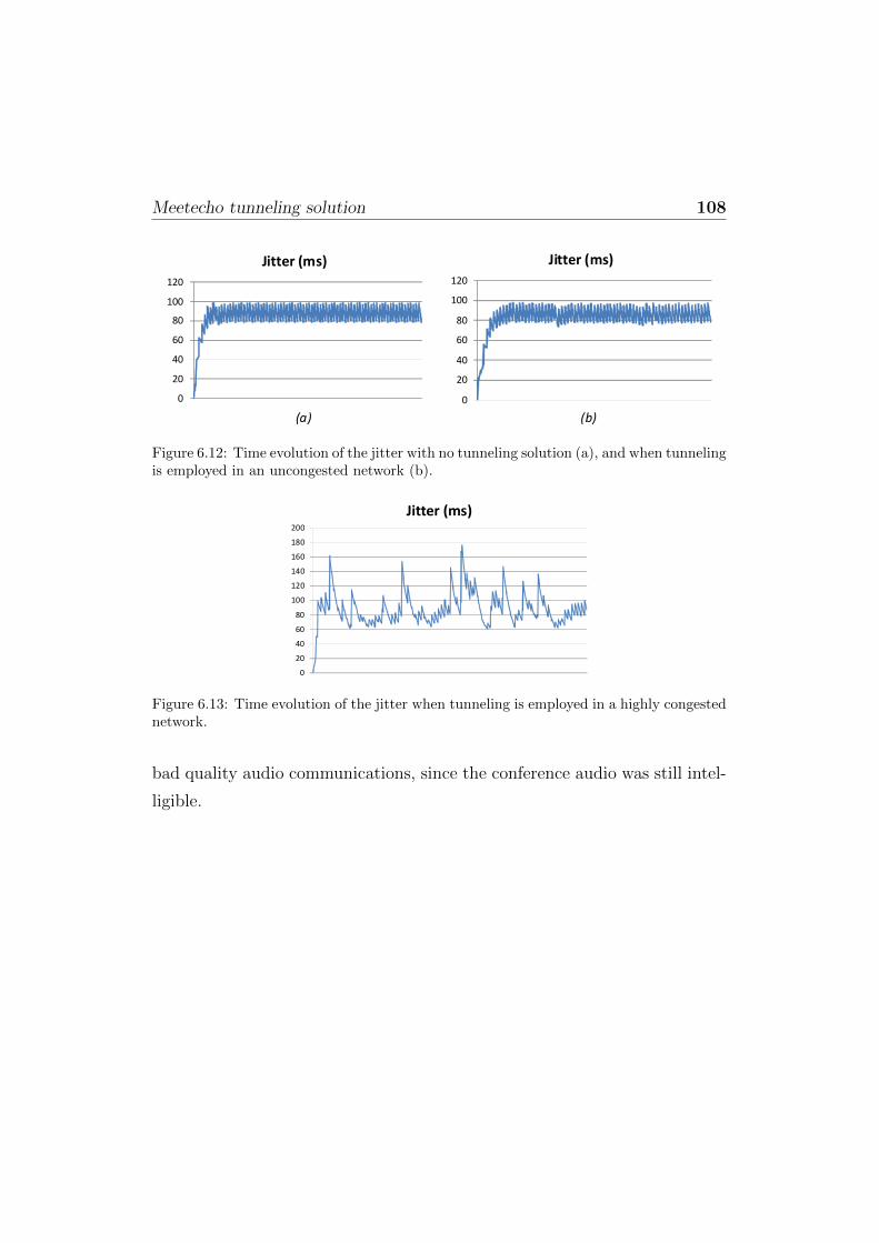
Meetecho tunneling solution 108
0
20
40
60
80
100
120
Jitter (ms)
0
20
40
60
80
100
120
Jitter (ms)
(a) (b)
Figure 6.12: Time evolution of the jitter with no tunneling solution (a), and when tunnelingis employed in an uncongested network (b).
0
20
40
60
80
100
120
140
160
180
200
Jitter (ms)
Figure 6.13: Time evolution of the jitter when tunneling is employed in a highly congestednetwork.
bad quality audio communications, since the conference audio was still intel-
ligible.

Chapter 7
Conclusions
The work carried out during the last three years as Ph.D. Student has been
focused on the multimedia conferencing service over next-generation IP net-
works. The ultimate goal was to design an architecture having high scalabil-
ity requirements, while taking into account the outcome of the standardiza-
tion efforts conducted by the Internet Engineering Task Force.
Fig. 7.1 depicts a progressive workflow, with the three main milestones
met: centralized conferencing, distributed conferencing and troubleshooting.
As to the former, we thoroughly examined the state of the art, pointing
the attention on the standardization efforts the conferencing service was going
through (see Chapter 1). Moreover, I actively contributed to the definition
of the state of the art itself, by actively participating to the activities carried
out within the XCON and MEDIACTRL Working Groups of the IETF. In
such context, reference testbeds implementing the specified frameworks and
protocols have been realized, as well as call flow documents which are on the
path to become Informational RFCs. The output of the XCON-related work
has been Meetecho, a standards-compliant multimedia conferencing architec-
ture which also leverages the MEDIACTRL approach as a first step towards
scalability (see Chapter 2 and Chapter 3).
After the work upon the Meetecho centralized platform has been com-
pleted, we started investigating a possible evolution of the XCON framework
towards distributed environments. We came up with the DCON (Distributed

110
Nov. 2007 Nov. 2008 Nov. 2009 Nov. 2010
Centralized conferencing
• State of the art analysis
• Contribution to standardization activities conducted by XCON and MEDIACTRL WGs
• Reference testbeds implementing the specified frameworks and involvedprotocols
• Call flow documents to be publishedas Informational RFCs
• Meetecho: a standard centralizedconferencing architecture
• XCON- and MEDIACTRL-compliant
• Several additional functionalityintroduced
Distributed conferencing
• DCON proposal
• Requirements identification
• Design of a distributed conferencingframework
• Prototype implementation byextending the Meetecho platform
• XCON vs. DCON: scalability analysis
Troubleshooting
• DYSWIS: a distributedarchitecture for network fault diagnosis
• A tunneling architecture for multimedia conferencing scenarios
Figure 7.1: Progressive workflow
Conferencing) proposal, which envisages a distributed architecture where a
number of XCON-compliant “islands” are interconnected through an over-
lay network (see Chapter 4). DCON has been implemented extending the
Meetecho platform, which we also used as a term of comparison while evalu-
ating performance figures. The experimental campaign we conducted proved
how the migration towards distributed environments definitely improves the
scalability of the overall system (see Chapter 5).
Finally, the last milestone is related to troubleshooting. In fact, when we
brought the results of our research activities from the lab to the real world,
a number of issues arose. Such issues have been identified and solved by
means of a network diagnosis architecture and a protocol tunneling solution,
respectively (see Chapter 6).
Bibliography
[1] 3GPP2. Conferencing using the IP Multimedia (IM) Core Network (CN)subsystem; Version 1.0). Technical report, 3GPP, May 2007.
[2] A. Amirante, T. Castaldi, L. Miniero, and S. P. Romano. Improving thescalability of an IMS-compliant conferencing framework through pres-ence and event notification. In Proceedings of the 1st International Con-ference on Principles, Systems and Applications of IP Telecommunica-tions (IPTComm), New York City, NY , USA, July 2007.
[3] A. Amirante, T. Castaldi, L. Miniero, and S. P. Romano. Recordingand playout of multimedia conferencing sessions: a standard approach.In Lecture Notes in Computer Science - Future Multimedia Networking(FMN) 2010, pages 63–74. Springer-Verlag, June 2010.
[4] A. Amirante, T. Castaldi, L. Miniero, and S. P. Romano. Media ControlChannel Framework (CFW) Call Flow Examples. draft-ietf-mediactrl-call-flows, October 2010 (work in progress).
[5] M. Barnes, C. Boulton, and O. Levin. A Framework for CentralizedConferencing. RFC5239, June 2008.
[6] M. Barnes, C. Boulton, S. P. Romano, and H. Schulzrinne. CentralizedConferencing Manipulation Protocol. draft-ietf-xcon-ccmp, July 2010(work in progress).
[7] C. Boulton, T. Melanchuk, and S. McGlashan. Media Control ChannelFramework. draft-ietf-mediactrl-sip-control-framework, September 2010(work in progress).
[8] C. Boulton and L. Miniero. Media Resource Brokering. draft-ietf-mediactrl-mrb, October 2010 (work in progress).
[9] G. Camarillo. Session Description Protocol (SDP) Format for BinaryFloor Control Protocol (BFCP) Streams. RFC4583, November 2006.

BIBLIOGRAPHY 112
[10] G. Camarillo, J. Ott, and K. Drage. The Binary Floor Control Protocol(BFCP). RFC4582, November 2006.
[11] S. Donovan. The SIP INFO Method. RFC 2976, October 2000.
[12] Charles Forgy. Rete: A fast algorithm for the many pattern/many objectpattern match problem. Artificial Intelligences, 19(1):17–37, 1982.
[13] ITU-T. Gateway control protocol: Version 3. ITU-T RecommendationH.248.1, May 2006.
[14] P. Matthews J. Rosenberg, R. Mahy and D. Wing. Requirements forDistributed Conferencing. draft-romano-dcon-requirements, June 2010(work in progress).
[15] R. Mahy J. Rosenberg and P. Matthews. Session Traversal Utilities forNAT (STUN). RFC 5389, October 2008.
[16] A. Johnston and O. Levin. Session Initiation Protocol (SIP) Call Control- Conferencing for User Agents. RFC4579, August 2006.
[17] S. McGlashan, T. Melanchuk, and C. Boulton. A Mixer Control Packagefor the Media Control Channel Framework. draft-ietf-mediactrl-mixer-control-package, February 2010.
[18] S. McGlashan, T. Melanchuk, and C. Boulton. An Interactive Voice Re-sponse (IVR) Control Package for the Media Control Channel Frame-work. draft-ietf-mediactrl-ivr-control-package, February 2010 (work inprogress).
[19] T. Melanchuk. An Architectural Framework for Media Server Control.RFC5567, June 2009.
[20] T. Miller. Passive OS Fingerprinting: Details and Techniques.
[21] O. Novo, G. Camarillo, D. Morgan, and J. Urpalainen. ConferenceInformation Data Model for Centralized Conferencing (XCON). draft-ietf-xcon-common-data-model, May 2010 (work in progress).
[22] J. Postel and J. Reynolds. File Transfer Protocol (FTP). RFC959,October 1985.
[23] A. Roach. Session Initiation Protocol (SIP) - Specific Event Notification.RFC2543, June 2002.

BIBLIOGRAPHY 113
[24] S. P. Romano, A. Amirante, T. Castaldi, L. Miniero, and A. Buono.A Framework for Distributed Conferencing. draft-romano-dcon-framework, June 2010 (work in progress).
[25] S. P. Romano, A. Amirante, T. Castaldi, L. Miniero, and A. Buono.Requirements for Distributed Conferencing. draft-romano-dcon-requirements, June 2010 (work in progress).
[26] S. P. Romano, A. Amirante, T. Castaldi, L. Miniero, and A. Buono.Requirements for the XCON-DCON Synchronization Protocol. draft-romano-dcon-xdsp-reqs, June 2010 (work in progress).
[27] J. Rosenberg. A Framework for Conferencing with the Session InitiationProtocol (SIP). RFC4353, February 2006.
[28] J. Rosenberg. Interactive Connectivity Establishment (ICE): A Proto-col for Network Address Translator (NAT) Traversal for Offer/AnswerProtocols. RFC-to-be 5245, February 2010.
[29] J. Rosenberg and H. Schulzrinne. An extension to the session initiationprotocol (sip) for symmetric response routing. RFC 3581, August 2003.
[30] J. Rosenberg, H. Schulzrinne, G. Camarillo, et al. SIP: Session InitiationProtocol. RFC3261, June 2002.
[31] J. Rosenberg, H. Schulzrinne, and O. Levin. A Session Initiation Proto-col (SIP) Event Package for Conference State. RFC4575, August 2006.
[32] P. Saint-Andre. Extensible Messaging and Presence Protocol (XMPP):Core. RFC3920, October 2004.
[33] P. Srisuresh and K. Egevang. Traditional IP Network Address Translator(Traditional NAT). RFC 3022, January 2001.
[34] W3C. Synchronized Multimedia Integration Language (SMIL 2.0)).http://www.w3.org/TR/SMIL2/.
[35] D. Yon and G. Camarillo. TCP-Based Media Transport in the SessionDescription Protocol (SDP). RFC4572, September 2005.