Embed Size (px)
Citation preview
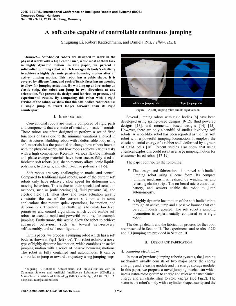
Abstract— Soft-bodied robots are designed to work in the physical world with a high compliance, while most of them lack in highly dynamic motion. In this paper, we present a soft-bodied jumping robot, which leverages its body’s elasticity to achieve a highly dynamic passive bouncing motion after an active jumping motion. This robot has a cubic shape. It is covered by silicone foam, and each of its six faces has an opening to allow for jumping actuation. By winding up and releasing an elastic strip, the robot can jump in two directions at any orientation. We present the design, and fabrication process, and experimental results. By comparing this robot with a rigid version of the robot, we show that this soft-bodied robot can use a single jump to travel longer forward than its rigid counterpart.
I. INTRODUCTION
Conventional robots are usually composed of rigid parts and components that are made of metal and plastic materials. These robots are often designed to perform a set of fixed functions or tasks due to the minimal variations allowed in their structures. Building robots with a deformable body using soft materials has the potential to change how robots interact with the physical world, and how robots achieve various tasks with a high compliance. Recently, various flexible materials and phase-change materials have been successfully used to fabricate soft robots (e.g. shape-memory alloys, ionic liquids, polymers, hydro gels, and electro-active polymers) [1-5].
Soft robots are very challenging to model and control. Compared to traditional rigid robots, most of the current soft robots only have relatively slow speed for deforming and moving behaviors. This is due to their specialized actuation methods, such as joule heating [6], fluid pressure [4], and electric field [7]. Their slow and weak actuation greatly constrains the use of the current soft robots in some applications that require quick operations, locomotion, and deformations. Therefore, the challenge is to create low level primitives and control algorithms, which could enable soft robots to execute rapid and powerful motions, for example jumping. Furthermore, this would allow the robot to achieve advanced behaviors, such as toward self-recovery, self-assembly, and self-reconfiguration.
In this paper, we propose a jumping robot which has a soft body as shown in Fig.1 (left side). This robot exhibits a novel type of highly dynamic locomotion, which combines an active jumping motion with a series of passive bouncing motions. The robot is fully contained and autonomous. It can be controlled to jump or toward a trajectory using jumping steps.
Shuguang Li, Robert K. Katzschmann, and Daniela Rus are with the
Computer Science and Artificial Intelligence Laboratory (CSAIL) at Massachusetts Institute of Technology (MIT), Cambridge, MA 02139, USA, {lisg, rkk, rus}@csail.mit.edu
Several jumping robots with rigid bodies [8] have been developed using spring-based designs [9-12], fluid powered designs [13], and momentum-based designs [14] [15]. However, there are only a handful of studies involving soft robots. A wheel-like robot has been reported as the first soft robot with a powerful jumping locomotion. It employs the elastic potential energy of a rubber shell deformed by a group of SMA coils [16]. Recent studies also show that using chemical explosions could result in a large jumping motion for elastomer-based robots [17-19].
The paper contributes the following:
· The design and fabrication of a novel soft-bodied jumping robot using silicone foam. Its compact jumping mechanism is realized by winding up and releasing elastic strips. The on-board micro controller, battery, and sensors enable the robot to jump autonomously.
· A highly dynamic locomotion of the soft-bodied robot through an active jump and a passive bounce that can be continuously repeated. The soft robot’s jumping locomotion is experimentally compared to a rigid robot.
The design details and the fabrication process for the robot are presented in Section II. The experiments and results of 2D and 3D jumping are provided in Section III.
II. DESIGN AND FABRICATION
A. Jumping Mechanism In most of previous jumping robotic systems, the jumping
mechanism usually consists of two major parts: the energy charging and releasing module and the energy storage module. In this paper, we propose a novel jumping mechanism which uses a stator-rotor system to charge and release the mechanical energy and an elastic strip to store energy (see Fig.2). The stator is the robot’s body with a cylinder-shaped cavity and the
A soft cube capable of controllable continuous jumping Shuguang Li, Robert Katzschmann, and Daniela Rus, Fellow, IEEE
Figure 1. A soft jumping robot and its rigid version
2015 IEEE/RSJ International Conference on Intelligent Robots and Systems (IROS)Congress Center HamburgSept 28 - Oct 2, 2015. Hamburg, Germany
978-1-4799-9994-1/15/$31.00 ©2015 IEEE 1712
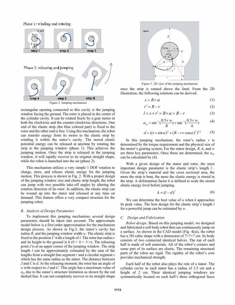
rectangular opening connected to this cavity is the jumping window facing the ground. The rotor is placed in the center of the cylinder cavity. It can be rotated freely by a gear motor in both the clockwise and the counter-clockwise directions. One end of the elastic strip (the blue colored part) is fixed to the rotor and the other end is free. Using this mechanism, the robot can transfer energy from its motor to the elastic strip by winding it within the stator’s cavity. The stored elastic potential energy can be released at anytime by rotating the strip to the jumping window (phase 1). This achieves the jumping motion. Once the strip is released in the jumping window, it will rapidly recover to its original straight shape, while the robot is launched into the air (phase 2).
This mechanism utilizes a very simple 1 DOF rotation to charge, store, and release elastic energy for the jumping motion. This process is shown in Fig. 2. With a proper design of the jumping window size and elastic strip length, the robot can jump with two possible take-off angles by altering the rotation direction of its rotor. In addition, the elastic strip can be wound up into the stator and released at any time on demand. This feature offers a very compact structure for the jumping robot.
B. Analysis of Design Parameters To implement this jumping mechanism, several design
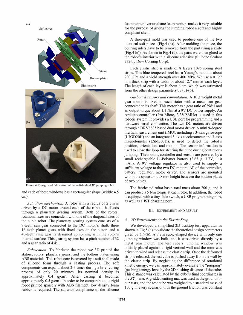
parameters should be taken into account. The approximate model below is a first order approximation for the mechanism design process. As shown in Fig.3, the stator’s cavity has radius R, and the jumping window width w. The elastic strip is fixed to the position C with a length of l. The rotor has radius r and its height to the ground is h (0 < h < l+r). The releasing point J is at an upper corner of the jumping window. The strip length l can be approximately estimated by the sum of the lengths from a straight line segment r′ and a circular segment s which has the same radius as the stator. The distance between J and C is d. At the releasing moment, the rotor has an angle of α with respect to J and C. This angle has a maximum value of αm, due to the stator’s structure limitation as shown by the red dashed line. It can not completely recover to its straight shape
once the strip is rotated above the limit. From the 2D illustration, the following relations can be derived.
s R α= × (1)
r R r′ = − (2)
l s r R R rα′= + = × + − (3)
1 10.5 0.5sin ( ) tan ( )mw w
R hα − −× ×
= + (4)
2 2 1 2(( sin ) ( cos ) )d r R rα α= × + − × (5)
In this jumping mechanism, the rotor’s radius r is determined by the torque requirement and the physical size of the motor’s gearing system. For the stator design, R, h, and w are three key parameters. Once these are determined, the αm, can be calculated by (4).
With a given design of the stator and rotor, the most important design parameter is the elastic strip’s length l . Given the strip’s material and the cross sectional area, the more the strip is bent, the more the elastic energy is stored in the strip. A deformation factor k is defined to scale the stored elastic energy level before jumping.
2( )k l d= − (6)
We can determine the best value of α when k approaches its peak value. The best design for the elastic strip’s length l for a powerful jump can be estimated by α.
C. Design and Fabrication Robot design: Based on this jumping model, we designed
and fabricated a soft body robot that can continuously jump on a surface. As shown in the CAD model (Fig. 4(a)), the robot has a 3D cubic shape with a dimension of 7×7×7 cm. Its body consists of two connected identical halves. The top of each half is made of soft materials. All of the robot’s corners and some part of its surface are elastic. The remaining structural parts of the robot are rigid. The rigidity of the robot’s core provides mechanical strength.
Each half of the robot also plays the role of a stator. The cylinder cavity in each stator has a radius of 3.5 cm and a height of 2 cm. Three identical jumping windows are symmetrically located on each half’s three orthogonal faces
Figure 3. 2D view of the jumping mechanism
Figure 2. Jumping mechanism
1713
and each of these windows has a rectangular shape (width: 4.5 cm).
Actuation mechanism: A rotor with a radius of 2 cm is driven by a DC motor around each of the robot’s half axis through a planetary gearing system. Both of the rotors’ rotational axes are coincident with one of the diagonal axes of the cubic robot. The planetary gearing system consists of a 9-teeth sun gear connected to the DC motor’s shaft, three 16-teeth planet gears with fixed axes on the stator, and a 40-teeth ring gear is designed combining with the rotor’s internal surface. This gearing system has a pitch number of 32 and a gear ratio of 4.4:1.
Fabrication: To fabricate the robot, we 3D printed the stators, rotors, planetary gears, and the bottom plates using ABS materials. This robot core is covered by a soft shell made of silicone foam through a casting process. The soft components can expand about 2-3 times during a brief curing process of only 20 minutes. Its nominal density is approximately 0.4 g/cm3. After casting it becomes approximately 0.5 g/cm3. In order to be comparable to a rigid robot printed sparsely with ABS filament, low density foam rubber is required. The superior compliance of the silicone
foam rubber over urethane foam rubbers makes it very suitable for the purpose of giving the jumping robot a soft and highly compliant shell.
A three-part mold was used to produce one of the two identical soft pieces (Fig.4 (b)). After molding the piece, the pouring inlets have to be removed from the part using a knife (Fig.4 (c)). As shown in Fig.4 (d), the parts were then glued to the robot’s interior with a silicone adhesive (Silicone Sealant 732 by Dow Corning Corp).
Each elastic strip is made of 8 layers 1095 spring steel strips. This blue-tempered steel has a Young’s modulus about 200 GPa and a yield strength over 400 MPa. We use a 0.127 mm thick strip with a width of about 12.7 mm at each layer. The length of each layer is about 6 cm, which was estimated from the other design parameters by (3)-(6).
On-board sensors and computation: A 10 g weight metal gear motor is fixed to each stator with a metal sun gear connected to its shaft. This motor has a gear ratio of 298:1 and an output torque about 1.1 Nm at a 9V DC power supply. An Arduino controller (Pro Micro, 3.3V/8MHz) is used in this robotic system. It provides a USB port for programming and a hardware serial connection. The two DC motors are driven through a DRV8835 based dual motor driver. A mini 9-degree inertial measurement unit (IMU), including a 3-axis gyroscope (L3GD20H) and an integrated 3-axis accelerometer and 3-axis magnetometer (LSM303D), is used to detect the robot’s position, orientation, and motion. The sensor information is used to close the loop for steering the cube during continuous jumping. The motors, controller and sensors are powered by a small rechargeable Li-Polymer battery (2.65 g, 3.7V, 110 mAh). A 9V voltage regulator is also used to supply a sufficient voltage to the two DC motors. All of the controller, battery, regulator, motor driver, and sensors are mounted within the space about 8 mm height between the bottom plates of two halves.
The fabricated robot has a total mass about 200 g, and it can produce a 5 Nm torque at each rotor. In addition, the robot is equipped with a tiny slide switch, a USB programming port, as well as a JST charging port.
III. EXPERIMENT AND RESULT
A. 2D Experiments on the Elastic Strip We developed a simplified 2D desktop test apparatus as
shown in Fig.5 (a) to validate the theoretical design parameters given by (1)-(6). A 7 cm cubic-shaped device with only one jumping window was built, and it was driven directly by a metal gear motor. The test cube’s jumping window was initially placed against a rigid vertical wall and the rotor was driven to wind and release the elastic strip. Once the deformed strip is released, the test cube is pushed away from the wall by the elastic strip. By neglecting the difference of rotational kinetic energy, we can approximately evaluate the “jumping” (pushing) energy level by the 2D pushing distance of the cube. This distance was calculated by the cube’s final coordinates in the XY plane. A gridded cutting mat was used as the ground for our tests, and the test cube was weighed to a standard mass of 150 g in every scenario, thus the ground friction was constant
Stator
Elastic strip
Bottom plate
Soft cover
Rotor
(a)
(b) (c)
(d)
Figure 4. Design and fabrication of the soft-bodied 3D jumping robot
1714
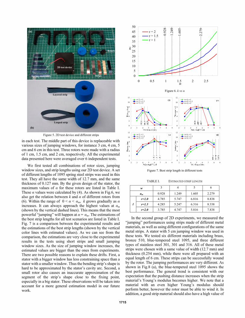
in each test. The middle part of this device is replaceable with various sizes of jumping windows, for instance 3 cm, 4 cm, 5 cm and 6 cm in this test. Three rotors were made with a radius of 1 cm, 1.5 cm, and 2 cm, respectively. All the experimental data presented here were averaged over 6 independent tests.
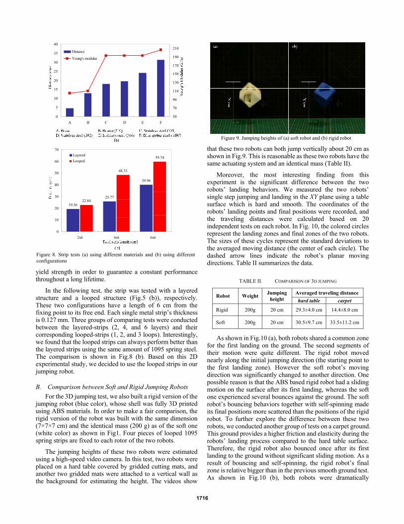
We first tested all combinations of rotor sizes, jumping window sizes, and strip lengths using our 2D test device. A set of different lengths of 1095 spring steel strips was used in this test. They all have the same width of 12.7 mm, and the same thickness of 0.127 mm. By the given design of the stator, the maximum values of α for these rotors are listed in Table I. These α values were calculated by (4). As shown in Fig.6, we also get the relation between k and α of different rotors from (6). Within the range of 0 < α < αm, k grows gradually as α increases. It can always approach the highest values at αm (shown by the vertical dashed lines). This means that the most powerful “jumping” will happen at α = αm. The estimations of the best strip lengths for all test scenarios are listed in Table I. Fig. 7 is a comparison between the experimental results and the estimations of the best strip lengths (shown by the vertical color lines with estimated values). As we can see from the comparison, the estimations are very close to the experimental results in the tests using short strips and small jumping window sizes. As the size of jumping window increases, the estimated values are bigger than the ones from experiments. There are two possible reasons to explain these drifts. First, a stator with a bigger window has less constraining space than a stator with a smaller window. Thus the bending strip’s shape is hard to be approximated by the stator’s cavity arc. Second, a small rotor also causes an inaccurate approximation of the segment of the strip’s shape close to the fixing point, especially in a big stator. These observations will be taken into account for a more general estimation model in our future work.
TABLE I. ESTIMATED STRIP LENGTH
w 3 4 5 6
am 0.928 1.249 1.605 2.279
r=1.0 4.785 5.747 6.816 8.838
r=1.5 4.285 5.247 6.316 8.338 l
r=2.0 3.785 4.747 5.816 7.838 In the second group of 2D experiments, we measured the
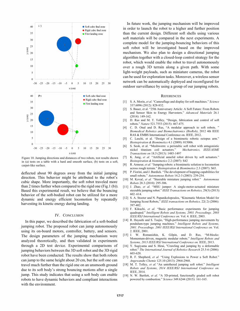
“jumping” performances using strips made of different metal materials, as well as using different configurations of the same metal strips. A stator with 5 cm jumping window was used in these tests. We tested six different materials including brass, bronze 510, blue-tempered steel 1095, and three different types of stainless steel 301, 301 and 316. All of these metal strips were chosen with a same value of width (12.7 mm) and thickness (0.254 mm), while there were all prepared with an equal length of 6 cm. These strips can be successfully wound by the rotor. The jumping performances are very different. As shown in Fig.8 (a), the blue-tempered steel 1095 shows the best performance. The general trend is consistent with our expectation that the pushing distance increases when the strip material’s Young’s modulus becomes higher. We note that a material with an even higher Young’s modulus should perform better, however the rotor must be able to wind it. In addition, a good strip material should also have a high value of
Stators
Rotors
StripsSpring steel(1095)
2D test device
Layered strip
Looped strip
(b)
(a)
Figure 5. 2D test device and different strips
05
101520253035404550
0 0.5 1 1.5 2 2.5
r = 2r = 1.5r = 1
α
k
0.92
8
1.24
9
1.60
5
2.27
9
Figure 6. k vs α
0
2
4
6
8
10
12
2 3 4 5 6 7 8 9
w=3, r=1w=3, r=1.5w=3, r=2
0
2
4
6
8
10
12
2 3 4 5 6 7 8 9
w=4, r=1w=4, r=1.5w=4, r=2
0
2
4
6
8
10
12
2 3 4 5 6 7 8 9
w=5, r=1w=5, r=1.5w=5, r=2
0
2
4
6
8
10
12
2 3 4 5 6 7 8 9
w=6, r=1w=6, r=1.5w=6, r=2
Figure 7. Best strip length in different tests
1715
yield strength in order to guarantee a constant performance throughout a long lifetime.
In the following test, the strip was tested with a layered structure and a looped structure (Fig.5 (b)), respectively. These two configurations have a length of 6 cm from the fixing point to its free end. Each single metal strip’s thickness is 0.127 mm. Three groups of comparing tests were conducted between the layered-strips (2, 4, and 6 layers) and their corresponding looped-strips (1, 2, and 3 loops). Interestingly, we found that the looped strips can always perform better than the layered strips using the same amount of 1095 spring steel. The comparison is shown in Fig.8 (b). Based on this 2D experimental study, we decided to use the looped strips in our jumping robot.
B. Comparison between Soft and Rigid Jumping Robots For the 3D jumping test, we also built a rigid version of the
jumping robot (blue color), whose shell was fully 3D printed using ABS materials. In order to make a fair comparison, the rigid version of the robot was built with the same dimension (7×7×7 cm) and the identical mass (200 g) as of the soft one (white color) as shown in Fig1. Four pieces of looped 1095 spring strips are fixed to each rotor of the two robots.
The jumping heights of these two robots were estimated using a high-speed video camera. In this test, two robots were placed on a hard table covered by gridded cutting mats, and another two gridded mats were attached to a vertical wall as the background for estimating the height. The videos show
that these two robots can both jump vertically about 20 cm as shown in Fig.9. This is reasonable as these two robots have the same actuating system and an identical mass (Table II).
Moreover, the most interesting finding from this experiment is the significant difference between the two robots’ landing behaviors. We measured the two robots’ single step jumping and landing in the XY plane using a table surface which is hard and smooth. The coordinates of the robots’ landing points and final positions were recorded, and the traveling distances were calculated based on 20 independent tests on each robot. In Fig. 10, the colored circles represent the landing zones and final zones of the two robots. The sizes of these cycles represent the standard deviations to the averaged moving distance (the center of each circle). The dashed arrow lines indicate the robot’s planar moving directions. Table II summarizes the data.
TABLE II. COMPARISON OF 3D JUMPING
Averaged traveling distance Robot Weight Jumping height hard table carpet
Rigid 200g 20 cm 29.3±4.0 cm 14.4±8.0 cm
Soft 200g 20 cm 30.5±9.7 cm 33.5±11.2 cm As shown in Fig.10 (a), both robots shared a common zone
for the first landing on the ground. The second segments of their motion were quite different. The rigid robot moved nearly along the initial jumping direction (the starting point to the first landing zone). However the soft robot’s moving direction was significantly changed to another direction. One possible reason is that the ABS based rigid robot had a sliding motion on the surface after its first landing, whereas the soft one experienced several bounces against the ground. The soft robot’s bouncing behaviors together with self-spinning made its final positions more scattered than the positions of the rigid robot. To further explore the difference between these two robots, we conducted another group of tests on a carpet ground. This ground provides a higher friction and elasticity during the robots’ landing process compared to the hard table surface. Therefore, the rigid robot also bounced once after its first landing to the ground without significant sliding motion. As a result of bouncing and self-spinning, the rigid robot’s final zone is relative bigger than in the previous smooth ground test. As shown in Fig.10 (b), both robots were dramatically
0
5
10
15
20
25
30
35
40
A B C D E F50
70
90
110
130
150
170
190
210Distance
Young's modulus
19.36
25.77
39.96
22.84
48.33
59.74
0
10
20
30
40
50
60
70
2x6 4x6 6x6
LayeredLooped
Figure 8. Strip tests (a) using different materials and (b) using different configurations
Figure 9. Jumping heights of (a) soft robot and (b) rigid robot
1716
deflected about 90 degrees away from the initial jumping direction. This behavior might be attributed to the robot’s cubic shape. More importantly, the soft robot traveled more than 2 times further when compared to the rigid one (Fig.1 (b)). Based this experimental result, we believe that the bouncing behavior of the soft-bodied robot can be utilized for a more dynamic and energy efficient locomotion by repeatedly harvesting its kinetic energy during landing.
IV. CONCLUSION In this paper, we described the fabrication of a soft-bodied
jumping robot. The proposed robot can jump autonomously using its on-board motors, controller, battery, and sensors. The design parameters of the jumping mechanism were analyzed theoretically, and then validated in experiments through a 2D test device. Experimental comparisons of jumping behaviors between the 3D soft robot and the 3D rigid robot have been conducted. The results show that both robots can jump to the same height about 20 cm, but the soft one can travel much further than the rigid one on an unsmooth ground due to its soft body’s strong bouncing motions after a single jump. This study indicates that using a soft body can enable robots to have dynamic behaviors and compliant interactions with the environment.
In future work, the jumping mechanism will be improved in order to launch the robot to a higher and further position than the current design. Different soft shells using various soft materials will be compared in the next experiments. A complete model for the jumping-bouncing behaviors of this soft robot will be investigated based on the improved mechanism. We also plan to design a directional jumping algorithm together with a closed-loop control strategy for the robot, which would enable the robot to travel autonomously over a rough 3D terrain along a given path. With some light-weight payloads, such as miniature cameras, the robot can be used for exploration tasks. Moreover, a wireless sensor network can be automatically deployed and reconfigured for outdoor surveillance by using a group of our jumping robots.
REFERENCES [1] S. A. Morin, et al. “Camouflage and display for soft machines.” Science
337.6096 (2012): 828-832. [2] S. Bauer, et al. “25th Anniversary Article: A Soft Future: From Robots
and Sensor Skin to Energy Harvesters.” Advanced Materials 26.1 (2014): 149-162.
[3] D. Rus and M. T. Tolley, “Design, fabrication and control of soft robots.” Nature 521.7553 (2015): 467-475.
[4] C. D. Onal and D. Rus, “A modular approach to soft robots. ” Biomedical Robotics and Biomechatronics (BioRob), 2012 4th IEEE RAS & EMBS International Conference on. IEEE, 2012.
[5] C. Laschi, et al. “Design of a biomimetic robotic octopus arm.” Bioinspiration & Biomimetics 4.1 (2009): 015006.
[6] S. Seok, et al. “Meshworm: a peristaltic soft robot with antagonistic nickel titanium coil actuators.” Mechatronics, IEEE/ASME Transactions on 18.5 (2013): 1485-1497
[7] K. Jung, et al. “Artificial annelid robot driven by soft actuators.” Bioinspiration & biomimetics 2.2 (2007): S42
[8] R. Armour, et al. “Jumping robots: a biomimetic solution to locomotion across rough terrain.” Bioinspiration & Biomimetics 2.3 (2007): S65.
[9] P. Fiorini, and J. Burdick. “The development of hopping capabilities for small robots.” Autonomous Robots 14.2-3 (2003): 239-254.
[10] M. Kovač, et al. “Steerable miniature jumping robot.” Autonomous Robots 28.3 (2010): 295-306.
[11] J. Zhao, et al. “MSU jumper: A single-motor-actuated miniature steerable jumping robot.” IEEE Transactions on Robotics, 29(3) (2013): 602–614.
[12] S. A. Stoeter and N. Papanikolopoulos, “Kinematic Motion Model for Jumping Scout Robots,” IEEE transactions on Robotics, 22( 2) (2006): 397-402.
[13] F. Kikuchi, et al. “Basic performance experiments for jumping quadruped.” Intelligent Robots and Systems, 2003. Proceedings. 2003 IEEE/RSJ International Conference on. Vol. 4. IEEE, 2003.
[14] R. Hayashi and S. Tsujio, “High-performance jumping movements by pendulum-type jumping machines.” Intelligent Robots and Systems, 2001. Proceedings. 2001 IEEE/RSJ International Conference on. Vol. 2. IEEE, 2001.
[15] J. W. Romanishin, K. Gilpin, and D. Rus, “M-blocks: Momentum-driven, magnetic modular robots.” Intelligent Robots and Systems, 2013 IEEE/RSJ International Conference on. IEEE, 2013.
[16] Y. Sugiyama and S. Hirai, "Crawling and jumping by a deformable robot." The International Journal of Robotics Research 25.5-6 (2006): 603-620.
[17] R. F. Shepherd, et al. “Using Explosions to Power a Soft Robot.” Angewandte Chemie 125.10 (2013): 2964-2968.
[18] M. T. Tolley, et al. “An untethered jumping soft robot.” Intelligent Robots and Systems, 2014 IEEE/RSJ International Conference on. IEEE, 2014.
[19] N. W. Bartlett, et al. “A 3D-printed, functionally graded soft robot powered by combustion.” Science 349.6244 (2015): 161-165.
0
5
10
15
20
25
30
35
40
-30 -25 -20 -15 -10 -5 0 5 10 15 20 25 30
x (cm)
y (c
m)
Soft cube final zoneRigid cube final zoneFirst landing zone
0
5
10
15
20
25
30
35
40
-30 -25 -20 -15 -10 -5 0 5 10 15 20 25 30
x (cm)
y (c
m)
Soft cube final zoneRigid cube final zoneFirst landing zone
Figure 10. Jumping directions and distances of two robots, test results shown in (a) tests on a table with a hard and smooth surface, (b) tests on a soft, carpet-like surface.
1717

![Controllable Sliding Bearings and Controllable Lubrication ... · Review Controllable Sliding Bearings and Controllable ... or evolutionary [5], but it does not change the fact that](https://img.pdfslide.us/doc/110x75/5fc50df11ca4e1756528a85b/controllable-sliding-bearings-and-controllable-lubrication-review-controllable.jpg)

![A Soft, Controllable, High Force Density Linear Brake …shape.stanford.edu/research/layerJamming/Layer_Jamming_RAL_2017.… · ... [11], and piezoelectric actuated friction [12]](https://img.pdfslide.us/doc/110x75/5ac5cd3b7f8b9ae06c8df7cb/a-soft-controllable-high-force-density-linear-brake-shape-11-and.jpg)