Embed Size (px)
Citation preview
> REPLACE THIS LINE WITH YOUR PAPER IDENTIFICATION NUMBER (DOUBLE-CLICK HERE TO EDIT) <
1
Abstract—This paper presents a slot antenna array with a
reconfigurable radar cross section (RCS). The antenna system is
formed by combining a liquid absorber with a 2×2 slot antenna
array. The liquid absorber consists of a polymethyl methacrylate
(PMMA) container, a 45% ethanol layer, and a metal ground,
which is attached to the surface of the slot antenna array. The
incident wave can be absorbed by the absorber rather than
reflected in other directions when the PMMA container is filled
with ethanol, which reduces the monostatic and bistatic RCS.
Thus the RCS of the antenna can be changed by injecting and
extracting ethanol while the antenna’s radiation performance in
terms of bandwidth, radiation patterns and gain is well sustained.
In a complex communication system, this can be used to switch
between detection and stealth mode. The mechanism of the
absorber is investigated. The simulated results show that the
antenna with this absorber has monostatic and bistatic RCS
reduction bands from 2.0 GHz to 18.0 GHz, a maximum RCS
reduction of 35 dB with an average RCS reduction of 13.28 dB.
The antenna’s operating band is 100 MHz. Without ethanol, the
antenna has a realized gain of 12.1 dBi, and it drops by 2 dB when
the lossy ethanol is injected. The measured results agree well with
the simulated ones.
Index Terms—Ethanol, reconfigurable, slot antenna array,
radar cross section (RCS).
INTRODUCTION
ADAR cross section (RCS) topics are of fundamental importance in defense electronics, and related antennas
usually contribute to good RCS values for stealth platforms [1]. Different from the RCS reduction of common objects, it is
This work was supported in part by the National Natural Science Foundation
of China under Grant 62071227, in part by the Natural Science Foundation of
Jiangsu Province of China under Grant BK20201289, in part by the Open
Research Program in China’s State Key Laboratory of Millimeter Waves under
Grant K202027 in part by the the Postgraduate Research & Practice Innovation
Program of Jiangsu Province under Grant SJCX20_0070, and in part by the
Natural Sciences and Engineering Research Council (NSERC) of Canada.
Y. Zou, X. Kong, L. Xing, S. Jiang, X. Wang, H. Wang and Y. Zhao are with
the College of Electronic and Information Engineering, Nanjing University of
Aeronautics and Astronautics, Nanjing, 211106, China (e-mail:
Z. Liu is with the School of Information Engineering, Nanchang University,
Nanchang 330031, China.
J. Bornemann is with the Department of Electrical and Computer
Engineering, University of Victoria, Victoria, BC, V8W 2Y2, Canada.
necessary in this scenario to maintain the radiation characteristics of antennas while having low scattering properties.
Recently, several approaches have been proposed to reduce
the RCS of antennas. In these techniques, metasurfaces were
widely used, and metasurfaces with filtering features have been
applied as excellent measures to reduce the RCS. For example,
band-pass frequency selective surfaces (FSSs) as radomes [2],
[3] or a band-notched FSS as a metal ground [4]-[5] were
focused on reducing the out-of-band RCS of antennas. Another
option is to load the antenna with metamaterial absorbers [6], [7].
In this way, the in-band and out-of-band RCS will be reduced
but sometimes the antenna gain is compromised. Furthermore,
chessboard layout matasurfaces were employed to reduce the
antenna RCS through the phase cancellation between incident
and reflected waves [8]-[11]. This method can effectively
reduce the in-band RCS. Moreover, polarization conversion
metasurfaces were used to reduce the RCS of antennas [12]-[16].
This technology can achieve ultra-wideband RCS reduction, but
is only effective for the monostatic RCS. An integrating design
of antennas and low-scattering metasurfaes can achieve
low-RCS systems, while the radiation characteristics are well
maintained [17]-[18]. The combination of Fabry-Perot (FP)
resonator antennas and low-scattering metasurfuces is an
excellent way to deal with gain reduction [19]-[22]. Specifically,
combining a polarization conversion metasurface with a
metamaterial absorber can achieve superior RCS reduction [23].
In this method, the in-band co-polarized waves will be
transformed into their cross-polarized waves and then be
absorbed, while the out-of-band waves will be absorbed
directly.
The low RCS antennas discussed above fall in the category
of passive devices, which are mostly inflexible after fabrication.
Unfortunately, switching and multifunction antennas are
frequently required in practical applications due to changes in a
real environment. Nowadays, some liquid absorbers have been
proposed because of their wide absorption band, transparency,
reconfigurable properties, low-RCS, and low price of the liquid
materials. A liquid material can be used as a radiator in one
design [24]-[25], or it can be used as a unit cell to absorb
incident waves in another one [26]-[28].
To overcome the challenge of RCS reconfigurability, this
paper focuses on a three-layer liquid absorber to reduce the
wideband RCS of a 2×2 slot antenna array. The liquid absorber
can absorb incident waves, thereby reducing the RCS. The
A Slot Antenna Array with Reconfigurable RCS
Using Liquid Absorber Yukun Zou, Xiangkun Kong, Member, IEEE, Lei Xing, Member, IEEE, Shunliu Jiang, Xuemeng Wang,
He Wang, Zhiming Liu, Yongjiu Zhao, Jens Bornemann, Life Fellow, IEEE
R
> REPLACE THIS LINE WITH YOUR PAPER IDENTIFICATION NUMBER (DOUBLE-CLICK HERE TO EDIT) <
2
absorption band of the absorber ranges from 6.1 GHz to 20.54
GHz. The simulated results show that the antenna equipped
with this absorber exhibits monostatic and bistatic RCS
reduction bands from 2.0 GHz to 18.0 GHz, a maximum RCS
reduction of 35 dB with an average RCS reduction of 13.28 dB.
The reconfigurable property of the antenna is performed by
injecting and extracting ethanol in a polymethyl methacrylate
(PMMA) container. The mechanism and functionality of the
liquid absorber is analyzed, and the RCS reconfigurable
performance of the antenna is investigated.
This paper is organized as follows. Section II introduces the
geometry and mechanism of the absorber. Section III presents
the radiation parameters and scattering properties of the
low-RCS slot array antenna with absorber, as well as the design
and construction of the antenna. Section IV concludes the paper.
I. DESIGN OF THE ABSORBER
A. The permittivity of 45% ethanol
The liquid absorber consists of a PMMA container, a 45%
ethanol (55% water) layer, and metal ground. The permittivity
of the 45% ethanol at radio frequency can be represented using
the Debye formula with the filled ethanol temperature of T as
follows [29]:
0 ( ) ( )( , ) ( )
1 ( )
T TT T
i T
(1)
where ε∞(ω,T), ε0(T), τ(T) are the optical permittivity, static
permittivity, and rotational relaxation time, respectively. They
are only related to temperature and can be expressed as
2 3
0 1 1 1 1( )T a bT c T d T (2)
2
0 2( ) ( )b T
T T a e
(3)
2
0
2( )
d
T TT c e
(4)
where a1, a2, b1, b2, c1, c2, d1 and d2 are constant variables of
ε0(T), ε∞(T) and τ(T), respectively. Here we set T = 25°C, so
ε(ω,T) is only related to frequency. First, the permittivity of 45%
ethanol is measured by Dielectric Assessment Kit V 2.4. Then
the above equations are combined with the least square method
to fit the permittivity of the 45% ethanol. The fitting curves are
in good agreement with the measured ones, as shown in Fig. 1.
It can be seen that the imaginary part of the permittivity is large,
which ensures that the liquid absorber has good absorption
property. The fitting curves of the permittivity will be applied to
the full-wave electromagnetic simulation to obtain the features
of the liquid absorber and the antenna array. The parameters are
shown as follows: ε∞(T) = 5.0344, ε0(T) = 735.1702, τ(T) =
20.9273.
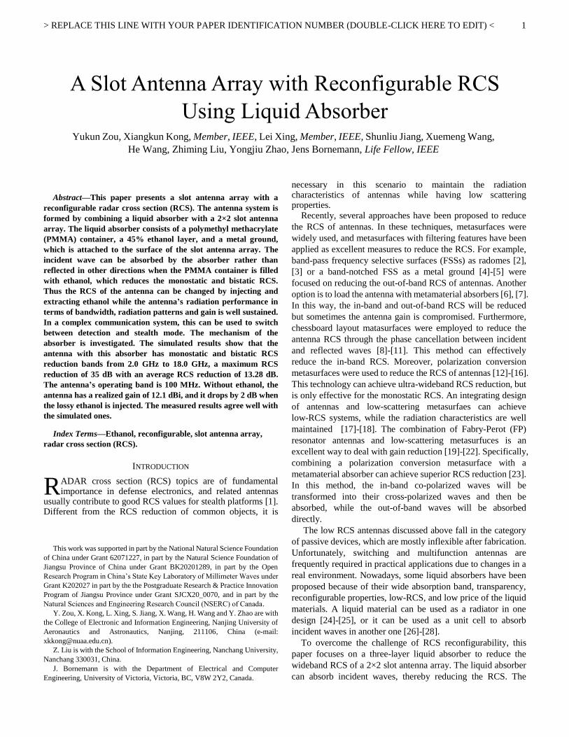
The reason for selecting 45% ethanol instead of all water is
shown in Fig. 2. The real part of the permittivity of ethanol is
substantially lower than that of water, thus enabling the liquid
layer to be designed thicker, which assists us in making full use
of the liquid's fluidity.
Fig. 1 Permittivity of 45% ethanol.
Fig. 2 Comparison of 45% ethanol and water.
B. Structure of the Absorber
(a)
(b)
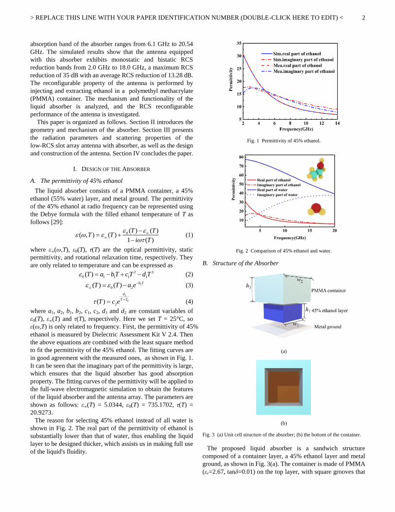
Fig. 3 (a) Unit cell structure of the absorber; (b) the bottom of the container.
The proposed liquid absorber is a sandwich structure
composed of a container layer, a 45% ethanol layer and metal
ground, as shown in Fig. 3(a). The container is made of PMMA
(εr=2.67, tanδ=0.01) on the top layer, with square grooves that

> REPLACE THIS LINE WITH YOUR PAPER IDENTIFICATION NUMBER (DOUBLE-CLICK HERE TO EDIT) <
3
match the shape of the square-type ethanol, as shown in Fig.
3(b). With the metal ground, the container produces an
enclosed chamber that will be filled with ethanol. The length
and width of the PMMA container are w2=13 mm, and its
thickness is h2=9 mm The length and width of the square-type
ethanol layer are w1=5 mm, and its thickness is h1=5 mm.
The S11-parameter of the liquid absorber are investigated using
full-wave electromagnetic simulation, and the results with
different thickness h1 are shown in Fig. 4. The absorption band
(S11 < 10 dB) ranges from 6.1 GHz to 20.54 GHz. The
absorption band is mainly affected by the thickness of the
ethanol layer h1. The absorption band moves to higher
frequencies with the increase of h1 because the resonance length
of the absorber becomes shorter. The absorption band will be
narrow when h1 changes due to the fact that the impedance of
the absorber does not match that of free space in some frequency
bands. Finally, in order to get good absorption property, h1=5
mm is selected.
Fig. 4 Simulation results of the absorber.
C. Mechanism of the Absorber
To better understand the mechanism of the absorber, we use a
one-port network, as proposed in [30], to describe the
impedance and S-parameters of the liquid absorber. For a
parallel resonant circuit, the real part of the impedance is
maximum and the imaginary part is minmum. Therefore, we
can obtain the impedance of the absorber from full-wave
electromagnetic simulation from which we find that there are six
maxima in the real part of the impedance. Thus six parallel
resonant circuits with resonant frequencies f1 to f6, and unloaded
Q factors Q1 to Q6 are shown in Fig. 5. The series inductance and
capacitance are described by XL(f)=XL0 f / fc and XC(f)=XC0 f / fc,
respectively, where fc is the center frequency. In the circuit
model, resonant frequencies, unloaded Q factors and XL0 and XC0
can be found by a genetic algorithm. Thus the impedance of the
equivalent circuit model can be achieved and its S-parameters
can be calculated by Z=(1+|S11|)/(1-|S11|). The parameters are
obtained as follows: Q1=5.28, Q2=4.38, Q3=2.48, Q4=2.52,
Q5=4.22, Q6=4.01, f1=4.28 GHz, f2=4.72 GHz, f3=5.68 GHz,
f4=11.39 GHz, f5=15.5 GHz, f6=20.95 GHz, XL0=141.2 ,
XC0=1.86 . The fitting results are shown in Fig. 6(a) and (b).
The curves of impedance and S-parameters in ADS are slightly
different from those in full-wave electromagnetic simulation
because the number of cascaded parallel resonant circuits is low.
It is worth noting that the use of more cascaded parallel resonant
circuits can achieve more accurate curves of the impedance and
S-parameters.
Fig. 5 Equivalent circuit model of the absorber.
(a)
(b)
Fig. 6 (a) Comparison of impedance between ADS and CST; (b) comparison of
s-parameters between ADS and CST.
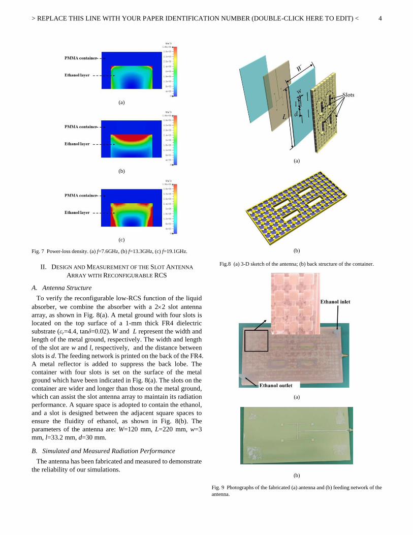
The power-loss density of the absorption minima at 7.6 GHz,
13.3 GHz and 19.1 GHz are presented in Fig. 7 (a), (b) and (c). It
is observed that at 7.6 GHz, the power is mainly concentrated on
the top left and top right of the ethanol layer, the power is
transfered to the upper surface of the ethanol layer at 13.3 GHz;
and the majority of the power is localized at the interface of the
ethanol layer and container layer at 19.1 GHz. This result
reveals that the power is absorbed by the ethanol layer.
> REPLACE THIS LINE WITH YOUR PAPER IDENTIFICATION NUMBER (DOUBLE-CLICK HERE TO EDIT) <
4
(a)
(b)
(c)
Fig. 7 Power-loss density. (a) f=7.6GHz, (b) f=13.3GHz, (c) f=19.1GHz.
II. DESIGN AND MEASUREMENT OF THE SLOT ANTENNA
ARRAY WITH RECONFIGURABLE RCS
A. Antenna Structure
To verify the reconfigurable low-RCS function of the liquid
absorber, we combine the absorber with a 22 slot antenna
array, as shown in Fig. 8(a). A metal ground with four slots is
located on the top surface of a 1-mm thick FR4 dielectric
substrate (εr=4.4, tanδ=0.02). W and L represent the width and
length of the metal ground, respectively. The width and length
of the slot are w and l, respectively, and the distance between
slots is d. The feeding network is printed on the back of the FR4.
A metal reflector is added to suppress the back lobe. The
container with four slots is set on the surface of the metal
ground which have been indicated in Fig. 8(a). The slots on the
container are wider and longer than those on the metal ground,
which can assist the slot antenna array to maintain its radiation
performance. A square space is adopted to contain the ethanol,
and a slot is designed between the adjacent square spaces to
ensure the fluidity of ethanol, as shown in Fig. 8(b). The
parameters of the antenna are: W=120 mm, L=220 mm, w=3
mm, l=33.2 mm, d=30 mm.
B. Simulated and Measured Radiation Performance
The antenna has been fabricated and measured to demonstrate
the reliability of our simulations.
(a)
(b)
Fig.8 (a) 3-D sketch of the antenna; (b) back structure of the container.
(a)
(b)
Fig. 9 Photographs of the fabricated (a) antenna and (b) feeding network of the
antenna.

> REPLACE THIS LINE WITH YOUR PAPER IDENTIFICATION NUMBER (DOUBLE-CLICK HERE TO EDIT) <
5
Fig. 9 (a) and (b) show photographs of the antenna and the
feeding network. A 5245A vector network analyzer was used to
measure the reflection coefficient, and the radiation patterns
were measured in a microwave anechoic chamber, as shown in
Fig. 10.
Fig. 10 The measurement setup of the radiation performance.
Fig. 11 (a) and (b) present the reflection coefficient of the
antenna with ethanol or without ethanol. The 10-dB return-loss
bandwidth of the antenna with or without ethanol is
approximately 100 MHz, ranging from 2.94 GHz to 3.04 GHz.
The difference between simulation and measurement is
attributed to the glass glue used to seal the ethanol, which
slightly changes the impedance of the antenna. The simulated
and measured radiation patterns of the antenna with and
without ethanol at 3 GHz are shown in Fig. 12 (a) and (b). The
3-D radiation patterns of the antenna without and with ethanol
are depicted in Fig. 13 (a) and (b).
(a)
(b)
Fig. 11 Simulated and measured reflection coefficients of the antenna (a)
without ethanol and (b) with ethanol.
The radiation patterns reveal that the radiation performance of
the antenna without or with ethanol remains nearly identical,
which coincides with our initial hypothesis. The realized gain
of the antenna without ethanol is 12.1 dBi at 3 GHz. As the
layer is filled with ethanol, the gain drops by 2 dB due to
ethanol loss. However, considering the good scattering
property of the liquid absorber, this effect is acceptable. The
simulated and measured gain of the antenna without ethanol or
with ethanol are shown in Fig. 14. The glass glue and
background noise are assumed to cause the small difference
between simulation and experiment.
(a)
(b)
Fig. 12 Simulated and measured radiation patterns of the antenna with ethanol
and without ethanol at 3GHz. (a) xoz-plane (b) yoz-plane.
(a) (b)
Fig. 13 3-D radiation patterns of the antenna at 3GHz (a) without ethanol and
(b) with ethanol.
> REPLACE THIS LINE WITH YOUR PAPER IDENTIFICATION NUMBER (DOUBLE-CLICK HERE TO EDIT) <
6
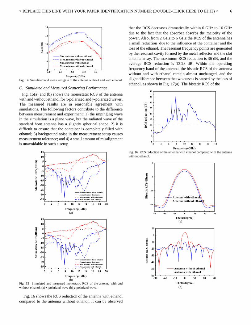
Fig. 14 Simulated and measured gain of the antenna without and with ethanol.
C. Simulated and Measured Scattering Performance
Fig. 15(a) and (b) shows the monostatic RCS of the antenna
with and without ethanol for x-polarized and y-polarized waves.
The measured results are in reasonable agreement with
simulations. The following factors contribute to the difference
between measurement and experiment: 1) the impinging wave
in the simulation is a plane wave, but the radiated wave of the
standard horn antenna has a slightly spherical shape; 2) it is
difficult to ensure that the container is completely filled with
ethanol; 3) background noise in the measurement setup causes
measurement tolerance; and 4) a small amount of misalignment
is unavoidable in such a setup.
(a)
(b)
Fig. 15 Simulated and measured monostatic RCS of the antenna with and
without ethanol. (a) x-polarized wave (b) y-polarized wave.
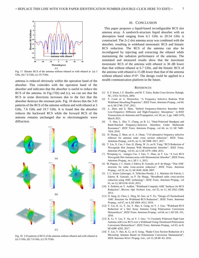
Fig. 16 shows the RCS reduction of the antenna with ethanol
compared to the antenna without ethanol. It can be observed
that the RCS decreases dramatically within 6 GHz to 16 GHz
due to the fact that the absorber absorbs the majority of the
power. Also, from 2 GHz to 6 GHz the RCS of the antenna has
a small reduction due to the influence of the container and the
loss of the ethanol. The resonant frequency points are generated
by the resonant cavity formed by the metal reflector and the slot
antenna array. The maximum RCS reduction is 36 dB, and the
average RCS reduction is 13.28 dB. Within the operating
frequency band of the antenna, the bistatic RCS of the antenna
without and with ethanol remain almost unchanged, and the
slight difference between the two curves is caused by the loss of
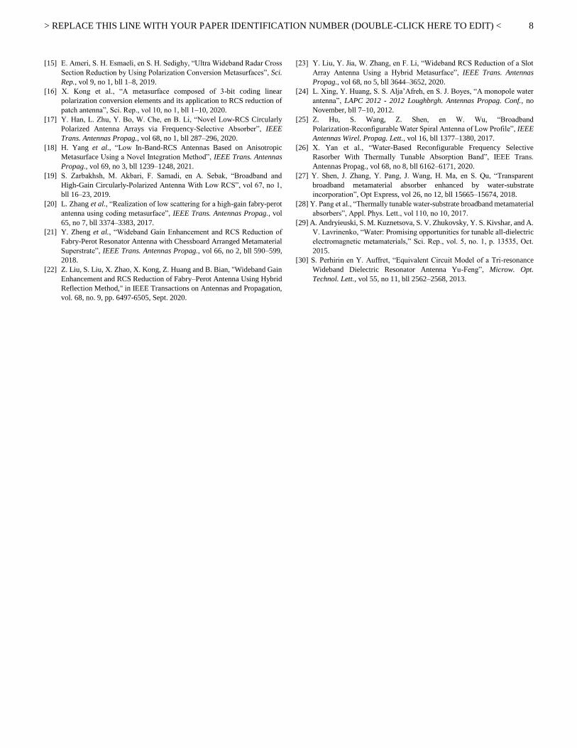
ethanol, as shown in Fig. 17(a). The bistatic RCS of the
Fig. 16 RCS reduction of the antenna with ethanol compared with the antenna
without ethanol.
(a)
(b)
> REPLACE THIS LINE WITH YOUR PAPER IDENTIFICATION NUMBER (DOUBLE-CLICK HERE TO EDIT) <
7
(c)
Fig. 17 Bistatic RCS of the antenna without ethanol or with ethanol at (a) 3
GHz, (b) 7.6 GHz, (c) 19.7GHz.
antenna is reduced obviously within the operation band of the
absorber. This coincides with the operation band of the
absorber and indicates that the absorber is useful to reduce the
RCS of the antenna. In Fig.17(b) and (c), we can see that the
RCS in some directions increases due to the fact that the
absorber destroys the resonant pole. Fig. 18 shows that the 3-D
patterns of the RCS of the antenna without and with ethanol at 3
GHz, 7.6 GHz and 19.7 GHz. It is found that the absorber
reduces the backward RCS while the forward RCS of the
antenna remains unchanged due to electromagnetic wave
diffraction.
(a)
(b)
(c)
Fig. 18 3-D patterns of RCS of the antenna without ethanol and with ethanol at
(a) 3 GHz, (b) 7.6 GHz, (c) 19.7GHz.
III. CONCLUSION
This paper proposes a liquid-based reconfigurable RCS slot
antenna array. A sandwich-structure liquid absorber with an
absorption band ranging from 6.1 GHz to 20.54 GHz is
constructed. The 22 slot antenna array was combined with the
absorber, resulting in wideband monostatic RCS and bistatic
RCS reduction. The RCS of the antenna can also be
reconfigured by injecting and extracting the ethanol while
maintaining the radiation performance of the antenna. The
simulated and measured results show that the maximum
monostatic RCS of the antenna with ethanol is 36 dB lower
than that without ethanol at 6.7 GHz, and the bistatic RCS of
the antenna with ethanol is 15 dB lower than that of the antenna
without ethanol when θ=0°. The design could be applied in a
stealth communication platform in the future.
REFERENCES
[1] E. F. Knott, J. F. Shaeffer, and M. T. Tuley, Radar Cross Section. Raleigh,
NC, USA: SciTech, 2004.
[2] F. Costa en A. Monorchio, “A Frequency Selective Radome With
Wideband Absorbing Properties”, IEEE Trans. Antennas Propag., vol 60,
no 6, bll 2740–2747, 2012.
[3] L. Zhou and Z. Shen, "Hybrid Frequency-Selective Rasorber With
Low-Frequency Diffusion and High-Frequency Absorption," in IEEE
Transactions on Antennas and Propagation, vol. 69, no. 3, pp. 1469-1476,
March 2021.
[4] Y. Han, L. Zhu, Y. Chang, en B. Li, “Dual-Polarized Bandpass and
Band-Notched Frequency-Selective Absorbers Under Multimode
Resonance”, IEEE Trans. Antennas Propag., vol 66, no 12, bll 7449–
7454, 2018.
[5] H. Huang, Z. Shen, en A. A. Omar, “3-D absorptive frequency selective
reflector for antenna radar cross section reduction”, IEEE Trans.
Antennas Propag., vol 65, no 11, bll 5908–5917, 2017.
[6] T. Liu, X. Cao, J. Gao, Q. Zheng, W. Li, en H. Yang, “RCS Reduction of
Waveguide Slot Antenna With Metamaterial Absorber”, IEEE Trans.
Antennas Propag., vol 61, no 3, bll 1479–1484, 2013.
[7] Wenqiang Li, xiangyu Cao, J. Gao, Y. Zhao, en T. Liu, “A Low RCS
Waveguide Slot Antenna array with Metamaterial Absorber”, IEEE Trans.
Antennas Propag., no c, bll 1–1, 2015.
[8] M. Paquay, J. C. Iriarte, I. Ederra, R. Gonzalo, en P. de Maagt, “Thin AMC
structure for radar cross-section reduction”, IEEE Trans. Antennas
Propag., vol 55, no 12, bll 3630–3638, 2007.
[9] J. C. Iriarte Galarregui, A. Tellechea Pereda, J. L. Martínez De Falcón, I.
Ederra, R. Gonzalo, en P. De Maagt, “Broadband radar cross-section
reduction using AMC technology”, IEEE Trans. Antennas Propag., vol
61, no 12, bll 6136–6143, 2013.
[10] S. Perhirin en Y. Auffret, “Wideband Compsite AMC Surfaces for RCS
Reduction”, Microw. Opt. Technol. Lett., vol 55, no 11, bll 2562–2568,
2013.
[11] D. Sang, Q. Chen, L. Ding, M. Guo, en Y. Fu, “Design of Checkerboard
AMC Structure for Wideband RCS Reduction”, IEEE Trans. Antennas
Propag., vol 67, no 4, bll 2604–2612, 2019.
[12] Y. Liu, K. Li, Y. Jia, Y. Hao, S. Gong, en Y. J. Guo, “Wideband RCS
Reduction of a Slot Array Antenna Using Polarization Conversion
Metasurfaces”, IEEE Trans. Antennas Propag., vol 64, no 1, bll 326–331,
2016.
[13] K. Li, Y. Liu, Y. Jia, en Y. J. Guo, “A Circularly Polarized High-Gain
Antenna with Low RCS over a Wideband Using Chessboard Polarization
Conversion Metasurfaces”, IEEE Trans. Antennas Propag., vol 65, no 8,
bll 4288–4292, 2017.
[14] Y. Liu, Y. Hao, K. Li, en S. Gong, “Radar Cross Section Reduction of a
Microstrip Antenna Based on Polarization Conversion Metamaterial”,
IEEE Antennas Wirel. Propag. Lett., vol 15, bll 80–83, 2016.
> REPLACE THIS LINE WITH YOUR PAPER IDENTIFICATION NUMBER (DOUBLE-CLICK HERE TO EDIT) <
8
[15] E. Ameri, S. H. Esmaeli, en S. H. Sedighy, “Ultra Wideband Radar Cross
Section Reduction by Using Polarization Conversion Metasurfaces”, Sci.
Rep., vol 9, no 1, bll 1–8, 2019.
[16] X. Kong et al., “A metasurface composed of 3-bit coding linear
polarization conversion elements and its application to RCS reduction of
patch antenna”, Sci. Rep., vol 10, no 1, bll 1–10, 2020.
[17] Y. Han, L. Zhu, Y. Bo, W. Che, en B. Li, “Novel Low-RCS Circularly
Polarized Antenna Arrays via Frequency-Selective Absorber”, IEEE
Trans. Antennas Propag., vol 68, no 1, bll 287–296, 2020.
[18] H. Yang et al., “Low In-Band-RCS Antennas Based on Anisotropic
Metasurface Using a Novel Integration Method”, IEEE Trans. Antennas
Propag., vol 69, no 3, bll 1239–1248, 2021.
[19] S. Zarbakhsh, M. Akbari, F. Samadi, en A. Sebak, “Broadband and
High-Gain Circularly-Polarized Antenna With Low RCS”, vol 67, no 1,
bll 16–23, 2019.
[20] L. Zhang et al., “Realization of low scattering for a high-gain fabry-perot
antenna using coding metasurface”, IEEE Trans. Antennas Propag., vol
65, no 7, bll 3374–3383, 2017.
[21] Y. Zheng et al., “Wideband Gain Enhancement and RCS Reduction of
Fabry-Perot Resonator Antenna with Chessboard Arranged Metamaterial
Superstrate”, IEEE Trans. Antennas Propag., vol 66, no 2, bll 590–599,
2018.
[22] Z. Liu, S. Liu, X. Zhao, X. Kong, Z. Huang and B. Bian, "Wideband Gain
Enhancement and RCS Reduction of Fabry–Perot Antenna Using Hybrid
Reflection Method," in IEEE Transactions on Antennas and Propagation,
vol. 68, no. 9, pp. 6497-6505, Sept. 2020.
[23] Y. Liu, Y. Jia, W. Zhang, en F. Li, “Wideband RCS Reduction of a Slot
Array Antenna Using a Hybrid Metasurface”, IEEE Trans. Antennas
Propag., vol 68, no 5, bll 3644–3652, 2020.
[24] L. Xing, Y. Huang, S. S. Alja’Afreh, en S. J. Boyes, “A monopole water
antenna”, LAPC 2012 - 2012 Loughbrgh. Antennas Propag. Conf., no
November, bll 7–10, 2012.
[25] Z. Hu, S. Wang, Z. Shen, en W. Wu, “Broadband
Polarization-Reconfigurable Water Spiral Antenna of Low Profile”, IEEE
Antennas Wirel. Propag. Lett., vol 16, bll 1377–1380, 2017.
[26] X. Yan et al., “Water-Based Reconfigurable Frequency Selective
Rasorber With Thermally Tunable Absorption Band”, IEEE Trans.
Antennas Propag., vol 68, no 8, bll 6162–6171, 2020.
[27] Y. Shen, J. Zhang, Y. Pang, J. Wang, H. Ma, en S. Qu, “Transparent
broadband metamaterial absorber enhanced by water-substrate
incorporation”, Opt Express, vol 26, no 12, bll 15665–15674, 2018.
[28] Y. Pang et al., “Thermally tunable water-substrate broadband metamaterial
absorbers”, Appl. Phys. Lett., vol 110, no 10, 2017.
[29] A. Andryieuski, S. M. Kuznetsova, S. V. Zhukovsky, Y. S. Kivshar, and A.
V. Lavrinenko, “Water: Promising opportunities for tunable all-dielectric
electromagnetic metamaterials,” Sci. Rep., vol. 5, no. 1, p. 13535, Oct.
2015.
[30] S. Perhirin en Y. Auffret, “Equivalent Circuit Model of a Tri-resonance
Wideband Dielectric Resonator Antenna Yu-Feng”, Microw. Opt.
Technol. Lett., vol 55, no 11, bll 2562–2568, 2013.
![Reconfigurable Microstrip Double-Dipole Antennas …reconfigurable slot dipole antenna was presented in [10] in the X-band. Patch antenna with polarization diversity using switchable](https://img.pdfslide.us/doc/110x75/5f14df5aad1fda1b4562112a/reconfigurable-microstrip-double-dipole-antennas-reconfigurable-slot-dipole-antenna.jpg)


![Draft Version A Reconfigurable Radiation Pattern Annular Slot Antenna · 2017-02-02 · A Reconfigurable Radiation Pattern Annular Slot Antenna Nur Ab Aziz[1] [2], Alaa H.Radhi[1]](https://img.pdfslide.us/doc/110x75/5eb282f519550100ed25afd5/draft-version-a-reconfigurable-radiation-pattern-annular-slot-antenna-2017-02-02.jpg)


![A Novel Reconfigurable Metal Rim Integrated Open Slot ...livrepository.liverpool.ac.uk/3007816/1/Stanley TAP 2017.pdf[9], [10], loop antennas[11] and active antennas [14]. A smartphone](https://img.pdfslide.us/doc/110x75/5e708969a7fd7a1b852db60a/a-novel-reconfigurable-metal-rim-integrated-open-slot-tap-2017pdf-9-10.jpg)


![[Rcs Iot] Rcs-e v1-2- Joyn](https://img.pdfslide.us/doc/110x75/577cd0231a28ab9e78917fbc/rcs-iot-rcs-e-v1-2-joyn.jpg)