Embed Size (px)
Citation preview

-1-
A Simulation Environment for Excavator Dynamics
Cheol-Gyu Park and Kwang-Ho Lim
Daewoo Heavy Industries & Machinery Ltd.
7-11 Hwasu-dong Dong-gu, Incheon, 401-702, Republic of Korea
Abstract
A dynamic model is essential for dynamics-related studies of an excavator, e.g., controllability, ride
comfort, durability, and so on. Since the hydraulic system, which controls the actuators of an excavator,
has its own dynamics due to compressibility of hydraulic oil, it is required that the dynamics of the
hydraulic system be incorporated into that of the mechanical system to study the coupled dynamic
behavior of the excavator. In this presentation, a simulation environment, which includes both the
hydraulic and mechanical dynamics of an excavator, is explained. MSC.ADAMS and MATLAB/Simulink
are chosen as the implementing tools for the dynamics of the mechanical parts and hydraulic system
respectively, and the coupled dynamic behavior of the excavator is simulated using the co-simulation
method provided by MSC.ADAMS.
1. Introduction
Excavators are used in a wide variety of ways in construction fields, from digging and soil-moving
operations to rock-breaking tasks that require an optional attachment called a breaker. Their common
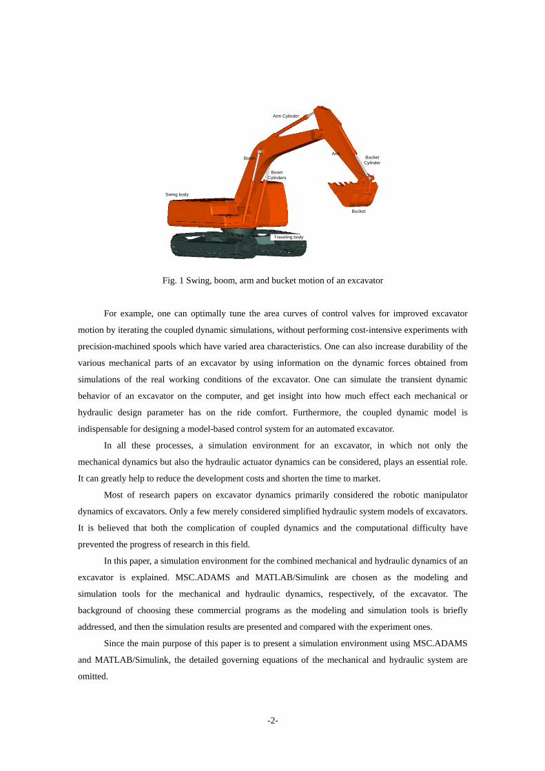
structure consists of a traveling body, a swing body and a front manipulator. The boom, arm and bucket,
as shown in Fig. 1, are three main links comprising the front manipulator of an excavator. Swing, boom,
arm and bucket motions are the most frequent motions of an excavator when it works in a parked
condition. In this paper, the mechanical dynamics refers to the multi-body dynamics of the traveling body,
swing body and front manipulator, as opposed to the hydraulic system dynamics.
Hydraulic actuators such as hydraulic motors and cylinders drive the swing body, boom, arm and
bucket of an excavator. Specifically, a hydraulic motor is used as a driving mechanism for swing motion,
and hydraulic cylinders are used for boom, arm and bucket motion respectively. Since the hydraulic
system has its own dynamics due to compressibility of hydraulic oil and has highly nonlinear
characteristics, it is necessary to consider its effect on the overall dynamic behavior of the excavator.
An exact knowledge of the coupled dynamics is crucial for designing the hydraulic system,
determining the required mechanical strengths of the major parts, improving ride comfort for excavator
operators, and so forth.
-2-
Swing body
Traveling body
BoomArm
Bucket
Boom Cylinders
Arm Cylinder
Bucket Cylinder
Fig. 1 Swing, boom, arm and bucket motion of an excavator
For example, one can optimally tune the area curves of control valves for improved excavator
motion by iterating the coupled dynamic simulations, without performing cost-intensive experiments with
precision-machined spools which have varied area characteristics. One can also increase durability of the
various mechanical parts of an excavator by using information on the dynamic forces obtained from
simulations of the real working conditions of the excavator. One can simulate the transient dynamic
behavior of an excavator on the computer, and get insight into how much effect each mechanical or
hydraulic design parameter has on the ride comfort. Furthermore, the coupled dynamic model is
indispensable for designing a model-based control system for an automated excavator.
In all these processes, a simulation environment for an excavator, in which not only the
mechanical dynamics but also the hydraulic actuator dynamics can be considered, plays an essential role.
It can greatly help to reduce the development costs and shorten the time to market.
Most of research papers on excavator dynamics primarily considered the robotic manipulator
dynamics of excavators. Only a few merely considered simplified hydraulic system models of excavators.
It is believed that both the complication of coupled dynamics and the computational difficulty have
prevented the progress of research in this field.
In this paper, a simulation environment for the combined mechanical and hydraulic dynamics of an
excavator is explained. MSC.ADAMS and MATLAB/Simulink are chosen as the modeling and
simulation tools for the mechanical and hydraulic dynamics, respectively, of the excavator. The
background of choosing these commercial programs as the modeling and simulation tools is briefly
addressed, and then the simulation results are presented and compared with the experiment ones.
Since the main purpose of this paper is to present a simulation environment using MSC.ADAMS
and MATLAB/Simulink, the detailed governing equations of the mechanical and hydraulic system are
omitted.

-3-
2. MSC.ADAMS Mechanical System Model
Considering the various applications of dynamic simulation of an excavator, the software for the
mechanical dynamics of an excavator should be able to give an easy tool for modeling the multi-body
dynamics which includes flexible bodies as well as rigid bodies. Some of the vibration modes of the
structural frames of an excavator need to be considered when the vibrational behaviors are important, for
example, when the dynamic forces at the mounting location of a certain massive object are sought.
MSC.ADAMS provides a few convenient tools for incorporating flexible bodies into a multi-body
dynamic model through ADAMS/Flex plug-in module.
MSC.ADAMS also supplies a variety of tire models in ADAMS/Tire and ADAMS Tracked
Vehicle (ATV) module, which can be used for modeling wheel- and crawler-type excavators. However,
care should be taken using these modules; some parametric data for excavator tires, which are necessary
for advanced tire models, are difficult to obtain, and the tracked excavator modeled in ATV is
computationally inefficient for some purposes.
The ADAMS/Controls plug-in offers various simulation methods for use with MSC.EASY5,
MatrixX, and MATLAB/Simulink. It provides three different simulation methods -continuous, discrete
and control system import- for these dynamics simulation programs. As far as this research work is
concerned, the discrete, i.e., the co-simulation method showed the most acceptable computational
performance for use with MATLAB/Simulink.
Without loss of generality, some assumptions were made to simplify the mechanical system model
of the excavator.
1) Inertial effects of moving parts, e.g., cylinders and pistons, of the hydraulic actuators are
neglected. Masses and mass moments of inertia of the hydraulic actuators are much smaller
than those of the boom, arm and bucket. Therefore, they can be reasonably neglected.
Otherwise, they can be assumed to be constant and included in the masses and mass moments
of inertia of the boom, arm and bucket, if needed.
2) Hydraulic cylinders can transmit axial forces only. There exist no radial force components.
3) Passive revolute joints have no friction. The major sources of friction are the stiction and
viscous friction between the inner wall and the piston in the hydraulic cylinder assembly. These
frictional forces can be treated in the hydraulic system model.
Fig. 2 shows an MSC.ADAMS dynamic model of the excavator for boom motion. The front
manipulator consisting of a boom, an arm and a bucket is treated as a single rigid body. The SFORCE
elements are used to model the axial boom cylinder forces that come from the hydraulic system model.

-4-
Two flexible bodies are used to take the vibrational modes of the traveling and swing body frames into
account. Contact force elements are introduced to model the interaction between the tracks of the
excavator and the ground. The simulation results obtained from this model will be shown in Section 4.
Fig. 2 An example of MSC.ADAMS excavator model
3. Simulink Hydraulic System Model
The hydraulic system of an excavator consists of various components such as pumps, control valves,
auxiliary valves, motors and cylinders. Hydraulic pumps convert the mechanical energy supplied by the
diesel engine to the fluid-power energy stored in hydraulic oil. The main role of control valves is to
control the actuator velocities by properly metering the flows of hydraulic oil into and out of the actuators.
The area characteristics of the control valves are very important since their profiles directly determine the
actuator responses. Auxiliary valves are used to protect the hydraulic circuits and ensure safety during the
excavating motion. A part of the hydraulic circuit diagram of an excavator is shown schematically in Fig.
3
ENGINE
RegulatorRegulator
Pi1 Pi2
Pi1 Pi2
Fig. 3 A part of the hydraulic circuit of an excavator

-5-
Hydraulic motors and cylinders are used as the actuators. They generate torques and forces
necessary for swing, boom, arm and bucket motion. These forces and torques are determined by the
pressures of the chambers in each actuator, and these pressures, in turn, are determined by the velocity
and displacement of the actuator which are calculated from the mechanical dynamics of the excavator.
Therefore, it is in these actuators where the dynamic coupling between the mechanical and hydraulic
system model of the excavator takes place. Fig. 4 shows this relationship schematically.
F : hydraulic cylinder force
xx &, : displacement and velocity of hydraulic cylinder
Fig. 4 Dynamic coupling between the mechanical and hydraulic system of an excavator
The differential equations of a hydraulic system are generally stiff in the numerical point of view.
Moreover, the governing equations of a hydraulic system are mostly strongly nonlinear. Hence, solving
the models of a hydraulic system is numerically challenging.
Hence, two important requirements for software for the hydraulic system of an excavator are to
have stiff ODE solvers suited for the hydraulic system, and to have appropriate interfaces to as many
multi-body dynamics programs as possible.
MATLAB/Simulink is one of the most widely used software tools in control engineers’ society.
Simulink provides relatively easy-to-use modeling tools for dynamic systems on the block diagram basis,
and various numerical ordinary differential equation solvers including the stiff ODE ones.
Fig. 5 shows the performance of each ODE solver in MATLAB. A very simple hydraulic system
model, consisting of a fluid-power source, a chamber and an orifice, was solved using each ODE solver.
The abscissa denotes the given error tolerances and the ordinate denotes the number of steps required
under the given error tolerances. This result shows that the stiff solvers are more efficient than the nonstiff
solvers for error tolerances of 710− or larger, and ODE15S, based on the numerical differentiation
formula, is the fastest method even for more stringent error tolerances.

-6-
Fig. 5 Performance of ODE solvers in MATLAB
Most of dynamics-related programs provide interfaces to MATLAB/Simulink. MSC.ADAMS also
has three different interfaces to Simulink, one of which is the co-simulation method used in this research
work.
In this work, the hydraulic system model of the excavator was implemented in the form of a single
Simulink S-function block. All the governing equations of the model were coded using C language and
the template file provided by MATLAB. The produced MATLAB-executable DLL is called by the S-
function block of the hydraulic system model and greatly shortens the simulation execution time. Fig. 6
shows the typical S-function routines that should be coded to make the S-function block of the hydraulic
system model work properly.
The hydraulic system is modeled using three basic equations: flow equations, continuity equations,
and equations of motion of moving parts such as spools, poppets, etc. A flow equation determines the
flow rate of oil through an orifice.
pACQ d ∆=ρ2
where Q : flow rate through an orifice,
dC : discharge coefficient,
A : opening area of the orifice, ρ : density of hydraulic oil,
p∆ : pressure drop across the orifice.

-7-
Fig. 6 Simulink S-function routines
Continuity equations originate from the mass conservation law and determine the pressure in a
fluid chamber.
outine
QQdtdpV
dtdV
−=+β
where V : chamber volume,
p : chamber pressure,
eβ : effective bulk modulus,
inQ : flow rate into the chamber,
outQ : flow rate out of the chamber.
Fig. 7 shows a modeling example. Fig. 7 (a) shows an auxiliary valve and the important variables
defining the valve model, and (b) depicts the various force components exerted on the poppet of the valve.
The detailed equations for the hydraulic system model are omitted.

-8-
Pinlet
Poutlet
PpilotPpilot_back
QreliefQcheck
Qpiston
Qpilot_backQpilot
(a) An auxiliary valve
Fcheck_friction
Pinlet
Poutlet
xcheck
Fwall
Fcheck_relief
Ppilot
Fcheck_spr
Fcmpr
Frelief_friction
(b) Forces exerted on the poppet
Fig. 7 A model for an auxiliary valve
4. Boom Motion Simulation
As a first step to the simulation of full excavating motion, a mechanical and hydraulic system model for
boom motion was developed.
The mechanical system model for boom motion is the one described at the bottom of Section 2 and
shown in Fig. 2. It contains two flexible bodies to model the traveling and swing body frames. The front
manipulator is modeled as a single rigid body because arm and bucket motions can be ignored during the
boom motion only. It also has two arrays of contact force elements in order to model the interaction
between the tracks of the excavator and the ground.
The hydraulic circuit for boom motion consists of piston pumps, boom control valves, cylinders,
and pipes and hoses connecting the major hydraulic components. Many auxiliary valves are also used to
protect the hydraulic circuit and ensure safe motions. These auxiliary valves include relief valves, check
valves, anti-drift valves, overload protecting valves, and so on.
The static characteristic curves replaced the dynamic model of the pumps and their regulators
because the dynamic model of the pump system of the excavator is very complex. The measured
displacements of spools in the boom control valves were used as the simulation inputs in order to
compare the simulation results with the experiment ones. The dynamic characteristics of other valves and
cylinders were modeled using the equations described in Section 3.
The boom hydraulic system, modeled in this way, consists of more than 60 first order ordinary

-9-
differential equations and is contained in a single Simulink S-function block as described in Section 3.
Fig. 8 shows the Simulink simulation model for MSC.ADAMS co-simulation. Notice the Simulink
S-function block for the hydraulic system dynamics and the ADAMS co-simulation block.
Two different experiments were conducted. The first experiment was performed while moving the
boom slowly in order to use the experiment data for tuning the hydraulic model parameters. The second
one was to move the boom fast and then stop suddenly so as to excite the excavator as much as possible.
The data from this experiment contain information on the overall transient behavior of the excavator.
The simulation results obtained with the tuned model parameters are plotted in Fig. 9. The related
data from the first experiment are also displayed. Fig. 9 (a) and (b) are the plots of pressures associated
with the pump control. Fig. 9 (c) displays the chamber pressures of the boom cylinder. Fig. 9 (d) shows
the boom cylinder velocity and displacement.
The dynamic behavior after the boom stops should be obtained from the co-simulation of
MSC.ADAMS and Simulink, where the dynamic interactions between the boom and the other bodies can
be taken into account.
Fig. 10 plots the co-simulation results and the data from the second experiment. Comparison of the
co-simulation results with the experiment data shows that the simulation results from this simulation
environment have reasonable accuracy and that the simulation technique can be applied to solve the
dynamics-related real world problems such as hydraulic system design, structural design, and ride quality.
ADAMS block
Boom hydraulic system block
Fig. 9 Simulink simulation model for MSC.ADAMS co-simulation

-10-
0.00 0.25 0.50 0.75 1.000.0
0.1
0.2
0.3
0.4
0.5
Nor
mal
ized
Pre
ssur
e
Normalized Time
P1:Exp. P2:Exp. P1:Sim. P2:Sim.
Pump Outlet Pressure
0.00 0.25 0.50 0.75 1.000.00
0.25
0.50
0.75
1.00
Nor
mal
ized
Pre
ssur
e
Normalized Time
Pi1:Exp. Pi2:Exp. Pi1:Sim. Pi2:Sim.
Foot Relief Inlet Pressure
(a) Pump pressure (b) Relief Pressure
0.00 0.25 0.50 0.75 1.000.0
0.1
0.2
0.3
0.4
0.5
Nor
mal
ized
Pre
ssur
e
Normalized Time
Pa:Exp. Pb:Exp. Pa:Sim. Pb:Sim.
Cylinder Chamber Pressure
0.00 0.25 0.50 0.75 1.00-1.0
-0.8
-0.6
-0.4
-0.2
0.0
0.2
0.4
0.6
0.8
1.0
0.80
0.85
0.90
0.95
1.00
Nor
mal
ized
Vel
ocity
Normalized Time
dx/dt:Exp. dx/dt:Sim.
Velocity & Displacement x:Exp. x:Sim.
Nor
mal
ized
Dis
plac
emen
t
(c) Cylinder Pressure (d) Cylinder velocity and displacement
Fig. 9 Simulation results from the tuned hydraulic system model

-11-
(a) Cylinder pressure
(b) Cylinder velocity
Fig. 10 Simulation results from MSC.ADAMS and Simulink co-simulation
5. Conclusions
A simulation environment for excavator dynamics is presented. The mechanical dynamic model of an
excavator is implemented on MSC.ADAMS and the hydraulic system model on Simulink. Comparison of
the co-simulation results with the experiment data shows that the simulation results from this simulation
environment have reasonable accuracy and that the simulation technique can be applied to solve the
dynamics-related real world problems.
The dynamic model of the mechanical and hydraulic system of the excavator is being extended to
simulate simultaneous motion of the swing, boom, arm and bucket, and finally realize the full excavating
motion.

-12-
Reference
(1) Getting Started Using ADAMS/Controls, MSC.Software Corporation, 2003
(2) Writing S-Functions, The MathWorks Inc., 2003
(3) L. Shampine and M. Reichelt, “The MATLAB ODE Suite,” The MathWorks, Inc.
(4) H. E. Merritt, Hydraulic Control Systems, John Wiley & Sons, 1967
(5) P. K. Vähä and M. J. Skibniewski, “Dynamic Model of Excavator,” Journal of Aerospace
Engineering, Vol. 6, No. 2, pp. 148-158, 1993
(6) A. J. Koivo, M. Thomas, E. Kocaoglan, and J. Andrade-Cetto, “Modeling and Control of Excavator
Dynamics during Digging Operation,” J. of Aerospace Engineering, Vol. 9, No. 1, pp. 10-18, 1996
(7) M. Krishna and J. Bares, “Hydraulic System Modeling through Memory-based Learning,” IEEE
Intelligent Robot Systems Conference, 1998