Embed Size (px)
Citation preview
Methods Note/
A Simple Method to Hide Data Loggers Safelyin Observation Wellsby Gunnar Lorenzen1, Christoph Sprenger2, and Asaf Pekdeger2
AbstractSubmersible data loggers are widely used for groundwater monitoring, but their application often runs the
risk of hardware and data loss through vandalism or theft. During a field study in India, the authors of this articleexperienced that well locks attract the attention of unauthorized persons and do not provide secure protection inunattended areas. To minimize the risk of losing data loggers, a cheap and simple solution has been inventedto hide the instruments and associated attachments below the ground surface, inside observation wells. It relieson attaching the logger to a length of small-diameter pipe that is submerged at the bottom of the well, insteadof attaching it to the top of the well. The small-diameter pipe with the logger is connected to a small bottlecontaining a magnet that floats on the water surface of the well and can be recovered using another bottle alsowith a magnet. A logger that is concealed in this way is difficult to detect and access without knowledge ofthe method and adequate removal tools. The system was tested and successfully applied for monitoring shallowobservation wells at three field sites in Greater Delhi, India.
IntroductionWater level loggers have become standard tools for
groundwater monitoring and allow continuous measur-ing and recording of the hydraulic heads in observationwells. They provide crucial information for a numberof applications, such as the observation of drawdownduring pumping tests or long-term monitoring for waterresources management. Modern devices are fully sub-mersible and combine battery, pressure transducer, datalogger, and communications interface in a handy robustdesign. Atmospheric pressure data loggers can be usedto account for barometric effects as described by Ras-mussen and Crawford (1997). Temperature probes areoften included to perform automatic compensation of pres-sure measurements. The temperature data can also be used
1Corresponding author: Hydrogeology Group, Institute ofGeological Sciences, Freie Universitat Berlin, Malteserstr. 74-100,Berlin 12249, Germany; [email protected]
2Hydrogeology Group, Institute of Geological Sciences, FreieUniversitat Berlin, Malteserstr. 74-100, Berlin 12249, Germany.
Received April 2010, accepted October 2010.Copyright © 2010 The Author(s)Journal compilation © 2010 National Ground Water Association.doi: 10.1111/j.1745-6584.2010.00771.x
for detecting heat as a groundwater tracer in a wide vari-ety of hydrogeological settings (Stonestrom and Constantz2003; Anderson 2005).
In spite of the usefulness of stand-alone monitoringdevices, their field application runs the risk of the high-tech components being displaced or damaged. Potentialtheft or vandalism has to be considered at most field sites,and researchers may lose not only the hardware but alsovaluable data. Fully submersible devices are not them-selves visible, but they are usually attached to the top ofthe well (well collar) with a steel cable, which may attractthe attention of curious passers-by. It is therefore oftenrecommended to take protective measures and invest infences, guards, or well-locking systems or to finish wellsat grade to make them less visible. However, such mea-sures are not only expensive and time consuming to installbut may even attract unwanted attention. Especially inunattended areas, locks do not guarantee security becausethey can be broken open with relatively simple tools.
The Delhi ExperienceThe idea to hide data loggers in observation wells
arose during a research project that was carried out in
450 Vol. 49, No. 3–GROUND WATER–May-June 2011 (pages 450–453) NGWA.org
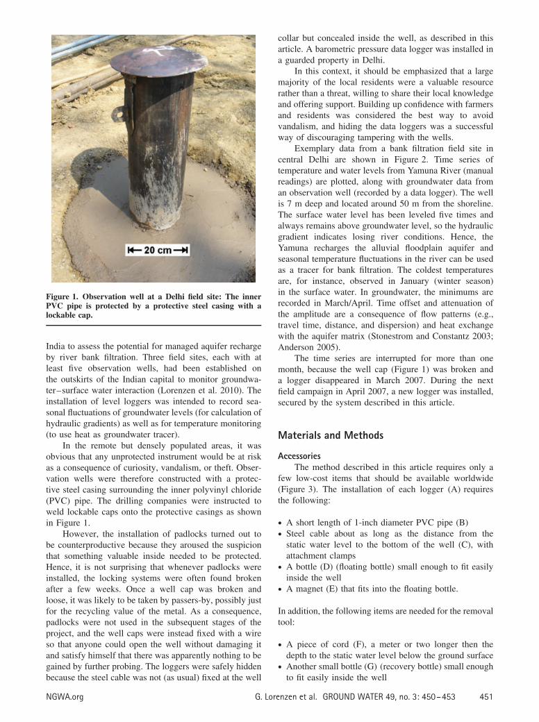
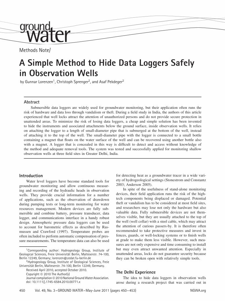
Figure 1. Observation well at a Delhi field site: The innerPVC pipe is protected by a protective steel casing with alockable cap.
India to assess the potential for managed aquifer rechargeby river bank filtration. Three field sites, each with atleast five observation wells, had been established onthe outskirts of the Indian capital to monitor groundwa-ter–surface water interaction (Lorenzen et al. 2010). Theinstallation of level loggers was intended to record sea-sonal fluctuations of groundwater levels (for calculation ofhydraulic gradients) as well as for temperature monitoring(to use heat as groundwater tracer).
In the remote but densely populated areas, it wasobvious that any unprotected instrument would be at riskas a consequence of curiosity, vandalism, or theft. Obser-vation wells were therefore constructed with a protec-tive steel casing surrounding the inner polyvinyl chloride(PVC) pipe. The drilling companies were instructed toweld lockable caps onto the protective casings as shownin Figure 1.
However, the installation of padlocks turned out tobe counterproductive because they aroused the suspicionthat something valuable inside needed to be protected.Hence, it is not surprising that whenever padlocks wereinstalled, the locking systems were often found brokenafter a few weeks. Once a well cap was broken andloose, it was likely to be taken by passers-by, possibly justfor the recycling value of the metal. As a consequence,padlocks were not used in the subsequent stages of theproject, and the well caps were instead fixed with a wireso that anyone could open the well without damaging itand satisfy himself that there was apparently nothing to begained by further probing. The loggers were safely hiddenbecause the steel cable was not (as usual) fixed at the well
collar but concealed inside the well, as described in thisarticle. A barometric pressure data logger was installed ina guarded property in Delhi.
In this context, it should be emphasized that a largemajority of the local residents were a valuable resourcerather than a threat, willing to share their local knowledgeand offering support. Building up confidence with farmersand residents was considered the best way to avoidvandalism, and hiding the data loggers was a successfulway of discouraging tampering with the wells.
Exemplary data from a bank filtration field site incentral Delhi are shown in Figure 2. Time series oftemperature and water levels from Yamuna River (manualreadings) are plotted, along with groundwater data froman observation well (recorded by a data logger). The wellis 7 m deep and located around 50 m from the shoreline.The surface water level has been leveled five times andalways remains above groundwater level, so the hydraulicgradient indicates losing river conditions. Hence, theYamuna recharges the alluvial floodplain aquifer andseasonal temperature fluctuations in the river can be usedas a tracer for bank filtration. The coldest temperaturesare, for instance, observed in January (winter season)in the surface water. In groundwater, the minimums arerecorded in March/April. Time offset and attenuation ofthe amplitude are a consequence of flow patterns (e.g.,travel time, distance, and dispersion) and heat exchangewith the aquifer matrix (Stonestrom and Constantz 2003;Anderson 2005).
The time series are interrupted for more than onemonth, because the well cap (Figure 1) was broken anda logger disappeared in March 2007. During the nextfield campaign in April 2007, a new logger was installed,secured by the system described in this article.
Materials and Methods
AccessoriesThe method described in this article requires only a
few low-cost items that should be available worldwide(Figure 3). The installation of each logger (A) requiresthe following:
• A short length of 1-inch diameter PVC pipe (B)• Steel cable about as long as the distance from the
static water level to the bottom of the well (C), withattachment clamps
• A bottle (D) (floating bottle) small enough to fit easilyinside the well
• A magnet (E) that fits into the floating bottle.
In addition, the following items are needed for the removaltool:
• A piece of cord (F), a meter or two longer then thedepth to the static water level below the ground surface
• Another small bottle (G) (recovery bottle) small enoughto fit easily inside the well
NGWA.org G. Lorenzen et al. GROUND WATER 49, no. 3: 450–453 451
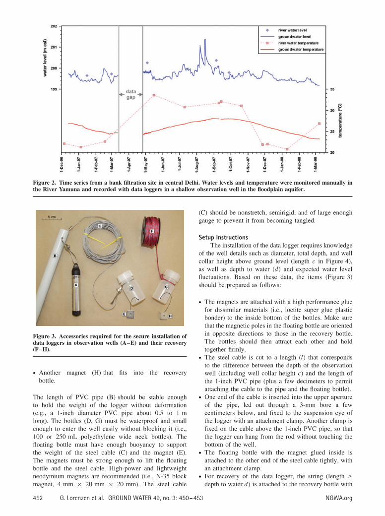
Figure 2. Time series from a bank filtration site in central Delhi. Water levels and temperature were monitored manually inthe River Yamuna and recorded with data loggers in a shallow observation well in the floodplain aquifer.
Figure 3. Accessories required for the secure installation ofdata loggers in observation wells (A–E) and their recovery(F–H).
• Another magnet (H) that fits into the recoverybottle.
The length of PVC pipe (B) should be stable enoughto hold the weight of the logger without deformation(e.g., a 1-inch diameter PVC pipe about 0.5 to 1 mlong). The bottles (D, G) must be waterproof and smallenough to enter the well easily without blocking it (i.e.,100 or 250 mL polyethylene wide neck bottles). Thefloating bottle must have enough buoyancy to supportthe weight of the steel cable (C) and the magnet (E).The magnets must be strong enough to lift the floatingbottle and the steel cable. High-power and lightweightneodymium magnets are recommended (i.e., N-35 blockmagnet, 4 mm × 20 mm × 20 mm). The steel cable
(C) should be nonstretch, semirigid, and of large enoughgauge to prevent it from becoming tangled.
Setup InstructionsThe installation of the data logger requires knowledge
of the well details such as diameter, total depth, and wellcollar height above ground level (length c in Figure 4),as well as depth to water (d) and expected water levelfluctuations. Based on these data, the items (Figure 3)should be prepared as follows:
• The magnets are attached with a high performance gluefor dissimilar materials (i.e., loctite super glue plasticbonder) to the inside bottom of the bottles. Make surethat the magnetic poles in the floating bottle are orientedin opposite directions to those in the recovery bottle.The bottles should then attract each other and holdtogether firmly.
• The steel cable is cut to a length (l) that correspondsto the difference between the depth of the observationwell (including well collar height c) and the length ofthe 1-inch PVC pipe (plus a few decimeters to permitattaching the cable to the pipe and the floating bottle).
• One end of the cable is inserted into the upper apertureof the pipe, led out through a 3-mm bore a fewcentimeters below, and fixed to the suspension eye ofthe logger with an attachment clamp. Another clamp isfixed on the cable above the 1-inch PVC pipe, so thatthe logger can hang from the rod without touching thebottom of the well.
• The floating bottle with the magnet glued inside isattached to the other end of the steel cable tightly, withan attachment clamp.
• For recovery of the data logger, the string (length ≥depth to water d) is attached to the recovery bottle with
452 G. Lorenzen et al. GROUND WATER 49, no. 3: 450–453 NGWA.org
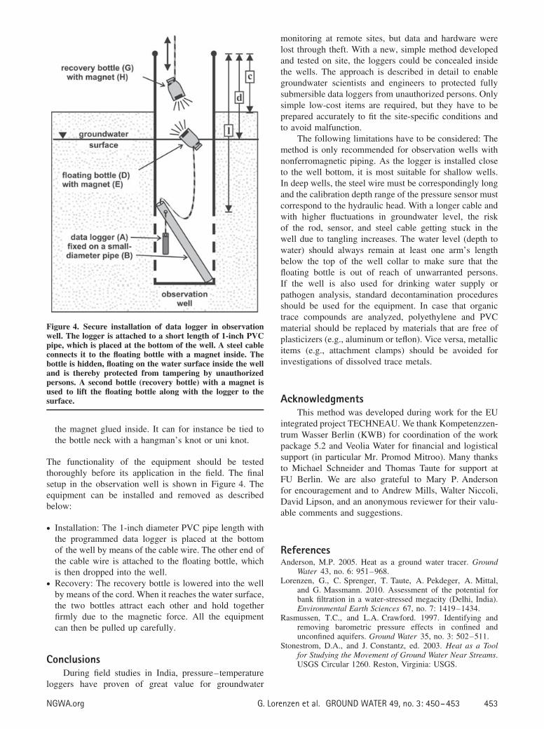
Figure 4. Secure installation of data logger in observationwell. The logger is attached to a short length of 1-inch PVCpipe, which is placed at the bottom of the well. A steel cableconnects it to the floating bottle with a magnet inside. Thebottle is hidden, floating on the water surface inside the welland is thereby protected from tampering by unauthorizedpersons. A second bottle (recovery bottle) with a magnet isused to lift the floating bottle along with the logger to thesurface.
the magnet glued inside. It can for instance be tied tothe bottle neck with a hangman’s knot or uni knot.
The functionality of the equipment should be testedthoroughly before its application in the field. The finalsetup in the observation well is shown in Figure 4. Theequipment can be installed and removed as describedbelow:
• Installation: The 1-inch diameter PVC pipe length withthe programmed data logger is placed at the bottomof the well by means of the cable wire. The other end ofthe cable wire is attached to the floating bottle, whichis then dropped into the well.
• Recovery: The recovery bottle is lowered into the wellby means of the cord. When it reaches the water surface,the two bottles attract each other and hold togetherfirmly due to the magnetic force. All the equipmentcan then be pulled up carefully.
ConclusionsDuring field studies in India, pressure–temperature
loggers have proven of great value for groundwater
monitoring at remote sites, but data and hardware werelost through theft. With a new, simple method developedand tested on site, the loggers could be concealed insidethe wells. The approach is described in detail to enablegroundwater scientists and engineers to protected fullysubmersible data loggers from unauthorized persons. Onlysimple low-cost items are required, but they have to beprepared accurately to fit the site-specific conditions andto avoid malfunction.
The following limitations have to be considered: Themethod is only recommended for observation wells withnonferromagnetic piping. As the logger is installed closeto the well bottom, it is most suitable for shallow wells.In deep wells, the steel wire must be correspondingly longand the calibration depth range of the pressure sensor mustcorrespond to the hydraulic head. With a longer cable andwith higher fluctuations in groundwater level, the riskof the rod, sensor, and steel cable getting stuck in thewell due to tangling increases. The water level (depth towater) should always remain at least one arm’s lengthbelow the top of the well collar to make sure that thefloating bottle is out of reach of unwarranted persons.If the well is also used for drinking water supply orpathogen analysis, standard decontamination proceduresshould be used for the equipment. In case that organictrace compounds are analyzed, polyethylene and PVCmaterial should be replaced by materials that are free ofplasticizers (e.g., aluminum or teflon). Vice versa, metallicitems (e.g., attachment clamps) should be avoided forinvestigations of dissolved trace metals.
AcknowledgmentsThis method was developed during work for the EU
integrated project TECHNEAU. We thank Kompetenzzen-trum Wasser Berlin (KWB) for coordination of the workpackage 5.2 and Veolia Water for financial and logisticalsupport (in particular Mr. Promod Mitroo). Many thanksto Michael Schneider and Thomas Taute for support atFU Berlin. We are also grateful to Mary P. Andersonfor encouragement and to Andrew Mills, Walter Niccoli,David Lipson, and an anonymous reviewer for their valu-able comments and suggestions.
ReferencesAnderson, M.P. 2005. Heat as a ground water tracer. Ground
Water 43, no. 6: 951–968.Lorenzen, G., C. Sprenger, T. Taute, A. Pekdeger, A. Mittal,
and G. Massmann. 2010. Assessment of the potential forbank filtration in a water-stressed megacity (Delhi, India).Environmental Earth Sciences 67, no. 7: 1419–1434.
Rasmussen, T.C., and L.A. Crawford. 1997. Identifying andremoving barometric pressure effects in confined andunconfined aquifers. Ground Water 35, no. 3: 502–511.
Stonestrom, D.A., and J. Constantz, ed. 2003. Heat as a Toolfor Studying the Movement of Ground Water Near Streams.USGS Circular 1260. Reston, Virginia: USGS.
NGWA.org G. Lorenzen et al. GROUND WATER 49, no. 3: 450–453 453