Embed Size (px)
Citation preview
8/3/2019 A Simple Inverter for Florescent Lamps
http://slidepdf.com/reader/full/a-simple-inverter-for-florescent-lamps 1/2
A simple inverter for florescent lamps
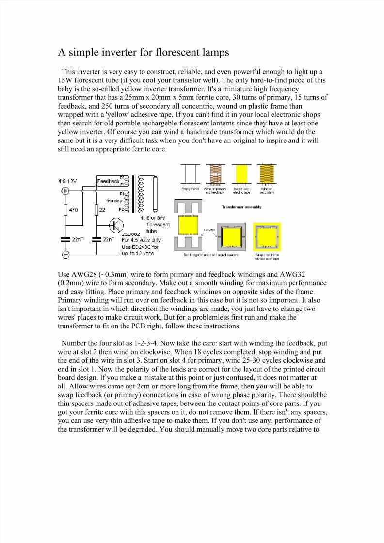
This inverter is very easy to construct, reliable, and even powerful enough to light up a
15W florescent tube (if you cool your transistor well). The only hard-to-find piece of this baby is the so-called yellow inverter transformer. It's a miniature high frequency
transformer that has a 25mm x 20mm x 5mm ferrite core, 30 turns of primary, 15 turns of feedback, and 250 turns of secondary all concentric, wound on plastic frame thanwrapped with a 'yellow' adhesive tape. If you can't find it in your local electronic shops
then search for old portable rechargeble florescent lanterns since they have at least one
yellow inverter. Of course you can wind a handmade transformer which would do the
same but it is a very difficult task when you don't have an original to inspire and it willstill need an appropriate ferrite core.
Use AWG28 (~0.3mm) wire to form primary and feedback windings and AWG32
(0.2mm) wire to form secondary. Make out a smooth winding for maximum performanceand easy fitting. Place primary and feedback windings on opposite sides of the frame.
Primary winding will run over on feedback in this case but it is not so important. It alsoisn't important in which direction the windings are made, you just have to change two
wires' places to make circuit work, But for a problemless first run and make the
transformer to fit on the PCB right, follow these instructions:
Number the four slot as 1-2-3-4. Now take the care: start with winding the feedback, putwire at slot 2 then wind on clockwise. When 18 cycles completed, stop winding and put
the end of the wire in slot 3. Start on slot 4 for primary, wind 25-30 cycles clockwise and
end in slot 1. Now the polarity of the leads are correct for the layout of the printed circuit
board design. If you make a mistake at this point or just confused, it does not matter atall. Allow wires came out 2cm or more long from the frame, then you will be able to
swap feedback (or primary) connections in case of wrong phase polarity. There should be
thin spacers made out of adhesive tapes, between the contact points of core parts. If yougot your ferrite core with this spacers on it, do not remove them. If there isn't any spacers,
you can use very thin adhesive tape to make them. If you don't use any, performance of
the transformer will be degraded. You should manually move two core parts relative to

8/3/2019 A Simple Inverter for Florescent Lamps
http://slidepdf.com/reader/full/a-simple-inverter-for-florescent-lamps 2/2
each other in order to find the best operating point which can be determined from the
brightness of the lamp.