Embed Size (px)
Citation preview

What is Stormwater Runoff?
Stormwater runoff describes the flow of rainwater or meltwater from
snow or ice over the land’s surface.
On undisturbed sites, much of the
stormwater is intercepted by natu-
ral ground cover or is absorbed
into the ground. Land clearing and
development reduces the capacity
of the land to absorb rainwater and
snowmelt, which leads to more wa-
ter flowing over the land and into
surface waters.
As water flows over the land, it
picks up exposed soil as well as
any chemicals, fertilizers or pollutants that are present. Stormwater car-
ries these polluting substances over impervious surfaces and through
storm drains and drainage ditches. Impervious surfaces are surfaces that
cannot effectively absorb and infiltrate water. Examples of impervious
surfaces include, but are not limited to, roofs, decks, patios and paved,
gravel or crushed stone driveways, parking areas and walkways unless
designed to effectively absorb and infiltrate water. This flow of stormwa-
ter eventually reaches a body of water, where the sediments, nutrients
and pollutants are deposited.
IntroductionThe recently revised Com-
prehensive Shoreland Protec-
tion Act (CSPA), which was
enacted to help protect the
state’s surface waters, in-
cludes limits on development
that contribute to stormwater
runoff. If you are a shoreland
homeowner, your property
may produce stormwater run-
off that directly impacts the
quality of our public waters.
However, you can reduce or
prevent polluted stormwater
runoff. This guide provides
several simple and cost effec-
tive practices that shoreland
homeowners can install to
address stormwater runoff
from roofs, patios, lawns and
driveways. These practices
can be used to meet the
provisions of the CSPA. The
guide also includes general
information about what state
environmental permits, if
any, are necessary for incor-
porating these practices.
Polluted stormwater runoff flow-ing into a storm drain.
A Shoreland Homeowner’s Guide
to Stormwater Management~ protecting your home & environment ~
NH Department of Environmental Services29 Hazen Drive, Concord, NH 03301 • 603.271.3503 • www.des.nh.gov
10 in One!
Please note that this document is actually 10 articles in one: an introductory document and nine guidance sheets, which may be printed out altogether or separately. They are:
Introductory Document, 4 pg.Dripline Trench, 1 pg.Drywells, 1 pg.Infiltration Steps - New, 2 pg.Infiltration Steps - Retrofit, 1 pg.
Infiltration Trench, 1 pg. Paths & Walkways, 1 pg.Rain Barrels, 1 pg.Rain Gardens, 1 pg.Water Bars, 2 pg.

How Does Stormwater Runoff Affect Surface Waters?
As stormwater flows overland as runoff, it picks up and carries a
load of sediment, nutrients and pollutants. The faster and more
concentrated the flow, the greater the load that stormwater run-
off can carry.
Stormwater runoff from developed areas may carry pollutants
such as exposed soil, sediment and organic matter; chemicals,
fertilizers and herbicides from lawns; animal wastes, cigarette
butts and other litter; road salt, chemicals and oil from paved
surfaces; and grass clippings, leaves and other yard waste.
Stormwater carries these substances through pipes, drains and
ditches and eventually into lakes, ponds, rivers and streams.
Stormwater slows down after entering a waterbody and deposits
the load of nutrients, bacteria, toxic substances, sediment, and
other pollutants into the surface water.
Stormwater runoff can cause water quality declines in the follow-
ing ways:
1. NUTRIENTS: Runoff from fertilized lawns, landscaped yards
and agricultural fields into waterbodies contributes large quanti-
ties of nutrients to waterbodies. Sewer systems as well as pet
and wildlife waste can also contribute excess nutrients. These
nutrients accelerate algal and cyanobacteria blooms and fuel the
increased growth of aquatic plants, which promotes declines in
water clarity and dissolved oxygen which can impact aquatic spe-
cies and cold water fisheries in particular.
2. BACTERIA: Bacteria from human and animal waste can con-
taminate surface waters and lead to beach closures, shellfish bed
closures and other measures to protect public health.
3. TOXIC SUBSTANCES: Industrial and agricultural pollutants,
including ammonia, metals, organic compounds, pesticides, ni-
trates and salts, can harm wildlife and also pose a contamination
threat for groundwater and public drinking water supplies.
4. SEDIMENT: Heavy loads of eroded sediment deposited into
waterbodies can smother aquatic habitat, decrease water clarity,
increase water temperature and cause the depletion of dissolved
oxygen in the water column.
Protecting Water Quality through the Comprehensive Shoreland Protection Act
The Comprehensive Shoreland Protection Act (CSPA), RSA 483-
B, was enacted to protect the water quality of New Hampshire’s
surface waters by managing the disturbance of shoreland areas.
Alteration of Terrain Permits
The Alteration of Terrain (AoT) per-
mit protects New Hampshire surface
waters, drinking water supplies, and
groundwater by controlling soil ero-
sion and managing stormwater runoff
from developed areas. This permit-
ting program applies to earth mov-
ing operations, such as industrial,
commercial, and residential develop-
ments as well as sand pits, gravel
pits, and rock quarries.
Permits are issued by DES after a
technical review of the application,
which includes the project plans
and supporting documents. An AoT
permit is required whenever a proj-
ect proposes to disturb more than
100,000 square feet of contiguous
terrain (50,000 square feet, if any
portion of the project is within the
Protected Shoreland) or disturbs an
area having a grade of 25 percent or
greater within 50 feet of any surface
water. In addition to these larger
disturbances, the AoT General Permit
by Rule applies to smaller sites.
To determine if an AoT permit
may be necessary for the work that
you plan to conduct, contact the
AoT Program at (603) 271-3434. For
more information, please click on the
program’s name in the “A to Z List” at
www.des.nh.gov.
Funding provided by the American Recouvery and Reinvestment Act under Section 604(b) of the Clean Water Act. Guidance sheets used with permission from the Maine Department of Environmental Protection.
NHDES-WD-10-8

To reduce the transport of nutrients, sediments and other pollut-
ants into the State’s surface waters, the CSPA seeks to maintain
a shoreland buffer of natural vegetation to protect against the
potentially harmful effects of stormwater runoff.
The CSPA applies to all fourth order and greater streams, desig-
nated rivers, tidal waters and lakes, ponds and impoundments
over 10 acres in size. DES maintains an inventory of these water-
bodies in the Consolidated List of Water Bodies subject to RSA
483-B, which may be found at http://des.nh.gov/organization/
divisions/water/wetlands/cspa/water_bodies.htm.
Around these waterbodies, the CSPA applies to development and land
use activities within 250 feet of the water’s edge or high water mark,
called the reference line. This area is referred to as the “Protected
Shoreland.” Within the Protected Shoreland, the CSPA requires:
A waterfront buffer with minimal disturbance to natural veg-•
etation and natural groundcover within 50 feet of the Refer-
ence Line.
A natural woodland buffer retaining a certain percentage of •
vegetation in an unaltered state between 50 and 150 feet of
the Reference Line.
Limitations on impervious surfaces, lot subdivision, excava-•
tion and filling within 250 feet of the Reference Line.
According to the CSPA, lots within the Protected Shoreland may
not have greater than 30 percent impervious surface coverage.
If a project within the Protected Shoreland proposes an impervi-
ous surface coverage of more than 20 percent, then a stormwater
management system must be implemented and maintained to
Wetlands Permits
If you plan to conduct work in the
state’s surface waters or in the bank
of a lake, pond or river, you need
to secure a Wetlands Permit prior to
starting the activity. The bank is the
transitional slope immediately adja-
cent to the edge of a surface water
body, the upper limit of which is
usually defined by a break in slope.
RSA 482-A authorizes DES to pro-
tect wetlands and surface waters by
requiring a permit for dredge, fill or
construction in wetlands and water-
bodies. A Wetlands Permit is required
for any alteration of tidal or non-tidal
wetlands. Permits are issued by the
Wetlands Bureau after a technical re-
view of the application and confirma-
tion that the proposed activities meet
the statutory requirements. The appli-
cant must demonstrate that potential
impacts have been avoided to the
maximum extent practicable and that
any unavoidable impacts have been
minimized. Impacts that are specifi-
cally covered by a Wetlands Permit or
a Wetlands Permit by Notification will
not need a Shoreland Permit.
Most of the small-scale stormwater
management structures included in
this guide would be installed above
the top of the bank; however, if you
plan to install infiltration steps or a
path or walkway, these structures
may be installed in the bank.
To determine if your plan requires
a Wetlands Permit, contact the Wet-
lands Program at (603) 271-2147, or
click on the program’s name in the “A
to Z List” at www.des.nh.gov.

effectively absorb and infiltrate the post-construction stormwater
that would occur as a result of the new impervious surfaces. A
“stormwater management system” includes stormwater treatment
prcatices, stormwater conveyences and groundwater recharge
practices.
When to Use Stormwater Management Practices
If you plan to expand existing structures, construct new struc-
tures or develop a previously undeveloped lot within the Protect-
ed Shoreland, employing the stormwater management practices
included in this guide may be an effective means of satisfying the
statutory requirement for projects that exceed 20 percent imper-
vious surface coverage. For example, if a property owner wishes
to construct a new garage and upon completion of the project
the total area of imperviousness of the lot within the Protected
Shoreland exceeds 20 percent, the CSPA requires the implemen-
tation of a stormwater management system. The management
system must be constructed and maintained to allow the infiltra-
tion of stormwater that would result from the additional impervi-
ous area.
It is important to note that many of the stormwater practices
discussed in this guide such as the walkways and infiltration
trenches are considered pervious surfaces and are not taken into
consideration when determining the total area of imperviousness
of the lot within the Protected Shoreland.
For new or undeveloped parcels, the practices included in this
guide could be installed so as to not exceed the 20 percent im-
pervious surface area or they could be used in a stormwater man-
agement system thereby allowing the property owner to cover up
to 30 percent of the lot with impervious surfaces.
What Permits are Necessary?
When planning to install one of the stormwater management
practices described in this guide, homeowners should consult with
their municipal planning department, building inspector or code
enforcement officer to determine if local permits are necessary.
At the state level, there are three DES programs with overlap-
ping jurisdictions, the Alteration of Terrain Program (AoT) (RSA
485-A:17), the Wetlands Program (RSA 482-A), and the Shoreland
Program (RSA 483-B). See side bars for information on permits.
Shoreland Permits
The DES Shoreland Program imple-
ments RSA 483-B, the Comprehensive
Shoreland Protection Act (CSPA). The
CSPA establishes minimum standards
for activities within the Protected
Shoreland that are designated to pro-
tect the water quality of the state’s
larger water bodies and to fulfill
the state’s role as a trustee of those
waters. The Shoreland Program pro-
vides multiple services to the public.
Permitting staff review shoreland per-
mit, waiver and variance requests for
compliance with the CSPA. The review
process is designed to provide a level
of oversight for construction, fill and
excavation activities to ensure that
projects are carried out in a manner
that protects water quality.
New construction or construction
that modifies the footprint of exist-
ing impervious surfaces on a lot
within the protected shoreland, using
mechanized equipment to either
excavate, remove or form a cavity
within the ground with the protected
shoreland and filling any area within
the protected shoreland with rocks,
soil, gravel or sand requires a shore-
land permit. None of the practices
included in this guide would require a
permit if they are installed using hand
tools and are located above the bank
of the lake or river.
To determine if your work plan will
require a Shoreland Permit, contact
the Shoreland Protection at (603) 271-
2147 or [email protected]. For
more information, please click on the
program’s name in the “A to Z List” at
www.des.nh.gov.
This document was prepared by the DES Shoreland Protection Program and the Lakes Management and Protection Program in partnership with the Upper Valley Lake Sunapee Regional Planning Commission.

DRIPLINE TRENCH~ managing roof runoff on homes without gutters ~
Installation
1. Dig a trench that is 18” wide and at least 8” deep along the drip line. Slope the
bottom away from the house so that water will drain away from the foundation.
Make sure to dispose of the soil in a flat area where it cannot be washed into lakes
and streams. The front and sides of the trench may be edged with stone or with
pressure-treated lumber to hold the stones in place.
2. Extend the life of the dripline trench by
lining the sides with non-woven geotextile
fabric.
3. Fill the trench with ½” -1½” crushed stone
and to within 3” of the ground level. Fold a
flap of non-woven geotextile fabric over the
top of the trench and top off with additional
stone.
Note: Dripline trenches work best in sand and
gravel soils that can quickly disperse a large
volume of water. They should not be used on
structures with improperly sealed founda-
tions, as flooding may result.
Maintenance
To maintain these structures, periodically
remove accumulated debris and weeds from
the surface. Trenches lined with non-woven
geotextile fabric will require less frequent maintenance, however, they will still
clog over time and the stone will need to be removed and washed to clean out the
accumulated sediment and debris.
Purpose
Dripline trenches collect
and infiltrate stormwa-
ter, and control erosive
runoff from the rooftop.
The trenches collect roof
runoff and store it until it
soaks into the soil. These
systems also minimize
wear on your house by
reducing back splash.
Also known as a roof
dripline trench and an
infiltration trench.
Materials
Crushed stone and non-
woven geotextile fabric.
Other geotextiles, includ-
ing landscaping weed
barrier, can be substitut-
ed for smaller projects.
Look for more homeown-er guidance to stormwa-ter management online at www.des.nh.gov.
Funding provided by the American Recovery and Reinvestment Act under Section 604(b) of the Clean Water Act. Guid-ance sheets used with permission from the Maine Department of En-vironmental Protection.

DRYWELLS~ managing roof runoff on homes with gutters ~
Look for more homeown-er guidance to stormwa-ter management online at www.des.nh.gov.
Funding provided by the American Recovery and Reinvestment Act under Section 604(b) of the Clean Water Act. Guid-ance sheets used with permission from the Maine Department of En-vironmental Protection.
Installation
1. Drywells should measure about 3’ x 3’ x 3’, be lined with non-woven geotextile
fabric and back-filled with 1/2” to 1½” crushed stone.
2. Slope the bottom of the drywell away
from the house so that water does not
drain towards the foundation. Make sure
to dispose of the removed soil in areas
where it will not wash into lakes and
streams.
3. Extend the life of the dry well by lining
the sides with non-woven geotextile fab-
ric and filling to within 3” of the ground
level with stone. Fold a flap of filter fab-
ric over the top of the dry well and top off with additional stone.
4. Direct gutter downspout to the drywell.
Note: Drywells work best in sand and gravelly soils that can quickly disperse a
large volume of water. They should not be used on structures with improperly
sealed foundations, as flooding may result. If flooding is of concern, place the dry-
well 6’ away from the base of the foundation.
Maintenance
To maintain these structures, periodically remove accumulated debris and weeds
from the surface. Non-woven geotextile fabric will extend the life of these struc-
tures, however, they will eventually clog over time and the stone will need to be
removed and washed to clean out the accumulated sediment and debris.
Purpose
Drywells collect and
infiltrate runoff at gut-
ter downspouts and
other places where large
quantities of concen-
trated water flow off
rooftops. These systems
help control erosive
runoff on your property,
and reduce wear on your
house by minimizing
back splash.
Materials
Crushed stone and non-
woven geotextile fabric.
Other geotextiles, includ-
ing landscaping weed
barrier, can be substitut-
ed for smaller projects.
3‛
Non-woven Geotextile Fabric 3‛

INFILTRATION STEPS – new~ controlling erosion on steep paths ~
Look for more homeown-er guidance to stormwa-ter management online at www.des.nh.gov.
Funding provided by the American Recovery and Reinvestment Act under Section 604(b) of the Clean Water Act. Guid-ance sheets used with permission from the Maine Department of En-vironmental Protection.
Purpose
Infiltration steps use
crushed stone to slow
down and infiltrate
runoff; they’re built with
timbers and filled with
crushed stone or pea
stone. They are effective
on moderate slopes, but
consider building wooden
stairways on 1:1 slopes
(45°) or areas where rocks
or surface roots make it
difficult to set infiltration
steps in the ground.
Materials
Crushed stone and pea
stone; non-woven geotex-
tile fabric. Other geotex-
tiles, including landscap-
ing weed barrier, can be
substituted for smaller
projects. Pressure treated
timbers, cedar landscape
timbers and steel rebar.
Installation
1. Calculate the Rise and Run of Each Step
First, measure the overall rise and run of your steps in
inches. The step height is determined by the 6” thick-
ness of the timber. Divide the rise by 6 and round off
to the nearest whole number to determine the num-
ber of steps. Divide the run by the number of steps to
determine step width. A comfortable width will be at
least 15”.
2. Stake Out the Steps
Figure out the step width. A 4’ width is comfortable
for one person. Paths must no more than 6’ wide in
the waterfront buffer. Drive stakes at each corner of
the stairway and stretch string between them to out-
line the steps. Spray paint or sprinkle sand or flour on
the ground to mark the outline.
3. Excavate the First Step
Starting at the bottom, dig a trench for the first tim-
ber (this will be little more than a shallow groove in
the ground). Next, dig trenches for the side timbers,
which need to be long enough to extend 6” past the
next step’s riser. Check to make sure the trenches are
level.
Note: Infiltration steps may not require side timbers,
especially if the steps are in an eroded pathway where
the surrounding land is higher. In this case, extend
the timbers into the adjacent banks so water will not
go around the steps.
4. Cut the Timbers
Cut the riser timber to length, then measure and cut
the side timbers. Drill ½” diameter holes 6” from the
ends of each timber. Position the step, then remove or
add soil as needed to level it. Anchor the step by driv-
ing 18” long pieces of ½” diameter steel rebar through
the holes and into the ground. Make sure the rebar
Continued on back
1.
2.
3.
4.

is flush or slightly recessed since the edges may be sharp. Set the side timbers in
place, and level and anchor them.
Shovel out the soil inside the step to create a surface roughly level with the bot-
tom of the timbers. Additional soil can be removed to provide more area for in-
filtration. Make sure to dispose of excavated soil in a place where it will not wash
into lakes or streams.
5. Build the Next Step
Measure from the front of the first riser to precisely locate the second riser. Dig a
trench for the riser, and trench back into the hill for the sides, as before. Set the
riser roughly in place with the ends resting on the side timbers below. The riser is
attached to the side timbers below it with 12” galvanized spikes. Drill a pilot hole
about 5” into the riser, and spike the riser into the side timbers below. Set the side
timbers, drill ½” holes and pound in 18” rebar pieces into the ground as with the
first step.
Excavate between the sides, as before. Continue up the hillside in this fashion.
When installing the top step, cut the side timbers 6” shorter than the ones on the
lower steps - these timbers do not need the extra length since no stairs will rest
on them.
6. Lay Down Geotextile Fabric and Backfill with Stone
Line the area inside each set of timbers with non-woven geotextile fabric. This felt-
like fabric will allow water to percolate through but will separate the stone from
the underlying soil. Make sure the fabric is long enough to extend a few inches up
the sides of the timbers.
Fill each step with ¾” crushed stone or pea stone until it is about 1” below the
top of the timber. This lip will break up water flow and encourage infiltration. Pea
stone is comfortable for bare feet but may be more expensive and more difficult
to find. Paving stones can also be set into crushed stone to provide a smooth sur-
face for bare feet - as long as ample crushed stone is exposed to allow infiltration.
Seed and/or mulch bare soil adjacent to the steps. Planting areas adjacent to the
steps with shrubs and groundcover plants soften the edges and help prevent ero-
sion.
Maintenance
Replace rotten timbers. If the crushed stone or pea stone becomes filled up with
sediment over time, remove, clean out sediment and replace.
INFILTRATION STEPS – new~ continued ~
5.
6.

INFILTRATION STEPS – retrofit~ retrofitting steps to control erosion on paths ~
Look for more homeown-er guidance to stormwa-ter management online at www.des.nh.gov.
Funding provided by the American Recovery and Reinvestment Act under Section 604(b) of the Clean Water Act. Guid-ance sheets used with permission from the Maine Department of En-vironmental Protection.
Materials
Crushed stone and pea stone can be purchased from gravel pits. Other geotex-
tiles, including landscaping weed barrier, can be substituted for smaller projects.
Pressure treated timbers, cedar landscape timbers and steel rebar can be pur-
chased from lumber and hardware stores. Some stores will cut rebar to the speci-
fied length for a small fee. Otherwise, rebar can be cut with a hack saw.
Installation
Infiltration steps are steps built with timbers and backfilled with
crushed stone or pea stone to help water soak into the ground. Many
existing timber steps can be retrofitted to create infiltration steps by
making the following changes.
1. Remove several inches of soil from behind each step. Dispose of
excavated soil in a place where it will not wash into lakes or streams.
2. Line the bottom and sides of the excavated area with non-woven geotextile fab-
ric. This felt-like fabric allows water to infiltrate but will separate the stone from
the underlying soil.
3. Backfill the hole with washed ¾” crushed stone or pea stone so that the tread
is level or it just slightly slopes up to meet the above step. Pea stone is comfort-
able on bare feet but also usually more expensive. Paving stones can also be set
into crushed stone to provide a smooth surface for bare feet - as long as ample
crushed stone is exposed to allow infiltration.
4. If the timbers are not firmly secured, drill ½” diameter holes, 6” from the ends
of each timber. Drive ½” diameter, 18” long steel rebar through the holes with a
sledge hammer. For gentle slopes, wooden stakes or large rocks can also secure
the timbers.
Maintenance
Replace rotten timbers. If the crushed stone or pea stone becomes filled up with
sediment over time, remove, clean out sediment and replace.
Purpose
Infiltration steps use
crushed stone to slow
down and infiltrate run-
off. They are effective
on moderate slopes, but
consider building wooden
stairways on 1:1 slopes
(45°) or areas where rocks
or surface roots make it
difficult to set infiltration
steps into the ground.
Cross Section

INFILTRATION TRENCH~ retrofitting steps to control erosion on paths ~
Look for more homeown-er guidance to stormwa-ter management online at www.des.nh.gov.
Funding provided by the American Recovery and Reinvestment Act under Section 604(b) of the Clean Water Act. Guid-ance sheets used with permission from the Maine Department of En-vironmental Protection.
Purpose
Infiltration trenches col-
lect and infiltrate runoff
from paved driveways,
rooftops and other
areas, and work best in
well-drained soils like
sands and gravels. Also,
they can only effectively
handle smaller rainfall
events, so are not well
suited for areas that
receive large amounts
of sediment (e.g., gravel
driveways) as they will fill
in quickly.
Materials
Crushed stone can be purchased at your local gravel pit. Contact your local Soil
and Water Conservation District for suppliers of non-woven geotextile fabric. Oth-
er geotextiles, including landscaping weed barrier, can be substituted for smaller
projects.
Installation
1. Dig a trench that is 18” wide and at least 8” deep. Make sure to dispose of the
soil in a flat area where it cannot be washed into lakes or streams. The front and
sides of the trench may be edged with stone or lumber to hold the stones in place.
2. Extend the life of the infiltration trench by lining the sides with non-woven geo-
textile fabric.
3. Fill to within 3” of the
ground level with ½” to
1½” crushed stone.
4. Fold a flap of non-wo-
ven geotextile fabric over
the top of the trench and
top off with additional
stone.
Maintenance
To maintain these structures, periodically remove accumulated debris and weeds
from the surface. Non-woven geotextile fabric will extend the life of these struc-
tures, however, they will eventually clog over time and the stone will need to be
removed and washed to clean out the accumulated sediment and debris.
SURFACE RUNOFF
Non-woven Filter Fabric
Clean Crushed Stone
8” deep
18” wide
Look for more homeown-er guidance to stormwa-ter management online at www.des.nh.gov.
Funding provided by the American Recovery and Reinvestment Act under Section 604(b) of the Clean Water Act. Guid-ance sheets used with permission from the Maine Department of En-vironmental Protection.
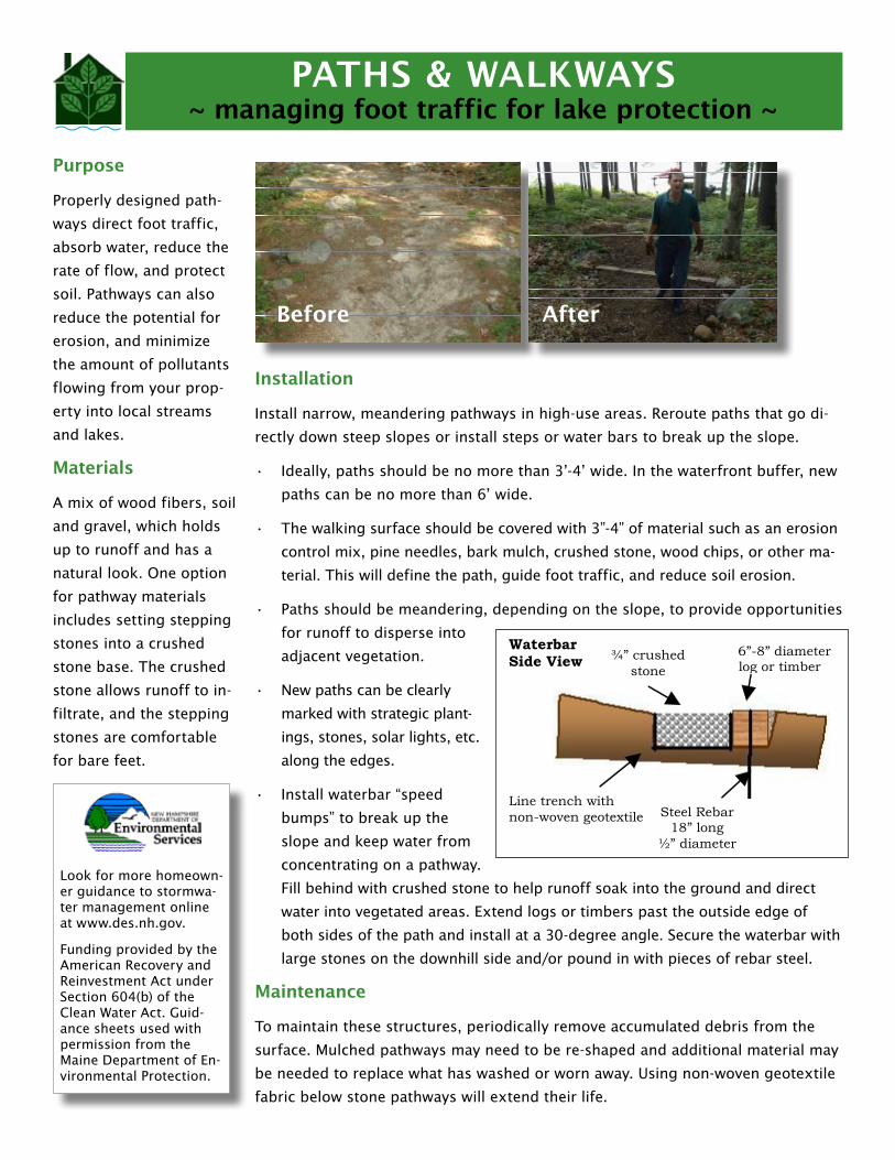
PATHS & WALKWAYS~ managing foot traffic for lake protection ~
Installation
Install narrow, meandering pathways in high-use areas. Reroute paths that go di-
rectly down steep slopes or install steps or water bars to break up the slope.
Ideally, paths should be no more than 3’-4’ wide. In the waterfront buffer, new •
paths can be no more than 6’ wide.
The walking surface should be covered with 3”-4” of material such as an erosion •
control mix, pine needles, bark mulch, crushed stone, wood chips, or other ma-
terial. This will define the path, guide foot traffic, and reduce soil erosion.
Paths should be meandering, depending on the slope, to provide opportunities •
for runoff to disperse into
adjacent vegetation.
New paths can be clearly •
marked with strategic plant-
ings, stones, solar lights, etc.
along the edges.
Install waterbar “speed •
bumps” to break up the
slope and keep water from
concentrating on a pathway.
Fill behind with crushed stone to help runoff soak into the ground and direct
water into vegetated areas. Extend logs or timbers past the outside edge of
both sides of the path and install at a 30-degree angle. Secure the waterbar with
large stones on the downhill side and/or pound in with pieces of rebar steel.
Maintenance
To maintain these structures, periodically remove accumulated debris from the
surface. Mulched pathways may need to be re-shaped and additional material may
be needed to replace what has washed or worn away. Using non-woven geotextile
fabric below stone pathways will extend their life.
Steel Rebar 18” long
½” diameter
6”-8” diameter log or timber
¾” crushed stone
Waterbar Side View
Line trench with non-woven geotextile
Purpose
Properly designed path-
ways direct foot traffic,
absorb water, reduce the
rate of flow, and protect
soil. Pathways can also
reduce the potential for
erosion, and minimize
the amount of pollutants
flowing from your prop-
erty into local streams
and lakes.
Materials
A mix of wood fibers, soil
and gravel, which holds
up to runoff and has a
natural look. One option
for pathway materials
includes setting stepping
stones into a crushed
stone base. The crushed
stone allows runoff to in-
filtrate, and the stepping
stones are comfortable
for bare feet.
Before After Before After

Materials
Rain barrels are available in many sizes and styles,
and range in price from $80 to over $200. Contact
your local hardware store, garden center or nursery,
or order a rain barrel on-line.
Building your own rain barrel is usually the least ex-
pensive option. Several web sites exist with material
lists and clear directions.
Finally, you can simply use an open barrel to collect
rainwater. However, you should use the water within two weeks before mosquitos
have an opportunity to hatch.
Installation
1. Place rain barrel on a level surface. If you have gutters, place the rain barrel
beneath the downspout so the water flows onto the screen on top of the barrel.
You may need to have your downspout cut to an appropriate height above your
rain barrel. If you do not have gutters, find a location where water concentrates
from your roof and place the rain barrel where it will capture this steady stream of
water during rain storms.
2. Elevate your rain barrel by placing it on cinder blocks or a sturdy wooden
frame. Raising the barrel allows the barrel to drain properly, and you can eas-
ily fit a watering can underneath the spout or attach a hose to the spout. Soaker
hoses attached to rain barrels will slowly release water into gardens and recharge
groundwater.
Maintenance
Gutters and downspouts should be clean of debris. Leaves and pine needles can
clog gutters and prevent water from reaching the rain barrel. Furthermore, check
the screen on the rain barrel after each storm event and remove debris that has
plugged the screen.
Freezing water can damage your barrel. Rain barrels should be drained and stored
before freezing weather sets in to prevent ice damage. They can be stored outside
if they are turned upside down and the faucet is covered. Be sure to put some-
thing heavy on your rain barrel so it doesn’t roll away. Rain barrels can also be
stored inside a garage or other protected area.
Purpose
Rain barrels provide an
innovative way to capture
rainwater from your roof,
and store it for later use.
Water collected from rain
barrels can be used to
water lawns, gardens and
indoor plants. This water
would otherwise run off
your roof or through
downspouts and become
stormwa-
ter, pick-
ing up
pollutants
on its way
to a storm
drain, stream or lake. You
can lower your water bill,
conserve well water in the
dry season, and reduce
polluted stormwater
runoff.
RAIN BARRELS~ managing roof runoff in your backyard ~
Look for more homeown-er guidance to stormwa-ter management online at www.des.nh.gov.
Funding provided by the American Recovery and Reinvestment Act under Section 604(b) of the Clean Water Act. Guid-ance sheets used with permission from the Maine Department of En-vironmental Protection.
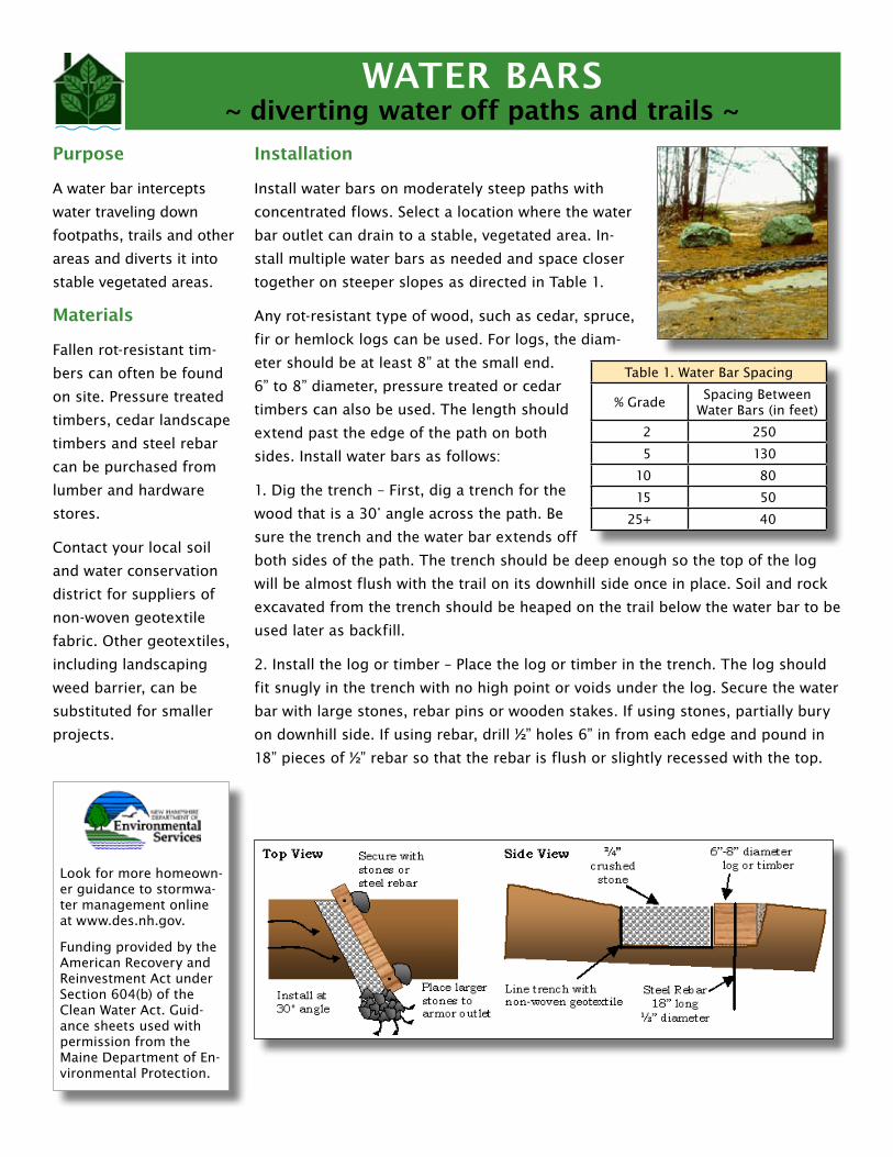
WATER BARS~ diverting water off paths and trails ~
Look for more homeown-er guidance to stormwa-ter management online at www.des.nh.gov.
Funding provided by the American Recovery and Reinvestment Act under Section 604(b) of the Clean Water Act. Guid-ance sheets used with permission from the Maine Department of En-vironmental Protection.
Installation
Install water bars on moderately steep paths with
concentrated flows. Select a location where the water
bar outlet can drain to a stable, vegetated area. In-
stall multiple water bars as needed and space closer
together on steeper slopes as directed in Table 1.
Any rot-resistant type of wood, such as cedar, spruce,
fir or hemlock logs can be used. For logs, the diam-
eter should be at least 8” at the small end.
6” to 8” diameter, pressure treated or cedar
timbers can also be used. The length should
extend past the edge of the path on both
sides. Install water bars as follows:
1. Dig the trench – First, dig a trench for the
wood that is a 30° angle across the path. Be
sure the trench and the water bar extends off
both sides of the path. The trench should be deep enough so the top of the log
will be almost flush with the trail on its downhill side once in place. Soil and rock
excavated from the trench should be heaped on the trail below the water bar to be
used later as backfill.
2. Install the log or timber – Place the log or timber in the trench. The log should
fit snugly in the trench with no high point or voids under the log. Secure the water
bar with large stones, rebar pins or wooden stakes. If using stones, partially bury
on downhill side. If using rebar, drill ½” holes 6” in from each edge and pound in
18” pieces of ½” rebar so that the rebar is flush or slightly recessed with the top.
Purpose
A water bar intercepts
water traveling down
footpaths, trails and other
areas and diverts it into
stable vegetated areas.
Materials
Fallen rot-resistant tim-
bers can often be found
on site. Pressure treated
timbers, cedar landscape
timbers and steel rebar
can be purchased from
lumber and hardware
stores.
Contact your local soil
and water conservation
district for suppliers of
non-woven geotextile
fabric. Other geotextiles,
including landscaping
weed barrier, can be
substituted for smaller
projects.
Table 1. Water Bar Spacing
% GradeSpacing Between
Water Bars (in feet)
2 250
5 130
10 80
15 50
25+ 40

3. Backfill around the water bar – Dig a 12” wide and 6” deep trench along the up-
hill side of the bar. Fill the trench with crushed stone, leaving a few inches of the
timber exposed. Place a flared apron of stones to armor the water bar outlet. Pack
soil and gravel up against the downhill side of the water bar so that the top of it is
flush with the trail. Cover all disturbed soil with seed and mulch or leaf litter.
Maintenance
Water bars should be checked periodically and after storm events to ensure that
material is not eroding behind the structure or at the outlet. Any needed repairs
should be made as soon as possible. Periodically remove accumulated leaves and
debris from behind the water bar.
WATER BARS~ continued ~
Before
After

RAIN GARDENS~ managing roof runoff in your backyard ~
Look for more homeown-er guidance to stormwa-ter management online at www.des.nh.gov.
Funding provided by the American Recovery and Reinvestment Act under Section 604(b) of the Clean Water Act. Guid-ance sheets used with permission from the Maine Department of En-vironmental Protection.
Installation
Rain gardens sizing depends on the area drain-
ing to the garden. To calculate the area needed
for your rain garden:
1. Determine the size of the drainage area.
2. Determine the type of soil at the rain garden
site:
Sandy soil – very gritty; does not roll into •
a ball
Silty soil – smooth and fine; does not roll •
into a ball
Clay soil – very fine, sticky when wet; rolls •
into a ball
3. Multiply the drainage area by the soil sizing factor listed below:
Sandy soil – 0.03; Silty soil – 0.06; Clay soil – 0.10. The resulting number is
the area needed for your rain garden.
Designing
The garden should be bowl-shaped, with the lowest point of the garden no more
than 6” below the surrounding land.
The sides should be gently sloping towards the center to prevent sudden drop-
offs that could lead to erosion problems or walking hazards. Rain gardens are
often placed in a preexisting or created depression within a lawn, or in a location
that receives roof runoff from a downspout.
To avoid flooding improperly sealed foundations, build your rain garden 10’ away
from existing structures, and direct water into the garden with a grassy swale,
infiltration trench, gutter extension or other device.
Rain gardens can be placed in sunny or shady regions of your lawn, but plants
should be chosen accordingly, with the lowest point planted with wet-tolerant spe-
cies, the sides closest to the center planted with moist-tolerant species, and the
edges of the rain garden should be planted with sub-xeric (moist to dry) or xeric
(dry) tolerant plants. After construction of the garden is complete, the entire area
should be covered with a thick layer of mulch, preferably an erosion control mix.
Maintenance
Please note that fertilizer use is restricted within the Protected Shoreland. Fertil-
izer cannot be used within 25 feet of the reference line. From 25 feet to 250 feet,
low phosphate, slow release nitrogen fertilizer may be used on vegetated areas.
Purpose
Rain gardens are at-
tractive and functional
landscaped areas that are
designed to capture and
filter stormwater from
roofs, driveways, and
other hard surfaces. They
collect water in bowl-
shaped, vegetated areas,
and allow it to slowly soak
into the ground. This
reduces the potential for
erosion and minimizes
the amount of pollutants
flowing from your lawn
into streams and lakes.
Materials
Mulches and erosion
control mix are available
from local garden cen-
ters. Native plants can be
purchased from your local
nursery; select species
that thrive in wet soil.
Before
After