Embed Size (px)
Citation preview

INTRODUCTION
The Xilinx XC2064 and XC2018 Logic CeUTM Arrays (LCA) easily accommodate a wide variety of different logic structures. This application note describes the design and entry of two such structures: A binary-toseven-segment display driver and a BCD- (binary coded decimal) to-seven-segment display driver. Although a designer would most likely use an off-the-shelf LED display driver, this application note describes the method of entering a display driver design (more as an example than an actual application). With the Xilinx XACTTM Development System, building the second driver design (BCD) is a simple matter of editing the first (binary).
This application note also describes the Karnaugh map logic entry method available in the XACT Development System. For this design, the Karnaugh map entry saves time by simplifying the logic entry. The engineer can enter his logic directly through the Karnaugh map instead of deriving lengthy equations.
Since the XACT Development System supports macros, a designer may build a logic design from higher level functions. Besides the extensive Xilinx macro library, a designer can choose from custom user-created macro functions. This application note demonstrates how to create two LED driver macros to add to the designer's personal macro library. These LED drivers could then be integrated with other logic structures. For example, a designer might decide to include the drivers with a custom front-panel controller or a custom clock-timer display to minimize overall system chip count.
DESCRIPTION OF THE TWO DESIGNS
Binary-to-Seven-Segment Display Driver,
The first design, as graphically described in Figure 1, consists of logic to decode a four-bit binary input with binary values ranging from OOOOB to 1111 B (0 to 15 decimal). The decoded values drive the seven segments of the LED display to display the corresponding hexadecimal character (0 through F). The "character set" for the binary-to-seven-segment display is shown in Figure 2. Alternate characters
3-29
A Seven-Segment Display Driver
representations are acceptable-especially for the "9", "b" and "d" symbols.
The LED segment drivers have registered outputs driven by the Strobe clock input. The logic drives common cathode LED displays. In other words, a logic "1" lights a particular segment. Conversely, in common anode displays, a logic "0" drives a segment.
BCD-to-Seven-Segment Display Driver
The binary-to-seven-segment display driver created in the first design can be easily edited with the XACT Development System to create a BCD-to-sevensegment display driver. The only modification required involves displaying an error character (in this case, an "e") any time the four-bit value exceeds 1 001 B (9 decimal). The complete "character set" for the BCD display driver is shown in Figure 3.
KARNAUGH MAPS WITHIN THE XACT DEVELOPMENT SYSTEM
For ease-of-use, the XACT Development System supports two forms of logic entry while editing a Configurable Logic Block (CLB). The first is standard Boolean equation entry. The second involves editing values within a Karnaugh map. The two entry methods are tightly coupled, and changes entered under one method are reflected in the other. For example an equation entered in standard Boolean form will be processed by the development system so that the equation also appears in its Karnaugh map representation.
The XACT Development System supports Karnaugh maps with one to four input variables. Editing entries within the Karnaugh map involves placing the mouse cursor in the appropriate entry box and then toggling that box making the entry true or false. Both the truth table and the Boolean equation line are updated to reflect any change entered through the Karnaugh map.
Karnaugh Map Background
Karnaugh maps were originally developed by M. Karnaugh in the early 1950s. Karnaugh maps aid in analyzing and minimizing Boolean logic expressions.
• -

A Seven-Segment Display Driver
w co If }-O .... NM cncncncncn
~--+<'-.----",-------------------------------------'
t-+-_--+r-_--~---i6Bl L _________ J
SEGA
1-+-_-!r_--~----i6Bl L __________ J
SEGB
t-+-_-;~---~----i6Bl L. _________ J
SEGC
1-+-_-!~---~----i6Bl L _________ .J
SEGD
1-+_-!:_-~----i6Bl L.. ________ J
SEGE
1--+-_-!~f---~----i6Bl L __________ .J
SEGF
t--+-_~:--~----ioBI i. __________ .,;
SEGG
, CLB, L _________________________________________ J
However because of the unique logic architecture of a Logic Cell Array, there is no need to minimize logic within a CLB. Logic within an LCA can be directly implemented as a Karnaugh map. Therfore logic minimization using Karnaugh maps will not be discussed here.
For LCA designs, Karnaugh maps provide a quick and concise shorthand notation for defining combinatorial logic functions (although Boolean expressions are possible). This application note describes how to use the Karnaugh entry method to enter the design for the LED driver quickly. Using the Karnaugh map entry method saves a long and tedious step--converting the Karnaugh map into a reduced Boolean expression.
Description of Karnaugh Maps
Within the XACT Development System, Karnaugh maps graphically describe the combinatorial logic inside a CLB. They may have from one to four input variables. The maps consist of a matrix of cells each corresponding to a single minterm of the four possible input variables.
As a simple example, Figure 4 shows a two-input Karnaugh map along with its truth table. The bars on the edges of the Karnaugh map indicate the row or column
3-30
S3
S2
S1
so
STROBE
SEVEN-SEGMENT LED DRIVER
COMMON CATHODE
A
o
SEGA
SEGB
SEGC
SEGD
SEGE
SEGF
SEGG
Figure 1. Basic Seven-Segment LED Driver
0010017 1

for which the specified input variable is true (logic "1"). Notice how the values from the truth table correspond to entries within the Karnaugh map. The first line of the truth table (A=O and B=O) maps into the upper left-hand entry of the Karnaugh map, where again A=O and B=O. The user can "direct map" this value into the Kamaugh map, or he can use the decimal value of the inputs (zero for A=O, B=O) and "position map" the value into position zero of the Karnaugh map.
To enter the simple equation in Figure 4, the user either enters the Boolean equation "A@B" or toggles the upper right-hand and lower left-hand entries in the Karnaugh map to the ON state using the mouse.
I-I 1:1
~~I
~:I 0000 0001
1=1 ~:I
I-~ ~:I
0100 0101
I-I 1:1
I-I ~:I
1000 1001
I-~ I:~
~=I 1:1
1100 1101 0010017 2
This technique becomes even more powerful with each additional input variable. For example Figure 5 shows this same technique applied to a four-input Karnaugh map. For some functions, the Karnaugh map represents a shorthand logic notation over standard Boolean equations.
BINARY·TO·SEVEN·SEGMENT DISPLAY DRIVER
Table 1 lists all of the possible inputs for the sevensegment display driver, including which of the seven segments is driven by each stimulus. An asterisk indicates that the segment output is driven for the specified combination of inputs 83 through 80 .
~-I I:~
~-I ~:I
0010 0011
I-~ 1:1
~-I ~:I
0110 0111
I-I 1:1
I~~
1:1 1010 1011
I-~ I:~
I-~ I:~
1110 1111
Figure 2. Binary·to·Seven-Segment Display Character Set
3-31
--

A Seven-Segment Display Driver
Obviously, converting this table into a series of Boolean logic equations would be tedious. A much simpler method involves entering this information directly into the CLBs using the XACT Editor's Karnaugh map entry facility.
Before delving too deeply into the design entry method, some conventions must first be established. For example if the XACT command sequence Screen(Show(World)) appears, then select the Screen command using the mouse, then the Show command, and lastly the World command. A Done command is implied after each sequence unless the development system prompts for more inputs. From the keyboard, the user merely types Show World (the first command,
0000 0001
0100 0101
1000 1001
ERROR ERROR
I-I I:~
I-I I:~
1100 1101
Screen, does not need to be entered if typing the command from the keyboard) to accomplish the same goal.
Keyboard command abbreviations are often indicated by uppercase highlighted characters in the menus. Abreviations are documented in the Editor section of the XACT LCA Development System Manual.
To generate a blank Karnaugh map within a Configurable LogiC Block (CLB), first select Blk(EditBlk) with the mouse or simply type EB with the keyboard. Then select the CLB in pOSition AH (upper right-hand corner) to work on. This CLB will drive the Segment A (SEGA) signal line of the LED driver.
~-I I:~
~-I ~:I
0010 0011
I-~ 1:1
~-I ~:I
0110 0111
ERROR ERROR
I-I I:~
I-I I:~
1010 1011
ERROR ERROR
I-I I:~
I-I I:~
1110 1111
0010017 2
Figure 3. BCD-to-Seven-Segment Display Character Set
3-32

0010017 4
0010017 5
0010017 13
(
TRUTH TABLE F
DECIMAL B A F A
POSITION
DIRECT ·'0::"'·: ':'0' :0· ·O+-----~ 0
~ ~ 6 ~ B",f-----1f-o-l 3 1 1 0
POSITION
o
2 3
POSITION MAP
KARNAUGH MAP
BOOLEAN EQUATION =-A·B+A.-B =A@B
Figure 4. Two·Variable Karnaugh Map
TRUTH TABLE F
DECIMAL D C B A F A
0 0 0 0 0 0 1 0 0 0 1 0 0 0 0 2 0 0 1 0 1 3 0 0 1 1 0
C 4 0 1 0 0 1 5 0 1 0 1 1 6 0 1 1 0 1 0 7 0 1 1 1 1 DIRECT D
p;f:::"'tf::":"" ::':':1:")" 'Q :"::·(f ':':'::0·· Q 0 0 0 9 1 0 0 1 0 KARNAUGH MAP
B 10 1 0 1 0 0 0 3 11 1 0 1 1 1 12 1 1 0 0 0 13 1 1 0 1 1 POSITION 4 5 7 6 14 1 1 1 0 0 15 1 1 1 1 1 12 13 15 14
~ - 8 9 11 10
"-POSITION
POSITION MAP
Figure 5. Four-Variable Karnaugh Map
DECIMAL S3 S2 S1 SO A B C D E F G
0 0 0 0 0 · · · · · · 1 0 0 0 1 · · A 2 0 0 1 0 · · · · · 3 0 0 1 1 · · · · · 4 0 1 0 0 · · · · 5 0 1 0 1 · · · · · 6 0 1 1 0 · · · · · · 7 0 1 1 1 · · · 8 1 0 0 0 · · · · · · · 9 1 0 0 1 · · · · ·
10 1 0 1 0 · · · · · · 11 1 0 1 1 · · · · · 12 1 1 0 0 · · · · D 13 1 1 0 1 · · · · · 14 1 1 1 0 · · · · · 15 1 1 1 1 · · · ·
Table 1. Input Table for Binary-To-Seven-Segment Display
3-33
.. -

A Seven-Segment Display Driver
Since each segment of the LED driver requires a function of four input variables, change the base configuration of the CLB from its default configuration (two functions, each using three of the five available input variables). Select Config(Base(F» to do this. Now the CLB is configured to be a single function using four out of the five possible variables.
To create a blank Karnaugh map, select Config(Order(F(A(B(C(D»))))) (remember to add the implied Done). The display should appear like Figure 6 with a blank Karnaugh map appearing in the lower left hand corner.
Configure the SEGA CLB by selecting "Q" to drive the X output. In addition, use the "K" clock input to clock the storage element.
To save effort entering this deSign, copy the configuration in the SEGA CLB to six other CLBs (one each for the remaining six LED segments). First, select Screen(Switch) to switch to the physical interconnect editor. Then, select Blk(Copyblk) and click on block AH (which is the SEGA block). Copy this block to CLB blocks BH through GH (all along the right-hand edge of the die). Remember to select Done when complete. Again select Screen(Switch) to continue editing the SEGACLB.
Using the information in Table 1, the user can enter the design directly into the Karnaugh map. For clarity and an as example, entering the data for Segment A (SEGA) of the seven-segment display is described.
Table 2 contains the binary values of the input variables A, B, C, and 0 as well as the corresponding logic output F for SEGA. All of the possible values ranging from OOOOB to 1111 B are numbered with their corresponding decimal values. In addition, Figure 7a shows where each of the binary inputs is located within the Karnaugh map using the decimal values of the 4-bit binary input. Figure 7b details how the logic for SEGA maps into the Karnaugh map.
Using the mouse, place the mouse cursor inside the upper left block of the Karnaugh map and toggle that block on (bright yellow) with the mouse select button. The logic for SEGA (when all of the inputs are logiC "0") has just been set. The truth table to the left of the Karnaugh map and the Boolean equation line at the bottom of the screen should both reflect the change made in the Karnaugh map.
Continue toggling on the indicated blocks for the remaining values, just as shown in Figure 7b. This is much simpler than typing the Boolean equation for SEGA:
SEGA = -C*-A+C*B+O*-A+-O*B+-O*C*A*-C*-B
Repeat this same process for the six remaining CLBs. The Karnaugh maps should appear like those shown in Figure 8.
Now that each of the segment drivers has been configured, name each CLB with its corresponding segment identity. For Segment A, type
NAMEB HA SEGA (Enter).
The name SEGA should appear in block AH. To save the designer time and effort, the development system keeps a running stack of the latest command line entries. This way, a user can pull up the last few commands and edit them to enter similar commands. For example to name Segment B, merely press the up cursor button. The line previously entered will appear on the command line. Edit the command line using the
x Y
A~ Q ~ Q SET RES D BlK:AH ClK
DCBA F A A:
X XXX L
D{ale
B: C: D' K:
B X: Y:
F=
0010017 6
Figure 6. Blank Karnaugh Map In CLB Display
DECIMAL D C B A F
0 0 0 0 0 * 1 0 0 0 1 2 0 0 1 0 * 3 0 0 1 1 * 4 0 1 0 0 5 0 1 0 1 * 6 0 1 1 0 * 7 0 1 1 1 * 8 1 0 0 0 * 9 1 0 0 1 *
10 1 0 1 0 * 11 1 0 1 1 12 1 1 0 0 * 13 1 1 0 1 14 1 1 1 0 * 15 1 1 1 1 *
0010017 14
Table 2. Truth Table Specifically for Segment A
3-34

left and right cursor keys and the insert (Ins) and delete (Del) keys to read
NAMEB HB SEGB.
Now press the ENTER key. Continue naming the remaining blocks in the same manner.
Add the required networks using the Addnet command. Connect a network called SO to the A-input of each CLB in the design, one called S1 to the B-input, one called S2 to the C-input, and one called S3 to the O-input. Attach all of the K clock lines together on a net called Strobe.
For the X-output from each CLB, add an output network using a name specific for each segment output. For example, attach a network called A_Out to the X-output from the SEGA CLB.
VALIDATING THE DESIGN
Before a section of logic is saved as a macro function, its function should be thoroughly verified. Without verification, logic bugs could potentially be passed from one design to another (a veritable digital design influenza). Using the macro library, a designer builds his logic in debugged modules.
Modular logic design accomplishes many of the same goals as modular software design. Modularity helps speed development by isolating errors to specific modules, making the system easier to debug. By using validated modules throughout his design, the designer reduces the time and frustration of the hardware debug cycle. Obviously validating macros is important.
The minimum validation that should be applied to a macro function is the Design Rule Checker (ORC). To invoke the ORC for the LED driver design just entered, select Misc(DRC) from the LCA Editor. Warnings about missing sources or loads may be ignored if the specified networks are known not to have them. For example, in this design, the DRC indicates that networks SO, S1, S2, S3, and Strobe have no sources while networks A_Out through G_Out have no loads. Warnings about PIPs (programmable interconnect points) may be ignored if some of the networks have not been routed (as is the case with this design example).
A much better way to validate the design involves either the simulator (P-SILOSTM), the in-circuit emulator (XACTORTM), or the download cable. To validate the design with the simulator, run the simulation generator program (SimGen in the Executive Program menu). Then, using any standard text editor, edit the data file (<filename>.OAT) to include valid stimuli to test the
3-35
design. Figure 9 shows the stimuli used to verify the LED driver. Running a simulation based on these stimuli produces the graphical output shown in Figure 1 0.
Emulation is even simpler. It involves downloading the design into a system and testing it there for functionality.
After verifying the design, enter the LCA Editor by Selecting Editlca from the main Executive menu. Now, to save the binary-to-seven-segment display drive in the macro library, select Misc(Cutmacro). When the development system prompts for a file name, enter 7SEG_BLC for a seven-segment display driver (7SEG_) using binary (B) input with latched output (L) to a common cathode (C) display.
To save the desired portion of logiC under this macro name, select the seven CLBs used in this design using the mouse. Select blocks AH through GH. Select Done when complete. The Cutmacro command automatically picks up the routing attached to the specified blocks (as well as any corresponding block and net names) and creates an ASCII text file containing all the macro information. A portion of the ASCII macro file called 7SEG_BLC.MAC appears in Figure 11. The Cutmacro command also appends the file extension .MAC to a macro file.
Once in ASCII form, the designer can use any standard .' text editor to edit the newly created macro file. For example, the designer may decide to change the default network or block names.
0 1
4 5
12 13
0010017 7> 8 9
3 2
7 6
15 14
11 10
'--v---' B
Figure 7a. Position Map for a Four-Variable Karnaugh Map
0010017 7b
• • • • • '--v---'
B
Figure 7b. Segment A Logic Mapped Into Karnaugh Map
-

A Seven-Segment Display Driver
The newly created macro file can now be used just like any standard macro library entry merely by selecting Misc(Macro» and choosing macro 7SEG_BlC.
BCO-TO-SEVEN-SEGMENT OISPLAY ORIVER
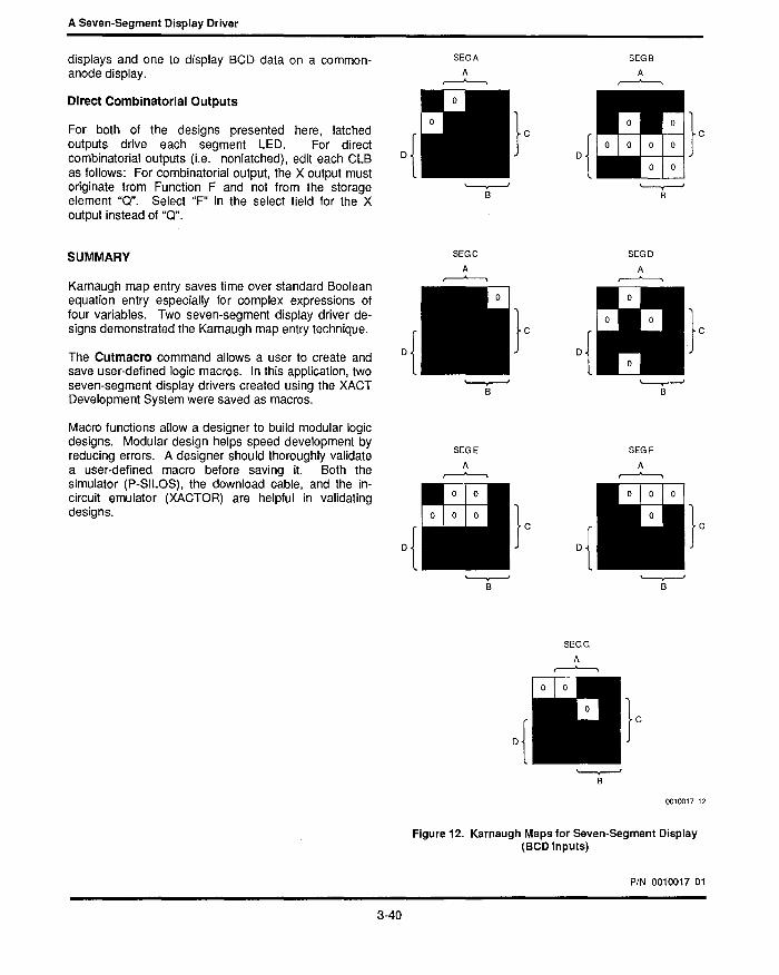
Table 3 indicates which of the seven-segments are lighted by each of the sixteen input combinations. Notice that combinations 10 through 15 are identical (the error symbol "e"). Modifying the binary display driver to make it a BCD display driver is quite simple. Positions 10 through 15 in each Karnaugh map for Segments A through G must be modified. To display the error symbol, all of the lED segments except for Segment C (SEGC) are lighted. The edited Karnaugh maps for the BCD driver appear in Figure 12.
Edit the Karnaugh maps for all of the lED segments (SEGA through SEGG) to reflect the changes and then perform a Design Rule Check to verify the design.
Once verified, save this new design as another macro, this time called BCDJLC for BCD to seven-segment display (BCD_7) with latched outputs (l) for a common cathode display (C).
OTHER POSSIBLE MODIFICATIONS
Common-Anode Displays
The logic for both lED display drivers presented here
SEGA
A r--"---o.
'-----v--' B
• • • ••
'-----v--' B
SEGE
A r--"---o.
}c
SEGB
A r--"---o.
o{II}' '-----v--'
B
SEGD
A r--"---o.
o~}' {~ '-----v--'
B
SEGF
A r--"---o.
specifies active-high outputs (positive logic). Positive D {
logic drives common-cathode displays by sending a logic "1" to the appropriate segment. To drive common-anode displays, however, the logic sense must be inverted. In other words, the positive logic equations
}c D{
}c
must be converted to negative logic equations.
Simply inverting every entry within each Karnaugh map for each ClB accomplishes this. However, in this case, editing the Boolean equation is much easier. While editing the correct ClB, select Config(Editeq(F» and use the left and right cursor keys and the insert (Ins) and delete (Del) keys to edit the equation. For example, to invert the equation for SEGA, change the equation from
to
F = -(-C*-A+C*B+O*-A+-D*B+-O*C* A+O*-C*-B)
by adding a "-(" to the front of the equation and a ")" to the back of the equation. Do this for each segment.
Thus, two new macros can be created-one for a binaryto-seven-segment display driver for common-anode
3-36
'-----v--' B
SEGG
A r--"---o.
'-----v--' B
'-----v--' B
0010017 8
Figure 8. Karnaugh Map Seven-Segment Display (Binary Inputs)

0010017 15
DECIMAL 53 52 51 50 A B C D E F G
0 0 0 0 0 · · · · · 1 0 0 0 1 · · A 2 0 0 1 0 · · · · · 3 0 0 1 1 · · · · · 4 0 1 0 0 · · · · 5 0 1 0 1 · · · · · 6 0 1 1 0 · · · · · · 7 0 1 1 1 · · · 8 1 0 0 0 · · · · · · · 9 1 0 0 1 · · · · ·
10 1 0 1 0 · · · · · · 11 1 0 1 1 · · · · · · 12 1 1 0 0 · · · · · · 13 1 1 0 1 · · · · · · 14 1 1 1 0 · · · · · · 15 1 1 1 1 · · · · · ·
Table 3. Input Table for BeD-To-Seven-Segment Display
$ $ Simulation file for design 'KARANAUGH.LCA' type '2064c68-1' $ Created by XACT Ver. 1.1 at 15:01:43 MAR 23, 1986 $ !INPUT KARANAUGH.sim
$ INPUTS: Strobe .CLK 0 SO 100 Sl 200 SO .REP 0 GLOBAL.RESET .eLK 0 Sl 1 SO $ Initial pulse to reset latches
. PATTERN S3 S2 Sl SO 0 0 0 0 0 $hex 0 500 0 0 0 1 $hex 1 1000 0 0 1 0 $hex 2 1500 0 0 1 1 $hex 3 2000 0 1 0 0 $hex 4 2500 0 1 0 1 $hex 5 3000 0 1 1 0 $hex 6 3500 0 1 1 1 $hex 7 4000 1 0 0 0 $hex 8 4500 1 0 0 1 $hex 9 5000 1 0 1 1 $hex A 5500 1 0 1 1 $hex B 6000 1 1 0 0 $hex C 6500 1 1 0 1 $hex D 7000 1 1 1 0 $hex E 7500 1 1 1 1 $hex F .EOP
.MONITOR Strobe SO Sl S2 S3 ; A_Out B_Out C_Out D_Out E_Out F_Out G_Out
.GRAPH Strobe SO Sl S2 S3 ; A_Out B_Out C_Out D_Out E_Out F_Out G_Out
Figure 9. Simulator Stimulus File to Validate Binary-to-Seven-Segment Display Design
3-37
--

A Seven-Segment Display Driver
A_OUT
8_ooT n C_OUT U LSl D_OUT
E_OUT
F_OUT I U U G_OUT U U
HEXVALUE 0 1 2 3 4 5. 6 7 8 9 A 8 C D E F
ABCDEFG ABCDEFG
0000000 0000000 8888 UUUUUUU 8888 UUUUUUU
TIME 32 1 0 TTTTTTT TIME 32 1 0 TTTTTTT
0 o 000 1 1 1 1 1 1 0 0 4035 1 000 1 1 1 1 1 1 1 8 500 000 1 1 1 1 1 1 1 0 4500 1 0 0 0 1 1 1 1 1 1 1 535 0001 0110000 1 4535 1 0 0 1 11 1 001 1 9
1000 001 0 0110000 5000 1 0 0 1 1 1 1 00 1 1 1035 o 0 1 0 1 1 01 1 01 2 5035 101 0 1 1 1 01 1 1 A 1500 o 0 1 1 1 1 01 1 01 5500 101 0 1 1 1 0 1 11 1535 o 0 1 1 1111001 3 5535 1 01 1 o 0 1 1 1 11 C 2000 01 00 1 1 1 1 00 1 6000 1 0 1 1 o 0 1 1 1 11 2035 o 1 0 0 0110011 4 6035 1 1 00 1 0 0 1 1 1 0 C 2500 o 1 0 1 0110011 6500 1 1 00 1 001 1 1 0 2535 o 1 0 1 1011011 5 6535 1 1 0 1 o 1 1 1 1 0 1 D 3000 01 1 0 1 0 1 1 01 1 7000 1 1 0 1 o 1 1 1 1 0 1 3035 o 1 1 0 1 0 1 1 1 1 1 6 7035 1 1 1 0 1 0 0 1 1 1 1 E 3500 01 1 1 1 0 1 1 1 1 1 7500 1 1 1 0 1 0 0 1 1 1 1 3535 o 1 1 1 1110000 7 7535 1111 1 0001 1 1 F 4000 1 000 1 1 1 0 000
Figure 10. Timing Diagram Output from P-SILOS for Binary-to Seven-Segment Display Driver (Diagram is used to validate logic)
3-38
0010017 10
0010017 lOA

; Cutmacro: KARANAUGH.LCA, XACT 1.1, 15:47:57 MAR Parameter NAME? Enter instance name: Parameter NET S3 Select S3 net Parameter NET S2 Select S2 net: Parameter NET SI Select SI net: Parameter NET SO Select SO net: Parameter NET Strobe Select Strobe block: Parameter CLB ? Select SEGA block: Parameter CLB ? Select SEGB block: Parameter CLB ? Select SEGC block: Parameter CLB ? Select SEGD block: Parameter CLB ? Select SEGE block: Parameter CLB ? Select SEGF block: Parameter CLB ? Select SEGG block: Editblk %7 C X:F Y: F:A:B:C:D Q:FF SET: RES: CLK:K Eq F = -C*-A+C*B+D*-A+-D*B+-D*C*A+D*-C*-B Endblk Editblk %8
• Editblk %l3 Base F Config X:F Y: F:A:B:C:D Q:FF SET: RES: CLK:K Equate F = -C*B+D*A+D*B+D*-C+-D*C*-A+-D*C*-B Endblk Addpin %2 %7.A %8.A %9.A %10.A %11.A %12.A %13.A Addpin %3 %13.B %12.B %11.B %10.B %9.B %8.B %7.B Addpin %4 %7.C %8.C %9.C %10.C %11.C %12.C %13.C Addpin %5 %13.D %12.D %11.D %10.D %9.D %8.D %7.D Addpin %6 %7.K %8.K %9.K %10.K %ll.K %12.K %13.K
23,
}
}
1986
Parameterized nets, default names and prompt messages
Parameterized blocks and prompt messages
Logic Definition
Parameterized net names and connections
FIgure 11. Portion of Newly Created LED Driver Macro (7SEG_BLC)
3-39
--
A Seven-Segment Display Driver
displays and one to display BCD data on a commonanode display.
Direct Combinatorial Outputs
For both of the designs presented here, latched outputs drive each segment LED. For direct combinatorial outputs (Le. nonlatched), edit each CLB as follows: For combinatorial output, the X output must originate from Function F and not from the storage element "Q". Select "F" in the select field for the X output instead of "Q".
SUMMARY
Kamaugh map entry saves time over standard Boolean equation entry especially for complex expressions of four variables. Two seven-segment display driver designs demonstrated the Karnaugh map entry technique.
The Cutmacro command allows a user to create and save user-defined logic macros. In this application, two seven-segment display drivers created using the XACT Development System were saved as macros.
Macro functions allow a designer to build modular logic deSigns. Modular design helps speed development by reducing errors. A designer should thoroughly validate a user-defined macro before saving it. Both the simulator (P-SILOS), the download cable, and the incircuit emulator (XACTOR) are helpful in validating designs.
3-40
SEGA
A ~
SEGC
A ~
SEGE
A ~
SEGB
A ~
o{!I}c
SEGD
A ~ • • •
• •
SEGG
A ~
SEGF
A ~
0010017 12
Figure 12. Karnaugh Maps for Seven-Segment Display (BCD Inputs)
PIN 0010017 01