Embed Size (px)
Citation preview
Jonathan LEDY, Mahamadi SAVADOGO, Hervé BOEGLEN, AnneMarie POUSSARD, Benoît HILT, Rodolphe VAUZELLE
A semideterministic channel model for VANETs simulations
Laboratoire MIPS/GRTCUniversité de Haute Alsace,
France
Laboratoire XLIM/SICUniversité de Poitiers,
France
CNRS
[email protected]poitiers.fr
2
Context
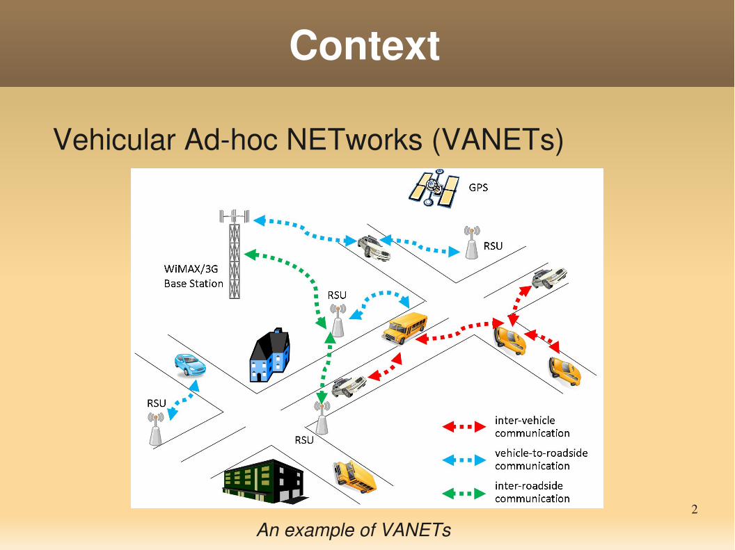
Vehicular Adhoc NETworks (VANETs)
An example of VANETs
3
Context
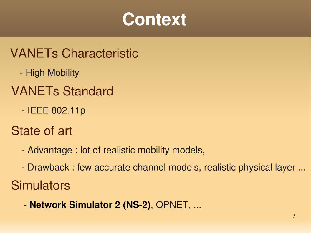
VANETs Characteristic High Mobility
Simulators Network Simulator 2 (NS2), OPNET, ...
State of art Advantage : lot of realistic mobility models,
Drawback : few accurate channel models, realistic physical layer ...
VANETs Standard IEEE 802.11p
4
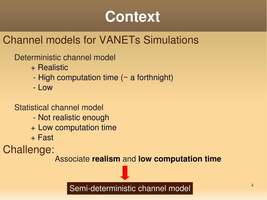
ContextChannel models for VANETs Simulations
Deterministic channel model + Realistic
High computation time (~ a forthnight) Low
Statistical channel model Not realistic enough + Low computation time + Fast
Challenge: Associate realism and low computation time
Semideterministic channel model
Overview
1. Statistical model (SCMEUM)
2. Deterministic simulator (CRT)
3. Contribution: semideterministic model (UMCRT)
4. UMCRT Evaluation
5. Conclusion and Future Work
6
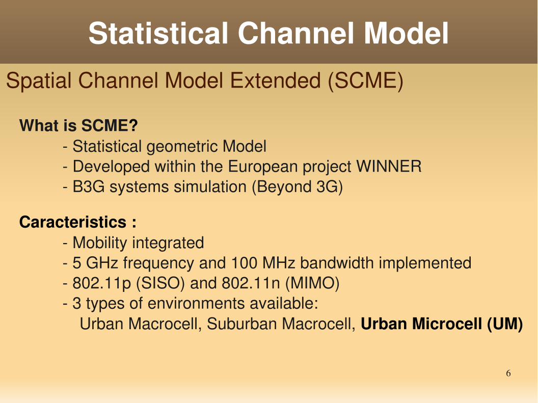
Statistical Channel ModelSpatial Channel Model Extended (SCME)
What is SCME? Statistical geometric Model
Developed within the European project WINNER B3G systems simulation (Beyond 3G)
Caracteristics : Mobility integrated 5 GHz frequency and 100 MHz bandwidth implemented 802.11p (SISO) and 802.11n (MIMO) 3 types of environments available:
Urban Macrocell, Suburban Macrocell, Urban Microcell (UM)
7
Realistic Simulator
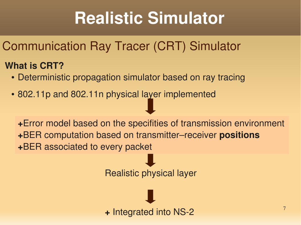
What is CRT?● Deterministic propagation simulator based on ray tracing
● 802.11p and 802.11n physical layer implemented
+ Integrated into NS2
Communication Ray Tracer (CRT) Simulator
Realistic physical layer
+Error model based on the specifities of transmission environment +BER computation based on transmitter–receiver positions+BER associated to every packet
8
Realistic Simulator
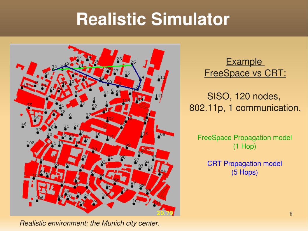
FreeSpace Propagation model(1 Hop)
CRT Propagation model(5 Hops)
Realistic environment: the Munich city center.
Example FreeSpace vs CRT:
SISO, 120 nodes, 802.11p, 1 communication.
9
UMCRTSemideterministic Model
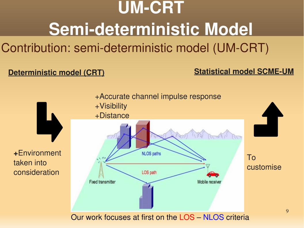
Contribution: semideterministic model (UMCRT)
Deterministic model (CRT)
Our work focuses at first on the LOS – NLOS criteria
Statistical model SCMEUM
+Accurate channel impulse response+Visibility+Distance
To customise
+Environment taken into consideration
10
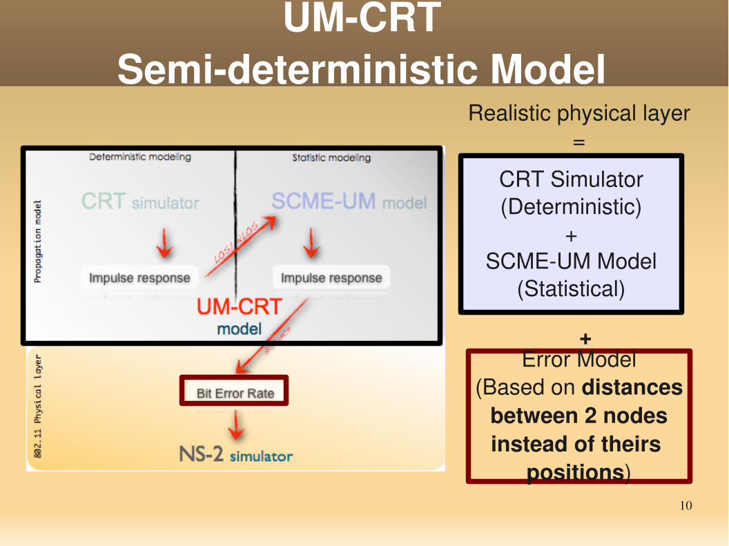
CRT Simulator(Deterministic)
+SCMEUM Model
(Statistical)
UMCRTSemideterministic Model
Realistic physical layer=
Error Model(Based on distances between 2 nodes instead of theirs
positions)
+
11
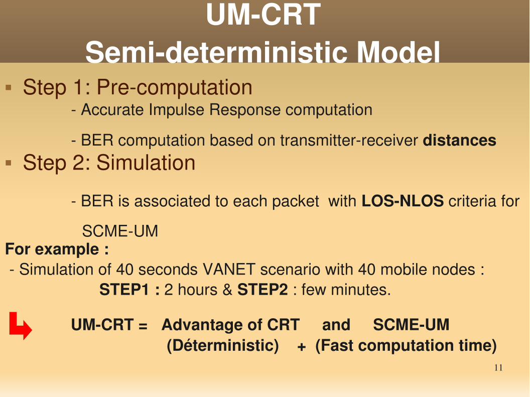
UMCRTSemideterministic Model
Step 1: Precomputation Accurate Impulse Response computation
BER computation based on transmitterreceiver distances
BER is associated to each packet with LOSNLOS criteria for
SCMEUM
Step 2: Simulation
For example : Simulation of 40 seconds VANET scenario with 40 mobile nodes : STEP1 : 2 hours & STEP2 : few minutes.
UMCRT = Advantage of CRT and SCMEUM (Déterministic) + (Fast computation time)
12
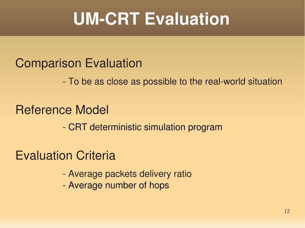
UMCRT Evaluation
Evaluation Criteria Average packets delivery ratio Average number of hops
Reference Model CRT deterministic simulation program
Comparison Evaluation To be as close as possible to the realworld situation
13
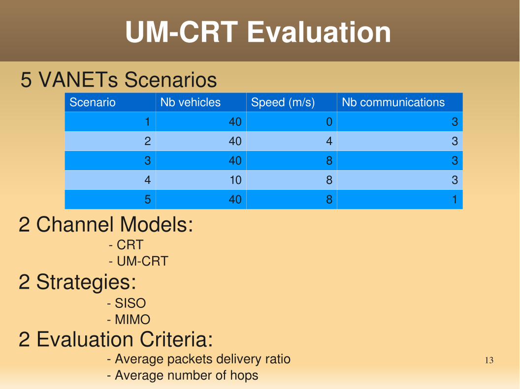
UMCRT Evaluation5 VANETs Scenarios
2 Channel Models: CRT UMCRT
2 Evaluation Criteria: Average packets delivery ratio Average number of hops
SISO MIMO
2 Strategies:
Scenario Nb vehicles Speed (m/s) Nb communications
1 40 0 3
2 40 4 3
3 40 8 3
4 10 8 3
5 40 8 1
14
UMCRT Evaluation (SISO)
1 2 3 4 5
0
10
20
30
40
50
60
70
80
90
100
Packets Delivery Ratio
CRT
UMCRT
Scenario
Pac
kets
Del
ive r
y R
atio
(%)
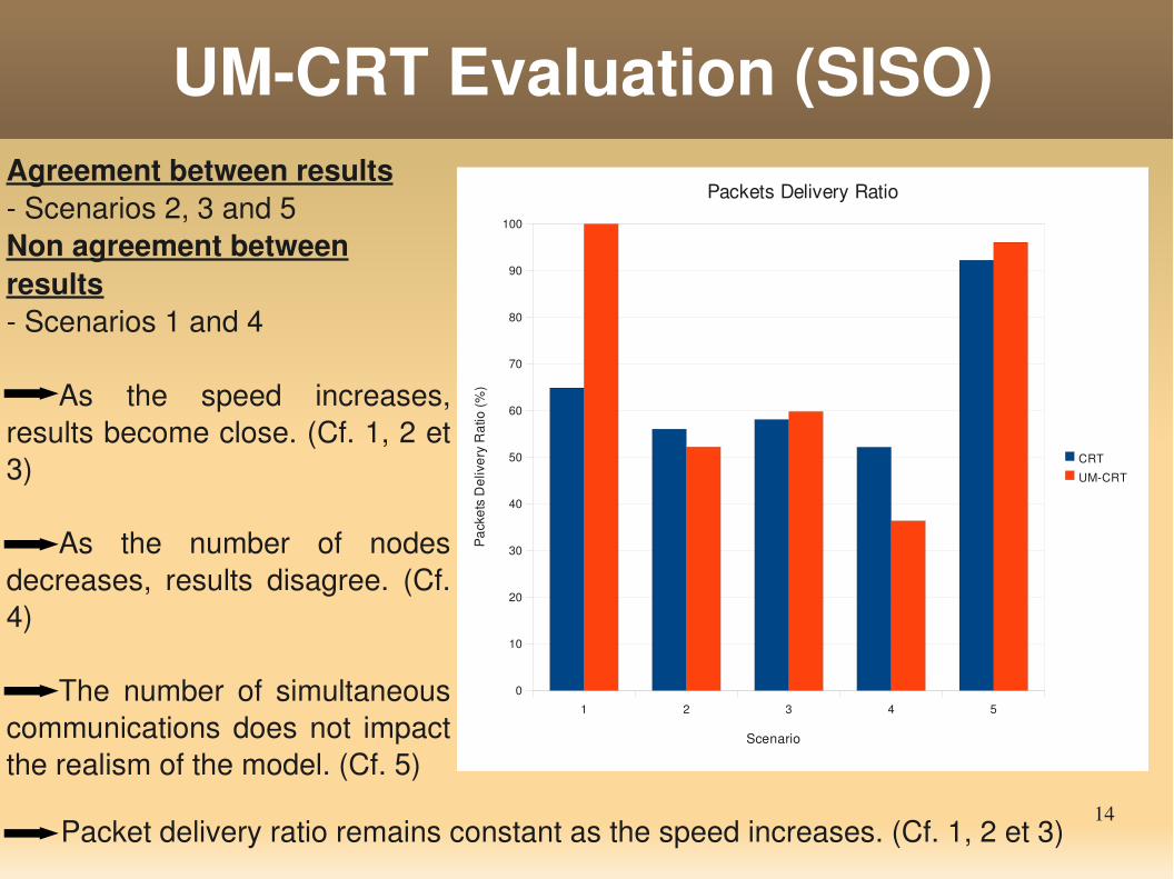
Agreement between results Scenarios 2, 3 and 5Non agreement between results Scenarios 1 and 4
As the speed increases, results become close. (Cf. 1, 2 et 3)
As the number of nodes decreases, results disagree. (Cf. 4)
The number of simultaneous communications does not impact the realism of the model. (Cf. 5)
Packet delivery ratio remains constant as the speed increases. (Cf. 1, 2 et 3)
15
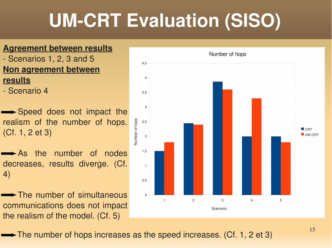
UMCRT Evaluation (SISO)Agreement between results Scenarios 1, 2, 3 and 5Non agreement between results Scenario 4
Speed does not impact the realism of the number of hops. (Cf. 1, 2 et 3)
As the number of nodes decreases, results diverge. (Cf. 4)
The number of simultaneous communications does not impact the realism of the model. (Cf. 5)
1 2 3 4 5
0
0,5
1
1,5
2
2,5
3
3,5
4
4,5
Number of hops
CRT
UMCRT
Scenario
Num
ber o
f hop
s
The number of hops increases as the speed increases. (Cf. 1, 2 et 3)
16
UMCRT Evaluation (MIMO)
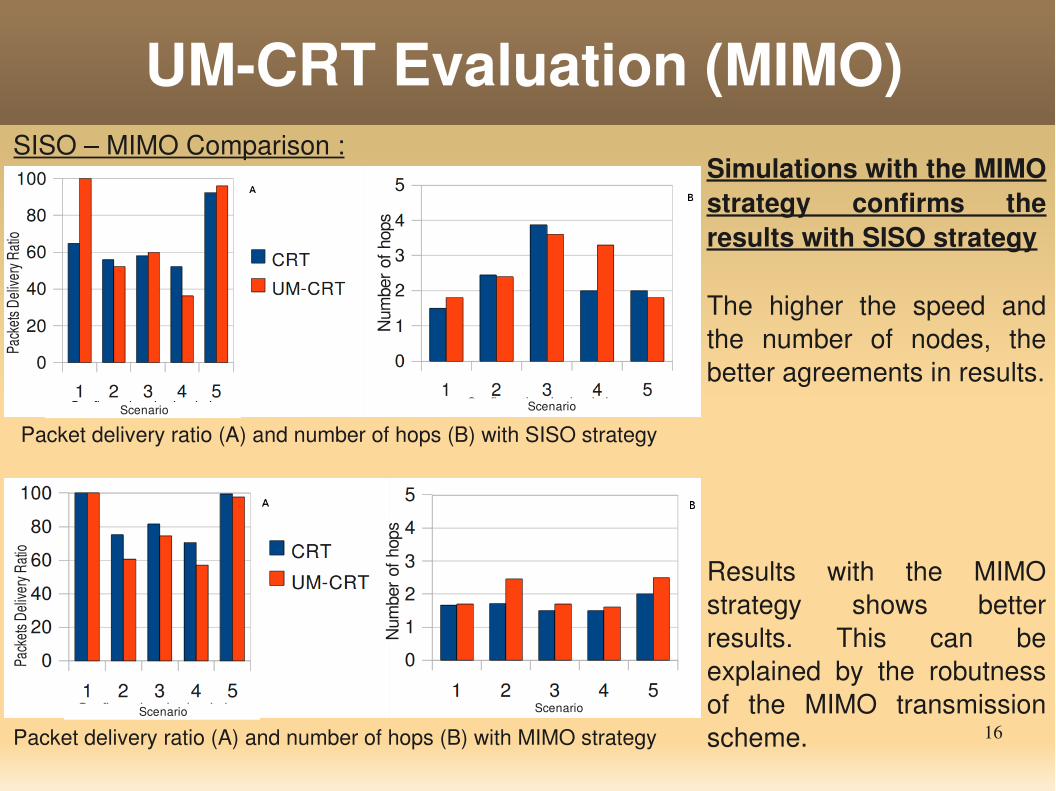
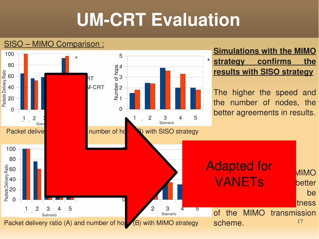
Packet delivery ratio (A) and number of hops (B) with SISO strategy
Packet delivery ratio (A) and number of hops (B) with MIMO strategy
SISO – MIMO Comparison :Simulations with the MIMO strategy confirms the results with SISO strategy
The higher the speed and the number of nodes, the better agreements in results.
Results with the MIMO strategy shows better results. This can be explained by the robutness of the MIMO transmission scheme.
Num
ber
of h
ops
N
umbe
r of
hop
s
Scenario Scenario
Scenario Scenario
Pack
ets D
elive
ry Ra
tioPa
ckets
Deli
very
Ratio
17
Simulations with the MIMO strategy confirms the results with SISO strategy
The higher the speed and the number of nodes, the better agreements in results.
Results with the MIMO strategy shows better results. This can be explained by the robutness of the MIMO transmission scheme.
UMCRT Evaluation
Packet delivery ratio (A) and number of hops (B) with SISO strategy
Packet delivery ratio (A) and number of hops (B) with MIMO strategy
SISO – MIMO Comparison :
Num
ber
of h
ops
N
umbe
r of
hop
s
Scenario Scenario
Scenario Scenario
Pack
ets D
elive
ry Ra
tioPa
ckets
Deli
very
Ratio Adapted for
VANETs
18
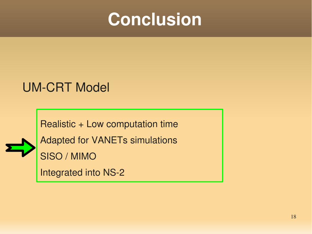
Conclusion
UMCRT Model
Realistic + Low computation time
Adapted for VANETs simulations
SISO / MIMO
Integrated into NS2
19
Future Work
Reduce precomputation time
Find new relevant criteria extracted from IR
Jonathan LEDY, Mahamadi SAVADOGO, Hervé BOEGLEN, AnneMarie POUSSARD, Benoît HILT, Rodolphe VAUZELLE
A semideterministic channel model for VANETs simulations
Laboratoire MIPS/GRTCUniversité de Haute Alsace,
France
Laboratoire XLIM/SICUniversité de Poitiers,
France
CNRS
[email protected]poitiers.fr
21
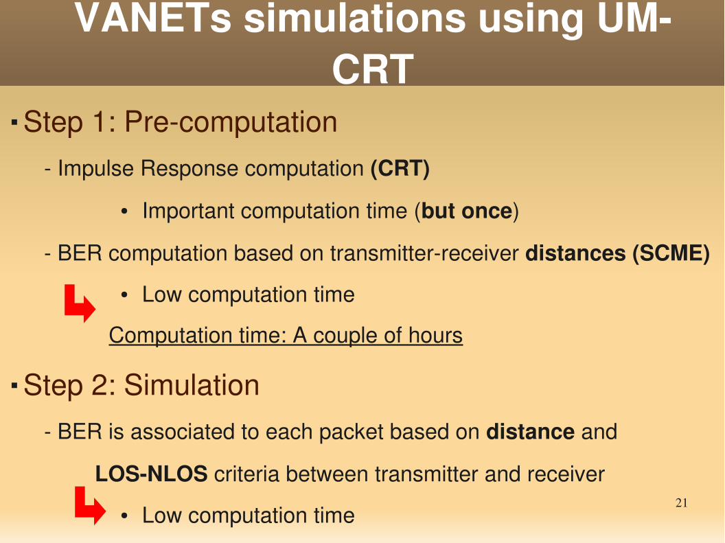
VANETs simulations using UMCRT
Step 1: Precomputation Impulse Response computation (CRT)
● Important computation time (but once)
BER computation based on transmitterreceiver distances (SCME)
● Low computation time
Computation time: A couple of hours
Step 2: Simulation BER is associated to each packet based on distance and
LOSNLOS criteria between transmitter and receiver
● Low computation time
Computation time: few minutes