Embed Size (px)
Citation preview

A Secure and Privacy-Friendly IP-basedEmergency Services Architecture
Dissertation
for the award of the degree’Doctor rerum naturalium’
at the Georg-August-Universitat Gottingen
within the doctoral programme/doctoral degree programmeof the Georg-August University School of Science (GAUSS)
submitted by
Hannes Tschofenig
from Villach, Austria
Gottingen, November 2019

Thesis advisory committee
Prof. Dr. Xiaoming Fu, Georg-August Universitat Gottingen
Prof. Dr. Dieter Hogrefe, Georg-August Universitat Gottingen
Members of the examination board
Referee: Prof. Dr. Xiaoming Fu, Georg-August Universitat Gottingen
Co-referee: Prof. Dr. Dieter Hogrefe, Georg-August Universitat Gottingen
Co-referee: Prof. Dr. Thomas Schmidt, HAW Hamburg
Other members of the Examination Board
Prof. Dr.-Ing. Marcus Baum, Georg-August Universitat Gottingen
Prof. Dr. Ramin Yahyapour, Georg-August Universitat Gottingen
Prof. Dr.-Ing. Delphine Reinhardt, Georg-August Universitat Gottingen
Day of the oral examination: 28. November 2019

Abstract
Emergency services support is one of the most valued features of the public switchedtelephone network. With the transition to IP-based communication the opportunity tore-design the emergency services communication architecture emerged. It was a chance tooffer more features with improved security and privacy properties.
This dissertation makes a contribution to the design of an IP-based emergency servicesarchitecture that offers international applicability, and multi-media support. Due to theextended functionality emergency calls can also be triggered by vehicles and Internet ofThings devices. Security and privacy was taken care off during the work on this architecture.


Zusammenfassung
Die Unterstutzung von Notrufdiensten ist eine der am meisten geschatzten Funktio-nen des offentlichen Telefonnetzes. Mit dem Ubergang zur IP-basierten Kommunikationwerden neue Geschaftsmodelle und Funktionen untersucht. Diese Entwicklung bietet dieMoglichkeit einer Neugestaltung, die unter anderem auch sicherer ist und bessere Eigen-schaften fur den Datenschutz bietet.
Diese Dissertation leistet einen Beitrag zur Entwicklung einer auf dem Internet Pro-tokoll basierenden Notrufarchitektur, welche international anwendbar ist und eine Multime-diafahigkeit besitzt. Durch die erweiterte Funktionalitat konnen Notrufe auch von Fahrzeu-gen und von Internet der Dinge ausgelost werden. Auf Sicherheit und Datenschutz wurdeschon bei der Entwicklung der Architektur Rucksicht genommen.


Acknowledgements
I would like to thank my supervisor Prof. Dr. Xiaoming Fu for inviting me to work in hisgroup, and for the support he provided to me over the years. During that time we contributedto the research community and also to standards developing organizations. I would also liketo thank Prof. Dr. Dieter Hogrefe for his guidance regarding my PhD thesis. My gratitudealso goes to all members of the examination board.
During the work on my thesis I met many researchers, product developers, standardiza-tion experts, practitionaires from emergency services authorities, regulators, politicians, andeven those who benefitted from the existence of the emergency services infrastructure. Insummary, I was fortunate to get to know so many great people who dedicated their life toimprove the emergency services infrastructure to make a difference for others.
In particular, I would like to thank those who worked with me in the Internet Engineer-ing Task Force (IETF), the European Emergency Number Association (EENA), and theNational Emergency Number Association (NENA).
From February 2005 to March 2010 I co-chaired the IETF Emergency Context Resolu-tion with Internet Technologies (ECRIT) working group, which developed many of the stan-dards described in this thesis. I particlularly would like to thank Brian Rosen, Marc Linsner,Henning Schulzrinne, Roger Marshall, Randy Gellens, Alissa Cooper, James Winterbot-tom, Laura Liess, Tom Taylor, Ted Hardie, Andy Newton, James Polk, Martin Thomson,Karl Heinz Wolf, Barbara Stark, Andres Kuett, Christer Holmberg, Milan Patel, BernardAboba, Stephen McCann, Gabor Bajko, Dirk Kroeselberg, Jon Peterson, Jonathan Rosen-berg, Alexander Mayrhofer, Richard Barnes, Mary Barnes, John Morris, Matt Lepinski, Ro-han Mahy, and Ray Bellis. Many of the above-mentioned individuals have also contributedto the work on location technologies in the IETF Geolocation and Privacy (GEOPRIV)working group.
I have to thank Jon Peterson and Allison Mankin for appointing me to the co-chair of theECRIT working group together with Marc Linsner after a very successful Birds of a Feather(BOF) in November 2004 at the 61st IETF meeting in Washington DC/USA.
Soon after we started our work in the IETF ECRIT working group we had to realize thatother organizations also began to standardize emergency services functionality. Many in theECRIT working group were convinced that these ongoing activities had to be harmonizedto ensure the best possible interoperability. This lead to a series of emergency services
viii
workshops, which helped to exchange information about ongoing activities and to makemembers of various organizations to get to know each other better.
During one of the first workshops I met Paul-Morandini and Gary Machado from EENAand also the leadership, in particular Roger Hixson, from NENA. Their view about emer-gency services was much wider than our purely technical focus in the IETF ECRIT workinggroup. Over the years many standardization experts got involved in the work in EENA andNENA. We all better understood the complexity of the regulatory frameworks and the biggeremergency services ecosystem. It was in February 2009 when I was awarded for the ’Out-standing Vision for 112’ from EENA and later became the co-chair of the NG112 technicalcommittee and an EENA board member.
I would like to particulary thank the members of the EENA advisory board, the membersof the EENA NG112 Technical Committee, and the members of the NENA long-term def-inition and the additional data working groups: Gary Machado, Cristina Lumbreras, TonyO’Brien, Wolfgang Kampichler, Jerome Paris, Emmanuel Paul, Greg Rohde, John Med-land, Tadas Maroscikas, Gerhard Fischer, Peter Woodford, Yacine Rebahi, Mark Fletcher,Anand Akundi, Carla Anderson, John Chiaramonte, Gordon Vanauken, Byron Smith, JakobSchlyter, and Gunnar Hellstroem.
I would also like to thank those who have contributed to standardization efforts from otherorganizations, such as the Open Geospatial Consortium (OGC), the European Telecommu-nications Standards Institute (ETSI), the Open Mobile Alliance (OMA), and the 3rd Gen-eration Partnership Program (3GPP): Ed Wells, Carl Reed, Khiem Tran, Jan Kall, HannuHietalahti, Chantal Bonardi, Roger Hixson, Matt Serra, Martin Dawson, and Guy Caron.
Many persons have contributed to make the emergency services workshop series a suc-cess with their organization and their contributions. Many of the participants have latercontributed to the IP-based emergency services book, which Henning Schulzrinne and Ico-edited, to help capture the state-of-the-art so that others can contribute to emergencyservices activities more easily.
I would also like to thank Krzysztof Rzecki, Piotr Blaszczyk, Anna Makarowska, andMichal Niedzwiecki for their work on a proof-of-concept implementation of various emer-gency services protocols described in this thesis. Their implementation support has helpedto improve the quality of the LoST specification, and to gain insight into performance andfeasibility. The LoST implementation has also been used during interoperability events andit can be downloaded from http://ecrit.sourceforge.net. Furthermore, I would liketo thank Muraguaj Shanmugam, and Mayutan Arumaithurai for their help with implemen-tations.

ix
I am grateful that I met Henning Schulzrinne in the early days of my career. He taughtme to work more efficiently, we developed many technical solutions together, and organizedseveral workshops.
I would also like to extend my gratitude to the current and former members of the Telem-atics Group at the University of Gottingen for their help, particularly Youssef El Hajj She-hadeh, Muraguaj Shanmugam, and Mayutan Arumaithurai.
I am very thankful to the administrative support from the University of Goettingen. Iwould like to thank Annette Kadziora, Nina Giebel, Prof. Dr. Jens Grabowski, Prof. Dr.Stephan Waack, and Federica Poltronieri for their help.


Contents
Table of Contents xi
List of Figures xv
List of Tables xvii
Acronyms xvii
1. Introduction 11.1. Background . . . . . . . . . . . . . . . . . . . . . . . . . . . . . . . . . . 11.2. Research Challenges . . . . . . . . . . . . . . . . . . . . . . . . . . . . . 21.3. Thesis Contributions . . . . . . . . . . . . . . . . . . . . . . . . . . . . . 31.4. Thesis Organization . . . . . . . . . . . . . . . . . . . . . . . . . . . . . . 51.5. Standards Contributions . . . . . . . . . . . . . . . . . . . . . . . . . . . . 6
2. Requirements 11
3. Related Work 153.1. NENA i2 . . . . . . . . . . . . . . . . . . . . . . . . . . . . . . . . . . . 153.2. ETSI M493 . . . . . . . . . . . . . . . . . . . . . . . . . . . . . . . . . . 183.3. DNS-SOS . . . . . . . . . . . . . . . . . . . . . . . . . . . . . . . . . . . 203.4. 3GPP IMS . . . . . . . . . . . . . . . . . . . . . . . . . . . . . . . . . . . 22
4. Comparison 254.1. NENA i2 . . . . . . . . . . . . . . . . . . . . . . . . . . . . . . . . . . . 254.2. ETSI M493 . . . . . . . . . . . . . . . . . . . . . . . . . . . . . . . . . . 264.3. DNS-SOS . . . . . . . . . . . . . . . . . . . . . . . . . . . . . . . . . . . 274.4. 3GPP IMS . . . . . . . . . . . . . . . . . . . . . . . . . . . . . . . . . . . 27
5. An IP-based Emergency Services Architecture 315.1. Building Blocks . . . . . . . . . . . . . . . . . . . . . . . . . . . . . . . . 345.2. Routing Emergency Calls . . . . . . . . . . . . . . . . . . . . . . . . . . . 365.3. Obligations . . . . . . . . . . . . . . . . . . . . . . . . . . . . . . . . . . 37
5.3.1. End Hosts . . . . . . . . . . . . . . . . . . . . . . . . . . . . . . . 38

Contents xii
5.3.2. ISP . . . . . . . . . . . . . . . . . . . . . . . . . . . . . . . . . . 385.3.3. VSP . . . . . . . . . . . . . . . . . . . . . . . . . . . . . . . . . . 395.3.4. PSAP . . . . . . . . . . . . . . . . . . . . . . . . . . . . . . . . . 39
5.4. LoST Mapping Architecture . . . . . . . . . . . . . . . . . . . . . . . . . 405.5. Steps towards an IETF Emergency Services Architecture . . . . . . . . . . 44
5.5.1. Legacy End Points . . . . . . . . . . . . . . . . . . . . . . . . . . 445.5.2. Partially Upgraded End Hosts . . . . . . . . . . . . . . . . . . . . 465.5.3. Emergency Services for Persons with Disabilities . . . . . . . . . . 465.5.4. Vehicle Initiated Emergency Calls . . . . . . . . . . . . . . . . . . 475.5.5. Additional Data . . . . . . . . . . . . . . . . . . . . . . . . . . . . 485.5.6. Data-Only Emergency Calls . . . . . . . . . . . . . . . . . . . . . 49
6. Securing IP-based Emergency Services Networks 516.1. Introduction . . . . . . . . . . . . . . . . . . . . . . . . . . . . . . . . . . 516.2. Communication Model . . . . . . . . . . . . . . . . . . . . . . . . . . . . 526.3. Adversary Models . . . . . . . . . . . . . . . . . . . . . . . . . . . . . . . 546.4. Security Threats . . . . . . . . . . . . . . . . . . . . . . . . . . . . . . . . 55
6.4.1. Denial of Service Attacks . . . . . . . . . . . . . . . . . . . . . . 566.4.2. Attacks Involving the Emergency Identifier . . . . . . . . . . . . . 576.4.3. Attacks Against the Mapping System . . . . . . . . . . . . . . . . 586.4.4. Attacks against the Location Information Server . . . . . . . . . . 606.4.5. Swatting . . . . . . . . . . . . . . . . . . . . . . . . . . . . . . . 616.4.6. Attacks to Prevent a Specific Individual from Receiving Aid . . . . 626.4.7. Attacks to Gain Information about an Emergency . . . . . . . . . . 636.4.8. Interfering with the LIS and LoST Server Discovery Procedure . . . 646.4.9. Call Identity Spoofing . . . . . . . . . . . . . . . . . . . . . . . . 64
6.5. Countermeasures . . . . . . . . . . . . . . . . . . . . . . . . . . . . . . . 666.5.1. Discovery . . . . . . . . . . . . . . . . . . . . . . . . . . . . . . . 666.5.2. Secure Session Setup and Caller Identity . . . . . . . . . . . . . . 696.5.3. Media Exchange . . . . . . . . . . . . . . . . . . . . . . . . . . . 716.5.4. Mapping Database Security . . . . . . . . . . . . . . . . . . . . . 72
7. Securing Data-Only Emergency Calls 737.1. Introduction . . . . . . . . . . . . . . . . . . . . . . . . . . . . . . . . . . 737.2. Deployment Scenarios . . . . . . . . . . . . . . . . . . . . . . . . . . . . 757.3. Security and Privacy Threats . . . . . . . . . . . . . . . . . . . . . . . . . 76
7.3.1. Categories of Attacks . . . . . . . . . . . . . . . . . . . . . . . . . 767.3.2. Threat Modelling . . . . . . . . . . . . . . . . . . . . . . . . . . . 77
7.4. Overview of ENISA Guidelines . . . . . . . . . . . . . . . . . . . . . . . 787.5. IETF IoT Security Standardization . . . . . . . . . . . . . . . . . . . . . . 79
7.5.1. Authentication and Communication Security . . . . . . . . . . . . 79

xiii Contents
7.5.2. Object Security . . . . . . . . . . . . . . . . . . . . . . . . . . . . 827.5.3. Authorization and Access Control . . . . . . . . . . . . . . . . . . 847.5.4. Key Management . . . . . . . . . . . . . . . . . . . . . . . . . . . 867.5.5. State-of-the-Art Crypto . . . . . . . . . . . . . . . . . . . . . . . . 877.5.6. Restricting Communication . . . . . . . . . . . . . . . . . . . . . 897.5.7. Firmware and Software Updates . . . . . . . . . . . . . . . . . . . 90
7.6. Conclusion . . . . . . . . . . . . . . . . . . . . . . . . . . . . . . . . . . 92
8. Conclusion 958.1. Summary . . . . . . . . . . . . . . . . . . . . . . . . . . . . . . . . . . . 958.2. Future Work . . . . . . . . . . . . . . . . . . . . . . . . . . . . . . . . . . 96
Software 98
A. LoST Software 99A.1. LoST Client . . . . . . . . . . . . . . . . . . . . . . . . . . . . . . . . . . 99A.2. LoST Server . . . . . . . . . . . . . . . . . . . . . . . . . . . . . . . . . . 102A.3. Database . . . . . . . . . . . . . . . . . . . . . . . . . . . . . . . . . . . . 106A.4. Performance Analysis . . . . . . . . . . . . . . . . . . . . . . . . . . . . . 109
Bibliography 122


List of Figures
1.1. Thesis Organization. . . . . . . . . . . . . . . . . . . . . . . . . . . . . . 5
3.1. NENA i2 Architecture (Simplified) . . . . . . . . . . . . . . . . . . . . . . 163.2. M493 Architecture (Simplified) . . . . . . . . . . . . . . . . . . . . . . . 193.3. Example DNS-SOS Configuration. . . . . . . . . . . . . . . . . . . . . . . 223.4. IMS Architecture (Simplified) . . . . . . . . . . . . . . . . . . . . . . . . 24
5.1. Communication Architecture Overview . . . . . . . . . . . . . . . . . . . 325.2. High-Level Functionality of Location-to-Service Translation (LoST). . . . . 375.3. Main Components involved in an Emergency Call. . . . . . . . . . . . . . 375.4. Trees and Forest Guides in the LoST Mapping Architecture. . . . . . . . . 415.5. Example Query / Response in the LoST Mapping Architecture. . . . . . . . 435.6. Mapping Element. . . . . . . . . . . . . . . . . . . . . . . . . . . . . . . . 435.7. Emergency Services Architecture with Legacy End Points. . . . . . . . . . 45
6.1. Communication Model Overview. . . . . . . . . . . . . . . . . . . . . . . 53
7.1. IoT Deployment Scenarios. . . . . . . . . . . . . . . . . . . . . . . . . . . 757.2. Categories of Threats. . . . . . . . . . . . . . . . . . . . . . . . . . . . . . 76
A.1. Database Design. . . . . . . . . . . . . . . . . . . . . . . . . . . . . . . . 108A.2. Plot of the U.S. TIGER County Dataset (2018). . . . . . . . . . . . . . . . 110A.3. Example data to be inserted in LoST Database. . . . . . . . . . . . . . . . 113A.4. Plot of example queries. . . . . . . . . . . . . . . . . . . . . . . . . . . . 118A.5. CSV file with example queries. . . . . . . . . . . . . . . . . . . . . . . . . 119A.6. Roundtrip Time of findService Request/Response. . . . . . . . . . . . . . . 121


List of Tables
4.1. Emergency Services Architecture Solution Comparison. . . . . . . . . . . . 29


Acronyms
3G 3rd Generation (Mobile Systems)3GPP 3rd Generation Partnership ProgramAAA Authentication, Authorization and AccountingALI Automatic Location IdentificationAN Access NetworkASP Application Service ProviderCA Certification Authority (often also called Certificate Authority)CAP Common Alerting ProtocolCS Circuit SwitchedCSCF Call Session Control FunctionCSP Communication Service ProviderDHCP Dynamic Host Configuration ProtocolDNS Domain Name Server (or Service or System)DoS Denial of ServiceDSL Digital Subscriber LineEAP Extensible Authentication ProtocolECRIT Emergency Context Resolution with Internet TechnologiesE-CSCF Emergency Call Session Control FunctionEENA European Emergency Number AssociationERDB Emergency Service Zone Routing Data BaseERT Emergency Route TupleESGW Emergency Services GatewayESGWRI Emergency Services Gateway Route IdentifierESINet Emergency Services IP NetworkESN Emergency Service Number, Emergency Service NetworkESNet Emergency Services NetworkESQK Emergency Services Query KeyESRD Emergency Services Routing DigitsESRK Emergency Services Routing Key

Acronyms xx
ESRP Emergency Services Routing ProxyESZ Emergency Services ZoneETSI European Telecommunications Standards Institute (ETSI)FCC Federal Communications CommissionGeopriv Geolocation and PrivacyGML Geographic Markup LanguageGPRS General Packet Radio ServiceGPS Global Positioning SystemGSM Global Standard for Mobile CommunicationHELD HTTP Enabled Location DeliveryHSS Home Subscriber ServerHTTP Hypertext Transfer ProtocolIANA Internet Assigned Numbers AuthorityIAP Internet Access ProviderI-CSCF Interrogating Call Session Control FunctionIEEE Institute of Electrical and Electronics EngineersIETF Internet Engineering Task ForceILP Internal Location ProtocolIM Instant MessagingIMEI International Mobile Equipment IdentityIMS IP Multimedia SubsystemIMSI International Mobile Subscriber IdentityIoT Internet of ThingsIP Internet ProtocolIPsec Internet Protocol SecurityISP Internet Service ProviderIVS In-Vehicle SystemLBS Location Based ServicesLbyR Location by ReferenceLbyV Location by ValueLCP Location Configuration ProtocolLCS Location ServiceLIS Location Information ServerLO Location ObjectLoST Location to Service Translation

xxi
LRF Location Retrieval FunctionLRO Last Routing OptionLS Location ServerLTD Long Term DefinitionLTE Long Term EvolutionLVF Location Validation FunctionMAC Media Access ControlME Mobile EquipmentMLP Mobile Location ProtocolMLS Mobile Location ServiceMS Mobile StationMSAG Master Street Address GuideMSD Minimum Set of DataMSISDN Mobile Station International ISDN NumberMSRP Message Session Relay ProtocolNAD83 North American Datum 1983NAI Network Access IdentifierNAP Network Access ProviderNAPTR Naming Authority PointerNAT Network Address TranslationNAVD88 North American Vertical Datum of 1988NENA National Emergency Number AssociationNG9-1-1 Next Generation 9-1-1NGO Non-Governmental OrganizationNRA National Regulatory AuthorityNSP Network Service ProviderOGC Open Geospatial ConsortiumOMA Open Mobile AlliancePAI P-Asserted-IdentityP-CSCF Proxy Call Session Control FunctionPhone Either ME or UEPIDF Presence Information Data FormatPIDF-LO Presence Information Data Format - Location ObjectPKI Public Key InfrastructurePLMN Public Land Mobile Network

Acronyms xxii
PS Packet SwitchedPSAP Public Safety Answering PointPSK-TLS Pre-shared Key TLSPSTN Public Switched Telephone NetworkQoP Quality of PositionQoS Quality-of-ServiceRADIUS Remote Access Dial-In User ServiceRDF Routing Determination FunctionRDS Root Discovery ServerRFC Request For CommentRTCP Real Time Control ProtocolRTP Real Time Transport ProtocolRTSP Real Time Streaming ProtocolRTT Real Time TextSBC Session Border ControlS-CSCF Serving Call Session Control FunctionSDES Session Description Protocol Security DescriptionsSDO Standards Development OrganizationSDP Session Description ProtocolSET SUPL Enabled TerminalSGSN Serving GPRS Support NodeSIM Subscriber Identity ModuleSIP Session Initiation ProtocolSMS Short Message ServiceSRDB Selective Routing DatabaseSRTP Secure Real Time Transport ProtocolSSAC Service Specific Access ControlSTA Station (an entity with 802.11 interface)SUPL Secure User Plane LocationTCP Transmission Control ProtocolTDD Telecommunications Device for the Deaf and Hard-of-HearingTLS Transport Layer SecurityTSP Telematics Service ProviderTTY Teletypewriter (a.k.a. TDD)UA User Agent

xxiii
UAC User Agent ClientUAS User Agent ServerUDP User Datagram ProtocolUE User EquipmentU-NAPTR Straightforward URI-Enabled NAPTRURI Uniform Resource IdentifierURL Uniform Resource LocatorURN Uniform Resource NameUSI Universal Services InterfaceVDB Validation DatabaseVEDS Vehicle Emergency Data SetVoIP Voice over IPVPC VoIP Positioning CenterVPN Virtual Private NetworkVSP VoIP Service ProviderWebRTC Web Real-Time CommunicationWiFi WLAN based on IEEE802.11XML eXtensible Markup LanguageXMPP eXtensible Messaging and Presence Protocol


Chapter1Introduction
1.1. Background
The ability to call up the police, the fire department or an ambulance in emergencies is one ofthe most important functions available when using the telephone. As telephone functionalitymoves from circuit-switched to Internet telephony, its users rightfully expect that this corefeature will continue to be available and work as well as it has in the past. Users also expectto be able to reach emergency assistance using new communication devices, such as instantmessaging or real-time text, and utilize new media, such as video or data. In all cases, thebasic objective is the same: The person seeking help needs to be connected with the mostappropriate public safety answering point (PSAP), where call takers dispatch assistance tothe caller’s location. Users typically assume accurate location to be available to call takersand first responders. PSAPs are responsible for a particular geographic region, which canbe as small as a single university campus or as large as a country.
The Internet infrastructure is used for a wide range of services, including for real-timecommunication between friends, within enterprises, and with business partners as part ofe-commerce transactions. IP-based emergency services are an extension of this communi-cation infrastructure. Around 2004/2005, work on IP-based emergency services was kickedoff officially by the Internet Engineering Task Force (IETF) with the formation of the ‘Emer-gency Context Resolution with Internet Technologies’ (ECRIT) working group. At that timethe standardization work on the VoIP-based communication protocol SIP (the Session Initi-ation Protocol) was ongoing, and it took many more years to get all the necessary buildingblocks standardized. The foundational work on the SIP protocol was important for the workin ECRIT because telephony providers wanted to use a standardized protocol they couldrely on and use as a replacement for their circuit-switched telephony technology. This shiftfrom circuit-switched networks to IP-based VoIP services took place for several reasons,

Introduction 2
including:
1. Lower capital expenses due to the commodity nature and increased competition,2. Lower operational expenses of IP-based VoIP infrastructure,3. Future-proofing because the rest of the industry moved to IP as well, and4. Increased functionality and better extensibility.
The transition to IP-based networking and VoIP allows an emergency services author-ities to connect PSAPs with each other and to reroute calls. Rerouting can happen forvarious reasons, including load balancing, better utilizing call taker skills (e.g., languageskills), rerouting incorrectly routed calls, use of conference bridging capabilities, distribut-ing technical functionality (e.g., separating the handling of vehicular emergency calls fromemergency calls using instant messaging and real-time text), etc. Furthermore, multimediadata from end devices as well as from service providers can be distributed to entities alongthe emergency services chain, such as first responders, to improve situational awareness.
The transition to an all-IP-based emergency services network is also used to rethink theestablished emergency services organization. As a result, the existing processes and organi-zational structures were simplified, typically leading to a reduction in the number of PSAPswhile accomplishing the same mission.
1.2. Research Challenges
At the time work on this thesis began, IP-based emergency services were at an early stateof deployment. Proprietary and standardized voice-over-IP solutions were available anddeployed but they typically did not offer emergency services capabilities 1. If emergencyservices support was provided by a VoIP service provider, it was through interconnectionwith the public switched telephone network (PSTN) because none of the PSAPs were IPcapable at that time.
The requirements for an IP-based emergency services architecture had been finalized inthe IETF ECRIT working group, with contributions from a wide range of stakeholders whenthis thesis was started. Due to the differences between the VoIP and the circuit-switchedarchitecture, it was clear that an IP-based emergency services architecture would have to beredesigned; just copying the concepts from the circuit-switched world was not possible.
1Emergency services support, at a minimum, means to have the possibility to dial an emergency number toreach a call taker at a Public Safety Answering Point (PSAP).

3 1.3. Thesis Contributions
First, an IP-based emergency services architecture had to be designed. As part of thisarchitecture, a protocol for mapping service identifiers and geodetic or civic location in-formation to service contact URIs had to be developed. This protocol had to be flexibleenough to work in different deployment scenarios while also offering performance to beused in an emergency services context. There was a question about feasibility and whetherthe performance expectations could be met.
Second, security and privacy had to be considered during the design because emergencyservices are critical infrastructure. With an increasing amount of attacks against IP-basedservices, there was the concern that the transition to IP-based emergency services wouldmake the new infrastructure more vulnerable and fragile.
Third, multimedia-based emergency calling had to be supported. In addition to voice,video, instant messaging, and real-time text, more advanced forms of emergency servicesalso had to be offered. The concept of a data-only emergency call was born with the in-troduction of emergency services triggered by Internet of Things (IoT) devices, includingvehicles. Special attention had to be paid to the security of IoT devices interacting withemergency services.
1.3. Thesis Contributions
This dissertation discusses an IP-based emergency services architecture ”to ensure that ev-eryone has access to emergency services anytime, anywhere, from any device”2.
The contributions of this dissertation are threefold:
1. The IP-based emergency services architecture required a robust way to route emergencycalls to the appropriate PSAPs. The Location-to-Service Translation (LoST) protocolwas developed to provide this functionality. I am a co-author of the LoST technical spec-ification, which has been verified with an implementation. The LoST specification hasbeen published in RFC 5222. Details about the implementation including a performanceanalysis can be found in Appendix A. The performance analysis illustrated that the LoSTprotocol can be used on devices without negatively impacting emergency services dis-patch in terms of latency for call setup.
2. Improving the security properties of the architecture was important, which lead to the
2Access to emergency services anytime, anywhere and from any device is the stated goal of the NationalEmergency Number Association (NENA), an emergency services association with more than 9,000 membersin 48 chapters across the United States and around the globe [1].

Introduction 4
development of various technical specifications and the publication of research paperson the security and privacy of the developed IP-based emergency services architecture.Security mechanisms have been added to the standardized protocols to the greatest extentpossible, while the consequences of certain attacks, such as DDoS attacks against firstresponders, have been highlighted.
3. As the field of emergency services has been expanded to support more than just voicewith the addition of data-only emergency services capabilities, I have contributed severaltechnical specifications on Internet of Things security. An initial survey of standardizedIoT security protocols has been published in [2], and has recently been updated [3]. Thelatest survey concludes that “standardization work has advanced to a point that there istypically no need for homegrown solutions”. The article does, however, also acknowledgethat implementations lag behind standardization and some standardization efforts are stillongoing. The lack of a firmware update mechanism for low-end IoT devices has beena security challenge in many IoT deployments. Firmware update mechanism allows forupgrades to these devices with new emergency services features and protocols. In [4] weasked ourselves whether it is possible to create a secure, standards-compliant firmwareupdate solution that uses state-of-the-art crypto for low-end IoT devices. While this is oneof the currently ongoing standardization efforts, the article concludes that incorporatinga secure firmware update solution is possible with IoT devices that have as little as 32kBof RAM and 128kB of flash memory. Such low-end devices would, however, not offermulti-media support but rather data-only functionality.
The contributions of this dissertation have been published in the following articles:
1. H. Schulzrinne, H. Tschofenig, A. Newton, and T. Hardie, LOST: A PROTOCOL FOR
MAPPING GEOGRAPHIC LOCATIONS TO PUBLIC SAFETY ANSWERING POINTS, Pro-ceedings of the 26th IEEE International Performance Computing and CommunicationsConference, IPCCC 2007, April 11-13, 2007, New Orleans, Louisiana.
2. H. Tschofenig, H. Schulzrinne, M. Shanmugam, and A. Newton, PROTECTING FIRST-LEVEL RESPONDER RESOURCES IN AN IP-BASED EMERGENCY SERVICES ARCHI-TECTURE, Proceedings of the 26th IEEE International Performance Computing and Com-munications Conference, IPCCC 2007, April 11-13, 2007, New Orleans, Louisiana.
3. H. Tschofenig, M. Arumaithurai, H. Schulzrinne, and B. Aboba, HOW SECURE IS THE
NEXT GENERATION OF IP-BASED EMERGENCY SERVICES ARCHITECTURE?, Inter-national Journal of Critical Infrastructure Protection (Elsevier), Volume 3, Issue 1, Pages41-50, May 2010.
4. S. Keoh, S. Kumar, and H. Tschofenig, SECURING THE INTERNET OF THINGS: ASTANDARDIZATION PERSPECTIVE, IEEE Internet of Things Journal, June 2014.
5. H. Tschofenig, and E. Baccelli, CYBER-PHYSICAL SECURITY FOR THE MASSES: SUR-VEY OF THE IP PROTOCOL SUITE FOR IOT SECURITY, IEEE IoT Security & Privacy,

5 1.4. Thesis Organization
Volume: 17 , Issue: 5 , Sept.-Oct. 2019.
1.4. Thesis Organization
The work on the IETF emergency services architecture evolved as shown in Figure 1.1,which is also how this dissertation is organized3. From a set of requirements an architecturewas derived and a solution design developed. The solution consists of functionality formulti-media emergency calls, vehicular emergency calls and data-only emergency calls.Mechanisms for ensuring proper security and privacy properties cut accross the design ofall mechanisms.
Figure 1.1.: Thesis Organization.
Chapter 2 gives a high-level overview of the requirements and points to requirements
3Chapter 5, Chapter 6 and Chapter 7 are based on publicatications listed above. The text of the publicationshad been modified to accomodate the different focus.

Introduction 6
documents published by the IETF ECRIT group. These requirements served as the startingpoint for this thesis. The section concludes with a description of what is outside the scopeof this thesis because the field of emergency services is huge.
Chapter 5 describes the IETF emergency services architecture, which was developedbased on the requirements in Chapter 2. This chapter also provides an overview of thesolution components and explains how the Location to Service Translation (LoST) protocolfits into this architecture. LoST is a key building block for routing emergency calls in theIETF emergency services architecture and Appendix A provides details on the implementa-tion and a performance analysis.
Chapter 6 explores security and privacy aspects of the architecture described in Chapter 5and explains what security mitigation techniques are available.
Chapter 7 surveys ways to secure IoT devices used in data-only emergency calls. Theresulting survey has applicability beyond the field of emergency services. With the advancesin standardization and research more technologies are available not only for communicationsecurity but also for securing the lifecycle of IoT devices, including firmware updates.
Other solution designs for an IP-based emergency services architecture have been devel-oped as well. Chapter 3 describes those alternative architectures, namely NENA i2, ETSIM493, DNS-SOS, and the 3GPP IMS. While these architectures re-use some of the techni-cal building blocks developed during this thesis they utilize them in a different arrangement.Chapter 4 compares the IETF emergency services architecture against these alternatives.
Chapter 8 summarizes this thesis and discusses future work.
1.5. Standards Contributions
A functioning emergency services system requires standardized protocols and procedures.During the work on this thesis I have co-authored the following technical specifications:
1. B. Rosen, H. Schulzrinne, H. Tschofenig, and R. Gellens, DATA-ONLY EMERGENCY
CALLS, draft-ietf-ecrit-data-only-ea-18 (work in progress), Apr. 2019.2. R. Gellens, and H. Tschofenig, NEXT-GENERATION PAN-EUROPEAN ECALL, IETF
RFC 8147 (Standards Track), May 2017.3. R. Gellens, B. Rosen, and H. Tschofenig, NEXT-GENERATION VEHICLE-INITIATED
EMERGENCY CALLS, IETF RFC 8148 (Standards Track), May 2017.

7 1.5. Standards Contributions
4. R. Gellens, B. Rosen, H. Tschofenig, R. Marshall, and J. Winterbottom, ADDITIONAL
DATA RELATED TO AN EMERGENCY CALL, IETF RFC 7852 (Standards Track), July2016.
5. J. Winterbottom, H. Tschofenig, and L. Liess, A ROUTING REQUEST EXTENSION FOR
THE HTTP-ENABLED LOCATION DELIVERY (HELD) PROTOCOL, IETF RFC 7840(Standards Track), May 2016.
6. H. Schulzrinne, S. McCann, G. Bajko, H. Tschofenig, and D. Kroeselberg, EXTENSIONS
TO THE EMERGENCY SERVICES ARCHITECTURE FOR DEALING WITH UNAUTHEN-TICATED AND UNAUTHORIZED DEVICES, IETF RFC 7406 (Informational), Dec. 2014.
7. H. Tschofenig, H. Schulzrinne, B. Aboba, TRUSTWORTHY LOCATION, IETF RFC 7378(Informational), Dec. 2014.
8. J. Peterson, H. Schulzrinne, H. Tschofenig, SECURE TELEPHONE IDENTITY PROBLEM
STATEMENT AND REQUIREMENTS, IETF RFC 7340 (Informational), Sep. 2014.9. H. Schulzrinne, H. Tschofenig, C. Holmberg, and M. Patel, PUBLIC SAFETY ANSWER-
ING POINT (PSAP) CALLBACK, IETF RFC 7090 (Standards Track), Apr. 2014.10. R. Barnes, M. Thomson, J. Winterbottom, and H. Tschofenig, LOCATION CONFIGURA-
TION EXTENSIONS FOR POLICY MANAGEMENT, IETF RFC 7199 (Standards Track),Apr. 2014.
11. J. Peterson, O. Kolkman, H. Tschofenig and B. Aboba, ARCHITECTURAL CONSIDER-ATIONS ON APPLICATION FEATURES IN THE DNS, IETF RFC 6950 (Informational),Oct. 2013.
12. J. Winterbottom, H. Tschofenig, H. Schulzrinne, M. Thomson, A LOCATION DEREF-ERENCE PROTOCOL USING HTTP-ENABLED LOCATION DELIVERY (HELD), IETFRFC 6753 (Standard Track), Oct. 2012.
13. H. Schulzrinne, H. Tschofenig, SYNCHRONIZING SERVICE BOUNDARIES AND ELE-MENTS BASED ON THE LOCATION-TO-SERVICE TRANSLATION (LOST) PROTOCOL,IETF RFC 6739 (Experimental), Oct. 2012.
14. R. Mahy, B. Rosen, H. Tschofenig, FILTERING LOCATION NOTIFICATIONS IN THE SES-SION INITIATION PROTOCOL (SIP), IETF RFC 6447 (Standards Track), Jan. 2012.
15. H. Schulzrinne, L. Liess, H. Tschofenig, B. Stark, and A. Kuett, LOCATION HIDING:PROBLEM STATEMENT AND REQUIREMENTS, IETF RFC 6444 (Informational), Jan.2012.
16. R. Barnes, M. Lepinski, A. Cooper, J. Morris, H. Tschofenig, H. Schulzrinne, AN AR-CHITECTURE FOR LOCATION AND LOCATION PRIVACY IN INTERNET APPLICATIONS,IETF RFC 6280/BCP 160 (Best Current Practice), Jul. 2011.
17. J. Winterbottom, M. Thomson, H. Tschofenig, R. Barnes, USE OF DEVICE IDENTITY IN
HTTP-ENABLED LOCATION DELIVERY (HELD), IETF RFC 6155 (Standards Track),Mar. 2011.

Introduction 8
18. J. Fischl, H. Tschofenig, E. Rescorla. FRAMEWORK FOR ESTABLISHING A SECURE
REAL-TIME TRANSPORT PROTOCOL (SRTP) SECURITY CONTEXT USING DATA-GRAM TRANSPORT LAYER SECURITY (DTLS), IETF RFC 5763 (Standards Track),May 2010.
19. H. Tschofenig, and H. Schulzrinne, GEOPRIV LAYER 7 LOCATION CONFIGURATION
PROTOCOL: PROBLEM STATEMENT AND REQUIREMENTS, IETF RFC 5687 (Informa-tional), Mar. 2010.
20. H. Schulzrinne, V. Singh, H. Tschofenig, M. Thomson, DYNAMIC EXTENSIONS TO THE
PRESENCE INFORMATION DATA FORMAT LOCATION OBJECT (PIDF-LO), IETF RFC5962 (Standards Track), Sep. 2010.
21. H. Tschofenig, Ed., F. Adrangi, M. Jones, A. Lior, B. Aboba, CARRYING LOCATION
OBJECTS IN RADIUS AND DIAMETER, IETF RFC 5580 (Standards Track), Aug. 2009.22. J. Winterbottom, M. Thomson, H. Tschofenig, GEOPRIV PRESENCE INFORMATION
DATA FORMAT LOCATION OBJECT (PIDF-LO) USAGE CLARIFICATION, CONSIDER-ATIONS, AND RECOMMENDATIONS, IETF RFC 5491 (Standards Track), Mar. 2009.
23. H. Schulzrinne, J. Polk, H. Tschofenig, DISCOVERING LOCATION-TO-SERVICE
TRANSLATION (LOST) SERVERS USING THE DYNAMIC HOST CONFIGURATION
PROTOCOL (DHCP), IETF RFC 5223 (Standards Track), Aug. 2008.24. T. Hardie, A. Newton, H. Schulzrinne, H. Tschofenig, LOST: A LOCATION-TO-
SERVICE TRANSLATION PROTOCOL, IETF RFC 5222 (Standards Track), Aug. 2008.25. T. Taylor, Ed., H. Tschofenig, H. Schulzrinne, M. Shanmugam, SECURITY THREATS
AND REQUIREMENTS FOR EMERGENCY CALL MARKING AND MAPPING, IETF RFC5069 (Informational), Jan. 2008.
The following additional publications have been issued during my PhD studies:
1. K. Zandberg, K. Schleiser, F. Acosta, H. Tschofenig, and E. Baccelli, SECURE
FIRMWARE UPDATES FOR CONSTRAINED IOT DEVICES USING OPEN STANDARDS:A REALITY CHECK, IEEE Access, May 2019.
2. H. Schulzrinne and H. Tschofenig (Eds.), INTERNET PROTOCOL-BASED EMERGENCY
SERVICES, John Wiley & Sons, Inc., May 2013.3. EENA4, EENA NEXT GENERATION 112 - LONG TERM DEFINITION, Apr. 2012.
Available at http://www.eena.org/uploads/gallery/files/pdf/eena_ng112_
longtermdefinition.pdf.4. H. Tschofenig, SECURITY RISKS IN NEXT-GENERATION EMERGENCY SERVICES, in
Communications of the ACM, Volume 54 Issue 11, Pages 23-25, Nov. 2011.
4The EENA Next Generation 112 - Long Term Definition specification was created by the EENA TechnicalCommittee. I am listed on the contributors page of the document.

9 1.5. Standards Contributions
5. NENA5, DETAILED FUNCTIONAL AND INTERFACE STANDARDS FOR THE NENA I3SOLUTION - STAGE 3, NENA 08-003 v1, Jun. 2011. Available at https://www.nena.org/?page=i3_Stage3.
6. H. Tschofenig and H. Schulzrinne, EMERGENCY SERVICES FOR INTERNET MULTIME-DIA, in ”The Internet Protocol Journal”, Volume 13, No.4, Pages 2-17, Dec. 2010.
5The Detailed Functional and Interface Standards for the NENA i3 Solution - Stage 3 specification wascreated by the NENA Long Term Definition Working Group. I am listed on the contributors page of thedocument.


Chapter2Requirements
RFC 5012 [5] captures a list of requirements developed by the IETF ECRIT working groupand defines the basic terminology for use with IP-based emergency services.
In total, 43 requirements have been identified, and these requirements are categorizedinto four areas, namely
• 8 high-level requirements,• 9 requirements related to the caller’s location,• 9 requirements related to the emergency service identifier, and• 17 requirements focused on the mapping protocol.
RFC 5012 also defines what a mapping protocol is:
The primary purpose of the mapping protocol is to produce a PSAP URIdrawn from a preferred set of URI schemes such as SIP or SIPS URIs, basedon both location information [6] and a service identifier in order to facilitate theIP end-to-end completion of an emergency call. The (emergency) service iden-tifier describes the emergency service, independent of the user interface mech-anism, the signaling protocol that is used to reach the service, or the caller’sgeographic location.
LoST, which is described in detail in Chapter 5, is such a mapping protocol.
The following requirements, which were copied from RFC 5012, are worth highlightingsince they had a substantial impact on the design of the described IP-based emergencyservices architecture and the LoST protocol.

Requirements 12
International applicability (see Re2 in [5]): Regional, political, and organizationalaspects MUST be considered during the design of protocols and protocol extensions thatsupport IP-based emergency calls. It must be possible for a device or software developedor purchased in one country to place emergency calls in another country.
Distributed administration (see Re3 in [5]): Deployment of IP-based emergencyservices MUST NOT depend on a single central administrative authority. The design ofthe mapping protocol must make it possible to deploy and administer emergency callingfeatures on a regional or national basis without requiring coordination with other regionsor nations.
Multi-mode communication (see Re4 in [5]): IP-based emergency calls MUST sup-port multiple communication modes, including, for example, audio, video, and text.
Anonymous mapping (see Re8 in [5]): The mapping protocol MUST NOT requirethe true identity of the target for which the location information is attributed. Ideally,no identity information is provided via the mapping protocol.
Incrementally deployable (see Ma3 in [5]): The mapping protocol MUST be de-signed to support its incremental deployment.
Anywhere mapping (see Ma5 in [5]): The mapping protocol MUST support the abil-ity to provide mapping information in response to an individual query from any (earthly)location, regardless of where the mapping client is located, either geographically or bynetwork location. The mapping client, such as an Emergency Services Routing Proxy,may not necessarily be anywhere close to the caller or the appropriate PSAP, but muststill be able to obtain mapping information.
RFC 5012 did not list requirements for callbacks from PSAPs, emergency calls byunauthenticated and unauthorized devices, calls from vehicles (so-called eCalls or vehicle-initiated emergency calls), and calls triggered by Internet of Things devices. These require-ments were added later and can be found in the following publications:
PSAP Callback: The requirements and a problem statement for PSAP callback, whicharises from the need for the call taker to reach out to the caller for further information,is described in RFC 7090 [7]. In some jurisdictions, support for offering preferentialtreatment for PSAP callback is a regulatory requirement.
Emergency Calls from Unauthenticated and Unauthorized Devices: RFC 7406 [8]introduces emergency services support for unauthenticated and unauthorized devices anddefines terminology. In some countries, support for such functionality is a regulatoryrequirement (even though it makes the emergency services architecture more vulnerableto attacks against the emergency services infrastructure and PSAP call taker resources inparticular).
Vehicle-initiated Emergency Calls: RFC 8148 [9] outlines the concept of vehicle-

13
initiated emergency calling where emergency calls are triggered automatically by vehi-cles in the event of a crash or serious incident, or manually invoked by a vehicle occupant.In addition to voice and location data, these emergency calls may also convey informationgenerated by sensors.
Data-only Emergency Calls: Data-only emergency calls go one step further and allowInternet of Things devices, such as temperature sensors, burglar alarms, or chemical spillsensors, to communicate generic data to the emergency services infrastructure, as ex-plained in [10].
While the previously referenced documents all come with a description of security threatsand requirements, a dedicated security threat and requirements document has been pub-lished in RFC 5069 [11]. Many of the attacks concern the use of the mapping protocol sothat an attacker is unable to
• inject fake messages,• mount denial-of-service attacks,• impersonate the mapping architecture towards other emergency services entities,• eavesdrop on the communication.
Requirements for communicating location by reference (LbyR), which is a feature of-fered in addition to the basic location by value (LbyV), were published in RFC 5808 [12].LbyR offers performance benefits in mobile environments and can also help to improve ac-cess control and increase privacy protection. A protocol for requesting and receiving LbyRis needed, however, and the requirements for such a protocol are discussed in a separatepublication, namely RFC 5687 [13].
Finally, requirements for hiding location information are outlined in RFC 6444 [14].Location hiding aims to address cases where Internet Access Providers (IAPs) and InternetService Providers (ISPs) want to withhold precise location information from the endpointand from the VSP. There are several reasons for the desire to restrict access to locationinformation, which are described in Section 1.2 of [14], and the privacy benefit is only oneof the reasons.
Emergency services is a broad field and not every topic is covered in this thesis. Thefollowing topics are outside the scope:
• communication from the PSAP towards the first responders using non-IP-based commu-nication,
• authority-to-citizen emergency calling, which is also known as ’early warning’,• any form of social networks for disaster recovery,

Requirements 14
• communication between first responders,• the use of legacy infrastructure for emergency services, and• details about the underlying communication infrastructures (e.g., radio networks).

Chapter3Related Work
The work in this thesis focuses on the emergency services architecture described in [15].However, other solutions have been proposed as well, and in this chapter the most popularapproaches are described.
3.1. NENA i2
NENA i2 was designed with the intention to allow emergency calls placed from VoIP phonesto reach legacy PSAPs. It was developed as a transition architecture towards NENA i3,which is an all-IP-based emergency services architecture. To support VoIP emergency ser-vices, additional functionality had to be added to the VoIP service provider and the VoIPPositioning Center (VPC) was introduced as a support infrastructure.
NENA i2 was developed by the National Emergency Number Association (NENA),which is ”an organization whose mission it is to foster the technological advancement,availability, and implementation of a universal emergency telephone number system in theUnited States” [16]. The United States has a unique emergency services infrastructure withmore than 6,000 PSAPs. Due to the large number of PSAPs, the impression among thedesigners of NENA i2 was that it would be simpler to upgrade the VoIP service providerinfrastructure rather than the PSAP infrastructure.
Figure 3.1 shows a simplified version of the architecture graphically. The different de-ployment variants for the VoIP service provider, which allow outsourcing of functionalityas well as the use of redirect servers and routing proxies, are not shown. NENA i2 is de-scribed in detail in the NENA i2 technical specification [17,18] and summarized in Section3.1 of [19].

Related Work 16
Emergency Services
Provider Network
IP Domain
User
Agent
Location Information
Server (LIS)
Emergency Call
Call Server / Proxy
Automatic
Location
Identification
(ALI)
Master
Street
Address
Guide
(MSAG)
Validation
Database
(VDB)
Emergency
Service Zone
Routing
Database
(ERDB)
Legend:
Voice Traffic
Signaling messages
Emergency Services
Gateway (ESGW)
Lo
cation
Em
erg
ency
Call
SIP INVITE ESGWRI
(ESQK)
Emergency Call
VoIP
Positioning
Center (VPC)
PSAP
Figure 3.1.: NENA i2 Architecture (Simplified)
Call routing in NENA i2 is intended to allow a VoIP service provider to find a suitableEmergency Services Gateway (ESGW), which then routes the call using the legacy tele-phony infrastructure to a legacy PSAP. The PSAP needs several information items about acaller, including location, a callback number and subscriber information. Figure 3.1 explic-itly highlights the transmission of location information only. Since the legacy infrastructuredoes not allow location information to be conveyed in-band with the call-signaling mes-

17 3.1. NENA i2
sages, a separate lookup procedure by the PSAP is necessary. This query is addressed tothe so-called Automatic Location Identification (ALI), which itself needs to interact withthe Voice Positioning Center (VPC). The lookup key is the Emergency Services Query Key(ESQK), which is one of the most important data structures used in the NENA i2 architec-ture. The ESQK is a 10-digit number allocated by the VPC for a given emergency call. Itserves as a pointer to the location information, the callback number, and other informationmaintained for a given emergency call. The ESQK is included in the call signaling messagetowards the PSAP and subsequently used as a parameter in the query to the ALI/VPC. Con-ceptually, it is similar to the location-by-reference scheme used by a Location InformationServer (LIS).
Since NENA i2 architecture focused on fixed and nomadic use of VoIP, which was theprimary form of VoIP deployment in 2003 when the work on the architecture was started,civic location information was given special attention. Fixed emergency services in theUnited States made use of a database called Master Street Address Guide (MSAG), whichwas populated by the addressing authority of the relevant regions. Before a civic locationaddress could be used with emergency services, either for routing or for dispatch, it had to be’MSAG validated’. An ’MSAG-validated’ address had to be checked against the addressesof the MSAG database to ensure that the address corresponded to an entry in the database.The NENA i2 architecture assigned the location server the task of verifying civic addressesagainst the MSAG database, which was connected with the Validation Database (VDB).The architecture assumed the possibility of the end device obtaining location information,by value or by reference, from a local LIS. The VoIP service provider would then pass thisinformation on to the VPC, which would either interact with the LIS to resolve the locationreference (called Location Key) or use the provided location information directly for routedetermination.
A final aspect that deserves discussion is the use of route determination so that the VoIPservice provider indeed finds the suitable entry point to the legacy infrastructure and to theESGW. As mentioned previously, the task of route determination was given to the VPC. TheVPC takes location information from the emergency caller’s device and routing informationfrom the Emergency Service Zone Routing Database (ERDB) as input. The ERDB storeszone information and associates it with specific ESGWs. In response, the VPC returnsthe Emergency Services Gateway Route Identifier (ESGWRI), which identifies the specificESGW as well as the route to the PSAP in the legacy network, in the form of a SIP URI.The VPC also allocates the ESQK for use with the respective ESGW and provides it in theresponse to the VoIP provider as well.
NENA i2 delegates the complex task of route determination to a single entity, the VPC.The VPC essentially becomes a black box, and it is difficult to see how this architecturewould scale to the size of the Internet. Even the task of obtaining location information
Related Work 18
about the end device is unspecified since the interaction between the end device and theVoIP service provider is outside the scope of the NENA i2 architecture. Enhancing theexisting database lookup scheme (at the ALI and the VPC) to utilize a new identifier (in theform of the ESQK) is, however, a clever hack.
3.2. ETSI M493
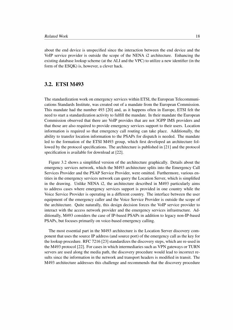
The standardization work on emergency services within ETSI, the European Telecommuni-cations Standards Institute, was created out of a mandate from the European Commission.This mandate had the number 493 [20] and, as it happens often in Europe, ETSI felt theneed to start a standardization activity to fulfill the mandate. In their mandate the EuropeanCommission observed that there are VoIP provides that are not 3GPP IMS providers andthat those are also required to provide emergency services support to their users. Locationinformation is required so that emergency call routing can take place. Additionally, theability to transfer location information to the PSAPs for dispatch is needed. The mandateled to the formation of the ETSI M493 group, which first developed an architecture fol-lowed by the protocol specifications. The architecture is published in [21] and the protocolspecification is available for download at [22].
Figure 3.2 shows a simplified version of the architecture graphically. Details about theemergency services network, which the M493 architecture splits into the Emergency CallServices Provider and the PSAP Service Provider, were omitted. Furthermore, various en-tities in the emergency services network can query the Location Server, which is simplifiedin the drawing. Unlike NENA i2, the architecture described in M493 particularly aimsto address cases where emergency services support is provided in one country while theVoice Service Provider is operating in a different country. The interface between the userequipment of the emergency caller and the Voice Service Provider is outside the scope ofthe architecture. Quite naturally, this design decision forces the VoIP service provider tointeract with the access network provider and the emergency services infrastructure. Ad-ditionally, M493 considers the case of IP-based PSAPs in addition to legacy non-IP-basedPSAPs, but focuses primarily on voice-based emergency calling.
The most essential part in the M493 architecture is the Location Server discovery com-ponent that uses the source IP address (and source port) of the emergency call as the key forthe lookup procedure. RFC 7216 [23] standardizes the discovery steps, which are re-used inthe M493 protocol [22]. For cases in which intermediaries such as VPN gateways or TURNservers are used along the media path, the discovery procedure would lead to incorrect re-sults since the information in the network and transport headers is modified in transit. TheM493 architecture addresses this challenge and recommends that the discovery procedure
19 3.2. ETSI M493
Access Network Provider
Emergency Call Services Provider &
PSAP Service Provider
Voice Service Provider
User
Agent
Location
Server (LS)
Emergency Call
Location Server
Discovery
Legend:
Voice Traffic
Signaling messages
Emergency Services
Routing Function
(ESRF)
Em
erg
ency
Call
SIP INVITE
PSAP
Figure 3.2.: M493 Architecture (Simplified)
be applied in a nested (or chained) fashion. For more details see Appendix A of [21].
Once the Location Server has been discovered the Voice Service Provider uses the HTTP-Enabled Location Delivery (HELD) [24–27] protocol or the Diameter protocol [28] to inter-act with the Location Server. HELD was initially designed to obtain location information,by value or by reference, but was later extended to also return emergency services callrouting information [27].
According to the M493 specification, HELD shall be used when no pre-established rela-tionship exists between the Voice Service Provider and the Access Network Provider. Whena pre-established relationship exists then the M493 specification allows Diameter, as spec-ified in ETSI ES 283 035 [29], to be used as an alternative solution. Civic and geospatiallocation information is conveyed as defined in IETF RFC 4776 [30], IETF RFC 3825 [31],or as a Presence Information Data Format Location Object (PIDF-LO) defined in IETF RFC4119 [6].

Related Work 20
3.3. DNS-SOS
With the DNS-SOS proposals [32] Brian Rosen (Neustar) suggested to using a DNS-basedmechanism to lookup emergency calling URIs and related emergency information. Theproposal assumes a new root, sos.arpa, to be maintained by an international organizationthat then uses country-level agencies to manage the next-lower level in the hierarchy. Forexample, at.sos.arpa would be maintained by an Austrian agency, which can then makefurther delegations for individual states, and cities, if necessary.
DNS-SOS makes use of the Dynamic Delegation Discovery System (DDDS) frame-work [33], which is a generic mechanism for storing application data in the DNS. Thisrequires a client-side algorithm for transforming a string into a domain name, which is sub-sequently resolved by the DNS to retrieve Naming Authority Pointer (NAPTR) ResourceRecord records [33–36]. In this proposal the input is location information, which is thentransformed into a so-called Application Unique String. This solution, as RFC 6950 [37]explains, allows the resolution of identifiers, such as telephone numbers or location infor-mation, that do not have a recognizable domain component to be treated as domain namesfor use with the DNS.
A NAPTR record contains the following structures:
• two different weighting mechanisms (”order” and ”preference”),• a ”service” field (such as ’sos+police’) to express the application the NAPTR record de-
scribes,• a ”replacement” field or a ”regular expression” field, which performs the translation.
Examples of NAPTR records can be seen in Figure 3.3.
The labels of the Application Unique String follow the civic location structure definedin [30, 38, 39]. This means that the string is expressed as a series of concatenated civiclocation tokens whereby tokens are separated by a period. For example, the applicationunique string ’innsbruck.tirol.at.sos.arpa’ indicates that the encoded civic address is in thecity of “Innsbruck”, in the state of “Tirol”, and in the country of “Austria”. The exactcanonicalization algorithm is not provided in the proposal. To take spelling variations intoaccount Brian Rosen including alternative spellings in databases as well. When certain civictokens from the hierarchy must be omitted, they would be expressed by the ’.null’ value.
To form an Application Unique String using geodetic location information the proposalsuggests to express latitude, longitude, and altitude by concatenating these three values sep-arated with a period. For example, 101d221.93d0345.0.geo.sos.arpa would be a geodetic

21 3.3. DNS-SOS
location with 101.221 degrees latitude, 93.0354 degrees longitude, and no altitude informa-tion6.
In addition to returning service URIs, the DNS-SOS proposal also envisions the followingmetadata to be provided via NAPTR records:
• a URI to a document containing PSAP URIs and service boundaries (in the form of poly-gons),
• a URI to a document containing subdomains. The aim of providing this information isfor searching, and
• a URI to a document containing building information. This information is meant to beused by first responders rather than for emergency call routing purposes and may requireconfidentiality protection and access control.
Using the subdomains in combination with the service boundaries would allow a DNSserver to respond to queries that include geodetic location information since the server cancollect the necessary information to use a point-in-polygon operation to determine whichPSAP to route the call to. However, the currently deployed DNS infrastructure does notprovide such functionality.
A more complete example of a fictional DNS configuration is shown in Figure 3.3. Theexample has been taken from Section 6.2 of [41] and modified to illustrate the differentservice types.
In response to the DNS-SOS proposal and related ideas to enhance the DNS with newfunctionality, the Internet Architecture Board (IAB) published RFC 6950 [37] to discuss thearchitectural consequences of using the DNS to implement application features. Engineerslike to reuse the DNS infrastructure due to its widespread deployment.
However, the DNS may not be a suitable infrastructure for some applications, as pointedout in RFC 6950. In the context of this proposal, the rules for processing requests of regularDNS queries where a hostname is resolved to an IP address are quite different than theresolution necessary to resolve location information together with a service identificationto a PSAP URI. In particular, the use of geodetic location information requires complexlocation-matching procedures, which the deployed DNS infrastructure does not offer.
6The example has been taken from Section 10 of [32]. Note that the recommendations in Section 5.2.1 ofRFC 5491 [40] either require the coordinate reference system (CRS) WGS 84 to be used, or to at least indicatea coordinate reference system.

Related Work 22
at.sos.arpa. PTR tirol.at.sos.arpa.
at.sos.arpa. PTR wien.at.sos.arpa.
us.sos.arpa. PTR salzburg.at.sos.arpa.
...
us.sos.arpa. PTR vorarlberg.at.sos.arpa.
tirol.at.sos.arpa. PTR innsbruck.tirol.at.sos.arpa.
tirol.at.sos.arpa. PTR hall.tirol.at.sos.arpa.
tirol.at.sos.arpa. PTR thaur.nj.us.sos.arpa.
...
tirol.at.sos.arpa. PTR rum.tirol.at.sos.arpa.
innsbruck.tirol.at.sos.arpa IN NAPTR
NAPTR 100 10 "u" "sos+fire"
"/.*/sips:[email protected]".
NAPTR 100 10 "u" "sos+police"
"/.*/sips:[email protected]".
NAPTR 100 10 "u" "sos+mountain"
"/.*/sips:[email protected]".
NAPTR 100 10 "u" "sos+rescue"
"/.*/sips:[email protected]".
NAPTR 100 10 "u" "sos+PSAP"
"/.*/sips:[email protected]".
...
Figure 3.3.: Example DNS-SOS Configuration.
3.4. 3GPP IMS
The IP Multimedia Subsystem (IMS) is an architecture that has been developed by the 3GPPto replace the circuit switched voice infrastructure and has been heavily influenced by itsprimary customers, i.e., telecommunication operators. The important design decision in theIMS architecture is that the Application Service Provider (ASP) and the Access NetworkProvider (ANP)7 are operated by the same entity. This design decision simplified the lo-
7The term ‘Application Service Provider’ (ASP) is defined in RFC 5012 [5] and the term ‘Access NetworkProvider’ (ANP) is defined in RFC 5687 [13]. The ANP is a combination of ‘Internet Access Provider’ (IAP)and ‘Internet Service Provider (ISP)’, two additional terms defined in RFC 5012 [5]. Note that in some countriesthere may be a split between the ISP and the IAP, but this separation is not relevant for the description of theIMS emergency services architecture.

23 3.4. 3GPP IMS
cation retrieval and emergency call routing procedure because they happen locally withinthe visited network. The designers of the IMS architecture also wanted to offer quality ofservice (QoS) mechanisms for emergency services, as explained in Section 3.6 of [19]. De-signing a QoS solution that operates locally is deployable when the application functionalityis offered by the network operator.
Gaining access to most networks requires successful completion of the network accessauthentication procedures. Extra steps had to be added to accommodate cases where theend device8 either has no credentials to authenticate to the network or is otherwise notable to perform a successful network access authentication (for example, when there are noroaming agreements or the subscription is not valid).
Figure 3.4 shows a simplified version of the architecture graphically. The main entities inthis diagrams are SIP entities, such as the various forms of Call Session Control Functions(CSCFs). CSCFs are SIP servers or proxies. The Emergency Call Session Control Func-tion (E-CSCF) is an entity introduced to provide emergency call handling functionality. Itinteracts with the Location Retrieval Function (LRF) and communicates with the PSAP inthe emergency services network either directly for IP-enabled PSAPs or indirectly via theBorder Gateway Control Function (BGCF) and a Media Gateway (MGW) in the case oflegacy PSAPs, and focuses on voice- and multi-media signaling exchanges using SIP withthe UE detecting the emergency call. The figure does not describe the underlying radio andnetwork attachment procedures. The IMS specifications distinguish the case where the UEis roaming, as shown in Figure 3.4, whereas it is not. In the roaming case, the emergencycall is not routed to the home network but instead processed locally via the E-CSCF inwhat is called a “local breakout”. In the roaming case an emergency registration is typicallyused (unless, for example, it is lacking credentials). The Serving CSCF (S-CSCF), which islocated in the home network, is contacted during emergency registration. The Interrogating-CSCF (I-CSCF) is at the edge of the administrative domain and relays communication tothe S-CSCF. Non-emergency calls are home routed, and emergency call handling thereforepresents an exception in the IMS architecture. Emergency registration uses the “sos” ser-vice URN [42] and ensures that a PSAP can initiate a callback, though the PSAP callbackitself is not shown in the figure. The Proxy CSCF (P-CSCF), which is the first point ofcontact for an IMS terminal, must also be provisioned with emergency service URNs andemergency numbers to detect an emergency call from the IMS terminal so that the E-CSCFcan be selected and call setups forwarded to it. After the SIP call establishment is complete,voice communication can be initiated, and as shown in Figure 3.4 a gateway may be usedto translate the call to the PSTN.
8The 3GPP uses the terms ‘User Equipment’ (UE) for a mobile IMS phone with a (U)SIM and ‘MobileEquipment’ (ME) for a phone without a (U)SIM and therefore no subscription.

Related Work 24
Home Network
Visited Network
Emergency Services Network
IMS
Terminal
P-CSCF
Legend:
Voice Traffic
Signaling messages
E-CSCF
PSAP
LRFI-CSCF
BGCF
&
MGW
SIP Register (“SOS”)
S-CSCF
SIP Register (“SOS”)PSAP URI
(+Location Info)
Emergency
Location
Request
SIP
INV
ITE
Emergency Call
Em
erg
ency C
all
SIP
INV
ITE
Em
erg
ency C
all
Figure 3.4.: IMS Architecture (Simplified)

Chapter4Comparison
The requirements outlined in Chapter 2 lead to the development of the IETF emergencyservices architecture and the design of the LoST protocol, as described in Chapter 5. In thischapter a comparison between the IETF emergency services architecture and the alternativesi.e. NENA i2, ETSI M493, DNS-SOS, and 3GPP IMS, is provided.
4.1. NENA i2
NENA i2 is an early transition solution and lacks many of the features later demanded.
International applicability: NENA i2 was designed specifically for the United Stateswith applicability to Canada. Architecture focused on fixed and nomadic use of VoIP andon the interworking with legacy PSAPs only.
Distributed administration: Route determination is provided by the VoIP PositioningCenter (VPC), which interfaces the Emergency Services Zone Routing Data Base (ERDB)and the Location Information Server (LIS).
Multi-mode communication: Focus of the architecture is on voice, particularly regard-ing the interworking with legacy PSAPs. Hence, there is no support for multi-modecommunication.
Anonymous mapping: The VPC uses the caller’s location as input to the route deter-mination process. It does not need the caller’s identity but the VSP provides customerinformation to the VPC in order to make it available to the PSAP. Therefore, no anony-mous mapping is provided.
Incrementally deployable: The architecture is meant to be deployable in selected coun-tries. It does, however, require the end devices to support the interaction with a LIS to

Comparison 26
obtain location information by value or by reference. Without this location support thedescribed architecture cannot be deployed incrementally even within a single country.
Anywhere mapping: Although not explicitly stated, the VPC is likely to interact onlywith authorized VSPs. Furthermore, the ERDB is only accessible by the VPC. As such,the VPC/ERDB are not able to provide mapping information in response to an individualquery from any location.
PSAP callback: NENA i2 provides PSAP callback support based on the callback numberstored by the VSP although without the security properties described in RFC 7090 [7].
Emergency calls from unauthenticated and unauthorized devices: NENA i2 doesnot support emergency calls from unauthenticated and unauthorized devices.
Vehicle-initiated emergency calling support: NENA i2 does not discuss Vehicle-initiated emergency calling.
Data-Only emergency calls: NENA i2 does not discuss data-only emergency calls.
4.2. ETSI M493
ETSI M493 has been developed long after NENA i2 and takes advantage of some of themore advanced IETF standardization work. The architecture also takes deployments intoaccount where the VSP is not offering IMS-based services. The focus on network operatorsoffering both location information and route determination is a strong requirement.
International applicability: ETSI M493 was the result of a mandate by the EuropeanCommission and applicability is within the EU member states. It considers legacy PSAPsas well as IP-based PSAPs.
Distributed administration: Access network providers and Emergency Call ServiceProviders have to closely cooperate in a single country since location and route deter-mination is provided by the access network providers.
Multi-mode communication: Focus of the architecture is on voice, but video and textsupport is also mentioned.
Anonymous mapping: The LS does not require caller information to perform a map-ping. As such, anonymous mappings are provided.
Incrementally deployable: The architecture requires a strong cooperation betweenVSPs and access network providers since the VSP has to determine the correct LocationServer (LS) based on information in the network layer (in most cases the IP address).There is no dependency on the end device in this architecture, at least conceptually.
Anywhere mapping: The LS can only provide mapping information in response to anquery from an emergency caller of the access network provider that operates the LS.

27 4.3. DNS-SOS
ETSI M493 anticipates that a LS may interact with other LSs, for example in case ofVPN scenarios. Whether this concept indeed works in practice is unknown.
PSAP callback: Details about PSAP callback are not described.Emergency calls from unauthenticated and unauthorized devices: ETSI M493
does not support emergency calls from unauthenticated and unauthorized devices.Vehicle-initiated emergency calling support: ETSI M493 does not discuss Vehicle-
initiated emergency calling.Data-Only emergency calls: ETSI M493 does not discuss data-only emergency calls.
4.3. DNS-SOS
DNS-SOS was an early attempt to untangle location determination from route determinationin a way that it can be deployed internationally. Re-using the DNS infrastructure was cleverbut also revealed a number of problems. Since the proposal was discontinued in favor ofLoST only a sub-set of the features are summarized below.
International applicability: DNS-SOS was meant to be used internationally, similarlyto the DNS.
Distributed administration: DNS-SOS allows distributed administration. For geodeticlocation information the proposal was underspecified and prevented the use of the regularDNS infrastructure due to the new search and matching procedure. The single root ofthe DNS infrastructure may, however, make deployments in certain regions more difficult(particularly when there is a dispute over a geographical region).
Anonymous mapping: DNS-SOS allows anonymous mapping.Incrementally deployable: DNS-SOS is incrementally deployable and the civic map-
ping is certainly easier to deploy even though new DNS infrastructure elements are re-quired. At the time when the DNS-SOS proposal was made the DNS offered very fewsecurity mechanisms, which may have negatively impacted its deployment (as it was seenwith other DNS extensions).
Anywhere mapping: It was envisioned that DNS-SOS allows mapping from anywhere.
4.4. 3GPP IMS
The 3GPP IMS emergency services architecture is an advanced IP-based communicationsystem developed for network operators who are also offering voice over IP services. As

Comparison 28
such, the classical telecommunication operators are the main audience for an IMS-basedsystem.
International applicability: The 3GPP IMS is applicable to IMS-based systems only. Itis internationally applicable once network operators in all countries deploy IMS. In themeanwhile those devices will fall back to PSTN-based emergency calling. Non-IMS-based service providers are excluded from emergency services support.
Distributed administration: The assumption of the IMS architecture is that the Appli-cation Service Provider (ASP) and the Access Network Provider (ANP) are operated bya single company, or are in close relationship. As such, route and location determinationis accomplished by the same entity.
Multi-mode communication: IMS aims to support voice, video and text.Anonymous mapping: Anonymous mappings are possible when the emergency callerhas not been authenticated by the network. In all other cases the involved IMS entitieshave information about the calling party.
Incrementally deployable: With the legacy emergency call support the 3GPP IMS ar-chitecture is incrementally deployable. Support for IMS does, however, require supportfrom the network
Anywhere mapping: In IMS an emergency caller can only expect route determinationprovided by the IMS entities in the access network. As such, there is no need for amapping to be provided by a non-local entity.
PSAP callback: Functionality for PSAP callback is provided.Emergency calls from unauthenticated and unauthorized devices: Emergencycalls from unauthenticated and unauthorized devices is supported.
Vehicle-initiated emergency calling support: Vehicle-initiated emergency calls aresupported.
Data-Only emergency calls: Data-only emergency calls are supported theoretically butare not described.
Table 4.1 compares NENA i2, ETSI M493, 3GPP IMS and the IETF emergency servicesarchitectures against each other. As it can be seen, the IETF emergency services architec-ture using LoST is the most versatile architecture and various emergency services featuresdeveloped for the IETF architecture have subsequently been re-used in other architecturesas well.

294.4.
3GPP
IMS
Feature NENA i2 ETSI M493 3GPP IMS IETFInternational applicability N P F FDistributed administration N P P FMulti-mode communication N P F FAnonymous mapping N F P FAnymous location N F P FIncrementally deployable N P F FAnywhere mapping N P N FPSAP callback P ND F FEmergency calls from unauthenticated and unauthorized devices ND ND F FVehicle-initiated emergency calling support ND ND F FData-Only emergency calls ND ND ND FSignaling security ND ND F FMedia security ND ND F FSupport for non-IMS end devices F F N FSupport for non-SIP end devices F F F F
Table 4.1.: Emergency Services Architecture Solution Comparison.
Legend:
Fully supported (F)Partially supported (P)
Not supported (N)Not described (ND)


Chapter5An IP-based Emergency ServicesArchitecture
Figure 5.1 shows the vision of an IP-enabled emergency services architecture graphically.The left side of the picture shows end devices attached to different access networks andcommunication service providers. In the Internet many applications are provided by com-panies independent from the access network operator and therefore the separation betweenthe access network and the communication service provider is indicated explicitly whereasin the circuit switched telephony world the application functionality was provided by the ac-cess network operator. The right side of Figure 5.1 depicts the IP-based emergency servicesnetwork. The developed technical specifications focus on both sides and use the Session Ini-tiation Protocol (SIP). While other protocols have been developed in the meanwhile, such asXMPP, RTCWeb, and many proprietary protocols, they have never received the same atten-tion from the emergency services community. Consequently, emergency services standardsare primarily available for SIP-based deployments.
In addition to phones, which have typically been used to place emergency calls, otherdevices have been used to communicate information relevant for emergency calls, includingInternet of Things devices that offer sensor data (such as smoke detectors), audio and videoinformation. The ability of placing emergency calls by vehicles has also extended the abilityto summon help faster and to provide more detailed information about the incident to thecall taker and first responders.
By design, these non-SIP-based communication architectures can, however, also be sup-ported and Figure 5.1 just refers to them as originating networks. Three core features mustbe provided by these originating networks in order to interwork smoothly with the standard-ized IP-based emergency services infrastructure:

An IP-based Emergency Services Architecture 32
Figure 5.1.: Communication Architecture Overviewa.
aCourtesy of Guy Caron, ENP
1. Ability to identify an emergency call.2. Ability to communicate location and/or a location reference.3. Ability to convey multi-media content.
These three core building blocks are described in more detail in Section 5.1. Some of thecommunication architectures in use today provide support for this functionality, such as the3GPP IMS architecture9, and the IETF SIP architecture. At the time of writing, there areother communication architectures that do not yet support emergency services, such as theReal-Time Communication in WEB-browsers [43] and the Extensible Messaging and Pres-ence Protocol (XMPP) [44]. There are also many non-standardized and proprietary com-munication architectures, such as Skype R©, and many smart phone messaging apps (such asWhatsApp).
Although it seems counterproductive to have many different communication architec-tures the reason for their existence is manifold. The history and background of the personsdesigning the different communication architectures often had a huge influence on the out-come. In many cases business models dictate design decisions of the work in differentstandards developing organizations. The following paragraph describes one such design
9The 3GPP IMS architecture uses the SIP protocol family as a foundation and is a variant of the moregeneric IETF SIP architecture.

33
differentiator.
The Internet architecture follows a layered design, which is a common design patternfor communication systems in general, and allows the replacement of different components(such as one radio technology with another one) while only impacting the neighboring lay-ers. In student textbooks, the Internet architecture has the data link layer, network layer,transport layer, and the applications layer. In the real world, the layering is much morecomplex, and it is sometimes hard to assign specific protocols to specific layers since pro-tocols can be used in a very flexible way and are often tunneled inside other protocols.The responsibility of providing implementations and deployments of certain layers is alsodistributed to different parties. In many deployments, the provider of physical connectivity(e.g., a wire or radio base stations) and the provider offering Internet connectivity are differ-ent companies. Furthermore, those companies offering Internet connectivity are very oftendifferent from those offering application layer services. This separation of functionality isa consequence of the end-to-end principle rather than the layering alone. The end-to-endprinciple states that end-to-end functions can best be realized by end-to-end protocols [45].While the end-to-end principle still leaves room for discussion and interpretation, many ap-plication deployments today happen independently of Internet connectivity deployments.Those who provide Internet connectivity would like to provide applications as well, or atleast benefit from the deployment of the applications. Consequently, a design that assumesthat the Internet access provider also offers application services is different from a designthat assumes a separation between the two parties. Such fundamental design assumptionslead to different communication architectures and consequently also to different designs forthe emergency services system even though it is possible to re-use the same building blocks.
The differences between XMPP-based, Skype R©-based, over-the-top SIP-based VoIP de-ployments, and RTCWeb are, on the other hand, less dramatic. All three assume indepen-dence of the application service provider from the Internet access provider. The differencesare mainly in the protocol choice. SIP is an IETF standard and is widely used for voicetraffic. Skype R© software, on the other hand, uses a proprietary protocol that only relies onSIP for interconnecting with other non-Skype R©-based systems. XMPP is also an IETF pro-tocol that has found widespread usage for instant messaging. RTCWeb is the most recentstandardization development that has been done by the IETF together with the W3C andre-uses Web development programming paradigms that rely on JavaScript and JavaScriptAPIs. For a discussion about the power of downloadable code, as provided by the Webarchitecture, read [46].
The term smart phone app just refers to an implementation of some protocol. It does notindicate whether a standardized or a proprietary protocol has been implemented. As such,a smart phone app may be an implementation of any of the protocols listed above, suchas a SIP-based VoIP client. In many cases, however, smart phone apps contain proprietary
An IP-based Emergency Services Architecture 34
communication protocol implementations.
5.1. Building Blocks
Recognizing Emergency Calls
In the early days of PSTN-based emergency calling, callers would dial a local number forthe fire or police department. It was recognized in the 1960s that trying to find this numberin an emergency caused unacceptable delays. Thus, most countries have been introducingsingle nationwide emergency numbers, such as 9-1-1 in North America and 1-1-2 in allcountries of the European Union. This became even more important as mobile devicesstarted to replace landline phones. As it can be seen from the introduction of 1-1-2 inEurope this education effort takes many years and the old emergency numbers are thereforestill in use today (in addition the European-wide 1-1-2 number).
In many countries, different types of emergency services, such as police or mountainrescue, are still identified by separate numbers. Unfortunately, there are more than 60 dif-ferent emergency numbers in use worldwide, many of which also have non-emergency usesin other countries, so that simply storing the list of numbers in all devices is not feasible.Furthermore, hotels, university campuses, and larger enterprises often use dial prefixes, sothat an emergency caller has to dial 0-1-1-2 to reach the fire department when making a callfrom a landline phone on premise.
With the introduction of smart phones new user interface designs emerged as well. Somedevices may use dedicated emergency calling buttons or similar user interface elements toinitiate an emergency call. Such mechanisms need to be carefully designed so that they arenot accidentally triggered, e.g., when the device is in a pocket.
Instead of conveying the actual dial string in a protocol message once the user has enteredit, a symbolic representation is used instead. This allows unambiguous emergency call iden-tification and automatic treatment of calls by VoIP call handling software. The mechanismused for this emergency call marking uses the Uniform Resource Names (URNs) defined inRFC 5031 [42], such as urn:service.sos.
Obtaining and Conveying Location Information
Location information is needed by emergency services for three reasons: routing thecall to a PSAP that is closest to the emergency caller, dispatching first responders (e.g.,policemen or ambulance) to the location of the emergency, and determining the emergency

35 5.1. Building Blocks
service dial strings that are supported in a specific area. It is obvious that location hasto be determined automatically for the first and third purpose. Experience has shown thatautomated, highly accurate location information is vital to dispatching as well, rather thanrelying on the caller to report his or her location to the call taker. This increases accuracyand avoids dispatch delays when the caller is unable to provide location information due tolanguage barriers, lack of familiarity with his or her surroundings, stress, physical or mentalimpairment. For this reason, automatic location determination and location conveyance foremergency calls are important requirements in nearly all countries.
Location information for emergency purposes comes in two representations: (a) geospa-tial (or also called geodetic), e.g., longitude and latitude, and (b) civic, e.g., street addressessimilar to postal addresses. For indoor location vertical information (floor level) is very use-ful. Civic locations are utilized for fixed Internet access, including wireless hot spots, andare often preferable for specifying indoor locations in complex buildings, while geodeticlocation is frequently used for mobile devices, such as cell phones. However, with the in-troduction of femto and pico cells civic location is feasible with mobile phones and accurategeodetic information can be very hard to acquire indoors.
The requirements for location accuracy differ between routing and dispatch. For callrouting, city or even county-level accuracy is often enough, depending on how large thePSAP service areas are, while first responders benefit greatly when they can pinpoint thecaller to a building or, better yet, apartment or office for indoor locations, and an outdoorarea of at most a few hundred meters outdoors. This avoids having to search multiplebuildings, e.g., for medical emergencies.
Various protocol mechanisms have been developed to obtain location information fromLocation Servers. Devices without GPS may interact with these Location Servers and in cer-tain cases even devices with GPS receivers may contact Location Servers to obtain verifiedlocation information or for obtaining GPS-based location information faster using server-provided assistence data. Chapter 5 discusses various location protocols that have beendeveloped to allow the calling device, the PSAP, or some other proxy on behalf of them torequest location information.
Routing Emergency Calls
Once an emergency call is recognized, the call needs to be routed to the appropriatePSAP. Each PSAP is only responsible for a limited geographic region, its service region.In addition to the geographical region different PSAPs often only provide their service forspecific services, such as police, fire, ambulance, etc. There is a wide range of different de-ployment models used throughout the world and a description of the different PSAP modelsfor Europe can be found in [47, 48].

An IP-based Emergency Services Architecture 36
The number of PSAPs serving a country varies quite a bit. Sweden, for example, has 18PSAPs and the United States approximately 6,200 (at the time of writing). Therefore, thereis roughly one PSAP per 500.000 inhabitants in Sweden and one per 50.000 in the US. Asall-IP infrastructure is rolled out, smaller PSAPs may be consolidated into regional PSAPs.
Emergency calls are primarily routed based on the emergency caller’s location informa-tion. Routing may also take place in multiple stages taking factors, such as the number ofavailable call takers, the load situation of a PSAP, supported media (such as voice, real-timetext), or the language capabilities of the call takers into account. It is expected that theimportance of dynamic call routing will increase in the near future. In order to perform theinitial location-based routing step to get the call setup messages to an entity closer to thePSAP, information about the service boundaries of PSAPs need to be known to end devices,to VSPs or to other call routing entities. This information must somehow be shared. Today,Excel sheets are used [49] to exchange phone numbers associated with PSAP service bound-aries. A call taker then must analyze the situation, lookup the appropriate phone number,and manually re-route the call. This may be a reasonable initial step for the small number oftransnational emergency calls that are misrouted in today’s emergency services system butis not a future-proof approach for a next generation IP-based emergency services system.The inability of emergency centers to quickly re-route calls due to an overload situation ina mass incident has already been recognized [50].
5.2. Routing Emergency Calls
In limited scenarios, where the VSP and the ISP role are offered by the same provider rout-ing of IP-based emergency calls can be based on statically pre-configured rules. However,the separation of these two roles to separate companies introduces challenges for emer-gency call routing. In addition, emergency services authorities are interested to use IP andSIP-based functionality to route calls more dynamically. To decouple the routing enforce-ment point from the decision point an automated procedure has been standardized. Twomechanisms are available: the service boundary exchange mechanism [51] and the Loca-tion to Service Translation (LoST) protocol [52]. LoST may make use of LoST Sync fordistributing mappings between trusted distribution points for efficiency purposes. LoST, asillustrated in Figure 5.2, is an HTTP-based query/response protocol where a client sendsa request containing the location information and service URN to a server and receives aresponse, containing the service URL, typically a SIP URL, the service region where thesame information would be returned and an indication of how long the information is valid.Both request and response are formatted as XML. For efficiency, responses are cached. Theresponse may also indicate that only a more generic emergency service is offered for thisregion. For example, a request for ’urn:service:sos.marine’ in Austria may be replaced by

37 5.3. Obligations
Location Information+
Service URN
Emergency Number+
Service URN+
(PSAP) URI+
Service Boundary
L o S T
Figure 5.2.: High-Level Functionality of Location-to-Service Translation (LoST).
Figure 5.3.: Main Components involved in an Emergency Call.
’urn:service:sos’. Finally, the response also indicates the emergency number / dial string forthe respective service.
5.3. Obligations
In this section we discuss the requirements the different entities need to satisfy, based onFigure 5.3. A more detailed description can be found in [15]. Note that this narrationfocuses on the final stage of deployment and does not discuss the transition architecture,in which some implementation responsibilities can be re-arranged, with an impact on theoverall functionality offered by the emergency services architecture. A few variations wereintroduced to handle the transition from the current system to a fully developed ECRITarchitecture.

An IP-based Emergency Services Architecture 38
With the work on the IETF emergency architecture we have tried to balance the respon-sibilities among the participants, as described below.
5.3.1. End Hosts
An end host, through its VoIP application, has three main responsibilities: it has to attemptto obtain its own location, determine the URI of the appropriate PSAP for that location, andrecognize when the user places an emergency call by examining the dial string. The endhost operating system may assist in determining the device location.
The protocol interaction for location configuration is indicated as interface (a) in Fig-ure 5.3 and several location configuration protocols have been developed to provide thiscapability. Note that end hosts may also obtain location information via GPS.
A VoIP application needs to support the Location-to-Service Translation (LoST) pro-tocol [52] in order to determine the emergency service dial strings and the PSAP URI.Additionally, the service URNs, defined in [42], need to be understood by the device.
As currently defined, it is assumed that PSAPs can be reached by SIP, but may supportother signaling protocols, either directly or through a protocol translation gateway. A LoSTresponse indicates whether other signaling protocols are supported. To provide support formulti-media communication different types of codecs may need to be supported or dynam-ically negotiated, whereby the details can be found in [15].
5.3.2. ISP
The ISP has to make location information available to the end point via one or more of thelocation configuration protocols.
In order to route an emergency call correctly to a PSAP, an ISP may initially disclosethe approximate location for routing to the end point and more precise location informationlater, when emergency personnel is dispatched by the PSAP operator. The functionalityrequired by the IETF emergency services architecture is restricted to the disclosure of arelatively small amount of location information, as discussed in [14].
The ISP may also operate a caching LoST server to improve the robustness and the reli-ability of the architecture. This lowers the roundtrip time for contacting a LoST server, and

39 5.3. Obligations
the caches are most likely to hold the mappings of the area where the emergency caller iscurrently located.
In the case where ISPs allow Internet traffic to traverse their network, the signaling andmedia protocols used for emergency calls function without problems. Today, there areno legal requirements to offer prioritization of emergency calls over IP-based networks.While the standardization community has developed a range of Quality of Service signalingprotocols, their widespread deployment has not happened yet.
5.3.3. VSP
SIP does not mandate that call setup requests traverse SIP proxies, i.e., SIP messages can besent directly to the user agent. Thus, even for emergency services, it is possible to use SIPwithout the involvement of a VSP. However, in terms of deployment, it is highly likely thata VSP will be used. If a caller uses a VSP, this VSP often forces all calls, emergency andregular calls, to traverse an outbound proxy or a session border controller (SBC) operatedby the VSP. If some end devices are unable to perform a LoST lookup, the VSP can providethe necessary functions as a back-up solution.
If the VSP uses a signaling or media protocol that is not supported by the PSAP, it needsto translate signaling messages and potentially also media flows.
VSPs can assist the PSAP by providing identity assurance for emergency calls, e.g., usingSIP Identity (RFC 3325 [53]), thus helping to prosecute prank callers. However, the linkbetween the subscriber information and the real-world person making the call is often weak.In many cases, VSPs have, at best, only the credit card data for their customers and some ofthese customers may use gift cards or other anonymous means of payment.
5.3.4. PSAP
The emergency services best current practice specification [15] only discusses the stan-dardization of the interfaces from the VSP and ISP towards PSAPs and some parts of thePSAP-to-PSAP call transfer mechanisms that are necessary for emergency calls to be pro-cessed by the PSAP. Many aspects related to the internal communication within a PSAP,between PSAPs as well as between a PSAP and first responders are beyond the scope of theIETF specification.
When emergency calling has been fully converted to Internet protocols, PSAPs must ac-

An IP-based Emergency Services Architecture 40
cept calls from any VSP, as shown in interface (d) of Figure 5.2. Since calls may comefrom all sources, PSAPs must deploy mechanisms to reduce the number of malicious calls,particularly calls containing intentionally false location information. Assuring the relia-bility of location information remains challenging, particularly as more and more devicesare equipped with Global Navigation Satellite Systems (GNSS) receivers, such as GPS, al-lowing them to determine their own location [54]. However, it may be possible in somecases to verify the location information provided by an end host by comparing it againstnetwork-provided location information.
5.4. LoST Mapping Architecture
So far, we have described the LoST protocol as it is described in RFC 5222 [52], namelyas a client-server protocol. A single LoST server, however, does not store the mappingelements for all PSAPs worldwide, for both technical and administrative reasons. Thus,there is a need to let LoST servers interact with other LoST servers, each covering a spe-cific geographical region. The LoST protocol already provides the baseline mechanisms forsupporting such a communication architecture, as described in RFC 5582 [55], an infor-mational RFC providing terminology (in the form of different roles for LoST servers thatdistinguish their behavior) and explaining the basic concept of the LoST mapping architec-ture. RFC 5582 motivates the basic design decision for LoST to utilize it in a wide variety ofarchitectures, but leaves the detailed instantiation to deployments in different jurisdictions.
The awareness of peering LoST servers determines the structure of the architecture ratherthan certain physical properties of a network, such as the topology of a fiber installation,or the structure of a national emergency services organization. Two types of structuresare used in combination, namely a mesh and a hierarchical structure. The mesh topologyis envisioned for the top-level LoST entities, whereas the hierarchical structure reflects aparent - child relationship in a tree. Figure 5.4 shows this structure graphically with theLoST servers acting in their roles of forest guides (FGs) and trees. A tree consists of aself-contained hierarchy of authoritative mapping servers (AMS) for a service. An AMS isa LoST server that can provide the authoritative answer to a set of queries. The top-mostserver in a tree is called the tree root and this server peers with one or multiple FGs, i.e., thetree root announces its coverage region to other FGs. In Figure 5.4, for example, the root oftree 1 interacts with FG A and makes the coverage area available. FG A also receives thecoverage area from the root of tree 2. All tree roots receive information about the coveragearea of their children in the tree. On the top level, all FGs (namely FG A, FG B, and FG C)form a mesh and synchronize their coverage areas.
Seekers and resolvers are two additional LoST entities in the LoST mapping architecture

41 5.4. LoST Mapping Architecture
Figure 5.4.: Trees and Forest Guides in the LoST Mapping Architecture.
that are not shown in Figure 5.4. Neither seekers nor resolvers provide authoritative an-swers themselves but they may cache results. Caching of mapping elements by resolvers isexpected to be very common.
To best understand the LoST mapping architecture it is important to highlight the maindesign goals:
Robustness: To ensure the stability of the system it still needs to function even if dif-ferent deployment decisions in various parts of the world are made. It cannot be assumedthat everyone deploying LoST servers has to agree with everyone else. The minimumlevel of agreement that has to be ensured is that AMSs are able to authoritatively answermapping queries, i.e., only those LoST servers respond authoritatively if they indeed havethe authority of a specific coverage area.
Consistent Responses: Any device (called seeker) can issue a LoST query and it willget a consistent answer regardless of where the query enters the system. In some (rare)cases of territorial disputes, two AMSs may claim authoritative for the same region. Insuch a case, the answer received by a seeker will vary depending on the entry point intothe mapping system.
Scalability: Scalability of the LoST architecture is ensured by using caching and thedistributed nature of the LoST servers in the architecture. Any LoST entity may supportcaching of received mapping elements. The mapping elements may be obtained as part ofthe ordinary operation of LoST (via query and responses) but also via separate replicationof the mapping elements. LoST Sync [51] is one such protocol to exchange mappings

An IP-based Emergency Services Architecture 42
between LoST servers (and other entities).Minimal Seeker Configuration: A seeker is a LoST client requesting a mapping. Theonly information a seeker needs to know is the address of a resolver; it does not needto know the structure of all Forest Guides nor does it need to maintain a global pictureof LoST servers. To avoid having end user involvement in the configuration of LoSTservers, Section 4 of the LoST specification [52] provides a discovery technique basedon DNS, and RFC 5223 [56] offers a DHCP-based discovery procedure. Although LoSTservers can be located anywhere, a placement topologically closer to the end host, e.g.,in the access network, may be desirable in disaster situations with intermittent networkconnectivity. RFC 5223 offers this capability.
Even though it is technically possible to let seekers and resolvers enter their queries at anypoint in the LoST mapping architecture, a deployment choice is to configure resolvers withthe addresses of the FGs. A query and response for an emergency caller located in Germanywith a service provider in Finland could then be shown as depicted in Figure 5.5. In ourexample we assume that the VSP deploys a LoST resolver that is contacted by LoST seekers.We furthermore assume in this example that no caching takes place to illustrate the messageflow (as shown with dotted lines). In message (1) the seeker contacts its pre-configuredresolver with a recursive query providing its current location (somewhere in Germany). Theresolver does not have any information about the PSAP that must be contacted for the givenlocation in Germany (for the solicited service). Since the resolver knows the address of theFG (only one FG is shown in our example), it issues an iterative query to it, as marked withmessage (2). The FG responds with the entry point for the German LoST tree. The resolverthen issues another query towards the provided tree root in message (3). In this example,we assume that the root of tree 1 knows the address of the PSAP the seeker must contact.This final response is then forwarded to seeker via the resolver. The resolver would want tocache the intermediate and final results to speed-up later lookups for the same geographicalarea and the same service. Once the seeker knows the final answer, it can proceed withthe emergency call setup procedure to contact the PSAP, as shown in message (4) with thedouble line. (Note that the response for a different service may yield a somewhat differentservice boundary.)
As illustrated, LoST servers form a distributed mapping database, with each server car-rying mapping elements. These mapping elements are the main data structure that is com-municated in the LoST protocol, synchronized between FGs and LoST servers in the tree,and cached by resolvers and seekers. Figure 5.6 shows the data elements of this importantdata structure graphically.

43 5.4. LoST Mapping Architecture
Figure 5.5.: Example Query / Response in the LoST Mapping Architecture.
expires
lastUpdated
source
sourceId
displayName
service
uri
serviceNumber
serviceBoundary
Unique identification of a mapping element
Entity (e.g., PSAP or ESRP) the call has to be routed to
Dial string corresponding to the indicated service
Geographical area for whichall subsequent requests willlead to the same results
Lifetime of the mapping
Human readable description of the mapping
Service URN usedfor this mapping
Figure 5.6.: Mapping Element.
An IP-based Emergency Services Architecture 44
5.5. Steps towards an IETF Emergency Services Architecture
The architecture described so far requires changes both in already-deployed VoIP end sys-tems and in the existing PSAPs. The speed of transition and the path taken varies betweendifferent countries depending on funding and business incentives. As such, it is difficult toargue whether upgrading end points will be easier or replacing the emergency service infras-tructure. In any case, the transition approaches being investigated consider both directions.We can distinguish roughly four stages of transition:
• In the first stage VoIP end systems cannot place emergency calls at all.• In a second stage, VoIP callers manually configure their location, and emergency calls are
routed to the appropriate PSAP as circuit-switched calls via VoIP-PSTN gateways. Thislevel of service is offered in some countries for PSTN-replacement VoIP services, i.e.,VoIP services that are offered as replacement for the home phone. In the United States,this is known as the ”NENA i2” transition architecture.
• In a third stage, PSAPs maintain two separate infrastructures, one for calls arriving via anIP network, and another one for calls originating in the legacy infrastructure.
• In the final stage, all calls, including those from traditional cell phones and analog landlinephones, reach the PSAP via IP networks, with the legacy calls converted to IP-based calls,based on the requirements outlined in [57], either by the carriers or by gateways at theedge of the emergency service infrastructure.
5.5.1. Legacy End Points
Figure 5.6 shows an emergency services architecture with legacy end points. When theemergency caller dials the European-wide emergency number ’112’ (step 0), the devicetreats it as any other call without recognizing it as an emergency call, i.e., the dial stringprovided by the end point that may conform to RFC 4967 [58] or RFC 3966 [59] is signaledto the VSP (step 1). Recognition of the dial string is then left to the VSP for processing/sort-ing; the same is true for location retrieval (step 2) and routing to the nearest (or appropriate)PSAP (step 3). Dial string recognition, location determination and call routing are simpleron a fixed device and voice / application service provided only by the ISP than when theyare provided via separate a VSP and ISP.
If devices are used in environments without location services, the VSP’s SIP proxy mayneed to insert location information based on estimates or subscriber data. We briefly de-scribe these cases below.

45 5.5. Steps towards an IETF Emergency Services Architecture
Figure 5.7.: Emergency Services Architecture with Legacy End Points.
There are two main challenges to overcome when dealing with legacy devices: First, theVSP has to discover the LIS that knows the location of the IP-based end host. The VSPis only likely to know the IP address of that device, which is visible in the call signalingmessage that arrives at the VSP. When a LIS is discovered and contacted, and some amountof location information is available, then the second challenge arises, namely how to routethe emergency call to the appropriate PSAP. To accomplish the latter task, it is necessary tohave some information about the PSAP boundaries.
[15] does not describe a complete solution for interworking with legacy PSAPs but in-stead offers building blocks to use. The following constraints exist when dealing with legacyend points:
• Only the emergency numbers configured at the VSP are understood. This may lead tocases where a dialed emergency number is not recognized or a non-emergency call isrouted to a PSAP.
• Using the host’s IP address to discover the ISP network to which the host is attached ischallenging and may, in case of mobility protocols and VPNs, lead to wrong results.
• Security and privacy concerns may arise when many VSPs/ASPs can retrieve locationinformation from an ISP. It is likely that only authorized VSP/ASPs will be granted accessto location information for privacy, security and business reasons. Hence, it is unlikelythat such a solution would work smoothly across national boundaries.
• When the emergency call is not recognized by the User Agent then functions like callwaiting, call transfer, three-way call, flash hold, outbound call blocking, etc. cannot bedisabled. This may lead to unexpected user experience.
• The User Agent software may block callbacks from the PSAP since it does not have ways

An IP-based Emergency Services Architecture 46
to recognize incoming calls related to the earlier emergency.• Privacy settings may not be respected, and identity information may get disclosed to
unauthorized parties. These privacy features exist in some jurisdiction are even availablefor emergency calls.
• Certain VoIP call features may not be supported, such as a REFER (for conference calland transfer to secondary PSAP) or the Globally Routable User Agent URIs (GRUU) foridentifying individual devices issuing the emergency call.
• User Agents will not be able to convey location information to the VSP (even if it isavailable).
As discussed in Chapter 3 a LIS discovery mechanism has been standardized with RFC7216 [23] and HELD was extended in RFC 7840 [27] to also return emergency servicescall routing information. While this helps to tackle the main challenges it still leaves theinternational deployment questionable due to security and privacy concerns.
5.5.2. Partially Upgraded End Hosts
A giant step forward in simplifying the handling of IP-based emergency calls is to providethe end host with some information for LIS discovery. The end host may, for example, learnthe ISP’s domain name, by using LIS discovery [60], or might even obtain a Location byReference (LbyR) via HELD [24]. The VSP is then either able to resolve the LbyR in orderto route the call or to use the domain to discover a LIS using DNS. It is even possible toassociate policy information to the URI resolution procedure based on the extension definedin RFC 7199 [61]. The use of LbyRs together with this policy extension provides additionalprivacy features since location information is only disclosed to those parties in possession ofthe location reference and the end devices, as the target, can control the resolution processusing policies.
Additional software upgrades at the end device may allow emergency calls to be rec-ognized based on some pre-configured emergency numbers (e.g., ’1-1-2’ and ’9-1-1’) andallow for the implementation of other emergency service-related features, such as disablingsilence suppression during emergency calls.
5.5.3. Emergency Services for Persons with Disabilities
The capabilities of modern IP-based communication protocols, such as SIP, easily enablemulti-media communication. Video, real-time text, and instant messaging give persons with

47 5.5. Steps towards an IETF Emergency Services Architecture
disabilities access to emergency services. Unfortunately, support for multi-media commu-nication by emergency authorities is still poor, if available at all. Fax has been used inseveral countries in Europe, and Teletypewriter (TTY) in the US. In the meanwhile, moreand more countries are offering SMS-based access to emergency services for persons withdisabilities. The European REACH-112 pilot project [62] showed that the standardized IP-based emergency services technology is available and working. Proper integration of thetext messaging system into the PSAP software environment is, however, often not availableand additional training of call takers is necessary to ensure proper response times. Fromthe REACH-112 pilot and from various SMS-based emergency services deployments, it isknown that few persons make use of the new capabilities. This circumstance may havemany reasons, such as a lack of awareness of the availability of such a service, unfamiliaritywith multi-media emergency calls, and the smaller user base that needs such capabilities(compared to those who feel comfortable just making voice-based emergency calls).
The ability to use multi-media communication has significantly increased over the last10 years with the increasing capabilities of smart phones. Transmitting instant messages,real-time text, pictures, and video is a common feature of applications running on smartphones and Internet tablets. Since the deployment of IP-based phones is increasing dramat-ically, we expect that more users, not only those with disabilities, will find the multi-mediafunctionality attractive.
The use of IP-based protocols does not only offer additional functionality but also addsproperties like protocol feature and media type negotiation. This allows two communicationend points to agree on the latest and best possible communication mechanisms. This isclearly important for extensibility and incremental deployment. If, for example, a devicesupports a better and newer audio codec then this may lead to better audio quality witha lower bandwidth overhead. In addition to the support provided by SIP, LoST allowsemergency services authorities to publish information about the protocols through whichthey are reachable via information encoded in the URIs returned by the LoST protocol.
5.5.4. Vehicle Initiated Emergency Calls
A quick response by emergency services is essential to save lives in a car accident. When anemergency call is automatically triggered, and location information is provided along withthe emergency call then the number of road deaths and injuries can be reduced.
In the late 1990s the European Commission started an initiative to require car manufactur-ers to install a so-called in-vehicle system (IVS), which enables vehicle initiated emergencycalls. This system became known as eCall. The IVS is able to initiate an emergency call,

An IP-based Emergency Services Architecture 48
supports GPS-based location information and can obtain sensor data from the vehicle.
A circuit switched eCall system was standardized, which uses a regular voice call and aninband modem to communicate vehicle information, crash related sensor data, and locationinformation (the Minimum Set of Data or MSD) within the voice channel.
Deploying this circuit switched eCall system took a very long time, mostly due to politicalreasons. With the transition to IP-based networks it was an obvious step to also standardizethe next generation (NG) eCall system. NG-eCall moves from circuit switched to all-IP andcarries the vehicle data and crash information as additional data along with SIP signaling.
RFC 8147 [63] standardizes the NG-eCall functionality by re-using the already specifiedIP-based emergency services functionality. RFC 8147 defines the necessary MIME mediatypes for the MSD and a procedure for requesting and responding to further data requestsfrom the PSAP.
A new new Service URNs is defined in RFC 8147 to allow the routing of eCalls, bothmanually initiated as well as automatically triggered, to the correct PSAP. A test ServiceURN is also defined to allow the eCall system to be tested without negatively impacting anyongoing emergency calls.
A separate specification, RFC 8148 [9], specifies emergency calls placed by vehicles foruse in regions other than Europe, which make use of a different set of vehicle (crash) data,namely the Vehicle Emergency Data Set (VEDS) rather than the eCall Minimum Set ofData (MSD). In addition to the different data communicated to the PSAP three differentdeployment models are supported:
• In the ”direct model” the IVS communicates the emergency call and the crash data directlyto the PSAP.
• In the ”paired model” the IVS interacts with a handset, which then communicates theemergency call and the crash data to the PSAP.
• Finally, in the ”TSP model” the IVS interacts with a third party, the Telematics ServiceProvider (TSP), which then routes the emergency call and the crash data to the PSAP.
5.5.5. Additional Data
Call takers, first responders, and the emergency services community in general prefer tohave better situational awareness about an emergency related incident. More informationalone is, however, not sufficient it also needs to be of better quality. The importance of accu-

49 5.5. Steps towards an IETF Emergency Services Architecture
rate location information has already been highlighted and with emergency calls triggeredby vehicles additional information is available about the crash and the vehicle itself.
There are, however, various other sources of information. The originating device, theaccess network provider to which the device is connected, and all service providers in thepath of the call have information about the call, the caller, or the location, which is helpfulfor the PSAP to have in handling the emergency.
RFC 7852 [64] defines data structures and mechanisms to convey such data to the PSAPeither per-value or by reference. Conveying information by reference allows extra accesscontrol policies to be applied before releasing information. This can help to ensure betterprivacy protection since this additional data about the call, caller, and the location is datadirectly or indirectly related to a person.
5.5.6. Data-Only Emergency Calls
RFC 6443 [57] describes how IP-based emergency calls are initiated from devices usingSIP and how they are processed by PSAPs. The focus is thereby on multimedia calls, whichalmost always includes voice but may include real-time text, video and instant messaging.The ability to include additional data alongside the call has been highlighted previouslyalready.
In some cases devices do not need to establish a communication session to transmit voice,video and other multimedia. [10] focuses on the cases where the transmission of applica-tion data is all that is needed. To communicate sensor information the Common AlertingProtocol (CAP) is used inside a SIP MESSAGE. For communication security DTLS / TLSis re-used. CAP is known for authority-to-citizen early warning but can also be used in thereverse communication direction, namely from devices to the PSAP. CAP is an XML-baseddocument format with pre-defined information elements to communicate meta-data aboutthe alert and the sensor readings itself. For location information and other data the existingpayloads can be used in the SIP message offering seamless integration of sensors and otherInternet of Things devices into the emergency services infrastructure.
The data-only emergency call concept marked a transition from the classical voice (wherethe human was in the center of the communication) to a model where data is communicatedautomatically by machines. While this work is still at an early stage it represents a promis-ing direction for future research where automatic processing of many events combined withmachine learning may allow to detect dangerous situations quicker. Chapter 7 exploresoptions for securing data communication of IoT devices using standardized security tech-nologies.


Chapter6Securing IP-based Emergency ServicesNetworks
6.1. Introduction
IP networks and the SIP-based communication infrastructure creates the foundation on topof which emergency services support is added via a number of building blocks. The build-ing blocks provide the basis for (a) determining location information, (b) recognizing anemergency call, (c) evaluating the route towards the PSAP, (d) establishing the SIP sessionsetup and (e) exchanging multi-media data traffic (such as voice, video, text messages, andreal-time text). As explained in Chapter 5 there are architectural variants that impact whichof these building blocks are used and how. While there are unique aspects to each of thesearchitectural variants, many of the security aspects are still common across all IP-basedemergency services deployments.
When considering the security properties of the overall emergency services system, twoobservations can be made:
1. Emergency services support builds on top of the regular communication infrastructure,and therefore the security properties of the underlying infrastructure are inherited.
2. Security has to be taken into consideration for each and every protocol since the result-ing system is as secure as the weakest link. This also implies that the security analysisavailable for each protocol has to be taken into account by the respective users of thoseprotocols.
Developing protocol specifications by incorporating security during the design is onlythe first step in developing secure Internet-scale systems. Implementations of these pro-

Securing IP-based Emergency Services Networks 52
tocols also need to be secure against various attacks, such as buffer overflows, and thedeployed system must be configured in the appropriate way (e.g., to withstand denial of ser-vice attacks or to be secured against unauthorized access). Building secure communicationsystems that include emergency services components is complex and presumes educationand awareness (e.g., via employee training), good software management practices (e.g.,secure coding, extensive testing, software update processes), established and working pro-cesses (e.g., incident management, clearly defined responsibilities and accountability), etc.A detailed discussion of the secure software development lifecycle is, however, outside thescope of this thesis. Instead, the focus of this work is mainly on the initial phase of thelifecycle, namely on the protocol design. Building communication systems based on stan-dards provides better guarantees that specifications have been extensively reviewed therebyimproving the quality of the work.
To focus on the security characteristics that are unique to emergency services I first de-scribe the communication model, the involved entities, and then investigate the adversarymodel and the security threats. Finally, a list of countermeasures is provided.
6.2. Communication Model
The high-level communication models are shown in Figure 6.110.
As shown in Figure 6.1, there are four main communication interactions to consider:
I. SIP Signaling Communication: The SIP signaling exchange is at the heart of theIP-based emergency services communication and travels between the endpoints, the endhost and the PSAP. SIP [66] is an application-layer control (signaling) protocol for cre-ating, modifying, and terminating sessions with one or more participants. Emergencyservices functionality has been added to SIP with specifications that define the ability toexpress emergency services functionality (by using the service URN specification in RFC5031 [42]) and the ability to carry location objects (see [67]). SIP uses proxies as inter-mediaries to route the call. Due to the added emergency services functionality SIP roxies
10This chapter uses the terms ’Location Server’ (LS) as well as ’Location Information Server’ (LIS). RFC6280 [65] describes the LIS as follows: ”Some entities performing the Location Generator (LG) role are de-signed only to provide Targets with their own locations, as opposed to distributing a Target’s location to others.The process of providing a Target with its own location is known within Geopriv as Location Configuration.The term ’Location Information Server’ (LIS) is often used to describe the entity that performs this function.However, a LIS may also perform other functions, such as providing a Target’s location to other entities.” RFC6280 defines the Location Server as follows: “Location Server: The Location Server is responsible for enforcingthe Target’s Privacy Rules.”

53 6.2. Communication Model
Figure 6.1.: Communication Model Overview.
are also called Emergency Services Routing Proxies (ESRPs). The PSAP itself is locatedinisde the Emergency Services IP Network (ESINet). Chapter 5 describes the emergencyservices architecture as standardized by the IETF in more detail. After the emergency ser-vices communication is terminated, it is possible for the PSAP to initiate a callback to theemergency call, for example, when details about the situation need to be clarified or thecaller prematurely terminates the conversation. The call setup procedure then starts withthe PSAP and the SIP session setup messages travel towards the end device that initiatedthe call.
II. Exchange of Multi-Media Data: The main purpose of the communication setupis to exchange data. For emergency calls this typically takes the form of voice packets. Inthe future, this will also be video, instant messages, real-time text, and pictures, supportedby the capabilities of IP. SIP can detect and negotiate the supported functionality and toenable the exchange of these additional media streams. The used media will largely

Securing IP-based Emergency Services Networks 54
depend on the capabilities of the devices, the installed software applications, and thepreferences of the emergency caller. For persons with disabilities, real-time text andvideo communication is likely to make a big difference, but might require a third partyrelay service to be invoked, for example, for sign language interpretation.
III. Mapping Database: When emergency call setup is initiated, the call routing pro-cesses must decide the next hop to route the setup messages to. A major factor in callrouting is location information since the geographically closest PSAP will often want toreceive the call first. In some cases, other factors, such as the load situation at a PSAP orthe ability to accept certain media types, also influence the decision. For location-basedrouting, the distributed mapping database that uses the protocol LoST is used, as illus-trated in [55] and described in Chapter 5. The design allows end hosts and ESRPs to askfor the appropriate PSAP based on a given location input.
IV. Location Infrastructure: The location retrieval interaction starts with an entity is-suing a request for a location object. The requesting party is the Location Recipient,which may be the end host, an ESRP, or the PSAP. Each of these entities have a legit-imate interest in receiving location information for the determination of the appropriateemergency dial strings, for emergency call routing, or for the dispatch of first responders.When a location server, which is commonly assumed to be operated by an ISP, receivesa location request, it may not always have the current information cached. The locationserver then starts a location determination process whereby location generators collectpositioning data. The location server may provide location information not only as a one-shot transaction, or may provide multiple updates as location determination techniquescompute better location over time or when the location of the target device changes. Forsecurity and privacy purposes, location may not be shared without a prior authorizationcheck, which is invoked based on a rule set available to the location server. RFC 6280 [65]illustrates a location architecture and introduces terminology.
6.3. Adversary Models
In a discussion about security, it is important to keep the anticipated capabilities of an ad-versary in mind. We distinguish between three types of adversaries:
External Adversary Model: This type of adversary is the most commonly consideredadversary in communication networks. The adversary is external to the analyzed sys-tem and interferes from the outside. In such a threat model, it is assumed that none ofthe emergency service infrastructure elements has been compromised. Consider the casewhere a person makes an emergency call. An adversary could be located along the com-munication path between the end host and the location server, between the end host and

55 6.4. Security Threats
the PSAP, or between any other emergency services components. Without proper com-munication security, this type of adversary could eavesdrop on the communication, injectnew messages, or prevent the emergency caller from successfully calling for help.
Malicious Infrastructure Adversary Model: With this type of adversary, we assumethat some entities in the emergency services infrastructure are either mis-configured orcompromised and can thereby disrupt the normal emergency system operation. Suchmisconfigured or compromised elements can include the LIS, the Location-to-ServiceTranslation (LoST) infrastructure [52, 55], and call routing elements, which may be ma-nipulated to respond with false information.
Malicious End Host Adversary Model: With this adversary model we assume that theend system is compromised. Although this type of adversary model, is a sub-categoryof the malicious infrastructure adversary model it deserves special attention since endsystems, like tablets and desktop PCs, are often more vulnerable due to their poor softwareupdate policy and lack of proper administration. Furthermore, a human interacting withthe emergency services authorities may have intentions that are not aligned with the calltakers or the first responders. We will discuss these problems in context of hoax calls.
In the description of each security threat, the assumptions that need to be met for a suc-cessful attack will be described next.
6.4. Security Threats
As a starting point we have to think about the motivations of an attacker and to speculateabout their available resources to launch such an attack. While some attacks will ”carryover” from the existing telephony system, others will be new due to the additional capabili-ties offered by IP-based emergency services systems.
Attackers may direct their efforts either against a portion of the emergency responsesystem or against an individual. Attacks against the emergency response system have threepossible objectives:
• to deny system services to all users in a given area. The motivation may range fromthoughtless vandalism, to wide-scale criminality, to terrorism.
• to convey prank calls to PSAP call takers and first responders. A fairly small number ofprank calls may consume an enormous amount of resources from the emergency servicesinfrastructure. While there are many variations of these prank and hoax calls a severeversion is called ”swatting” where an adversary simulates the commission of a punishableoffense (such as a hijacking situation) and at the same time fools the emergency services

Securing IP-based Emergency Services Networks 56
system in using wrong location information for dispatching police units. Most of thereported incidents of swatting took place in the US and in Canada [68]. Hoax calls do,however, happen also in other parts of the world, for example in Europe [69].
One can certainly imagine other, more exotic types of attacks. For example, an attackercould
• divert emergency calls to non-emergency sites. This is a form of a denial-of-service attackthat can be very confusing for the emergency caller since he or she expects to talk to aPSAP operator but instead gets connected to someone else.
• gain unauthorized access to paid services by using an emergency identifier to bypass reg-ular authentication, authorization, and accounting procedures. The goal of the adversarywith such an attack is to gain a financial advantage.
• get elevated priority treatment in the hope to get faster service access.
Attacks against an individual may have the following motivation:
• to prevent an individual from receiving aid.• to gain information about an emergency that can be applied either against an individual
involved in that emergency or to the profit of the attacker.• to deliver unwanted messages to a non-emergency caller using technologies developed
for emergency services purposes. For example, the PSAP callback mechanism [7], ifdeployed incorrectly, could be used to bypass authorization policies.
• to use technology designed for emergency services to turn a user’s phone into a recordingdevice.
• to use sensitive personal data (e.g., health records) for non-emergency services purposes,or to retain personal data beyond an acceptable retention period.
• to disclose information about the call, caller, and the emergency situation to third partieswithout prior consent of the emergency caller.
In the subsections below we describe a few attacks in more detail. The list is not exhaus-tive but illustrates concerns frequently raised.
6.4.1. Denial of Service Attacks
Emergency services have at least three finite resources subject to denial of service attacks:the network and server infrastructure, call takers, and first responders, such as fire fighters

57 6.4. Security Threats
and police officers. The task of protecting network and server infrastructure shares similari-ties with high-value e-commerce sites, and lessons can be learned from these environmentsparticularly regarding capacity planning, load balancing, DDoS prevention techniques, andabuse reporting. Call takers are a far more limited resource; even large cities only havePSAPs with only a handful of PSAP call takers on duty. Even if the call takers attempt toquestion the caller to weed out prank calls, they would be quickly overwhelmed by evena small-scale attack. Finally, first responder resources are limited as well; and since everyassignment takes an extended period of time, their resources are quickly dried up.
6.4.2. Attacks Involving the Emergency Identifier
The overall process of establishing an emergency call begins with the person in need for helpdialing the emergency dial string. The exact sequence of digits depends on the infrastructurethe device is connected to. Although 1-1-2 became the emergency services number forEurope, and 9-1-1 for the US, many countries still provide emergency numbers in additionto the 112/911. Furthermore, many large enterprises, universities, and hotels prefix theemergency numbers with additional digits, such as 0-112. Therefore, it is important fordevices that can be used in different environments to automatically detect which dial stringtriggers an emergency call. Pre-programming the list of numbers in use world-wide is notpossible due to the overlap of emergency and non-emergency numbers. Attempts to agreeon a smaller set of emergency numbers has not been very successful so far.
With dial strings there are two challenges to solve:
1. A device needs the ability to learn the emergency services numbers available for a specificattachment point. LoST provides a mechanism for obtaining the emergency dial stringfor a given location. 3GPP radio networks also allow a device to be provisioned withemergency numbers.
2. For unambiguous processing of protocol messages throughout the emergency call chain,it is useful to replace the user entered dial string with a symbolic name. This is accom-plished with the service URNs, see RFC 5031 [42]. Calls marked with this emergencyidentifier are then treated as emergency calls by the call routing entities. An example of aservice URN is ”urn:service:sos.police”. In combination with LoST’s ability to learn thedial string for a given location, this allows a device to dynamically translate emergencydial strings to service URNs for usage in emergency calls.
However, users do not ”dial” an emergency URN themselves. Instead, the entered emer-gency dial strings are translated to corresponding service URNs and then these serviceURNs are carried in SIP signaling messages (e.g., the Request-URI of a INVITE request).

Securing IP-based Emergency Services Networks 58
This translation should ideally be done at the end point so that the semantic of the emergencycall is preserved throughout the entire end-to-end signaling chain. This allows location in-formation information to be added by the end host or by intermediaries along the signalingpath and to enable or disable emergency services relevant call features (e.g., noise cancella-tion). Also, once a call is marked with a service URN call routing entities give it preferentialtreatment.
The main possibility for an attack involves use of the emergency identifier to bypass thenormal procedures in order to achieve fraudulent use of services. An attack of this sort ispossible only if the following conditions are true:
• The attacker is faking an emergency call.• The call enters the domain of a service provider, which accepts it without applying normal
procedures for authentication and authorization because the signaling carries the emer-gency identifier.
• The service provider routes the call according to the called address (e.g., SIP Request-URI), without verifying that this is the address of a PSAP (noting that a URI by itselfdoes not indicate the nature of the entity it is pointing to).
If these conditions are satisfied, the attacker can bypass normal service provider au-thorization procedures for arbitrary destinations, simply by reprogramming the emergencycaller’s device to add the emergency identifier to non-emergency call signaling. If resourcepriority headers [70] are used, a call routing device may also be tricked into using this infor-mation as the sole basis for bypassing authentication, or authorization procedures if it usesthese headers as the sole basis for its decision. This would also allow an adversary to usethis indication to gain preferential treatment of marked traffic over other network traffic.
6.4.3. Attacks Against the Mapping System
This section considers attacks intended to reduce the effectiveness of the emergency re-sponse system for all callers in a given area. If the mapping operation is disabled, then thecorrect functioning of the emergency call routing infrastructure cannot be guaranteed. Con-sequently, the probability that emergency calls will be routed to the wrong PSAP increases.Routing calls to the wrong PSAP may have two consequences: emergency response to theaffected calls is delayed, and PSAP call taker resources outside the immediate area of theemergency are consumed due to the extra effort required to redirect the calls. Alternatively,attacks that cause the client to receive a URI that does not lead to a PSAP have the immedi-ate effect of causing emergency calls to fail.
59 6.4. Security Threats
Three basic attacks on the mapping process can be identified: denial of service, imper-sonation of the mapping server, or corruption of the mapping database. Denial of servicecan be achieved in several ways:
• by a flooding attack on the mapping server;• by taking control of the mapping server and either preventing it from responding or caus-
ing it to send incorrect responses;• by taking control of any intermediary node (for example, a router) through which the
mapping queries and responses pass, and then using that control to block them. An adver-sary may also attempt to modify the mapping protocol signaling messages. Additionally,the adversary may be able to replay past communication exchanges to fool an emergencycaller by returning incorrect results.
In an impersonation attack, the attacker induces the mapping client to direct its queriesto a host under the attacker’s control rather than the real mapping server, or the attackersuppresses the response from the real mapping server and sends a spoofed response.
The former type of impersonation attack itself is an issue of mapping server discoveryrather than the mapping protocol directly. However, the mapping protocol may allow imper-sonation to be detected, thereby preventing acceptance of responses from an impersonatingentity and possibly triggering a more secure discovery procedure.
The details of the attack surface may, however, vary between the different designs. Moredetails about LoST are provided in the subsequent paragraph to illustrate some of the designdecisions.
For those cases where an end host obtains the LoST server URI via DHCP, as describedin RFC 5223 [56], it has to rely on the security of the local network and the mechanism toprotect network access since there is no usable DHCP security mechanism available today.While there is a sufficiently solid security infrastructure in most enterprise networks thesituation is very different in hotspots and home networks where either no network accessauthentication is provided or configuration is managed by ordinary end users.
In other deployments the DNS infrastructure will be used to discovery a LoST server. It isworthwhile to highlight a design decision that was made for the discovery procedure, whichuses the Dynamic Delegation Discovery Service (DDDS) described in RFC 3958 [71]. Con-trary to the advice given in RFC 3958 where the input to the discovery procedure is thereference identifier, the discovery procedure specified in Section 4 of RFC 5222 uses theoutput of the discovery procedure as the reference identifier. The reference identifier is de-fined in RFC 6125 [72] to describe an algorithm for verifying the service identity. This

Securing IP-based Emergency Services Networks 60
approach introduces additional security risks because the attack surface is extended to theDNS infrastructure. The attacks include, for example, interception of DNS packets betweenthe client and the recursive name server, DNS cache poisoning, and intentional modifica-tions by the recursive name server; see RFC 3833 [73] for more comprehensive discussion.This design decision was made to make LoST deployment practical because many appli-cation service providers will not operate their own LoST servers but will instead delegateoperation to an existing LoST server infrastructure. As such, there will be a large numberof application service providers using a relatively small number of LoST servers. A givenLoST server may not even be aware of all the application service domains pointing to it.
Another concern with the use of a distributed mapping database is the ability to attackthe mapping database itself. Injecting fake mapping entities into this distributed mappingdatabase may lead to an inconsistent state, and could also lead to denial of service attacks.If the mapping data entry contains a URL to a server that does not exist then emergencyservices for the indicated area are not reachable. If the URL for many (or all) mapping dataentries point to a single PSAP (rather than to the original envisioned, possibly larger numberof PSAPs) then this PSAP is likely to experience overload conditions. If the mapping datacontains a URL that points to a server controlled by the adversary itself, impersonation ispossible.
6.4.4. Attacks against the Location Information Server
A LIS provides location information to end hosts and other entities in the system, which isthen used for routing of emergency calls and for dispatching first responders. The LIS itselfoften has to obtain information from other sources to determine the location of an end host.The complexity of this process varies with the size of the network topology, with the usednetwork infrastructure (e.g., fixed vs. mobile technology), the mix of different technologies(e.g., WLAN and cellular radio technologies), the features supported by end devices tocooperate in the location determination procedure. More details about this process can befound in RFC 6280 [65].
An adversary who wants to provide false location to a PSAP has a number of choices.Tampering with location information is one possibility and interfering with the locationdetermination procedure executed by a LIS is another possible approach.
The process of determining location information heavily depends on the specific networkdeployment, but at an abstract level, the process is simple: A Location Recipient, like theend host or an ESRP, transmits a request for location information to a LIS. Some informationabout the device to be located has to be conveyed in the request to allow the LIS to perform

61 6.4. Security Threats
the location lookup. Unfortunately, there is no unique device identifier available. LocationRecipients have a few identifiers to choose from; the IP address is commonly used. Otheridentifiers are, as defined in [25], MAC address, Network Access Identifier, and a DHCPUnique Identifier. When a LIS receives such a request for location information, it associatesthe obtained identifier with information available in its databases. The data may have beenmanually provisioned, but will typically be collected automatically from normal networkoperation, such as network management, network attachment procedures, mobility proto-cols, and security protocols. For example, a LIS located in a DSL network receives a requestasking for location related to a specific IP address. The IP address may be allocated from apool of addresses maintained by the Authentication, Authorization and Accounting (AAA)server and therefore the AAA server has to be queried. The AAA server is used duringthe network access authentication procedure to authenticate the end host and the user andauthorizes the use of certain resources on the network. Examples of AAA technologies areRADIUS [74] and Diameter [75]. The AAA server may know the current attachment pointof the end host or may use available information about the DSL Access Module (DSLAM)and Access Node (AN) and the related identifiers (e.g., Ethernet VLAN tags, Layer 2 tunnelidentifiers, virtual port ID (VPI) and virtual circuit ID (VCI)) to determine the position ofthe end host. Further examples of such measurement identifiers are provided in [76].
Consequently, there are various methods by which an adversary can interfere with theprocess of resolving a chain of identifiers to obtain location information. If the adversarysucceeds in feeding incorrect information in the lookup step, it may be able to fool a LIS intoproviding out wrong location information. Examples of interfering with identifier mappinginclude the sending of a false MAC address or an IP address to obtain different locationinformation. It should also be noted that wiremap maintenance is prone to errors therebyresulting in wrong information being provided out even in the absence of malice.
Caller ID spoofing in today’s network is a common way to trick the location lookupprocedure into producing the wrong result. Details are described in [77].
6.4.5. Swatting
Prank calls have been a problem for emergency services, dating back to the time of streetcorner call boxes. Individual prank calls waste scarce emergency service resources andpossibly endanger bystanders or emergency service personnel as they rush to the reportedscene of a fire or accident. Risks to human life are not a typical security threat withincommunication protocols. Emergency services are, however, different in this regard. 9-1-1’swatting’ incidents with life threatening consequences have captured media attention [78].Some of these incidents have involved spoofing of the originating phone number when

Securing IP-based Emergency Services Networks 62
calling 9-1-1, leading to a false location being obtained via the phone number-to-locationlookup used in fixed line environments. This could result in a SWAT team being dispatchedto the location of a completely innocent citizen if the swatter is able to convince the call takerthat a serious crime is under way. The FBI has warned about the increasing prevalence ofswatting incidents [79].
To reduce prank calls the legacy emergency service infrastructure relies on the ability toidentify callers and on the difficulty of location spoofing for ordinary users. To ascertainthe caller’s identity is important since the threat of severe punishments reduces prank calls.Mechanically placing a large number of emergency calls that appear to come from differ-ent locations has believed to be difficult but has gotten increasingly easier with the use ofVoIP, the ability to get illegal access to the backend telecommunication infrastructure, newbusiness models (such as bulk unsolicited commercial messaging), certain features of thetelecommunication infrastructure (such as the lack of cryptographic validation of accuratecaller origination), and the increasing number of VoIP providers that make difficult to trusteveryone of them. Calls from pay phones are subject to greater scrutiny by the call taker.In the PSTN, it was more difficult for an attacker from one country to attack the emergencyservices infrastructure located in another country.
In countries that do not allow SIM-less legacy emergency calls the identity of most callerscan be ascertained, so that the threat of severe punishments reduces prank calls. The termSIM-less emergency calls refers to the use of mobile phones without a SIM card whereno authentication takes place at the network and at the application layer. The term wasintroduced when mobile phones did not run third party VoIP applications that could also beused to make emergency calls. As a comparison, in countries where SIM-less emergencycalls are allowed prank calls may be as high as 50% [69].
There is a fear that VoIP systems further simplify these types of prank calls when identi-ties and location information can easily be crafted. It may even be possible to have attackerslocated in one country to attack the emergency services infrastructure located in a differentcountry or to mechanically (with the help of bot nets) initiate a large number of emergencycalls that appear to come from different locations.
6.4.6. Attacks to Prevent a Specific Individual from Receiving Aid
If an attacker wishes to deny emergency service to a specific individual, the mass attacksdescribed earlier will also work provided that the target individual is within the affectedpopulation. The collateral damage would, however, be huge. Except for the flooding attackon the mapping infrastructure, the attacker may also want to focus on a specific individual.

63 6.4. Security Threats
To guarantee effectiveness an adversary may attack the end device directly rather than theemergency services infrastructure.
The choices available to the attacker are
• to take control of any intermediary node (for example, a WLAN router at the user’s home).Absent further security mechanisms this allows the adversary to modify requests andresponses or to even block the entire communication. Improper configuration or lackof software updates leaves many home routers vulnerable to attacks, as these incidentsdemonstrate [80, 81].
• to interfere with the communication of the end device and other emergency service enti-ties, for example, over the WLAN home network.
• to infect the user’s device with malware and consequently to have full control over thedevice.
In general, these type of attacks are difficult (or impossible) to prevent by an emergencyservices system itself since they rely on the overall security of the Internet eco-system ingeneral.
6.4.7. Attacks to Gain Information about an Emergency
This section discusses attacks used to gain information about an emergency. The attackermay be seeking the location of the caller (e.g., to effect a criminal attack) or to use in-formation to link an individual (the caller or someone else involved in the emergency) withembarrassing information related to the emergency (e.g., ”Who did the police take away justnow?”). Finally, the attacker could take profit from the emergency, perhaps by offering hisor her services (e.g., a news reporter, or a lawyer aggressively seeking new business). Theprimary information that interceptions of mapping requests and responses will reveal are alocation, a URI identifying a PSAP, the emergency service identifier, and the addresses ofthe mapping client and server. The location information can be directly useful to an attackerif the attacker has high assurance that the observed query is related to an emergency involv-ing the target. The type of emergency (fire, police, or ambulance) might also be revealed bythe emergency service identifier in the mapping query. The other pieces of information mayprovide the basis for further attacks on emergency call routing. The attacker may gain in-formation that allows for interference with the call after it has been set up or for interceptionof the media stream between the caller and the PSAP.
Finally, the attacker may gain access to the conversation between the emergency callerand the call taker rather than just the meta-data about the incident. This is particularly easy

Securing IP-based Emergency Services Networks 64
if the media communication is not confidentiality protected.
6.4.8. Interfering with the LIS and LoST Server Discovery Procedure
Many entities in the emergency services architecture are configurable to offer some amountof flexibility. Dynamic discovery procedures have been developed to avoid manual config-uration. The LIS and the LoST server discovery are examples.
The primary attack against the discovery step is impersonation. When there is no naturala-priori relationship between the two devices, then the attack surface is increased. Enddevices, for example, are not supposed to be pre-configured manually with a LIS locatedin their ISPs network. Particularly, for mobile devices that frequently change their pointof attachment the LIS needs to be dynamically discovered. In case of LoST, however, anend device may be statically provisioned to use a single LoST server all the time. Similarlyto the DNS, however, it is possible to discover and use a local LoST sever, which wouldprovide improved resilience and shorter round-trip times.
An attacker could attempt to compromise LIS and LoST discovery at any of three stages:
1. providing a falsified domain name to be used as input to U-NAPTR (for example whenthis information is provided via DHCP to the end devices [56, 60]),
2. altering the DNS records used in the U-NAPTR resolution [52, 82],3. impersonating the LIS or LoST server itself.
The U-NAPTR resolution process is entirely dependent on its inputs. In falsifying adomain name, an attacker avoids any later protections, bypassing them entirely. To ensurethe reliability of the access network domain name DHCP option, it is necessary to preventDHCP messages from being modified or spoofed by attackers.
Once a client has been tricked into talking with the wrong LIS or LoST server, subsequentsteps for emergency service protocol execution may fail or are manipulated in favor of theadversary.
6.4.9. Call Identity Spoofing
If an adversary can place emergency calls without disclosing its identity, then determiningthe source of prank calls is more difficult. Neither the PSAP call takers nor the emergency

65 6.4. Security Threats
services authorities authenticate emergency callers themselves directly. There are at leasttwo separate layers of authentication and authorization:
• Authentication at the link layer or at the network layer (e.g., using the Extensible Authen-tication Protocol (EAP) [83])
• Authentication at the application layer, for example at the VoIP application.
Note that this split is the result of the separation between the ISP and the VSP. Since twodifferent stakeholders manage the identifier space, the identities used during authenticationare different as well. While not all architectures assume such a separation of roles, they arenevertheless common on the Internet today.
Even with proper authentication at the VSP or the ISP, there is the question of how strongthe prior identity proofing step was, that is, what identity information did the customerprovide in order to create an account with an ISP or VSP to use their communication servers.The quality of identity proofing must not be ignored since it links the digital identity to theidentity of a person in the real world. This aspect is described in more detail in NIST SpecialPublication 800-63 [84].
In case of misuse, the emergency services authorities must contact the VSP and/or theISP to identify a particular individual. In certain cases, there is no authentication procedureexecuted and hence this re-identification can be challenging. This might, for example, bethe case with an open IEEE 802.11 WLAN hotspot. While the owner of the WLAN hotspotcan be determined, this may be insufficient for determining the adversary misusing the openWiFi network.
Given the importance of authentication for ensuring accountability in case of misuse, mis-takes made in the legacy telephony network can be fixed. The ability to make emergencycalls without any form of authentication or by utilizing caller-id spoofing can be preventedby various technical means, education about the negative side-effects, and by regulatorymandates. Mandating authentication for emergency calls, and even the introduction of spe-cial credentials, for example an emergency certificate, is imaginable. Dedicated securitymechanisms increase costs, introduce an administrative overhead and are only, from a secu-rity point of view, useful when widely used.
Securing IP-based Emergency Services Networks 66
6.5. Countermeasures
In the previous section we illustrated a few attacks on the emergency services system. Inthis section, we highlight a number of techniques to mitigate these threats.
6.5.1. Discovery
Link layer security is commonly used for securing the initial communication link betweenan end device and the network infrastructure to reduce the possibility of attack, particularlyat the early phases of the communication establishment. Link layer security is particularlyuseful in those cases where location information is directly exchanged via DHCP, as de-scribed in Chapter 5. While DHCP offers its own security mechanism, see RFC 3118 [85],it is impractical for most deployments. However, for the interaction with HELD or LoST,additional security capabilities are available at higher protocol layers since these protocolsrun over HTTP.
LoST and HELD intentionally share a very similar discovery mechanism that can be usedby end devices as well as by intermediate entities like emergency services routing proxies.
In the case of dynamic discovery of a LIS and a LoST server in the access network, anend device performs the following steps:
1. Acquire the access network domain name. DHCP, for example, can provide the end hostwith this information.
2. Use this domain name as input to the DNS-based resolution mechanism. For LoST, thisresolution mechanism is described in RFC 5222 [52]. For HELD, it is defined in RFC5986 [60]. In both cases, the URI-enabled NAPTR specification [82] is used.
An ESRP may also need to discover the network domain name for a LIS (for examplein transition scenarios where no Location by Reference has been made available to the endhost or is not included in the call setup procedure by the end host). The ESRP cannot relyon DHCP for discovery of a LIS but instead has to use the IP address provided during thecall setup procedure. Reverse DNS look-ups have been proposed for this purpose. For aLoST server discovery, the ESRP is pre-configured with a domain name, which simplifiesdiscovery because every LoST server is able to receive a correct answer from the distributedmapping database, as explained in Chapter 5.
To avoid an attacker modifying the query or its result of any interaction with a LIS or

67 6.5. Countermeasures
a LoST server, Transport Layer Security (TLS) is strongly recommended. Because LoSTsupports caching of responses, cache poisoning can be particularly problematic.
The entity interacting with a LoST server or a LIS has to check the TLS server’s identity,as described in Section 3.1 of RFC 2818 [86].
Consider two independent application service providers called foo.example.com andbar.example.com. They want to use a third party LoST service operated by an emergencyorganization. This LoST server is reachable at https://lostserver.example.org.foo.example.com includes an additional entry into the DNS server, as shown below:
foo.example.com.
IN NAPTR 100 10 "u" "LoST:https"
"!.*!https://lostserver.example.org!" ""
The DNS entry for bar.example.com is:
bar.example.com.
IN NAPTR 100 10 "u" "LoST:https"
"!.*!https://lostserver.example.org!" ""
When a LoST client establishes a TLS connection with https://lostserver.
example.org it would see a certificate that contains lostserver.example.org inone of the many fields of a certificate (such as CN-ID, DNS-ID, SRV-ID, or URI-ID). Themain difference between these four types of certificate fields is the amount of informationembedded in the certificate and where. For the two application service providers the addi-tional overhead of provisioning clients is kept at a minimum in such a model. To providethe LoST client with high assurance that https://lostserver.example.org is indeedoffering LoST services on behalf of the two application service providers secure DNS hasto be used. Without secure DNS an adversary can modify the DNS response and changethe LoST server URI without the LoST client noticing it because the LoST client will usethe output of the discovery procedure as the reference identifier in the rules for checkingthe certificate outlined in RFC 6125.
To avoid a dependency on secure DNS deployment an application service providers hastwo options. We assume that user-configuration is not a viable option because configu-ration failures may only be recognized during the service usage, which could be fatal foremergency services.

Securing IP-based Emergency Services Networks 68
As a first option, the application service provider can provisioning its clients with theLoST server URI rather than going through a layer of redirection via the DDDS discoveryprocedure. This is a useful approach when the VoIP/multi-media application is provided bythe application service provider and frequent updates are common.
As a second option, it is possible for the application service providers and the organiza-tion hosting the LoST server to delegate credentials. Fortunately, the ability to deal withsuch deployment environments is not new and security solutions have been developed tolower the attack surface (without having to wait for widespread Secure DNS deployment).Domain Name Associations (DNA) [87] and PKIX over Secure HTTP (POSH) [88] are twosolutions developed for the Extensible Messaging and Presence Protocol (XMPP). Hostingenvironments show very similar characteristics to the scenario described above, namely
1. Certification Authorities (CAs) will not issue certificates for foo.example.com andbar.example.com to an organization operating lostserver.example.org.
2. foo.example.com and bar.example.com will not obtain certificates and private keysand hand them over to the entity operating lostserver.example.org.
3. The organization operating lostserver.example.org does not want to manage certifi-cates for foo.example.com, bar.example.com and potentially hundreds or thousandsof application service providers due to the added administrative overhead and increasedsecurity risk.
While DNA and POSH have not been developed and standardized for use with LoST,their work can be applied to LoST deployments. The following description outlines a pro-posal for how POSH could used to secure the re-direction problem. In addition to the DDDSdiscovery of the LoST server URI the LoST client has to perform an HTTPS GET requestat the source domain to the path “/.well-known/posh/servicedesc.json”. For the LoST ser-vice the application-specific string for servicedesc could be “lost”. A LoST client usingthe application service provider foo.example.com would therefore send the HTTPS GETrequest shown here.
GET /.well-known/posh/lost.json HTTP/1.1
Host: foo.example.com
The following snippet shows an example response (taken from RFC 7711). The finger-print element contains base64 encoded hashes of an X.509 certificate in DER format. Thesefingerprints are subsequently used for checking the server certificate provided by the LoSTserver running on https://lostserver.example.org during the TLS handshake.
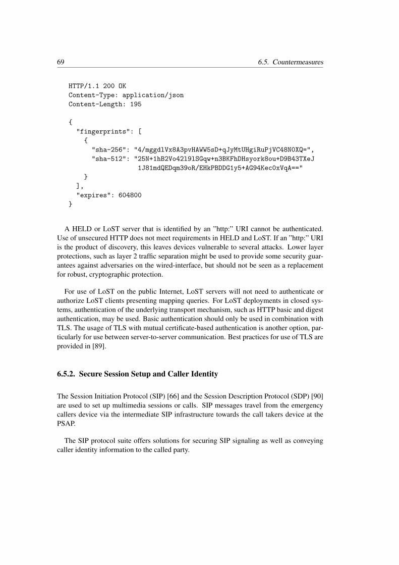
69 6.5. Countermeasures
HTTP/1.1 200 OK
Content-Type: application/json
Content-Length: 195
{
"fingerprints": [
{
"sha-256": "4/mggdlVx8A3pvHAWW5sD+qJyMtUHgiRuPjVC48N0XQ=",
"sha-512": "25N+1hB2Vo42l9lSGqw+n3BKFhDHsyork8ou+D9B43TXeJ
1J81mdQEDqm39oR/EHkPBDDG1y5+AG94Kec0xVqA=="
}
],
"expires": 604800
}
A HELD or LoST server that is identified by an ”http:” URI cannot be authenticated.Use of unsecured HTTP does not meet requirements in HELD and LoST. If an ”http:” URIis the product of discovery, this leaves devices vulnerable to several attacks. Lower layerprotections, such as layer 2 traffic separation might be used to provide some security guar-antees against adversaries on the wired-interface, but should not be seen as a replacementfor robust, cryptographic protection.
For use of LoST on the public Internet, LoST servers will not need to authenticate orauthorize LoST clients presenting mapping queries. For LoST deployments in closed sys-tems, authentication of the underlying transport mechanism, such as HTTP basic and digestauthentication, may be used. Basic authentication should only be used in combination withTLS. The usage of TLS with mutual certificate-based authentication is another option, par-ticularly for use between server-to-server communication. Best practices for use of TLS areprovided in [89].
6.5.2. Secure Session Setup and Caller Identity
The Session Initiation Protocol (SIP) [66] and the Session Description Protocol (SDP) [90]are used to set up multimedia sessions or calls. SIP messages travel from the emergencycallers device via the intermediate SIP infrastructure towards the call takers device at thePSAP.
The SIP protocol suite offers solutions for securing SIP signaling as well as conveyingcaller identity information to the called party.
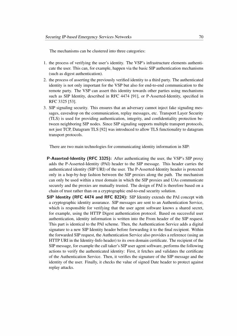
Securing IP-based Emergency Services Networks 70
The mechanisms can be clustered into three categories:
1. the process of verifying the user’s identity. The VSP’s infrastructure elements authenti-cate the user. This can, for example, happen via the basic SIP authentication mechanisms(such as digest authentication).
2. the process of asserting the previously verified identity to a third party. The authenticatedidentity is not only important for the VSP but also for end-to-end communication to theremote party. The VSP can assert this identity towards other parties using mechanismssuch as SIP Identity, described in RFC 4474 [91], or P-Asserted-Identity, specified inRFC 3325 [53].
3. SIP signaling security. This ensures that an adversary cannot inject fake signaling mes-sages, eavesdrop on the communication, replay messages, etc. Transport Layer Security(TLS) is used for providing authentication, integrity, and confidentiality protection be-tween neighboring SIP nodes. Since SIP signaling supports multiple transport protocols,not just TCP, Datagram TLS [92] was introduced to allow TLS functionality to datagramtransport protocols.
There are two main technologies for communicating identity information in SIP:
P-Asserted-Identity (RFC 3325): After authenticating the user, the VSP’s SIP proxyadds the P-Asserted-Identity (PAI) header to the SIP message. This header carries theauthenticated identity (SIP URI) of the user. The P-Asserted-Identity header is protectedonly in a hop-by-hop fashion between the SIP proxies along the path. The mechanismcan only be used within a trust domain in which the SIP proxies and UAs communicatesecurely and the proxies are mutually trusted. The design of PAI is therefore based on achain of trust rather than on a cryptographic end-to-end security solution.
SIP Identity (RFC 4474 and RFC 8224): SIP Identity extends the PAI concept witha cryptographic identity assurance. SIP messages are sent to an Authentication Service,which is responsible for verifying that the user agent software knows a shared secret,for example, using the HTTP Digest authentication protocol. Based on successful userauthentication, identity information is written into the From header of the SIP request.This part is identical to the PAI scheme. Then, the Authentication Service adds a digitalsignature to a new SIP Identity header before forwarding it to the final recipient. Withinthe forwarded SIP request, the Authentication Service also provides a reference (using anHTTP URI in the Identity-Info header) to its own domain certificate. The recipient of theSIP message, for example the call taker’s SIP user agent software, performs the followingactions to verify the authenticated identity: First, it fetches and validates the certificateof the Authentication Service. Then, it verifies the signature of the SIP message and theidentity of the user. Finally, it checks the value of signed Date header to protect againstreplay attacks.
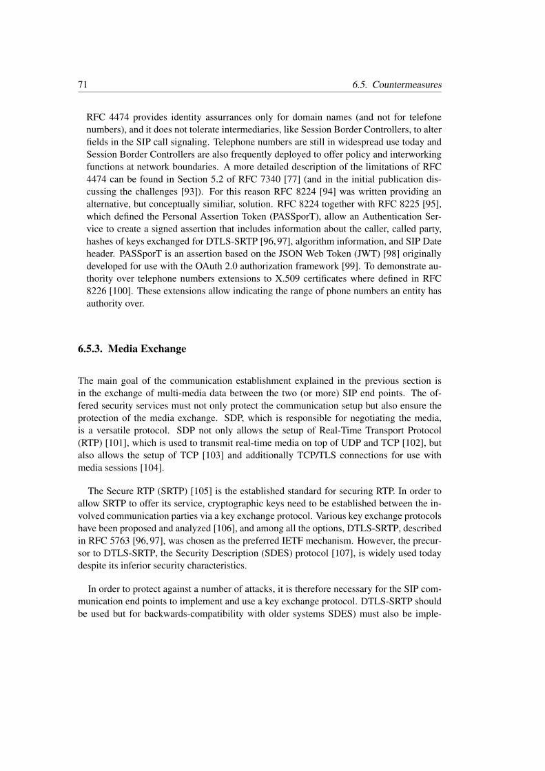
71 6.5. Countermeasures
RFC 4474 provides identity assurrances only for domain names (and not for telefonenumbers), and it does not tolerate intermediaries, like Session Border Controllers, to alterfields in the SIP call signaling. Telephone numbers are still in widespread use today andSession Border Controllers are also frequently deployed to offer policy and interworkingfunctions at network boundaries. A more detailed description of the limitations of RFC4474 can be found in Section 5.2 of RFC 7340 [77] (and in the initial publication dis-cussing the challenges [93]). For this reason RFC 8224 [94] was written providing analternative, but conceptually similiar, solution. RFC 8224 together with RFC 8225 [95],which defined the Personal Assertion Token (PASSporT), allow an Authentication Ser-vice to create a signed assertion that includes information about the caller, called party,hashes of keys exchanged for DTLS-SRTP [96,97], algorithm information, and SIP Dateheader. PASSporT is an assertion based on the JSON Web Token (JWT) [98] originallydeveloped for use with the OAuth 2.0 authorization framework [99]. To demonstrate au-thority over telephone numbers extensions to X.509 certificates where defined in RFC8226 [100]. These extensions allow indicating the range of phone numbers an entity hasauthority over.
6.5.3. Media Exchange
The main goal of the communication establishment explained in the previous section isin the exchange of multi-media data between the two (or more) SIP end points. The of-fered security services must not only protect the communication setup but also ensure theprotection of the media exchange. SDP, which is responsible for negotiating the media,is a versatile protocol. SDP not only allows the setup of Real-Time Transport Protocol(RTP) [101], which is used to transmit real-time media on top of UDP and TCP [102], butalso allows the setup of TCP [103] and additionally TCP/TLS connections for use withmedia sessions [104].
The Secure RTP (SRTP) [105] is the established standard for securing RTP. In order toallow SRTP to offer its service, cryptographic keys need to be established between the in-volved communication parties via a key exchange protocol. Various key exchange protocolshave been proposed and analyzed [106], and among all the options, DTLS-SRTP, describedin RFC 5763 [96, 97], was chosen as the preferred IETF mechanism. However, the precur-sor to DTLS-SRTP, the Security Description (SDES) protocol [107], is widely used todaydespite its inferior security characteristics.
In order to protect against a number of attacks, it is therefore necessary for the SIP com-munication end points to implement and use a key exchange protocol. DTLS-SRTP shouldbe used but for backwards-compatibility with older systems SDES) must also be imple-

Securing IP-based Emergency Services Networks 72
mented.
6.5.4. Mapping Database Security
Chapter 5 the use of the LoST protocol as part of the distributed mapping architecture isdescribed and LoST Sync allws to distribute mappings between LoST server nodes.
Exchanging mapping information is a security sensitive task. A minimum requirement isto authenticate neighboring server nodes using available HTTP security mechanisms, suchas HTTP Digest [108], HTTP Basic [108] over TLS, or plain TLS with client and servercertificates [109].
The setup of the LoST server relationships requires some manual configuration and hencethe choice of the security mechanisms used between the two entities is a deployment spe-cific decision. Nevertheless, the usage of certificates is an attractive option since it allowsthe use of a Public Key Infrastructure (PKI) with trust anchors dedicated to the emergencyservices. Whenever a new server is add a new certificate is obtained from the correspondingCertification Authority (CA). This certificate is then ready for use by the other infrastruc-ture elements without additional administrative configuration burden. In any case, the twocommunicating end points must authenticate each other and utilize the established securecommunication channel (i.e., an integrity protected exchange of data with the help of theTLS Record Layer) to avoid the possibility of injecting bogus mappings.
A malicious entity could, however, intentionally modify mappings or inject bogus map-pings. To avoid one entity claiming a service boundary belonging to some else, any nodeintroducing a new service boundary must digitally sign the mapping and thereby protect thedata with an XML digital signature. This ensures that a new mapping is associated to a par-ticular owner with non-repudiation properties. Absent any automatic procedures, a systemadministrator must approve the received mapping prior to its inclusion in the database. De-termining who can speak for a particular region is inherently difficult unless there is a smallset of authorizing entities that all other participants can trust. Receiving systems should beparticularly suspicious if an existing coverage region is replaced with a new one containingdifferent contact points. With this end-to-end security mechanism, it is nevertheless guaran-teed that mappings are modified by servers forwarding them as part of the synchronizationprocedure.

Chapter7Securing Data-Only Emergency Calls
7.1. Introduction
The Internet allows endpoints to communicate a variety of information through the networkwithout any changes to the underlying infrastructure. The work on IP-based emergencyservices was initially focused on making voice communication functioning well. Later theattention was shifted to other forms of communication, including real-time text, video andreal-time text. Even more recently is the idea to enhance emergency services communica-tion with data collected by Internet of Things devices. In the emergency services communitythe term ”data-only emergency call” is used to refer to devices that typically send data, notvoice or not just voice, to PSAPs to help facilitate emergency services support. The commu-nicated information may be crash data of a vehicle, data from a smoke sensor, water levelinformation, structural information of a bridge, etc. In general, the idea is to increase situa-tional awareness for the emergency services personnel and other interested parties (such asthe owner of a building).
Over the last few years, the number of Internet of Things (IoT) deployments has seen asteady increase. Heterogeneous, innovative IoT hardware is being rolled out at a fast pace,catalyzed by the new availability of open-source, general-purpose, embedded IoT softwareand open standards for IoT communication.
In parallel, alarming recent reports in both academic work and mainstream media warnabout potential cyber-vulnerabilities and actual cyber-attacks involving IoT. Increasedawareness of the need for improved security is pushing legislators to pay closer attentionto the IoT environment and issue new regulations, such as the first IoT cybersecurity law(SB-327) and, more recently, the European Commission’s Cybersecurity Act.
Securing Data-Only Emergency Calls 74
In this chapter, we focus on constrained IoT devices (described in RFC 7228 [110]).Typically, constrained IoT devices use microcontrollers - for instance Arm Cortex-M - onwhich run real-time operating systems, such as FreeRTOS, Micrium’s µC/OS, RIOT, orMbed OS [111]. Compared to machines that run full-blown operating systems, such asLinux, constrained IoT devices use a fraction of the power and are equipped with RAMand Flash sizes (in the kilobyte range) reminiscent of the days of the Commodore VIC-20.Constrained IoT devices, which cannot afford the energy drain of Wi-Fi, connect to thenetwork via low-power, wireless, link-layer technologies, such as Bluetooth Low-Energy,IEEE 802.15.4, LoRa, 3GPP Cellular IoT (NB-IoT), or via wired buses.
IoT devices are, in many case, purpose built devices.
Although EU initiatives, such as IoT security recommendations from ENISA [112]11
pave the way for more secure IoT, reports about utterly insecure IoT devices keep pouringin.
In 2014 [2] we surveyed standardization activities on Internet of Things. Most standard-ization activities were only at the beginning and, in other cases, concepts were not yet readyfor standardization and required further research. At that time multi-hop mesh network-ing using IEEE 802.15.4 and data compression over this low power networking technologyreceived a lot of attention.
5 years later, in 2019, we were wondering whether it is in the meanwhile possible todevelop an IoT product, such as a device used for emergency services, and secure it withopen standards. While there are still lots of proprietary technologies are on the market,analysing the situation with open standards is beneficial for two reasons: first, the use ofstandards reduces or avoids vendor lock-in, and second the specifications are publicallyavailable.
As a metric for a secure IoT product the ENISA recommendations are used. Follow-ing the earlier survey the focus is on Internet protocol specifications for network securitystandardized by the IETF. The focus on the IETF is motivated both because it has beensuccessful in standardizing many other Internet protocols that underpin the Internet at large,and because IETF protocols standards aim to work across the various IoT link-layer tech-nologies.
11European Union Agency for Network & Information Security (ENISA) ’Baseline Security Recommenda-tions for IoT’, and ’Good Practices for Security of Internet of Things in the context of Smart Manufacturing’.

75 7.2. Deployment Scenarios
7.2. Deployment Scenarios
Deployments for IoT devices that are used in the context of emergency services are typicallydeployed in three configurations:
• First, devices communicate with the ESINet via some service provider. This deploymentmodel is, for example, found in roadside assistence solutions where the service provideroffers a range of other functions besides emergency services support.
• Second, devices are connected to the cloud-based IoT service via some form of gateway.The use of a gateway is typically needed when devices use short-range radio technologies,such as IEEE 802.15.4 or Bluetooth Mesh. The gateway ensures that the exotic IoT radiotechnologies are integrated into the rest of the network infrastructure. Sometimes thegateway also offers application layer protocol translation. A smoke detector connected toa multi-hop mesh network using IEEE 802.15.4 is an example for such deployment.
• Third, IoT devices may be connected directly to the Internet using classical cellular tech-nology or some of the recently developed low power wide area networking technologies,such as NB-IoT. A sensor built into a bridge is an example for this deployment.
Figure 7.1 shows these deployments graphically. A more detailed discussion about dif-ferent IoT deployment models can be found in [113].
ESINet
Server
IoT Device
IoT Device
Gateway
Service Provider
ServerIoT Device
Figure 7.1.: IoT Deployment Scenarios.
In rare cases IoT devices directly interact with each other.

Securing Data-Only Emergency Calls 76
7.3. Security and Privacy Threats
7.3.1. Categories of Attacks
The common approach to designing a security solution is to conduct a threat analysis first.Broadly, attacks can be categorized (as depicted in Fig. 7.2) into (i) network (or communi-cation) attacks, (ii) software attacks, and (iii) hardware attacks.
Level 1
Cost/EffortTo Attack
Cost/EffortTo Secure
Communication Attacks Man-in-the-Middle Replay and DoS attacks Integrity violation Eavesdropping
Software Attacks Buffer overflow
and ROP SQL injection CSRF Privilege Escalation Session hijacking
Hardware Attacks Side-channel attacks
(such as timing, power analysis, and electromagnetic attacks)
Fault injection Depackaging of the device Interfacing exposed hardware interfaces
(e.g., UART, SPI, I2C, and debug interfacessuch as JTAG)
Level 2
Level 3
Figure 7.2.: Categories of Threats.
Historically, the IETF focused on countering network attacks, and ignored software andhardware attacks. For this reason, the main threat model, as described in RFC 3552 [114],is a classical network attacker who can carry out active and passive attacks against thecommunication interaction. Only recently, the IETF started tackling some security concernsbeyond network attacks, with the work on attestation, trusted execution environments, andfirmware updates (see Section 7.5.7).

77 7.3. Security and Privacy Threats
Privacy-related threats were added later with RFC 6973 [115] and are now being con-sidered in the design of protocols throughout the IETF, including IoT protocols. In somescenarios there is an overlap of privacy and security threats (for example, in a surveillancescenario), and there are some privacy-specific threats, such as data minimization and userparticipation. The threat of pervasive monitoring, as revealed by Snowden, certainly had ahuge impact on recognizing the importance of privacy in the design of Internet protocols,as documented by the IETF community in RFC 7258 [116].
7.3.2. Threat Modelling
In considering which assets have to be protected, in many cases it is fairly obvious whatthe threats are, even for someone who is less familiar with security. Unfortunately, threatanalysis is a process that is iterative and creative because product design decisions can createnew threats and the deployment environment may also change over time. As such, it is oftennecessary to examine the threats not only once, at the beginning of the product developmentprocess, but also to adjust the list of threats during the product lifecycle.
The following are three examples that illustrate the creative nature of the threat analysisactivity:
• Consider an emergency services product that is sold to consumers and deployed in theirhome. Often these products are considered physically secure because a thief breaking intosomeone’s home is probably less interested in tampering with a smoke detector. However,if the same customer sometimes rents his home to strangers, via services like Airbnb,the threat model has to be re-evaluated. This case illustrates a potential change in thedeployment environment. Accurate threat modelling requires a good understanding ofhow IoT devices are used and other changes in the threat landscape over the lifetime ofthe device.
• Consider another emergency services product that uses state-of-the-art crypto with a rock-solid security protocol to authenticate and protect a firmware update mechanism. Imaginefurther that the engineers of this product decide to deploy the same symmetric key, a classkey, on all devices of the same product family. In this scenario, an attacker only hasto buy and analyze a single device - for example, by conducting a (novel) side channelanalysis - to obtain the class key and ship a firmware update to all devices in the sameproduct family. In the worst case, the attacker can deliver the firmware updates overthe Internet without having to be in close proximity to the devices. This example showshow the changing capabilities of attackers can change the threats posed. The peopleconducting the threat modelling must be aware of the attackers’ techniques and their levelof sophistication.

Securing Data-Only Emergency Calls 78
• Consider a final example where the threat analysis addresses all assets the company sell-ing the product cares about. Later, it turns out that the product is vulnerable to a reflectionattack, which was not considered in the threat analysis because the computing resourcesof third parties (the victims of the attack) were not included in the asset list. Those in-volved in threat modelling have to be aware of the type of attacks encountered in specificindustries today.
7.4. Overview of ENISA Guidelines
Once an initial set of threats is collected, it is time to think about which of those threatsshould be dealt with, and how. Although a company may decide not to offer a technicalsolution to all security threats, it is useful to consult industry guidelines, such as the ENISAguidelines [112], which can help to make reasonable decisions. While many security re-quirements relate to the software and hardware implementation of a product, such as theboot process and hardware crypto, there are also many protocol-specific elements that areimportant security considerations.
Here is a list of the most important groups of security considerations:
1. Authentication and communication security2. Object security3. Authorization and access control4. Key management5. State-of-the-art crypto6. Restrictive communication7. Firmware and software updates
Many of the requirements that fall into these seven groups can also be found in otherbest current practice guides. In fact, there is an astonishing overlap among the guidelinesproduced by governments, industry groups, security experts, and researchers. This givesus confidence that these guidelines indeed represent a consensus of sorts among securityexperts.
Interestingly, the seven groups listed above can be mapped loosely to areas of work inthe IETF. In the next section a high-level overview of the ongoing standardization work isprovided.

79 7.5. IETF IoT Security Standardization
7.5. IETF IoT Security Standardization
The network security mechanisms surveyed aim to be applicable to all communication pat-terns described in RFC 7452 [113]. The deployment scenarios illustrated in Section 7.2 aremost relevant in today’s deployments.
7.5.1. Authentication and Communication Security
The IETF work on offering communication security for IoT devices resulted in the consoli-dation of Transport Layer Security (TLS) and Datagram Transport Layer Security (DTLS).RFC 7925 [117] defines profiles of TLS and DTLS 1.2 for use in IoT environments withseparate guidance for three types of credentials supported by TLS/DTLS, namely pre-sharedsecrets, raw public keys, and certificates. Password-based techniques, which have also beendefined for TLS/DTLS, are not discussed, because the industry is, in general, trying hardto move away from password-based authentication. Since the publication of RFC 7925 in2016, more and more embedded TLS/DTLS stacks that support the recommendations inthis specification are available for developers.
Over the last few years, the IETF has been busy standardizing the new version of TLS,in the form of version 1.3, inspired by the needs of the web developer community, whichwanted to reduce the round-trip latency of the handshaking protocols. TLS required tworoundtrips before application data could be exchanged securely. The standardization pro-cess for TLS 1.3, now published in RFC 8446 [118], was started in April 2014 and com-pleted in August 2018. The list of changes and new features is long, which has contributedto the longer standardization process. The reviews by a large number of participants, earlyimplementation and interoperability efforts, deployment investigations, and the use of for-mal methods have contributed to the longer standardization process, but these contributionssignificantly improved the quality of the specification.
The new features of TLS 1.3 are:
• A reduced number of roundtrips. The 0-RTT exchange enables transmitting applicationdata with the first message (at the loss of replay protection, which has to be providedby the application layer). With the regular exchange, a client can send application dataafter the first roundtrip. To convey the necessary information, the client has to add extrainformation into the ClientHello message. The assumption is that the client will knowthe server, or at least maintain some information about the server, and that configurationinformation, such as algorithms, rarely changes.

Securing Data-Only Emergency Calls 80
• The three Pre-Shared Key (PSK)-based modes (PSK-based authentication, session re-sumption, and session resumption without server-side state) have been merged into asingle mode. Password-based authentication, which was available in TLS/DTLS 1.2 withSRP [119] and J-PAKE [120], was removed.
• Encryption of handshake information is made as early as possible. While this makesnetwork monitoring and debugging more complex, it also increases privacy protection.The ability to add padding to messages was also added to make traffic analysis moredifficult.
• A modified ciphersuite concept, in which the negotiation of the algorithms has been un-tangled from the authentication and key exchange. The ciphersuite list was thereby alsocleaned up.
• Increased use of perfect forward secrecy, which requires a Diffie-Hellman exchange.• Removed key transport, a decision which was met with considerable scepticism by en-
terprise network operators and firewall vendors since it requires more sophisticated inter-ception techniques to perform deep packet inspection.
• Use of authenticated encryption with additional data as the go-to-choice for symmetricalgorithms.
• Removed custom Diffie-Hellman groups and compression.• Redefined renegotiation with the introduction of a post-handshake authentication mecha-
nism.• Added solid version negotiation.• The key derivation algorithm now makes use of the HMAC-based Extract-and-Expand
Key Derivation Function (HKDF) construct defined in RFC 5869 [121] and a more struc-tured key hierarchy, which enables researchers to better analyze the handshake using for-mal methods because of the various keys are independent. From an implementation pointof view, this change led to a larger code size compared to earlier TLS versions.
With this long list of features it was interesting to get more data about the impact oncode size, message overhead, and the number of cryptographic operations. With a TLS 1.3stack implemented on top of the Mbed TLS library an early conclusion can be drawn thatTLS 1.3 provides an improvement for IoT deployments in terms of security, privacy andperformance at roughly the same code size and with the same RAM requirements.
The work on DTLS 1.3 [122] was started with a slight delay and is currently being final-ized. DTLS aims to provide communication security for connectionless transport protocols.This allows developers to secure protocols that are primarily used over the User DatagramProtocol (UDP), such as the Constrained Application Protocol (CoAP). The design of DTLS1.3 reuses TLS 1.3 as much as possible. There are, however, several aspects that are worthhighlighting:

81 7.5. IETF IoT Security Standardization
• DTLS requires an enhancement for denial of service protection. This is accomplishedwith a dedicated message in earlier versions of DTLS, namely the HelloVerifyRequesthandshake message. In DTLS 1.3, this message has been replaced by the HelloRetryRe-quest message, which was already introduced in TLS 1.3.
• The record layer encoding has been optimized. The version number and type fields havebeen removed, the length of the epoch and sequence number fields have been shortened,and the header uses a variable length encoding. This lowers the over-the-wire overhead.
• The retransmission mechanism has been redefined. Prior to DTLS 1.3, the retransmissiongranularity was at the level of an entire flight (in other words, retransmission required aseries of messages). In DTLS 1.3, an explicit ACK message has been defined to enableacknowledgements of handshake messages explicitly.
• DTLS 1.3 introduces a connection ID concept, which enables lookup of the security as-sociation of an incoming record based on a newly introduced identifier carried in therecord layer header rather than using the source IP address and source port. The connec-tion ID concept is particularly useful in an IoT context where devices sleep for extendedtime periods and likely run into the problem of an expired state with network addresstranslators. In light of the popularity of this extension, it has also been backported toDTLS 1.2 [123], although with weaker privacy characteristics because DTLS 1.2 doesnot support post-handshake messages. Maintaining the same level of privacy while intro-ducing this new feature was important in the design, and also led to the introduction ofa sequence number encryption scheme for DTLS 1.3. This extension enables the use ofan established security context for significantly longer without the need to rerun full orresumption handshakes, and results in a significant performance improvement.
We expect TLS and DTLS 1.3 to find widespread usage on the Internet and in IoT de-ployments.
When security requirements include end-to-end communication security, a reasonablequestion is what the ’endpoints’ of this exchange are. In some cases, it may be sufficient tooffer security at the link layer since the two ends are topologically close to each other andsometimes a more complex communication path is utilized. A properly described systemarchitecture will give insight into what the participating entities are.
Here is a typical example of an IoT device in an emergency services context that com-municates with support infrastructure provided by the manufacturer. The IoT device usesa radio technology to connect to the Internet; for example, to a Wi-Fi network. Once itconnects to the Internet, it contacts a device management server. The device managementserver is responsible for configuring the device, and for managing software updates. Theentire lifecycle of the IoT device is managed by the device management server. Dependingon the deployment preferences this device management server may also be used to retrieve

Securing Data-Only Emergency Calls 82
sensor values and to triggering actuators, if there are any. If we want to secure communica-tion end-to-end, security protection has to start and end at the two endpoints, namely at theIoT device and the device management server. TLS and/or DTLS would be a fine choicefor providing end-to-end security.
In addition to the TLS/DTLS, the IETF now offers another communication security so-lution called ’Object Security for Constrained RESTful Environments’ (OSCORE [124]).The development of OSCORE was initially started as an application layer security solutionprotecting CoAP messages end-to-end. Later, it was extended to work also when CoAPtraffic is mapped to HTTP because end-to-end communication in IoT deployments rarelyuses CoAP alone. Since the SIP protocol is often used for emergency services OSCOREis not a good choice since OSCORE does not support SIP and SIP itself is not a RESTfulprotocol.
For those cases where CoAP is used instead of SIP, and DTLS/TLS is considered insuf-ficient, OSCORE may be a possible candidate for a security protocol. OSCORE re-usesCOSE [125] for protecting CoAP messages, or more precisely some CoAP headers and theCoAP payload. The reason it offers it cannot protect the entire CoAP message is that theCoAP also defines intermediaries, so-called CoAP proxies, and those proxies need to in-spect part of the message. CoAP defines the interaction between CoAP and DTLS slightlydifferently to how HTTP did. In CoAP, DTLS is terminated at the proxy while in HTTPa TLS exchange is transparently passed through (unless it is a reverse proxy). Note thatin context of OSCORE, these proxies can also be special CoAP-to-HTTP proxies as longas they do not change the nature of the REST API interaction (and for the CoAP-to-HTTPmapping guidance described in [126]).
Since the OSCORE specification does not define a key management mechanism, theACE-OAuth framework [127] is re-used to facilitate that functionality. The design followsthe use of DTLS/TLS between the ACE-OAuth client and the resource server whereby theauthorization server issues a proof-of-possession token along with the key to the client. Theclient then uses that key to derive keys for OSCORE, and then secures the communicationwith the resource server using OSCORE. This solution [128] is now being standardizationin the ACE working group.
7.5.2. Object Security
Communication security protocols typically protect the exchanges of parties over a longerperiod of time. These security protocols, as can be seen with TLS, often operate in variousstages where computationally-heavy tasks are performed infrequently as part of a hand-
83 7.5. IETF IoT Security Standardization
shake, while application data protection is accomplished with symmetric keys derived dur-ing the handshake. We described those communication security protocols in Section 7.5.1.
In this section we focus on security technologies that are tailored toward one-shot pay-loads. For example, consider a scenario where firmware images are distributed by the devicemanagement server and must be secured end-to-end, from the developer to the IoT device.Since the firmware image may be stored on servers for an extended period of time and mustbe self-contained, a different security mechanism, such as COSE [125], is more appropriate,and we cover it next.
In computer science, we like to come up with encoding and serialization formats, and themost recent trend is the Concise Binary Object Representation (CBOR) [125], which wasdesigned with a small code and message size in mind. To protect data that is encoded inCBOR, a new signing and encryption format, which is conceptually similar to JavaScriptObject Signing and Encryption (JOSE), the signing and encryption format for JSON en-coded data, had to be developed. (The functionality for JOSE is spread over different speci-fications; the most important documents are JSON Web Encryption (JWE) [129] and JSONWeb Signature (JWS) [130]). JSON and JOSE was the way to encode data before CBORand COSE came along. COSE can be seen as a set of building blocks that applications usein the way they find useful (with an eye on code size). A device implementing a firmwareupdate solution may, for example, rely on asymmetric crypto and would, therefore, imple-ment the signature verification capability offered by COSE and none of the other securityservices that use symmetric key crypto.
COSE offers the following security services:
• Digital signatures• Counter signatures• Message Authentication Code (MAC)• Encryption• Rudimentary key distribution methods
Most security services are offered in two versions, depending on whether one or multipleentities create or receive them. For example, the COSE Sign1 signature structure is usedwhen only one signature will be placed on a message, whereas COSE Sign allows for oneor more signatures to be applied. COSE Sign1 and COSE Sign are different structures andcannot be converted from one to the other.
The standardization work on COSE was finished 2017 and the RFC was published mid-2017; therefore the availability of embedded COSE libraries is limited today. libcose and

Securing Data-Only Emergency Calls 84
cose-c are two early implementations, released mid-2018, tailored for use in the microcon-troller environment.
Since CBOR is a good fit for securing data when the goal is to protect one-shot mes-sages, the use of COSE is one option for protecting firmware updates, or more precisely, forsigning metadata about the firmware and, optionally, encrypting the firmware image. COSEcan also protect access tokens used with the ACE-OAuth framework. Both examples aredescribed in more detail in subsequent sections.
Since emergency services standards do not encode data in JSON or CBOR there are fiveapproaches for securing such data:
1. New specifications are defined that define a new serialization format. For example, it ispossible to encode a PIDF-LO in JSON or in CBOR. This approach allows the use ofJOSE and COSE, respectively.
2. No changes to the existing specifications are made and data is treated as an uninterpretedbyte sequence. This specifically allows the use of signatures over detached data.
3. Available security mechanisms suitable for use with the existing serialization formats areused. For example, in case of XML this would be XML digital signatures and XMLencryption. Other data can be protected using the Cryptographic Message Syntax (CMS).CMS uses ASN.1 under the hood, which is also used in X.509-based certificates.
4. A compression technique is used on data that is encoded in XML before it is signed and/orencrypted. Such approach may only require a new media-type to be used, or a new mediatype to be registered with IANA.
5. Communication security is provided by TLS/DTLS where possible with object securityonly for selected parts, such as firmware updates.
7.5.3. Authorization and Access Control
Securing communication interactions is an important step to mitigate basic attacks. ManyIoT devices used for emergency services, such as vehicles eCall systems as well as sensors,may need to be accessed by technicians and even end users. This interaction raises a numberof authorization questions, including
• How can access to the device be secured, without inadvertently allowing unauthorizedaccess?
• Is it possible to support different users or groups of users?• Can the access rights of one user be set differently from other users?

85 7.5. IETF IoT Security Standardization
• Can access control policies be managed centrally?• Does the solution scale for a greater number of devices?• How can strong authentication mechanisms be utilized?
The IETF Authentication and Authorization for Constrained Environments (ACE) work-ing group has developed a solution to answer the above-listed questions, based on the widelyused OAuth 2.0 protocol [99], and brings fine-grained authorization to the IoT world. Thisbody of work is called ACE-OAuth [127] and the specifications are already further alongwith interoperability tests taking place. While OAuth 2.0 was designed with a wide rangeof use cases in mind - such as the web, native apps on smart phones, tablets and desktopcomputers, browser-based apps, and even devices with a limited user interface, such as TVs,picture frames, and game consoles - a few enhancements had to be made to tailor OAuth tothe constrained IoT environment.
First, let us briefly summarize how ACE-OAuth is expected to work at a high-level. TheOAuth system consists of four main entities, namely the client, the resource server, the au-thorization server, and the resource owner. The client wants to access a protected resource ata resource server. In an example of a vehicle-based emergency services solution, the clientcould be software running on the tablet of a technician, and the resource server is softwarerunning on a microcontroller inside the vehicle. The authorization server is responsible forissuing tokens that allow the client to access the emergency services system in the vehiclesuch that the authorization policies stored at the authorization server are met. These au-thorization policies may be created by the car manufacturer (acting as a resource owner)or phrased differently the resource owner decides about who gets access to the protectedresource.
The token, which is issued by the authorization server and consumed by the resourceserver, is called the access token. The OAuth working group standardized a token format,called JSON Web Token (JWT) [98], which encodes claims in JSON, and the token itselfis protected using the mechanisms developed in the IETF JOSE working group. Since theOAuth 2.0 specification does not mandate a token format, it is possible to design and use atoken format that works best in each environment. In the case of ACE-OAuth, a counterpartto the JWT was developed with the CBOR Web Token (CWT) [131], which uses CBORinstead of JSON, and COSE and instead of JOSE. The result is a smaller token size.
Access tokens used in OAuth 2.0-based deployments are mostly bearer tokens. Proof-of-possession (PoP) tokens were introduced later [132, 133], and in the IoT environment it ispossible to use PoP tokens from the beginning. The key characteristic of a PoP token is thatthe token itself is associated with a symmetric or asymmetric key, and the entity presentingthe token must demonstrate possession of the key. When a public key is associated with the

Securing Data-Only Emergency Calls 86
PoP token, this means that the client must use the private key along with a digital signaturewhen demanding access to a protected resource on a resource server. An attacker, therefore,needs to steal the key associated with the token in addition to the token itself. The use ofPoP tokens requires an enhancement to the original OAuth 2.0 specification because extrainformation about the keys to be bound to the tokens must be passed around.
The second enhancement to the OAuth 2.0 specification accommodates for the differentprotocols being used in the IoT environment. While HTTP is used for IoT communication,the Constrained Application Protocol (CoAP) and the Message Queuing Telemetry Trans-port (MQTT) protocol are also popular. OAuth 2.0 has not been developed for use withthese protocols, and the necessary extensions are defined in the IETF ACE working group.
Concurrently with the work on ACE-OAuth, work on an Entity Attestation Token (EAT)format [134], which introduces attestation-specific claims for use in the CWT structure, hasbeen contributed to the IETF. The promise is to enable IoT devices to communicate informa-tion about their hardware and software characteristics to other communication parties. Thiswork is still at an early stage, and the ambition is to create a working group. These EATtokens could provide information about the manufacturer, used hardware security features,and hashes computed over the bootloader and firmware code of the device to a communi-cation party, opening up additional decision-making possibilities. For emergency servicesapplications the extra security properties provided by this attestation information could behighly valuable.
7.5.4. Key Management
IoT devices need several keys to enable lifecycle management and remote management.As explained in the Internet Protocol for Smart Objects (IPSO) Alliance (now OMA Spec-Works) publication on credential management for IoT devices [135], a common securityassumption is that IoT devices have been provisioned with at least one long-term credentialduring manufacturing. This long-term credential is then used to provision further keys tothe device in a process called bootstrapping, commissioning, onboarding, or enrollment.This new terminology hides the fact that the developed protocols provide two main steps:
1. The device authenticates itself to another party and vice versa using a pre-provisionedcredential. In many cases, this credential is provided during manufacturing. For example,a device may be provisioned with a unique device certificate along with a private key. Thiscredential is then used to authenticate the device to the other party in a communicationinteraction. To offer mutual authentication, the device must also be provisioned with oneor multiple trust anchors. There is, however, one important exception where devices start

87 7.5. IETF IoT Security Standardization
without having credentials provisioned, and they use an out-of-band mechanism to obtainsecurity guarantees. Bluetooth Low Energy, for example, uses this approach where inproximity, a PIN entry, is used as a security guarantee to skip the provisioning step.
2. A protocol exchange is required to convey or derive new credentials. These new keys,often called operational credentials, are used to secure the communication of the device,including data and configuration exchanges.
Many vendors and standards developing organizations have designed protocols that pro-vide this bootstrapping functionality. Some of these protocols are specified for use with aspecific radio technology (as the Bluetooth Low Energy example shows) and others are ra-dio technology agnostic (or at least to a large extend). Organizations and vendors that havedeveloped these bootstrapping techniques include OMA SpecWorks (with the LightweightMachine-to-Machine (LwM2M) protocol [136]), Open Connectivity Foundation (OCF),Thread Group, Intel (with their Secure Device Onboarding), IEEE (Device ProvisioningProtocol), Alljoyn, WiSun, Zigbee, and Bluetooth (Mesh).
Unsurprisingly, the IETF has also developed a number of these protocols for use inIoT environments, as outlined in this survey [137]. Examples include ZeroTouch, ANI-MA/BRSKI, Enrollment over Secure Transport (EST), EAP-NOOB, ACE-OAuth, Certifi-cate Management Protocol (CMP), PANA, and EAP/AAA.
7.5.5. State-of-the-Art Crypto
Cryptography is a conservative business. Developing a new cryptographic algorithm, writ-ing proofs, publishing papers, and standardizing the cryptography is not enough to makeit see widespread adoption, or any adoption at all. Years of community-wide review istypically required, which makes cryptography quite costly in terms of development. Anengineer given the task of developing software for an IoT product is therefore well servedto rely on off-the-shelf crypto rather than going for the cutting edge. Resisting the urge todevelop your own cryptographic algorithm is key.
With the work on the TLS 1.3 specification [118], the IETF TLS group cleaned up theciphersuite list, and the recently published TLS 1.3 specification, therefore, contains a listof algorithms that can be considered a good choice. We use the crypto recommendationsfrom the TLS 1.3 specification since the RFC has recently been published and it representsthe consensus of the IETF community in terms of crypto protocols. While these algorithmrecommendations are tailored to TLS 1.3, they are typically also applied to other protocoldesigns. The recommendations have been developed in cooperation with the Internet Re-search Task Force’s (IRTF) Crypto Forum Research Group (CFRG). Here is what the spec

Securing Data-Only Emergency Calls 88
suggests:
• For symmetric key cryptography, the industry has moved to authenticated encryptionwith additional data (AEAD) ciphers. AES-128-GCM-SHA256 is the ’must’-implementalgorithm, and the same AEAD algorithm with a longer key size, namely AES-256-GCM-SHA256, is a ’should’-implement. As a backup cipher, CHACHA20-POLY1305-SHA256 has become popular and it is also a ’should’-implement.
• For digital signatures with certificates, the TLS 1.3 spec indicates that RSA-PKCS#1-SHA256, RSA-PSS-RSAE-SHA256 and ECDSA-SECP256r1-SHA256 are mandatoryto implement.
• For the key exchange, the NIST P-256r1 curve (secp256r1) is mandatory to implement.Implementations ’should’ support key exchange with X25519, which is an alternativecurve (Montgomery).
There are two caveats:
• First, IoT devices often implement the Counter with CBC-MAC (CCM) in hardwarerather than the Galois/Counter Mode (GCM). The CCM mode of operation with AEShas been put into most, if not all, IoT specifications as the preferred algorithm. To reducethe overhead caused by the message authentication code (MAC), CCM also supports avariant with a shortened MAC, referred to as CCM-8. CCM-8 is commonly used in IoTdeployments.
• Second, most IoT deployments use Elliptic Curve Cryptography (ECC) rather than RSA.As such, the algorithm of choice for certificates today is ECDSA-SECP256r1-SHA256.
In the future, we may see convergence in the area of symmetric crypto algorithms usedon IoT devices and on the general Internet with ChaCha20 and Poly1305. It is also worthnoting that there have been standardization efforts around lightweight symmetric cryptog-raphy - for example, by NIST - but it is too early to say whether these algorithms willbe useful beyond a niche market. Modern low-end IoT hardware is equipped with a TrueRandom Number Generator (TRNG), very often supports SHA-256 and AES-128, and maysupport ECC-crypto. This is already a big improvement compared to the availability of evenTRNGs in microcontrollers a few years ago. The use of a TRNG is essential for securityprotocols because almost all security protocols rely on a source of randomness, for example,for nonces and key generation.

89 7.5. IETF IoT Security Standardization
7.5.6. Restricting Communication
Most IoT devices are built to fulfil a specific purpose; typically to collect sensor input,process it, and act on the results. In edge or fog computing, even sensor fusion is oftenoutsourced to a gateway, or it is delegated to the server-side infrastructure. Naturally, thecommunication interaction of such IoT devices is also limited, particularly since these de-vices have limited RAM, which prevents communication with multiple hosts concurrently.
The earlier work of the IETF Network Endpoint Assessment (NEA) working group aimedto develop an architecture and protocols to ”assess the posture of endpoint devices for thepurposes of monitoring compliance to an organization’s posture policy and optionally re-stricting access until the endpoint has been updated to satisfy the posture requirements”.At the time that NEA was standardized, the endpoints were mostly laptops and desktopsin enterprise networks. It became very difficult to write policies that described the posturepolicy in an organization for all endpoints, given their varying communication interactionmethods, and then to keep that policy up-to-date. In the end, the NEA standardization workhad less security impact than expected.
With the much simpler communication interaction of IoT devices, the idea of restrictingthe communication of these devices surfaced again in the work on the Manufacturer UsageDescription (MUD [138]). An organization interested in formulating a policy for whatan IoT device is allowed to do faces the challenge that it requires some analysis work todetermine which protocols a device is using, and with which hosts it is communicatingon the Internet. Only the company developing the final product has complete informationavailable about the communication behavior since it is in full control of developing (orselecting) the software stack.
Although IoT security recommendations highlight the need to remove unused services,network operators still inherently distrust the manufacturers of these devices. The currentassumption seems to be that IoT devices will not be developed with security in mind. Thislack of confidence in the ability to develop secure IoT devices has led network equipmentmanufacturers, network operators, and security start-ups to develop various schemes for”learning” whether an IoT device behaves correctly. While products on the market usesome form of deep packet inspection and analysis of communication interactions by inter-mediaries somewhere in the access network, the standardized solution expects the equip-ment manufacturer to publish MUD files that offer information about the communicationinteraction of the device. These MUD files are communicated from the IoT device to thenetwork using Dynamic Host Configuration Protocol (DHCP), or as part of the network au-thentication procedure via extensions in certificates. Equipment in the network then fetchesthese MUD files and uses the machine-readable description to create firewall policies auto-

Securing Data-Only Emergency Calls 90
matically. For example, it is expected that a device that misbehaves due to an attack will befirewalled, or at least that alerts will be generated. A manufacturer has to update these MUDfiles for each product whenever the communication interaction changes; for example, whenthe device interacts with different servers or uses alternative communication protocols.
At the time of writing, the standardization work on MUD is largely completed and itremains to be seen whether manufacturers who previously did not care about implementinga firmware update solution and alike can now be convinced to publish MUD files abouttheir products in a timely fashion. At the same time, many companies are trying hard toimprove the security of endpoints with new hardware security mechanisms and with readilyavailable open source code that takes most of the difficult security programming out of thehands of developers.
7.5.7. Firmware and Software Updates
Providing a firmware update solution for IoT devices is essential to dealing with bugs andthe changing environment. While this seems obvious, we still see lots of devices in themarket that do not enable updating their code. Best current practice guides not only demandthe ability to update firmware, but also the ability to do so securely. In 2017, the IETFformed the Software Updates for Internet of Things (SUIT) working group to standardize anIoT firmware update solution. The initial starting point was to outline the architecture [139]and the metadata describing a firmware image along with its security mechanism [140].The metadata contained in a data structure that is protected, at least against modifications,is called a manifest. IoT device management solutions, such as LwM2M [136], can then beused to deliver the manifest and the firmware image to IoT devices.
The manifest contains several elements to instruct an IoT device to install only firmwarethat comes from an authorized source, has not been modified, is (optionally) confidentialityprotected, is suitable for the hardware, and meets various other conditions. One item of theIETF SUIT working group is an information model document, which explains the purposeand the semantics of the manifest elements.
The IETF SUIT aims to cover a wide range of use cases, not only because the IoT marketis quite diverse in its deployment needs, but also because of the hardware being used. Sincemany IoT devices today contain multiple microcontrollers to perform different tasks, suchas radio communication and application processing, the manifest also has to provide anindication of which microcontroller must be updated. Likewise, a single microcontrollermay have software from different vendors, such as a Bluetooth software stack from the chipmanufacturer and application code from a developer. Transferring large firmware images

91 7.5. IETF IoT Security Standardization
can be a challenge for low-power radio technologies, and some vendors, therefore, prefer touse differential updates or to update selected components instead. The manifest also has tocover these use cases.
Dealing with different versions of firmware over the lifetime of the device is another arequirement. These scenarios require some form of dependency mechanism and versionmanagement. The use of an encrypted firmware image is also becoming more popularbecause it reduces the attack surface since knowledge of the code running on an IoT device,even if it must be reverse engineered with tools like Radare, Binary Ninja, or IDA Pro, givesan attacker a lot of additional insight. Obtaining a firmware image is often the first task inan attack chain.
While the standardization process in the IETF SUIT group is still ongoing, there has beeninterest in reusing existing building blocks, such as CBOR and COSE (discussed previouslyin this article), to encode and protect firmware images, respectively. Even if vendors onlyever update their own device in a siloed IoT deployment, it is still beneficial for them torely on a standardized solution to give others confidence that the solution has been designedproperly with input from a wide range of industry players, follows best current practices, andpotentially uses off-the-shelf code. The reuse of code also helps to reduce the developmenteffort since participants in the group intend to release a reference implementation as a by-product of the standardization activities. Some of the participants have verified the ongoingspecification work at IETF hackathons.
The IETF SUIT working group is somewhat related to the Trusted Execution Environ-ment Provisioning (TEEP) working group since the goal in both cases is to update code ona device. The big difference between SUIT and TEEP is that TEEP focuses on hardwarethat uses Trusted Execution Environments (TEEs), such as Arm TrustZone or Intel SGX. ATEE is designed to provide a hardware-isolation mechanism to separate a regular operatingsystem from security-sensitive application components, such as key storage. The goal is,therefore, to update code that runs inside these TEEs, the so-called trusted apps. Most of thehardware equipped with a TEE today - for example, gateway devices in IoT deployments -is rather powerful compared to a constrained IoT device; however, with the recent additionof TrustZone technology to the Arm M-profile architecture, constrained microcontrollersare gaining trusted execution capabilities.
The TEEP working group is standardizing an application layer protocol, the Open TrustProtocol (OTrP [141]), which manages the interaction between a TEE and a server-sidecomponent, the so-called Trusted Application Manager (TAM), to query the TEE for in-stalled trusted apps and to manage the lifecycle of these trusted apps. Trusted apps areonly installed if the TAM has successfully attested the hardware and software functionalityof the TEE. The design of OTrP is complicated by the interaction of the trusted app and

Securing Data-Only Emergency Calls 92
code running on the regular operating system, the different ways of delivering software tohigher-end devices, such as phones and tablets, and because devices may be equipped withmultiple TEEs. The group agreed to look only at the use of public key cryptography inOTrP. The TEEP architecture specification [142] provides further details.
7.6. Conclusion
Designing a secure IoT product is hard, as press releases about hacked IoT products demon-strate. In the meanwhile, many guidelines for securing IoT devices have been publishedand we focused our attention to the ’Baseline Security Recommendations for IoT’ docu-ment published by the EU Agency for Network & Information Security (ENISA) but otherguidelines make similar recommendations. In this survey we have looked at IETF standard-ized security solutions specifically designed for constrained IoT devices in the categoriescommunication security, authorization, key management, cryptography, restricting com-munication, as well as firmware and software updates. These seven categories have beencreated based on the list of recommendations by ENISA.
We asked ourselves whether it is even possible to develop a reasonably security productbased on the standardization work done by the Internet Engineering Task Force (IETF). Asfar as the scope of the IETF work goes, we believe this is possible. Standardization workhas advanced to a point that there is typically no need to build home-grown solutions.
There are, however, challenges and gaps as well. At the time of writing some standardiza-tion work is not yet completed. In other cases, standardization work is ahead of implemen-tations. More resources are needed to implement high-quality embedded libraries. Even aprotocol that is theoretically secure is only secure in practice when implemented withoutrelevant bugs. As such, do not ever write your own crypto implementation and use a welltested, widely used libraries instead since protocol implementation bugs and subtleties inspecifications are common.
Since even well-tested security protocol implementations have bugs it is important to notunderplay the importance of firmware and software updates. It is probably the number onesecurity feature of a product.
In the context of security libraries it is also worth to point out that these libraries need tobe developer-friendly and available for use with the large number of IoT operating systems.Today, developers often face a lot of pain when integrating security libraries into the IoThardware of choice.

93 7.6. Conclusion
For engineers who want to advance their development quickly we recommend startingwith an IoT device management framework, such as LwM2M, rather than selecting indi-vidual building blocks and combining them to something meaningful. This approach hasthe advantage that a working system is built rather quickly. Configuration and optimizationpotential is still available with each of the IETF-developed security protocols, assuming anengineer has security know-how and is familiar with embedded development.


Chapter8Conclusion
8.1. Summary
Emergency services support is one of the most valued functions of the telephony system.With the transition from circuit switched telephony to IP-based multimedia communication,many design decisions had to be re-evaluated. The desire for separation between applica-tion service providers and providers offering Internet connectivity allowed application ser-vice providers to expand their services to customers around the world. As a consequence,additional requirements for the global use of emergency services were placed on the designof an IP-based solution. This thesis describes the design of the IETF emergency servicesarchitecture that can be used by any application, including vehicles and Internet of Thingsdevices. Due to the modular design various building blocks can also be used by other archi-tectural variants and in transition deployments. Designing functionality without consideringsecurity and privacy is not a feasible approach anymore. Hence, security and privacy fea-tures have been the main focus throughout the design of the presented emergency servicesarchitecture.
The first few chapters provide an introduction, list requirements, and summarize relatedwork.
Chapter 5 gives an introduction to IETF IP-based emergency services and illustrates howemergency call routing works. This architecture meets the requirements outlined in Chap-ter 2 and offers advantages over the alternative solutions presented in Chapter 3 due to itsgeneric nature and global applicability. A comparison with alternative architectures is pro-vided in Chapter 4. A core component of the IETF emergency services architecture is theability to obtain routing information based on the location information and service URNprovided. The LoST protocol provides this functionality. Details of the LoST protocol im-

Conclusion 96
plementation are available in Annex A. The performance analysis shows promising resultseven on an off-the-shelf desktop PC: The minimal roundtrip time (RTT) of the LoST re-quest/response is 39 msec and the maximum is 856 msec. The median is 55 msec and themean is 72.17 msec. The first and third quartile is 48 msec and 65 msec, respectively.
Security and privacy is a common concern with any Internet-based application, and a sys-tem that aims to save lives is quite naturally subject to more scrutiny. In Chapter 6 securityis analyzed from a broad perspective, and threats that surfaced in discussions are captured.Luckily, most threats can be mitigated with the use of various security technologies. How-ever, there is one threat of particular concern that relates to the ability to attack the limitedresources of call takers and first responders. In the November 2011 issue of the Communi-cations of the ACM magazine [143], we highlighted the problem of caller identity spoofing,as used in swatting. Identity spoofing, fake location, and SIM-less emergency calls remaina problem.
Chapter 7 enhances the classical emergency services concept to include Internet of Thingsdevices like temperature sensors, burglar alarms, and chemical spill sensors. With the weaksecurity features offered by today’s IoT devices, this chapter provides a survey of securityprotocols made available by the IETF. The survey gives hope: developers can pick fromrange of standardized security technologies to make their IoT devices more robust againstattacks.
The work on this IP-based emergency services architecture represents an example ofsecurity and privacy by design.
8.2. Future Work
A large body of standardization work has been finalized during the last few years; vari-ous product implementations are available and early deployments already exist. Still, thereis much additional deployment work ahead, particularly since today’s emergency servicesnetworks are disconnected islands. Although the increasing deployment experience willlead to adjustments to the envisioned architecture, new communication protocols, such asWebRTC [43], will introduce additional challenges because of use of non-SIP-based proto-cols.
Accomplishing widespread deployment of the envisioned IP-based architecture, as de-scribed in this thesis, requires more than just a technical solution documented in specifica-tions. More than any other environment, the emergency services field is a complex ecosys-tem impacted by the business models of various actors (such as network operators, applica-

97 8.2. Future Work
tion service providers, emergency service equipment manufacturers), regulatory mandates,and the directions taken by individual countries.
The ability to obtain highly accurate location information has substantially increased withthe existence of interoperable standards, the availability of implementations in products, andthe rise of smartphones. However, this has not yet led to better location support for emer-gency services in many countries. Regulatory mandates governing how network operatorsdeploy location servers for use with emergency services vary substantially throughout theworld. In Europe, locations provided to emergency services are either civic addresses forland-line callers or locations based on Cell-ID for mobile phone users. The quality of Cell-ID-based positioning varies substantially, and can, in urban areas, lead to a poor accuracy ofseveral kilometers [144], [145]. Providing proper incentives for fixed and mobile operatorsand for enterprises to deploy location technology has been a struggle for a long time, andthis situation has not changed during the period of writing.
Data collection by all stakeholders would be essential in allowing researchers to gaininsight into the current state of emergency services deployments. While a certain amountof data is already collected today, it is either insufficient or not available to researchers foranalysis. Without deployment statistics, researchers have little ability to diagnose problems,evaluate solutions with regard to effectiveness, or develop alternative technologies. Forexample, consider the following questions: How much can emergency services operation,and particularly dispatch, be improved with better location accuracy? At what point doesthe improved location lead to little improvement in dispatch times? These questions areunanswered today since there is no consistent data collection about the actual location ofthe emergency caller (whoes location was reported), or the time it took to reach the personof help.
Location is, however, not the only area where work is needed. Concerns about securityand privacy are common with emergency services, and of course with the Internet in general.Unfortunately, the concerns are often unspecific and therefore hard to discuss and to dispel.Untangling the wide range of possible concerns is the first step in making progress. InChapter 6, security is approached holistically.
There are three areas of security where further work is required.
• First, many of the existing VoIP and application service offerings provide only a limitedform of identity proofing, and their user authentication technology is often weak as well.Without the ability to link a specific call to a real-world person, it is difficult to punishmisbehavior. There is currently a larger body of ongoing work to develop and deploybetter authentication and identity services on the Internet.
• Second, emergency services networks are IP-based networks and, if not operated cor-

Conclusion 98
rectly, and updated frequently, they quickly become vulnerable to various forms of at-tacks.
• Finally, companies developing Internet of Things devices need to be incentivized to fol-low the current best practice guidelines. Hacked consumer devices already present adanger for the wider Internet via distributed denial of service attacks. When these devicesare used for emergency services, the consequences are even more severe.
In most countries, telecommunications regulators at all levels, such as the Federal Com-munication Commission (FCC), the European Commission, and the UK Office of Com-munications (OFCOM) have a strong influence on how emergency services are provided inindividual countries, who pays for them, and what obligations the various parties have. Reg-ulation is evolving, and the requirements for emergency services support and for providingautomatic location information vary.
The separation between Internet access and application providers is one of the most im-portant differences from existing circuit switched telephone networks. A side effect of thisseparation is the increased speed of innovation at the application layer; the number of newcommunication mechanisms is thus steadily increasing. Many emergency service orga-nizations have recognized this trend and advocate for the inclusion of new communicationmechanisms, including video, real-time text, and instant messaging, to offer improved emer-gency calling support for citizens. Again, this requires regulators to re-think the distributionof responsibilities, funding and liability.
For many communication systems in use today, however, it is difficult to trace maliciousactivities back to the offender. This is not a completely new problem, as pay phones andprepaid cell phones have long offered mischief-makers the opportunity to place hoax calls,but weak user registration procedures, the lack of deployed end-to-end identity mechanisms,and the ease of providing fake location information increase the attack surface at PSAPs.Attackers also have become more sophisticated over time, and use botnets to generate a largevolume of automated emergency calls to exhaust PSAP resources, including call takers andfirst responders.
The appendix complements the dissertation with a detailed description of the LoST im-plementation. It is too detailed to be included in the main part of the thesis but the contentis nevertheless an important result of the dissertation.

ChapterALoST Software
This annex contains a description of the software architecture of the prototype LoST clientand server implemention developed to verify correctness and completeness of the standard-ization work done in the IETF. Typically, LoST will be integrated into a VoIP client andVoIP proxy/gateway. This write-up focuses on the LoST software components and neglectsthe software integration into a SIP stack.
The description for compiling, configuring and runnning the software focuses on Win-dows. The software can be downloaded from http://ecrit.sourceforge.net.
A.1. LoST Client
The LoST client is written in C and makes use of the libxml2 third party library for parsingXML structures. For use on Windows-based systems the getopt library has to be includedas well. For testing the LoST client a command line interface (CLI) is provided, whichaccepts the parameters shown in Listing A.1. These command line parameters correspondto the different features provided by the LoST protocol.
Listing A.1: LoST Client Command Line Interface OptionsUsage:
client [--fs [-v t|f] [-b value|reference] [-r t|f]--civic|--geo2d
location -s service]
client [--ls]
client [--lsl [-r t|f] --civic|--geo location]
client [--gb key]
Main options:
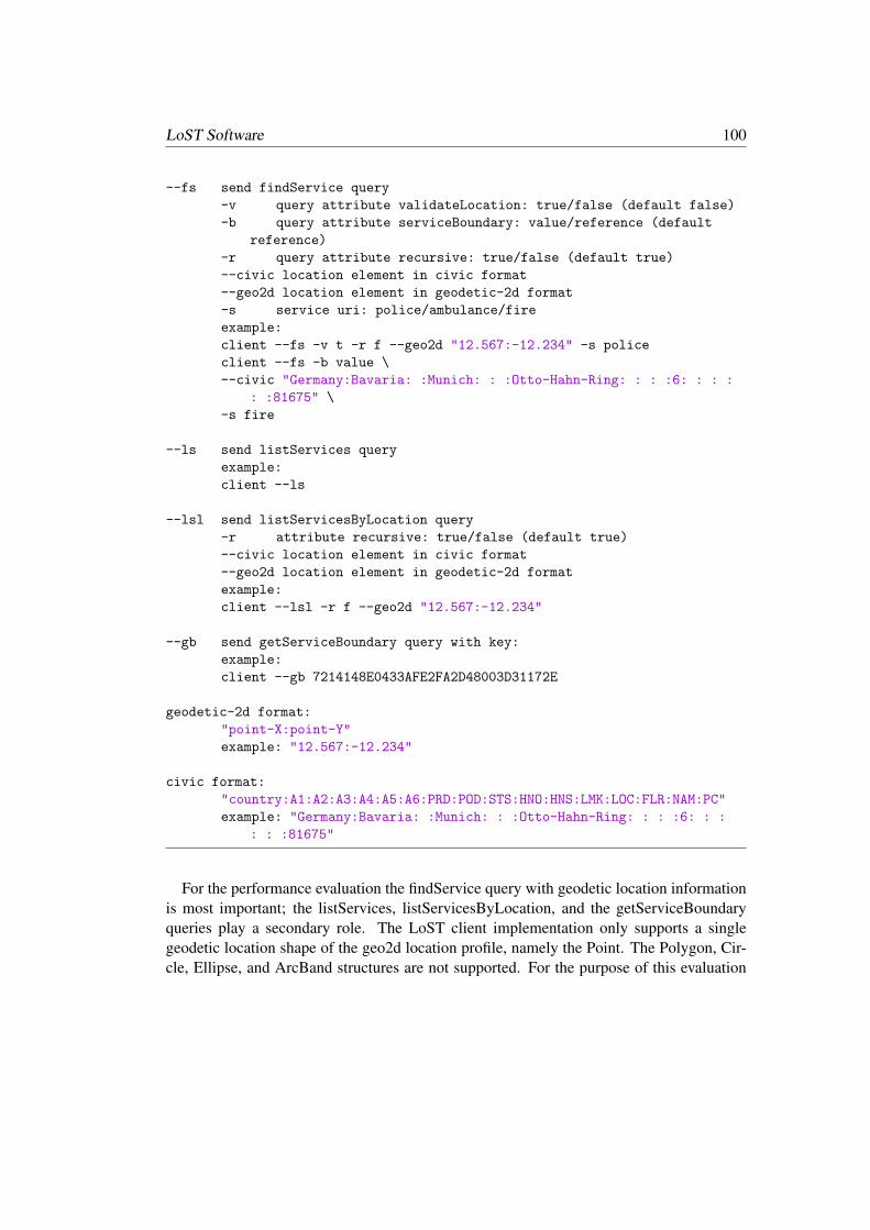
LoST Software 100
--fs send findService query
-v query attribute validateLocation: true/false (default false)
-b query attribute serviceBoundary: value/reference (default
reference)
-r query attribute recursive: true/false (default true)
--civic location element in civic format
--geo2d location element in geodetic-2d format
-s service uri: police/ambulance/fire
example:
client --fs -v t -r f --geo2d "12.567:-12.234" -s police
client --fs -b value \
--civic "Germany:Bavaria: :Munich: : :Otto-Hahn-Ring: : : :6: : : :
: :81675" \
-s fire
--ls send listServices query
example:
client --ls
--lsl send listServicesByLocation query
-r attribute recursive: true/false (default true)
--civic location element in civic format
--geo2d location element in geodetic-2d format
example:
client --lsl -r f --geo2d "12.567:-12.234"
--gb send getServiceBoundary query with key:
example:
client --gb 7214148E0433AFE2FA2D48003D31172E
geodetic-2d format:
"point-X:point-Y"
example: "12.567:-12.234"
civic format:
"country:A1:A2:A3:A4:A5:A6:PRD:POD:STS:HNO:HNS:LMK:LOC:FLR:NAM:PC"
example: "Germany:Bavaria: :Munich: : :Otto-Hahn-Ring: : : :6: : :
: : :81675"
For the performance evaluation the findService query with geodetic location informationis most important; the listServices, listServicesByLocation, and the getServiceBoundaryqueries play a secondary role. The LoST client implementation only supports a singlegeodetic location shape of the geo2d location profile, namely the Point. The Polygon, Cir-cle, Ellipse, and ArcBand structures are not supported. For the purpose of this evaluation

101 A.1. LoST Client
this is not a significant constraint given that GPS-enabled devices will mainly use the Pointlocation shape (or a circular area to express uncertainty about a point). More complex lo-cation shapes are typically the result of network-based location determination techniques,which are not used in this performance evaluation.
An example LoST client configuration is shown in Listing A.2. The LoST client needsto be configured with the IP address and port number of the LoST server. Additionally, itneeds to know the URL path, which is constructed in this example configuration using theEclipse project name and the servlet name.
Listing A.2: LoST Client Configuration ExampleserverLoST=127.0.0.1
page=/LoSTAppRoot/StartServlet
port=8080
An example findService query with geodetic location information is shown in ListingA.3. The query instructs the LoST Server to use the police service URN to request a serviceboundary by reference (rather than by value) and an interative query (rather than a recursivequery). The GPS coordinates for a location in Manhatten, New York are expressed as alatitude:longitude pair. This location refers to the following civic address determined viareverse geocoding: Sidewalk Clock at 200 5th Avenue, 5th Avenue, New York, NY 10035,United States of America.
Listing A.3: LoST Client CLI Query with findService Query Example./client --fs -b reference -r f --geo2d
"-81.1562038362026:40.4049754631706" -s police
The LoST client implementation is separated into several files, namely
findService findService.h and findService.c implement the findService query functionalitygetServiceBoundary getServiceBoundary.h and getServiceBoundary.c implement the
getServiceBoundary query functionalitylistServices listServices.h and listServices.c implement the listServices query functional-
itylistServicesByLocation listServicesByLocation.h and listServicesByLocation.c imple-
ment the listServicesByLocation query functionalitylocation location.h defines the data structure for civic and geodetic location information.
location.c defines function to populate the data structure.get config get config.h and get config.c implement the functionality to read the configu-
LoST Software 102
ration file.cl client cl client.h defines constants for CLI usage of the LoST client and cl client.cimplements the CLI parameter parsing. cl client.c also calls functions for LoST functionsand contains code for parsing civic information provided via the CLI.
http connection http connection.h and http connection.c implement the HTTP re-quest/response interaction. Because of the different socket interfaces on Windows andLinux-based systems the implementation varies between these two operating systems.
common common.h defines constants for debug, XML parameters, and emergency ser-vice URIs.
client client.c is contains the main() function of the LoST client CLI program.
The LoST client reads the configuration file, parses the CLI parameters and invokes thefunctions for building the respective LoST request. Then, the HTTP request is made to theLoST server. Note that the prototype uses regular HTTP for communicating with the LoSTserver. Then, the LoST client waits for the response from the LoST server, and prints theresponse message. Finally, the HTTP connection is terminated and after releasing resourcesthe LoST client program is terminated.
To build the code for the LoST client on Windows it is easiest to use Microsoft Visual Stu-dio and use the provided project files. When building the code from scratch (via MicrosoftVisual Studio) import all source and header files and use the NuGet package manager toinclude the libxml2-vc140-static-32 64 and the libapr-iconv libraries along with any de-pendencies. Additionally, the libraries wsock32.lib and libxml2.lib have to be added as anadditional dependency in the linker configuration. Note that the lost client.conf must be inthe same directory from which you run the LoST client executable.
A.2. LoST Server
The LoST server implementation is more complex than the client-side because it has toconnect to a database to store service boundaries. The LoST server is implemented in Javaand to run the Java application a Tomcat server is used. As a database PostgreSQL was se-lected because it supports geospatial functionality via the PostGIS extension. For softwaredevelopment Eclipse was used as an open source integrated development environment. Toexecute the LoST server the Java SE Development Kit has to be installed and for develop-ment the Java Development Kit (JDK). The implementation relies on the third party XMLlibrary JDOM2, which provides a Java-based implementation for accessing, manipulating,and outputting XML data. JDOMs SAXBuilder class can also be used as an XML parser.

103 A.2. LoST Server
On Windows it is easiest to install PostgreSQL as part of the EnterpriseDB softwarefrom https://www.enterprisedb.com, which is a pre-bundled version of the neces-sary software to run PostgreSQL. The “StackBuilder” utility is then used to install thePostGIS add-on. Configuring and optimizing a database system can be a challenge butPostgreSQL offers a convient tool called PgAdmin 4, which offers a graphical interfaceto connect to a database, to manipulate tables and views, and to execute queries amongmany other functions. Access to the PostgreSQL database via the Java app is accomplishedvia Java Database Connectivity (JDBC) for which a driver has to be downloaded fromhttps://jdbc.postgresql.org/download.html and added to the project settings inEclipse as an external JAR file.
The LoST server software also comes with a configuration file, similarly to the LoSTclient. It can be found in WebContent/WEB-INF/config/config.xml and an example LoSTserver configuration is shown in Listing A.4. Two different databases can be used to storecivic and geodetic location information, which is not utilized in the example configurationbecause both point to the same database server. For LoST servers different modes of oper-ations are available and can be set via the <mode> element in the config.xml file. Thesemodes are based on the roles defined in RFC 5582 [55]. The following modes can be set:
Resolver A resolver is contacted by a seeker, interacts with forest guides, and then queriesthe appropriate tree. Resolvers may cache query results but do not source authoritativemapping information.
TreeLeaf Leaf nodes are nodes without children, and only maintain mappings.TreeNode Tree nodes only maintain coverage regions. Coverage regions point to LoST
servers while mapping data points to service URLs. Hence, the difference between cover-age regions and mapping data is intentionally rather small and coverage regions are alsoimplemented as LoST-compatible shapes enclosing contiguous geographic areas or bydescriptors enumerating groups of civic locations. The primary difference is therefore towhat entities the URLs point to.
ForestGuide Forest guides facilitate coordination among trees and they keep track of thecoverage regions of all the trees for a service and a location profile. Forest guides onlyredirect to LoST mapping servers.
In the example configuration in Listing A.4 the LoST server operates in a TreeLeaf mode.The log file must be located in a writeable directory and the database indicated in the config-uration file, postgis lost in our example, must exist. More details about the database setupcan be found in Section A.3.
Listing A.4: LoST Server Configuration Example<?xml version="1.0" encoding="UTF-8"?>

LoST Software 104
<configuration>
<LoST>
<debug>true</debug>
<hostname>localhost</hostname>
<logFile>c://temp//LoST.log</logFile>
<dbCivicHostname>localhost</dbCivicHostname>
<dbCivicUsername>postgis</dbCivicUsername>
<dbCivicPassword>******</dbCivicPassword>
<dbCivicBase>postgis\_lost</dbCivicBase>
<dbLostHostname>localhost</dbLostHostname>
<dbLostUsername>postgis</dbLostUsername>
<dbLostPassword>******</dbLostPassword>
<dbLostBase>postgis\_lost</dbLostBase>
<mode>TreeLeaf</mode>
</LoST>
</configuration>
There are different ways to run server-side Java code; Java servlets is the technique uti-lized by this implementation. The LoST server implementations registers itself (via theTomcat server) on a specific IP address, port number and at a specific URL path and waitsfor incoming POST messages. The @WebServlet annotation is used to declare a servlet andin the LoST server implementation the code can be found in MainServlet.java file where theURL /StartServlet is registered. GET requests, on the other hand, will lead to an error (ac-cording to the LoST specification). An incoming LoST request will cause the LoST serverto process the request according to its configured role. The prototype implementation isnot designed for efficiency. It reads the configuration file and connects to the database withevery request instead of reading the configuration once and maintaining it in memory aswell as keeping the database connection open while the server is running. Hence, there isstill potential for performance optimization. This has to be kept in mind when consideringthe performance analysis.
The LoST server implementation is split into several Java files, which can be groupedinto four categories. These categories are (a) the main class, MainServlet.java, containingcode executed when a request is received, (b) code handling specific LoST queries, (c)code implementing functionality needed by different LoST server roles, and (d) supportfunctionality. Not relevant to this description is the test class LoSTClient.java.
The code for handling specific LoST requests can be found in the following Java classes:
FindService This class implements parsing of the findService and findServiceByLocationqueries and produces the response message. Both geodetic and civic location informationare supported.

105 A.2. LoST Server
GetServiceBoundary This class implements parsing of the getServiceBoundary request.The getServiceBoundary request contains a value in the key attribute, which is used tofind the service boundary in the cache. This code makes use of the getServiceById() andgetIdByKey() functions implemented in the Base class.
ListServices This class implements parsing of the listServices query and makes use of thedatabase access function in the Base class via the listServices method. The listServicesmethod crafts the response message from the Response class via the listServicesResponsemethod.
ListServicesByLocation This class implements the listServicesByLocation query and,similiarly to the ListServices class, it also creates the corresponding response by utilizingthe listServicesByLocation method from the Base class.
ServiceBoundary The methods in this class construct the <serviceBoundary> elementbased on civic or geodetic location information provided via parameters. For geodeticlocation information the polygon is encoded following the recommendations provided inRFC 5222 and RFC 5491. Not supported is the encoding of holes in services boundaries,as described in RFC 5964 [146]. The methods in this class, namely createGeodetic2d andcreateCivic, are used by the FindServiceResponse method of the FindService class andby the getServiceBoundary method in the GetServiceBoundary class.
The code implementing functionality needed by different LoST server roles can be foundin the following Java classes:
Resolver The Resolver class implements functionality to fetch mappings from cache, andif those are not present or outdated, then Forest Guides have to be contacted.
ForestGuide The ForestGuide class implements functionality to fetch coverage regionsfrom the database (for civic and geodetic location information) and to redirect the requestto the appropriate LoST mapping server.
TreeNode The TreeNode class implements functionality to interact with other TreeNodes or with Leaf Nodes (in an interative or recursive query style).
ParseFirst The ParseFirst class implements functionality of a TreeLeaf and contains codefor parsingf LoST requests based on the different types of requests available within theLoST specification.
The support functionality is found in the following Java classes:
Base This class is responsible for handling database access. This class does not onlyinclude code for establishing the connection to the PostgreSQL database using JavaDatabase Connectivity (JDBC) but also constructs the SQL queries needed for retrievingthe necessary information from the database. One example of an important SQL query

LoST Software 106
used by findServiceByLocation is shown in Listing A.5.Cache and CacheStruct These two classes implement cache management.CommonRequestPattern This class parses the XML document to find the <service>element.
Config This class reads the XML-based configuration file but also offers functionality forevent logging and for setting timestamps (used in logs and in LoST response messages).
ErrorContainer This class implements the error handling and generates LoST error re-sponse messages.
Response This class implements generic LoST response functionality, such as creatingthe <mapping>, the <serviceList>, <locationValidation>, and the <path> elements.
The Base class contains code to construct SQL queries and the most important SQLquery is to determine the record(s) where the emergency caller’s location is within the ser-vice boundary of a PSAP. This point-in-polygon functionality is provided by ST Intersects()provided by PostGIS. It takes two geometries and returns true if any part of those geome-tries is shared between the two. The ST AsText() function converts the location data fromthe database native binary format into a textual display format and ST GeomFromText()provides the conversion into the reverse direction. Listing A.5 shows this important codesegment.
Listing A.5: Java Code for Constructing the findServiceByLocation SQL QueryString query="SELECT id, country, a1, a2, a3, a4, a5, a6, hno, pc,
service_number, ";
query+="prd, pod, sts, hns, lmk, loc, flr, nam, display_name,
sip, ";
query+="expires, last_updated, ST_AsText(area) as area ";
query+="FROM lost_services WHERE ";
query+="ST_Intersects(area, ST_GeomFromText(’POINT("+pointX;
query+=" "+pointY+")’))";
if (service !=null)
query+=" AND ( service=’"+service+"’ OR service=’sos’)";
query+=";";
A.3. Database
The LoST server Java application issues queries against a number of tables whereby someof the tables are only used when the LoST server application operates in a specific role. Thefollowing tables are used for the different roles:

107 A.3. Database
Resolver The Resolver uses the resolver cache and forest guides tables. The former tableis used for caching LoST responses while the latter table is used to obtain the list of LoSTForest Guides.
TreeLeaf The TreeLeave uses the lost services and key cache tables. The lost servicestable is used to store authoritative mapping information. The key cache table is used tostore service boundary information when those are accessed by reference rather than byvalue.
TreeNode The TreeNode uses the tree children civic and tree children geodetic tables.These two tables are used to store coverage areas for civic and geodetic location informa-tion, respectively.
ForestGuide The Forest Guide uses the tree roots civic and tree roots geodetic tables.These two tables again store coverage areas.
Figure A.1 shows the database design with the tables graphically.

LoST Software 108
key_cache key db_id last_update
lost_services id country a1 a2 a3 a4 a5 a6 prd pod sts hno hns lmk loc flr nam pc service service_number sip xmpp tel display_name area a0 expires last_updated
resolver_cache request response expires
forest_guides forest_guide
tree_roots_civic country a1 a2 a3 resource
tree_roots_geodetic xy resource
tree_children_civic country a1 a2 a3 resource a4 a5 a6
tree_children_geodetic xy resource nr
Figure A.1.: Database Design.
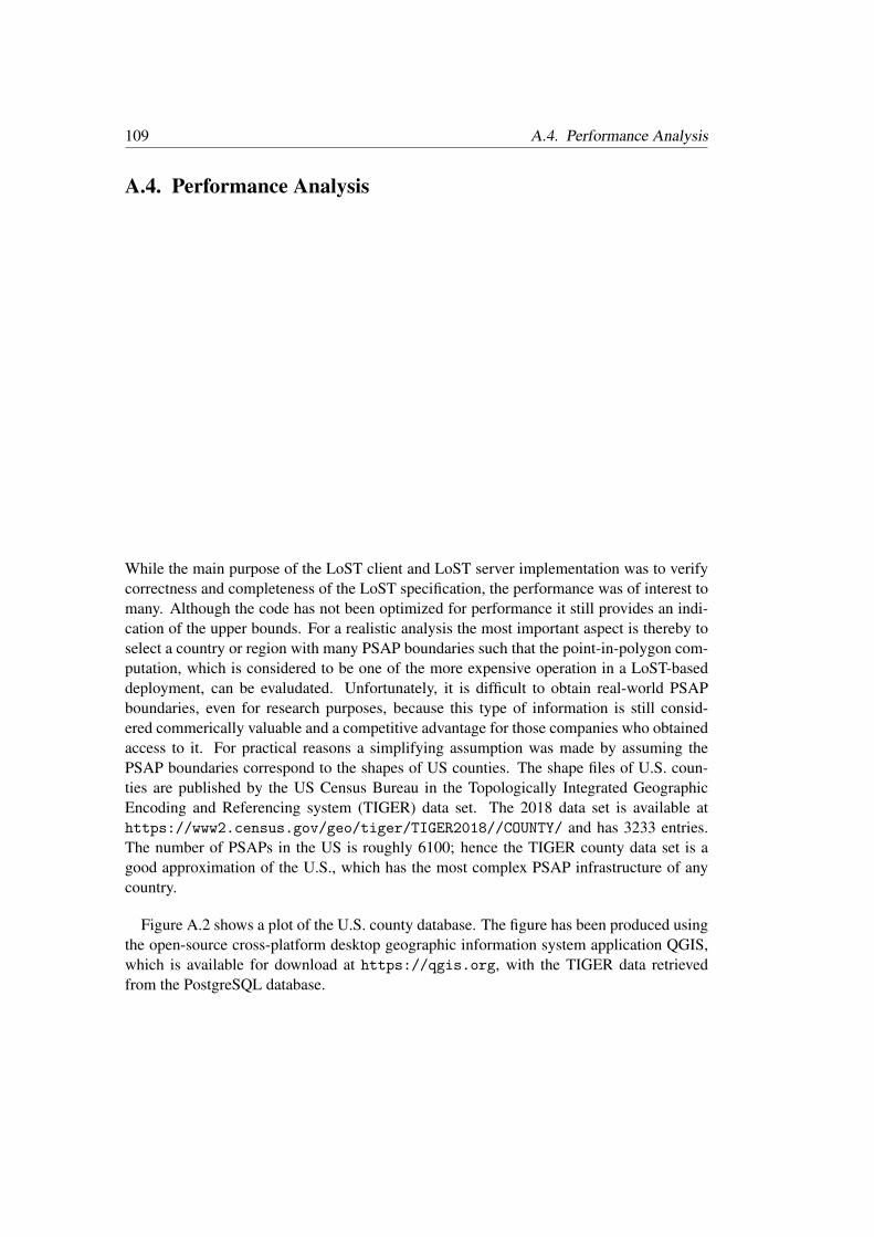
109 A.4. Performance Analysis
A.4. Performance Analysis
While the main purpose of the LoST client and LoST server implementation was to verifycorrectness and completeness of the LoST specification, the performance was of interest tomany. Although the code has not been optimized for performance it still provides an indi-cation of the upper bounds. For a realistic analysis the most important aspect is thereby toselect a country or region with many PSAP boundaries such that the point-in-polygon com-putation, which is considered to be one of the more expensive operation in a LoST-baseddeployment, can be evaludated. Unfortunately, it is difficult to obtain real-world PSAPboundaries, even for research purposes, because this type of information is still consid-ered commerically valuable and a competitive advantage for those companies who obtainedaccess to it. For practical reasons a simplifying assumption was made by assuming thePSAP boundaries correspond to the shapes of US counties. The shape files of U.S. coun-ties are published by the US Census Bureau in the Topologically Integrated GeographicEncoding and Referencing system (TIGER) data set. The 2018 data set is available athttps://www2.census.gov/geo/tiger/TIGER2018//COUNTY/ and has 3233 entries.The number of PSAPs in the US is roughly 6100; hence the TIGER county data set is agood approximation of the U.S., which has the most complex PSAP infrastructure of anycountry.
Figure A.2 shows a plot of the U.S. county database. The figure has been produced usingthe open-source cross-platform desktop geographic information system application QGIS,which is available for download at https://qgis.org, with the TIGER data retrievedfrom the PostgreSQL database.

LoST Software 110
Figure A.2.: Plot of the U.S. TIGER County Dataset (2018).

111 A.4. Performance Analysis
The TIGER data set is available in shapefiles, which cannot be imported directly into thePostgres database via the pgAdmin backup/restore tool. There are two techniques that canbe used for importing the data set. First, it is possible to use the external PostGIS ShapefileImport/Export Manager tool. This tool can import the *.shp files found in the downloadedZIP archives. Second, an automated, but considerable more complex, procedure for down-loading and importing the TIGER data set is available in form of scripts. The latter approachuses the psql and the shp2pgsql command line tools. The next few paragraphs explain theautomated data download and importing.
Assuming that the database has already been configured to use the extensions for post-gis, fuzzystrmatch, postgis tiger geocoder, and address standardizer the first step is touse the pgAdmin utility to configure the paths to various programs. This is, unsurpris-ingly, accomplished by modifying values in a specific field in the loader platform and theloader variables tables. It is easiest to use the pgAdmin utility to select these two tablesin the tiger schema. By using the “View/Edit Data” function on the two tables showing allrows displays the current values. The values set for the declare sect column have been setto the values in Listing A.6 on my system, which will have to be adjusted to each systemdepending on the US and the location of the binaries.
Listing A.6: Configuration Settings for the Loader Tablesset TMPDIR=F:\LoST\gisdata\temp\
set UNZIPTOOL="C:\Program Files\7-Zip\7z.exe"
set WGETTOOL="F:\Program Files (x86)\GnuWin32\bin\wget.exe"
set PGBIN=F:\Program Files\PostgreSQL\11\bin
set PGPORT=5432
set PGHOST=localhost
set PGUSER=postgres
set PGPASSWORD=<<password goes in here>>
set PGDATABASE=postgis_lost
set PSQL="F:\Program Files\PostgreSQL\11\bin\psql.exe"
set SHP2PGSQL="F:\Program Files\PostgreSQL\11\bin\shp2pgsql.exe"
Once this configuration data has been saved, the configuration can be used to create ascript, which will subsequently be used to perform the download and import. The commandline to execute this script is shown in Listing A.7. The semantics of the command lineparameters are described in the manual, which is available at https://www.postgresql.org/docs/current/app-psql.html.
Listing A.7: Command line to generate the so-called Nation-ScriptF:\LoST\gisdata>psql -U postgres -c "SELECT
Loader_Generate_Nation_Script(’windows’)" -d postgis_lost -tA >

LoST Software 112
nation_script_load.bat
After successfully generating the nation script load.bat it can be executed as shown inListing A.8.
Listing A.8: Running the Nation-Script FileF:\LoST\gisdata>nation_script_load.bat
After a successful execution the data is imported into the indicated database and thecorrectness can be verified by counting the rows in the county and state tables. The rows inthe county database should be 3233 and the number of rows in the state table should be 56.
Note that the same technique can be used to retrieve additional data from the TIGERdatabase to perform geocoding and reverse geocoding. Reverse geocoding is used to re-solve a geodetic location into a civic address and geocoding performs the opposite. Thecommands shown in Listing A.9 are necessary to download and import detailed civic infor-mation of all states. Note, however, that the download of the detailed data will take bothtime (potentially in the order of days) and harddisk space.
Listing A.9: Running the State-Script FileF:\LoST\gisdata>psql -U postgres -c "SELECT
Loader_Generate_Script(ARRAY[’AK’, ’AL’, ’AR’, ’AZ’, ’CA’, ’CO’, ’CT’,
’DC’, ’DE’, ’FL’, ’GA’, ’HI’, ’IA’, ’ID’, ’IL’, ’IN’, ’KS’, ’KY’, ’LA’,
’MA’, ’MD’, ’ME’, ’MI’, ’MN’, ’MO’, ’MS’, ’MT’, ’NC’, ’ND’, ’NE’, ’NH’,
’NJ’, ’NM’, ’NV’, ’NY’, ’OH’, ’OK’, ’OR’, ’PA’, ’RI’, ’SC’, ’SD’, ’TN’,
’TX’, ’UT’, ’VA’, ’VT’, ’WA’, ’WI’, ’WV’, ’WY’], ’windows’)" -d
postgis_lost -tA > F:\LoST\gisdata\state_script_load.bat
F:\LoST\gisdata>state_script_load.bat
The database structure used by the TIGER imported data, of course, does not correspondto the structure the LoST server database uses. Hence, it is necessary to import relevantinformation from the TIGER database into the LoST database. Figure A.3 shows 10 rowsadded to the LoST database.

113 A.4. Performance Analysis
Figure A.3.: Example data to be inserted in LoST Database.
The SQL query in Listing A.11 has been used to add the data shown in Figure A.3 to theLoST database. Before it can be run, a separate table was created to perform a mappingbetween the abbreviations of state names with the numerical values used in the TIGER dataset. The SQL script used for the import is shown in Listing A.10. While it is not striclynecessary to perform such a mapping, the use of state name abbreviations (such as ‘CA’for California) greatly improves readability of the results and enables easier debugging formatching LoST requests against records in the database.
Listing A.10: SQL Code for Creating State Name Abbreviation MappingDROP TABLE IF EXISTS statefp_to_name;
CREATE TABLE statefp_to_name (
state_abbr char(2),
statefp char(2) PRIMARY KEY,
state_name character varying
);
INSERT INTO statefp_to_name (state_abbr,statefp,state_name)
VALUES
(’AK’,2,’ALASKA’),
(’AL’,1,’ALABAMA’),
(’AR’,5,’ARKANSAS’),
(’AS’,60,’AMERICAN SAMOA’),
(’AZ’,4,’ARIZONA’),
(’CA’,6,’CALIFORNIA’),
(’CO’,8,’COLORADO’),
(’CT’,9,’CONNECTICUT’),
(’DC’,11,’DISTRICT OF COLUMBIA’),
(’DE’,10,’DELAWARE’),
(’FL’,12,’FLORIDA’),
(’GA’,13,’GEORGIA’),
(’GU’,66,’GUAM’),
(’HI’,15,’HAWAII’),
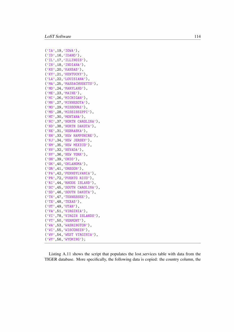
LoST Software 114
(’IA’,19,’IOWA’),
(’ID’,16,’IDAHO’),
(’IL’,17,’ILLINOIS’),
(’IN’,18,’INDIANA’),
(’KS’,20,’KANSAS’),
(’KY’,21,’KENTUCKY’),
(’LA’,22,’LOUISIANA’),
(’MA’,25,’MASSACHUSETTS’),
(’MD’,24,’MARYLAND’),
(’ME’,23,’MAINE’),
(’MI’,26,’MICHIGAN’),
(’MN’,27,’MINNESOTA’),
(’MO’,29,’MISSOURI’),
(’MS’,28,’MISSISSIPPI’),
(’MT’,30,’MONTANA’),
(’NC’,37,’NORTH CAROLINA’),
(’ND’,38,’NORTH DAKOTA’),
(’NE’,31,’NEBRASKA’),
(’NH’,33,’NEW HAMPSHIRE’),
(’NJ’,34,’NEW JERSEY’),
(’NM’,35,’NEW MEXICO’),
(’NV’,32,’NEVADA’),
(’NY’,36,’NEW YORK’),
(’OH’,39,’OHIO’),
(’OK’,40,’OKLAHOMA’),
(’OR’,41,’OREGON’),
(’PA’,42,’PENNSYLVANIA’),
(’PR’,72,’PUERTO RICO’),
(’RI’,44,’RHODE ISLAND’),
(’SC’,45,’SOUTH CAROLINA’),
(’SD’,46,’SOUTH DAKOTA’),
(’TN’,47,’TENNESSEE’),
(’TX’,48,’TEXAS’),
(’UT’,49,’UTAH’),
(’VA’,51,’VIRGINIA’),
(’VI’,78,’VIRGIN ISLANDS’),
(’VT’,50,’VERMONT’),
(’WA’,53,’WASHINGTON’),
(’WI’,55,’WISCONSIN’),
(’WV’,54,’WEST VIRGINIA’),
(’WY’,56,’WYOMING’);
Listing A.11 shows the script that populates the lost services table with data from theTIGER database. More specifically, the following data is copied: the country column, the

115 A.4. Performance Analysis
A1 column (used for the top-level subdivision within a country, i.e. the state in the US),A2 column (used for the political district; the county in the US), the service number col-umn (which is set to 911 in the US), the service column (which uses the ‘sos’ service inthe example only), the sip column (which is the PSAP URI to be used by the seeker forreaching out to a PSAP call taker over SIP), and the area column used to encode the ser-vice boundary. Note that the area column contains the polygon information encoded in acustom, PostgreSQL-specific binary format rather than the textual, GML-based representa-tion shown earlier in LoST requests and responses. This is primarily done for performancereasons.
Listing A.11: SQL Script for Importing the TIGER Data into the LoST DatabaseINSERT INTO lost_services (country, a1, a2, display_name, service_number,
service, sip, area)
SELECT ’US’ as country, s.state_abbr as a1, t.namelsad as a2, (’US - ’ ||
s.state_abbr || ’ - ’ || t.namelsad || ’- 911 SOS’)::varchar as
display_name, ’911’ as service_number, ’sos’ as service, ((’sip:sos@’
|| regexp_replace(lower(t.name), ’[ ]’,E’_’) ||
’.example.com’))::varchar as sip, t.geom as area
FROM tl_2018_us_county as t INNER JOIN statefp_to_name s ON t.statefp =
s.statefp
It is also useful to set the expires and last updated fields of the records for correct opera-tion of the LoST server application. Listing A.12 shows the SQL code.
Listing A.12: SQL Script for updating expires and last updatedUPDATE lost_services
SET expires = ’2020-12-31T23:59:59Z,2007-03-05T15:08:00Z’
WHERE expires is NULL;
UPDATE lost_services
SET last_updated = ’2019-05-31T23:59:59Z,2007-03-05T15:08:00Z’
WHERE last_updated is NULL;
Once the example data is available in the LoST database, the next step is to constructexample queries that will be used by the seeker against the LoST server. There have to beenough example queries to ensure that any anomalies caused by OS process scheduling,delay variation between the LoST Java application running on the Tomcat server and thePostgreSQL database, and varying latency on the network connection are averaged out.Additionally, the queries have to contain points somewhere in the US and cover all thecounties. Furthermore, the location provided in two consecutive queries should not referto locations directly next to each other to avoid any geolocation caching capabilities by
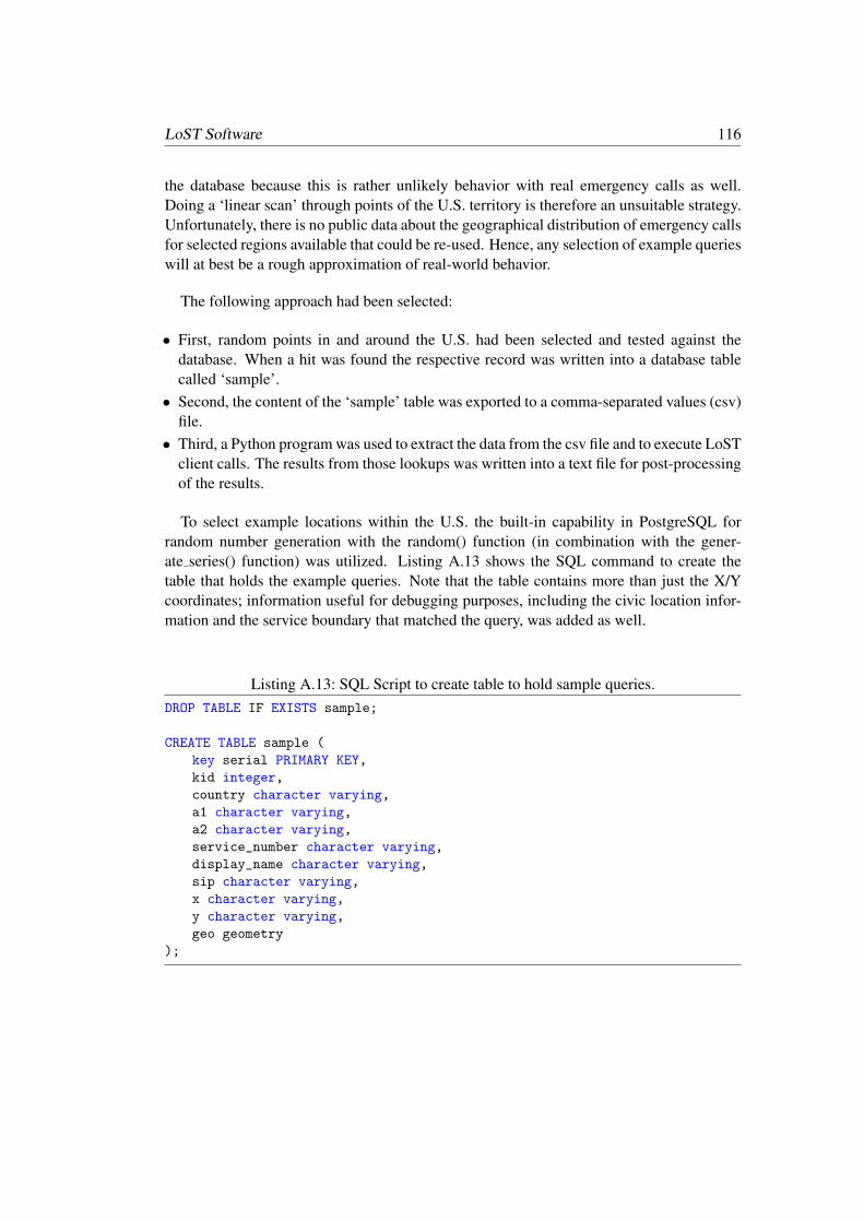
LoST Software 116
the database because this is rather unlikely behavior with real emergency calls as well.Doing a ‘linear scan’ through points of the U.S. territory is therefore an unsuitable strategy.Unfortunately, there is no public data about the geographical distribution of emergency callsfor selected regions available that could be re-used. Hence, any selection of example querieswill at best be a rough approximation of real-world behavior.
The following approach had been selected:
• First, random points in and around the U.S. had been selected and tested against thedatabase. When a hit was found the respective record was written into a database tablecalled ‘sample’.
• Second, the content of the ‘sample’ table was exported to a comma-separated values (csv)file.
• Third, a Python program was used to extract the data from the csv file and to execute LoSTclient calls. The results from those lookups was written into a text file for post-processingof the results.
To select example locations within the U.S. the built-in capability in PostgreSQL forrandom number generation with the random() function (in combination with the gener-ate series() function) was utilized. Listing A.13 shows the SQL command to create thetable that holds the example queries. Note that the table contains more than just the X/Ycoordinates; information useful for debugging purposes, including the civic location infor-mation and the service boundary that matched the query, was added as well.
Listing A.13: SQL Script to create table to hold sample queries.DROP TABLE IF EXISTS sample;
CREATE TABLE sample (
key serial PRIMARY KEY,
kid integer,
country character varying,
a1 character varying,
a2 character varying,
service_number character varying,
display_name character varying,
sip character varying,
x character varying,
y character varying,
geo geometry
);

117 A.4. Performance Analysis
An SQL query covering the region of all U.S. counties, as shown in Listing A.14, is usedto generate example queries, which are inserted into the ‘sample’ table.
Listing A.14: SQL Script to create sample queries.-- lat: from -179 to +180
-- lon: from +70 to -15
WITH
numbers AS
(
SELECT random() * 361-180 as x, random() * 87-16 as y
FROM generate_series(1, 50000000)
),
input_data AS
(
SELECT ST_GeomFromText(CONCAT_WS (’ ’, ’POINT(’, CAST (n.x AS text),
CAST (n.y AS text), ’)’)) as geo, n.x, n.y
FROM numbers as n
)
INSERT INTO sample(kid, country, a1, a2, service_number, display_name,
sip, x, y, geo)
SELECT l.id, l.country, l.a1, l.a2, l.service_number, l.display_name,
l.sip, n.x, n.y, n.geo
FROM input_data as n CROSS JOIN lost_services as l
WHERE ST_Intersects(l.area, n.geo)
ORDER BY l.country, l.a1;
When identifying a region from which random x/y coordinates are chosen it is useful toverify whether the expression is indeed correct. This can be accomplished by the SQL queryshown in Listing A.15 where we use the min() and max() functions to determine whetherthe generated random values are indeed within the +70 to -15 range.
Listing A.15: Verifying correctness of the generated data.SELECT min(i), max(i) FROM (
SELECT trunc(random()*((72)+15)-16) AS i FROM generate_series(1,1000000)
) q;
Plotting the example queries using the QGIS application, see Figure A.4, shows whetherthe sample queries have been correctly created and whether the entire region of the U.S. hasbeen covered by the example queries.

LoST Software 118
Figure A.4.: Plot of example queries.

119 A.4. Performance Analysis
Next, we have to export the content of the ‘sample’ table to an csv file, which will beused for post-processing next. Listing A.16 shows the export commands.
Listing A.16: Exporting the example queries into a CSV file.>psql -h localhost -U postgres -d postgis_lost
> postgis_lost=# \COPY (SELECT * FROM sample) TO ’example_queries.csv’
(format csv, delimiter ’;’)
A small section of the CSV file is shown in Figure A.5. The most important data is incolumn 8 and 9 representing the X and Y coordinates of the query to be used.
Figure A.5.: CSV file with example queries.
Next, the example queries.csv is used as input to the Python script shown in List-ing A.17. This short Python script reads each line of the CSV file and executes theLoST client program with the X and Y coordinates as command line parameters. TheLoST client program has been compiled with the TIME MEASUREMENT and theTIME MEASUREMENT SUMMARY C pre-processor directives enabled to producetiming data. This timing data is written to a log file for final processing, which containsthree data points: the size of the LoST request (in bytes), the size of the LoST response(in bytes), and the execution time (in msec). The execution time includes processing thecommand line parameters to construct the LoST query until the time when the response hasbeen received.
Listing A.17: Python Script to parse CSV file and execute LoST queries.import csv
import subprocess

LoST Software 120
with open(’example_queries.csv’) as csv_file:
csv_reader = csv.reader(csv_file, delimiter=’;’)
line_count = 0
for row in csv_reader:
result = subprocess.run([’client’,’--fs -b reference -r f --geo2d
\"{row[8]}:{row[9]}\" -s police’],stdout=subprocess.PIP)
line_count += 1
print(f’Processed {line_count} lines.’)
For this performance measurement the following assumptions were made:
• No TLS is used in this test setup. The overhead of TLS as a communication security solu-tion is described in other parts of this thesis and, once the handshake has been completed,the overhead for symmetric key cryptography is minimal.
• Only geodetic location information is used because civic location lookups are much fasterdatabase operations and do not even require special extensions to database systems.
• Only a single location shape (namely a point) is used in queries because the data providedby the end device is supposed to be obtained via a GPS. Other location shapes, suchas circles (which are able to express uncertainty) or arc bands (which are typically usedin context of network-based location determination techniques) are not explored in thisperformance investigation.
• Caching capabilies are not explored in this performance analysis. The use of caching (byresolves as well as by seekers) would improve performance in a real-world scenario.
• Service boundares are transmitted by reference and subsequently not dereferenced. Thisleads to smaller messages transmitted over the wire and obtaining service boundariesis only useful when caching is utilized. Note also that the support for holes in serviceboundaries, as described in RFC 5964, is not implemented in this prototype.
• To reduce the impact of network latency all components, i.e. LoST clients executedsequentially from the Python script, LoST server as a Java application on the Tomcatserver, and PostgreSQL database) were executed on the same machine.
For the test setup an Intel Xeon CPU E3-1231 v3 @ 3.40 GHz with 4 cores and 8 threads,with 16 GB of RAM and 8 MB cache running Windows 10 Home in version 10.0.18362 wasused. On the software side PgAdmin 4 in version 4.5 was used with PostgreSQL version11.2 as well as Tomcat 9.0.19.
Figure A.6 shows the plot of the 550,000 query/response measurements graphically. Theminimal roundtrip time (RTT) of the LoST request/response is 39 msec and the maximumis 856 msec. The median is 55 msec and the mean is 72.17 msec. The first and third quartileis 48 msec and 65 msec, respectively.

121 A.4. Performance Analysis
Figure A.6.: Roundtrip Time of findService Request/Response.
LoST Software 122
As a conclusion, without special optimizations at the LoST server application nor at thedatabase itself, without the use of caching at resolvers and seekers the RTT of a LoSTinteraction with a dataset taking the most complex PSAP infrastructure of any country intoaccount the use of LoST at the end device is not only feasible but also possible withoutcreating unnecessary delay in an emergency services situation.
Bibliography
[1] NENA. National Emergency Number Association (NENA). URL: http://www.nena.org.
[2] S. L. Keoh, S. S. Kumar, and H. Tschofenig. Securing the internet of things: Astandardization perspective. IEEE Internet of Things Journal, 1(3):265–275, June2014.
[3] H. Tschofenig and E. Baccelli. Cyberphysical security for the masses: A surveyof the internet protocol suite for internet of things security. IEEE Security Privacy,17(5):47–57, Sep. 2019.
[4] K. Zandberg, K. Schleiser, F. Acosta, H. Tschofenig, and E. Baccelli. Securefirmware updates for constrained iot devices using open standards: A reality check.IEEE Access, PP:1–1, 05 2019.
[5] H. Schulzrinne and R. Marshall. Requirements for Emergency Context Resolutionwith Internet Technologies. RFC 5012, Internet Engineering Task Force, January2008.
[6] J. Peterson. A Presence-based GEOPRIV Location Object Format. RFC 4119, Inter-net Engineering Task Force, December 2005.
[7] H. Schulzrinne, H. Tschofenig, C. Holmberg, and M. Patel. Public Safety AnsweringPoint (PSAP) Callback. RFC 7090, Internet Engineering Task Force, April 2014.
[8] H. Schulzrinne, S. McCann, G. Bajko, H. Tschofenig, and D. Kroeselberg. Exten-sions to the Emergency Services Architecture for Dealing With Unauthenticated andUnauthorized Devices. RFC 7406, Internet Engineering Task Force, December 2014.
[9] Randall Gellens, Brian Rosen, and Hannes Tschofenig. Next-Generation Vehicle-Initiated Emergency Calls. RFC 8148, May 2017.
[10] Brian Rosen, Henning Schulzrinne, Hannes Tschofenig, and Randall Gellens. Data-

Bibliography 124
Only Emergency Calls. Internet-Draft draft-ietf-ecrit-data-only-ea-16, Internet Engi-neering Task Force, October 2018. Work in Progress.
[11] T. Taylor, H. Tschofenig, H. Schulzrinne, and M. Shanmugam. Security Threatsand Requirements for Emergency Call Marking and Mapping. RFC 5069, InternetEngineering Task Force, January 2008.
[12] R. Marshall. Requirements for a Location-by-Reference Mechanism. RFC 5808,Internet Engineering Task Force, May 2010.
[13] H. Tschofenig and H. Schulzrinne. GEOPRIV Layer 7 Location Configuration Pro-tocol: Problem Statement and Requirements. RFC 5687, Internet Engineering TaskForce, March 2010.
[14] H. Schulzrinne, L. Liess, H. Tschofenig, B. Stark, and A. Kuett. Location Hiding:Problem Statement and Requirements. RFC 6444, Internet Engineering Task Force,January 2012.
[15] B. Rosen and J. Polk. Best Current Practice for Communications Services in Supportof Emergency Calling. RFC 6881, Internet Engineering Task Force, March 2013.
[16] Wikipedia. National Emergency Number Association (NENA), November 2018.
[17] NENA. NENA Interim VoIP Architecture for Enhanced 9-1-1 Services (i2), Standard08-001, December 2005.
[18] NENA. NENA Interim VoIP Architecture for Enhanced 9-1-1 Services (i2), Standard08-001 v2, August 2010.
[19] H. Schulzrinne and Tschofenig. Internet Protocol-based Emergency Services. Wiley,August 2013.
[20] European Commission. Standardization Mandate to the European Standards Organ-isations (ESO) in Support of the Location Enhanced Emergency Call Service, M/493EN, may 2011. URL: http://ec.europa.eu/growth/tools-databases/
mandates/index.cfm?fuseaction=select_attachments.download&doc_
id=820.
[21] ETSI. Functional architecture to support European requirements on emergencycaller location determination and transport, Final draft ETSI ES 203 178 V1.0.0,apr 2014. URL: https://www.etsi.org/deliver/etsi_es/203100_203199/203178/01.00.00_50/es_203178v010000m.pdf.

125 Bibliography
[22] ETSI. Protocol specifications for Emergency Service Caller Location de-termination and transport, Final draft ETSI ES 203 283 V1.1.0, sep2017. URL: https://www.etsi.org/deliver/etsi_es/203200_203299/
203283/01.01.00_50/es_203283v010100m.pdf.
[23] M. Thomson and R. Bellis. Location Information Server (LIS) Discovery Using IPAddresses and Reverse DNS. RFC 7216, Internet Engineering Task Force, April2014.
[24] M. Barnes. HTTP-Enabled Location Delivery (HELD). RFC 5985, Internet Engi-neering Task Force, September 2010.
[25] J. Winterbottom, M. Thomson, H. Tschofenig, and R. Barnes. Use of Device Identityin HTTP-Enabled Location Delivery (HELD). RFC 6155, Internet Engineering TaskForce, March 2011.
[26] R. Bellis. Flow Identity Extension for HTTP-Enabled Location Delivery (HELD).RFC 6915, Internet Engineering Task Force, April 2013.
[27] J. Winterbottom, H. Tschofenig, and L. Liess. A routing request extension for thehttp-enabled location delivery (held) protocol. RFC 7840, RFC Editor, May 2016.
[28] H. Tschofenig, S. Decugis, J. Mahoney, and J. Korhonen. Diameter: New GenerationAAA Protocol - Design, Practice, and Applications. Wiley, June 2019.
[29] ETSI. Network Technologies (NTECH); Network Attachment; e2 inter-face based on the DIAMETER protocol, ETSI ES 283 035 V3.2.1, jan2018. URL: https://www.etsi.org/deliver/etsi_es/283000_283099/
283035/03.02.01_60/es_283035v030201p.pdf.
[30] H. Schulzrinne. Dynamic Host Configuration Protocol (DHCPv4 and DHCPv6) Op-tion for Civic Addresses Configuration Information. RFC 4776, Internet EngineeringTask Force, November 2006.
[31] J. Polk, J. Schnizlein, and M. Linsner. Dynamic Host Configuration Protocol Op-tion for Coordinate-based Location Configuration Information. RFC 3825, InternetEngineering Task Force, July 2004.
[32] B. Rosen. Emergency Call Information in the Domain Name System, October 2005.draft-rosen-dns-sos-03.txt (expired), Internet Engineering Task Force.
[33] M. Mealling. Dynamic Delegation Discovery System (DDDS) Part One: The Com-

Bibliography 126
prehensive DDDS. RFC 3401, Internet Engineering Task Force, October 2002.
[34] M. Mealling. Dynamic Delegation Discovery System (DDDS) Part Two: The Algo-rithm. RFC 3402, Internet Engineering Task Force, October 2002.
[35] M. Mealling. Dynamic Delegation Discovery System (DDDS) Part Three: The Do-main Name System (DNS) Database. RFC 3403, Internet Engineering Task Force,October 2002.
[36] M. Mealling. Dynamic Delegation Discovery System (DDDS) Part Four: The Uni-form Resource Identifiers (URI). RFC 3404, Internet Engineering Task Force, Octo-ber 2002.
[37] J. Peterson, O. Kolkman, H. Tschofenig, and B. Aboba. Architectural Considerationson Application Features in the DNS. RFC 6950, Internet Engineering Task Force,October 2013.
[38] K. Wolf and A. Mayrhofer. Considerations for Civic Addresses in the Presence In-formation Data Format Location Object (PIDF-LO): Guidelines and IANA RegistryDefinition. RFC 5774, Internet Engineering Task Force, March 2010.
[39] J. Winterbottom, M. Thomson, R. Barnes, B. Rosen, and R. George. SpecifyingCivic Address Extensions in the Presence Information Data Format Location Object(PIDF-LO). RFC 6848, Internet Engineering Task Force, January 2013.
[40] J. Winterbottom, M. Thomson, and H. Tschofenig. GEOPRIV Presence InformationData Format Location Object (PIDF-LO) Usage Clarification, Considerations, andRecommendations. RFC 5491, Internet Engineering Task Force, March 2009.
[41] H. Schulzrinne and B. Rosen. Emergency Services for Internet Telephony Systems,October 2004. draft-schulzrinne-sipping-emergency-arch-02.txt (expired), InternetEngineering Task Force.
[42] H. Schulzrinne. A Uniform Resource Name (URN) for Emergency and Other Well-Known Services. RFC 5031, Internet Engineering Task Force, January 2008.
[43] H. Alvestrand. Overview: Real Time Protocols for Browser-based Applications.Internet-Draft draft-ietf-rtcweb-overview-19, Internet Engineering Task Force, 112017. Work in progress.
[44] P. Saint-Andre. Extensible Messaging and Presence Protocol (XMPP): Core. RFC6120, Internet Engineering Task Force, March 2011.

127 Bibliography
[45] B. Carpenter. Architectural Principles of the Internet. RFC 1958, Internet Engineer-ing Task Force, June 1996.
[46] H. Tschofenig, B. Aboba, J. Peterson, and D. McPherson. Trends in Web Appli-cations and the Implications on Standardization, May 2012. draft-tschofenig-post-standardization-02 (expired), Internet Engineering Task Force.
[47] EENA. Public Safety Answering Points Global Edition, December 2018. URL:https://eena.org/wp-content/uploads/2018-12-19_Abstract_Light.
pdf (last accessed: Nov. 2019).
[48] Gary Machado. NG112 Transition Models - Implementation Activi-ties, Version 2.0, July 2015. URL: https://eena.org/document/
ng112-transition-models-implementation-activities/ (last accessed:Nov. 2019).
[49] EENA. PSAP Directory: Supporting Inter-PSAP Communication Across NationalBorder, June 2019. URL: https://eena.org/document/psap-directory/ (lastaccessed: Nov. 2019).
[50] EENA. EENA Operations Document - Overload of calls, December 2012. URL:https://eena.org/document/overload-of-calls/, (last accessed: Nov.2019).
[51] H. Schulzrinne and H. Tschofenig. Elements Based on the Location-to-ServiceTranslation (LoST) Protocol. RFC 6739, Internet Engineering Task Force, October2012.
[52] T. Hardie, A. Newton, H. Schulzrinne, and H. Tschofenig. LoST: A Location-to-Service Translation Protocol. RFC 5222, Internet Engineering Task Force, August2008.
[53] C. Jennings, J. Peterson, and M. Watson. Private Extensions to the Session InitiationProtocol (SIP) for Asserted Identity within Trusted Networks. RFC 3325, InternetEngineering Task Force, November 2002.
[54] H. Tschofenig, H. Schulzrinne, and B. Aboba. Trustworthy Location. RFC 7378,Internet Engineering Task Force, December 2014.
[55] H. Schulzrinne. Location-to-URL Mapping Architecture and Framework. RFC 5582,Internet Engineering Task Force, September 2009.

Bibliography 128
[56] H. Schulzrinne, J. Polk, and H. Tschofenig. Discovering Location-to-Service Trans-lation (LoST) Servers Using the Dynamic Host Configuration Protocol (DHCP).RFC 5223, Internet Engineering Task Force, August 2008.
[57] B. Rosen, H. Schulzrinne, J. Polk, and A. Newton. Framework for Emergency Call-ing Using Internet Multimedia. RFC 6443, Internet Engineering Task Force, Decem-ber 2011.
[58] B. Rosen. Dial String Parameter for the Session Initiation Protocol Uniform ResourceIdentifier. RFC 4967, Internet Engineering Task Force, July 2007.
[59] H. Schulzrinne. The tel URI for Telephone Numbers. RFC 3966, Internet Engineer-ing Task Force, December 2004.
[60] M. Thomson and J. Winterbottom. Discovering the Local Location InformationServer (LIS). RFC 5986, Internet Engineering Task Force, September 2010.
[61] R. Barnes, M. Thomson, J. Winterbottom, and H. Tschofenig. Location Configura-tion Extensions for Policy Management. RFC 7199, Internet Engineering Task Force,April 2014.
[62] REACH112. REsponding to All Citizens needing Help (REACH112) Project. URL:https://eena.org/eu-projects/reach-112/.
[63] R. Gellens and H. Tschofenig. Next-generation pan-european ecall. RFC 8147, RFCEditor, May 2017.
[64] R. Gellens, B. Rosen, H. Tschofenig, R. Marshall, and J. Winterbottom. Additionaldata related to an emergency call. RFC 7852, RFC Editor, July 2016.
[65] R. Barnes, M. Lepinski, A. Cooper, J. Morris, H. Tschofenig, and H. Schulzrinne.An Architecture for Location and Location Privacy in Internet Applications. RFC6280, Internet Engineering Task Force, July 2011.
[66] J. Rosenberg, H. Schulzrinne, G. Camarillo, A. Johnston, J. Peterson, R. Sparks,M. Handley, and E. Schooler. SIP: Session Initiation Protocol. RFC 3261, InternetEngineering Task Force, June 2002.
[67] J. Polk, B. Rosen, and J. Peterson. Location Conveyance for the Session InitiationProtocol. RFC 6442, Internet Engineering Task Force, December 2011.
[68] Wikipedia. ’Swatting’, November 2019. URL: https://en.wikipedia.org/

129 Bibliography
wiki/Swatting.
[69] EENA. False Emergency Calls, EENA Operations Document, Version 1.1, May 2011.URL: https://eena.org/document/false-emergency-calls/ (last accessed:Nov. 2019).
[70] H. Schulzrinne and J. Polk. Communications Resource Priority for the Session Initi-ation Protocol (SIP). RFC 4412, Internet Engineering Task Force, February 2006.
[71] L. Daigle and A. Newton. Domain-Based Application Service Location Using SRVRRs and the Dynamic Delegation Discovery Service (DDDS). RFC 3958, InternetEngineering Task Force, January 2005.
[72] P. Saint-Andre and J. Hodges. Representation and Verification of Domain-BasedApplication Service Identity within Internet Public Key Infrastructure Using X.509(PKIX) Certificates in the Context of Transport Layer Security (TLS). RFC 6125,Internet Engineering Task Force, March 2011.
[73] D. Atkins and R. Austein. Threat Analysis of the Domain Name System (DNS). RFC3833, Internet Engineering Task Force, August 2004.
[74] C. Rigney, S. Willens, A. Rubens, and W. Simpson. Remote Authentication Dial InUser Service (RADIUS). RFC 2865, Internet Engineering Task Force, June 2000.
[75] V. Fajardo, J. Arkko, J. Loughney, and G. Zorn. Diameter Base Protocol. RFC 6733,Internet Engineering Task Force, October 2012.
[76] M. Thomson and J. Winterbottom. Using Device-Provided Location-Related Mea-surements in Location Configuration Protocols. RFC 7105, Internet EngineeringTask Force, January 2014.
[77] J. Peterson, H. Schulzrinne, and H. Tschofenig. Secure Telephone Identity ProblemStatement and Requirements. RFC 7340, Internet Engineering Task Force, Septem-ber 2014.
[78] C. Mayville. 911 Swatters Cost Thousands, Endanger Lives,February 2009. URL: http://www.govtech.com/security/
911-Swatters-Cost-Thousands-Endanger-Lives.html.
[79] FBI. Don’t Make the Call - The New Phenomenon of ’Swatting’, February2008. URL: https://archives.fbi.gov/archives/news/stories/2008/
february/swatting020408, (last accessed: Nov. 2019).

Bibliography 130
[80] Lucian Constantin. Vulnerability in embedded Web server exposes millions of routersto hacking, December 2014. URL: https://bit.ly/2RetduE.
[81] Lucian Constantin. At least 700K routers given to customers by ISPs can be hacked,March 2015. URL: http://www.computerworld.com/article/2899663/
at-least-700k-routers-given-to-customers-by-isps-can-be-hacked.
html.
[82] L. Daigle. Domain-Based Application Service Location Using URIs and the Dy-namic Delegation Discovery Service (DDDS). RFC 4848, Internet Engineering TaskForce, April 2007.
[83] B. Aboba, L. Blunk, J. Vollbrecht, J. Carlson, and H. Levkowetz. Extensible Authen-tication Protocol (EAP). RFC 3748, Internet Engineering Task Force, June 2004.
[84] William E. Burr, Donna F. Dodson, Elaine M. Newton, Ray A. Perlner, W. TimothyPolk, Sarbari Gupta, and Emad A. Nabbus. NIST Special Publication 800-63-3:Electronic Authentication Guideline, August 2013. URL: http://nvlpubs.nist.gov/nistpubs/SpecialPublications/NIST.SP.800-63-3.pdf.
[85] R. Droms and W. Arbaugh. Authentication for DHCP Messages. RFC 3118, InternetEngineering Task Force, June 2001.
[86] E. Rescorla. HTTP Over TLS. RFC 2818, Internet Engineering Task Force, May2000.
[87] P. Saint-Andre, M. Miller, and P. Hancke. Domain name associations (dna) in the ex-tensible messaging and presence protocol (xmpp). RFC 7712, RFC Editor, November2015.
[88] M. Miller and P. Saint-Andre. Pkix over secure http (posh). RFC 7711, RFC Editor,November 2015.
[89] Y. Sheffer, R. Holz, and P. Saint-Andre. Recommendations for Secure Use of Trans-port Layer Security (TLS) and Datagram Transport Layer Security (DTLS). RFC7525, Internet Engineering Task Force, May 2015.
[90] M. Handley, V. Jacobson, and C. Perkins. SDP: Session Description Protocol. RFC4566, Internet Engineering Task Force, July 2006.
[91] J. Peterson and C. Jennings. Enhancements for Authenticated Identity Managementin the Session Initiation Protocol (SIP). RFC 4474, Internet Engineering Task Force,

131 Bibliography
August 2006.
[92] E. Rescorla and N. Modadugu. Datagram Transport Layer Security Version 1.2. RFC6347, Internet Engineering Task Force, January 2012.
[93] Alissa Cooper, Hannes Tschofenig, Jon Peterson, and Bernard Aboba. Secure callorigin identification. Internet-Draft draft-cooper-iab-secure-origin-00, IETF Secre-tariat, November 2012.
[94] J. Peterson, C. Jennings, E. Rescorla, and C. Wendt. Authenticated identity man-agement in the session initiation protocol (sip). RFC 8224, RFC Editor, February2018.
[95] C. Wendt and J. Peterson. Passport: Personal assertion token. RFC 8225, RFC Editor,February 2018.
[96] J. Fischl, H. Tschofenig, and E. Rescorla. Framework for Establishing a Secure Real-time Transport Protocol (SRTP) Security Context Using Datagram Transport LayerSecurity (DTLS). RFC 5763, Internet Engineering Task Force, May 2010.
[97] D. McGrew and E. Rescorla. Datagram Transport Layer Security (DTLS) Extensionto Establish Keys for the Secure Real-time Transport Protocol (SRTP). RFC 5764,Internet Engineering Task Force, May 2010.
[98] M. Jones, J. Bradley, and N. Sakimura. JSON Web Token (JWT). RFC 7519, InternetEngineering Task Force, May 2015.
[99] D. Hardt. The OAuth 2.0 Authorization Framework. RFC 6749, Internet EngineeringTask Force, October 2012.
[100] J. Peterson and S. Turner. Secure telephone identity credentials: Certificates. RFC8226, RFC Editor, February 2018.
[101] H. Schulzrinne, S. Casner, R. Frederick, and V. Jacobson. RTP: A Transport Protocolfor Real-Time Applications. RFC 3550, Internet Engineering Task Force, July 2003.
[102] J. Lazzaro. Framing Real-time Transport Protocol (RTP) and RTP Control Protocol(RTCP) Packets over Connection-Oriented Transport. RFC 4571, Internet Engineer-ing Task Force, July 2006.
[103] D. Yon and G. Camarillo. TCP-Based Media Transport in the Session DescriptionProtocol (SDP). RFC 4145, Internet Engineering Task Force, September 2005.

Bibliography 132
[104] J. Lennox. Connection-Oriented Media Transport over the Transport Layer Secu-rity (TLS) Protocol in the Session Description Protocol (SDP). RFC 4572, InternetEngineering Task Force, July 2006.
[105] M. Baugher, D. McGrew, M. Naslund, E. Carrara, and K. Norrman. The SecureReal-time Transport Protocol (SRTP). RFC 3711, Internet Engineering Task Force,March 2004.
[106] D. Wing, S. Fries, H. Tschofenig, and F. Audet. Requirements and Analysis of MediaSecurity Management Protocols. RFC 5479, Internet Engineering Task Force, April2009.
[107] F. Andreasen, M. Baugher, and D. Wing. Session Description Protocol (SDP) Secu-rity Descriptions for Media Streams. RFC 4568, Internet Engineering Task Force,July 2006.
[108] J. Franks, P. Hallam-Baker, J. Hostetler, S. Lawrence, P. Leach, A. Luotonen, andL. Stewart. HTTP Authentication: Basic and Digest Access Authentication. RFC2617, Internet Engineering Task Force, June 1999.
[109] T. Dierks and E. Rescorla. The Transport Layer Security (TLS) Protocol Version 1.2.RFC 5246, Internet Engineering Task Force, August 2008.
[110] C. Bormann, M. Ersue, and A. Keranen. Terminology for Constrained-Node Net-works. RFC 7228, Internet Engineering Task Force, May 2014.
[111] Oliver Hahm, Emmanuel Baccelli, Hauke Petersen, and Nicolas Tsiftes. OperatingSystems for Low-End Devices in the Internet of Things: a Survey. IEEE Internet ofThings Journal, 3(5):720–734, October 2016.
[112] European Union Agency For Network and Information Security (ENISA). BaselineSecurity Recommendations for IoT in the context of Critical Information Infrastruc-tures, November 2017. URL: https://www.enisa.europa.eu/publications/baseline-security-recommendations-for-iot.
[113] H. Tschofenig, J. Arkko, D. Thaler, and D. McPherson. Architectural Considerationsin Smart Object Networking. RFC 7452, Internet Engineering Task Force, March2015.
[114] E. Rescorla and B. Korver. Guidelines for Writing RFC Text on Security Considera-tions. RFC 3552, Internet Engineering Task Force, July 2003.

133 Bibliography
[115] A. Cooper, H. Tschofenig, B. Aboba, J. Peterson, J. Morris, M. Hansen, andR. Smith. Privacy Considerations for Internet Protocols. RFC 6973, Internet En-gineering Task Force, July 2013.
[116] S. Farrell and H. Tschofenig. Pervasive Monitoring Is an Attack. RFC 7258, InternetEngineering Task Force, May 2014.
[117] Hannes Tschofenig and Thomas Fossati. Transport Layer Security (TLS) / DatagramTransport Layer Security (DTLS) Profiles for the Internet of Things. RFC 7925, July2016.
[118] Eric Rescorla. The Transport Layer Security (TLS) Protocol Version 1.3. RFC 8446,August 2018.
[119] D. Taylor, T. Wu, N. Mavrogiannopoulos, and T. Perrin. Using the Secure RemotePassword (SRP) Protocol for TLS Authentication. RFC 5054, Internet EngineeringTask Force, November 2007.
[120] Robert Cragie and Feng Hao. Elliptic Curve J-PAKE Cipher Suites for TransportLayer Security (TLS). Internet-Draft draft-cragie-tls-ecjpake-01, Internet Engineer-ing Task Force, June 2016. Work in Progress.
[121] H. Krawczyk and P. Eronen. HMAC-based Extract-and-Expand Key DerivationFunction (HKDF). RFC 5869, Internet Engineering Task Force, May 2010.
[122] Eric Rescorla, Hannes Tschofenig, and Nagendra Modadugu. The Datagram Trans-port Layer Security (DTLS) Protocol Version 1.3. Internet-Draft draft-ietf-tls-dtls13-33, Internet Engineering Task Force, October 2019. Work in Progress.
[123] Eric Rescorla, Hannes Tschofenig, and Thomas Fossati. Connection Identifiers forDTLS 1.2. Internet-Draft draft-ietf-tls-dtls-connection-id-07, Internet EngineeringTask Force, October 2019. Work in Progress.
[124] G. Selander, J. Mattsson, F. Palombini, and L. Seitz. Object security for constrainedrestful environments (oscore). RFC 8613, RFC Editor, July 2019.
[125] Jim Schaad. CBOR Object Signing and Encryption (COSE). RFC 8152, July 2017.
[126] Angelo P. Castellani, Salvatore Loreto, Akbar Rahman, Thomas Fossati, and EskoDijk. Guidelines for Mapping Implementations: HTTP to the Constrained Applica-tion Protocol (CoAP). RFC 8075, February 2017.

Bibliography 134
[127] Ludwig Seitz, Goran Selander, Erik Wahlstroem, Samuel Erdtman, and HannesTschofenig. Authentication and Authorization for Constrained Environments (ACE)using the OAuth 2.0 Framework (ACE-OAuth). Internet-Draft draft-ietf-ace-oauth-authz-25, Internet Engineering Task Force, October 2019. Work in Progress.
[128] Francesca Palombini, Ludwig Seitz, Goran Selander, and Martin Gunnarsson. OS-CORE profile of the Authentication and Authorization for Constrained Environ-ments Framework. Internet-Draft draft-ietf-ace-oscore-profile-08, Internet Engineer-ing Task Force, July 2019. Work in Progress.
[129] M. Jones and J. Hildebrand. JSON Web Encryption (JWE). RFC 7516, InternetEngineering Task Force, May 2015.
[130] M. Jones, J. Bradley, and N. Sakimura. JSON Web Signature (JWS). RFC 7515,Internet Engineering Task Force, May 2015.
[131] Michael Jones, Erik Wahlstroem, Samuel Erdtman, and Hannes Tschofenig. CBORWeb Token (CWT). RFC 8392, May 2018.
[132] Michael Jones, John Bradley, and Hannes Tschofenig. Proof-of-Possession Key Se-mantics for JSON Web Tokens (JWTs). RFC 7800, April 2016.
[133] Michael Jones, Ludwig Seitz, Goran Selander, Samuel Erdtman, and HannesTschofenig. Proof-of-Possession Key Semantics for CBOR Web Tokens (CWTs).Internet-Draft draft-ietf-ace-cwt-proof-of-possession-11, Internet Engineering TaskForce, October 2019. Work in Progress.
[134] Giridhar Mandyam, Laurence Lundblade, Laurence Lundblade, Miguel Ballesteros,and Jeremy O’Donoghue. The Entity Attestation Token (EAT). Internet-Draft draft-ietf-rats-eat-01, Internet Engineering Task Force, July 2019. Work in Progress.
[135] H. Tschofenig and N. Smith. Credential Management for Internet of Things De-vices. Technical report, Internet Protocol for Smart Objects (IPSO) Alliance, De-cember 2017. URL: https://www.omaspecworks.org/wp-content/uploads/2018/03/IPSO-IoT-Credential-Management_Final.pdf.
[136] Open Mobile Alliance. Lightweight Machine to Machine Technical Specificationv1.1. Technical report, Open Mobile Alliance, July 2018. URL: http://www.openmobilealliance.org/release/LightweightM2M/V1_1-20180710-A/.
[137] Behcet Sarikaya, Mohit Sethi, and Dan Garcia-Carillo. Secure IoT Bootstrapping: ASurvey. Internet-Draft draft-sarikaya-t2trg-sbootstrapping-07, Internet Engineering

135 Bibliography
Task Force, July 2019. Work in Progress.
[138] E. Lear, R. Droms, and D. Romascanu. Manufacturer usage description specification.RFC 8520, RFC Editor, March 2019.
[139] Brendan Moran, Milosch Meriac, Hannes Tschofenig, and David Brown. AFirmware Update Architecture for Internet of Things Devices. Internet-Draft draft-ietf-suit-architecture-07, Internet Engineering Task Force, October 2019. Work inProgress.
[140] Brendan Moran, Hannes Tschofenig, and Henk Birkholz. SUIT CBOR manifestserialisation format. Internet-Draft draft-ietf-suit-manifest-01, Internet EngineeringTask Force, October 2019. Work in Progress.
[141] Mingliang Pei, Andrew Atyeo, Nick Cook, Minho Yoo, and Hannes Tschofenig.The Open Trust Protocol (OTrP). Internet-Draft draft-ietf-teep-opentrustprotocol-03,Internet Engineering Task Force, May 2019. Work in Progress.
[142] Mingliang Pei, Hannes Tschofenig, Dave Wheeler, Andrew Atyeo, and Dapeng Liu.Trusted Execution Environment Provisioning (TEEP) Architecture. Internet-Draftdraft-ietf-teep-architecture-03, Internet Engineering Task Force, July 2019. Work inProgress.
[143] Hannes Tschofenig. Security Risks in Next-Generation Emer-gency Services. Communications of the ACM, 54(11):23–25, 2011.http://doi.acm.org/10.1145/2018396.2018405.
[144] E. Trevisani and A. Vitaletti. Cell-ID Location Technique, Limits and Benefits: AnExperimental Study. In WMCSA ’04: Proceedings of the Sixth IEEE Workshop onMobile Computing Systems and Applications (WMCSA’04), pages 51–60, 2004.
[145] EENA. Caller Location in Support of Emergency Services, EENA OperationsDocument, Version 2.0, November 2014. URL: https://eena.org/document/caller-location-in-support-of-emergency-services-updated/, (lastaccessed: Nov. 2019).
[146] J. Winterbottom and M. Thomson. Specifying Holes in Location-to-Service Transla-tion (LoST) Service Boundaries. RFC 5964, Internet Engineering Task Force, August2010.