Embed Size (px)
DESCRIPTION
A Screw-Theoretic Framework for Musculoskeletal Modeling and Analysis. Michael J. Del Signore. ([email protected]). December 16th 2005. Advisor: Dr. Venkat Krovi Mechanical and Aerospace Engineering State University of New York at Buffalo. Agenda. Introduction Background - PowerPoint PPT Presentation
Citation preview
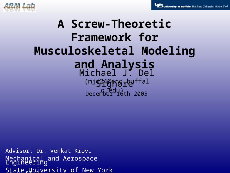
A Screw-Theoretic Framework for Musculoskeletal Modeling and
Analysis
Michael J. Del Signore ([email protected])
Advisor: Dr. Venkat KroviMechanical and Aerospace Engineering State University of New York at Buffalo
December 16th 2005

Michael J. Del SignoreDecember 16th 2005Slide 2 of 57
Automation, Robotics, and Mechatronics LAB – SUNY Buffalo
Agenda
• Introduction• Background• Case Scenario
• System Modeling• GUI Implementation
• Simulation Framework• Mechanical Prototype Design • Future Work• Conclusion
Michael J. Del SignoreDecember 16th 2005Slide 3 of 57
Automation, Robotics, and Mechatronics LAB – SUNY Buffalo
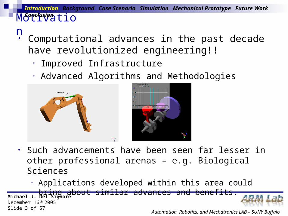
Motivation
• Such advancements have been seen far lesser in other professional arenas – e.g. Biological Sciences
• Applications developed within this area could bring about similar advances and benefits.
Introduction Background Case Scenario Simulation Mechanical Prototype Future Work Conclusion
• Computational advances in the past decade have revolutionized engineering!!
• Improved Infrastructure• Advanced Algorithms and Methodologies
Michael J. Del SignoreDecember 16th 2005Slide 4 of 57
Automation, Robotics, and Mechatronics LAB – SUNY Buffalo
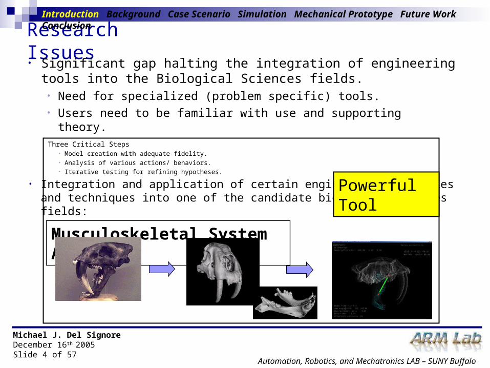
Research Issues • Significant gap halting the integration of engineering tools into
the Biological Sciences fields. • Need for specialized (problem specific) tools.• Users need to be familiar with use and supporting theory.
• Integration and application of certain engineering principles and techniques into one of the candidate biological sciences fields:
Musculoskeletal System Analysis
Powerful Tool
Three Critical Steps• Model creation with adequate fidelity.• Analysis of various actions/ behaviors.• Iterative testing for refining hypotheses.
Introduction Background Case Scenario Simulation Mechanical Prototype Future Work Conclusion

Michael J. Del SignoreDecember 16th 2005Slide 5 of 57
Automation, Robotics, and Mechatronics LAB – SUNY Buffalo
Challenges
• Unlike traditional engineering systems, musculoskeletal systems inherently possess considerable irregularities and redundancies.Irregularities Redundancies
• Complex Asymmetric Geometric Complex Asymmetric Geometric Shapes (i.e. muscle, bone).Shapes (i.e. muscle, bone).
• Each specimen is unique.Each specimen is unique.
• Dealing with (trying to simulate) Dealing with (trying to simulate) living tissue.living tissue.
• Multiple Muscles: More actuators Multiple Muscles: More actuators than degrees of freedom.than degrees of freedom.
• Infinite set of actuator (muscle) Infinite set of actuator (muscle) forces can produce the same end-forces can produce the same end-effector force.effector force.
• Musculoskeletal analysis tools need to take these characteristics into account.
Introduction Background Case Scenario Simulation Mechanical Prototype Future Work Conclusion

Michael J. Del SignoreDecember 16th 2005Slide 6 of 57
Automation, Robotics, and Mechatronics LAB – SUNY Buffalo
• Traditional Articulated Mechanical System Analysis Tools• Virtual Prototyping – Virtual product simulation & testing• Examples: VisualNastran, ADAMS, Pro-Mechanica …
• Physics, Dynamics, FEA, Contact, Friction – Implementation into real-time control frameworks
• The limitations of these tools can be seen when dealing with more complex phenomena and systems.
• Complex Geometries• Redundant Actuation• High Number of Contacts
Existing Tools
Musculoskeletal System Analysis
Introduction Background Case Scenario Simulation Mechanical Prototype Future Work Conclusion

Michael J. Del SignoreDecember 16th 2005Slide 7 of 57
Automation, Robotics, and Mechatronics LAB – SUNY Buffalo
• While being successful at handling complex musculoskeletal systems these programs require:
• In depth physiological knowledge. • Extensive application specific programming and coding.
Existing Tools• Musculoskeletal System Analysis Tools
• In resent years tools have been developed to specifically model and analyze musculoskeletal systems.
• Examples: SIMM, AnyBody, LifeMod …
High Degree of Modeling and
Simulation Detail
Rapid Real-Time Simulation and Analysis Relatively
Impossible
Introduction Background Case Scenario Simulation Mechanical Prototype Future Work Conclusion

Michael J. Del SignoreDecember 16th 2005Slide 8 of 57
Automation, Robotics, and Mechatronics LAB – SUNY Buffalo
Research Goal• The development of computational tools that can analyze a
redundant musculoskeletal system, incorporating:• An adequate degree of speed• Accurate redundancy resolution• Application in a real-time model based control framework
• Undertaken using screw-theoretic modeling methods:• Typically seen with the context of parallel manipulators.• Convenient basis for redundancy resolution and optimization.
• Critical aspects addressed within a specific case scenario:• Musculoskeletal Analysis of the Jaw Closure of a Saber-Tooth Cat
(Smilodon-Fatalis).
Introduction Background Case Scenario Simulation Mechanical Prototype Future Work Conclusion
Michael J. Del SignoreDecember 16th 2005Slide 9 of 57
Automation, Robotics, and Mechatronics LAB – SUNY Buffalo
Related Works• Musculoskeletal Modeling
• Multi-body Dynamics Approach [Forster, 2003]
• Detailed Muscle Modeling (Hill Model)[Wolkotte, 2003]
• Muscle Modeling and Software Development (Anybody) [Rasmussen, Damsgaard, Surma, Christensen, de Zee, and Vondrack, 2003] [Konakanchi, 2005]
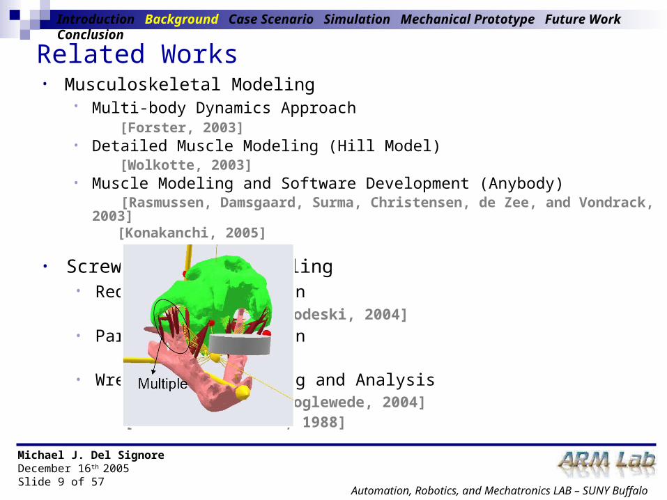
• Screw-Theoretic Modeling• Redundancy Resolution
[Firmani and Podhorodeski, 2004]• Parallel Manipulation
[Tsi, 1999]• Wrench Based Modeling and Analysis
[Ebert-Uphoff and Voglewede, 2004][Kumar and Waldron, 1988]
Introduction Background Case Scenario Simulation Mechanical Prototype Future Work Conclusion
Michael J. Del SignoreDecember 16th 2005Slide 10 of 57
Automation, Robotics, and Mechatronics LAB – SUNY Buffalo
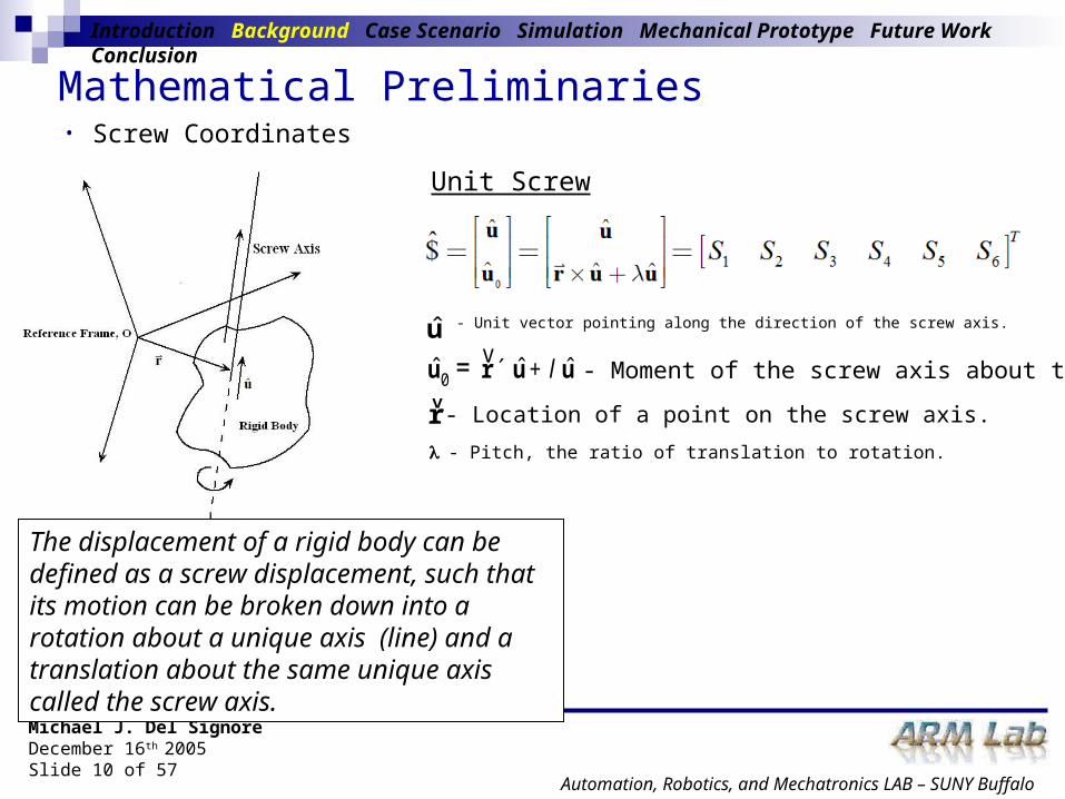
Mathematical Preliminaries• Screw Coordinates
The displacement of a rigid body can be defined as a screw displacement, such that its motion can be broken down into a rotation about a unique axis (line) and a translation about the same unique axis called the screw axis.
Unit Screw
u - Unit vector pointing along the direction of the screw axis.
0ˆ ˆ ˆu r u ul´ += v- Moment of the screw axis about the origin.
- Location of a point on the screw axis. rv
- Pitch, the ratio of translation to rotation.
Introduction Background Case Scenario Simulation Mechanical Prototype Future Work Conclusion
Michael J. Del SignoreDecember 16th 2005Slide 11 of 57
Automation, Robotics, and Mechatronics LAB – SUNY Buffalo
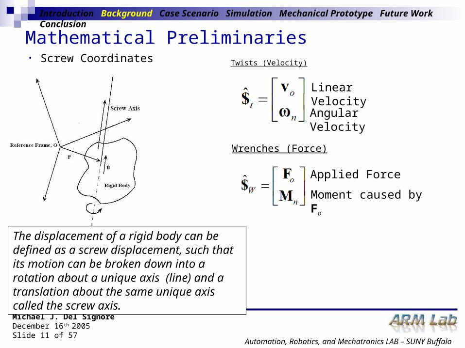
Mathematical Preliminaries• Screw Coordinates
The displacement of a rigid body can be defined as a screw displacement, such that its motion can be broken down into a rotation about a unique axis (line) and a translation about the same unique axis called the screw axis.
Twists (Velocity)
Wrenches (Force)
Linear Velocity
Angular Velocity
Applied Force
Moment caused by Fo
Introduction Background Case Scenario Simulation Mechanical Prototype Future Work Conclusion

Michael J. Del SignoreDecember 16th 2005Slide 12 of 57
Automation, Robotics, and Mechatronics LAB – SUNY Buffalo
Musculoskeletal Analysis of the Jaw Closure of the Smilodon
• Accurately model and simulate the skull/ mandible musculoskeletal structure of the Smilodon
Introduction Background Case Scenario Simulation Mechanical Prototype Future Work Conclusion

Michael J. Del SignoreDecember 16th 2005Slide 13 of 57
Automation, Robotics, and Mechatronics LAB – SUNY Buffalo
Preliminary Simulations• Undertaken using traditional articulated mechanical system
tools.
Introduction Background Case Scenario Simulation Mechanical Prototype Future Work Conclusion
• Virtual Simulation of Mechanical Saber-Tooth Cat• Discovery Channel Model
Discovery Channel Model Virtual Recreation

Michael J. Del SignoreDecember 16th 2005Slide 14 of 57
Automation, Robotics, and Mechatronics LAB – SUNY Buffalo
Simulation of Mechanical Smilodon• Implemented using a prescribed motion analysis within
VisualNastran
• Simulation was successful but more complexity was desired.
Introduction Background Case Scenario Simulation Mechanical Prototype Future Work Conclusion

Michael J. Del SignoreDecember 16th 2005Slide 15 of 57
Automation, Robotics, and Mechatronics LAB – SUNY Buffalo
Virtual Prototyping of Smilodon from Fossil Records
• Virtual representation created from actual fossil records
• VisualNastran simulation created to calculate muscle forces necessary to produce a desired bite force.
Introduction Background Case Scenario Simulation Mechanical Prototype Future Work Conclusion

Michael J. Del SignoreDecember 16th 2005Slide 16 of 57
Automation, Robotics, and Mechatronics LAB – SUNY Buffalo
Smilodon Virtual Prototype – VisualNastran
Introduction Background Case Scenario Simulation Mechanical Prototype Future Work Conclusion
• Constraints were placed on the system to represent:
• Muscles Linear Actuators
• Skull/ Mandible Interaction Revolute Joint
• External forces (or alternately a prescribed motion) was applied to the skull as user-specified input to the system.
• The simulation was met with limitations:• Due to the software's inability to handle redundancy in terms of
resolving the multiple muscle forces in an inverse dynamics setting.
• These shortcomings provided the motivation for the development of our own low-order computationally tractable model based on screw-theoretic methods.
Michael J. Del SignoreDecember 16th 2005Slide 17 of 57
Automation, Robotics, and Mechatronics LAB – SUNY Buffalo
Our Model
Introduction Background Case Scenario Simulation Mechanical Prototype Future Work Conclusion
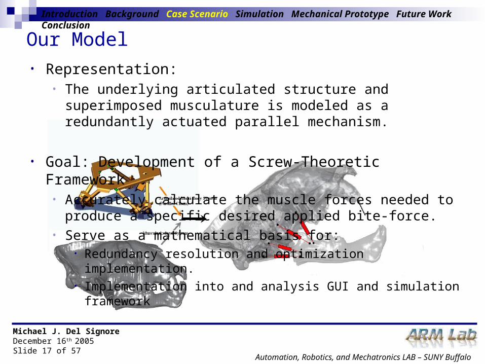
• Representation:• The underlying articulated structure and superimposed
musculature is modeled as a redundantly actuated parallel mechanism.
• Goal: Development of a Screw-Theoretic Framework• Accurately calculate the muscle forces needed to produce a
specific desired applied bite-force.• Serve as a mathematical basis for:
• Redundancy resolution and optimization implementation.• Implementation into and analysis GUI and simulation framework

Michael J. Del SignoreDecember 16th 2005Slide 18 of 57
Automation, Robotics, and Mechatronics LAB – SUNY Buffalo
Model Set Up• Assumptions
• Planar• Skull and mandible are rigid bodies.• The skull is attached to the mandible via a revolute joint. • Muscle act along the line of action joining the origin and
insertion points.
Introduction Background Case Scenario Simulation Mechanical Prototype Future Work Conclusion

Michael J. Del SignoreDecember 16th 2005Slide 19 of 57
Automation, Robotics, and Mechatronics LAB – SUNY Buffalo
Model Set UpIntroduction Background Case Scenario Simulation Mechanical Prototype Future Work Conclusion
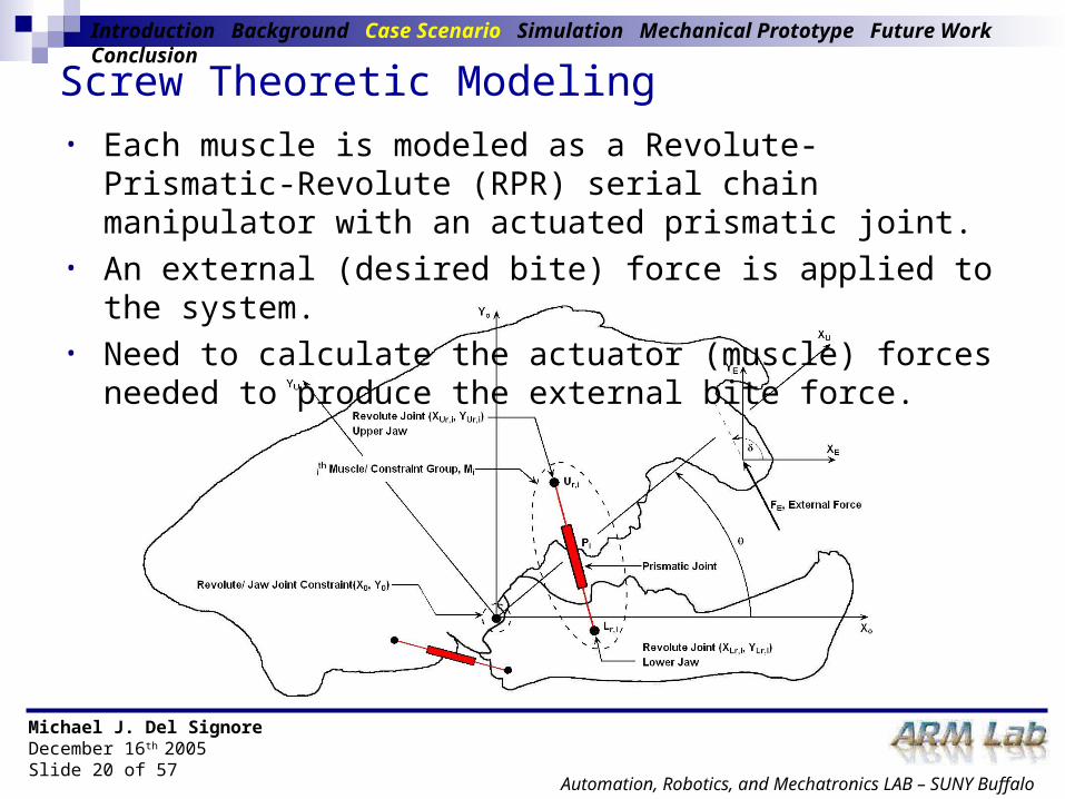
• Coordinate Frames• (Xo, Yo) Inertial Frame:
- Fixed in Space- Main Calculation Frame
• (XU, YU) Upper Jaw Frame:- Attached to Skull (Upper Jaw) - Related to Inertial Frame through
jaw gape angle • (XE, YE) End Effector Frame:
- Created with the application point of the external/ desired or bite force.
Michael J. Del SignoreDecember 16th 2005Slide 20 of 57
Automation, Robotics, and Mechatronics LAB – SUNY Buffalo
Introduction Background Case Scenario Simulation Mechanical Prototype Future Work Conclusion
• Each muscle is modeled as a Revolute-Prismatic-Revolute (RPR) serial chain manipulator with an actuated prismatic joint.
• An external (desired bite) force is applied to the system.• Need to calculate the actuator (muscle) forces needed to produce the
external bite force.
Screw Theoretic Modeling

Michael J. Del SignoreDecember 16th 2005Slide 21 of 57
Automation, Robotics, and Mechatronics LAB – SUNY Buffalo
• Calculate end-effector twist generated by every serial chain present in the system.
Introduction Background Case Scenario Simulation Mechanical Prototype Future Work Conclusion
RPR Chains (Muscles)
Revolute Jaw Joint Serial Chain
Jacobian matrix whose column vectors represent the unit screws associated with each joint in the ith RPR serial chain.
Unit screw created by the jaw joint.
Screw Theoretic Modeling

Michael J. Del SignoreDecember 16th 2005Slide 22 of 57
Automation, Robotics, and Mechatronics LAB – SUNY Buffalo
Introduction Background Case Scenario Simulation Mechanical Prototype Future Work Conclusion
• Unit screws
• Revolute Joints• Unit Screw with a pitch of zero ( = 0)
Upper Revolute Joint Lower Revolute Joint Jaw Revolute Joint
Screw Theoretic Modeling
• Prismatic Joints• Unit Screw with a pitch of infinity ( =∞)
Prismatic Joint

Michael J. Del SignoreDecember 16th 2005Slide 23 of 57
Automation, Robotics, and Mechatronics LAB – SUNY Buffalo
Introduction Background Case Scenario Simulation Mechanical Prototype Future Work Conclusion
• Unit screws
Screw Theoretic Modeling
Unit Direction Vectors
Distance Vectors

Michael J. Del SignoreDecember 16th 2005Slide 24 of 57
Automation, Robotics, and Mechatronics LAB – SUNY Buffalo
Introduction Background Case Scenario Simulation Mechanical Prototype Future Work Conclusion
• Combine and generate the Jacobian matrices corresponding to every serial chain in the system – and simplify to 2-dimensions.
RPR Serial Chains (Muscles) Jaw Joint
Screw Theoretic Modeling

Michael J. Del SignoreDecember 16th 2005Slide 25 of 57
Automation, Robotics, and Mechatronics LAB – SUNY Buffalo
Screw Theoretic ModelingIntroduction Background Case Scenario Simulation Mechanical Prototype Future Work Conclusion
• Reciprocal Wrench Formulation• Calculate the Selectively-Non-Reciprocal-Screws (SNRS) associated with the active joints (prismatic) in every serial chain. • SNRS – a screw which is reciprocal to all screws except the given screw.
Prismatic Joint Formulation Prismatic Joint Formulation
• WP,i is the SNRS to the unit screw corresponding to the Pi joint that satisfies:
iJ%- Modified Jacobian, in-active
joints only..
Jaw Joint Formulation Jaw Joint Formulation
Michael J. Del SignoreDecember 16th 2005Slide 26 of 57
Automation, Robotics, and Mechatronics LAB – SUNY Buffalo
Screw Theoretic ModelingIntroduction Background Case Scenario Simulation Mechanical Prototype Future Work Conclusion
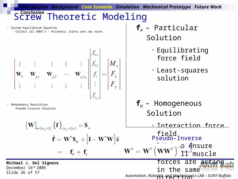
• System Equilibrium Equation • Collect all SNRS’s – Prismatic Joints and Jaw Joint.
fP – Particular Solution
• Equilibrating force field
• Least-squares solution
fH – Homogeneous Solution
• Interaction force field
• Used to ensure that all muscle forces are acting in the same direction.
• Redundancy Resolution • Pseudo-Inverse Solution
Pseudo-Inverse of W

Michael J. Del SignoreDecember 16th 2005Slide 27 of 57
Automation, Robotics, and Mechatronics LAB – SUNY Buffalo
Muscle Optimization
• Muscles produce force in only one direction (contraction).• Implemented optimization routines minimize muscle forces
while constraining them to remain positive (unidirectional)
• Two optimization routines are developed and implemented.• Muscle Force Optimization• Muscle Activity Optimization
Introduction Background Case Scenario Simulation Mechanical Prototype Future Work Conclusion
Michael J. Del SignoreDecember 16th 2005Slide 28 of 57
Automation, Robotics, and Mechatronics LAB – SUNY Buffalo
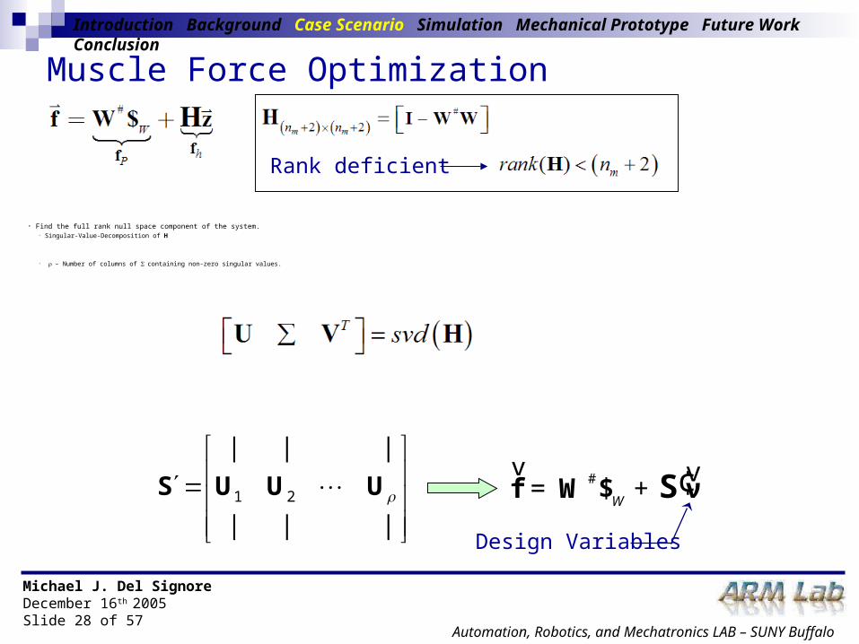
• Find the full rank null space component of the system.• Singular-Value-Decomposition of H
• – Number of columns of containing non-zero singular values.
Muscle Force Optimization
Introduction Background Case Scenario Simulation Mechanical Prototype Future Work Conclusion
Rank deficient
1 2
| | |
| | |
S U U U #
Wf W $ νS= + ¢v v
Design Variables

Michael J. Del SignoreDecember 16th 2005Slide 29 of 57
Automation, Robotics, and Mechatronics LAB – SUNY Buffalo
22 1 2 1
1
1 1m m m
oo Po
mm n Pm n n
Sf fν
Sf f
• Pseudo-Inverse Solution
• Separate Solution Components
Muscle Force Optimization
Jaw Joint Reaction Forces
Actuator (Muscle) Forces
• Force Optimization
Introduction Background Case Scenario Simulation Mechanical Prototype Future Work Conclusion

Michael J. Del SignoreDecember 16th 2005Slide 30 of 57
Automation, Robotics, and Mechatronics LAB – SUNY Buffalo
Muscle Activity Optimization• Normalized Muscle Activity
Introduction Background Case Scenario Simulation Mechanical Prototype Future Work Conclusion
Muscle Force
Maximum Muscle Force
• Muscle/ reaction forces in terms of activity.
• System Equilibrium Equation (Activity)
• Pseudo-Inverse Solution

Michael J. Del SignoreDecember 16th 2005Slide 31 of 57
Automation, Robotics, and Mechatronics LAB – SUNY Buffalo
Muscle Activity Optimization
Introduction Background Case Scenario Simulation Mechanical Prototype Future Work Conclusion
• Pseudo-Inverse (Activity) Solution
• Separate Solution Components
Jaw Joint Reaction Activities
Actuator (Muscle) Activities
• Activity Optimization
oo Po
mPmm
Sf fν
Sff
• Forces
Michael J. Del SignoreDecember 16th 2005Slide 32 of 57
Automation, Robotics, and Mechatronics LAB – SUNY Buffalo
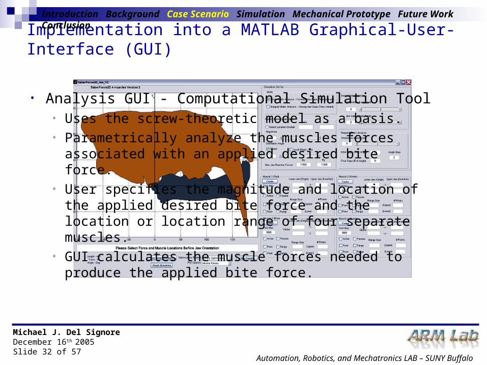
Implementation into a MATLAB Graphical-User-Interface (GUI)
Introduction Background Case Scenario Simulation Mechanical Prototype Future Work Conclusion
• Analysis GUI - Computational Simulation Tool• Uses the screw-theoretic model as a basis. • Parametrically analyze the muscles forces associated with an
applied desired bite force. • User specifies the magnitude and location of the applied
desired bite force and the location or location range of four separate muscles.
• GUI calculates the muscle forces needed to produce the applied bite force.

Michael J. Del SignoreDecember 16th 2005Slide 33 of 57
Automation, Robotics, and Mechatronics LAB – SUNY Buffalo
MATLAB Analysis GUI
Introduction Background Case Scenario Simulation Mechanical Prototype Future Work Conclusion
• Mode Selection• Applied Force Definition• Muscle Location Definition • Muscle Range Definition• Jaw Gape Definition• Optimization and Plot Options• Mode1 Results - Single Static• Mode2 Results - Stepped Static
Michael J. Del SignoreDecember 16th 2005Slide 34 of 57
Automation, Robotics, and Mechatronics LAB – SUNY Buffalo
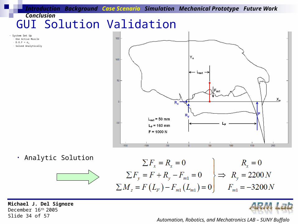
GUI Solution Validation
Introduction Background Case Scenario Simulation Mechanical Prototype Future Work Conclusion
• Analytic Solution
• System Set Up• One Active Muscle• D.O.F = nm
• Solved Analytically

Michael J. Del SignoreDecember 16th 2005Slide 35 of 57
Automation, Robotics, and Mechatronics LAB – SUNY Buffalo
GUI Solution Validation
Introduction Background Case Scenario Simulation Mechanical Prototype Future Work Conclusion
Michael J. Del SignoreDecember 16th 2005Slide 36 of 57
Automation, Robotics, and Mechatronics LAB – SUNY Buffalo
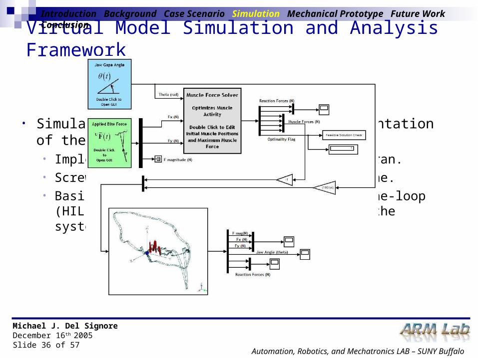
Virtual Model Simulation and Analysis Framework
• Simulation of the simplified (2D) representation of the Smilodon musculoskeletal system.
• Implemented within Simulink and VisualNastran.• Screw-Theoretic Model – main solution engine. • Basis for real-time control/ hardware-in-the-loop (HIL)
simulation of a mechanical model of the system.
Introduction Background Case Scenario Simulation Mechanical Prototype Future Work Conclusion

Michael J. Del SignoreDecember 16th 2005Slide 37 of 57
Automation, Robotics, and Mechatronics LAB – SUNY Buffalo
Data / Information Flow
Introduction Background Case Scenario Simulation Mechanical Prototype Future Work Conclusion
Michael J. Del SignoreDecember 16th 2005Slide 38 of 57
Automation, Robotics, and Mechatronics LAB – SUNY Buffalo
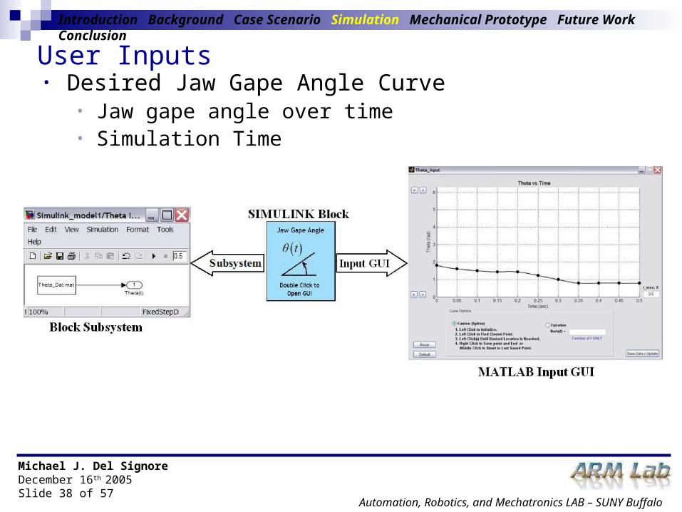
User Inputs• Desired Jaw Gape Angle Curve
• Jaw gape angle over time• Simulation Time
Introduction Background Case Scenario Simulation Mechanical Prototype Future Work Conclusion

Michael J. Del SignoreDecember 16th 2005Slide 39 of 57
Automation, Robotics, and Mechatronics LAB – SUNY Buffalo
User Inputs• Desired Bite Force Curve
• Bite Force with respect to upper jaw over time
Introduction Background Case Scenario Simulation Mechanical Prototype Future Work Conclusion
Michael J. Del SignoreDecember 16th 2005Slide 40 of 57
Automation, Robotics, and Mechatronics LAB – SUNY Buffalo
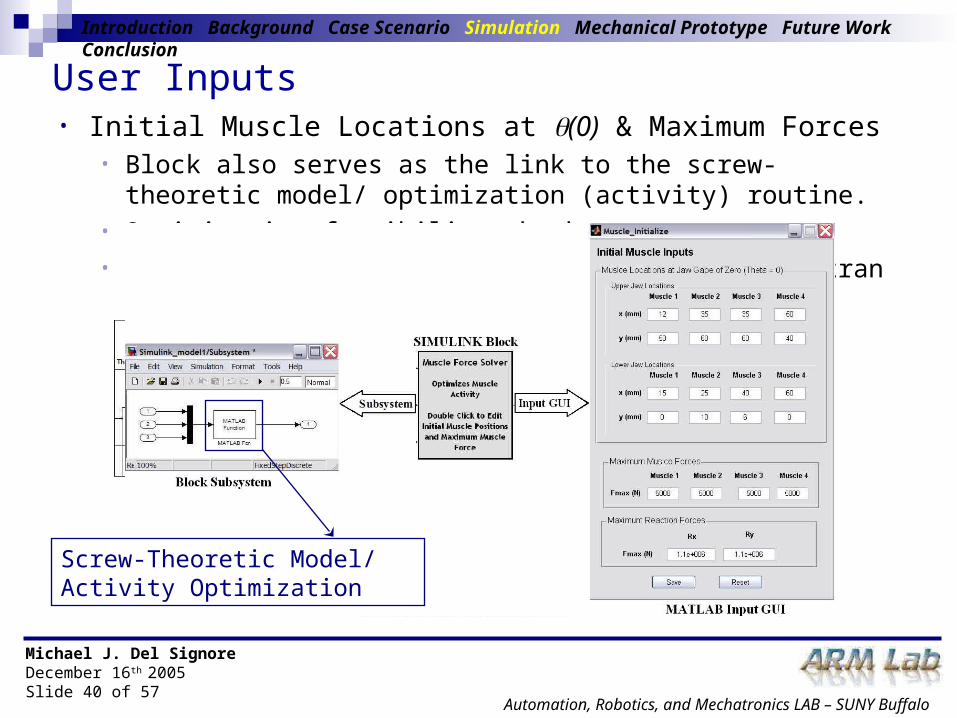
User Inputs• Initial Muscle Locations at (0) & Maximum Forces
• Block also serves as the link to the screw-theoretic model/ optimization (activity) routine.
• Optimization feasibility check• Provides muscle (actuator) forces to VisualNastran model.
Introduction Background Case Scenario Simulation Mechanical Prototype Future Work Conclusion
Screw-Theoretic Model/ Activity Optimization

Michael J. Del SignoreDecember 16th 2005Slide 41 of 57
Automation, Robotics, and Mechatronics LAB – SUNY Buffalo
VisualNastran Simulink Block• Dynamic in-the-loop link between Simulink and
VisualNastran.
Introduction Background Case Scenario Simulation Mechanical Prototype Future Work Conclusion
Michael J. Del SignoreDecember 16th 2005Slide 42 of 57
Automation, Robotics, and Mechatronics LAB – SUNY Buffalo
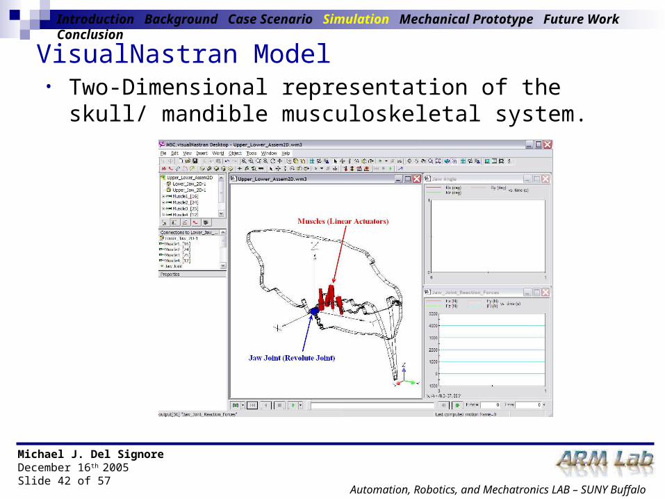
VisualNastran Model• Two-Dimensional representation of the skull/ mandible
musculoskeletal system.
Introduction Background Case Scenario Simulation Mechanical Prototype Future Work Conclusion
Michael J. Del SignoreDecember 16th 2005Slide 43 of 57
Automation, Robotics, and Mechatronics LAB – SUNY Buffalo
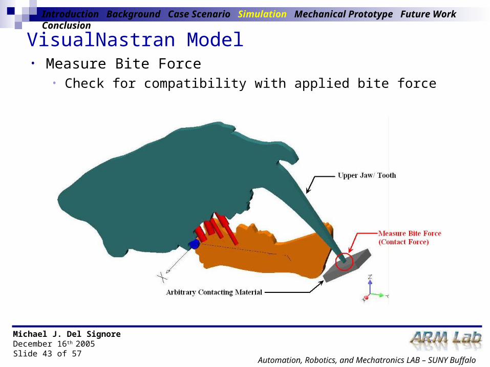
VisualNastran Model• Measure Bite Force
• Check for compatibility with applied bite force
Introduction Background Case Scenario Simulation Mechanical Prototype Future Work Conclusion

Michael J. Del SignoreDecember 16th 2005Slide 44 of 57
Automation, Robotics, and Mechatronics LAB – SUNY Buffalo
Framework Simulations• Four simulations
• Identical Simulation Parameters – tmax, t, … etc
• Varying/ Constant Jaw Gape• Varying/ Constant Bite Force
Introduction Background Case Scenario Simulation Mechanical Prototype Future Work Conclusion
Michael J. Del SignoreDecember 16th 2005Slide 45 of 57
Automation, Robotics, and Mechatronics LAB – SUNY Buffalo
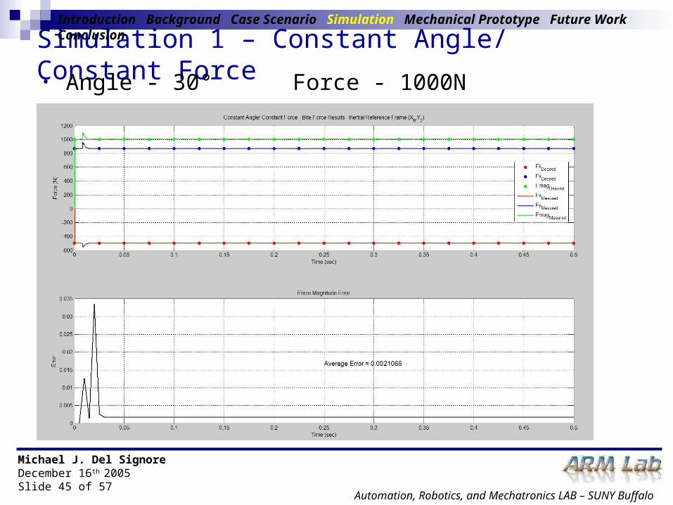
Simulation 1 – Constant Angle/ Constant Force
Introduction Background Case Scenario Simulation Mechanical Prototype Future Work Conclusion
• Angle - 30° Force - 1000N

Michael J. Del SignoreDecember 16th 2005Slide 46 of 57
Automation, Robotics, and Mechatronics LAB – SUNY Buffalo
Simulation 2 – Constant Angle/ Varying Force
Introduction Background Case Scenario Simulation Mechanical Prototype Future Work Conclusion
• Angle - 30° Force - 1000N to 500N

Michael J. Del SignoreDecember 16th 2005Slide 47 of 57
Automation, Robotics, and Mechatronics LAB – SUNY Buffalo
Simulation 3 – Varying Angle/ Constant Force
Introduction Background Case Scenario Simulation Mechanical Prototype Future Work Conclusion
• Angle - 30° to 0° Force - 1000N

Michael J. Del SignoreDecember 16th 2005Slide 48 of 57
Automation, Robotics, and Mechatronics LAB – SUNY Buffalo
Simulation 4 – Varying Angle/ Varying Force
Introduction Background Case Scenario Simulation Mechanical Prototype Future Work Conclusion
• Angle - 30° to 0° Force - 1000N to 500N

Michael J. Del SignoreDecember 16th 2005Slide 49 of 57
Automation, Robotics, and Mechatronics LAB – SUNY Buffalo
Simulation Summary
Introduction Background Case Scenario Simulation Mechanical Prototype Future Work Conclusion
• Error peaks occur at same time. • Simulation Settling. • Rotation of arbitrary material.
Michael J. Del SignoreDecember 16th 2005Slide 50 of 57
Automation, Robotics, and Mechatronics LAB – SUNY Buffalo
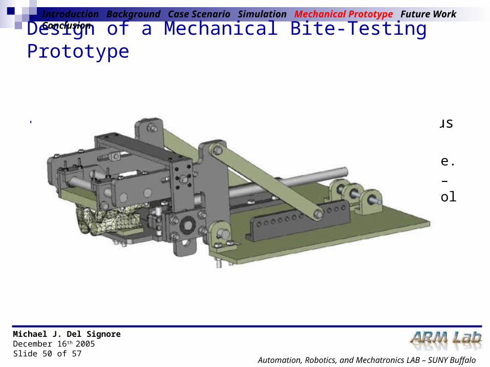
Design of a Mechanical Bite-Testing Prototype
• Designed to simulate biting actions of various large felines• Accepts various dentition castings – adjustable.• Initial design developed for manual operation – with eventual
implementation of computer control (HIL simulations)• Currently in preliminary manufacturing stages.
Introduction Background Case Scenario Simulation Mechanical Prototype Future Work Conclusion

Michael J. Del SignoreDecember 16th 2005Slide 51 of 57
Automation, Robotics, and Mechatronics LAB – SUNY Buffalo
Dentition Castings• CAD models developed from fossil records.
Introduction Background Case Scenario Simulation Mechanical Prototype Future Work Conclusion

Michael J. Del SignoreDecember 16th 2005Slide 52 of 57
Automation, Robotics, and Mechatronics LAB – SUNY Buffalo
Mechanism Adjustability
Introduction Background Case Scenario Simulation Mechanical Prototype Future Work Conclusion
• Ensure proper dentition location.• Locks in place during use.
Rotation Point LocationSkull/Mandible Location

Michael J. Del SignoreDecember 16th 2005Slide 53 of 57
Automation, Robotics, and Mechatronics LAB – SUNY Buffalo
Mechanical Prototype – Force/ Torque Analysis GUI
Introduction Background Case Scenario Simulation Mechanical Prototype Future Work Conclusion

Michael J. Del SignoreDecember 16th 2005Slide 54 of 57
Automation, Robotics, and Mechatronics LAB – SUNY Buffalo
Future Work• Completion of Mechanical Prototype
• Implementation of cable-actuation strategy – simulating muscles.• Implementation into real-time HIL control analysis framework.
• Extension Screw-Theoretic Model to Three-Dimensions• Higher degree of complexity and realism.• Additional analysis GUI.• Provide modeling and solution basis for HIL simulations.
• Implementation of Muscle Physiological Properties• Max muscle force currently only property considered.• Insight into what types of muscles are needed to produce desired
bite force.• Preliminary inclusion of physiological muscle properties explored
using Virtual Muscle (Simulink muscle model).
Introduction Background Case Scenario Simulation Mechanical Prototype Future Work Conclusion
Michael J. Del SignoreDecember 16th 2005Slide 55 of 57
Automation, Robotics, and Mechatronics LAB – SUNY Buffalo
Conclusions• Application of existing tools to musculoskeletal system analysis was
explored.• Traditional engineering tools found inadequate at handling inherent
system redundancies.• Specific musculoskeletal modeling tools require a high amount
modeling detail and application specific programming – rapid real-time simulation and analysis relatively impossible.
• Developed a screw-theoretic framework for modeling and analyzing the skull/mandible musculoskeletal system of a saber-tooth cat.
• Modeled as a redundantly actuated parallel manipulator.• Framework resolves muscle forces needed to produce a desired bite
force.• Redundancy resolution scheme implemented a typical pseudo-inverse
solution methodology.• Muscle force and activity optimizations were explored and
implemented.
Introduction Background Case Scenario Simulation Mechanical Prototype Future Work Conclusion

Michael J. Del SignoreDecember 16th 2005Slide 56 of 57
Automation, Robotics, and Mechatronics LAB – SUNY Buffalo
Conclusions• Screw-Theoretic Framework provided the basis for the development of a
MATLAB analysis GUI • Parametrically analyses the muscle forces or activities (four muscle)
needed to produce a desired bite force.• Virtual simulation framework developed.
• Simulated a virtual representation of the saber-tooth cat.• Implemented within Simulink and VisualNastran.• Measured bite force compared to the applied bite-force. • Overall the simulation was successful.
• Introduced a mechanical bite-testing prototype.• Perform bite testing simulations on various large felines.• Basis for implementation into real-time HIL analyses.
• Overall the developed screw-theoretic modeling and analysis framework shows significant promise at speeding up the musculoskeletal system analysis processes.
Introduction Background Case Scenario Simulation Mechanical Prototype Future Work Conclusion

Michael J. Del SignoreDecember 16th 2005Slide 57 of 57
Automation, Robotics, and Mechatronics LAB – SUNY Buffalo
Thank You
Questions?