Embed Size (px)
Citation preview
A Scalable Micro Wireless Interconnect Structure for CMPs
Suk-Bok Lee†, Sai-Wang Tam‡, Ioannis Pefkianakis†, Songwu Lu†, M. Frank Chang‡,Chuanxiong Guo∗, Glenn Reinman†, Chunyi Peng∗, Mishali Naik†, Lixia Zhang†, Jason Cong†
†UCLA Computer Science ‡UCLA Electrical Engineering ∗Microsoft Research Asia{sblee,pefkian,slu,reinman,mishali,lixia,cong}@cs.ucla.edu,
{roccotam,mfchang}@ee.ucla.edu, {chguo,chunyip}@microsoft.com
ABSTRACTThis paper describes an unconventional way to apply wireless net-working in emerging technologies. It makes the case for usinga two-tier hybrid wireless/wired architecture to interconnect hun-dreds to thousands of cores in chip multiprocessors (CMPs), wherecurrent interconnect technologies face severe scaling limitations inexcessive latency, long wiring, and complex layout. We proposea recursive wireless interconnect structure called the WCube thatfeatures a single transmit antenna and multiple receive antennasat each micro wireless router and offers scalable performance interms of latency and connectivity. We show the feasibility to buildminiature on-chip antennas, and simple transmitters and receiversthat operate at 100 − 500 GHz sub-terahertz frequency bands. Wealso devise new two-tier wormhole based routing algorithms thatare deadlock free and ensure a minimum-latency route on a 1000-core on-chip interconnect network. Our simulations show that ourprotocol suite can reduce the observed latency by 20% to 45%,and consumes power that is comparable to or less than current 2-Dwired mesh designs.
Categories and Subject DescriptorsC.1.2 [Multiple Data Stream Architectures (Multiprocessors)]:Interconnection architectures; C.2.1 [Network Architecture andDesign]: Wireless communication
General TermsAlgorithms, Design
KeywordsChip multiprocessors, On-chip wireless interconnection network
1. INTRODUCTIONIn this paper, we explore a new area for the application of wire-
less networking technology. We devise a novel wireless networkstructure and associated protocols to interconnect hundreds to thou-sands of cores in a multi-core chip multiprocessor (CMP). Current
Permission to make digital or hard copies of all or part of this work forpersonal or classroom use is granted without fee provided that copies arenot made or distributed for profit or commercial advantage and that copiesbear this notice and the full citation on the first page. To copy otherwise, torepublish, to post on servers or to redistribute to lists, requires prior specificpermission and/or a fee.MobiCom’09, September 20–25, 2009, Beijing, China.Copyright 2009 ACM 978-1-60558-702-8/09/09 ...$10.00.
generation interconnect solutions [23, 24, 32] face severe scalinglimitations as the core population grows into the upper hundredsor even lower thousands, including excessive latency due to largehop counts, long wires, many intermediate repeaters, and complexwiring layout. We argue that wireless networking has tremendouspromise as a scalable interconnect architecture for future genera-tion CMPs.Our research is motivated by several factors. CMP’s have been
widely acclaimed as the architecture of choice for future high-performanceprocessors [1, 28]. Today’s CMPs support tens to low hundreds ofcores, including Intel’s 80-core Terascale chip [32] and NVIDIA’s128-core Quadro GPU [26]. Both industrial and academic roadmapsproject that we will see commodity CMP core counts in the upperhundreds or even thousands in the near future [4, 5, 25]. For exam-ple, Intel expects to have CMPs with high hundreds to low thou-sands of cores within ten years [5, 22]. Such a large amount of re-sources argues for new parallel programming paradigms to harnessthis processing power [19], and new OS efforts to manage theseresources [10]. However, there still remains the question of howto scale the on-chip interconnect to provide low-latency and high-bandwidth communication between hundreds or even thousands ofcores.In this work, we set three specific goals in our design of a next
generation, scalable on-chip interconnect structure for CMPs. First,the network architecture must scale to a large number of cores (e.g.,accommodating potentially thousands of cores). This implies thatit needs to ensure small hop counts and rich connectivity while re-ducing the use of long wires. Second, the structure and protocolsmust provide low network latency to minimize the time taken byinter-core data communications. Third, the operation must be sim-ple enough to be implementable at the microarchitecture level.In this paper, we make a case for a micro wireless intercon-
nect architecture for CMPs with hundreds to thousands of cores.This wireless network-on-chip (NoC) architecture uses a two-tieredstructure – a wireless backbone and wired edges, in contrast to to-day’s wireless Internet architecture of a wired backbone and wire-less edges. The wired two-dimensional mesh topology serves as thenetwork edge and offers a local route for neighborhood inter-coremessage exchanges. The wireless structure provides wireless ex-press pathways for long-haul, inter-core communication to ensureimproved connectivity and reduced latency. Within this wirelessinterconnect, we also show the feasibility for novel, micro wirelessrouters. Each wireless router has a single transmitter and multi-ple receivers, both in very simple forms. These routers commu-nicate wirelessly at tens of Gbps speed over the 100 − 500 GHz,sub-Terahertz band via miniature on-chip antennas. External inter-ference is negligible for CMPs at this high frequency band due tomasking and the relatively few operational devices that are present.
Another benefit is that wireless signals attenuate too rapidly in thefree space to create any interference for other devices. The transmitpower we use is also too small to conflict with FCC regulations.To realize the wireless on-chip interconnect architecture, we pro-
pose a new wireless interconnect structure called the WCube anddevise routing and MAC protocols to leverage this architecture.WCube uses a recursively-defined structure to interconnect microwireless routers (MWR) wirelessly, each of which is responsiblefor a local cluster of cores on the baseline mesh. It is a multi-level,two-dimensional (vertical and horizontal) structure, in that eachMWR has wireless connections to different levels ofWCubes alongboth dimensions via frequency division multiple access (FDMA)techniques. WCube scales exponentially with the MWR’s logicalconnection degree, and its diameter is proportional to the WCubelevel. In practice, a WCube with even a small number of lev-els (e.g. 2), together with the baseline 2-D mesh, can support1000s of cores with low network latency (e.g. at most 4 wire-less hops for inter-core communication). With WCube in place,we also devise a new two-tier, wormhole-based routing algorithmthat enables flit (i.e. a fragment in a packet) pipelining and ensuresminimum-latency routes. The algorithm avoids packet-forwardingdeadlocks, which occur due to cyclic dependences among multi-ple packet flows (note: these are different from routing loops). Wealso design a simple MAC that exploits multi-receiver capabilityand takes an FDMA based, cross-layer design approach. Overall,the WCube protocol operations such as routing decision logic andMAC unit are simple enough to be implemented at the microarchi-tecture level. Our simulation-based evaluations demonstrate thatthe latency can be reduced by 20% to 45%with comparable or evenlower power consumption compared with the current 2-D mesh de-sign.The rest of the paper is organized as follows. Section 2 intro-
duces the existing interconnect solutions for CMPs, and Section3 describes scaling limitations of current solutions to 1000s-coreCMPs. Section 4 makes a case for on-chip wireless interconnectand demonstrates its feasibility. Section 5 presents WCube, a newwireless interconnect structure for 1000s-of-cores CMPs, and Sec-tion 6 describes routing and MAC protocols over WCube. Section7 evaluates its performance. Section 8 discusses related issues, andSection 9 concludes the paper.
2. BACKGROUND
2.1 Chip Multi-Processors (CMPs)In recent years, the performance increases possible with conven-
tional superscalar single-core processors have encountered funda-mental limits [1, 5], leading to an industry-wide turn towards chipmultiprocessor (CMP) systems.CMPs are becoming ubiquitous in all computing domains rang-
ing from general purpose servers (e.g. DEC Piranha [6]) to thedomain specific processors (e.g. NVIDIA Quadro FX 5600 [26])– from 3G cellular base stations (e.g. picoChip PC205 [15]) tothe latest game consoles (e.g. IBM/Microsoft Xenon Xbox360 [2]and Sony/Toshiba/IBM Cell PlayStation3 [23]). These CMPs to-day have dozens of tiled cores on a single chip. As the technol-ogy progresses, the core count is expected to grow to hundredsor even thousands in the near future [4, 5, 25]. Conventional wis-dom is to double the number of cores on a chip with each sili-con generation [4]. For example, the latest release (Fall 2008) ofNVIDIA Tesla C1060 GPU has as many as 240 cores integratedin a chip [27]. The fact that such a high number of cores will betightly integrated onto the same die presents a fundamental chal-lenge for on-chip communication among cores, which is different
router
core
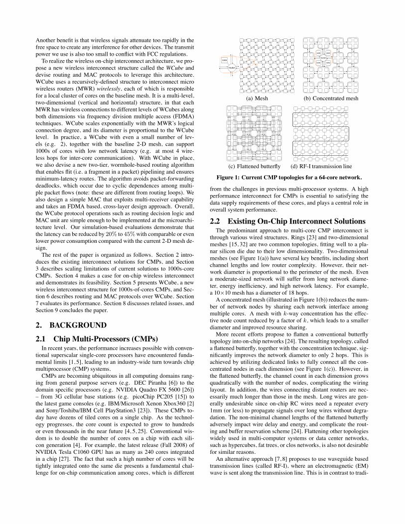
(a) Mesh
core core
core core
router
(b) Concentrated mesh
(c) Flattened butterfly (d) RF-I transmission line
Figure 1: Current CMP topologies for a 64-core network.
from the challenges in previous multi-processor systems. A highperformance interconnect for CMPs is essential to satisfying thedata supply requirements of these cores, and plays a central role inoverall system performance.
2.2 Existing On-Chip Interconnect SolutionsThe predominant approach to multi-core CMP interconnect is
through various wired structures. Rings [23] and two-dimensionalmeshes [15, 32] are two common topologies, fitting well to a pla-nar silicon die due to their low dimensionality. Two-dimensionalmeshes (see Figure 1(a)) have several key benefits, including shortchannel lengths and low router complexity. However, their net-work diameter is proportional to the perimeter of the mesh. Evena moderate-sized network will suffer from long network diame-ter, energy inefficiency, and high network latency. For example,a 10×10 mesh has a diameter of 18 hops.A concentrated mesh (illustrated in Figure 1(b)) reduces the num-
ber of network nodes by sharing each network interface amongmultiple cores. A mesh with k-way concentration has the effec-tive node count reduced by a factor of k, which leads to a smallerdiameter and improved resource sharing.More recent efforts propose to flatten a conventional butterfly
topology into on-chip networks [24]. The resulting topology, calleda flattened butterfly, together with the concentration technique, sig-nificantly improves the network diameter to only 2 hops. This isachieved by utilizing dedicated links to fully connect all the con-centrated nodes in each dimension (see Figure 1(c)). However, inthe flattened butterfly, the channel count in each dimension growsquadratically with the number of nodes, complicating the wiringlayout. In addition, the wires connecting distant routers are nec-essarily much longer than those in the mesh. Long wires are gen-erally undesirable since on-chip RC wires need a repeater every1mm (or less) to propagate signals over long wires without degra-dation. The non-minimal channel lengths of the flattened butterflyadversely impact wire delay and energy, and complicate the rout-ing and buffer reservation scheme [24]. Flattening other topologieswidely used in multi-computer systems or data center networks,such as hypercubes, fat trees, or clos networks, is also not desirablefor similar reasons.An alternative approach [7, 8] proposes to use waveguide based
transmission lines (called RF-I), where an electromagnetic (EM)wave is sent along the transmission line. This is in contrast to tradi-
tional voltage signaling over a conventional resistance-capacitance(RC) wire, whose entire length has to be charged and discharged tosignify either a ‘1’ or ‘0’ in order to send information. This processof charging and discharging conventional RC lines can consumemore time and energy than transmission lines for longer wires. Fig-ure 1(d) shows the RF-I transmission line for a 64-core CMP. Trans-mission line-based interconnect offers several appealing propertiesover the traditional RC-wired interconnect. It can effectively re-duce network diameter and improve power savings for mid-sized(in the range of tens to lower hundreds of cores) multi-core inter-connect. Simulation evaluation also shows that RF-I can providean average 22% reduction in packet latency on a 64-core CMP [7],compared with the conventional 2D mesh.
3. SCALING LIMITATIONS OF CURRENTSOLUTIONS TO 1000S-CORE CMPS
The current interconnect solutions all face severe scaling chal-lenges when applied to CMPs with 100s to 1000s of cores. Wenow use a 1000-core example case to elaborate the scaling limita-tions of each solution. In this context, minimizing hop count turnsout to be critical, as intermediate routers are the source of signif-icant delay: typically five cycles per router. Moreover, long wiresare undesirable since on-chip RC wires need a repeater every 1mmor less to retain signal quality over long wires. From both perspec-tives, existing solutions to 1000-core CMPs either suffer from la-tency problems (e.g., ring, mesh, concentrated mesh), or face struc-tural limitations to accommodate 1000-core CMPs (e.g., flattenedbutterfly, RF-I transmission line).The ring topology is cost effective, yet the least scalable technol-
ogy. Its hop count grows linearly with the number of interconnectedcores. Therefore, its diameter approaches 500 when the number ofcores reaches 1000. The 2D mesh does not scale well, either. Itsnetwork diameter scales with the square root of the mesh size. Itresults in about a 60-hop diameter in the 1000-core case. Con-centrated meshes are better, but their scaling property is still poor.Since physical limitations restrict the degree of concentration (as inFigure 1(b), typically k = 4), a larger network still has unaccept-able network latency. A 1024-core mesh with 4-way concentrationhas a diameter of 30 hops.On the other hand, low-diameter topologies, such as flattened
butterfly, have severe wiring problems caused by a large numberof dedicated point-to-point links and long wires connecting distantrouters. As a result, flattened butterfly is not implementable forthousands of cores because of long wires and the fact that therewill be too many channels from each node. Note that long wireslead to long latency due to repeater insertion. Moreover, embed-ding conventional high-dimension topologies onto 2-D substratesis similarly prohibitive.Finally, while the RF-I transmission line based interconnect holds
great promise for the lower hundreds of cores, it also faces severalchallenges in the 1000-core setting. The RF-I transmission line(TR line) needs to span the entire chip area, and requires excessivebranching points to connect to local cores. Moreover, the TR line isnot as effective as antennas at very high frequencies. The cross-talk(or inter-channel interference) between adjacent TR lines may alsopose problems for long TR lines.In summary, a desirable CMP solution for 1000s-core CMPs
should feature (i) low dimensional baseline infrastructure that iscompatible with the planar VLSI layout constraint for on-chip net-works, and (ii) some form of express channels to ensure small-hopand rich connectivity [20]. In addition, it is desirable to avoid highwiring complexity and long wires.
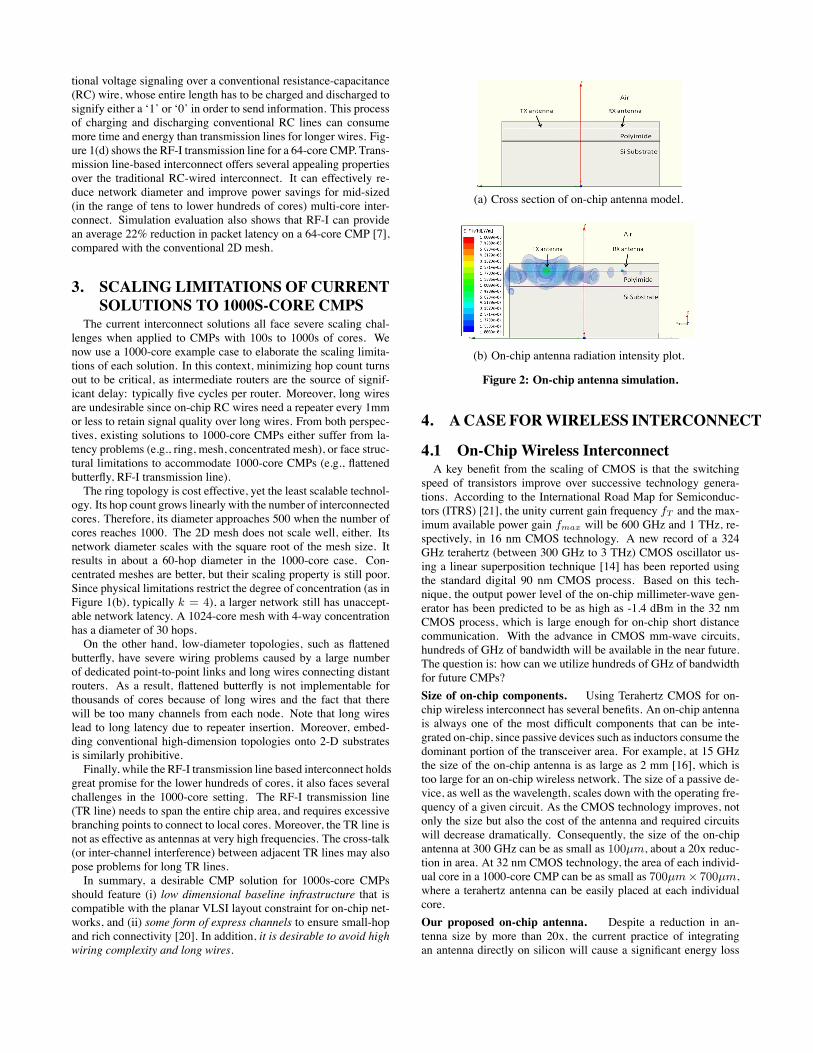
(a) Cross section of on-chip antenna model.
.
(b) On-chip antenna radiation intensity plot.
Figure 2: On-chip antenna simulation.
4. A CASE FORWIRELESS INTERCONNECT
4.1 On-Chip Wireless InterconnectA key benefit from the scaling of CMOS is that the switching
speed of transistors improve over successive technology genera-tions. According to the International Road Map for Semiconduc-tors (ITRS) [21], the unity current gain frequency fT and the max-imum available power gain fmax will be 600 GHz and 1 THz, re-spectively, in 16 nm CMOS technology. A new record of a 324GHz terahertz (between 300 GHz to 3 THz) CMOS oscillator us-ing a linear superposition technique [14] has been reported usingthe standard digital 90 nm CMOS process. Based on this tech-nique, the output power level of the on-chip millimeter-wave gen-erator has been predicted to be as high as -1.4 dBm in the 32 nmCMOS process, which is large enough for on-chip short distancecommunication. With the advance in CMOS mm-wave circuits,hundreds of GHz of bandwidth will be available in the near future.The question is: how can we utilize hundreds of GHz of bandwidthfor future CMPs?
Size of on-chip components. Using Terahertz CMOS for on-chip wireless interconnect has several benefits. An on-chip antennais always one of the most difficult components that can be inte-grated on-chip, since passive devices such as inductors consume thedominant portion of the transceiver area. For example, at 15 GHzthe size of the on-chip antenna is as large as 2 mm [16], which istoo large for an on-chip wireless network. The size of a passive de-vice, as well as the wavelength, scales down with the operating fre-quency of a given circuit. As the CMOS technology improves, notonly the size but also the cost of the antenna and required circuitswill decrease dramatically. Consequently, the size of the on-chipantenna at 300 GHz can be as small as 100μm, about a 20x reduc-tion in area. At 32 nm CMOS technology, the area of each individ-ual core in a 1000-core CMP can be as small as 700μm× 700μm,where a terahertz antenna can be easily placed at each individualcore.
Our proposed on-chip antenna. Despite a reduction in an-tenna size by more than 20x, the current practice of integratingan antenna directly on silicon will cause a significant energy loss
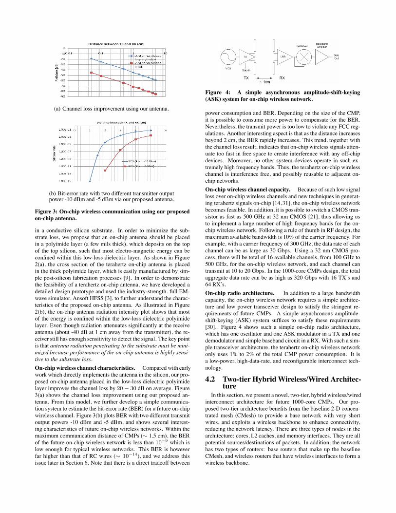
(a) Channel loss improvement using our antenna.
(b) Bit-error rate with two different transmitter outputpower -10 dBm and -5 dBm via our proposed antenna.
Figure 3: On-chip wireless communication using our proposedon-chip antenna.
in a conductive silicon substrate. In order to minimize the sub-strate loss, we propose that an on-chip antenna should be placedin a polyimide layer (a few mils thick), which deposits on the topof the top silicon, such that most electro-magnetic energy can beconfined within this low-loss dielectric layer. As shown in Figure2(a), the cross section of the terahertz on-chip antenna is placedin the thick polyimide layer, which is easily manufactured by sim-ple post-silicon fabrication processes [9]. In order to demonstratethe feasibility of a terahertz on-chip antenna, we have developed adetailed design prototype and used the industry-strength, full EM-wave simulator, Ansoft HFSS [3], to further understand the charac-teristics of the proposed on-chip antenna. As illustrated in Figure2(b), the on-chip antenna radiation intensity plot shows that mostof the energy is confined within the low-loss dielectric polyimidelayer. Even though radiation attenuates significantly at the receiveantenna (about -40 dB at 1 cm away from the transmitter), the re-ceiver still has enough sensitivity to detect the signal. The key pointis that antenna radiation penetrating to the substrate must be mini-mized because performance of the on-chip antenna is highly sensi-tive to the substrate loss.
On-chip wireless channel characteristics. Compared with earlywork which directly implements the antenna in the silicon, our pro-posed on-chip antenna placed in the low-loss dielectric polyimidelayer improves the channel loss by 20 − 30 dB on average. Figure3(a) shows the channel loss improvement using our proposed an-tenna. From this model, we further develop a simple communica-tion system to estimate the bit-error rate (BER) for a future on-chipwireless channel. Figure 3(b) plots BERwith two different transmitoutput powers -10 dBm and -5 dBm, and shows several interest-ing characteristics of future on-chip wireless networks. Within themaximum communication distance of CMPs (∼ 1.5 cm), the BERof the future on-chip wireless network is less than 10−9 which islow enough for typical wireless networks. This BER is howeverfar higher than that of RC wires (∼ 10−14), and we address thisissue later in Section 6. Note that there is a direct tradeoff between
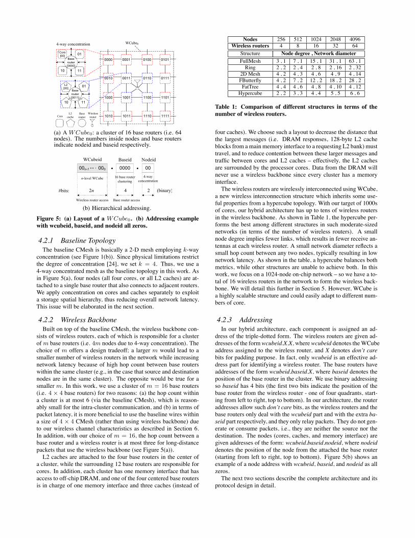
Figure 4: A simple asynchronous amplitude-shift-keying(ASK) system for on-chip wireless network.
power consumption and BER. Depending on the size of the CMP,it is possible to consume more power to compensate for the BER.Nevertheless, the transmit power is too low to violate any FCC reg-ulations. Another interesting aspect is that as the distance increasesbeyond 2 cm, the BER rapidly increases. This trend, together withthe channel loss result, indicates that on-chip wireless signals atten-uate too fast in free space to create interference with any off-chipdevices. Moreover, no other system devices operate in such ex-tremely high frequency bands. Thus, the terahertz on-chip wirelesschannel is interference free, and possibly reusable to adjacent on-chip networks.
On-chip wireless channel capacity. Because of such low signalloss over on-chip wireless channels and new techniques in generat-ing terahertz signals on-chip [14,31], the on-chip wireless networkbecomes feasible. In addition, it is possible to switch a CMOS tran-sistor as fast as 500 GHz at 32 nm CMOS [21], thus allowing usto implement a large number of high frequency bands for the on-chip wireless network. Following a rule of thumb in RF design, themaximum available bandwidth is 10% of the carrier frequency. Forexample, with a carrier frequency of 300 GHz, the data rate of eachchannel can be as large as 30 Gbps. Using a 32 nm CMOS pro-cess, there will be total of 16 available channels, from 100 GHz to500 GHz, for the on-chip wireless network, and each channel cantransmit at 10 to 20 Gbps. In the 1000-core CMPs design, the totalaggregate data rate can be as high as 320 Gbps with 16 TX’s and64 RX’s.
On-chip radio architecture. In addition to a large bandwidthcapacity, the on-chip wireless network requires a simple architec-ture and low power transceiver design to satisfy the stringent re-quirements of future CMPs. A simple asynchronous amplitude-shift-keying (ASK) system suffices to satisfy these requirements[30]. Figure 4 shows such a simple on-chip radio architecture,which has one oscillator and one ASK modulator in a TX and onedemodulator and simple baseband circuit in a RX. With such a sim-ple transceiver architecture, the terahertz on-chip wireless networkonly uses 1% to 2% of the total CMP power consumption. It isa low-power, high-data-rate, and reconfigurable interconnect tech-nology.
4.2 Two-tier HybridWireless/Wired Architec-ture
In this section, we present a novel, two-tier, hybrid wireless/wiredinterconnect architecture for future 1000-core CMPs. Our pro-posed two-tier architecture benefits from the baseline 2-D concen-trated mesh (CMesh) to provide a base network with very shortwires, and exploits a wireless backbone to enhance connectivity,reducing the network latency. There are three types of nodes in thearchitecture: cores, L2 caches, and memory interfaces. They are allpotential sources/destinations of packets. In addition, the networkhas two types of routers: base routers that make up the baselineCMesh, and wireless routers that have wireless interfaces to form awireless backbone.
0000
4-way concentration WCube0
CoreBase router
Wireless router
0001 0100 0101
0010 0011 0110 0111
1000 1001 1100 1101
1010 1011 1110 1111
Core [00] 01
10
Base router [0000]
L2 cache
11
Base router [0011]
11
L2 [00] 01
10
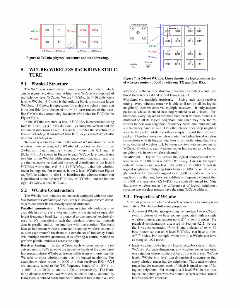
(a) A WCube0: a cluster of 16 base routers (i.e. 64nodes). The numbers inside nodes and base routersindicate nodeid and baseid respectively.
0000n-1 000 0000
WCubeid NodeidBaseid
#bits: 2n 4 2 (binary)
n-level WCube 4-way concentration
Wireless router access Base router access
16 base router clustering
(b) Hierarchical addressing.
Figure 5: (a) Layout of a WCube0. (b) Addressing examplewith wcubeid, baseid, and nodeid all zeros.
4.2.1 Baseline TopologyThe baseline CMesh is basically a 2-D mesh employing k-way
concentration (see Figure 1(b)). Since physical limitations restrictthe degree of concentration [24], we set k = 4. Thus, we use a4-way concentrated mesh as the baseline topology in this work. Asin Figure 5(a), four nodes (all four cores, or all L2 caches) are at-tached to a single base router that also connects to adjacent routers.We apply concentration on cores and caches separately to exploita storage spatial hierarchy, thus reducing overall network latency.This issue will be elaborated in the next section.
4.2.2 Wireless BackboneBuilt on top of the baseline CMesh, the wireless backbone con-
sists of wireless routers, each of which is responsible for a clusterofm base routers (i.e. 4m nodes due to 4-way concentration). Thechoice of m offers a design tradeoff; a larger m would lead to asmaller number of wireless routers in the network while increasingnetwork latency because of high hop count between base routerswithin the same cluster (e.g., in the case that source and destinationnodes are in the same cluster). The opposite would be true for asmaller m. In this work, we use a cluster of m = 16 base routers(i.e. 4 × 4 base routers) for two reasons: (a) the hop count withina cluster is at most 6 (via the baseline CMesh), which is reason-ably small for the intra-cluster communication, and (b) in terms ofpacket latency, it is more beneficial to use the baseline wires withina size of 4 × 4 CMesh (rather than using wireless backbone) dueto our wireless channel characteristics as described in Section 6.In addition, with our choice of m = 16, the hop count between abase router and a wireless router is at most three for long-distancepackets that use the wireless backbone (see Figure 5(a)).L2 caches are attached to the four base routers in the center of
a cluster, while the surrounding 12 base routers are responsible forcores. In addition, each cluster has one memory interface that hasaccess to off-chip DRAM, and one of the four centered base routersis in charge of one memory interface and three caches (instead of
Nodes 256 512 1024 2048 4096Wireless routers 4 8 16 32 64
Structure Node degree , Network diameter
FullMesh 3 , 1 7 , 1 15 , 1 31 , 1 63 , 1Ring 2 , 2 2 , 4 2 , 8 2 , 16 2 , 32
2D Mesh 4 , 2 4 , 3 4 , 6 4 , 9 4 , 14FButterfly 4 , 2 7 , 2 12 , 2 18 , 2 28 , 2FatTree 4 , 4 4 , 6 4 , 8 4 , 10 4 , 12Hypercube 2 , 2 3 , 3 4 , 4 5 , 5 6 , 6
Table 1: Comparison of different structures in terms of thenumber of wireless routers.
four caches). We choose such a layout to decrease the distance thatthe largest messages (i.e. DRAM responses, 128-byte L2 cacheblocks from amain memory interface to a requesting L2 bank) musttravel, and to reduce contention between these larger messages andtraffic between cores and L2 caches – effectively, the L2 cachesare surrounded by the processor cores. Data from the DRAM willnever use a wireless backbone since every cluster has a memoryinterface.The wireless routers are wirelessly interconnected usingWCube,
a new wireless interconnection structure which inherits some use-ful properties from a hypercube topology. With our target of 1000sof cores, our hybrid architecture has up to tens of wireless routersin the wireless backbone. As shown in Table 1, the hypercube per-forms the best among different structures in such moderate-sizednetworks (in terms of the number of wireless routers). A smallnode degree implies fewer links, which results in fewer receive an-tennas at each wireless router. A small network diameter reflects asmall hop count between any two nodes, typically resulting in lownetwork latency. As shown in the table, a hypercube balances bothmetrics, while other structures are unable to achieve both. In thiswork, we focus on a 1024-node on-chip network – so we have a to-tal of 16 wireless routers in the network to form the wireless back-bone. We will detail this further in Section 5. However, WCube isa highly scalable structure and could easily adapt to different num-bers of core.
4.2.3 AddressingIn our hybrid architecture, each component is assigned an ad-
dress of the triple-dotted form. The wireless routers are given ad-dresses of the formwcubeid.X.X, wherewcubeid denotes theWCubeaddress assigned to the wireless router, and X denotes don’t carebits for padding purpose. In fact, only wcubeid is an effective ad-dress part for identifying a wireless router. The base routers haveaddresses of the form wcubeid.baseid.X, where baseid denotes theposition of the base router in the cluster. We use binary addressingso baseid has 4 bits (the first two bits indicate the position of thebase router from the wireless router - one of four quadrants, start-ing from left to right, top to bottom). In our architecture, the routeraddresses allow such don’t care bits, as the wireless routers and thebase routers only deal with the wcubeid part and with the extra ba-seid part respectively, and they only relay packets. They do not gen-erate or consume packets, i.e., they are neither the source nor thedestination. The nodes (cores, caches, and memory interface) aregiven addresses of the form: wcubeid.baseid.nodeid, where nodeiddenotes the position of the node from the attached the base router(starting from left to right, top to bottom). Figure 5(b) shows anexample of a node address with wcubeid, baseid, and nodeid as allzeros.The next two sections describe the complete architecture and its
protocol design in detail.
00 01
10 11
WCube0
WCube1
A WCube1 = 4 WCube0s
00xx 01xx
10xx 11xx
WCube2
WCube1
A WCube2 = 4 WCube1s
Figure 6: WCube physical structure and its addressing.
5. WCUBE:WIRELESS BACKBONE STRUC-TURE
5.1 Physical StructureThe WCube is a multi-level, two-dimensional structure, which
can be recursively described. A high-level WCube is composed ofmultiple low-level WCubes. We useWCuben (n ≥ 0) to denote alevel-nWCube. WCube0 is the building block to construct largerWCubes. WCube0 is represented by a single wireless router thatis responsible for a cluster of m = 16 base routers of the base-line CMesh, thus comprising 4m nodes (64 nodes forWCube0 inFigure 5(a)).In the WCube structure, a level-i WCubei is constructed using
fourWCubei−1s (i.e. twoWCubei−1s along the vertical and thehorizontal dimensions each). Figure 6 illustrates the structure of alevel-2WCube2. It consists of fourWCube1s, each of which alsohas fourWCube0s in it.To identify a wireless router in the n-levelWCube structure, each
wireless router is assigned a WCube address (or wcubeid) of the2n-bit form < a2n−1a2n−2 · · · a1a0 >, where ai ∈ [0, 1] and i ∈[0, 2n − 1]. As shown in Figure 6, each WCube level contributestwo bits to the WCube addressing space such that a2i+1 and a2i
are the respective vertical and horizontal coordinates of the level-iWCubei within the level-(i + 1) WCube(i+1) that this wirelessrouter belongs to. For example, in the 2-level WCube (see Figure6), WCube address < 0011 > identifies the wireless router thatis positioned at the top left WCube1 in WCube2 and the bottomrightWCube0 in thatWCube1.
5.2 WCube ConstructionThe WCube uses wireless routers each equipped with one wire-
less transmitter and multiple receivers (i.e., multiple receive anten-nas) to construct its recursively defined structure.
Parallel transmission. Leveraging an extremely wide spectrumavailable in a chip, every wireless router ν is assigned a single, dif-ferent frequency band (i.e. orthogonal to one another) exclusivelyused for ν’s transmission such that wireless routers can transmitdata in parallel and do not interfere with one another. The basicidea to implement wireless connection among wireless routers isto tune each router’s receivers to a certain set of frequency bands(via multiple receive antennas), thus offering a natural method toperform parallel multicast across the chip.
Receiver tuning. In the WCube, each wireless router ν’s re-ceivers are statically tuned to the frequency bands of the other wire-less routers whose WCube addresses differ from ν in only one bit.We refer to those wireless routers as ν’s logical neighbors. Forexample, wireless router < 0000 >’s four receivers RX1∼RX4are statically tuned to the TX frequency bands of < 0001 >,< 0010 >, < 0100 >, and < 1000 >, respectively. The Ham-ming distance between two wireless routers ν and υ, denoted byHam(ν,υ), is defined as the number of different bits in their WCube
0000 0001
0010 0011
0100 0101
0110 0111
1000 1001
1010 1011
1100 1101
1110 1111
WCube2
WCube1
Wireless router
Wireless router
TX
RX4RX3
RX1 RX2
WCube0
Antenna
Figure 7: A 2-level WCube. Lines denote the logical connectionof wireless router < 0000 > with one TX and four RXs.
addresses. In theWCube structure, two wireless routers ν and υ aretuned to each other if and only if Ham(ν,υ) = 1.
Multicast via multiple receivers. Using such static receivertuning, every wireless router ν is able to listen on all its logicalneighbors’ transmissions via multiple receivers. It only acceptspacket(s) whose intended next-hop wcubeid is of ν itself. Fur-thermore, every packet transmitted from each wireless router ν ismulticast to all its logical neighbors, and since they tune the re-ceivers to their own neighbors’ frequency bands, that must includeν’s frequency band as well. Only the intended next-hop neighboraccepts the packet while the others simply discard the overheardpacket. Therefore, every wireless router has bidirectional wirelessconnections with its logical neighbors. It is worth noting that thereis no dedicated wireless link between any two wireless routers inWCube. Physically, each wireless router has access to the logicalneighbors via its own wireless channel.
Illustration. Figure 7 illustrates the logical connection of wire-less router < 0000 > in a 2-level WCube2. Lines in the figureindicate bidirectional wireless links between < 0000 > and itslogical neighbors. Outgoing links from < 0000 > are all a sin-gle wireless TX channel assigned to < 0000 >, and each incom-ing link from the neighbors are a different frequency channel that< 0000 >’s receivers (RX1∼RX4) are statically tuned to. Notethat every wireless router has different set of logical neighbors,since no two wireless routers have the same WCube address.
5.3 Properties of WCubeGiven its physical structure and wireless connectivity among wire-
less routers, WCube has following properties:
• An n-level WCube, incorporating the baseline k-way CMesh(with a cluster of m base routers associated with a singlewireless router), can support up to 22n × m × k nodes. Forpractical considerations discussed in Section 4.2.2, we usethe 4-way concentration (k = 4) and a cluster of m = 16base routers so that an n-level WCuben can have at most22n+6 nodes. For example, when n = 2, a WCube can haveas many as 1024 nodes.
• Each wireless router has 2n logical neighbors in an n-levelWCube. For each dimension, any wireless router has onlyone neighbor whose wcubeid differs by one bit at eachWCubelevel. WCube is n-level two-dimensional structure so thatevery wireless router has 2n neighbors. Thus, each wirelessrouter has 2n receivers, each of which is tuned to one of 2nlogical neighbors. For example, a 2-level WCube has fourlogical neighbors per wireless router, i.e each wireless routerhas four receive antennas.
• The hop count between any two wireless routers ν and υ isequal toHam(ν, υ), i.e. the number of different bits of theirWCube addresses. This is due to the WCube constructionprocedure, and we only need to change Ham(ν, υ) bits toget the complete routing path from ν to υ. The maximumhop count is therefore 2n for aWCuben network.
5.4 Comparison to HypercubeWCube can be viewed as a binary hypercube in that each wire-
less router connects wirelessly to one logical neighbor in eachWCubelevel along each dimension, and such “logical” links of WCube arein a sense similar to the “wired” links of the hypercube. However,the main difference is the use of multicast links by exploiting thebroadcast nature of the wireless medium in the WCube structure,i.e. all logical neighbors can be accessed via a single wireless chan-nel. The use of multicast channels completely removes the dedi-cated point-to-point links that are problematic for a large network,thus significantly reducing the number of physical channels in thenetwork. For example in a WCube with N wireless routers, thetotal number of channels is N ; whereas for an equivalently-sizedhypercube the number of wires is N log2 N (due to its dedicatedlinks). Moreover, embedding a hypercube onto 2D substrates isprohibitive due to the resulting awkward network layout and longwire delays as explained in Section 2.2.
5.5 Partial WCubeA nice property of WCube is that the structure can easily adapt
to the various core counts by appropriate WCube addressing. Forexample, we can build a partial WCube2 for 512 nodes by reg-ulating their wcubeid form < a3a2a1a0 > to have a3 = 0 anda2, a1, a0 ∈ [0, 1]. Then, the resulting partial WCube2 consistsof only two full WCube1s instead of four WCube1s, while re-taining the original WCube logical connection property imposedby the Hamming distance. Using this way of controlling the radixof wcubeid (together with varying the size ofWCube0 if needed),a partial WCube can manage different-sized CMPs.
6. ROUTING AND MAC SUPPORT OVERWCUBE
In this section, we present the WCube routing protocol for ourtwo-tier interconnect architecture. Our two-tier routing is based onthe idea of opportunistic use of WCube to improve network latencyand connectivity of the baseline CMesh. Using two-tier routing, thebaseline CMesh is analogous to city streets accommodating localtraffic, and WCube is like a superhighway, connecting distant spotson the chip.
6.1 IssuesThere are several issues when designing an on-chip wireless rout-
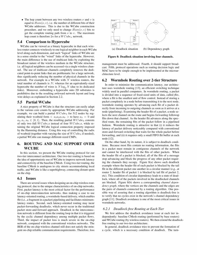
ing protocol, due to the unique characteristics of on-chip networks.First, packet latency is the most critical factor for the performanceof on-chip interconnection networks, thus making a case to uselatency-oriented routing, a wormhole-based delivery, which enablesflit (i.e., a fragment in a packet) pipelining and facilitates minimum-latency routes. Second, such latency-oriented routing may incurpacket-forwarding deadlocks, which never occur in the traditionalpacket store-and-forward approach. Deadlock in the interconnec-tion network is different from the routing loop in that it is triggeredby the cyclic channel dependency among multiple packet flows.Third, the impact of packet loss is much severe in the on-chipnetwork, compared with the conventional wireless networks. TheBER of the on-chip wireless channel still does not satisfy the strin-gent on-chip reliable communication requirements. Therefore, loss
P4
P1 P1 P2
P3
P2
P4 P3
Router 1
Buf
fer
Router 2
Router 3Router 4
c1
c2
c3
c4
.
(a) Deadlock situation
c1
c4 c2
c3
.
(b) Dependency graph
Figure 8: Deadlock situation involving four channels.
management must be addressed. Fourth, it should support broad-cast. Fifth, protocol operations such as routing decision logic andMAC have to be simple enough to be implemented at the microar-chitecture level.
6.2 Wormhole Routing over 2-tier StructureIn order to minimize the communication latency, our architec-
ture uses wormhole routing [13], an efficient switching techniquewidely used in parallel computers. In wormhole routing, a packetis divided into a sequence of fixed-sized units of data, called flits,where a flit is the smallest unit of flow control. Instead of storing apacket completely in a node before transmitting it to the next node,wormhole routing operates by advancing each flit of a packet di-rectly from incoming to outgoing channels as soon as it arrives at anode (pipelining). Examining the header flit of a packet, a node se-lects the next channel on the route and begins forwarding followupflits down that channel. As the header flit advances along the spec-ified route, the remaining flits of the packet follow in a pipelinedfashion. Wormhole routing is attractive in that (i) it reduces thelatency of packet delivery noticeably compared with conventionalstore-and-forward switching that waits for the whole packet beforeforwarding, and (ii) it requires only a small FIFO flit buffer at eachnode [12].On the other hand, by its nature, it is subject to deadlock condi-
tions. Because most flits contain no routing information, the flitsin a packet must remain in contiguous channels of the networkand cannot be interleaved with the flits of other packets. Whenthe header flit of a packet is blocked, all of the flits of a messagestop advancing and block the progress of any other packet requir-ing the channels they occupy. Figure 8(a) shows such deadlockexample where the header flit of each packet is blocked by the tailflit in the different packet one another in a circular manner (e.g., atrouter 2, header flit of packet 1 is blocked by tail flit of packet 2,etc). This condition of circular dependency leads to a state of dead-lock, where all of the packets involved in the deadlocked channelsare blocked. Figure 8(b) shows a corresponding channel depen-dency graph, where the vertices are the channels and the edges arethe pairs of channels connected by a routing algorithm. One pos-sible way of assuring that a routing algorithm is deadlock-free isto verify that no cycles exist in the network’s channel dependencygraph [11]. Deadlock avoidance is one of the most critical issues inwormhole networks.
6.2.1 Deadlock-free Routing at Each TierWe first address the deadlock avoidance issue at each tier in-
dependently: baseline CMesh routing (performed by base routers)andWCube routing (by wireless routers). We then extend the deadlock-free routing to our two-tier architecture.In general, deadlock avoidance tries to prevent the formation of
a cycle, which is a necessary condition of deadlock. The turn-
/* pkt is the packet received by wireless router νν.wcubeid = < a2n−1a2n−2 · · · a1a0 >pkt.dst.wcubeid = < b2n−1b2n−2 · · · b1b0 > */
WCubeRouting(pkt)if (pkt.nexthop == ν.wcubeid)if (pkt.dst.wcubeid == ν.wcubeid)out_port = FTableLookup(pkt.dst);forward pkt to out_port and return;
elsepkt.nexthop = < a2n−1a2n−2 · · · a1a0 >;for (i = 2n − 1; i ≥ 0; i −−)if (ai �= bi) change ai to bi in pkt.nexthop;transmit pkt and return;
else discard pkt;
Figure 9: Pseudocode for WCube deadlock-free routing.
model [18] completely avoids deadlock by making sure that theset of allowable turns made by packets in the network cannot forma cycle. A cycle in a mesh consists of several turns. As an examplein 8(a), SE (from South input channel to East output channel), ES,NW, and EN turns are essential in a clockwise cycle. Our baseline2D mesh routing uses the standard XY routing where the packetsare routed along the X dimension first, then along the Y axis totheir destination. Note that XY routing is made deadlock-free byrestricting turns from the Y dimension to the X dimension.For the WCube structure, we can ensure deadlock freedom by
employing dimension-ordered routing [11], which assigns each chan-nel a unique number and allocates packets to channels in strictlydecreasing orders along the route. In an n-level WCube, a wirelessrouter Rν has 2n logical output channels (one for each neighbor),labeled c0,ν , · · · , c(2n−1),ν . We have a total ordering of the chan-nels in the structure according to their subscript: c(2n−1),(22n−1) >c(2n−1),(22n−2) > · · · > c0,1 > c0,0. Figure 9 shows our WCuberouting algorithm. A packet arriving at wireless routerRν destinedfor wireless routerRυ is routed on channel ci,ν where i is the posi-tion of the most significant bit in which ν and υ differ. Since pack-ets are routed in the order of decreasing channel subscript, there areno cycles in the channel dependency graph, and hence our WCuberouting is deadlock free.Upon receiving a packet, the wireless router first decides whether
to forward or discard it by checking the nexthop field of the packetthat contains the wcubeid of the intended next-hop wireless routerso that other logical neighbors drop this packet immediately. Then,the wireless router compares the destination wcubeid of the packetand its own wcudeid, and decides the next hop by correcting theleft-most unmatched bit. Then, the destination wireless router for-wards the packet to the base router whose first two bits of baseidmatch those of the destination baseid of the packet by looking upthe forwarding table. Recall that only four base routers are directlyconnected to a wireless router, and the first two bits of baseid indi-cate the position of the base router from the wireless router - oneof four quadrants (see Figure 5(a)). Since at most three extra hopsbetween the wireless router and the base router are needed at boththe beginning and the end of the WCube route whose path lengthis at most 2n in aWCuben, the maximum hop count between anytwo nodes is therefore 2n + 6 in our two-tier architecture.The number of entries of the forwarding table at each wireless
router is 2n, which is the number of logical neighbors a wirelessrouter has, plus m entries for a cluster of m base routers (m = 16in our case) that the wireless router is in charge of. Thus, everywireless router has a forwarding table with 2n + m valid entries.For example, the table has only 20 entries in a 2-level WCube net-work, accommodating as many as 1024 nodes. Each entry in thetable has two fields: an out_port indicating the outgoing port num-
P6
P1
Wireless router
P2
P1
Wireless router
P3 P2
Base router
P4 P3
Base router
P5 P4
Base router
P6 P5
Base router
Buf
fer
c2c1
WCube
CMesh
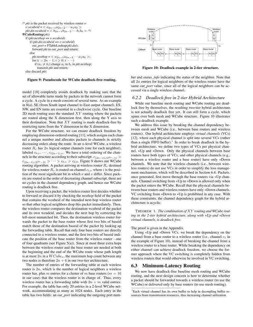
Figure 10: Deadlock example in 2-tier structure.
ber and status_info indicating the status of the neighbor. Note thatall 2n entries for logical neighbors of the wireless router have thesame out_port value, since all of the logical neighbors can be ac-cessed via a single wireless channel.
6.2.2 Deadlock-free in 2-tier Hybrid ArchitectureWhile our baseline mesh routing and WCube routing are dead-
lock free by themselves, the resulting two-tier hybrid architectureis not actually deadlock free yet. It can still form a cycle, whichspans over both mesh and WCube structure. Figure 10 illustratessuch a deadlock example.We address this issue by breaking the channel dependency be-
tween mesh and WCube (i.e., between base routers and wirelessrouters). Our hybrid architecture employs virtual channels (VCs)[12], where each physical channel is split into several VCs (ratherthan a single FIFO buffer).1 In order to break deadlock in the hy-brid architecture, we define two types of VCs per physical chan-nel, ∗Up and ∗Down. Only the physical channels between baserouters have both types of VCs, and other physical channels (e.g.,between a wireless router and a base router) have only ∗Downchannels. We note that the wireless channels (i.e., between wire-less routers) do not use VCs in order to simplify the loss manage-ment mechanism, which will be described in Section 6.4. Packets,once generated, first move through the base routers via ∗Up chan-nels. Channel switching from ∗Up to ∗Down is allowed only whenthe packet enters the WCube. Recall that the physical channels be-tween base routers and wireless routers have only ∗Down channels.VC switching from ∗Down to ∗Up is prohibited in any case. Withthese constraints, the channel dependency graph for the hybrid ar-chitecture is acyclic.
THEOREM 1. The combination ofXY routing andWCube rout-ing in the 2-tier hybrid architecture, along with ∗Up and ∗Downvirtual channels, is deadlock free.
The proof is given in the Appendix.Using ∗Up and ∗Down VCs, we break the dependency on the
channel from a base router to a wireless router (i.e., channel c1 inthe example of Figure 10), instead of breaking the channel from awireless router to a base router. While breaking the dependency oneither channel can achieve deadlock freedom, we choose the for-mer approach where the VC switching is completely hidden fromwireless routers that would otherwise be involved in VC switching.
6.3 Minimum-Latency RoutingWe now have deadlock-free baseline mesh routing and WCube
routing, and the next design concern is how to determine whethera packet should be forwarded towards a wireless router (to use theWCube) or delivered only by base routers (to use mesh routing).
1Each virtual channel has its own buffer to help in decoupling buffer re-sources from transmission resources, thus increasing channel utilization.
The latency of a packet through an interconnection network canbe expressed as the sum of the header latency Th, the serializationdelay Ts, and medium delay Tm:
T = Th + Ts + Tm = Hdr + L/W + Tm
where H is the hop count, dr is the router delay, L is the packetsize, andW is the channel bandwidth. Minimizing latency requiresestablishing careful balance between Th and Ts [24]. The conven-tional on-chip network has plentiful channel bandwidth (e.g., linkbandwidth Wmesh = 16 bytes/cycle), thus significantly reducingTs. However, 2D mesh networks fail to balance between Th andTs due to the high hop count. On the other hand, WCube has avery small hop count while the wireless channel bandwidth is notyet comparable to the wire link. According to our result in Section4, wireless link bandwidth Wwcube is 1 byte/cycle at the currentstage. Given that the average packet size L is 20 bytes2, and us-ing 5-cycle pipelined routers (i.e. dr = 5 cycles), the latency ofthe packet using only the mesh Tmesh and the latency with WCubeTmesh+wcube can each be calculated in terms of cycles: Tmesh =5Hmesh +1.25 and Tmesh+wcube = 5Hmesh+wcube +20. Hence,we can minimize latency by opportunistically using WCube whenHmesh − Hmesh+wcube ≥ 4; and in other cases, using mesh rout-ing only.Recall that we use a cluster of 4 × 4 base routers as WCube0,
and the hop count within a cluster is at most 6 (via the baselinemesh). The above criterion indicates that we do not benefit fromusing wireless shortcut within a cluster size of 4 × 4 CMesh (evenif we have multiple wireless routers in aWCube0) since we cannotsatisfy the inequalityHmesh − Hmesh+wcube ≥ 4 in any case.A routing table in each base router is statically configured based
on the above criterion, so that it has one entry per destination baserouter that needs mesh-routing only, and a single default entry forother destinations that need WCube routing. The out_port of thedefault entry connects either directly to the wireless router or to aneighbor base router closer to the wireless router. Note that we canfurther reduce the number of entries in the routing table by com-bining entries for 16 base routers with the same wcubeid into oneentry. We have a single bit per packet indicating whether to useWCube. This bit is set only by a source base router (by looking upits routing table), and always reset by wireless routers. Once this bitis set, the packet must use WCube (i.e., at each intermediate baserouter, this packet comes under the default entry towards WCubeeven if there exists an entry for the destination of this packet). Weagain note that our baseline mesh routing uses XY routing to en-sure deadlock freedom.
6.4 Loss ManagementA single message loss can cause serious performance degrada-
tion in the on-chip network, since a message itself may have somedependency on the operation of a group of different nodes (e.g.,cache coherence protocol, pipelining data flow, etc). The currentRC wires have extremely low bit-error rate (BER) of approximately10−14. Within the maximum communication distance of futureCMPs, 1.5cm, the BER of the on-chip wireless channel is less than10−9 (see Figure 3(b)), which is far higher than that of RC wires.Hence, WCube must properly manage message loss.We devise a novel and simple loss management solution inWCube.
We use a zero-signaling-overhead scheme OAR based on over-hearing on intermediate hops, and use an on-demand, checksum-based error-detection and retransmission scheme at the last hop.Overhearing-and-retransmission (OAR) detects and recovers packet
2Request messages and data messages (between cores and L2 cache banksor between cores) are 8 bytes and 32 bytes, respectively.
losses without extra signaling overhead. It exploits the interconnec-tion property of WCube. OAR does not require an explicit ACK.Rather, it utilizes the free overheard packets for loss detection. Notethat every wireless router is able to listen on all the logical neigh-bors’ transmissions via multiple receivers, and every logical linkis bidirectional, i.e. any two neighbors are mutual neighbors inWCube. For example, wireless router< 0000 > forwards a packetto < 1000 >, and when < 1000 > relays this packet to any nexthop, this packet is overheard by previous hop< 0000 > due to theWCube interconnection property. Instead of simply discarding theoverheard packet, the router checks whether the packet matchesthose in the corresponding retransmission FIFO buffer (RtFIFO).Each wireless router maintains an RtFIFO per its logical neighbor.When router i forwards a packet to j, it stores the packet into Rt-FIFO in charge of j unless j is the destinationWCube router. Whenthis packet is overheard by i and found in the RtFIFO, then all theremaining packets in the RtFIFO, if any, ahead of this packet areconsidered lost, and will be retransmitted to j and put back intothe end of the RtFIFO. Note that the lost packet(s) is retransmittedto j only by previous-hop router i, since only the original sender ihas the copy of the overheard packet in its RtFIFO. Then the over-heard packet is removed from the RtFIFO. Since WCube channelsdo not use virtual channels, packets are always forwarded in se-quence. Hence, OAR works correctly and guarantees the reliablepacket delivery using simple buffering mechanism.However, we still have not addressed the last-hop case, where
the next hop is the destination WCube router and overhearing isimpossible. OAR resolves this issue by inserting checksums (4-bitor 8-bit) into the packet, if the wireless router sees that the next hopis the destination. At the destination, the packet is verified by thechecksum. Upon checksum mismatch, the destination node sendsback a negative acknowledgment (NACK) to the sender, which sub-sequently retransmits the packet.The loss management scheme in WCube has advantages over al-
ternative solutions. Forward-error-correction (FEC) improves thewirelss channel reliability by detecting and correcting errors onthe receivers but incurs fixed overhead over every packet. In fact,several error correcting codes have been proposed for wired NoCrouters. However, the hardware implementation comes at a cost inboth encoding and decoding logics.
6.5 Broadcast SupportWe use a hierarchical approach to broadcast in WCube. We form
a spanning-tree for each source wireless router, and a spanning-tree for each source base router inside each WCube0 using the 2-Dmesh. These spanning-trees are static in nature. For each WCube0,each base router has a broadcast table with m + 1 entries. Eachentry corresponds to a base router or the wireless router as the rootof a spanning tree, and gives the next hops of the spanning tree. Foreach wireless router, it also contains a broadcast table in which eachentry also corresponds to a wireless router as the root of a spanningtree. But the entry contains a field indicating whether the wire-less router is a leaf node and a field describing the parent node ofthe wireless router. This is because wireless routers use broadcastchannels to simultaneously connect to all neighbors, and we cannotask a sender to only send to a subset of its neighbors. Instead, thereceiver must decide whether it needs to accept a packet, based onwhether or not the packet is from its parent node. The number ofentries in the table is the number of wireless routers, which againis a small number.The broadcast procedure then works as follows. When a source
core broadcasts a packet, it sends the packet to its base router, thebase router then forwards the packet to its next hops by looking up
its broadcast table. By doing so, the packet propagates along thespanning-tree in that WCube0. When a wireless router receives abroadcast packet, if the packet is internally generated or from itsparent node, it accepts the packet. Otherwise, the packet is dis-carded. If the wireless node is not a leaf node, it broadcasts thepackets to all its logical neighbors.
6.6 Wireless MACA key design requirement for wireless MAC in WCube is op-
eration simplicity, as it is implemented at the microarchitecturelevel. We cannot afford the powerful, yet sophisticatedMACmech-anisms employed in today’s conventional wireless networks, e.g.,CSMA/CA, collision avoidance, and random backoff. While someprior work on on-chip UWB interconnect [34] uses a contention-based MAC, they assume to have separate wired controlling chan-nels for arbitration among nodes.Two distinctive features for wirelessMAC inWCube are frequency-
division multiple access (FDMA) and a cross-layer design for relia-bility management. WCube MAC uses a different frequency chan-nel to deliver a packet at each wireless router. FDMA-based MACeffectively offers a dedicated link for each transmission. WCubeMAC naturally supports multicast. In WCuben, each router hasone transmitter, as well as 2n receivers each of which tunes to adifferent frequency channel. Thus, each transmission is receivedby all 2n receivers, each at 2n logical neighbors in different levels.The reliability management for data transmissions in WCube MACtakes a cross-layer, on-demand approach. It receives informationfrom the network-layer routing protocol at the router, regardingwhether it is an intermediate hop or the last hop over WCube. Itinvokes overhearing, which incurs zero signaling overhead, as anintermediate-hop delivery. If it acts as the last hop, it will send aMAC-layer NACK when the router detects checksum errors in thepacket at the network layer. In this way, wireless MAC in WCubereduces the signaling and communication overheads in reliabilitymanagement.
7. EVALUATIONIn this section, we evaluate the performance of our two-tier hy-
brid architecture in a 1000-node on-chip network. We use Garnet[17], a detailed on-chip interconnect network model simulation in-frastructure that enables system-level performance and power mod-eling of network-level technique. Garnet models the detailed fea-tures of a state-of-the-art network such as 5-stage pipeline routerdesign with wormhole switching, and it also includes the Orion
Parameter SettingTechnology 32nmClock frequency 2 GHzNumber of cores on chip 1024Number of processing cores 768Number of L2 Caches 240 banksNumber of DRAM interfaces 16Switching technique WormholeBaseline topology 4-way concentrated meshBaseline mesh routing XY routingBaseline link bandwidth 16/8/4 bytes/cycleWireless link bandwidth 1 byte/cycleNumber of virtual channels 8 VCsNumber of wireless routers 16Number of antennas in wireless router 1 TX / 4 RX antennasWireless backbone structure 2-level WCubeSize of WCube0 16 base routers (64 nodes)
Table 2: Simulation parameters
0
10
20
30
40
50
60
70
80
Uniform UniDF BiDF HotBiDF 1Hotspot 2Hotspot 4Hotspot
Ave
rage L
ate
ncy (
cycle
s)
16B Baseline CMesh 2-tier Architecture (16B Baseline)
2-tier Architecture (8B Baseline) 2-tier Architecture (4B Baseline)
`
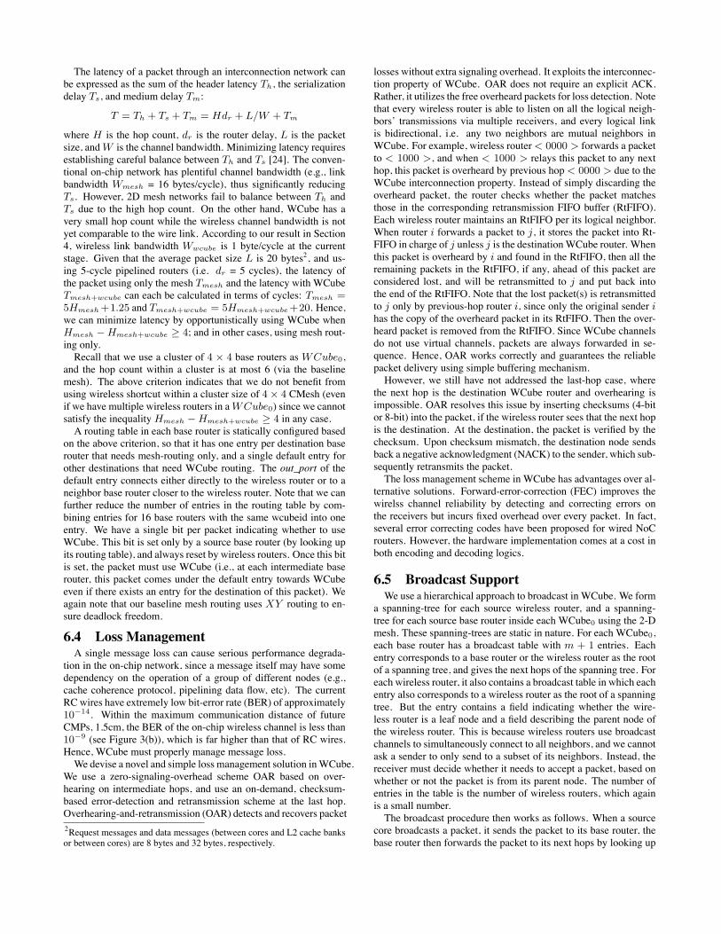
Figure 11: Latency reduction.
0
2
4
6
8
10
12
Uniform UniDF BiDF HotBiDF 1Hotspot 2Hotspot 4Hotspot
Avera
ge N
um
ber of
Hops .
16B Baseline CMesh 2-tier Hybrid Architecture
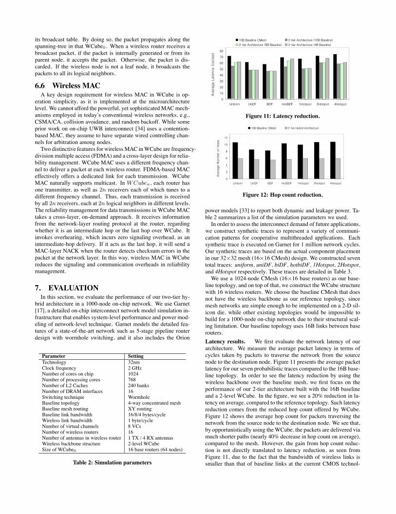
Figure 12: Hop count reduction.
power models [33] to report both dynamic and leakage power. Ta-ble 2 summarizes a list of the simulation parameters we used.In order to assess the interconnect demand of future applications,
we construct synthetic traces to represent a variety of communi-cation patterns for cooperative multithreaded applications. Eachsynthetic trace is executed on Garnet for 1 million network cycles.Our synthetic traces are based on the actual component placementin our 32×32 mesh (16×16 CMesh) design. We constructed seventotal traces: uniform, uniDF, biDF, hotbiDF, 1Hotspot, 2Hotspot,and 4Hotspot respectively. These traces are detailed in Table 3.We use a 1024-node CMesh (16×16 base routers) as our base-
line topology, and on top of that, we construct the WCube structurewith 16 wireless routers. We choose the baseline CMesh that doesnot have the wireless backbone as our reference topology, sincemesh networks are simple enough to be implemented on a 2-D sil-icon die, while other existing topologies would be impossible tobuild for a 1000-node on-chip network due to their structural scal-ing limitation. Our baseline topology uses 16B links between baserouters.
Latency results. We first evaluate the network latency of ourarchitecture. We measure the average packet latency in terms ofcycles taken by packets to traverse the network from the sourcenode to the destination node. Figure 11 presents the average packetlatency for our seven probabilistic traces compared to the 16B base-line topology. In order to see the latency reduction by using thewireless backbone over the baseline mesh, we first focus on theperformance of our 2-tier architecture built with the 16B baselineand a 2-level WCube. In the figure, we see a 20% reduction in la-tency on average, compared to the reference topology. Such latencyreduction comes from the reduced hop count offered by WCube.Figure 12 shows the average hop count for packets traversing thenetwork from the source node to the destination node. We see that,by opportunistically using theWCube, the packets are delivered viamuch shorter paths (nearly 40% decrease in hop count on average),compared to the mesh. However, the gain from hop count reduc-tion is not directly translated to latency reduction, as seen fromFigure 11, due to the fact that the bandwidth of wireless links issmaller than that of baseline links at the current CMOS technol-
0
1
2
3
4
Uniform UniDF BiDF HotBiDF 1Hotspot 2Hotspot 4Hotspot
NoC
Pow
er (W
atts)
16B Baseline CMesh 2-tier Architecture (16B Baseline)
2-tier Architecture (8B Baseline) 2-tier Architecture (4B Baseline)
`
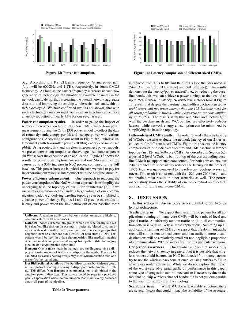
Figure 13: Power consumption.
ogy. According to ITRS [21], gain frequency fT and power gainfmax will be 600GHz and 1 THz, respectively, in 16nm CMOStechnology. As long as the carrier frequency increases at each newgeneration of technology, the number of available channels in thenetwork can scale up, thus increasing the overall network aggregatedata rate, and improving the on-chip wireless channel bandwidth upto 8 bytes/cycle. We have confirmed (results not shown) that withsuch a technology improvement, our 2-tier architecture can achievea latency reduction of nearly 45% for our seven traces.
Power consumption results. In order to gauge the impact ofwireless interconnect on future 1000-core CMPs, we perform powermeasurements using the Orion [33] power model to collect the dataof router dynamic energy per flit and leakage power with variousconfigurations. According to our result in Figure 3(b), wireless in-terconnect (with transmitter power -10dBm) energy consumes 4.5pJ/bit. Using router, link and wireless interconnect power models,we present power-consumption as the average instantaneous power(in Watts) over the execution of an application. Figure 13 shows theresults for power consumption. We see that our 2-tier architecturecauses up to a 35% increase in NoC power, compared to the 16Bbaseline. This power increase is indeed the cost we need to pay forincorporating our wireless interconnect with the baseline structure.
Power efficiency enhancement. One approach to reducing thepower consumption of the NoC with our approach is to simplify theunderlying baseline topology of our 2-tier architecture [8]. If weuse wireless interconnect to handle a large volume of our commu-nication load, the underlying baseline topology can be simplified toenhance power efficiency. Figures 11 and 13 provide the results onlatency and power when the link bandwidth of our baseline mesh
Uniform: A random traffic distribution - nodes are equally likely tocommunicate with all other nodes.Dataflow: nodes clustered into groups which are functionally laid outin a dataflow-like fashion on our mesh. nodes are biased to commu-nicate with nodes within their group and with nodes in groups thatneighbor them on either one side (UniDF) or both sides (BiDF). Thispattern would be seen in a data decomposition like medical imagingor a functional decomposition into a pipelined pattern (like an imagingpipeline or a cryptographic algorithm).Hotspot: One or more nodes in the mesh are sending/receiving a dis-proportionate amount of traffic - a hotspot in the mesh. This can beexhibited by caches holding frequently used synchronization vars or amaster/worker paradigm.Hot Bidirectional Dataflow: TheDataflow pattern but with one groupin the quadrant sending/receiving a disproportionate amount of traf-fic. This differs from Hotspot as communication is still biased in thedataflow pattern direction. This pattern could be seen in a pipelinedparallel application where communication load is not evenly balancedacross all parts of the pipeline.
Table 3: Trace patterns
0
10
20
30
40
50
60
70
Uniform UniDF BiDF HotBiDF 1Hotspot 2Hotspot 4Hotspot
Ave
rage L
ate
ncy (
cycle
s)
CMesh (768 cores) 2-tier Architecture (768 cores)
CMesh (512 cores) 2-tier Architecture (512 cores)
`
Figure 14: Latency comparison of different-sized CMPs.
is reduced from 16B to 8B and then to 4B (see the bars noted as2-tier Architecture (8B Baseline) and (4B Baseline)). The resultsdemonstrate the latency/power tradeoff, i.e., by reducing the base-line bandwidth, we can achieve a power savings at the cost of anup to 25% increase in latency. Nevertheless, a closer look at Figure11 reveals that despite the baseline bandwidth reduction, our 2-tierarchitecture still has lower latency than the 16B baseline mesh forall seven probabilistic traces, while it can save power consumptionby up to 35%. The results show that our 2-tier architecture builtwith the baseline mesh and WCube structure effectively reduceslatency, while network energy consumption can be minimized bysimplifying the baseline topology.
Different-sized CMP results. In order to verify the adaptabilityof WCube, we also evaluate the network latency of our 2-tier ar-chitecture for different-sized CMPs. Figure 14 presents the latencycomparison of our 2-tier architecture and 16B baseline referencetopology in 512- and 768-core CMPs. As described in Section 5.5,a partial 2-level WCube is built on top of the corresponding base-line CMesh to support such core counts. For both core counts, our2-tier architecture successfully reduces the latency on the order of18-25% on average, compared to the reference topology across alltraces. This result is consistent with the 1024-core CMP result, andwe obtain similar results in other scenarios as well. The perfor-mance study shows the viability of our 2-tier hybrid architecturalapproach for future many-core CMPs.
8. DISCUSSIONIn this section we discuss other issues relevant to our two-tier
hybrid architecture.
Traffic patterns. We expect the overall traffic pattern for all ap-plications running on many-core CMPs will be a mix of local andglobal traffic. A uniformly random traffic or all-to-all communica-tion pattern is very unlikely in most applications. Summing up allapplications running on CMPs, we expect that the dominant trafficseen will still be sent to local cores, and that traffic to more distantdestinations will be a relatively small but non-negligible proportionof communication. WCube works best for this particular scenario.
Congestion awareness. Our two-tier architecture successfullyreduces the network latency in general, but it is possible that wire-less routers could become an NoC bottleneck if too many packetstry to use the wireless backbone at once, causing buffers to fill upat wireless router entrances. While we do not explore the impactof the worst-case adversarial traffic on performance in this paper,some type of congestion control mechanism is necessary due to thefact that on-chip wireless channel bandwidth is not yet comparableto the wire link at the current technology.
Scalability issue. While WCube is a scalable structure, thereare several factors that could impact the scalability of the structure.
One prominent concern is about the receive antenna spacing at eachwireless router. In an n-level WCube, each wireless router has 2nreceivers. As the core count grows, the number of receive anten-nas increases and thus, antenna spacing within each wireless routerwill reduce with n, which may cause inter-channel interference.However, we believe that there will be a practical upper boundon future CMP core count (e.g., high hundreds, low thousands ofcores) [5, 22]. In practice, a WCube with a small level (e.g., n=3)can accommodate as many as several thousands of cores.
Alternative interconnect structure. One future direction to fur-ther enhance network performance is to build a wireless intercon-nect on top of the RF-I transmission lines. Since RF-I achieveslatency reduction by offering shortcuts in mid-sized networks (inthe range of tens to lower hundreds of cores) [8], it can bridge thegap between the baseline mesh and our wireless interconnect. Withthree levels of hierarchy, local messages would go through the base-line RCwires (e.g., within aWCube0), mid-range messages wouldbe forwarded via RF-I transmission lines that span over multipleWCube0s, and only the long-range messages would be deliveredusing wireless interconnects. Our work in this paper serves as thebasis for this future direction.
9. CONCLUSIONIn this paper, we make a case for using a two-tier wireless and
wired architecture to interconnect hundreds to thousands of coreson a system-on-chip. The wireless express way eliminates longwires and reduces latency for long-haul, many-hop, inter-core com-munication in a way that is not possible with today’s wired inter-connect technology. To this end, we propose a recursive, wire-less interconnect structure called the WCube, which features a sin-gle transmit antenna and multiple receive antennas at each microwireless router and offers scalable performance in terms of latencyand connectivity. We further devise a new wormhole-based, two-tier routing algorithm that is deadlock free and ensures minimum-latency route. The early evaluation result of a 20 ∼ 45% latencyreduction is also quite significant from the CMP interconnect per-spective.Designing wireless interconnect at the microarchitecture level
also opens new research opportunities for the wireless networkingcommunity. The miniature antenna, together with simple transceivercircuits, enables us to build multiple transmitters, and/or multiplereceivers at each micro wireless router. This enables the applica-tion and deployment of many cooperative wireless communicationand networking techniques. The 100 − 500 GHz, sub-terahertzfrequency band does not require sophisticated transceiver design toachieve high data rates of 10s of Gbps. But operation simplicity is akey requirement for microarchitectures. All of these make cases fornew wireless networking solutions efficiently operating and sharingin the frequency domain.
10. ACKNOWLEDGMENTSWe greatly appreciate the insightful comments by our shepherd,
Dr. David Wetherall and the anonymous reviewers for their con-structive feedback. This work was supported in part by SRC grant#1796, and the U.S. Army Research Laboratory and the U.K. Min-istry of Defense under Agreement Number W911NF-06-3-0001.
11. REFERENCES[1] V. Agarwal, M. S. Hrishikesh, S. W. Keckler, and D. Burger. Clock rate versus
IPC: the end of the road for conventional microarchitecture. ISCA-27, 2000.[2] J. Andrews and N. Backer. Xbox360 system architecture. Hot Chips, 2005.
[3] Ansoft Corporation. High Frequency Structure Simulator (HFSS).http://www.ansoft.com/products/hf/hfss/
[4] K. Asanovic et al. The landscape of parallel computing research: a view fromBerkeley. Technical Report, UCB/EECS-2006-183.
[5] S. Borkar. Thousand core chips: a technology perspective. DAC, 2007.
[6] L. A. Barroso et al. Piranha: a scalable architecture based on single-chipmultiprocessing. ISCA-27, 2000.
[7] M.-C. F. Chang et al. CMP network-on-chip overlaid with multi-bandRF-Interconnect. HPCA, 2008.
[8] M.-C. F. Chang et al. Power reduction of CMP communication networks viaRF-Interconnects. MICRO, 2008.
[9] D. Choudhury, J. Foschaar, R. Bowen, M. Mokhtari. A 70+GHz BW packagefor multigigabit IC applications. Microwave Symposium Digest, June 2004.
[10] S. Boyd-Wickizer et al. Corey: an operating system for many cores. OSDI,2006.
[11] W. Dally and C. Seitz. Deadlock-free message routing in multiprocessorinterconnection networks. IEEE Trans. on Computers, 1987.
[12] W. Dally. Virtual-channel flow control. IEEE Trans. on Parallel and DistributedSystems, 1992.
[13] W. Dally. Wire efficient VLSI multiprocessor communication networks. Proc.Stanford Conf. Advanced Research VLSI, 1987.
[14] D. Huang et al. Terahertz CMOS frequency generator using linear superpositiontechnique. IEEE Journal of Solid State Circuits, Dec 2008.
[15] A. Duller, G. Panesar, and D. Towner. Parallel Processing - the picoChip way!.Communicating Process Architectures, 2003.
[16] B. A. Floyd. Intra-chip wireless interconnect for clock distribution implementedwith integrated antennas, receivers, and transmitters. IEEE JSSC, 2002.
[17] N. Agarwal et al. Garnet: A detailed interconnection network model inside afull-system simulation framework. TR CE-P08-001, Princeton University, 2007.
[18] C. J. Glass, L. M. Ni. The turn model for adaptive routing. ISCA-19, 1992.
[19] A. Ghuloum, Unwelcome advice from Intel.blogs.intel.com/research/2008/06/unwelcome_advice.php
[20] B. Grot and S. W. Keckler. Scalable on-chip interconnect topologies. 2ndWorkshop on Chip Multiprocessor Memory Systems and Interconnects, 2008.
[21] International technology roadmap for semiconductors, 2007 edition.http://www.itrs.net/Links/2007ITRS/2007_Chapter/ 2007_Wireless.pdf
[22] D. N. Jayasimha, B. Zafar, Y. Hoskote. On-chip interconnection networks: whythey are different and how to compare them. Technical Report, Intel Corp, 2006
[23] J. Kahle, M. Day, H. Hofstee, C. Johns, T. Maeurer and D. Shippy. Introductionto the Cell multiprocessor. IBM Journal of Research and Development, 2005.
[24] J. Kim, J. Balfour, and W. Dally. Flattened butterfly topology for on-chipnetworks. MICRO, 2007.
[25] G. Koch. Intel’s road to multi-core chip architecture.www.intel.com/cd/00/00/22/09/220997_220997.pdf
[26] NVIDIA Quadro FX 5600.http://www.nvidia.com/docs/IO/40049/quadro_fx_5600_datasheet.pdf
[27] NVIDIA Tesla C1060.http://www.nvidia.com/docs/IO/56483/ Tesla_C1060_boardSpec_v03.pdf
[28] K. Olukotun and L. Hammond. The future of microprocessors. ACM QUEUEMagazine, September 2005.
[29] K. Olukotun, L. Hammond, and J. Laudon. Chip multiprocessor architecture:techniques to improve throughput and latency.Morgan & Claypool, 2007.
[30] S. -W. Tam et al. A simultaneous tri-band on-chip RF-Interconnect for futurenetwork-on-chip. VLSI Symposium, 2009.
[31] E. Seok et al. A 410GHz CMOS push-push oscillator with an on-chip patchantenna. ISSCC, 2008.
[32] S. Vangal et al. An 80-tile 1.28 TFLOPS network-on-chip in 65nm CMOS.IEEE ISSCC, 2007.
[33] H. -S. Wang et al. Orion: a power-performance simulator for interconnectionnetworks. Int’ Symposium on Microarchitecture, 2002.
[34] D. Zhao and Y. Wang. SD-MAC: design and synthesis of a hardware-efficientcollition-free QoS-aware MAC protocol for wireless network-on-chip. IEEETransactions on Computers, Vol.57, No.9, September 2008.
APPENDIXA. Proof of Theorem 1
PROOF. A routing algorithm is deadlock-free if the network channelscan be enumerated such that the algorithm always routes the packets alongthe channels with strictly decreasing numbers. We label each channel inthe network as follows: (1) for each base router Ri, label k output ∗Upchannels c∗U
2,0,i, · · · , c∗U2,k−1,i, and label l output ∗Down channels c∗D
0,0,i,
· · · , c∗D0,l−1,i; (2) for each wireless router Ri, labelm output logical chan-
nels cW1,0,i, · · · , cW
1,m−1,i. Since our mesh routing and WCube routing
use channel ordering, each of c∗U2,j,i, c∗D
0,j,i, and cW1,j,i (∀i, j) is indepen-
dently deadlock free. Now, by our channel labeling, c∗U2,j,i > cW
1,j,i >
c∗D0,j,i , ∀i, j. Thus, our 2-tier routing is deadlock free.