Embed Size (px)
Citation preview

LCI METHODOLOGYAND DATABASES
A scalable life cycle inventory of an electrical automotive tractionmachine—Part II: manufacturing processes
Anders Nordelöf1 & Anne-Marie Tillman1
Received: 15 July 2016 /Accepted: 23 March 2017 /Published online: 9 April 2017# The Author(s) 2017. This article is published with open access at Springerlink.com
AbstractPurpose A scalable life cycle inventory (LCI) model of a per-manent magnet electrical machine, containing both design andproduction data, has been established. The purpose is to contrib-utewith new and easy to use data for life cycle assessment (LCA)of electric vehicles by providing a scalable mass estimation andmanufacturing inventory for a typical electrical automotive trac-tion machine. The aim of this article (part II of two publications)is to present the manufacturing data with associated collectionprocedures, from material constituents to complete motor.Another objective is to explain the gate-to-gate system bound-aries and the principles for linking the LCI model upstream, todatabase data, in order to create a full cradle-to-gate dataset.Methods Data for design and production of electrical machineshas been compiled from books, scientific papers, benchmarking
literature, expert interviews, various specifications, factory re-cords, and a factory site visit. For the manufacturing part, newprimary data was collected directly from industry, with a motorfactory and a steel mill in Sweden as main contributors, andfrom technical literature. Other LCA publications were used, ifpresented in sufficient detail to be disaggregated and revised, tomatch the gaps of the model. The data represents the currentlevel of technology and targets high-volume manufacturing tothe largest extent possible. Also, flows crossing the systemboundary have a recommended link to Ecoinvent data, or arequest for an attentive selection of input data, depending onthe user’s object of study. A distinction was made between theregular and an extended system boundary, wherein the process-ing of some smaller subparts was accounted for through pro-posals of ready-made Ecoinvent activities for production efforts.Results and discussion An extensive new dataset representingelectrical machine manufacturing is presented, and, togetherwith the estimation of motor mass and configuration of articlepart I, it forms a comprehensive scalable LCI model of a typicalautomotive electric traction motor. New production data in-cludes a complete motor factory, electrical steel production,and the fabrication of a neodymium-dysprosium-iron-boron(Nd(Dy)FeB) magnet. In addition, smaller, new datasets coverthe composition of silicon steel, the making of electrolytic iron,enameling of copper wire, and die casting of aluminum.Conclusions Successful data generation required Bdatabuilding^ from multiple sources and access to expert support.Transparent, well-explained, and disaggregated data recordswere found to be crucial for LCA data validation and usefulness.
Keywords Die casting . Dysprosium . Electric . Electrical .
Electrical steel . Inventory . Life cycle assessment .Machine .
Magnet . Manufacturing .Model . Motor . NdFeB .
Neodymium . Permanent . Production . Scalable . Siliconsteel
Responsible editor: Zbigniew Stanislaw Klos
PreambleThis series of two articles presents a new scalable life cycle inventory(LCI) data model of an electrical automotive traction machine, availableto download from the CPM database of the Swedish Life Cycle Center.Part I describes how the LCImodel was established and the type of resultsit provides, including the underlying permanent magnet synchronous ma-chine (PMSM) design and the structure of the LCI data model. Part IIpresents new primary production data and revised literature data to coverthe complete PMSM motor manufacturing chain, including magnet fab-rication, electrical steel production, and a comprehensive survey of anelectrical motor factory. It also discusses the data collection methodsand explains the selection of system boundaries and how to link thegate-to-gate inventory to the Ecoinvent database version 3.
* Anders Nordelö[email protected]
1 Department of Energy and Environment, Division of EnvironmentalSystems Analysis, Chalmers University of Technology,412 96 Gothenburg, Sweden
Int J Life Cycle Assess (2018) 23:295–313DOI 10.1007/s11367-017-1309-8
1 Introduction
1.1 Background
Life cycle assessment (LCA) of electrified vehicles for roadtransport, for example, plug-in hybrid or fully electric passen-ger cars, is an active research area where many case studies areconducted and published (Hawkins et al. 2012; Nordelöf et al.2014). However, few well-populated and transparent invento-ry datasets have been published for electric vehicles and dif-ferent electric powertrain components. This relates both to thecomposition of materials in the components and their produc-tion processes (Hawkins et al. 2012). Inventory data for ver-sion 3 of the Ecoinvent database, the most used and acknowl-edged life cycle inventory database worldwide (Weidemaet al. 2013), has been published by Del Duce et al. (2016)for various components of an electric powertrain such as anelectric motor and different types of power electronic devices,including production. However, some of these datasets arehighly simplified, for example, the production of permanentmagnets, a key subpart in permanent magnet synchronouselectrical machines (PMSMs). This production is approximat-ed with the data of aluminum production in the Ecoinventdatabase. In conclusion, there is a general need for more thor-ough investigation of vehicle production data (Del Duce et al.2016; Hawkins et al. 2012).
Furthermore, few life cycle assessment studies of electricalmachines have been published, this being especially apparentregarding focus on electric vehicle propulsion (Hernandezet al. 2017). Nevertheless, Hernandez et al. (2017) presentone such study. The energy data used for motor manufacturinghas been estimated from an environmental production decla-ration of a different type of electrical machine, applicable forindustrial use (ABB 2002; Hernandez et al. 2017). In fact,ABB (2002) is also the original data source for the electricmotor production data included in the Ecoinvent database(Habermacher 2011; Weidema et al. 2013; Del Duce et al.2016). The validity of this estimation for PMSM manufactur-ing is difficult to assess, but the data is considered to be out-dated by ABB representatives (Arnell 2012; Överstam 2013).Also, wastes and emissions from motor factories other thanthose coupled to energy use have not been included.
Permanent magnets are a key component in PMSMs, andneodymium-iron-boron (NdFeB) magnets are the most com-mon type used in electrical traction machines (Lucas et al.2015). Pioneering data collection and compilation for such amagnet has been conducted by Sprecher et al. (2014a, 2014b).However, magnet production procedures are complex andextensive work is required to survey all process steps indetail. Both Hernandez et al. (2015a, 2017) and Sprecheret al. (2014a, 2014b) assume iron with high carbon contentto be required for magnet fabrication, but unlike many otheriron-containing products, elemental iron of high purity is
required for the production of NdFeB magnets, such as elec-trolytic iron (Croat 1992; McCallum and Branagan 1996;Zakotnik and Tudor 2015). Hence, several processing stepsare left out of both these analyses, which would possibly alterend results for the environmental load of the magnets. In ad-dition, further advanced processing of NdFeB magnets is of-ten conducted to make them suitable for automotive operatingconditions, for example, adding dysprosium (Brown et al.2002; Vaimann et al. 2013; Yan et al. 2010), which has notbeen covered by any of the mentioned studies.
Furthermore, production procedures for electric powertraincomponents are under development. They are still immature,and often take place in small series, compared to other vehicleparts (Nordelöf et al. 2014). At the same time, the relativeimportance of manufacturing, compared to the vehicle usephase, increases with vehicle electrification (Nordelöf et al.2014). In conclusion, there is a lack of comprehensive inven-tory production data for electrical machines in automotivetraction applications.
1.2 The purpose of a scalable life cycle inventory model
The purpose of the scalable life cycle inventory (LCI) model isto provide mass composition data and manufacturing data fora typical electrical machine design for automotive tractionapplications, especially for all-electric driving with a singlemotor. The intention is to complement the few existingdatasets, and assist LCA evaluation of electric powertrains,through the generation of data for different sized machines.
The model was established as a response to the general lackof data for LCA of electrified powertrains and more specifi-cally for electrical traction machines. It contains both designand production data and generates data on motors ranging inpower from 20 to 200 kW and in torque from 48 to 477 Nm,i.e., from a small electric passenger vehicle up to, for example,a small electrically propelled city bus or truck (Volvo 2015).The resulting datasets represent the gate-to-gate production ofthe motor, from materials to complete motor, to be used as anestimate of any PMSM designed for electric propulsion, if itfalls within the range for power and torque requirements forwhich the model is valid. Other, adjacent powertrain compo-nents, i.e., the motor controller or a gearbox, are not included.The inventory model is available as a spreadsheet file inMicrosoft Excel, which can be downloaded from theSPINE@CPM LCA Database,1 together with an extensivemodel report (Nordelöf et al. 2016). The model report pro-vides relevant electrical machine theory summarized forLCA practitioners, along with all the details on how the datamodel has been established in terms of motives for design
1 Provided by the Swedish Life Cycle Center at http://cpmdatabase.cpm.chalmers.se/Scripts/sheet.asp?ActId=JT-2016-06-21-39
296 Int J Life Cycle Assess (2018) 23:295–313

selections and other model assumptions, and descriptions ofthe data collection.
Another aim has been to collect and present newmanufacturing data with sufficient resolution to identify theeffect of change in motor size within production, especially atthe motor factory. Hence, in addition to being used as a part ofthe overall data model, manufacturing data can be used inde-pendently, in both cases, to conduct LCA and pinpoint keyenvironmental issues with focus on this life cycle stage.
Finally, an important objective has been to make the modeleasy to use by LCA practitioners. For this reason, themanufacturing processes have been followed upstream to apoint where LCI data for representative material productionexist in the Ecoinvent database version 3 (Weidema et al. 2013).
1.3 Aim and content of the article series
The aim of this part of the publication, article part II, is topresent new primary production data for PMSM motormanufacturing, electrical steel production, die casting of alumi-num housings, and enameling of copper wire and to discussdata collection procedures. A description of data for permanentmagnet production chain is also included, based on previouslypublished inventory data for LCA (Sprecher et al. 2014a, b;NETL 2014a, b, 2015), but revised and updated with originaldata to match the neodymium-dysprosium-iron-boron(Nd(Dy)FeB) type used in automotive applications.Additionally, this final article (part II) explains the selection ofsystem boundaries and the principles behind the recommenda-tions for linking the gate-to-gate inventory model to Ecoinvent3 in order to create a full cradle-to-gate dataset.
As a complement, part I of the article explains the under-lying electrical machine design and the general methodologyand structure of the LCI data model. The design data collec-tion and calculations are described, together with a presenta-tion and an evaluation of the mass estimation results that themodel provides.
The level of technical detail throughout both publicationswas selected to address a broad target group including LCApractitioners novel to electric motor terminology, as well aselectrical power engineers aiming to use LCA results. For fullexplanations on the presented manufacturing procedures, de-tailed descriptions of all data collection, including assump-tions and calculations, and all tables with specifications fordata sources and recommendations for how to link withEcoinvent 3 for each flow, please read the model report(Nordelöf et al. 2016).
2 Methods
The LCI model work entailed many important procedural andmethodological considerations. The focus here is set on the
manufacturing part of the model, which are the collection ofraw data, the scope of the established gate-to-gate LCI includ-ing the aspect of design scaling, the use of Ecoinvent forbackground data, and the representativity of the study, e.g.,technically and geographically.
2.1 Data collection
The manufacturing data included is to a large extent new orig-inal data, either collected directly from industry or from tech-nical literature. Industry data was gathered in the form ofexpert interviews, site visit notes, energy audit measurements,hourly power supply figures, purchase information, permitsand machine specifications, and complemented with informa-tion from instruction films, standards, and textbook descrip-tions. Data from other LCA publications and LCI datasets wasalso included when sufficient detail was presented to disag-gregate, complement, and revise it to match the gaps of themodel.
More specifically, motor factory data was collected for theproduction procedures of another electrical machine type, aninduction machine, at ELMO Malmköpings MekaniskaWerkstad AB in Flen, Sweden (Walter 2015, 2016). The pro-cess flow was then adjusted to become representative forPMSMmanufacturing by complementing with data from oth-er productions sites (Hendershot 2015; Magnusson 2016) andother equipment (Willard 2015; Xue 2015). Data for electricalsteel production was delivered by Surahammars Bruk AB(Lindenmo 2012, 2015), a steel mill in Sweden. Technicalliterature and documentation was used to establish unit pro-cesses for die casting of aluminum (Roberts 2003; Dalquistand Gutowski 2004; Heinemann 2016), the purification ofiron (necessary for magnet fabrication) (Oeters and Ottrow2012; Schlesinger and Paunovic 2010), and coating of magnetwire (enameling) (MAG 2016; Polynt Composites 2015).Data from another LCI database, the NETL (2015) unit pro-cess library, was included unrevised for the reduction of rareearth oxides to rare earth metals (NETL 2014b), in the magnetfabrication production chain.
For the fabrication of magnets, recently published datafrom NETL (2014a) and Sprecher et al. (2014a, 2014b), aboutregular NdFeB magnets, was used as a starting point.However, some errors were corrected and the data wasreworked to become representative for an NdFeBmagnet withdysprosium content, Nd(Dy)FeB, which is suitable for auto-motive traction applications.
2.2 Functional unit, system boundaries, and adaptionof the inventory to the scalability of the design
The LCImodel presents a gate-to-gate LCI, for one permanentmagnet electrical machine with explicit power and torque re-quirements, intended for vehicle propulsion. No use or end-of-
Int J Life Cycle Assess (2018) 23:295–313 297

life treatment is included. The inventory can be combinedwith input data for recycled as well as virgin raw materials,and the upstream system boundary is located where existingdatasets for the production of materials are available inEcoinvent version 3 (Weidema et al. 2013). The technicalsystem boundaries of the model are shown in Fig. 1.
No specific geographic boundary has been defined for thevarious production steps of the model. The intention was tokeep the model as flexible as possible for the user and repre-sentative on a global level. For example, all input electricityhas been marked as Boptional^ for the user in terms of theproduction source or market mix. Still, the geographical loca-tion of a factory can sometimes implicate more or less auto-mation versus handwork. In this aspect, the LCI model repre-sents high-volume production in a factory of an industrialized
country. The representativity of the data is further discussed inSect. 2.4.
In addition, given the focus on scaling of the motor designthroughout both articles in this series, it is important to pointout that the modeled LCI does not take different scales ofproduction volume or market penetration into consideration.However, efforts were made to match the design scaling prop-erly with the manufacturing model. Hence, although the LCImodel was built with conventional unit processes, the level ofdetail allows for a correct account of the function in eachproduction step. For example, the energy used in welding ofthe rotor stack is calculated from its length, while the amountof spill from stamping in the previous step is calculated bymass. Sometimes, machining of smaller parts generate rela-tively more spill than large parts, for example, if they have the
Fig. 1 Overview of the technicalsystem boundaries for thecollected production data,including different maininformation sources and how theLCI model relates to theEcoinvent 3 database (Weidemaet al. 2013)
298 Int J Life Cycle Assess (2018) 23:295–313

same tolerances in absolute numbers. Such an increased ac-count of spill with decreased size of the subpart was includedfor the housing. As a consequence, the model often keepstrack of more than one parameter in the flows between pro-cesses, for example, mass, surface area, and length incombination.
In terms of time, both design and manufacturing data havebeen judged as representative for the current level of technol-ogy. All data measured from industry has been collected with-in the last 5 years. Most textbooks, research articles, and tech-nical reports are from the same time period or at least pub-lished within the last 10 years. However, in some cases, liter-ature sources are older due to the lack of new data.
No transportation of goods has been included in the model.Instead, the user is expected to add subpart transportation ifthis is relevant to the study in which the LCI model is used.
2.3 Linking the model to Ecoinvent
The gate-to-gate LCI requires input of materials, energy, andprocessing agents, in various stages of processing. Next to theproduct, output is generated in the form of emissions andwastes. To make the model user-friendly, each such flow cross-ing the system boundary has been given a recommendation fora Blinked flow^ representation in Ecoinvent version 3 (markedas E3 in the model report), unless the user is called on to make amore attentive selection (marked as optional in the model fileand report), for example, for the use of electricity in production.
Furthermore, as shown in Fig. 1, a distinction was madebetween the regular system boundary (the technical boundaryreferred to so far) and an extended system boundary, whichencircles a set of Ecoinvent activities for material transforma-tion and coating. These extended boundary activities are in-cluded in the LCI model file, but listed separately from thecharted gate-to-gate inventory with the regular boundaries, asa recommendation for how to account for the making of sev-eral subparts from their material constituents.
The reason for this is that Ecoinvent production efforts aregiven in analogous form for services which reshape 1 kg ofinput rawmaterial or semi-finished product into 1 kg of outputproduct (Hischier 2007; Steiner and Frischknecht 2007;Classen et al. 2009). In the representation of metal forming,conversion of plastics, and average machine working ofmetals, the amount of materials removed and scrapped areincluded as inflow and outflow in activities, along with otherauxiliaries and emissions, but not the materials and productsbeing reshaped. Accordingly, the reference flow of the processrefers to the activity and not the output product. This is alsothe case when the reference flow unit is expressed as a mass,e.g., the description of Bhot rolling^ in Classen et al. (2009).Hence, a setup featuring a separate activity list and extendedsystem boundary was selected to avoid confusion and to sep-arate the recommendations for Ecoinvent representation of
linked flows from the actual inventory within the regular sys-tem boundaries. Users of the LCI model should be aware thatthese production efforts are not defined in a consistent manner.For more specifics about the differences, we refer to the orig-inal Ecoinvent reports (Hischier 2007; Steiner andFrischknecht 2007; Classen et al. 2009).
Ecoinvent coating processes for galvanization and tin platingare formulated in similar fashion to the material transformationprocesses (Weidema et al. 2013). They also relate only to theactual process and do not include the material being treated; i.e.,the reference flow is a layer of coating of a certain thickness,expressed per surface area, and not a coated product. Hence,they have been included in the list of activities outside the reg-ular system boundary, but inside the extended system boundary.
Lastly, the choice of linking inputs and outputs to theEcoinvent database enabled us to make a qualitative uncer-tainty assessment of the inventory data according to theEcoinvent pedigree matrix (Weidema et al. 2013) and to quan-tify standard deviations on the unit process level for users whowish to include uncertainty assessment based on error propa-gation using computational mathematics.
2.4 Representativeness of studied manufacturingprocedures
There can be many different techniques used in manufacturingthe same machine part. Several aspects are taken into consider-ation when selecting a specific method, such as cost-efficiency,productivity, and cycle time; geometry and strength of the part;surface finishing and material properties; and environmentalhazards (Tong 2014). For example, when producing large vol-umes of aluminum housing parts, die casting is a suitablemanufacturing method. But for lower volumes of a few hun-dred samples, or in the case of prototypes, cutting, drilling,milling, and turning directly from a solid block may be selected(Johansson 2015). Similarly, in large-scale production of elec-tric motor core laminations, punching is a fast and cost-efficientmethod. However, punching tools are expensive, so for smallproduction volumes, laser cutting may be more suitable.
In this inventory work, as a general approach, datarepresenting high-volume manufacturing processes have beenselected as far as possible. In some cases, mainly at the ELMOmotor plant, some process steps were not found to be repre-sentative for the selected PMSM design. In such cases,manufacturing data from other sources were used and we re-lied on expert interviews, overviewing literature, and our ownengineering judgment to achieve a reasonable level of detail,representativeness, and accuracy.
Geographically, collected data represents industrializedcountries. The benchmarking literature describes of Japanesevehicle technology (Burress et al. 2008; Burress et al. 2009;Burress et al. 2011). This is also true of the properties of themagnets and recent patents concerning how they are
Int J Life Cycle Assess (2018) 23:295–313 299

manufactured (Nagasaki and Shimao 2015). For manufactur-ing, two of the main data sources have been Swedish produc-tion plants (Lindenmo 2012, 2015; Walter 2015, 2016), butvarious technical specifications and expert judgments repre-sent European, North American, and Chinese conditions(Hendershot 2015; Larrenduche 2015; Magnusson 2016;Willard 2015; Xue 2015).
3 The magnet production chain
LCA data was compiled for Nd(Dy)FeBmagnet fabrication. Itis described below. Additionally, when using the LCI model,the user must decide how to connect input of the rare earthelements into a complete upstream production chain.
3.1 Upstream data and the processing of rare earthelements included in the model
The magnet production chain included in the inventory modelis based on the use of rare earth elements. In natural deposits,these elements often occur as oxides (US EPA 2012). Hence,they are generally referred to as rare earth oxides (REOs), eventhough the outcome from extraction also includes other com-pound types, depending on the ore content and the separationprocesses (Lucas et al. 2015). Different REOs occur in conjunc-tion and are mined together. Thus, the beneficiation and sepa-ration steps of different REOs from the same ore concentrateare typical multi-output processes in LCA terminology. In mostinventory lists found, the commonway to split the environmen-tal burden from this and earlier steps in the production of REOsis to use economic allocation based on the price on each com-pound at a specific point in time (Althaus et al. 2007; Koltunand Tharumarajah 2014; Nuss and Eckelman 2014). But theselection of allocation procedure is an important methodologi-cal aspect in LCA. Consequently, the system boundary for thefabrication of the magnets was drawnwhere the relevant REOs,i.e., neodymium oxide (Nd2O3) and dysprosium oxide(Dy2O3), enter the production chain, in order to keep this meth-odological allocation decision outside the inventory model sys-tem boundaries and to hand it over to the user.
Among rare earth metals, neodymium is classified as a lightelement and dysprosium as a heavy element. On average,neodymium is the third most abundant of rare earth metalsin present known ores, while the occurrence of dysprosiumin the same ores is less than a hundred times lower (Koltunand Tharumarajah 2014). The purification stages dominate theenvironmental burden, and large amounts of energy,chemicals, and water are needed, especially for heavy ele-ments such as dysprosium, which requires additional benefi-ciation steps compared to lighter elements (Koltun andTharumarajah 2014; Nuss and Eckelman 2014). Toxic wasteis also common (Koltun and Tharumarajah 2014).
The environmental load of the rare earth content in theelectric motor can be expected to be of specific interest for aPMSM. However, Ecoinvent version 3 lacks records forDy2O3, and the data for Nd2O3 includes a ready-made eco-nomic allocation based on fixed REO bulk prices from 2006(Althaus et al. 2007; Weidema et al. 2013), while real pricesare volatile. As a consequence, linked flows for input of REOsto the LCI model are recommended as optional, and users ofthe model are urged to take extra care in linking the REOs toupstream inventory data and to evaluate different options forinput each time the model is used.
While dysprosium enters directly into the magnet fabrica-tion (see Sect. 3.2) in the form of Dy2O3, neodymium oxidemust be reduced to the pure metal form. Fused salt electrolysisis the most common industrial reduction process for lightREOs, such as Nd2O3 (Koltun and Tharumarajah 2014;Sprecher et al. 2014a). Data for this process was collectedfrom the NETL (2014b, 2015) unit process library.Neodymium oxide is fed to and dissolved in the electrolyte,typically a fluoride. Graphite is consumed from the anode,while pure metal deposits occur at the cathode. If the desig-nated product is a NdFeB magnet, a pure iron cathode may beused to yield a high-purity neodymium-iron alloy directlyfrom the fused salt electrolysis (Lucas et al. 2015). However,for simplicity, the dataset describes reduction into a pure neo-dymium metal ingot, and all iron additions were modeled inthe subsequent step, since the computational result is identical.All sludge was proxied into one category and neodymiumdust was specified based on Lahd Geagea et al. (2008).
3.2 Fabrication of magnets
The production of a sintered Nd(Dy)FeB magnet starts with themaking of a mother alloy of neodymium, iron, and boronthrough strip casting (Sprecher et al. 2014a). Notably, unlikemany other iron-containing products, elemental iron of high pu-rity is used, e.g., electrolytic iron (Croat 1992; McCallum andBranagan 1996; Zakotnik and Tudor 2015). Boron is conven-tionally supplied in its elemental form (Croat 1992) or as ferroboron (McCallum and Branagan 1996; Zakotnik and Tudor2015). Other elements than base constituents may also be added,including carbon, to boost specific properties (McCallum andBranagan 1996; Li et al. 2011; Liu and Stadelmaier 1986).
The complete magnet fabrication procedure, from stripcasting to the coated and magnetized magnet, is depicted inFig. 2. For the making of the mother alloy and the NdFeB basebody, i.e., all steps down to slicing and grinding, data wasgathered from the NETL (2015) unit process library and fromSprecher et al. (2014a, b), but with significant modifications and
Fig. 2 The process flow for the making of a nickel coated neodymium-iron-boron magnet with dysprosium added by means of the grain bound-ary diffusion method
b
300 Int J Life Cycle Assess (2018) 23:295–313

Int J Life Cycle Assess (2018) 23:295–313 301
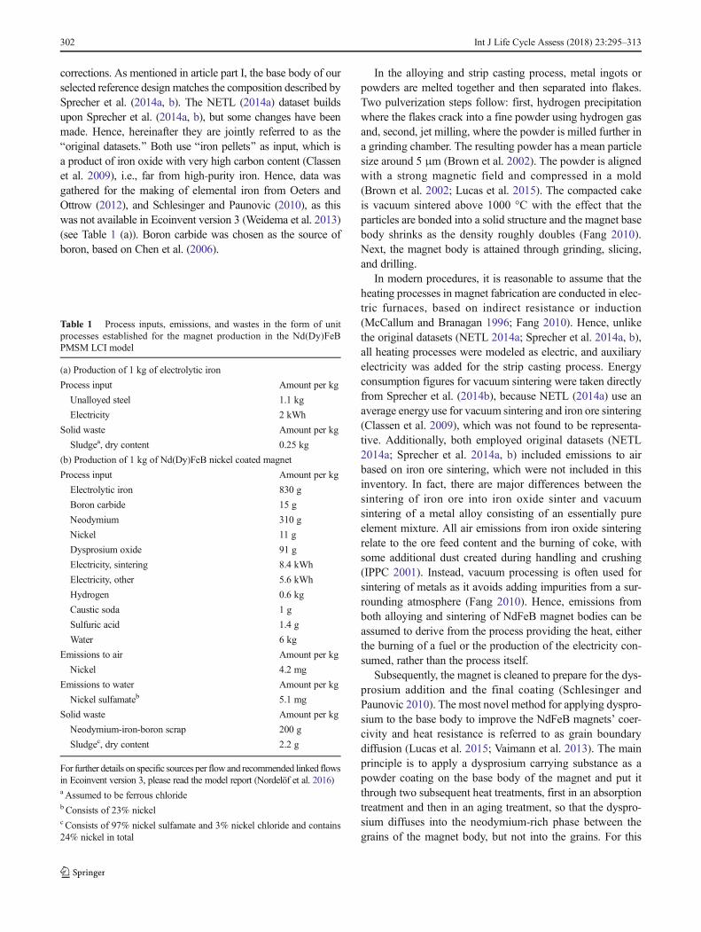
corrections. As mentioned in article part I, the base body of ourselected reference design matches the composition described bySprecher et al. (2014a, b). The NETL (2014a) dataset buildsupon Sprecher et al. (2014a, b), but some changes have beenmade. Hence, hereinafter they are jointly referred to as theBoriginal datasets.^ Both use Biron pellets^ as input, which isa product of iron oxide with very high carbon content (Classenet al. 2009), i.e., far from high-purity iron. Hence, data wasgathered for the making of elemental iron from Oeters andOttrow (2012), and Schlesinger and Paunovic (2010), as thiswas not available in Ecoinvent version 3 (Weidema et al. 2013)(see Table 1 (a)). Boron carbide was chosen as the source ofboron, based on Chen et al. (2006).
In the alloying and strip casting process, metal ingots orpowders are melted together and then separated into flakes.Two pulverization steps follow: first, hydrogen precipitationwhere the flakes crack into a fine powder using hydrogen gasand, second, jet milling, where the powder is milled further ina grinding chamber. The resulting powder has a mean particlesize around 5 μm (Brown et al. 2002). The powder is alignedwith a strong magnetic field and compressed in a mold(Brown et al. 2002; Lucas et al. 2015). The compacted cakeis vacuum sintered above 1000 °C with the effect that theparticles are bonded into a solid structure and the magnet basebody shrinks as the density roughly doubles (Fang 2010).Next, the magnet body is attained through grinding, slicing,and drilling.
In modern procedures, it is reasonable to assume that theheating processes in magnet fabrication are conducted in elec-tric furnaces, based on indirect resistance or induction(McCallum and Branagan 1996; Fang 2010). Hence, unlikethe original datasets (NETL 2014a; Sprecher et al. 2014a, b),all heating processes were modeled as electric, and auxiliaryelectricity was added for the strip casting process. Energyconsumption figures for vacuum sintering were taken directlyfrom Sprecher et al. (2014b), because NETL (2014a) use anaverage energy use for vacuum sintering and iron ore sintering(Classen et al. 2009), which was not found to be representa-tive. Additionally, both employed original datasets (NETL2014a; Sprecher et al. 2014a, b) included emissions to airbased on iron ore sintering, which were not included in thisinventory. In fact, there are major differences between thesintering of iron ore into iron oxide sinter and vacuumsintering of a metal alloy consisting of an essentially pureelement mixture. All air emissions from iron oxide sinteringrelate to the ore feed content and the burning of coke, withsome additional dust created during handling and crushing(IPPC 2001). Instead, vacuum processing is often used forsintering of metals as it avoids adding impurities from a sur-rounding atmosphere (Fang 2010). Hence, emissions fromboth alloying and sintering of NdFeB magnet bodies can beassumed to derive from the process providing the heat, eitherthe burning of a fuel or the production of the electricity con-sumed, rather than the process itself.
Subsequently, the magnet is cleaned to prepare for the dys-prosium addition and the final coating (Schlesinger andPaunovic 2010). The most novel method for applying dyspro-sium to the base body to improve the NdFeB magnets’ coer-civity and heat resistance is referred to as grain boundarydiffusion (Lucas et al. 2015; Vaimann et al. 2013). The mainprinciple is to apply a dysprosium carrying substance as apowder coating on the base body of the magnet and put itthrough two subsequent heat treatments, first in an absorptiontreatment and then in an aging treatment, so that the dyspro-sium diffuses into the neodymium-rich phase between thegrains of the magnet body, but not into the grains. For this
Table 1 Process inputs, emissions, and wastes in the form of unitprocesses established for the magnet production in the Nd(Dy)FeBPMSM LCI model
(a) Production of 1 kg of electrolytic iron
Process input Amount per kg
Unalloyed steel 1.1 kg
Electricity 2 kWh
Solid waste Amount per kg
Sludgea, dry content 0.25 kg
(b) Production of 1 kg of Nd(Dy)FeB nickel coated magnet
Process input Amount per kg
Electrolytic iron 830 g
Boron carbide 15 g
Neodymium 310 g
Nickel 11 g
Dysprosium oxide 91 g
Electricity, sintering 8.4 kWh
Electricity, other 5.6 kWh
Hydrogen 0.6 kg
Caustic soda 1 g
Sulfuric acid 1.4 g
Water 6 kg
Emissions to air Amount per kg
Nickel 4.2 mg
Emissions to water Amount per kg
Nickel sulfamateb 5.1 mg
Solid waste Amount per kg
Neodymium-iron-boron scrap 200 g
Sludgec, dry content 2.2 g
For further details on specific sources per flow and recommended linked flowsin Ecoinvent version 3, please read the model report (Nordelöf et al. 2016)a Assumed to be ferrous chlorideb Consists of 23% nickelc Consists of 97% nickel sulfamate and 3% nickel chloride and contains24% nickel in total
302 Int J Life Cycle Assess (2018) 23:295–313

reason, the temperature is preferably kept close to but belowthe sintering temperature. This is also important in order not todeform the magnet body structurally or alter the achievedmagnetic alignment (Nagasaki and Shimao 2015). Anotherchallenge is to achieve a uniform coating coverage beforeheating, but this can be overcome by electrodepositing finedysprosium oxide powder on the magnet body (Nagasaki andShimao 2015).
The process description and data for the grain boundarydiffusion of dysprosium into the base magnet body wasgathered from Nagasaki and Shimao (2015) and Suppanet al. (2015). It was combined with a theoretical descriptionof electrodepositing described in Schlesinger and Paunovic(2010) to calculate the energy use directly from Faraday’slaw for electrolysis resulting in a 0.3 kWh/kg magnet of ordi-nary grid electricity. The energy used for jet milling of thedysprosium oxide to proper particle size was taken fromSprecher et al. (2014b). Dysprosium oxide is milled to a par-ticle size below 10 μm and then mixed with ethanol to form aslurry bath before it is deposited by means of electricity.
The final coating, added to protect against corrosion, is alsoapplied by electroplating the magnet body, this time in a nickelsulfamate bath. Electroplating data was gathered from Moinget al. (2009), with some simplifications. For example, all so-dium salts used for cleaning (sodium carbonate, trisodiumphosphate, sodium gluconate, and caustic soda) were proxiedas caustic soda, this being the largest constituent. Pure nickelis dissolved at the anode and plated onto the magnet, acting asthe cathode. Several rinsing steps lead to water emissions fromdrag-out losses, but there can also be some evaporation ofnickel to air (Moing et al. 2009). The nickel coating thicknesswas set to 15 μm corresponding to 1% of the total magnetmass. Faraday’s law for electrolysis (Schlesinger andPaunovic 2010) was used again to scale the electricity usedin line with the deposited mass.
Finally, all magnets must be magnetized, either before theyare sent-off to the motor factory (premagnetization) or afterthey have been mounted into the rotor (postmagnetization).The magnetization process itself is very quick. A strong
magnetic pulse of 6 T (4–8 T) is applied during less than amillisecond (Sprecher et al. 2014a; Lucas et al. 2015).
To summarize this section, Table 1 (b) shows the resultinginventory for the magnet fabrication.
4 Manufacture of metal subparts, plastics,and insulation
The inventory model includes the production of all subparts inthe scalable PMSM. This chapter describes the making of allother parts, in parallel with the magnets, in the steps beforethey arrive to the motor factory.
4.1 General processing of steel and copper
All making of steel parts entering the motor factory, except forthe final electrical steel sheet processing, was modeled withactivities which are available ready-made in the Ecoinvent 3database to account for metal working, forming, and coating(Steiner and Frischknecht 2007; Classen et al. 2009; Weidemaet al. 2013). These activities were included in the LCI modelwithin the extended system boundary, but outside the regularsystem boundary, as explained in Sect. 2.3. For example, hotrolling, which is an intermediate steel making process wherethe ingots, blocks, and beams from raw steel making are treat-ed to enhance durability, shock resistance, and tensile strength,was applied on all types of steel alloys.
In summary, several rolling and machining activities wereselected to roughly match the making of different steel parts,i.e., steel coils, bearings, plates, bolts, nuts, and washers, alongwith the rod for making the shaft at the motor factory. Figure 3shows an overview of the recommended Ecoinvent 3 produc-tion efforts for steel parts, which were listed in the LCI model.Additionally, plates, nuts, bolts, and washers are then galva-nized, as accounted for in a separate zinc coating activity.
Similarly, themaking of copper wire for the conductors andcopper lugs in the connectors of the terminal block also referto predefined production activities in Ecoinvent 3 (Weidema
Fig. 3 Production efforts for steel available in Ecoinvent 3 (Weidema et al. 2013), specified per kilogram of material being processed. The processeshave been included within the extended system boundary of the LCI model to account for general processing of steel parts
Int J Life Cycle Assess (2018) 23:295–313 303

et al. 2013). Copper wire drawing includes rolling, cutting,and repeated pulls though different drawing dies to reducethe cross section to the desired size (Classen et al. 2009).Cable lugs are made by cutting and forging copper tubes, inturn made by rolling and drawing. Lugs are tin coated. Thecomplete production was modeled by combining rolling andmachining activities, and adding a tin plating process.
4.2 Electrical steel making
The starting point for making electrical steel is high-qualityhot rolled coils of silicon steel, as described in Sect. 4.1.However, prior to hot rolling, crude steel is alloyed into siliconsteel, containing on average 2% silicon and 0.4% aluminum(Lindenmo 2015), during the ladle processing of liquid steel(Ghosh 2000). Hence, it was accounted for as an add-on pro-cess within the making of unalloyed steel, as available inEcoinvent 3 (Weidema et al. 2013). Suitable amounts of alu-minum wire or ingots and granulates of ferrosilicon are mixedinto the liquid steel, beyond the standard use of ferrosilicon fordeoxidation (Ghosh 2000; Lagneborg and Waltersson 2004).Typical ferrosilicon (with 75% silicon) is a major source ofheat in the mixture, since it reacts exothermically (AMGVanadium 2015), and this was assumed to cover for the melt-ing of both added constituents, without the need for a supplyof additional heat energy in the ongoing steel making process.Table 2 (a) summarizes the process inputs.
At the electrical steel plant, the incoming silicon steelcoils are pickled, cold rolled into the desired thickness,and annealed to receive the desired Bnon-oriented^magnet-ic properties. Also, sheets are commonly coated with someinsulation material. Primary data for this process flow,shown in Fig. 4, was gathered from Surahammars BrukAB (Lindenmo 2012, 2015). Electricity is required to drivethe rolling mill, but also ventilation, lighting, and generalmachinery. Annealing is executed in a propane fired fur-nace. Pickling requires sulfuric acid in a bath. After passingthe bath, sheets are rinsed with water. Quicklime is used toneutralize the rinsing water, remaining acid on the steelsurface and sometimes complete expended pickling baths(Lewis and Boynton 1999; The National Lime Association2015). The result is a sludge, which must be disposed of,usually to a landfill. However, the pickling bath may also beused further in other industrial processing, e.g., in makingprecipitation chemicals. In this case, it was assumed that thepickling bath is not neutralized to become sludge, in linewith procedures at Surahammars Bruk AB (Lindenmo2015). Instead, it was regarded as a by-product of no value,and all the environmental load has been allocated to theelectrical steel sheets, these being the main product.Table 2 (b) shows the resulting unit process inventory forthe electrical steel plant.
Table 2 Process inputs, emissions, and wastes in the form of unitprocesses established for the production of parts in the Nd(Dy)FeBPMSM LCI model
(a) Alloying of 1 t of silicon steel
Process input Amount per 1000 kg
Unalloyed steel 979 kg
Ferrosilicon 27 kg
Aluminum 4 kg
(b) Production of 1 t of electrical steel sheets
Process input Amount per 1000 kg
Silicon steel, hot rolled 1140 kg
Electricity 630 kWh
Propane/LPG 12 kg
Sulfuric acid 19 kg
Rolling/lubricating oil 0.4 kg
Quicklime powder 0.8 kg
Phenolic resin 1 kg
Emissions to air Amount per 1000 kg
Carbon dioxide 36 kg
Nitrogen oxides 0.1 kg
Sulfur oxides 60 mg
Solid waste Amount per 1000 kg
Steel scrap 114 kg
Sludgea, dry content 3.3 kg
(c) Die casting of 1 kg of aluminum
Process input Amount per kg
Aluminum 1.06 kg
Heat, from natural gas 10.8 MJ
Electricity 2.6 kWh
Lubricating oil 20 g
Emissions to airb Amount per kg
Aluminum 0.4 g
VOC 1 g
Solid waste Amount per kg
Waste aluminumc 60 g
(d) Enameling 1 kg of magnet wire
Process input Amount per kg
Copper wire, uncoated 0.96 kg
Liquid enamel, polyester share 43 g
Liquid enamel, xylene solvent share 23 g
Electricity 0.5 kWh
Emissions to air Amount per kg
Xylene 23 g
For further details on specific sources per flow and recommended linkedflows in Ecoinvent version 3, please read the model report (Nordelöf et al.2016)a Consists of 60% calcium sulfate (CaSO4) and 40% ferrous hydroxide(Fe(OH)2)b Emissions from the burning of natural gas has not been included andmust be accounted for separatelyc Not recovered for recycling, but instead removed in mixture with otherfine scrap and dirt during cleaning
304 Int J Life Cycle Assess (2018) 23:295–313

4.3 Aluminum die casting
Casting is a common method for producing aluminumshapes such as cylindrical housings and endbells (Tong2014). Complex shapes can be produced with high ef-ficiency and at low cost, especially in large series pro-duction. Molten metal is poured or pressed into a die.Commonly, the term Bdie casting^ refers to the use of apermanent steel mold, i.e., a reusable die which can lastup to a million castings (Dalquist and Gutowski 2004).Data for a unit process was compiled from Roberts(2003), Dalquist and Gutowski (2004), and Heinemann(2016) (see Table 2 (c)). The making of the mold wasnot included, since it was assumed to have a negligiblecontribution per part in large-scale production.
Major steps in the die casting process are die preparation,metal preparation, casting, and finishing. The metal melting isconducted using a small natural gas furnace, whereas otherprocesses use electricity (Heinemann 2016). Direct emissionsmainly derive from the burning of natural gas (not included inTable 2 (c), but both preparation and casting also releasefumes of aluminum, as well as VOC emissions from oil-based lubricants (Dalquist and Gutowski 2004). Metal scrapand dross are to a large extent recovered and remelted withinthe facility. However, some dross and filings go to waste asunrecovered dirt (Heinemann 2016).
4.4 Preparation of parts with coatings, plastics, and otherinsulation materials
The difference between pure copper wire and magnet wire,i.e., the conductors in the stator windings (described in articlepart I), is the enamel coating layer. A liquid enamel film isapplied when copper wire is pulled through a nozzle in adedicated enameling machine (Brenn et al. 2012). Next, thecoated wire is dried and cured in an electric oven where sol-vents evaporate while chemical reactions inside the film leadto cross-linking of the enamel polymers (Czaputa 2012).Almost half of the heat necessary is released from the exother-mic curing reaction (Czaputa 2012). Electricity consumptiondata for enameling was gathered from MAG (2016) and thecomposition of the liquid enamel from Polynt Composites(2015). Results are shown in Table 2 (d).
Two subparts in the machine design contain polybutyleneterephthalate (PBT) plastics, the resolver, and the terminalblock. In both cases, injection molding is a common methodused to fabricate various shapes from plastic granulates.Extrusion is another, even more common way to make plastics(Hischier 2007). For the electric motor, this method is used forthe production of the polyethylene terephthalate (PET) slotliners and separators, as well as the soft cross-linked siliconerubber (elastomer) insulation for the phase conductors.Injection molding and extrusion of plastic and elastomer partswere accounted for within the extended system boundaries ofthe model, in the form of Ecoinvent 3 production activities(Weidema et al. 2013). Similar to the material conversion pro-cesses for metals, these activities can be viewed upon asreshaping services with a reference unit of 1 kg. However,unlike plastics, where most energy use during extrusion iscoupled to the heat necessary to plasticize granulates, siliconeis extruded at low temperature (Hischier 2007; Leoni 2014). Onthe other hand, heat is required for the silicone cross-linkingprocess (Leoni 2014). Hence, the selected Ecoinvent 3 activitywas still found to be a relevant approximation.
With the exception of PBT, the resolver is built with handwound magnet wire and electrical steel. Electrical steel losseswere accounted for, but energy use for punching was found tobe negligible. The machine design also contains syntheticproducts, such as the stator impregnation resin, the magnetfixation adhesive, the nylon lacing cord, and the housing var-nish. For all these materials, it was assumed that no furtherprocessing is necessary other than what is included in therecommended linked flows of Ecoinvent 3 reference products(Weidema et al. 2013). However, in particular, the mica tapeused for the phase insulation of the stator windings requiresseveral additional fabrication steps, compared to its input ma-terial composition. Still, for simplicity, and given the very lowcontribution to the overall machine mass, the processing of themica tape beyond the material constituents was investigatedbut neglected in terms of data inclusion.
Fig. 4 Electrical steel plant process flowchart
Int J Life Cycle Assess (2018) 23:295–313 305

5 The motor factory
5.1 Overview and building services
Figure 5 shows a process flow representative for a PMSMmotor factory. Overall, the flowchart was established basedon a site visit made to ELMO Malmköpings MekaniskaWerkstad AB in Sweden (Walter 2015), complemented by adescription of how to mount interior permanent magnets intothe rotor from Motorsolver LCC in Kentucky, USA(Hendershot 2015). Moreover, the steps for splining and sur-face hardening of the shaft were included based on the exper-tise of Låftman (2012). Encompassed processes have beennumbered in steps from 1 to 19 (see Fig. 5) to simplifyreferencing to specific processes in the following text. Notables with unit process data will be presented throughout thischapter, as it would be too detailed for the scope of the article.Neither will any aggregated gate-to-gate inventory be reportedfor the motor factory, since a key feature of the data gatheredhere is the matching with the scaling of the motor size, asdescribed in article part I. Instead, Sect. 5 provides a descrip-tion of the different processes and explains how varioussources were combined to establish this part of the LCI modelinventory.
In summary, in step 1, electrical steel sheets are turned intolaminations; in step 2, the stator core is built; in steps 3–5, thewinding is installed in the stator and secured with insulation;in step 6, the stator package goes through impregnation ofslots and end-windings; in step 7, conductors are furnishedwith connector lugs; in steps 8–10, a splined shaft is madefrom a uniform steel rod; in step 11, the rotor core is built inconjunction with the installation of segmented magnets; instep 12, the rotor end-plates are made from a sheet of stainlesssteel; in steps 13–14, the rotor package is brought into onepiece and balanced; in steps 15–17, die cast housing parts areprepared for assembly together with the terminal block; in step18, the machine is assembled with all subparts; and, in step 19,the exterior of the housing is painted before the motor is readyto leave the factory.
Additional to the specific manufacturing processes present-ed in Fig. 5 are several basic functions necessary to operate amotor factory, referred to as technical building services. Theserequire energy, and may cause emissions, relating to the totalactivity and size of the motor plant. Thus, the environmentalload carried by each electrical machine produced must bedecided by means of allocation. Typical building services in-clude heating or cooling, ventilation, lighting, and differenttypes of auxiliary energy use, e.g., electricity for compressedair and computers for various work and tasks.
An assessment of technical building services was conduct-ed for the ELMO plant and found to be fully based on elec-tricity (Walter 2016). Measurements from an energy audit(Karlsson 2013), and hourly power supply figures
representing 2013, were used as input (Walter 2016). Start-up and standby of machinery, as well as general use of com-pressed air for pneumatic control and blowing operations,were included. It was found that more than half the electricityused at ELMO during 2013 was coupled to building services,which is in line with other references (Gutowski et al. 2006;Bonvoisin et al. 2013). Furthermore, the ELMO plant pro-duces various metal components in addition to electrical ma-chine manufacturing. Seventy percent of the electricitycoupled to technical building services were allocated to elec-trical machine manufacturing, based on the general use ofcompressed air in relation to the two product types as beingthe best available indicator (Walter 2016). Another importantassumption was that the plant runs at current maximum ca-pacity, about five times higher than the actual production in2013, and that the overall time to produce one electrical ma-chine, gate-to-gate, is roughly the same regardless of machinetype, specific design, and size. The allocation was then basedon production time, and each PMSM unit was assigned thesame load for technical building services regardless of size,roughly 9 kWh of electricity per unit.
5.2 Producing the stator package
Electric machine manufacturing begins with the punching ofstator and rotor laminations from the same electrical steelsheet (process 1 in Fig. 5). The process is fast and efficientbut requires the making of an expensive stamping tool, de-signed to provide the desired geometry for the laminations.Next, in process 2, stator laminations are stacked, pressed, andjoined together on a fixture, often through welding (Walter2015). Rotor laminations continue on to process 11. Energyuse for punching was based on expert estimations for suitablesettings of the ELMO stamping equipment to make the smallreference machine laminations (Walter 2015). The same ener-gy use per kilogram of electrical steel was used for the largereference machine, matching a higher power load required fora larger cutting shape. Electricity and argon use for stackingand welding of the stator were gathered from Walter (2015).Scrap losses for processes 1 and 2were calculated bymeans ofgeometry and typical loss information.
Data for processes 3–5, i.e., installing the windings, includ-ing slot liners and separators, phase insulation and phase con-ductors, and the pressing of the end-turns, was gathered fromELMO (Walter 2015) and combined with lacing machine datafrom Ningbo Nide (2014). Slot liners are cut, shaped, andrapidly inserted into the stator by a machine. The same ma-chine is used to cut and shape separators, which are insertedlater. For the windings, magnet wire is wound into coils,which are mounted onto a fixture matching the number ofslots in the stator. The coils are then pulled through the statorinto the slots, inside the slot liners. In two-layer windings, thedeepest layer is pulled through first. Slot separators are placed
306 Int J Life Cycle Assess (2018) 23:295–313

Fig. 5 Motor factory process flowchart for a PMSM, divided into 19 processes
Int J Life Cycle Assess (2018) 23:295–313 307

in the slots and isolation tape is applied to the end-turns of theinstalled layer, by hand. Phase conductors are prepared bypinching or soldering ready-made insulated cables to the coilsor by threading tubes over the magnet wire conductors extend-ing from the coils. In order to secure the windings, end-turnsare laced with a thread and then machine pressed. Lacing andpressing account for most of the electricity used in processes3–5. It was assumed that there were no losses of phase con-ductor insulation and nylon thread.
Overall, the impregnation of the stator windings is oneof the most energy-demanding processes in the motor fac-tory (Karlsson 2013; Walter 2015) due to the need foroven heating. Several methods are possible, e.g., casting,dipping, and trickling (Richnow et al. 2014; Tong 2014).Trickling is an extensively used method, well suited forthe studied motor design. Resin is poured or sprayed ontothe winding in a fine jet, often when the stator is rotatingand slightly inclined, and then drawn into the cavities ofthe slots and end-windings by capillary action. Theamount of resin can be accurately managed without drip-ping losses and the processing time is relatively short,although the investment cost is high because advancedautomation equipment is required. Data for electricityuse of trickling was averaged out among nine machinesof two different types (Broomfield 2014a, b; NingboHaishu Nide 2014; Willard 2015). The length of zonesfor preheating, trickling, gelling, and curing were estimat-ed from machine drawings and combined with the heatingrequirements of the resin (Larrenduche 2015) to estimatethe cycle time. As an approximation, heating all zones upto their rated maximum temperature was set to require fullpower consumption of the machine, including auxiliariessuch as ventilation, and related linearly. Finally, 5% of theliquid epoxy resin base content were assumed to evapo-rate in the form of white smoke of hydrocarbons from thecuring process (Larrenduche 2015).
The loading capacity of the trickling machines was foundto relate primarily to the stator diameter yielding two fixedvalues for electricity use in impregnating the two referencemachines, 0.35 and 0.46 kWh. As a comparison, the dip andbatch bake procedure at ELMO, which is not dependent on thestator diameter in the same way, requires about 2 kWh perstator (Karlsson 2013; Walter 2015).
Before final assembly, in process 7 of Fig. 5, themain phase conductors, i.e., all wire branches joinedper phase, must be crimped with copper lugs to enableconnection to the terminal block (Walter 2015).Crimping is a form of resistance welding, where wireshave been stripped and placed compactly inside eachlug. The metal parts anneal and join strongly owing tohigh temperature. Energy use and copper scrap quantitywere calculated from information provided by AmadaMiyachi (2015), TES Vsetín (2015), and Walter (2015).
5.3 Building the rotor package
The making of the shaft in processes 8–10 of Fig. 5 is one ofthe three parallel subpart flows necessary to build the rotorpackage. Shaft machining procedures vary with the design,e.g., if hollow or solid and the type of mechanical joint.Nevertheless, the primary processing step comprises turningand forming the incoming steel rod into the desired shaft(Junker 2012). Other steps involve drilling and milling withhigh-precision computer control (Junker 2012). Splining is atypical example, where a cogwheel pattern is formed aroundthe shaft end to create the torque transmitting joint. All metalprocessing requires a continuous spray of Bcutting fluid^ forcooling and lubrication, this consisting mainly of naphtha di-luted in water (Statoil 2015a, b).
Data for steps 8 and 9 was collected from Walter (2015).However, although machinery representative for splining wasfound at ELMO, no ongoing activity could be used tomeasurethe splining cycle time. Instead, a simple feed rate estimate of1 m per minute at a tooth depth of 1 mmwas based on film clipobservations for milling in two rounds, one for roughing andone for finishing. It was assumed that doubling the tooth depthwould halve the feed rate and vice versa and that each centi-meter of diameter allowed for a set of 10 splines around thecircumference. All steel scrap losses were accounted for inprocess 8, by approximation.
Next, in step 9, the splined section of the shaft requiresinduction heat treatment to improve its mechanical properties(Tong 2014). The shaft’s surface temperature is rapidly raisedabove 1000 °C using an induced magnetic field for one or afew seconds only, followed by intensive quenching, usingwater mixed with an oil- or polymer-based quenching fluid(Rudnev et al. 2014; Tong 2014). The depth of heating re-quired is often only a few millimeters (Rudnev et al. 2014).Energy use data was collected from tabulated values inHaimbaugh (2001). Quenching time, flow, and fluid compo-sition were calculated from several sources (Poteet et al. 2006;Rudnev et al. 2014; Dow 2005a, b, 2014).
In the next activity, process 11 of Fig. 5, taking place inparallel with the preparation of the shaft, rotor core lamina-tions are stacked onto a fixture and magnet segments areplaced and fixated within the rotor slot cavities. Forpremagnetized magnets, automated equipment is difficult toacquire and the procedure used is generally manual (Frankeet al. 2011), although efforts have been made to develop newmounting machines (Franke et al. 2011; Franke et al. 2015;Hultman et al. 2014; Tremel et al. 2013). At the same time,large magnets are difficult to handle manually and these haveto be mounted in smaller sections. This coincides well withother benefits of segmentation, i.e., reduction of magnetlosses. A description of, and the data for, a hand mountingprocedure of magnets in IPM rotors was provided byHendershot (2015). Magnets are delivered in sections and
308 Int J Life Cycle Assess (2018) 23:295–313

rotor laminations are stacked with proper alignment on a fix-ture up to the same height as magnet length. North Pole mag-nets are then hand inserted in every other slot, followed by theSouth Pole magnets being fitted into the remaining slots. Thepolarity is inspected with a pole detector. The rotor segment isthen slightly heated with a hand held heat gun, before theadhesive is applied over each magnet and allowed to trickledown into the small cavities around the magnets. The heat gunis then applied again, from around 30 s up to a minute, to curethe adhesive. Lastly, the core segments with installed magnetsare stacked and aligned on a fixture or directly on the shaft.
Meanwhile, rotor endplates are fabricated, as in process 12in Fig. 5. Data was gathered fromWalter (2015). Endplates arepunched from a steel sheet in a stamping machine, similar tothe core laminations, but with lower energy use per kilogramof steel. A thick sheet requires a large punching force, butsince each plate is punched in one hit, the punch rate is muchlower. Parts are then integrated by threading the rotor coreonto the shaft and pressing in the endplates to hold everythingin place (see step 13 of Fig. 5). According to Walter (2015),the process entails a 20-t force being applied for 5 s. Powerconsumption information for such pressing was collectedfrom a hydraulic machine from Huahong Technology(2015). Total cycle time was assumed to be double the press-ing time, and any leakage of hydraulic oil was neglected.Lastly, the rotor is balanced by removing small amounts ofsteel from selected points of the endplate through the drillingof minor craters (see process 14 of Fig. 5). This involves twosteps, a balance test and drilling, which are repeated until asatisfactory rotor balance has been achieved. Data for thisprocedure was collected from Walter (2015).
5.4 Housing parts and final assembly
Die cast aluminum housing parts are machined at the motorfactory before they are ready for final assembly (see process15 of Fig. 5). Excessive material is removed from the work-piece, and holes or other types of fixation points are prepared.High precision is required for fitting, e.g., the housing bodywith the stator core and the endbells with the bearings. Thetolerance of bearing bores is around 1 μm (Walter 2015). Thisstep involves multiple operations, such as turning, cutting,drilling, milling, and threading. Aluminum scrap, mostlyshavings, but also dust, is generated, and machined parts haveto be blown clean by compressed air spray (see process 16 ofFig. 5).
Data for the preparation of the die cast aluminum parts wascollected from ELMO (Karlsson 2013; Walter 2015, 2016)and from Iro AB (Magnusson 2016), another electrical ma-chine manufacturer, in Sweden. Data was gathered in severalstages before being compiled: process time was assessedbased on the geometrics and surface areas of the parts; theamount of material removed and scrapped per part was
established from machining allowances and expert estima-tions; multi-operation electricity use was gathered from mea-surements; cutting fluid use was estimated from yearly con-sumption; and energy for cleaning was extracted from theoverall use of compressed air at the plant (Karlsson 2013;Appleton 2016; SWP 2016; Walter 2016).
Next, before the complete housing goes to final assembly,the terminal block is mounted onto the housing body. Thisoperation (number 17 in Fig. 5) was assumed to be manualand without losses. In the end assembly, process 18, the com-plete machine is put together in several steps. Most assemblyoperations are done by hand with support from automatedhandheld tools, apart from fitting the stator package into thehousing body and the bearings onto the shaft. Machine datawas gathered for a hydraulic press (Huahong Technology2015) for the stator fitting and a pneumatic press (driven bythe compressed air system of the plant) for the bearing fittingand combined with process settings stated by Walter (2016).
The connector lugs are coupled to the terminal block beforeall parts are merged into one unit by means of placing thebearings, now joined with the rotor package, into the boresof the endbells. The endbells are then secured to the housingand stator package using the dedicated fasteners. Alongside,the stator part of the resolver is connected to one of theendbells and the rotor part to the end of the shaft.Subsequently, the complete machine goes through a function-ality test sequence in a rig. Energy used by the test equipmentwas accounted for within technical building services.
Finally, in process 19 of Fig. 5, the housing surface isspray-painted with a transparent varnish and the machine setaside to cure at room temperature before delivery. Data for thisprocess was gathered from varnish and solvent suppliers(ExxonMobil 2007, 2014; Von Roll 2013; Larrenduche2015) and combined with the assessment of the compressedair system and standard spray gun properties (Meiji 2015).
6 Discussion and conclusions
New primary LCA inventory data for the manufacturing of anelectrical traction machine has been presented. Together withthe scalable design model for the motor mass and materialconfiguration, presented in part I of this article series, thisforms a comprehensive LCI model of a typical PMSM forautomotive electric driving applications.
The new production data includes a unit process for themaking of a Nd(Dy)FeB magnet, based on existing LCA datafor the NdFeB base body, which was updated and correctedafter detailed literature studies, and complemented with patentinformation for the addition of dysprosium. Furthermore, newLCA data has been presented for the alloy composition ofsilicon steel and the making of electrical steel based onSwedish steel mill data and expert interviews. Additionally,
Int J Life Cycle Assess (2018) 23:295–313 309

by combining data from various literature sources, new LCAunit process data have been established for the making ofelectrolytic iron, enameling of copper wire into magnet wire,and die casting of aluminum.
The most detailed survey of production was made for anelectric motor factory. Observations from the site visit toELMO’s Swedish motor factory were combined with detailedexpert interviews and included procedures at another Swedishplant and a manufacturing facility in Kentucky, USA. Furtherdetailswere providedmainly by specific plant data and suppliers’machine specifications. The end result is an extensive newdataset representing PMSM manufacturing in large volume.
Accordingly, the generation of the complete LCI model hasrequired a wide-ranging and comprehensive search for rawdata. This experience constitutes a good basis for a discussionon data collection methods. In the following, we discuss someof the observations and reflections made during the work.
Most apparent is that these new datasets provide examplesof different and complementing strategies to collect LCA data.The acquisition of data for electrical steel production repre-sents one type. This was straightforward and conventional.Although combined from several references, they all originatefrom the same organization and represent the same facility.However, companies may be unwilling to supply importantdetails, e.g., due to business secrecy. The most sensitive infor-mation needed to be obtained was the composition of thesilicon steel alloy, especially the specific compositions corre-sponding to certain grades of electrical steel. This issue wassolved by asking for the average composition of all siliconsteels used at the steel mill, which in this case was judged tobe equally valid and suitable for LCA. But, in other circum-stances, process details might be needed to make a productiondataset applicable and adjustable for altered product designs.Then, if it is not possible to acquire Bsingle-source^ data that isboth open and detailed, other methods must be sought.
To give one such example, the main method used for themotor factory was that of Bdata building,^ starting from a solidbase provided by the site visit and other facility records fromELMO. However, this factory produces electrical machines ofanother type, not PMSMs. As a consequence, while some partsof the surveyed process flowwere unrepresentative, others weremissing. In this mapping work, textbooks on manufacturingwere used as guides for further in-depth exploration ofsubject-specific technical publications. Interviews of expertswere also extensively used to provide overviews, for engineer-ing estimations, and to assess the representativity of the datacollected from technical documentation. A thorough under-standing of the product design was found to be important, asproduction routes are sometimes formed in close link to thedesign selections. For example, if the stator shall contain aprecise and deliberate amount of impregnation material, trick-ling of resin ismuchmore suitable than dipping thewhole statorinto varnish. The datasets for magnets, electrolytic iron,
310 Int J Life Cycle Assess (2018) 23:295–313
enameled wire, and die casted aluminum were generated in asimilar approach as in the motor factory, but from various liter-ature sources. The main benefit of the data building approach isthat the level of detail can be controlled to make the datasetflexible and relevant. In this project, it was necessary in order tomatch the scaling of the machine design with the motor factorymanufacturing model and correctly account for the function ineach production step. An important aspect was the possibility tokeep track of multiple output parameters when modeling theprocess outflows.
Finally, and most importantly, in order to make LCI datapossible to criticize, correct, and update, and thereby morebroadly applicable, it is essential to report transparent andpreferably detailed and disaggregated data records. This iscommendably well done in the previously publishedinventory data by Sprecher et al. (2014a, 2014b) and NETL(2014a), which made the correction and update of their datapossible. In contrast, the use of non-transparent and highlyaggregated information such as environmental productiondeclarations, which is not uncommon (Habermacher 2011;Weidema et al. 2013; Del Duce et al. 2016; Hernandez et al.2017), carries the risk of being misleading, since it is impos-sible to evaluate in terms of relevance.
7 Future research
The next step in this project will be to use the model in a fullLCA study and exemplify its applicability in the intendedcontext.
8 Accessing the LCI model file and model report
The life cycle inventory model file (Nordelöf 2016) and themodel report (Nordelöf et al. 2016) can be downloaded fromthe SPINE database provided by Swedish Life Cycle Center(http://cpmdatabase.cpm.chalmers.se/Scripts/sheet.asp?ActId=JT-2016-06-21-39).
Acknowledgements The authors would like to express their gratitudeto the Swedish Electromobility Centre and to the Area of AdvanceEnergy at Chalmers University of Technology for financing the project.We are also deeply grateful to all the data providers, especially ManuelWalter, CEO and owner of ELMO, Malmköpings Mekaniska WerkstadAB, Flen, Sweden.
Open Access This article is distributed under the terms of the CreativeCommons At t r ibut ion 4 .0 In te rna t ional License (h t tp : / /creativecommons.org/licenses/by/4.0/), which permits unrestricted use,distribution, and reproduction in any medium, provided you give appro-priate credit to the original author(s) and the source, provide a link to theCreative Commons license, and indicate if changes were made.
References
ABB (2002) Environmental Product Declaration: AC low voltage castiron motor, type M3BP 315. ABB Oy/BA Electrical Machines, LVMotors, Vaasa, Finland. (Document code: LV Motors/EPDM3BP315 GB 05–2002 3GZF500931–22)
Althaus H-J, Hischier R, Osses M, Primas A, Hellweg S, Jungbluth N,Chudacoff M (2007) Life cycle inventories of chemicals. 2007:Ecoinvent report no. 8. Swiss Centre for Life Cycle Inventories,Dübendorf (Data v2.0)
Amada Miyachi (2015) Hot crimping. Amada Miyachi Europe Gmbh,Puchheim, Germany (Technical specification for hot crimping/welding power supply. TDS RW M2-M4 Series RW 01-2015 EN)
Appleton (2016) Air tool or equipment CFM requirement. AppletonCompres so r Se rv i ce & Supp ly, Inc h t t p : / /web t e s t .appletoncompressor.com/wp-content/uploads/2011/04/Air-Tool-or-Equipment-CFM-Requirement.pdf. Accessed 2016-02-08
Arnell S (2012) Principal engineer, ABB Sustainability Reporting, ABBAB, Västerås, Sweden. Personal communication with Greger K.October 31:th, 2012.
Bonvoisin J, Thiede S, Brissaud D, Herrmann C (2013) An implementedframework to estimate manufacturing-related energy consumptionin product design. Int J Comput Integr Manuf 26(9):866–880
Brenn G, Steiner H, Baric E (2012) WIRE NEWS 12: high quality wirecoating in MAG magnet wire machines. MAG Maschinen- undApparatebau AG, Austria (Technical information brochure)
Broomfield (2014a) TM-25 trickle impregnation machine. BroomfieldLaboratories, United States of America (Machine specificationdatasheet for electric machine impregnation equipment)
Broomfield (2014b) TM-50 trickle impregnation machine. BroomfieldLaboratories, United States of America (Machine specificationdatasheet for electric machine impregnation equipment)
Brown D, Ma B-M, Chen Z (2002) Developments in the processing andproperties of NdFeb-type permanent magnets. J Magn Magn Mater248(3):432–440
Burress TA, Coomer CL, Campbell SL, Seiber LE,Marlino LD, StauntonRH, Cunningham JP (2008) Evaluation of the 2007 Toyota Camryhybrid Synergy drive system. Olszewski M. Electrical andElectronics Systems Research Division, Oak Ridge NationalLaboratory, US Department of Energy, USA
Burress TA, Coomer CL, Campbell SL, Wereszczak AA, CunninghamJP, Marlino LD, Seiber LE, Lin HT (2009) Evaluation of the 2008Lexus LS 600H hybrid Synergy drive system. Olszewski M.Electrical and Electronics Systems Research Division, Oak RidgeNational Laboratory. US Department of Energy, USA
Burress TA, Campbell SL, Coomer CL, Ayers CW, Wereszczak AA,Cunningham JP, Marlino LD, Seiber LE, Lin HT (2011)Evaluation of the 2010 Toyota Prius hybrid Synergy drive system.Olszewski M. Electrical and Electronics Systems ResearchDivision, Oak Ridge National Laboratory. US Department ofEnergy, USA
Chen SL, Liu W, Geng DY, Zhao XG, Zhang ZD (2006) Decompositionof B4C and magnetic properties of Nd–Fe–(B,C) alloys synthesizedby mechanical alloying. J Alloy Compd 415(1–2):271–275
Classen M, Althaus H-J, Blaser S, Scharnhorst W, Tuchschmid M,Jungbluth N, Emmenegger MF (2009) Life cycle inventories ofmetals. March, 2009: Ecoinvent report No. 10. Swiss Centre forLife Cycle Inventories, Dübendorf, Switzerland. (Data v2.1)
Croat JJ (1992) High energy product rare earth magnet alloys. UnitedStates of America Patent
Czaputa K (2012) WIRE NEWS 12: the serious idea behind the incred-ible Mozart zero. MAG Maschinen- und Apparatebau AG, Austria(Technical information brochure)
Dalquist S, Gutowski T (2004) Life cycle analysis of conventionalmanufacturing techniques: die casting. December, 2004: LMP-
MIT-TGG-03-12-09-2004. In: Environmentally benign manufactur-ing group, Laboratory for Manufacturing and Productivity.Massachusetts Institute of Technology, Boston http://web.mit.edu/ebm/www/publications
Del Duce A, Gauch M, Althaus H-J (2016) Electric passenger car trans-port and passenger car life cycle inventories in ecoinvent version 3.Int J Life Cycle Assess 21:1314–1326
Dow (2005a) Selection guide for UCON quenchants. The Dow ChemicalCompany, United States of America (Guide for the use of UCON™
quenchants during steel hardening. Form No. 118-01588-1005)Dow (2005b) UCON™ Quenchant RL. The Dow Chemical Company,
United States of America (Technical data sheet UCON™QuenchantRL. Form No. 118-01291-0205-rlr)
Dow (2014) Product safety assessment-UCON™ Quenchants and metal-working lubricants. The Dow Chemical Company, United States ofAmerica (Product safety description for UCON™ quenchants. FormNo. 233-000808-MM-0614X)
ExxonMobil (2007)Material safety data sheet: aromatic 100 fluid. ExxonMobil Corporation, United States of America (Product MSDS)
ExxonMobil (2014) Product safety summary: aromatic 100 fluid;Solvesso™ 100 fluid. Exxon Mobil Corporation, United States ofAmerica (Product safety datasheet)
Fang ZZ (ed) (2010) Sintering of advanced materials—fundamentals andprocesses. Woodhead Publishing Limited, Cambridge
Franke J, Tremel J, Kuhl A (2011) Innovative developments for automat-ed magnet handling and bonding of rare earth magnets. Paper pre-sented at the assembly and manufacturing (ISAM), 2011 I.E.International Symposium on, Tampere, Finland, 25–27 May.
Franke J, Hofmann B, Tremel J, Meyer A Innovative methods for auto-mated assembly and fixation of permanent magnets in electricalmachines. In: 12th Global Conference on SustainableManufacturing, Johor Bahru, Malaysia, 22–24 September, 20142015. pp 724–728. doi:10.1016/j.procir.2014.07.066
Ghosh A (2000) Secondary steelmaking: principles and applications.CRC Press, United States of America
Gutowski T, Dahmus J, Thiriez A (2006) Electrical energy requirementsfor manufacturing processes. Paper presented at the 13th CIRPInternational Conference of Life Cycle Engineering, Lueven,Belgium, May 31:st–June 2:nd
Habermacher F (2011) Modeling material inventories and environmentalimpacts of electric passenger cars. Master Thesis, Department ofEnvironmental Sciences, ETH Zurich, Switzerland
Haimbaugh RE (2001) Practical induction heat treating. ASMInternational, Materials Park, Ohio
Hawkins T, Gausen O, Strømman A (2012) Environmental impacts ofhybrid and electric vehicles—a review. Int J Life Cycle Assess17(8):997–1014
Heinemann T (2016) Energy and resource efficiency in aluminium diecasting. Sustainable production, life cycle engineering and manage-ment. Springer International Publishing, Switzerland
Hendershot JR (2015) President & CEO of Motorsolver LCC, SAE &ASME member, IEEE life fellow. Personal communication withNordelöf A. December 26:th, 2015
Hernandez M, Messagie M, Hegazy O, Marengo L, Winter O, Mierlo J(2015a) Electronic Supplementary Material—environmental impactof traction electric motors for electric vehicles applications. VrijeUniversiteit Brussel, Faculty of Engineering, Mobility andAutomotive Technology Research Group (MOBI), Brussels,Belgium (Supplementary Material for the International Journal ofLife Cycle Assessment)
Hernandez M, Messagie M, Hegazy O, Marengo L, Winter O, Mierlo J(2015b-2017) Environmental impact of traction electric motors forelectric vehicles applications. Int J Life Cycle Assess 22:55–65
Hischier R (2007) Life cycle inventories of packagings and graphicalpapers.—part II, plastics. 2007: Ecoinvent report no. 11. SwissCentre for Life Cycle Inventories, Dübendorf (Data v2.0)
Int J Life Cycle Assess (2018) 23:295–313 311

Huahong Technology (2015) Q43-1200A. Jiangsu Huahong TechnologyStock Co., Ltd. http://www.asiabaler.com/Q43.php. Accessed2016–02-05
Hultman E, Salar D, Leijon M (2014) Robotized surface mounting ofpermanent magnets. Mach Des 2(4):219
IPPC (2001) Integrated Pollution Prevention and Control (IPPC)—bestavailable techniques reference document on the production of ironand steel. December, 2001. European Commission
Johansson J (2015) Technical Specialist Power Electronics, Volvo GroupTrucks Technology, Volvo Group. Personal communication withNordelöfa. April 9:th, 2015
Junker S Highly flexible and efficient shaft manufacture for customizedelectric machines. In: Electric Drives Production Conference(EDPC), 2012 2nd International, 15–18 Oct. 2012 2012. pp 1–4.doi:10.1109/EDPC.2012.6425094
Karlsson P (2013) Mätning vid Malmköpings Mekaniska Werkstad AB.Industriell Laststyrning. (Measurement charts for energy and powerconsumption as part of an energy survey at MalmköpingsMekaniska Werkstad AB)
Koltun P, Tharumarajah A (2014) Life cycle impact of rare earth ele-ments. ISRN Metall 2014:10. doi:10.1155/2014/907536
Låftman L (2012) Senior technical specialist of electric motors, DanaherMotion Stockholm AB/Kollmorgen Corporation; DanaherCorporation. Personal communication with Greger K. November11:th, 2012.
Lagneborg R, Waltersson E (2004) Guide för legeringsmetaller ochspårelement i stål, 2nd edn. Jernkontoret, Stockholm
Lahd Geagea M, Stille P, Gauthier-Lafaye F, Millet M (2008) Tracing ofindustrial aerosol sources in an urban environment using Pb, Sr, andNd isotopes. Environ Sci Technol 42(3):692–698
Larrenduche D (2015) Global Product Line Manager, Vice PresidentProduct Line Management, Von Roll Isola France SA. Personalcommunication with Nordelöf A. September 5:th and 7:th, andOctober 28:th, 2015.
Leoni (2014) LEONI automotive cables. Leoni Kabel GmbH, Germany(Product catalogue for automotive cables)
Lewis CJ, Boynton RS (1999) Acid neutrilization with lime for environ-mental control and manufacturing processes. The National LimeAssociation, United States of America
LiWF, Sepehri-Amin H, Ohkubo T, Hase N, Hono K (2011) Distributionof Dy in high-coercivity (Nd,Dy)–Fe–B sintered magnet. ActaMater 59(8):3061–3069
Lindenmo M (2012) Manager development and technical customer sup-port, Cogent Power/Surahammars Bruk AB. Personal communica-tion with Greger K. December 4:th, 2012
Lindenmo M (2015) Manager Development and Technical CustomerSupport, Cogent Power/Surahammars Bruk AB. Personal commu-nication with Nordelöf A. June 21:st and 25:th, and August 21:st,2015
Liu NC, Stadelmaier HH (1986) High coercivity permanent magnet ma-terials based on iron-rare-earth-carbon alloys. Mater Lett 4(8–9):377–380
Lucas J, Lucas P, Le Mercier T, Rollat A, Davenport WGI (2015) Rareearths—science, technology. Production and Use Elsevier B.V,Amsterdam
MAG (2016) Mozart Zero H5—horizontal single line copper wire enam-elling machine. MAG Maschinen- und Apparatebau AG. http://www.mag.at/products/horizontal-machines/Mozart-H5.php.Accessed 2016-02-23
Magnusson P (2016) Product manager, mechanics, at IRO AB, van deWiele Group, Ulricehamn, Sweden. Personal communication withNordelöf a. February 9:th, 2016
McCallum RW, Branagan DJ (1996) Carbide/nitride grain refined rareearth-iron-boron permanent magnet and method of making. UnitedStates of America Patent
Meiji (2015) Spray gun painting equipment. Meiji Air Compressor MFGCO., LTD., Japan (Product catalogue for air spray painting equip-ment. Catalog number 151002KS)
Moing A, Vardelle A, Legoux JG, Themelis NJ (2009) LCA comparisonof electroplating and other thermal spray processes. In: Paper pre-sented at the thermal spray 2009: expanding thermal spray perfor-mance to new markets and applications. ASM International, LasVegas
Nagasaki Y, Shimao M (2015) Production method for rare earth perma-nent magnet. United States of America Patent
NETL (2014a) NETL life cycle inventory data–unit process: NdFeBpermanent magnet manufacturing [online]. Last updated: July 32014. Version 01. United Stated of America: U.S. Department ofEnergy, National Energy Technology Laboratory. Available: www.netl.doe.gov/LCA. Accessed October 29 2015 (Gate-to-gatemanufacturing process for 1kg plated NdFeB permanent magnet)
NETL (2014b) NETL life cycle inventory data–unit process: rare earthoxide electrolysis [online]. Last updated: June 5 2014. Version 01.United Stated of America: U.S. Department of Energy, NationalEnergy Technology Laboratory. Available: www.netl.doe.gov/LCA. AccessedOctober 29 2015 (Gate-to-gate process - electrolysisof a rare earth oxide using a fluoride-based process)
NETL (2015) NETL Unit Process Library. U.S. Department of Energy,National Energy Technology Laboratory. http://www.netl.doe.gov/research/energy-analysis/life-cycle-analysis/unit-process-library.Accessed October 29 2015
Ningbo Haishu Nide (2014) Varnish machine catalogue. Ningbo HaishuNide International Co., Ltd., China (Product catalogue for electricmachine impregnation equipment)
Ningbo Nide (2014) Induction machine catalogue. Ningbo NideMechanical Equipment Co., Ltd., China (Product catalogue for elec-tric machine manufacturing equipment)
Nordelöf A (2016) Scalable IPMSM LCI Model.xlsm [online]. Version1.0. Gothenburg, Sweden: Environmental Systems Analysis;Chalmers University of Technology. Distributed by The SwedishLife Cycle Center. Available: http://cpmdatabase.cpm.chalmers.se/Scripts/sheet.asp?ActId=JT-2016-06-21-39 (Gate to gate life cycleinventory in Microsoft Excel Macro-Enabled Worksheet)
Nordelöf A, Messagie M, Tillman A-M, Ljunggren Söderman M, VanMierlo J (2014) Environmental impacts of hybrid, plug-in hybrid,and battery electric vehicles—what can we learn from life cycleassessment? Int J Life Cycle Assess 19(11):1866–1890
Nordelöf A, Grunditz E, Tillman A-M, Thiringer T, Alatalo M (2016) Ascalable life cycle inventory of an electrical automotive tractionmachine—technical and methodological description, version1.0.2016: report no. 2016:4. Department of Energy andEnvironment, Divisions of Environmental Systems Analysis &Electric Power Engineering, Chalmers University of Technology,Gothenburg
Nuss P, Eckelman MJ (2014) Life cycle assessment of metals: a scientificsynthesis. PLoS One 9(7):12
Oeters F, Ottrow M (2012) Production of pure and high purity iron.Ullmann’s encyclopedia of industrial chemistry, vol 20. Wiley-VCH Verlag GmbH & Co, Weinheim
Överstam U (2013) LCA Scientist, ABB AB Corporate Research, ABBAB, Västerås, Sweden. Personal communication with Greger K. andNordelöf A. February 20:th and March 7:th, 2013
Polynt Composites (2015) Polymac 220–1935. Polynt Composites USA,Inc, USA (Technical specification for thermosetting polyester resinintended for coil coating)
Poteet D, Totten GE, Canale LCF (2006) Basic principles of quenchsystem design for induction hardening. In: Herring D (ed) HeatTreating: proceedings of the 23rd heat Treating societyConference, David L. Lawrence convention Center, Pittsburgh,Pennsylvania, USA, September 25–28, 2005 2006. ASMInternational, Materials Park, OH
312 Int J Life Cycle Assess (2018) 23:295–313

Richnow J, Stenzel P, Renner A, Gerling D, Endisch C Influence ofdifferent impregnation methods and resins on thermal behaviorand lifetime of electrical stators. In: 4:th International ElectricDrives Production Conference (EDPC), 2014 Sept. 30–Oct. 12014 2014. pp 1–7. doi:10.1109/edpc.2014.6984406
Roberts MJ (2003) Modified life cycle inventory of aluminium die cast-ing. Deakin University, Victoria
Rudnev V, Fett GA, Griebel A, Tartaglia J (2014) Principles of inductionhardening and inspection. In: Rudnev V, Totten GE (eds) ASMhandbook, induction heating and heat treatment, vol 4C. ASMInternational, p 820
Schlesinger M, Paunovic M (eds) (2010) Modern electroplating, 5th edn.John Wiley & Sons, Ltd., Hoboken
Sprecher B, Xiao Y, Walton A, Speight J, Harris R, Kleijn R, Visser G,Kramer GJ (2014a) Life cycle inventory of the production of rareearths and the subsequent production of NdFeB rare earth perma-nent magnets. Environ Sci Technol 48(7):3951–3958
Sprecher B, Xiao Y, Walton A, Speight J, Harris R, Kleijn R, Visser G,Kramer GJ (2014b) Life cycle inventory of the production of rareearths and the subsequent production of NdFeB rare earth perma-nent magnets—supporting information. Institute of EnvironmentalSciences (CML), Leiden University, The Netherlands (SupportingInformation for Environmental Science & Technology)
Statoil (2015a) Produktdatablad Coolway HD 25. Statoil Fuel andLubricants Sweden AB, Sweden (Cutting fluid technicalspecification)
Statoil (2015b) Säkerhetsdatablad: COOLWAY HD 25. Statoil Fuel &Retail Lubricants Sweden AB, Sweden (Cutting fluid MSDS)
Steiner R, Frischknecht R (2007) Metals processing and compresses airsupply. 2007: Ecoinvent report no. 23. Swiss Centre for Life CycleInventories, Uster, Switzerland (Data v2.0)
Suppan G, Ruehrig M, Kanitz A, Gores HJ (2015) Electroplating dyspro-sium from IL-based solutions: a promising electrochemical step toproduce stronger high performance Nd(Dy)-Fe-B sintered magnets.J Electrochem Soc 162(8):D382–D388
SWP (2016) Air tool consumption guide. Specialised Welding ProductsLtd. http://www.specialisedwelding.co.uk/manuals/Air_Compressor_Manuals/Air%20Tool%20Consumption%20Guide.pdf. Accessed 2016-02-08
TES Vsetín (2015) Hot crimping. TES Vsetín s.r.o, Czech Republic(Technical catalogue for hot crimping system)
The National Lime Association (2015) Iron and steel. Creativo Inc. http://www.hitachi-chem.co.jp/english/products/eim/001.html. Accessed29 July 2015
Tong W (2014) Mechanical design of electric motors. CRC Press, Taylor& Francis Group, Boca Raton
Tremel J, Hofmann B, Risch F (2013) Handling and fixation of perma-nent magnets. Adv Mater Res 769:3–10
US EPA (2012) Rare earth elements: a review of production, processing,recycling, and associated environmental issues. December, 2012:EPA 600/R-12/572. The U.S. Environmental Protection Agency(EPA), Office of Research and Development, Cincinnati, OH
Vaimann T, Kallaste A, Kilk A, Belahcen A Magnetic properties of re-duced Dy NdFeB permanent magnets and their usage in electricalmachines. In: AFRICON, 2013, 9–12 Sept. 2013. pp 1–5. doi:10.1109/AFRCON.2013.6757787
Vanadium AMG (2015) Silicon. AMG Vanadium Inc. http://amg-v.com/siliconpage.html. Accessed 21 May 2015
Volvo (2015) Volvo Electric Concept Bus. Volvo Bus Corporation,Sweden (Product datasheet for Volvo's all electric concept bus,BED 00685.15.05 SE)
Von Roll (2013) Varnish-Damicoat® 2405–2 natural. Von Roll FranceSA, France (Product datasheet)
Walter M (2015) CEO and owner, ELMO, Malmköpings MekaniskaWerkstad AB, Flen, Sweden. Personal communication withNordelöf A. August 27:th, October 10:th and November 4:th, 2015.
Walter M (2016) CEO and owner, ELMO, Malmköpings MekaniskaWerkstad AB, Flen, Sweden. Personal communication withNordelöf A. January 29:th, and February 2:nd and 8:th, 2016
Weidema BP, Bauer C, Hischier R, Mutel C, Nemecek T, Reinhard J,Vadenbo CO, Wernet G (2013) The ecoinvent database: Overviewand methodology, Data quality guideline for the ecoinvent databaseversion 3. The Centre for Life Cycle Inventories. www.ecoinvent.org. 2014–2016
Willard S (2015) Sales Manager at Broomfield Laboratories. Personalcommunication with Nordelöf A. December 18:th, 2015
Xue A (2015) Marketing & Sales Manager at Ningbo Nide MechanicalEquipment Co., Ltd. Personal communication with Nordelöf A.December 17:th, 2015
Yan G, McGuiness PJ, Farr JPG, Harris IR (2010) Optimisation of theprocessing of Nd–Fe–B with dysprosium addition. J Alloy Compd491(1–2):L20–L24
Zakotnik M, Tudor CO (2015) Commercial-scale recycling of NdFeB-type magnets with grain boundarymodification yields products with‘designer properties’ that exceed those of starting materials. WasteManag 44:48–54
Int J Life Cycle Assess (2018) 23:295–313 313