Embed Size (px)
Citation preview
A Salt-Rejecting Floating Solar Still for Low-Cost
Desalination
Journal: Energy & Environmental Science
Manuscript ID EE-ART-01-2018-000220.R2
Article Type: Paper
Date Submitted by the Author: 10-Mar-2018
Complete List of Authors: Ni, George; Massachusetts Institute of Technology, Mechanical Engineering Zandavi, Seyed Hadi; Massachusetts Institute of Technology, Mechanical Engineering Javid, Seyyed Morteza; University of Toronto Boriskina, Svetlana V.; Massachusetts Institute of Technology Cooper, Thomas; Massachusetts Institute of Technology, Mechanical
Engineering Chen, Gang; MIT, Mechanical Engineering
Energy & Environmental Science
A Salt-Rejecting Floating Solar Still for Low-Cost Desalination
George Ni1,†, Seyed Hadi Zandavi1,†, Seyyed Morteza Javid2, Svetlana V. Boriskina1, Thomas
Cooper1, Gang Chen1,*
1Department of Mechanical Engineering, Massachusetts Institute of Technology, 77
Massachusetts Avenue, Cambridge, Massachusetts 02139, USA.
2Department of Mechanical and Industrial Engineering, University of Toronto, 5 King's College Road, Toronto, ON, M5S 3G8, Canada.
†These authors contributed equally to this work.
*e-mail: [email protected]
Abstract
Although desalination technologies have been widely adopted as a means to produce freshwater, many of them require large installations and access to advanced infrastructure. Recently, floating structures for solar evaporation have been proposed, employing the concept of interfacial solar heat localization as a high-efficiency approach to desalination. However, the challenge remains to prevent salt accumulation while simultaneously maintaining heat localization. This paper presents experimental demonstration of a salt-rejecting evaporation structure that can operate continuously under sunlight to generate clean vapor while floating in a saline body of water such as ocean. The evaporation structure is coupled with a low-cost polymer film condensation cover to produce freshwater at a rate of 2.5 L m-2 day-1, enough to satisfy individual drinking needs. The entire system’s material cost is $3 m-2 – over an order of magnitude lower than conventional solar stills, does not require energy infrastructure, and can provide cheap drinking water to water-stressed and disaster-stricken communities.
Introduction
Water is an increasingly scarce resource around the world, with current projections estimating a staggering 3.9 billion people living in water-stressed areas increasing by 2025.1 A quarter of the world’s population, 1.6 billion, lives under economic water scarcity,2 and are unable to afford commercialized desalination technologies available in wealthier countries. Commercial desalination, which extracts fresh water from saline waters, include membrane-based designs such as reverse osmosis (RO),3 and thermal-based designs like multi-stage flash (MSF)4. Despite the maturity of these technologies, they are still unfeasible in developing regions due to high energy consumption, and require advanced supporting infrastructure and large centralized installations, which introduce a high economic barrier-to-entry.5,6 Existing desalination technology is particularly unsuitable for economically challenged populations living in distributed small villages, or remote regions. In these situations, advanced desalination technologies like RO and MSF are often 10x as expensive due small economy-of-scale and scarcity of fuel sources. Rudimentary options such as the solar still7 are often competitive. Low-cost, small-scale desalination technologies that operate using freely available solar energy have the potential to improve water security for the economically water stressed.
Page 1 of 15 Energy & Environmental Science
Recently, high-efficiency solar evaporation was achieved using floating structures, which do not require high-cost permanent construction or land use, and can be deployed directly on water surfaces.8-14 To achieve high evaporation rates, these structures localize heat generation to the water-air interface to avoid heating an entire large volume of water (such as the ocean). Our group previously demonstrated a heat-localizing solar evaporation approach using a floating double-layer structure, composed of exfoliated graphite as a solar thermal absorber and a porous carbon foam as the thermally insulating layer. The double-layer structure achieved steam and vapor generation at efficiencies as high as 85% under low solar concentrations (≤10 kWm-2). The heat localization concept8,9 was subsequently extended to incorporate plasmonic materials for solar absorption,15-19 paper-based carbon black coatings for cheaper solar absorption,14,20 improved thermal insulation through controlled water delivery strategies, 11,14,21 as well as graphene oxide and other exotic materials as absorbers.13,22,23 Ni et al even demonstrated high temperature (100°C) steam generation under unconcentrated sunlight (1 kWm-2, or 1 sun) with a floating solar receiver made of inexpensive households materials such as bubble wrap and styrofoam.11
These floating solar evaporation structures can potentially improve existing solar still designs. A low-intensity desalination technology for low infrastructure and remote regions,7 conventional solar stills have typical performances of around 2-4 liters of water per square meter per day, or annually averaged solar efficiencies of ~20-40%. Despite being invented centuries ago, conventional single-basin solar stills have not been widely adopted due to their comparatively high unit cost of production ($15-150 per m3 water).24 This high cost comes from the usage of materials such as steel, concrete, and glass to construct the solar still, coupled with the relatively low water production. A rich history of improvements have only increased system complexity and water costs, including using porous sponge cubes,25 floating absorbers,26,27 isolated evaporation wicks,28-31 and separate condensation chambers.32-34 Most importantly, conventional solar stills have not been able to solve the problem of fouling (An extensive review on solar stills can be found in Ref 35). Additional key shortcomings include the need to heat an entire volume of water, regularly cleaning of accumulated contaminants, and the generous land area needed to collect adequate sunlight.
Despite the potential improvements from coupling solar evaporation structures with solar stills, several unresolved challenges remain. Among these challenges are: (i) avoiding salt accumulation in the structure under continuous operation, (ii) maintaining high evaporation rates while condensing vapor, (iii) maintaining high temperatures in real seawater conditions, (iv) and shrinking desalination costs of conventional solar stills. Salt build-up remains a significant and poorly studied challenge for floating solar evaporation structures that employ heat localization. Seawater contains 3-3.5 wt% total dissolved solids, including NaCl and CaCO3, which can clog structures after evaporation. Previous works used hydrophobic surfaces to prevent salt from adhering.36 However, the structure needed to be thin to avoid clogging, and thus sacrificed thermal insulation. This is fundamentally because thermal insulation separates the evaporation interface from the cold saline water underneath, where salt needs to be rejected. Inadequate rejection can lead to clogged structures, ultimately deteriorating structure optical and wicking properties. Furthermore, water collection and desalination performance reported for floating evaporation structures (~5%) are far below the reported evaporation performance (~90%).14,17 The addition of a vapor collection system stifles the vapor flow conditions from those of open evaporation, and can suppress the evaporation and water collection rates. In addition, real seawater conditions have convective cooling from waves and currents, and this effect has been
Page 2 of 15Energy & Environmental Science
poorly studied in the literature. Most prior solar evaporation experiments were performed in beakers with still water, which adds extraneous thermal insulation. Lastly, even if solar evaporation structures can improve solar still water production (2-3 x), at negligible cost, the conventional solar still itself must be made an order of magnitude cheaper in order to compete with commercial desalination approaches like RO and MSF. Significant challenges remain before solar evaporation structures can be utilized competitively for desalination.
Here, we present a new approach to address fundamental challenges of salt rejection in solar evaporation for desalination. We demonstrate a floating multi-layer solar evaporation structure that rejects excess salts while preserving heat localization. In particular, salt rejection experiments revealed a strong resistance to fouling from NaCl, the most prevalent salt in ocean water. This work has ultimately yielded a low-cost floating solar still, made from commercially available materials that is capable of producing drinkable water continuously in saline waters, without the need for periodic cleaning. The floating solar still can produce water at 2.5 L m-2 day-
1, or a daily-averaged solar-to-water efficiency of 22%, enough to satisfy daily individual drinking needs. In addition, the traditional glass and steel solar still was replaced with a fully polymeric lightweight design expected to have a materials cost of ~$3 m-2, and 10-100 times lower than current solar still systems. Water collection tests were conducted both in a controlled rooftop setup and in the ocean. A heat transfer model of the solar still was also developed to identify areas for improvement. We believe this improved floating solar still design, capable of simultaneously rejecting salt and localizing heat, has the potential to significantly expand access to affordable clean water for off-grid communities, thus addressing one of the most pressing challenges in the water-energy nexus.
Solar Evaporation Structure and Design
Page 3 of 15 Energy & Environmental Science
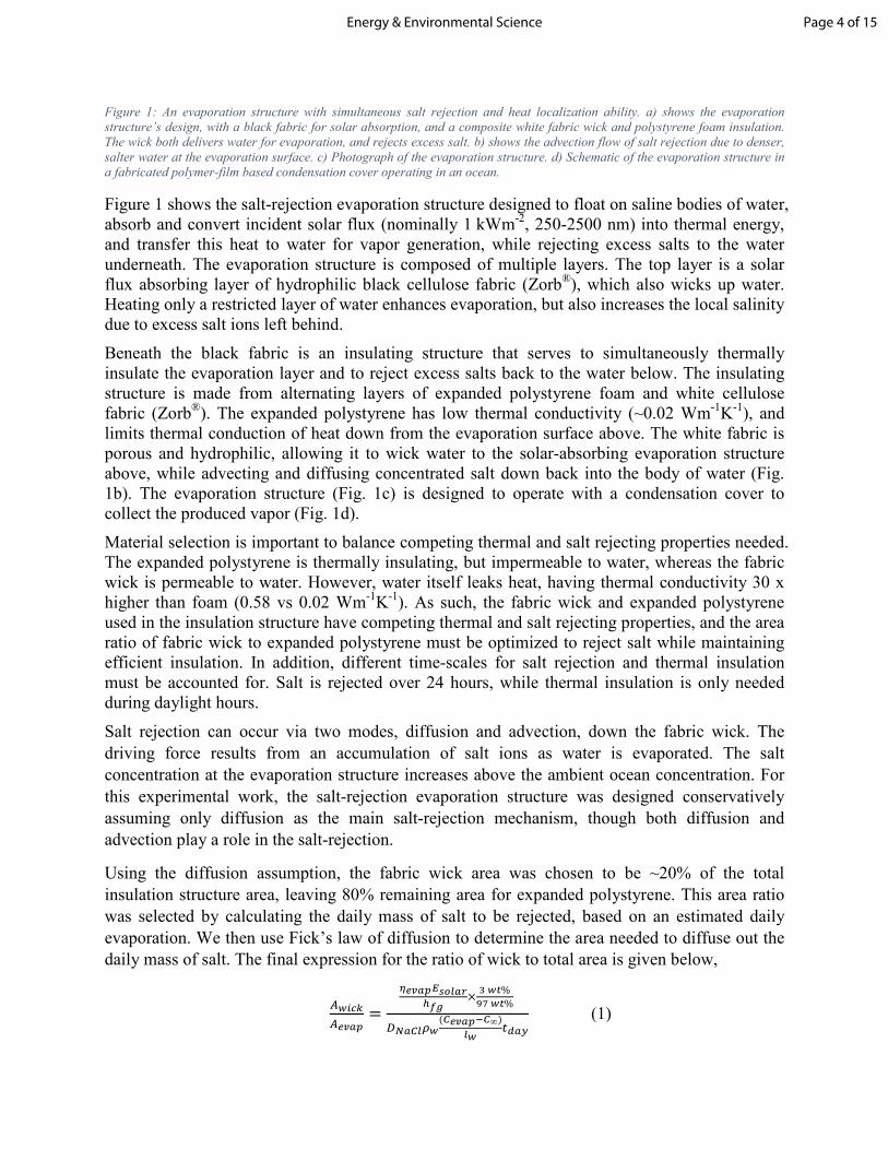
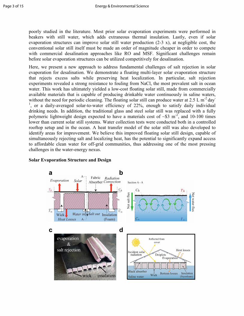
Figure 1: An evaporation structure with simultaneous salt rejection and heat localization ability. a) shows the evaporation
structure’s design, with a black fabric for solar absorption, and a composite white fabric wick and polystyrene foam insulation.
The wick both delivers water for evaporation, and rejects excess salt. b) shows the advection flow of salt rejection due to denser,
salter water at the evaporation surface. c) Photograph of the evaporation structure. d) Schematic of the evaporation structure in
a fabricated polymer-film based condensation cover operating in an ocean.
Figure 1 shows the salt-rejection evaporation structure designed to float on saline bodies of water, absorb and convert incident solar flux (nominally 1 kWm-2, 250-2500 nm) into thermal energy, and transfer this heat to water for vapor generation, while rejecting excess salts to the water underneath. The evaporation structure is composed of multiple layers. The top layer is a solar flux absorbing layer of hydrophilic black cellulose fabric (Zorb®), which also wicks up water. Heating only a restricted layer of water enhances evaporation, but also increases the local salinity due to excess salt ions left behind.
Beneath the black fabric is an insulating structure that serves to simultaneously thermally insulate the evaporation layer and to reject excess salts back to the water below. The insulating structure is made from alternating layers of expanded polystyrene foam and white cellulose fabric (Zorb®). The expanded polystyrene has low thermal conductivity (~0.02 Wm-1K-1), and limits thermal conduction of heat down from the evaporation surface above. The white fabric is porous and hydrophilic, allowing it to wick water to the solar-absorbing evaporation structure above, while advecting and diffusing concentrated salt down back into the body of water (Fig. 1b). The evaporation structure (Fig. 1c) is designed to operate with a condensation cover to collect the produced vapor (Fig. 1d).
Material selection is important to balance competing thermal and salt rejecting properties needed. The expanded polystyrene is thermally insulating, but impermeable to water, whereas the fabric wick is permeable to water. However, water itself leaks heat, having thermal conductivity 30 x higher than foam (0.58 vs 0.02 Wm-1K-1). As such, the fabric wick and expanded polystyrene used in the insulation structure have competing thermal and salt rejecting properties, and the area ratio of fabric wick to expanded polystyrene must be optimized to reject salt while maintaining efficient insulation. In addition, different time-scales for salt rejection and thermal insulation must be accounted for. Salt is rejected over 24 hours, while thermal insulation is only needed during daylight hours.
Salt rejection can occur via two modes, diffusion and advection, down the fabric wick. The
driving force results from an accumulation of salt ions as water is evaporated. The salt
concentration at the evaporation structure increases above the ambient ocean concentration. For
this experimental work, the salt-rejection evaporation structure was designed conservatively
assuming only diffusion as the main salt-rejection mechanism, though both diffusion and
advection play a role in the salt-rejection.
Using the diffusion assumption, the fabric wick area was chosen to be ~20% of the total
insulation structure area, leaving 80% remaining area for expanded polystyrene. This area ratio
was selected by calculating the daily mass of salt to be rejected, based on an estimated daily
evaporation. We then use Fick’s law of diffusion to determine the area needed to diffuse out the
daily mass of salt. The final expression for the ratio of wick to total area is given below,
���������
=
����� �������
���%����%
�������(���� �∞)
��"#�$
(1)
Page 4 of 15Energy & Environmental Science
where %&'() and %*+,- are the areas for salt rejection and evaporation, .*+,- is the estimated
daily evaporation efficiency, /012,3 is the total daily insolation, 45,62 is the mass diffusion
coefficient of NaCl in water, 7& is the partial density of water in seawater, 8& is the length of the
wick, 9:,; is the time length of one day, <*+,- and <∞ are the mass fraction of NaCl at the
evaporation surface and ocean. <*+,- is conservatively chosen to be the saturation condition for
NaCl (26 wt%), which minimizes the thermally detrimental wick area required. More details are given in the Supplementary Information.
Laboratory Experiments
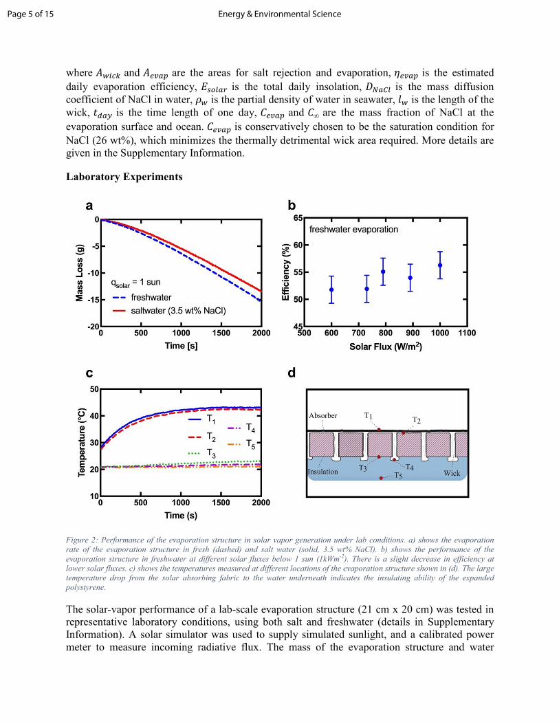
Figure 2: Performance of the evaporation structure in solar vapor generation under lab conditions. a) shows the evaporation
rate of the evaporation structure in fresh (dashed) and salt water (solid, 3.5 wt% NaCl). b) shows the performance of the
evaporation structure in freshwater at different solar fluxes below 1 sun (1kWm-2). There is a slight decrease in efficiency at
lower solar fluxes. c) shows the temperatures measured at different locations of the evaporation structure shown in (d). The large
temperature drop from the solar absorbing fabric to the water underneath indicates the insulating ability of the expanded
polystyrene.
The solar-vapor performance of a lab-scale evaporation structure (21 cm x 20 cm) was tested in representative laboratory conditions, using both salt and freshwater (details in Supplementary Information). A solar simulator was used to supply simulated sunlight, and a calibrated power meter to measure incoming radiative flux. The mass of the evaporation structure and water
Page 5 of 15 Energy & Environmental Science
reservoir was continuously monitored using a balance to determine the rate of vapor generation (Fig. 2a). The efficiency of solar-vapor conversion is defined as:
.*+,- ==> �?��
@ ��������, (2)
whereA> + is the mass flux at steady state conditions, ℎCD is the temperature-dependent latent heat
of vaporization of water, E012,3 is the incoming solar flux, and %*+,- is the area of the
evaporation structure exposed to the incoming solar flux. The sensible heat is neglected because cold water was not piped in to replace generated vapor. To isolate the effects of solar input, the evaporation rate in the dark was subtracted from the measured evaporation rate.
Floating in freshwater and under peak sunlight (1 kWm-2), the evaporation structure can generate vapor at 42°C and 57±2.5% efficiency. Importantly, when floating in simulated seawater (3.5 wt% NaCl), the evaporation structure generated vapor at comparable efficiencies (56±2.5%). To understand the evaporation structure performance under variable sunlight conditions, we further measured efficiency at solar intensities ranging from 600 Wm-2 to 1000 Wm-2 (Fig. 2b). Predictably, the evaporation efficiency reduces slightly (52±2.5% at 600 Wm-2) with lower sunlight, due to lower evaporation temperatures reached.
Our experiments revealed that the composite wicking-insulation structure succeeded in minimizing heat conduction downward from the liquid-air interface. Figure 2c shows the temperatures recorded at different locations (Fig. 2d) in the evaporation structure. After 4 hours of peak solar illumination (1 kWm-2), the water temperature underneath increased by only 4°C, due to reduced heat flux through the insulation structure. The heat conduction losses through the insulation structure are calculated to be 110 W m-2, corresponding to an 11% loss relative to the incoming solar energy. Radiative and convective losses from the top of the evaporation structure account for 11% and 9% of peak sunlight, respectively (see Supplementary Information). The remaining major losses are reflective optical losses of 15% from the wetted black fabric of the evaporation structure (measurement in Supplementary Information).
NaCl
NaCl rejected
simulated seawater
0:00 hr
0:15 hr
0:30 hr
0:45 hr
1:00 hr
1:15 hr
Salt Convection
ga
b
d
f
e
c
convection
Page 6 of 15Energy & Environmental Science
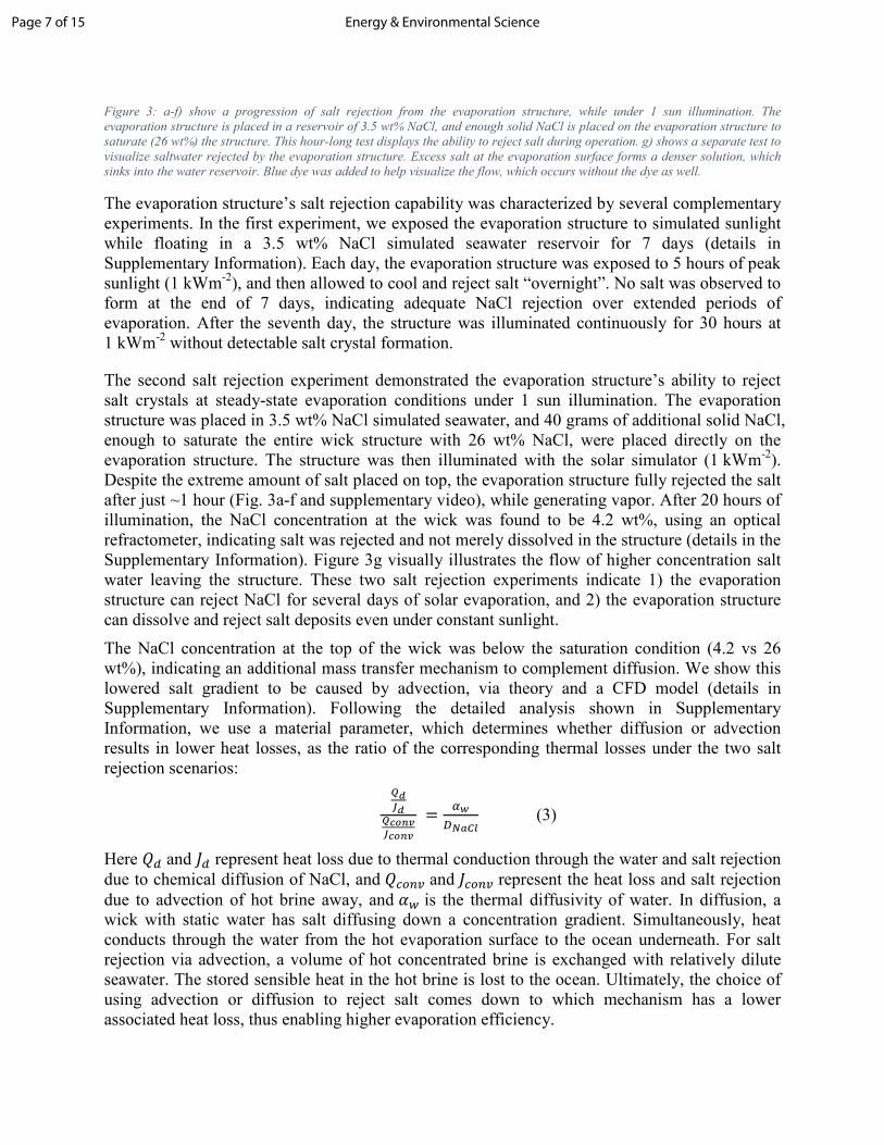
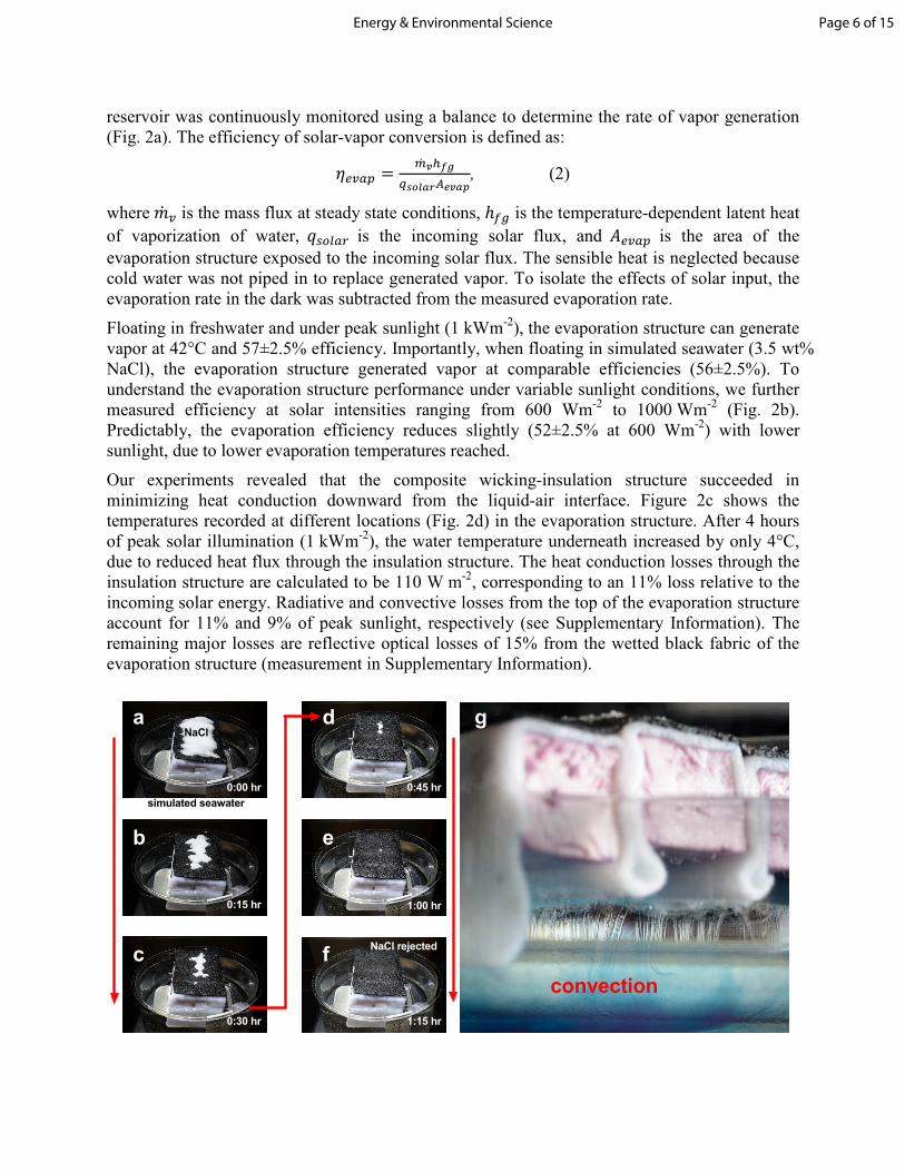
Figure 3: a-f) show a progression of salt rejection from the evaporation structure, while under 1 sun illumination. The
evaporation structure is placed in a reservoir of 3.5 wt% NaCl, and enough solid NaCl is placed on the evaporation structure to
saturate (26 wt%) the structure. This hour-long test displays the ability to reject salt during operation. g) shows a separate test to
visualize saltwater rejected by the evaporation structure. Excess salt at the evaporation surface forms a denser solution, which
sinks into the water reservoir. Blue dye was added to help visualize the flow, which occurs without the dye as well.
The evaporation structure’s salt rejection capability was characterized by several complementary experiments. In the first experiment, we exposed the evaporation structure to simulated sunlight while floating in a 3.5 wt% NaCl simulated seawater reservoir for 7 days (details in Supplementary Information). Each day, the evaporation structure was exposed to 5 hours of peak sunlight (1 kWm-2), and then allowed to cool and reject salt “overnight”. No salt was observed to form at the end of 7 days, indicating adequate NaCl rejection over extended periods of evaporation. After the seventh day, the structure was illuminated continuously for 30 hours at 1 kWm-2 without detectable salt crystal formation.
The second salt rejection experiment demonstrated the evaporation structure’s ability to reject salt crystals at steady-state evaporation conditions under 1 sun illumination. The evaporation structure was placed in 3.5 wt% NaCl simulated seawater, and 40 grams of additional solid NaCl, enough to saturate the entire wick structure with 26 wt% NaCl, were placed directly on the evaporation structure. The structure was then illuminated with the solar simulator (1 kWm-2). Despite the extreme amount of salt placed on top, the evaporation structure fully rejected the salt after just ~1 hour (Fig. 3a-f and supplementary video), while generating vapor. After 20 hours of illumination, the NaCl concentration at the wick was found to be 4.2 wt%, using an optical refractometer, indicating salt was rejected and not merely dissolved in the structure (details in the Supplementary Information). Figure 3g visually illustrates the flow of higher concentration salt water leaving the structure. These two salt rejection experiments indicate 1) the evaporation structure can reject NaCl for several days of solar evaporation, and 2) the evaporation structure can dissolve and reject salt deposits even under constant sunlight.
The NaCl concentration at the top of the wick was below the saturation condition (4.2 vs 26 wt%), indicating an additional mass transfer mechanism to complement diffusion. We show this lowered salt gradient to be caused by advection, via theory and a CFD model (details in Supplementary Information). Following the detailed analysis shown in Supplementary Information, we use a material parameter, which determines whether diffusion or advection results in lower heat losses, as the ratio of the corresponding thermal losses under the two salt rejection scenarios:
F#G#
F��H�G��H�
=I������
(3)
Here J: and K: represent heat loss due to thermal conduction through the water and salt rejection
due to chemical diffusion of NaCl, and J(1L+ and K(1L+ represent the heat loss and salt rejection
due to advection of hot brine away, and M& is the thermal diffusivity of water. In diffusion, a wick with static water has salt diffusing down a concentration gradient. Simultaneously, heat conducts through the water from the hot evaporation surface to the ocean underneath. For salt rejection via advection, a volume of hot concentrated brine is exchanged with relatively dilute seawater. The stored sensible heat in the hot brine is lost to the ocean. Ultimately, the choice of using advection or diffusion to reject salt comes down to which mechanism has a lower associated heat loss, thus enabling higher evaporation efficiency.
Page 7 of 15 Energy & Environmental Science
Subsequently, a numerical thermo-fluid simulation code was used to model the fluid flow, salt transport and temperature distribution in a single wick (Supplementary Information). The simulation results confirm that advection dominates the salt rejection process, and that there are counter-rotating two-dimensional advection currents in the salt rejecting wick (Fig. 1b).
Seawater contains many additional dissolved salts and ions beyond Na and Cl, such as Ca, K, Mg, Sr, which upon evaporation potentially form numerous sulfates and carbonates that can also clog the evaporation structure. Understanding that salt rejection occurs primarily through advection, the expected increase in concentration in these salts is expected to be similar to NaCl in the salt rejection expeirments (from 3.5 wt% to 4.2 wt%). We expect potential sulfates still to be rejected under continuous operation, and while carbonates have potential for build-up, they are at minute enough concentrations to possibly not affect the system. Details are in the Supplementary, Note S.8. Further study is needed to assess the impact of sulfates and carbonates on fouling, as well as biological fouling.
Condensation Structure
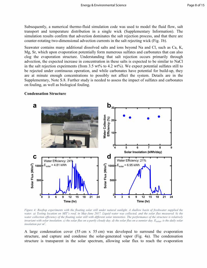
Figure 4: Rooftop experiments with the floating solar still under natural sunlight. A shallow basin of freshwater supplied the
water. a) Testing location on MIT’s roof, in May-June 2017. Liquid water was collected, and the solar flux measured. b) the
water collection efficiency of the floating solar still with different solar intensities. The performance of the structure is relatively
invariant with solar insolation. c) the solar flux on a partly cloudy day. d) the solar flux on a sunnier day. /012,3 is the daily solar
insolation per m2.
A large condensation cover (55 cm x 55 cm) was developed to surround the evaporation structure, and capture and condense the solar-generated vapor (Fig. 4a). The condensation structure is transparent in the solar spectrum, allowing solar flux to reach the evaporation
0 3 6 9 12 15 18 21 240
500
1000
Time (hr)
Solar Flux (W/m
2)
Water Efficiency: 24%
Esolar = 4.81 kWh
0 3 6 9 12 15 18 21 240
500
1000
Time (hr)
Solar Flux (W/m
2)
Water Efficiency: 21%
Esolar = 6.95 kWh
c d
a
4 5 6 7 8 90
10
20
30
Solar Insolation (kWh/day)
Water Collection
Efficiency (%)
b
Page 8 of 15Energy & Environmental Science
structure within. The condensed droplets on the cover coalesce and eventually drip into a catch tube. The water produced is typically very pure (~50 ppm).37 However, maximizing collection of all condensed droplets is a major challenge, as not all condensation surfaces are easily collectable.
The large condensation cover (55 cm x 55 cm) was tested in tandem with a large evaporation structure, forming the floating solar still. The floating solar still was deployed in a shallow basin filled with water on the roof of MIT, Cambridge, USA, and water collection was measured over several days during the summer. The condensate was collected in a nearby beaker. The instantaneous vapor temperature, incident sunlight, and ambient wind temperature and humidity were recorded. Here, the collection efficiency is defined as
.&,"*3 ==��H#?��
���� N@ ����("):", (4)
where .&,"*3 is the solar-water efficiency, A(1L: is the mass of condensate collected daily,
E012,3(9) is the time-dependent solar flux, and the denominator is the total daily solar insolation.
In this rooftop system, the maximum daily solar-water efficiency measured was 24%, while the maximum condensate collected was 2.81 L m-2 per day. Figure 4b shows similar performance between cloudy (Fig. 4c) and sunny days (Fig. 4d). The condensate produced from our 0.30 m2 still is 3.5 times higher compared to a previous work on floating solar stills14, and is adequate for daily individual drinking needs.
Ocean Testing
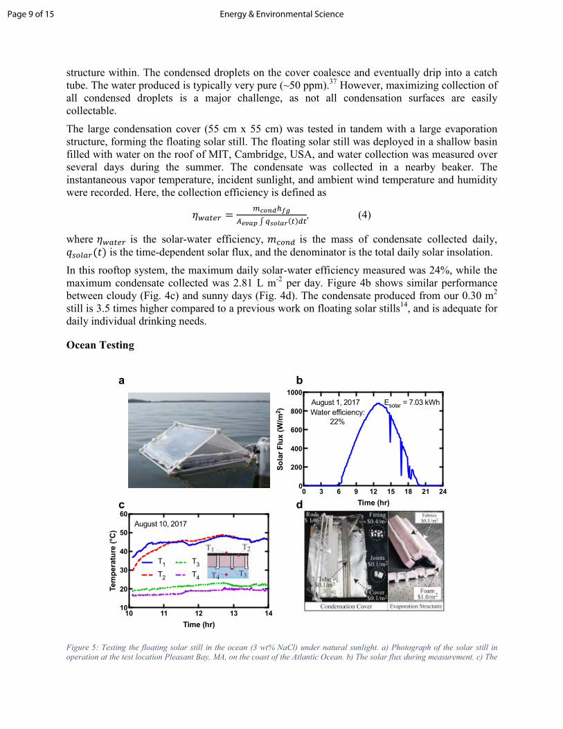
Figure 5: Testing the floating solar still in the ocean (3 wt% NaCl) under natural sunlight. a) Photograph of the solar still in
operation at the test location Pleasant Bay, MA, on the coast of the Atlantic Ocean. b) The solar flux during measurement. c) The
10 11 12 13 1410
20
30
40
50
60
Time (hr)
Temperature (°C
)
T1
T2
T3
T4
August 10, 2017
0 3 6 9 12 15 18 21 240
200
400
600
800
1000
Time (hr)
Solar Flux (W/m
2)
Water efficiency:
22%
August 1, 2017 Esolar = 7.03 kWh
a
dc
b
Page 9 of 15 Energy & Environmental Science
temperature evolution at different locations on the evaporation structure. d) The evaporation structure and condensation cover
breakdown of materials. The entire system can be assembled and disassembled by hand, and stored in a compact space.
We also tested the floating solar still in an ocean (Pleasure Bay, Boston, USA) to accurately assess the effect of ocean circulation on heat loss underneath the evaporation structure. The Pleasure Bay test location provides representative conditions of salinity (3 wt% NaCl), tides, and currents. The floating solar still was deployed on the bay from 10:30am to 3:00pm on August 1, 2017 (Fig. 5a), a representative sunny day (insolation shown in Fig. 5b). A total of 0.39 L of water was collected, corresponding to a solar-water efficiency of 22% during that time period (3.7 kWh m-2). For a sunny Boston summer day (7 kWh m-2 day-1), 2.5 L m-2 day-1 of water can be produced. However, the daily production depends on the total daily insolation, which varies dramatically (2-10 kWh m-2 day-1, or 0.7-3.6 L m-2 day-1) depending on weather, location, and season. Ideally, some kind of water storage can be incorporated for dispatchability. The ocean system’s production is slightly lower than the rooftop system due to additional convection heat losses under the solar still from ocean currents. A system heat transfer model of the entire solar still was developed to analyze sources of heat loss and areas for improvement (details in Supplementary Information).
Testing in the ocean displayed the floating solar still’s effectiveness in limiting heat conduction loss even with cold ocean water underneath. The temperatures of the evaporation structure floating in the ocean (on a different date) are shown in Fig. 5c. The temperature of the thermal insulation’s bottom surface is nearly constant as it exchanges heat with the bulk of the ocean water.
Discussion
We designed and experimentally demonstrated a new floating solar evaporation structure engineered to simultaneously reject salt while maintaining heat localization for enhanced evaporation. The salt rejection was proven in several lab and ocean experiments. Design guidelines are given to determine whether advection or diffusion should be used in salt rejection, and a thermofluid model was developed to guide future work. A collection cover was developed and paired with the evaporation structure, and freshwater was extracted from various saline waters. Lab-scale and ocean-scale testing was conducted to characterize the performance of the system, resulting in 22% solar-water performance. Coupled with the floating solar still’s low-cost design (~$3m-2), and an estimated life-cycle of 2 years, water production cost is $1.5 m-
3(breakdown in Figure 5d and Supplementary Information). This is 10 x lower than conventional solar stills (~$15 m-3). Though we only include the material cost here, the floating solar still is potentially cheaper than small-scale RO ($5-10 m-3), such as those used in the Maldives.38 State of the art large-scale RO desalination plants still produce fresh water at lower cost (~$0.5 m-3),6 but require high capital funding, access to the grid, and large production capacities.
There is still ample room for improvement of this technology. Higher collection efficiency can be reached by reducing the optical losses due to droplet formation on the cover. Substituting glass covers with polyester covers in our floating still has resulted in high optical loss (35%), due to the higher contact angle that water makes with hydrophobic polymers. This is in agreement with previous work that revealed that water collection efficiency of solar stills with the glass cover consistently exceeds that of identical stills with plastic covers by over 30%.39,40 Reduction of the optical transparency due to poor wettability of plastics has also been studied previously in simulations, which show droplet contact angle should be reduced below ~50° to reduce optical
Page 10 of 15Energy & Environmental Science
losses.41,42 One strategy may be using hydrophilic transparent polyesters, though the durability of this solution in water must be assessed. Another area for improvement is reduction of the wick area considering the prevalence of advective flow revealed in our study. The total wick area chosen in this study was based on the conservative assumption of diffusion-based salt rejection, and could be reduced to further minimize backside heat losses. The individual wick width is also important, as it affects the manufacturability (number of wicks needed), advection flow (due to viscous losses), and salt rejection (due to horizontal inter-wick salt flow at the evaporation surface). The wick width cannot be too narrow as to suppress advective flow, nor can it be too wide such that the inter-wick mass transport will dominate the salt rejection, rather than within the wick. There is an upper limit to how wide the wick can be, as it will increase the inter-wick spacing. At some point the inter-wick mass transport will dominate the salt rejection, rather than within the wick. Another area is reducing reflective losses at the fabric absorber (~15%, Supplementary Information). Other sources of loss include partial collection of all the condensate formed on the cover. In a traditional single-slope solar still, a glass cover tilted at 30° accounts for only 38% of the total condensable surface. In our floating solar still, we collect from 85% of the total condensable area, using a double-sloped design and wicks to collect from the sides. If all of these losses are addressed, our system model predicts 42% solar-water collection efficiency is achievable.
Experimental
The floating solar still was designed to be low cost and easily manufactured from widely available materials. The evaporation structure was constructed from cellulose-based fabric (Zorb®), and expanded polystyrene (Owen-Corning Foamular® 150). The condensation structure was constructed from lightweight and cheap polymer films. We evaluated several polymer films, eventually settling on commercial polyester films (McMaster-Carr #8567K32, 0.003” thick). The film was cut into several pieces, and welded together using a heat sealer (McMaster-Carr #2054T35). Droplet collection was facilitated using flaps of polyester film and fabric wicks (Zorb®), as an alternative to typical rubber drip edges and tubes. The polyester film was supported by plastic rods and joints. The wholesale materials cost of the entire floating solar still including evaporation structure and cover is ~ $3 m-2.
The evaporation structure was tested in the lab using a solar simulator (ScienceTech, SS-1.6K) outputting simulated solar flux between 600-1000 Wm-2 (1 sun). The solar flux was measured using a thermopile (Newport, 818P-040-55) connected to a power meter (Newport, 1918-C). Because the solar flux varies across the beam area, and the thermopile detector is smaller in area than the solar receiver, the solar flux was measured over 5 distributed locations and averaged. The evaporation structure was placed in a polycarbonate basin (21 cm x 22 cm x 3.5 cm), filled with fresh water or saline water. The mass loss of the water was measured using a balance with 0.1 g resolution (A&D, EJ3000). Steady-state evaporation rates were measured for 30 minutes once steady conditions were reached.
The temperatures were measured at five different locations of the evaporation structure shown in
Fig. 2d (OP : at the black absorber, OQ : wick below the absorber, OR : underneath the thermal
insulation,OS: in the wick bottom of the evaporation structure, and OT: in the bulk of the liquid) using thermocouples (Omega Engineering, 5TC-TT-K-40-36), and recorded using an Omega Engineering DAQPRO. The absorber temperature was measured by a thermocouple inserted into the evaporation fabric. Thermocouples were placed at the center, to represent the temperature of a sufficiently large absorber where side effects would be negligible. In Fig. 5c, only four
Page 11 of 15 Energy & Environmental Science
different temperatures are measured, with the bottom of the thermal insulation not measured. The
temperatures measured are: OP at the black absorber, OQ wick below the absorber,OR in the wick
bottom of the evaporation structure, and OS in the bulk of the liquid
For the day-to-day salt rejection experiments, water with 3.5 wt% NaCl was premixed and placed in the basin, which acted as a salt reservoir. For the week-long salt rejection experiment, the evaporation structure and salt reservoir were exposed to sunlight at 1 kWm-2 for 5 hours each day, then allowed to cool and reject salt for 19 hours. The mass of the entire system was monitored to determine the amount of water evaporated. Fresh water was added, as needed to the bottom of the salt reservoir at the beginning of experiment each day, to ensure the reservoir’s NaCl concentration remained constant at the start of each day. The evaporation structure surface was photographed daily to monitor the nucleation of NaCl crystals.
The saturation salt rejection experiments were conducted using a glass container with 2.9 L capacity (18 cm in diameter). Water with 3.5 wt% NaCl was premixed and placed in the glass container, which acted as a salt reservoir. A small (14 cm x 7 cm) evaporation structure was used. The small size was chosen to ensure the NaCl rejected to the reservoir wouldn’t significantly change the reservoir’s NaCl concentration. The area between the structure and the container was covered with a plastic cover. The entire setup was exposed to 1 kWm-2 of sunlight, and then 40 g of salt crystals were deposited on top of the evaporation structure. A camera periodically photographed the evaporation structure surface to show salt dissolving and rejecting over the course of a few hours. The salt concentration of the reservoir and evaporation structure top was measured using an optical refractometer with a resolution of 0.1 wt% NaCl (ATC SSA0010). A few drops (3 to 4) of liquid were sucked from the measurement location, and deposited onto the optical window of the refractometer. The final salt concentration in the salt water was 4.6 wt% after the salt rejection experiment.
Rooftop water collection measurements were performed with the large solar still (55 cm x 55 cm). The solar intensity (global horizontal irradiance) was measured using a Hukseflux LP-02 thermal pyranometer. The floating solar still was placed in a shallow basin of water (3 cm deep), placed on a table to avoid conductive heating from the rooftop surface. The floating solar still was oriented with the sloped panels facing south. Water collected from the still was routed via a tube to several sealed beakers. The beakers were emptied 2-3 times throughout the day, and the mass of water collected was recorded. The water collection was recorded through a 24-hour period, starting after sunset when the solar still had equilibrated to ambient temperature.
The ocean experiments were conducted in Pleasure Bay, located in South Boston, MA. The bay is connected to the Atlantic Ocean, and has a salinity of 3 wt%, as measured by the optical refractometer. The temperatures at different locations of the evaporation structure (shown in Fig. 5d of manuscript) and the ocean water were measured using thermocouples (Omega Engineering, 5TC-TT-K-40-36) and the Omega DAQPRO. The solar flux data was provided using a local weather station maintained by the MIT Sustainable Design Lab. The liquid water produced by the floating solar still was collected in submerged water bottles. The collected water was weighed at the end of the experiment to determine amount produced, and the salinity was measure to ensure that no seawater had leaked in.
Conclusions
A low-cost solar evaporation structure has been developed, which rejects excess salt while simultaneously maintaining heat localization for enhanced evaporation rates. Experiments were
Page 12 of 15Energy & Environmental Science
conducted to characterize the evaporation performance and salt rejection performances. A condensation system was developed to collect the generated vapors. The condensation system coupled with the evaporation structure formed a low-cost solar still, capable of seawater desalination at a rate of 2.5 L m-2 day-1, enough water for individuals to drink.
Floating deployment of our system directly on sea, ocean or lake surfaces helps to save agriculturally important land and natural ecosystems from being developed for energy and water production, and eliminates the need for water delivery infrastructure or manual labor. A small individual- or family-size floating still does not require larger community cooperation or external control over fair distribution of distilled water, making it a fast-to-deploy, simple-to-use, and conflict-free technology for disaster relief missions and sparsely-populated areas.
Acknowledgments:
We gratefully acknowledge funding support from the Abdul Latif Jameel World Water and Food
Security Lab (J-WAFS, a center created to coordinate and promote water and food research at
MIT under Agreement DTD 04/21/2015, for water desalination applications) and the support
from MIT S3TEC Center (an Energy Frontier Research Center funded by the Department of
Energy, Office of Science, Basic Energy Sciences under Award # DE-FG02-09ER46577 for
basic experimental infrastructure). S.H.Z. thanks Natural Sciences and Engineering Research
Council of Canada (NSERC) for their support. We thank William Wang for assistance in setting
up the ocean experiments.
Author contributions:
G.N., S.H.Z. and G.C. developed the concept. G.N. and S.H.Z conducted the experiments. G.N., S.M.J, S.H.Z, S.V.B and T.C. prepared the models. G.N., S.H.Z, S.V.B., T.C. and G.C. wrote the paper. G.C. directed the overall research.
Materials and Correspondence:
Please address all correspondences and materials requests to Professor Gang Chen ([email protected]).
References:
1. Hoffman, S. Planet water: Investing in the world’s most valuable resource. (John Wiley & Sons, 2009).
2. Molden, D. D., International Water Management Institute & Program, C. A. O. W. M. I. A. Water for food, water for life : a comprehensive assessment of water management in
agriculture. Choice Reviews Online 45, 45–0867–45–0867 (London ; Sterling, VA : Earthscan, 2007).
3. Malaeb, L. & Ayoub, G. M. Reverse osmosis technology for water treatment: state of the art review. Desalination 267, 1–8 (2011).
4. Khawaji, A. D., Kutubkhanah, I. K. & Wie, J.-M. Advances in seawater desalination technologies. Desalination 221, 47–69 (2008).
5. Energy, U. R. Water Desalination Using Renewable Energy. (IRENA, 2012).
Page 13 of 15 Energy & Environmental Science
6. Ghaffour, N., Missimer, T. M. & Amy, G. L. Technical review and evaluation of the economics of water desalination: current and future challenges for better water supply sustainability. Desalination 309, 197–207 (2013).
7. Kabeel, A. E. & El-Agouz, S. A. Review of researches and developments on solar stills. Desalination 276, 1–12 (2011).
8. Ghasemi, H. et al. Solar steam generation by heat localization. Nature Communications 5, 1–7 (2014).
9. Wang, Z. et al. Bio-inspired evaporation through plasmonic film of nanoparticles at the air-water interface. Small 10, 3234–3239 (2014).
10. Ito, Y. et al. Multifunctional porous graphene for high-efficiency steam generation by heat localization. Adv. Mater. 27, 4302–4307 (2015).
11. Ni, G. et al. Steam generation under one sun enabled by a floating structure with thermal concentration. Nat. Energy 1, 16126 (2016).
12. Zhou, L. et al. Self-assembly of highly efficient, broadband plasmonic absorbers for solar steam generation. Science Advances 2, e1501227–e1501227 (2016).
13. Yang, J. et al. Functionalized graphene enables highly efficient solar thermal steam generation. ACS Nano 11, 5510–5518 (2017).
14. Liu, Z. et al. Extremely cost-effective and efficient solar vapor generation under nonconcentrated illumination using thermally isolated black paper. Global Challenges 1, 1600003 (2017).
15. Tian, L. et al. Plasmonic biofoam: a versatile optically active material. Nano Letters 16, 609–616 (2016).
16. Zhao, D. et al. Enhancing localized evaporation through separated light absorbing centers and scattering centers. Sci. Rep. 1–10 (2015). doi:10.1038/srep17276
17. Zhou, L. et al. 3D self-assembly of aluminium nanoparticles for plasmon-enhanced solar desalination. Nature Photonics 1–7 (2016). doi:10.1038/nphoton.2016.75
18. Chang, C. et al. Efficient solar-thermal energy harvest driven by interfacial plasmonic heating-assisted evaporation. ACS Appl. Mater. Interfaces 8, 23412–23418 (2016).
19. Wang, X., He, Y., Liu, X., Cheng, G. & Zhu, J. Solar steam generation through bio-inspired interface heating of broadband-absorbing plasmonic membranes. Applied
Energy (2017). doi:10.1016/j.apenergy.2017.03.080 20. Liu, Y., Chen, J., Guo, D., Cao, M. & Jiang, L. Floatable, self-cleaning, and carbon-
black-based superhydrophobic gauze for the solar evaporation enhancement at the air–water interface. ACS Appl. Mater. Interfaces 7, 13645–13652 (2015).
21. Li, X. et al. Graphene oxide-based efficient and scalable solar desalination under one sun with a confined 2D water path. Proc. Natl. Acad. Sci. U. S. A. 113, 13953–13958 (2016).
22. Xu, N. et al. Mushrooms as Efficient Solar Steam-Generation Devices. Adv. Mater. 10, 1606762 (2017).
23. Hu, X. et al. Tailoring graphene oxide-based aerogels for efficient solar steam generation under one sun. Adv. Mater. 29, 1604031 (2016).
24. Kabeel, A. E., Hamed, A. M. & El-Agouz, S. A. Cost analysis of different solar still con. Energy 35, 2901–2908 (2010).
25. Abu-Hijleh, B. A. & Rababa’h, H. M. Experimental study of a solar still with sponge cubes in basin. Energy Convers. Manage. 44, 1411–1418 (2003).
Page 14 of 15Energy & Environmental Science
26. Nafey, A. S., Abdelkader, M., Abdelmotalip, A. & Mabrouk, A. A. Enhancement of solar still productivity using floating perforated black plate. Energy Convers. Manage. 43, 937–946 (2002).
27. Delano, W. Solar still with floating slab-supporting particulate radiant energy receptor. (1970).
28. Al-Karaghouli, A. A. & Minasian, A. N. A floating-wick type solar still. Renewable
Energy 1, 77–79 (1995). 29. Minasian, A. N. & Al-Karaghouli, A. A. An improved solar still: the wick-basin type.
Energy Convers. Manage. 36, 213–217 (1995). 30. Janarthanan, B., Chandrasekaran, J. & Kumar, S. Performance of floating cum tilted-
wick type solar still with the effect of water flowing over the glass cover. Desalination 190, 51–62 (2006).
31. Mahdi, J. T., Smith, B. E. & Sharif, A. O. An experimental wick-type solar still system: Design and construction. Desalination 267, 233–238 (2011).
32. Abu-Hijleh, B. A. Enhanced solar still performance using water film cooling of the glass cover. Desalination 107, 235–244 (2002).
33. El-Bahi, A. & Inan, D. Analysis of a parallel double glass solar still with separate condenser. Renewable Energy 17, 509–521 (1999).
34. Kumar, S. & Tiwari, G. N. Life cycle cost analysis of single slope hybrid (PV/T) active solar still. Applied Energy 86, 1995–2004 (2009).
35. Lienhard, J., Antar, M. A., Bilton, A. & Blanco, J. Solar desalination. Annual Review of
Heat Transfer 277–347 (2012). 36. Kashyap, V. et al. A flexible anti-clogging graphite film for scalable solar desalination
by heat localization. J. Mater. Chem. A 5, 15227–15234 (2017). 37. Van der Bruggen, B. & Vandecasteele, C. Distillation vs. membrane filtration: overview
of process evolutions in seawater desalination. in 143, 207–218 (2002). 38. Ibrahim, S. A., Bari, M. R., Sanitation, L. M. M. W. A.2002. Water resources
management in Maldives with an emphasis on desalination. academia.edu
39. Tleimat, B. W. & Howe, E. D. Comparison of plastic and glass condensing covers for
solar distillers. Solar Energy 12, 293–304 (1969). 40. Phadatare, M. K. & Verma, S. K. Effect of cover materials on heat and mass transfer
coefficients in a plastic solar still. Desalination and Water Treatment 2, 254–259 (2012). 41. Tow, E. W. The antireflective potential of dropwise condensation. J. Opt. Soc. Am. A 31,
493 (2014). 42. Zhu, K., Huang, Y., Pruvost, J., Legrand, J. & Pilon, L. Transmittance of transparent
windows with non-absorbing cap-shaped droplets condensed on their backside. Journal
of Quantitative Spectroscopy and Radiative Transfer 194, 98–107 (2017).
Page 15 of 15 Energy & Environmental Science