Embed Size (px)
Citation preview

CIRP Journal of Manufacturing Science and Technology 6 (2013) 22–33
A roughness model for the machining of biomedical ceramics bytoric grinding pins
Berend Denkena, Jens Kohler, Marijke van der Meer *
Institute of Production Engineering and Machine Tools, Leibniz Universitat Hannover, An der Universitat 2, 30823 Garbsen, Germany
A R T I C L E I N F O
Article history:
Available online 18 August 2012
Keywords:
Five-axis machining
Toric grinding pins
Biomedical ceramics
Modeling
Roughness prediction
A B S T R A C T
Applying bioceramics for complex-shaped endoprostheses promises to improve the implant durability
significantly. High precision grinding and polishing processes for free-formed ceramic surfaces are
therefore essential. The contact conditions for grinding with toric pins are focused to ensure a constant
material removal along the tool path. Based on the geometrical intersection, it is possible to calculate the
roughness. Furthermore, the grinding layer topography and the grinding kinematics are taken into
account to predict the resulting roughness, which is verified by grinding experiments. The wear of
machined ceramic pairings is therefore reduced by a factor of 30 compared to conventional cobalt-
chrome–polyethylene pairings.
� 2012 CIRP.
Contents lists available at SciVerse ScienceDirect
CIRP Journal of Manufacturing Science and Technology
jou r nal h o mep age: w ww.els evier . co m/lo c ate /c i rp j
1. Introduction
Every fourth German adult suffers from osteoarthrosis [1]. At anadvanced age, the natural cartilage wears out. The knee is affectedin most cases (Fig. 1) [2]. In the regions concerned, the joint can bereplaced by an endoprosthesis.
Consequently, 170,000 knee joints per year are medicallytreated with implants in Germany. The annual amount of revisionoperations is 9600 [3,4]. There are many reasons for post-treatments restoring the joint replacement by a new endoprosth-esis, e.g. due to an infection or breakage, but the main reason is theimplant loosening resulting from an agglomeration of polyethyl-ene wear particles [5–7]. Current activities focus on the enhance-ment of the wear resistance and the development of coatings withdiamond-like [8,9] and ceramic [10] substances. New materialssuch as Oxinium1 or CeraMetal1 have also been developed[11,13]. However, efforts of many years have particularly shownthat the application of composite ceramics is very promising[14,15]. All actions still have the weakest link – the polyethylenecomponent – in common.
Although low-wear hard–hard-pairings have been widely usedin the total hip arthroplasty for more than 30 years [16], kinematicsand complex geometries combined with high requirementsconcerning the implant quality have avoided the application ofall-ceramic implants in the total knee arthroplasty. ‘‘As (. . .) new
* Corresponding author. Tel.: +49 511 762 19074; fax: +49 511 762 5115.
E-mail addresses: [email protected], [email protected]
(M. van der Meer).
1755-5817/$ – see front matter � 2012 CIRP.
http://dx.doi.org/10.1016/j.cirpj.2012.07.002
production methods are being developed, we anticipate excellentacceptance and growth of the ceramic total knee replacementmarket.’’, said a technological market leader about the highdemand of new manufacturing processes [17]. In addition, themachining of complex ceramic implant surfaces would be theorigin of a notable increase in lifetime of several otherendoprostheses. This work is therefore focused on one of thedetermining process steps, the grinding process.
2. Modeling in grinding
Numerous approaches in modeling shall give a comprehensiverepresentation of the grinding process. According to Heinzel [18],the number of publications related to grinding technology focusingon modeling and simulation has increased by the factor of 5 from1970 to 2004. With finite-element methods, molecular-dynamicmodels of single grain engagements, process design models basedon synthetic neural networks, rule- and knowledge-based models,analytical models, as well as regression models it is possible todescribe the effects of thermal, chemical, dynamic and mechanicalprocesses. Especially kinematic–geometric models have a greatpotential to enhance a better understanding of the grindingprocess due to their simplified considerations.
2.1. Contact and engagement conditions
During five-axis manufacturing it is possible to incline the toolin relation to the machined surface via the additional tworotational axes besides the three translational axes [19]. In thisway, the five-axis grinding enables the development of new

Fig. 1. Gonarthrosis – wear of knee joint visible by the direct contact of bones.
B. Denkena et al. / CIRP Journal of Manufacturing Science and Technology 6 (2013) 22–33 23
application fields such as the production of complex tools, forgingdies, structured ceramics and turbine blades [20,21]. In thiscontext, different research works are introduced for the finishing offree-formed surfaces of dies and molds and optical componentsregarding belt grinding, the application of small grinding pins andcup grinding wheels, respectively [22–24].
Radius grinding wheels are applied in the multi-axismanufacturing and examined concerning contact and engagementconditions as well as form deviations [25,26]. The research isfocused on orthogonal manufacturing processes without toolinclination and rounded, discoid and spherical-shaped grindingwheels.
Further experiments in this context consider special kinematicswith complex contact and engagement conditions such as geargrinding [27], tool grinding [28], and riblet grinding on turbineblades [29] (Fig. 2).
Moreover, holistic approaches are adopted with an additionalinclusion of machine and workpiece. The interactions duringgrinding are then depicted [30].
2.2. Grinding tool characterization
The grinding wheel micro topography has an influence on themachining result. In order to carry out a significant process designconcerning generated surface properties, a three-dimensional
Fig. 2. Examples of complex contact a
detection and description of the abrasive layer is recommended.This requires a connection of characteristic topography parameterswith the expected grinding results [31,32].
The constantly changing abrasive layer topography must betaken into account due to wear [33]. Hou and Kommanduri [34]have investigated the statistical properties of the grinding processwith mathematical methods to define the number of active grains.Besides a better understanding of the grinding process, it ispossible to create a basis for thermal analyses and wearevaluations. Additionally the grinding wheel elasticity is decisivefor the surface generation, which is graphically presented by three-dimensional grain–workpiece interactions [35]. Besides thedescription of the grinding layers depending on tactile measure-ments, these are synthesized by statistical modeling methods[36,37] (Fig. 3, left).
Chen et al. [38] even modeled the dressing of a simulatedgrinding tool, which exhibits several grain layers with statisticallydistributed spherical grinding grains. The roughness generation isregarded, measured and simulated data combined, for differentprocess parameters using this tool for peripheral grinding. A greatinfluence of the grain distribution on the produced roughness wasdetected [39].
2.3. Roughness modelling
Kassen and co-workers [40–42] are pioneers in the kinematic–geometric modeling defining the roughness orthogonal to thegrinding direction with two-dimensional grain models for surfaceand cylindrical grinding. Koshy et al. [43] developed three-dimensional grinding layer models and compared real andsimulated workpiece roughness values for different materials.Thus, the surface roughness is extensively determined by the grainprotrusion.
Analog Chakrabarti [37] deduced roughness parameters fromthe overlapping paths of the interpenetration of truncated pyramidgrain models with the workpiece (Fig. 3, right). The middle profileline corresponds to the average of all height values Y for all datapoints orthogonal to the grinding direction X.
Agarwal and co-workers [44,45] reached a good balancebetween theory and practice during the examination of aroughness model based on analytical chip thickness determinationfor different grain groove geometries. Salisbury et al. [46] is
reas during multi-axis grinding.

Fig. 3. Synthetic grinding layer topography and simulated roughness [37].
B. Denkena et al. / CIRP Journal of Manufacturing Science and Technology 6 (2013) 22–3324
concerned with a three-dimensional surface model, whichincludes a grinding wheel model. By means of iteration with backfeeded simulated surface also leveling effects can be reproduced.
There are currently different modeling methods and manifoldcombined influence parameters being considered in holisticapproaches. The aim is to reproduce the contact and engagementconditions with the help of FE methods and dexel-based models.This can be combined with process forces, tool wear andtemperature development at the same time. High accuracies canbe reached here compared with the reality, but the clarity andprocess understanding will suffer.
Kinematic–geometric models are promising concerning theenhancement of the process knowledge [47,58]. The grinding layertopography must be involved in order to achieve suitable resultsfor a roughness prediction.
3. Machining strategy
In order to enhance the accuracy and to avoid further processsteps, five-axis machining for grinding and polishing must beimplemented in one machine. The manufacturing concept ispresented in Fig. 4.
Fig. 4. Concept for the grinding and polis
The challenge is to generate the geometry of the implantcomponents with high surface quality along the targeted contourby grinding and to accomplish polishing with a very small materialremoval. The part dimensions produced during grinding areslightly influenced by the polishing process due to just levelingroughness peaks. Therefore, novel toric grinding pins and flexiblepolishing tools are applied.
In order to meet the high quality requirements, the forces andengagement conditions have to be constant during grinding.Consequently, a basic knowledge about the contact situation andthe impact on the generated roughness is needed.
4. Contact conditions during grinding with toric pins
Continuously changing contact conditions during the machin-ing of complex implant geometries with toric grinding pins have tobe considered in order to provide a steady processing environment.This is absolutely essential for achieving the required high surfacequalities and form accuracies. On the one hand, there can be madeconclusions about the interrelations between the contact condi-tions and the theoretical roughness. On the other hand,the consideration of the actual cutting cross-section and tool
hing of all-ceramic knee prostheses.

Fig. 5. Application of toric grinding pins with two different grinding directions.
B. Denkena et al. / CIRP Journal of Manufacturing Science and Technology 6 (2013) 22–33 25
inclination enables to induce permanent specific removal rates bya directed feed speed adaptation.
In analogy to conventional peripheral and face grindingprocesses, the toric pins are divided into frontal and sidewaysgrinding direction within the research.
According to Fig. 5, the determination of the cutting cross-section Aw by the multiplication of the width of cut ap and thedepth of cut ae does not represent the effective conditionscorrectly. Furthermore, the calculation of the specific materialremoval rate Q0w by the common parameters depending on thecutting cross-section is not appropriate for an exact process design.
Grinding with sideways applied toric pin, as shown on the lefthand side in Fig. 5, is characterized by parallel cutting and feedspeed in the engagement area. The grinding tool is inclinedorthogonal to the feed speed direction by the tilt angle bfN. If the tiltangle is smaller than the limit tilt angle bfN limit, a tangential toolpart between the minor torus ring radius and tool middle willadditionally participate in the cutting cross-section.
Grinding with frontal applied toric pin, as shown on the righthand side in Fig. 5, is characterized by no parallel cutting and feedspeed in the engagement area. The grinding tool is inclined in feedspeed direction by the lead angle bf. The description of the cuttingcross-section is more difficult in this case, because the introducedgeometrical contact width bgF is mainly represented by an arcsegment of a perimeter of an ellipse. Additionally, for theidentification of the cutting cross-section AwF and geometricalcontact width bgF, two special cases have to be considered.
Fig. 6. Macro roughness for sideways an
At the lead angle bf = 08 the tool axis is orientatedperpendicular to the surface so that the torus lies in the workpiecesurface. With a lead angle of bf = 908 the tool intersects theworkpiece with a circle segment vertically oriented in relation tothe surface. In the connection of surface generation relevantcontact point PcRel on the toric ring circumference and, dependingon this, the relevant contact diameter DcRel change the effectivecircle or ellipse segment with the variation of the lead angle bf.Thus, the changing lead angle bf significantly influences the cuttingcross-section and the position of the contact parameters which arerelevant for the surface generation.
5. Roughness prediction
During grinding with five-axis tool kinematics, the newworkpiece surface is substantially generated by the tool macrogeometry and the abrasive grinding layer micro topography. Theresult is that the roughness is made up of two proportions, whichare detailed in the following.
5.1. Macro-roughness
Concave parallel grinding paths are produced line by line in thedistance of the sideways infeed fs. Thereby, the geometricallyinfluenced roughness of the machined surface is generatedbecause the roughness is based on the interpenetration of themacro geometry of the grinding tool with the workpiece. In thefollowing, this roughness is called macro roughness Rthmac. Thisroughness is equal to the third-order surface deviation describedas rills. It is again reasonable to differentiate according to theinclination and grinding direction as previously presented inDenkena et al. [48]. It describes the calculation for Rthmac by meansof tool application (sideways or frontal grinding).
As experiments confirmed (Fig. 6), the progression of thetheoretically calculated and the practical determined roughnesscurves characteristically agree with each other, here shown for avariation of the tool inclination. The deviation between the curvesindicates that the described macro roughness Rthmac is insufficientfor the description and prognosis of the roughness generated. It issuperposed by a further roughness proportion.
5.2. Micro roughness
Grains statistically distributed over the grinding layer generatethe workpiece surface between the parallel grinding paths withspecial kinematics and overlap. Considering the micro geometry of
d frontal grinding with toric pins.

Fig. 7. Opposed grain kinematics for sideways and frontal grinding with toric pins.
B. Denkena et al. / CIRP Journal of Manufacturing Science and Technology 6 (2013) 22–3326
the grinding layer and the grain kinematics, the previouslydescribed geometric roughness model is expanded to a geomet-ric–kinematic roughness model. The micro geometrical param-eters influencing the surface generation result in a roughnessproportion, which is called microroughness Rthmic in the following.In order to understand the differences in the kinematics of the twogrinding directions, the movements of the single grains areillustrated in Fig. 7.
During grinding with sideways applied toric pin (Fig. 7, left) themicro topography of the grinding layer is imprinted in theworkpiece surface according to peripheral grinding, due to aconstant parallel cutting and feed speed along the geometricalcontact width bgS. In contrast to this, the paths of the single grainsoverlap with each other during grinding with frontal applied toricpin (Fig. 7, right), due to the non-parallel and changing speedsalong the geometrical contact width bgF. The surface is producedanalogous to face grinding.
As mentioned, for the grinding with sideways applied toric pinthe kinematics with parallel aligned cutting and feed speeds arecharacteristic. Therefore, the grinding tool envelope overlaps itselfperpendicular to the feed speed direction [49]. In Fig. 8, the toolengagement area, the grain kinematics and the surface generationare contrasted schematically for a better understanding.
Fig. 8. Surface generation during sid
At sideways infeed fs, the geometrical contact width bgS isshifted sideways and imprinted as macro geometry-dependentroughness. The micro geometry of the grinding layer is superposedwith the described kinematics and overlap.
The overlap perpendicular to the feed speed direction Us
depends on the geometrical contact width bgS and the sidewaysinfeed fs:
Us ¼bgS
f s(1)
With the limit tilt angle bfN limit the geometrical contact widthduring sideways toric grinding bgS can be calculated by the minortorus ring radius r, the depth of cut ae, and the tilt angle bfN
according to the following two equations:
bfN� bfN limit : bgS ¼pr
90arccos
r � ae
r
� �(2)
bfN < bfN limit : bgS ¼pr
180arccos
r � ae
r
� �þ pr
180b fN
þ ae � r 1 � cos bfNð Þð Þsin bfNð Þ : (3)
eways grinding with toric pins.

Fig. 9. Surface generation during frontal grinding with toric pins.
B. Denkena et al. / CIRP Journal of Manufacturing Science and Technology 6 (2013) 22–33 27
The overlap perpendicular to the feed speed direction Us is usedas divisor for the determination of the micro roughness becausethe roughness decreases with an increasing overlap. The peak-to-mean-line height of the grinding layer RpS is the dividend, whichincreases the roughness value if it is increasing as well. Thus, themicro roughness is determined by the following quotient:
Rthmic ¼RpS
Us(4)
Fig. 9 schematically shows the tool engagement area, the grainkinematics and the surface generation for frontal applied toricgrinding pins.
With sideways infeed fs the geometrical contact width bgF isshifted sideways and reproduced as parallel grinding paths with amacro geometry depending roughness. In contrast to the sidewaysapplication, parallel aligned cutting and feed speeds are not crucialin the contact zone. In the middle of the grinding paths, thesignificant overlap, here Uf, of the grinding layer micro topographyRpS is oriented in feed speed direction vf. This overlap changestowards the grinding path boundaries (Fig. 10). In analogy to facegrinding, the grinding layer envelope is not reproduced directly,but the kinematic influences are decisive for the overlapping ofgrain paths during the surface generation (Fig. 7).
Fig. 10. Changing engagement conditions d
As in face milling, curved infeed grooves perpendicular to theparallel grinding paths are produced, in which several statisticallydistributed cutting edges are involved. Along these arcs of contactthe engagement conditions change from the entry via the middleto the exit of each grinding path. For this reason, the microtopography of the machined surface varies as well. For a betterunderstanding this procedure is schematically illustrated in Fig. 10with the connected characteristic angles and kinematic param-eters.
The relative speed changes along the arc of contact. With theengagement angle w, it is possible to calculate the entry angle we
and the middle angle wm:
’ ¼ 2 arcsinf s
d
� �(5)
as well as the angle of the effective cutting direction h:
tan hð Þ ¼ sin ’ð Þ vc
vfþ cos ’ð Þ
� �(6)
The infeed ff in feed speed direction vf can be calculated, whichis defined by the tool diameter d and the speed ratio q [50]
uring frontal grinding with toric pins.
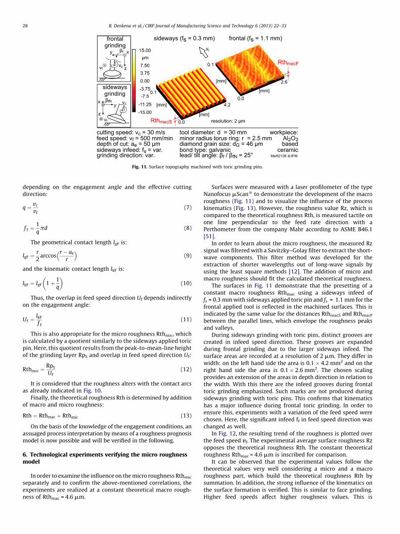
Fig. 11. Surface topography machined with toric grinding pins.
B. Denkena et al. / CIRP Journal of Manufacturing Science and Technology 6 (2013) 22–3328
depending on the engagement angle and the effective cuttingdirection:
q ¼ vc
vf(7)
f f ¼1
qpd (8)
The geometrical contact length lgF is:
lgF ¼r
2arccos
r � ae
r
� �(9)
and the kinematic contact length lkF is:
lkF ¼ lgF 1 þ 1
q
� �(10)
Thus, the overlap in feed speed direction Uf depends indirectlyon the engagement angle:
Uf ¼lkF
f f
(11)
This is also appropriate for the micro roughness Rthmic, whichis calculated by a quotient similarly to the sideways applied toricpin. Here, this quotient results from the peak-to-mean-line heightof the grinding layer RpS and overlap in feed speed direction Uf:
Rthmic ¼RpS
Uf(12)
It is considered that the roughness alters with the contact arcsas already indicated in Fig. 10.
Finally, the theoretical roughness Rth is determined by additionof macro and micro roughness:
Rth ¼ Rthmac þ Rthmic (13)
On the basis of the knowledge of the engagement conditions, anassuaged process interpretation by means of a roughness prognosismodel is now possible and will be verified in the following.
6. Technological experiments verifying the micro roughnessmodel
In order to examine the influence on the micro roughness Rthmic
separately and to confirm the above-mentioned correlations, theexperiments are realized at a constant theoretical macro rough-ness of Rthmac = 4.6 mm.
Surfaces were measured with a laser profilometer of the typeNanofocus mScan1 to demonstrate the development of the macroroughness (Fig. 11) and to visualize the influence of the processkinematics (Fig. 13). However, the roughness value Rz, which iscompared to the theoretical roughness Rth, is measured tactile onone line perpendicular to the feed rate direction with aPerthometer from the company Mahr according to ASME B46.1[51].
In order to learn about the micro roughness, the measured Rzsignal was filtered with a Savitzky–Golay filter to extract the short-wave components. This filter method was developed for theextraction of shorter wavelengths out of long-wave signals byusing the least square methods [12]. The addition of micro andmacro roughness should fit the calculated theoretical roughness.
The surfaces in Fig. 11 demonstrate that the presetting of aconstant macro roughness Rthmac using a sideways infeed offs = 0.3 mm with sideways applied toric pin and fs = 1.1 mm for thefrontal applied tool is reflected in the machined surfaces. This isindicated by the same value for the distances RthmacS and RthmacF
between the parallel lines, which envelope the roughness peaksand valleys.
During sideways grinding with toric pins, distinct grooves arecreated in infeed speed direction. These grooves are expandedduring frontal grinding due to the larger sideways infeed. Thesurface areas are recorded at a resolution of 2 mm. They differ inwidth: on the left hand side the area is 0.1 � 4.2 mm2 and on theright hand side the area is 0.1 � 2.6 mm2. The chosen scalingprovides an extension of the areas in depth direction in relation tothe width. With this there are the infeed grooves during frontaltoric grinding emphasized. Such marks are not produced duringsideways grinding with toric pins. This confirms that kinematicshas a major influence during frontal toric grinding. In order toensure this, experiments with a variation of the feed speed werechosen. Here, the significant infeed ff in feed speed direction waschanged as well.
In Fig. 12, the resulting trend of the roughness is plotted overthe feed speed vf. The experimental average surface roughness Rzopposes the theoretical roughness Rth. The constant theoreticalroughness Rthmac = 4.6 mm is inscribed for comparison.
It can be observed that the experimental values follow thetheoretical values very well considering a micro and a macroroughness part, which build the theoretical roughness Rth bysummation. In addition, the strong influence of the kinematics onthe surface formation is verified. This is similar to face grinding.Higher feed speeds affect higher roughness values. This is

Fig. 12. Variation of the feed speed during frontal toric grinding.
B. Denkena et al. / CIRP Journal of Manufacturing Science and Technology 6 (2013) 22–33 29
explainable due to the decreasing overlap in feed speed directionwith lower feed speeds.
The measured peak-to-mean-line height of the grinding layer RpS
causes up- and downturns around the average of the theoreticalroughness Rth. Particularly for this reason, the model reproducessurface enhancements by grain size reduction or grinding layertopography changes resulting from different bond types.
The theoretical roughness was calculated in a simplified formwith an overlap in the middle of the grinding path at the middleangle wm. If an average value of the entry angle we and middle anglewm is built instead, a flatter trend Rthmean results. This is closer tothe experimental Rz than to the trend with Rth.
In addition, these results are mirrored on the surfaces measuredusing a laser profilometer (Fig. 13).
The expected differences resulting from the feed speedvariation are clearly visible. The distance of the infeed groovesincreases with an increasing feed speed. The inscribed arrowlengths are in accordance with the infeed values in feed speeddirection, namely ff = 13 mm, 26 mm, 52 mm and 65 mm. Incontrast to this, for the sideways applied toric grinding pin it isexpected to observe hardly any differences during the feed speedvariation since the grinding topography has been imprinted in theworkpiece on the analogy to the peripheral grinding.
In Fig. 14, the experimental average surface roughness Rzand the theoretical roughness Rth are presented as a function of
Fig. 13. Surfaces generated with fro
the feed speed. The two roughness trends are close to eachother. Once again the theoretical macro roughness ofRthmac = 4.6 mm is shown. It becomes obvious that there is adistance between experiment and theoretical roughness whileonly considering the macro roughness, which disappears withthe consideration of the micro roughness introduced. There canonly be observed experimental up- and downturns representedby the minimum and maximum values. These result frommachine tool and grinding wheel tolerances in addition tometrological deviations.
The two approximately horizontal roughness trends of Rth andRz confirm that the kinematic influence of the feed speed vf versusthat of the infeed ff is subordinate during grinding with sidewaysapplied toric pin. As assumed, this is similar to peripheral grinding.During grinding with frontal applied toric pin, the roughnessvalues produced are up to 40% lower.
Fig. 15 shows the surfaces generated by sideways grinding.From top left to the bottom right the feed speed is increased by afactor of 5. Nevertheless, there is hardly any difference and theconstant trend is mirrored. Only uniform grinding paths areobservable.
Again, with a constant theoretical macro roughness Rthmac theinfluences of the grinding wheel topography on the microroughness Rthmic are examined to confirm the above-mentionedcorrelations. Two grain sizes and bond types are used. The
ntal applied toric grinding pin.

Fig. 14. Variation of the infeed speed during sideways applied toric grinding pin.
Fig. 15. Surfaces generated with sideways applied toric grinding pin.
B. Denkena et al. / CIRP Journal of Manufacturing Science and Technology 6 (2013) 22–3330
reduction of the grain size due to a smaller penetration depth offersa smaller roughness. The same applies to the change in bond typefrom galvanic to ceramic, because the cleft ceramic bonding has anadditional influence on the surface generation. The effects are
Fig. 16. Grain size and bond type influence
expected to have a stronger impact during grinding with sidewaysapplied toric pin. Their influence on the generated roughness Rz isshown in comparison to the theoretical roughness Rth and Rthmean
in Fig. 16 for frontal grinding with toric pins.
surface roughness in frontal grinding.

Fig. 17. Grain size and bond type influence surface roughness in frontal grinding.
Fig. 18. Ground and polished implant segment.
B. Denkena et al. / CIRP Journal of Manufacturing Science and Technology 6 (2013) 22–33 31
With the decrease of the grain size by more than 30% the middleroughness values decrease about 1 mm. For the change of the bondtype from galvanic to ceramic with a constant grain size ofdG = 46 mm there is a small enhancement of the roughness as well.Looking at the applied grinding layer topography, the model canpredict the expected roughness improvements. Rthmean, whichwas additionally determined, nearly lies on the same level as Rth.But this confirms once again that a grinding layer variation has aweaker impact during grinding with frontal applied toric pin and istherefore similar to face grinding. The topography variation hasmore influence on the surface generation during sideways grindingwith toric pin (Fig. 17).
In this case, the roughness enhancement is four times higherthan that with frontal applied toric pin and two times higher with aceramic bond type.
7. Machining implant segments
In order to prove the developed machining concept (Fig. 4)simplified ceramic samples were machined. Afterwards, these
samples were investigated in a wear test station at the Laboratoryof Biomechanics and Biomaterials of the Hannover Medical School[52–54].
With a frontal applied toric grinding pin and a flexible polishingtool high quality test components, as shown in Fig. 18, aremachined with an average surface finish of Ra < 10 nm and a shapewithin the tolerances �1 mm.
The wear is detected by a specifically developed rolling–glidingtest station [52], which simulates knee-like movements and loadsfor implant components, and could be improved significantly.Represented by the wear track depth, the wear is reduced by afactor of 30 in comparison to conventional pairings of CoCrMo-UHMWPE. Ceramic–ceramic combinations with a standard rough-ness Ra = 20 nm derived from measured ceramic hip implantsrealize a reduction by a factor of 3 or more (Fig. 19).
The volumetric wear based on gravimetric measurementsconfirms the above-mentioned trend. A reduction by a factor of 7 isachieved when using a ceramic–ceramic combination with aconventional surface instead of CoCrMo-UHMWPE. With the newmachining methods this reduction is even halved.

Fig. 19. Wear reduction.
B. Denkena et al. / CIRP Journal of Manufacturing Science and Technology 6 (2013) 22–3332
8. Conclusions
In order to machine high-quality, complex-shaped full-ceramic implants, it is fundamental to gain knowledge aboutthe grinding contact conditions and the connected developingroughness.
The results presented illustrate that the theoretical roughnessRth is in accordance with the experimental average surfaceroughness Rz. On the basis of the knowledge concerning theengagement conditions, an enhanced process evaluation ispossible due to a better understanding of the process. To optimizethe tool wear behavior the knowledge can be used for tool pathgeneration. Furthermore, there is a roughness model for theprocess design, which is experimentally verified.
During grinding with frontal applied toric pin with the samesideways infeed fs it is possible to achieve procedurally bettersurface qualities. Beside the fact that a more simple engagementgeometry is involved, different other correlations are moreadvantageous during sideways toric grinding. Main advantagesduring grinding with sideways applied toric pin result from theprocess area in which the roughness does not depend on the toolinclination and sensitivity to feed speed variations. These aspectsfavor the realization of a homogeneous grinding result by means ofa feed speed adaption for constant engagement conditions with asimultaneous, uniform, tool-wear oriented change of the tilt angle(bfN > bfN limit). The accessibility of small implant componentconcavities is ensured well.
In the experiments, the roughness was only affectedadversely when the grinding layer topography changed. Thisdisadvantage can be countered, for example, by the use of an in-process dressing technology. In contrast to frontal toric grinding,the narrower, parallel grinding paths seem to be more suitablefor the running direction dependent implant surface functio-nalization.
The realized machining processes with adaptable tools are thebasis for the machining of complex ceramic surfaces. With anautomated machining of free-formed surfaces the application oflow-wear ceramic endoprostheses in the knee joint is possible withan enhanced implant lifetime.
In addition, a transfer to other joints is feasible, for example,ankle, elbow or spinal disc as well as other implants such as dentalimplants and also non-medical applications such as mold and dieproductions, ceramic-coated turbine blades, or complex opticalcomponents [55–57].
Acknowledgments
This research is supported by the German Research Founda-tion (DFG) within the frame of the Collaborative ResearchCenter CRC 599 ‘‘Sustainable Bioresorbable and PermanentImplants of Metallic and Ceramic Materials’’. We appreciate thecooperation with our project partners from the Laboratory forBiomechanics and Biomaterials of the Medical University ofHannover.
References
[1] Schneider, S., Schmitt, G., Mau, H., Schmitt, H., Sabo, D., Richter, W., 2005,Pravalenz und Korrelate der Osteoarthrose in der BRD (Prevalence and corre-late of Osteoarthrosis in the Federal Republic of Germany (FRD)), Orthopade34, pp. 782–790.
[2] N.N., 2006, Gesundheit in Deutschland. Gesundheitsberichterstattung desBundes, ed. Robert-Koch-Institut.
[3] Beeres, M., 2010, BVMed - Jahresbericht 2009/2010 (BVMed - Annual report2009/2010), Bundesverband Medizintechnologie e.V, Berlin.
[4] Gorenoi, V., Schonermark, M.P., Hagen, A., 2009, Gelenkendo-prothesenregis-ter fur Deutschland (Register for Endoprostheses in Germany), SchriftenreiheHealth Technology Assessment (HTA) in der Bundesrepublik Deutschland,Medizinsche Hochschule Hannover, Geschaftsbereich Bundesministeriumfur Gesundheit, ed. Deutsches Institut fur Medizinische Dokumentation undInformation (DIMDI), Koln.
[5] Lidgren, L., Robertsson, O., W-Dahl, A., 2009, Annual Report 2009. The SwedishKnee Arthroplasty Register founded 1975. Lund University Hospital, Depart-ment of Orthopedics, Wallin & Dalholm AB, Lund.
[6] Lapcikova, M., Slouf, M., Dybal, J., Zolotarevova, E., Entlicher, G., Pokorny, D.,Gallo, J., Sosna, A., 2009, Nanometer Size Wear Debris Generated from UltraHigh Molecular Weight Polyethylene In Vivo, Wear, 266:349–355.
[7] Utzschneider, S., Harrasser, N., Schroeder, C., Mazoochian, F., Jansson, V., 2009,Wear of Contemporary Total Knee Replacements – A Knee Simulator Study ofSix Current Designs, Clinical Biomechanics, 24:583–588.
[8] Monschein, M., 2005. DLC verbessert Vertraglichkeit von Transplantaten. High-tech-Beschichtung gegen Abstoßung und Infektionen (DLC Enhances Compati-bility of Transplants. Hightech-Coating Against Rejection and Infection),Pressemitteilung 20.09.2005, retrieved April 11, 2010, from: http://pressetext.at/news/050920012/dlc-verbessert-vertraeglichkeit-von-transplantaten/?phrase=Transplantaten..
[9] Weiner, M., 2006, Die Diamant-Prothesen [The Diamond Prostheses]. Fraun-hofer-Magazin, 3:46–47.
[10] Reich, J., Hovy, L., Lindenmaier, H.L., Zeller, R., Schwiesau, J., Thomas, P., Grupp,T.M., 2010, Preclinical Evaluation of Coated Knee Implants for Allergic Patients,Orthopaedics, 39/5: 495–502.
[11] Klingbeil, K., Hennig, O., Nassutt, R., Grundei, H., 2005, Cera-Metal–ein neuerkeramischer Gleitpartner fur die Endoprothetik ohne Bruchrisiko. Implantatefur die Orthopadie und Traumatologie (Cera-metal – a New Ceramic GlidingPartner for Endoprosthetics Without Risk of Breakage. Implants for Orthope-dics and Traumatology), Biomaterialien, Internationale Biomechanik- undBiomaterial-Tage 8. -9. Juli, Klinik fur Orthopadie und Sportorthopadie,Munchen.

B. Denkena et al. / CIRP Journal of Manufacturing Science and Technology 6 (2013) 22–33 33
[12] N.N., 2010, Curve fitting toolbox 3.0 (Realease 2010). User’s Guide. Online only.Mathworks Inc., URL: http://www.mathworks.com/help/pdf_doc/curvefit/curvefit.pdf, 23.09.2010.
[13] N.N., 2010, Produktinformation Oxinium, Fa. Smith & Nephew, Memphis USA,retrieved Junr 30, 2010, from: http://global.smith-nephew.com/us/OXINIUM_OXIDIZED ZIRCONIUM_24484.htm.
[14] Lee, M.-C., Ahn, J.-W., 2007, Ceramic Femoral Prosthesis in TKA – Present andFuture, Bioceramics and Alternative Bearings in Joint Arthroplasty, in: Pro-ceedings 12. Biolox Symposium, pp.123–132.
[15] Rieger, W., 2001, Ceramics in Orthopedics – 30 Years of Evolution andExperience, World Tribology Forum in Arthroplasty, Reprint from Rieker, C.,Oberholzer, S., Wyss, U. (Eds.), Hans Huber Verlag, Bern.
[16] Merkert, P., Kuntz, M., 2006, Future Applications in Ceramics, Ceramic inOrthopaedics – Bioceramics and Alternative Bearings in Joint Arthroplasty.Proceedings 11. Biolox Symposium, pp.283–288.
[17] Kuntz, M., 2005, Future Ceramic Strategies 10. Biolox Symposium, Session 6.New Applications for Ceramics, pp.201–206.
[18] Heinzel, C., 2009, Schleifprozesse verstehen: Zum Stand der Modellbildung undSimulation sowie unterstutzender experimenteller Methoden (Understandingof Grinding Processes: Status in Modeling and Simulation as well as AssistingExperimental Methods), professorial dissertation, Universitat Bremen.
[19] Zander, J., 1995, Potenziale beim Mehrachsen-Frasen mit Toruswerkzeugen imFormenbau (Potentials in Multi-axes Milling with torus tools in die milling),Thesis, Universitat Aachen.
[20] Behrens, B.-A., Bach, Fr.-W., Denkena, B., Mohwald, K., Deisser, T.A., Kramer, N.,Bistron, M., 2009, Manufacturing of Reinforced High Precision Forging Dies,steel research international 80/12, pp. 878–884.
[21] Denkena, B., de Leon, L., Wang, B., Krawczyk, T., 2010, Manufacturing of Riblet-Structures by Profile Grinding with Metal Bonded Wheels, in: Proceedings ofthe 10th International Conference of the European Society for PrecisionEngineering and Nanotechnology (euspen) (Vol. 2, 31.05.-04.06., Delft,Netherlands), pp.295–298.
[22] Boß, V., 2007, Werkzeugwege fur das Bandschleifen von Freiformflachen (ToolPaths for Belt Grinding of Free Formed Surfaces), PhD-Thesis, Leibniz Uni-versitat Hannover.
[23] Klocke, F., Dambon, O., Hunten, M., 2009, Integrative Fertigung von Mikroop-tiken (Integrative Manufaturing of Micro Optics), wt Werkstattstechnik online99 H6, pp. 421–425.
[24] Schmidt, C., 2008, Koordinatenschleifen dentalkeramischer Werkstoffe mitkleinen Diamantwerkzeugen (Jig Grinding of Dental Ceramic Materials withSmall Diamaond Tools), PhD-Thesis, Universitat Aachen.
[25] Weinert, K., Jansen, T., Blum, H., Rademacher, A., 2007, Simulation BasedOptimization of the NC-Shape Grinding Process with Toroid Grinding Wheels,Production Engineering, 3:245–252.
[26] Okuyama, S., Kitajima, T., Yui, A., 2004, Theoretical Study on the Effect of FormError of Grinding Wheel Surfaces under Free Form Grinding, Key EngineeringMaterials, 257–258:147–152.
[27] Stimpel, F., 2009. Technologische Kenngroßen fur das kontinuierliche Walzs-chleifen von Evolventenverzahnungen (Technological Characteristics for theContinuous Generating Grinding of Involute Gears), PhD Thesis, Leibniz Uni-versitat Hannover.
[28] Denkena, B., Deichmueller, M., de Payrebrune, K.M., Kroger, M., Wiedemann,S., Schroeder, A., Carstensen, C., 2010, Determination of Static and DynamicDeflections in Tool Grinding using a Dexel-Based Material Removal Simula-tion, 2nd International Conference on Process Machine Interactions (10.-11.06., Vancouver, Canada), .
[29] Wang, B., 2010, Herstellung funktionaler Riblet-Strukturen durch Profilschlei-fen (Manufacturing of Functional Riblet-Patterns by Profile Grinding), PhDThesis, Leibniz Universitat Hannover.
[30] Klocke, F., Duscha, M., Hoffmann, F., Wegner, H., Zeppenfeld, C., 2008, Machine– Grinding Wheel – Workpiece Interaction in Speed Stroke Grinding, 1stInternational Conference on Process Machine Interactions (03.-04.09., Hann-over), pp.259–266.
[31] Duscha, M., Klocke, F., Wegner, H., 2009, Erfassung und Charakterisierung derSchleifscheibentopographie fur die anwendungs-gerechte Prozessauslegung[Detection and Characterization of the Grinding Wheel Topography for anApplication-oriented Process Development]. Diamond Business, 1/2: 28–32.36–40.
[32] Hubert, C., Mauren, F., van der Meer, M., Hahmann, D., Rickens, K., Mutlugunes,Y., Hahmann, W.-C., Pekarek, M., 2009, WGP-Arbeitskreis, Bearbeitung sprod-harter Werkstoffe – Charakterisierung von Schleifscheibentopographien ausfertigungstechnischer Sicht (German Academic Society for Production Engi-neering (WGP) – Research Group, Machining Brittle-hard Materials – Charac-terization of Grinding Wheel Topographies According to Production-orientated Aspects), Diamant Hochleistungswerkzeuge Dihw, 1/IV: 40–47.
[33] Denkena, B., Kramer, N., 2008. Wear Characteristics of Diamond Grain-Typesin Steel-Ceramic-Compound Grinding, International Symposium on Friction,Wear and Wear Protection, 09.-11.04., Aachen, pp. 719–725.
[34] Hou, Z.B., Kommanduri, R., 2003, On the Mechanics of the Grinding Process –Part I. Stochastic Nature of the Grinding Process, International Journal ofMachine Tools and Manufacture, 43:1579–1593.
[35] Sakakura, M., Tsukamoto, S., Fujiwara, T., Inasaki, I., 2008, Visual Simulation ofGrinding Process, Proceedings of the Institution of Mechanical Engineers PartB Journal of Engineering Manufacture, 222/10: 1233–1239.
[36] Aurich, J.C., Biermann, D., Blum, H., Brecher, C., Carstensen, C., Denkena, B.,Klocke, F., Kroger, M., Steinmann, P., Weinert, K., 2009, Modelling and Simu-lation of Process – Machine Interaction in Grinding, Production Engineering,3:111–120.
[37] Chakrabarti, S., Paul, S., 2008, Numerical Modelling of Surface Topography inSuperabrasive Grinding, International Journal of Advanced ManufacturingTechnology, 39:29–38.
[38] Chen, X., Rowe, W.-B., Mills, B., Allanson, D.-R., 1998, Analysis and Simulationof the Grinding Process. Part IV: Effects of the Wheel Wear, InternationalJournal of Machine Tools and Manufacture, 38:41–49.
[39] Hegeman, J.B.J.-W., 2000, Fundamentals of Grinding – Surface Conditions ofGround Materials, PhD-Thesis, Universitat Groningen.
[40] Kassen, G., 1969, Beschreibung der elementaren Kinematik des Schleifvor-ganges (Description of the Fundamental Kinematics of the Grinding Process),PhD Thesis, Universitat Aachen.
[41] Law, S.-S., Wu, S.-M., 1973, Simulation Study of the Grinding Process, ASMEJournal of Engineering for Industry, 95:972–978.
[42] Yoshikawa, H., Sata, T., 1968, Simulated Grinding Process by Monte CarloMethod, Annals of the CIRP, 16:297–302.
[43] Koshy, P., Ives, L.-K., Jahanmir, S., 1999, Simulation of Diamond-GroundSurface, International Journal of Machine Tools and Manufacture, 39:1451–1470.
[44] Agarwal, S., Venkateswara Rao, P., 2005, A New Surface Roughness PredictionModel for Ceramic Grinding, Journal of Engineering Manufacture Institute ofMechanical Engineering, 219 B:811–821.
[45] Hecker, R.L., Liang, S.Y., 2003, Predictive Modeling of Surface Roughness inGrinding, International Journal of Machine Tools and Manufacture, 43:755–761.
[46] Salisbury, E.J., Domala, K.V., Moon, K.S., Miller, M.H., Sutherland, J.W., 2001, AThree-Dimensional Model for the Surface Texture in Surface Grinding, Part 1:Surface Generation Model and Part 2: Grinding Wheel Surface Texture Model,Transactions of the ASME, 123:576–581. 582–590.
[47] Brinksmeier, E., Aurich, J.C., Govekar, E., Heinzel, C., Hoffmeister, H.-W., Klocke,F., Peters, J., Rentsch, R., Stephenson, D.J., Uhlmann, E., Weinert, K., Wittmann,M., 2006, Advances in modelling and simulation of grinding processes, Annalsof the CIRP, 55/2: 12–14.
[48] Denkena, B., De Leon, L., Turger, A., Behrens, L., 2010, Prediction of contactconditions and theoretical roughness in manufacturing of complex implantsby toric grinding tools, International Journal of Machine Tools and Manufac-ture, 50/7: 630–636.
[49] Reichstein, M., 2008, Schleifen miniaturisierter Bauteile (Grinding of Minia-turized Components), PhD Thesis, Leibniz Universitat Hannover.
[50] Denkena, B., Tonshoff, H.K., 2011, Spanen – Grundlagen, 3. bearb. u. erw.Auflage, Springer Verlag 2011, VDI-Buch.
[51] ASME B46.1 – 2002, 2003, Surface Texture, Surface Roughness, Waviness andLay, American Society of Mechanical Engineers.
[52] Denkena, B., Reichstein, M., van der Meer, M., Ostermeier, S., Hurschler, C.,2008, Wear Analysis and Finishing of Bioceramic Implant Surfaces, MedicineMeets Engineering: Proceedings of the 2nd Conference on Applied Biome-chanics Regensburg (March), pp.75–82.
[53] Denkena, B., van der Meer, M., 2009, Diamond tools for the grinding ofcomplex ceramic implant surfaces, Advances in Abrasive Technology XII:12th International Symposium on Advances in Abrasive Technology (ISAAT)(27–30 September, Gold Coast, Australia, vols. 76–78), pp.33–37.
[54] Richter, B.I., Ostermeier, S., Turger, A., Denkena, B., Hurschler, C., 2010, Arolling–gliding wear simulator for the investigation of tribological materialpairings for application in total knee arthroplasty, BioMedical OnLine, 9/24.
[55] Denkena, B., de Leon, L., Behrens, L., 2010, Contact conditions in 5-axis-grinding of double curved surfaces with toric grinding wheels, Advances inAbrasive Technology XIII: 13th International Symposium on Advances inAbrasive Technology (ISAAT) (19–22 September, Taipei, Taiwan, vols. 126–128), pp.41–46.
[56] Krause, S., 2008, Hochglanzende Freiformflachen auf Stahlwerkzeugen (HighGloss Finished Free Formed Surface on Steel Molds), Pressemitteilung20.11.2008, Frauhnhofer IPT, retrieved September 13, 2010, from: http://www.ipt.fraunhofer.de/press/Archiv/EuroMold2008HochglaenzendeFreiform-flaechenaufStahlwerkzeugen.jsp.
[57] N.N., 2008, Hohere Energieausbeute dank Keramik – Zweischicht-systemschutzt Rekordturbine gegen Hitze und Oxidation (higher Energy EfficiencyOwing to Ceramics – Dubble Coating System Protects Record Turbine againstHeat and Oxidation), Pressemitteilung vom 10.03.2008, ed. Fa. Siemens, re-trieved September 20, 2010, from: http://www.siemens.com/press/de/presse-bilder/?press=/de/pressebilder/bilder-photonews/2008/pn200807.php.
[58] Chen, X., Rowe, W.-B., 1999, Modelling Surface Roughness Improvement inGrinding, Proceedings of the Institution of Mechanical Engineers, 213 B:93–96.


![TORIC, GLOBAL, AND GENERALIZED SYZmath.bu.edu/people/lau/papers/Toric global and generalized SYZ.pdf · of wall-crossing phenomenons was rst observed by Auroux [2] in a non-toric](https://img.pdfslide.us/doc/110x75/6071f909ebb1de05fe6d3ecb/toric-global-and-generalized-global-and-generalized-syzpdf-of-wall-crossing.jpg)