Embed Size (px)
Citation preview
AFRL-RX-WP-JA-2016-0273
A ROTATIONAL AND AXIAL MOTION SYSTEM LOAD FRAME INSERT FOR IN SITU HIGH ENERGY X-RAY STUDIES (POSTPRINT) Paul A. Shade, Jay C. Schuren, and Todd J. Turner AFRL/RX Basil Blank PulseRay Peter Kenesei, Kurt Goetze, Ulrich Lienert, and Jonathan Almer Advanced Photon Source Robert M. Suter and Jonathan Lind Carnegie Mellon University Joel V. Bernier, Shiu Fai Li, and Jonathan Lind Lawrence Livermore National Laboratory
15 JULY 2015 Interim Report
Distribution Statement A.
Approved for public release: distribution unlimited.
© 2015 AIP PUBLISHING LLC (STINFO COPY)
AIR FORCE RESEARCH LABORATORY MATERIALS AND MANUFACTURING DIRECTORATE
WRIGHT-PATTERSON AIR FORCE BASE, OH 45433-7750 AIR FORCE MATERIEL COMMAND
UNITED STATES AIR FORCE

REPORT DOCUMENTATION PAGE Form Approved OMB No. 0704-0188
The public reporting burden for this collection of information is estimated to average 1 hour per response, including the time for reviewing instructions, searching existing data sources, gathering and maintaining the data needed, and completing and reviewing the collection of information. Send comments regarding this burden estimate or any other aspect of this collection of information, including suggestions for reducing this burden, to Department of Defense, Washington Headquarters Services, Directorate for Information Operations and Reports (0704-0188), 1215 Jefferson Davis Highway, Suite 1204, Arlington, VA 22202-4302. Respondents should be aware that notwithstanding any other provision of law, no person shall be subject to any penalty for failing to comply with a collection of information if it does not display a currently valid OMB control number. PLEASE DO NOT RETURN YOUR FORM TO THE ABOVE ADDRESS.
1. REPORT DATE (DD-MM-YY) 2. REPORT TYPE 3. DATES COVERED (From - To)
15 July 2015 Interim 30 September 2014 – 15 June 2015 4. TITLE AND SUBTITLE
A ROTATIONAL AND AXIAL MOTION SYSTEM LOAD FRAME INSERT FOR IN SITU HIGH ENERGY X-RAY STUDIES (POSTPRINT)
5a. CONTRACT NUMBER FA8650-14-D-5205-0001
5b. GRANT NUMBER
5c. PROGRAM ELEMENT NUMBER 62102F
6. AUTHOR(S)
1) Paul A. Shade, Jay C. Schuren, and Todd J. Turner – AFRL/RX
2) Basil Blank – PulseRay (continued on page 2)
5d. PROJECT NUMBER 4349
5e. TASK NUMBER 0001 5f. WORK UNIT NUMBER
X0U5 7. PERFORMING ORGANIZATION NAME(S) AND ADDRESS(ES) 8. PERFORMING ORGANIZATION REPORT NUMBER
1) AFRL/RX Wright-Patterson AFB, OH 45433-7750
2) PulseRay, 4583 State Route 414 Beaver Dams, NY 14812 (continued on page 2)
9. SPONSORING/MONITORING AGENCY NAME(S) AND ADDRESS(ES) 10. SPONSORING/MONITORING AGENCY ACRONYM(S)
Air Force Research Laboratory Materials and Manufacturing Directorate Wright-Patterson Air Force Base, OH 45433-7750 Air Force Materiel Command United States Air Force
AFRL/RXCM 11. SPONSORING/MONITORING AGENCY REPORT NUMBER(S)
AFRL-RX-WP-JA-2016-0273
12. DISTRIBUTION/AVAILABILITY STATEMENT Distribution Statement A. Approved for public release: distribution unlimited.
13. SUPPLEMENTARY NOTES PA Case Number: 88ABW-2015-3613; Clearance Date: 15 July 2015. This document contains color. Journal article published in Review of Scientific Instruments, Vol. 86, No. 9, 8 Sep 2015. © 2015 AIP Publishing LLC. The U.S. Government is joint author of the work and has the right to use, modify, reproduce, release, perform, display, or disclose the work. The final publication is available at http://dx.doi.org/10.1063/1.4927855
14. ABSTRACT (Maximum 200 words) High energy x-ray characterization methods hold great potential for gaining insight into the behavior of materials and providing comparison datasets for the validation and development of mesoscale modeling tools. A suite of techniques have been developed by the x-ray community for characterizing the 3D structure and micromechanical state of polycrystalline materials; however, combining these techniques with in situ mechanical testing under well characterized and controlled boundary conditions has been challenging due to experimental design requirements, which demand new high-precision hardware as well as access to high-energy x-ray beamlines. We describe the design and performance of a load frame insert with a rotational and axial motion system that has been developed to meet these requirements. An example dataset from a deforming titanium alloy demonstrates the new capability.
15. SUBJECT TERMS High energy x-ray; 3D structure; micromechanical; polycrystalline materials; in situ mechanical testing; titanium alloy
16. SECURITY CLASSIFICATION OF: 17. LIMITATION OF ABSTRACT:
SAR
18. NUMBER OF PAGES
12
19a. NAME OF RESPONSIBLE PERSON (Monitor) a. REPORT Unclassified
b. ABSTRACT Unclassified
c. THIS PAGE Unclassified
Bill Song 19b. TELEPHONE NUMBER (Include Area Code)
(937) 2551351
Standard Form 298 (Rev. 8-98) Prescribed by ANSI Std. Z39-18
REPORT DOCUMENTATION PAGE Cont’d 6. AUTHOR(S)
3) Peter Kenesei, Kurt Goetze, Ulrich Lienert, and Jonathan Almer - APS 4) Robert M. Suter and Jonathan Lind - CMU 5) Joel V. Bernier, Shiu Fai Li, and Jonathan Lind - LLNL
7. PERFORMING ORGANIZATION NAME(S) AND ADDRESS(ES)
3) Advanced Photon Source Argonne National Laboratory 9700 S Cass Ave, Lemont, IL 60439 4) Carnegie Mellon University 5000 Forbes Ave, Pittsburgh, PA 15213 5) Lawrence Livermore National Laboratory 7000 East Ave, Livermore, CA 94550
Standard Form 298 (Rev. 8-98) Prescribed by ANSI Std. Z39-18
REVIEW OF SCIENTIFIC INSTRUMENTS 86, 093902 (2015)
A rotational and axial motion system load frame insert for in situ highenergy x-ray studies
Paul A. Shade,1,a) Basil Blank,2 Jay C. Schuren,1,b) Todd J. Turner,1 Peter Kenesei,3Kurt Goetze,3 Robert M. Suter,4 Joel V. Bernier,5 Shiu Fai Li,5,c) Jonathan Lind,4,5
Ulrich Lienert,3,d) and Jonathan Almer31Materials and Manufacturing Directorate, Air Force Research Laboratory, Wright-Patterson AFB,Ohio 45433, USA2PulseRay, Beaver Dams, New York 14812, USA3Advanced Photon Source, Argonne National Laboratory, Argonne, Illinois 60439, USA4Carnegie Mellon University, Pittsburgh, Pennsylvania 15213, USA5Engineering Directorate, Lawrence Livermore National Laboratory, Livermore, California 94550, USA
(Received 12 July 2015; accepted 22 July 2015; published online 8 September 2015)
High energy x-ray characterization methods hold great potential for gaining insight into the behaviorof materials and providing comparison datasets for the validation and development of mesoscalemodeling tools. A suite of techniques have been developed by the x-ray community for character-izing the 3D structure and micromechanical state of polycrystalline materials; however, combiningthese techniques with in situ mechanical testing under well characterized and controlled boundaryconditions has been challenging due to experimental design requirements, which demand newhigh-precision hardware as well as access to high-energy x-ray beamlines. We describe the design andperformance of a load frame insert with a rotational and axial motion system that has been developedto meet these requirements. An example dataset from a deforming titanium alloy demonstrates thenew capability. C 2015 AIP Publishing LLC. [http://dx.doi.org/10.1063/1.4927855]
I. INTRODUCTION
There is a great deal of interest within the materialscommunity to develop mesoscale modeling tools which aresensitive to the underlying microstructure. For example, adop-tion of an integrated computational materials engineering(ICME) approach to design of structural components is depen-dent on such a capability.1–6 Development of trusted micro-structure-sensitive deformation models may provide improvedpredictions of materials behavior, e.g., strength and damageresistance, enabling structural materials to be used more effec-tively and efficiently. While development of mesoscale modelshas been a major thrust of the materials community for severaldecades, these models have lacked the necessary multi-scaleexperimental validation, thus precluding design engineersfrom adopting them due to unacceptable risk factors. Lookingforward, advanced materials characterization methods arepositioned to play a critical role in the validation and futuredevelopment of mesoscale models and the long term goal oftransitioning such modeling tools to the design community.5–20
One particular suite of experimental techniques that prom-ises to be extremely fruitful in this endeavor is known as highenergy diffraction microscopy (HEDM) or three-dimensionalx-ray diffraction (3DXRD).6,21–23 These techniques utilizehigh energy monochromatic synchrotron radiation and area
a)Author to whom correspondence should be addressed. Electronic mail:[email protected]
b)Present address: Nutonian, Inc., Somerville, Massachusetts 02144, USA.c)Present address: Human Diagnosis Project, San Francisco, California
94110, USA.d)Present address: DESY, Photon Science, Hamburg, Germany.
detectors in transmission geometry to collect diffracted x-rays as a function of sample rotation. This combination al-lows individual grain information from ∼mm3 volumes ofpolycrystalline materials to be determined non-destructively.When combined in situ with mechanical testing techniques,HEDM (or 3DXRD) offers a powerful tool to evaluate theinternal structure and micromechanical state of a deformingmaterial. To date, this collection of methods have largely beenthought of as individual techniques, including far field HEDM(ff-HEDM) to measure the average elastic strain tensor ofindividual grains (stress tensor with known elastic stiffnessmatrix)24–27 and near field HEDM (nf-HEDM) to map thestructure and local crystallographic orientation within andbetween grains.21,28,29 While the individual techniques arevaluable on their own, the concurrent application of nf-HEDM,ff-HEDM, and others such as absorption micro-computedtomography (µ-CT) for mapping the structure of voids, cracks,and/or inclusions which may be present,30 can provide incred-ibly rich datasets from which to develop and validate micro-structure sensitive materials models.
The key factor that has restricted the collection of suchintegrated multimodal HEDM datasets in situ with traditionalmechanical testing equipment is the stringent set of mechan-ical and geometrical requirements placed on the experimentalsetup. The requirements include precisely (≤0.1◦ precision)rotating a specimen over a range of 180◦ or more while simulta-neously applying a mechanical load under known and control-lable boundary conditions. Furthermore, the apparatus itselfmust not obstruct the incident, transmitted or diffracted x-ray signals and must allow the near field detector to be asclose as 5 mm downstream of the specimen. In this paper,we describe a rotational and axial motion system (RAMS)31
0034-6748/2015/86(9)/093902/8/$30.00 86, 093902-1 © 2015 AIP Publishing LLC1
Distribution A. Approved for public release (PA): distribution unlimited.
093902-2 Shade et al. Rev. Sci. Instrum. 86, 093902 (2015)
that we have developed to enable the concurrent application ofhigh energy x-ray methods (ff-HEDM, nf-HEDM, µ-CT, andothers) while conducting a conventional tensile or compressiveloading experiment in situ.
II. DESIGN
The promise of advanced in situ characterization hasinspired the development of a variety of complex experimentalhardware at x-ray and neutron beamline facilities, each devel-oped to accommodate a specific set of experimental require-ments for the particular application. One solution for rotationof a sample with in situ mechanical testing has been to attacha load frame to the top of a rotation stage.32–35 This solution isnot practical for the current experimental requirements, as thelocation of the near field detector (∼5 mm from the specimen)would limit the rotation range of the load frame to a smallangular window beyond which the support columns wouldcause interference. At the same time, simple ad hoc arrange-ments have demonstrated the possibility and value of in situloading that is compatible with near field measurements.5,36,37
A more elegant solution is to rotate the specimen grips of ageneral purpose load frame synchronously while the rest ofthe load frame remains stationary;38,39 this has the advantage
of allowing complete rotation about the loading axis while alsoallowing more sophisticated loading control modes.
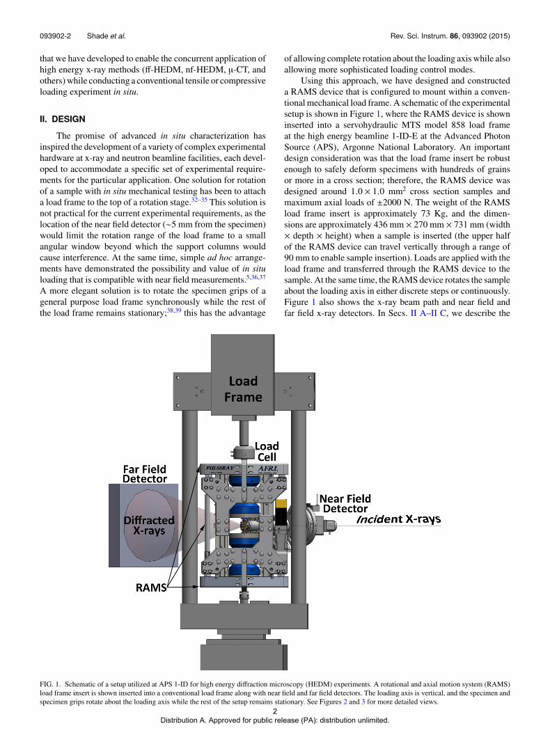
Using this approach, we have designed and constructeda RAMS device that is configured to mount within a conven-tional mechanical load frame. A schematic of the experimentalsetup is shown in Figure 1, where the RAMS device is showninserted into a servohydraulic MTS model 858 load frameat the high energy beamline 1-ID-E at the Advanced PhotonSource (APS), Argonne National Laboratory. An importantdesign consideration was that the load frame insert be robustenough to safely deform specimens with hundreds of grainsor more in a cross section; therefore, the RAMS device wasdesigned around 1.0 × 1.0 mm2 cross section samples andmaximum axial loads of ±2000 N. The weight of the RAMSload frame insert is approximately 73 Kg, and the dimen-sions are approximately 436 mm × 270 mm × 731 mm (width× depth × height) when a sample is inserted (the upper halfof the RAMS device can travel vertically through a range of90 mm to enable sample insertion). Loads are applied with theload frame and transferred through the RAMS device to thesample. At the same time, the RAMS device rotates the sampleabout the loading axis in either discrete steps or continuously.Figure 1 also shows the x-ray beam path and near field andfar field x-ray detectors. In Secs. II A–II C, we describe the
FIG. 1. Schematic of a setup utilized at APS 1-ID for high energy diffraction microscopy (HEDM) experiments. A rotational and axial motion system (RAMS)load frame insert is shown inserted into a conventional load frame along with near field and far field detectors. The loading axis is vertical, and the specimen andspecimen grips rotate about the loading axis while the rest of the setup remains stationary. See Figures 2 and 3 for more detailed views.
2 Distribution A. Approved for public release (PA): distribution unlimited.
093902-3 Shade et al. Rev. Sci. Instrum. 86, 093902 (2015)
various design criteria for the device and the correspondingdesign aspects that were utilized to meet them.
A. Rotation
The primary design constraint was to enable continuousrotation of the sample while independently and simultaneouslyapplying an axial load. The radial and axial error motions(e.g., eccentricity and wobble) during rotation of a samplethat has been centered on the rotation axis must be mini-mized.40,41 These errors will lead to uncertainties in the HEDMmeasurements,27,42 and potentially information that is missedaltogether. The latter situation may occur when using a linefocused (∼few µm) x-ray beam if the rotation axis is notorthogonal to the line focus. At the same time, the system mustbe designed to remain rigid against the expected axial and non-axial loads.43,44
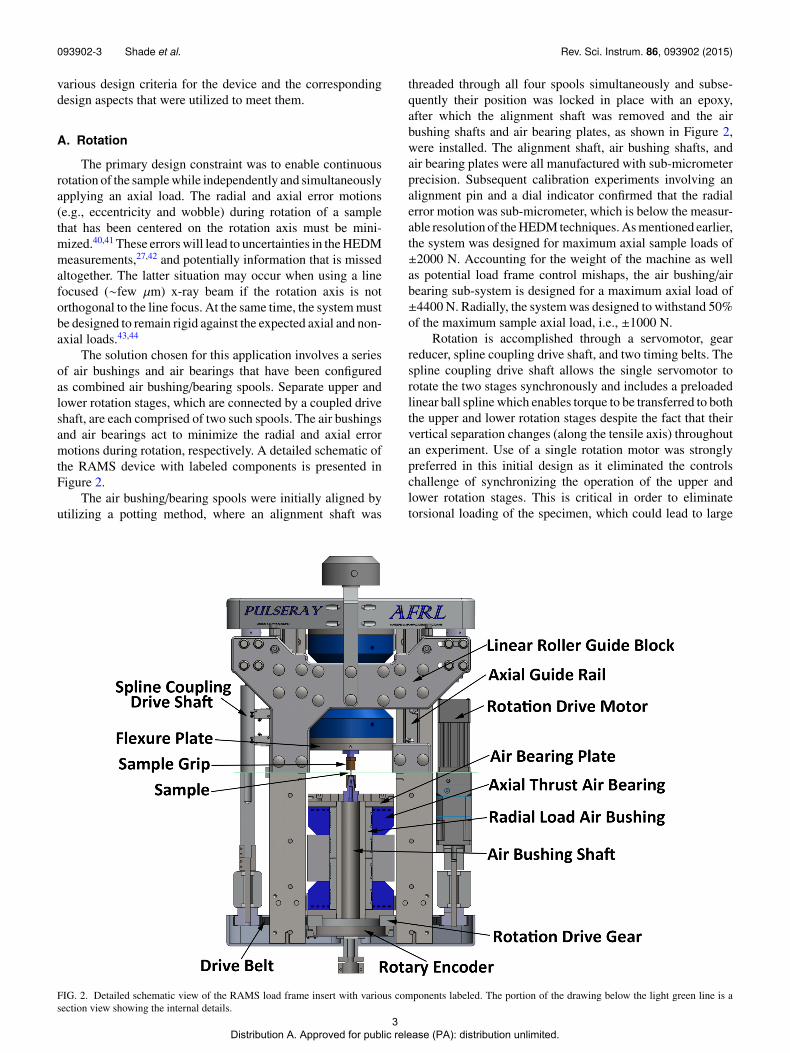
The solution chosen for this application involves a seriesof air bushings and air bearings that have been configuredas combined air bushing/bearing spools. Separate upper andlower rotation stages, which are connected by a coupled driveshaft, are each comprised of two such spools. The air bushingsand air bearings act to minimize the radial and axial errormotions during rotation, respectively. A detailed schematic ofthe RAMS device with labeled components is presented inFigure 2.
The air bushing/bearing spools were initially aligned byutilizing a potting method, where an alignment shaft was
threaded through all four spools simultaneously and subse-quently their position was locked in place with an epoxy,after which the alignment shaft was removed and the airbushing shafts and air bearing plates, as shown in Figure 2,were installed. The alignment shaft, air bushing shafts, andair bearing plates were all manufactured with sub-micrometerprecision. Subsequent calibration experiments involving analignment pin and a dial indicator confirmed that the radialerror motion was sub-micrometer, which is below the measur-able resolution of the HEDM techniques. As mentioned earlier,the system was designed for maximum axial sample loads of±2000 N. Accounting for the weight of the machine as wellas potential load frame control mishaps, the air bushing/airbearing sub-system is designed for a maximum axial load of±4400 N. Radially, the system was designed to withstand 50%of the maximum sample axial load, i.e., ±1000 N.
Rotation is accomplished through a servomotor, gearreducer, spline coupling drive shaft, and two timing belts. Thespline coupling drive shaft allows the single servomotor torotate the two stages synchronously and includes a preloadedlinear ball spline which enables torque to be transferred to boththe upper and lower rotation stages despite the fact that theirvertical separation changes (along the tensile axis) throughoutan experiment. Use of a single rotation motor was stronglypreferred in this initial design as it eliminated the controlschallenge of synchronizing the operation of the upper andlower rotation stages. This is critical in order to eliminatetorsional loading of the specimen, which could lead to large
FIG. 2. Detailed schematic view of the RAMS load frame insert with various components labeled. The portion of the drawing below the light green line is asection view showing the internal details.
3 Distribution A. Approved for public release (PA): distribution unlimited.
093902-4 Shade et al. Rev. Sci. Instrum. 86, 093902 (2015)
stresses for the typical sample cross sections used in HEDMexperiments (∼1 mm2). The rotation position is monitored witha pair of rotary encoders. With this setup, the rotation precisionis better than 0.1◦ at a maximum rotation rate of 10◦/s. Futureimplementations of this device will utilize metallic gears ratherthan timing belts, as well as an optimized gear ratio, rotaryencoder, and rotary encoder read head, which should enableimproved precision at higher rotation rates.
B. Coaxial translation and alignment
Another critical design constraint was the coaxiality ofthe upper and lower rotation stages, as any deviations wouldimpart bending stresses on the sample during rotation. Thepotting method used to align the upper and lower rotationstages was described in Section II A. This alignment wasmaintained during tension/compression testing through theuse of an axial guide rail and linear roller guide block, asshown in Figure 2. This design utilized linear roller bearingsto ensure that the vertical translation axis (tensile axis) of theupper rotation stage remained parallel to the coaxial rotationaxes of the two rotation stages.
A related requirement was for the upper and lower sam-ple grips, which, respectively, are attached to the upper andlower rotation stages, to be aligned such that the center of asample mounted within the grips would be on the center of
the rotation axis. The reasons for this are twofold. First, thecenter of the sample must be near the rotation axis so thata region of interest within the sample does not rotate out ofthe field of view (defined by the beam width of ∼1.5 mm)during a measurement. Second, and perhaps more important,the centerlines of the upper and lower sample grips must becoaxial with each other in order to prevent non-axial loadingof the sample during sample installation. Again, sample crosssections are typically 1 mm2 or less, so small loads can leadto large stresses. The specimen tolerances in the grip regionare relatively tight (±12.5 µm) to ensure proper grip force andrepeatable position, so the alignment precision must be on thescale of a few micrometers or less. This was accomplishedthrough the use of a flexure plate design,45,46 as shown inFigures 2 and 3.
The flexure plates were constructed by machining a seriesof channels, effectively producing an array of springs creatingtwo orthogonal adjustment directions within the plane of theplate (orthogonal to the tensile axis), as can be seen in Figure 3.The design challenge for optimizing the stiffness of the flexureplate in the adjustment directions was to balance the opposingobjectives of being as stiff as possible (in order to apply rigidboundary conditions for a tension/compression test), whilemaintaining sufficient compliance in order to practically beable to make the necessary translational adjustments. Thechosen solution was to design for a relatively rigid translational
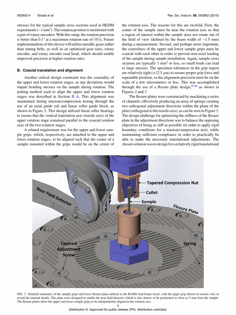
FIG. 3. Detailed schematic of the sample grips and lower flexure plate utilized in the RAMS load frame insert, with the upper grip shown in section view toreveal the internal details. The grips were designed to enable the near field detector, which is also shown, to be positioned as close as 5 mm from the sample.The flexure plates allow the upper and lower sample grips to be independently aligned to the rotation axis.
4 Distribution A. Approved for public release (PA): distribution unlimited.
093902-5 Shade et al. Rev. Sci. Instrum. 86, 093902 (2015)
stiffness of 1300 N/µm in the adjustment directions and utilizethe mechanical advantage of a tapered adjustment screw, asshown in Figure 3, to make the necessary adjustments totranslate the centerline of the grips to be coaxial with therotation axis. This resulted in approximately 1 µm of trans-lational travel per 90◦ turn of the tapered adjustment screw.An alignment procedure that involved use of a dial indicatorto monitor the position of a pin inserted into the grip duringstage rotation was utilized. A best practice for achieving thefinest sensitivity with this alignment procedure was found tobe to slightly over-compensate with the initial correction, thensubsequently repeat the procedure and make a relatively smallcorrection in the opposing direction.
C. Minimalist grip design
A third major design constraint was to utilize a geometrythat enabled the near field detector to sit as close as possibleto the specimen during an experiment.28 This required thedevelopment of sample grips with minimal radial dimensions.The grip design chosen is shown in Figure 3, where the nearfield detector is also shown for reference.
The sample grip design utilizes an interference fit, wherea collet and tapered compression nut act to impart increasingpressure on the grip region of the specimen as increasingtorque is applied to the tapered compression nut. The sampleis held in place via friction, and therefore it is critical thatthe sample be fabricated within design tolerances in the gripregion (±12.5 µm) and that clean sample and grip surfacesare maintained in order to be able to apply the full axialload (±2000 N) without sample slippage. Equally critical isthe applied tightening torque of the tapered compression nutin order to provide the necessary gripping force. To addressthese concerns, we developed a motorized torque wrench withreaction force support for consistently and reliably installingand uninstalling samples in the RAMS device. The typicalsample has a total length of 29 mm, a 1 mm × 1 mm crosssection in the gage region, 8 mm gage length, and grip sectionswhich are 3.2 mm × 3.2 mm in cross section and 6 mm inlength. This grip design enabled the near field detector to bepositioned as close as 5 mm downstream from the samplerotation axis.
III. APPLICATION
The RAMS device enables the concurrent application ofvarious HEDM and tomographic techniques during in situmechanical testing. We have utilized this capability to char-acterize a titanium alloy (Ti-7Al) tensile specimen undergo-ing room temperature deformation. A paper discussing theseresults in greater detail will be forthcoming, but we will intro-duce a portion of the experimental results as a means to high-light the capability of the RAMS device. The Ti-7Al mate-rial was processed to be a single phase (α, hexagonal closepacked crystal structure) alloy with a basal texture and nearlyequiaxed grains with an average size of ∼100 µm. Due toits elastic and plastic anisotropy, the deformation behavior ofthis alloy is known to strongly depend on the local structureand loading state.47–49 Therefore, the objective of this initial
demonstration was to capture the intergranular stress hetero-geneity that occurs upon loading of a bulk polycrystallinespecimen.
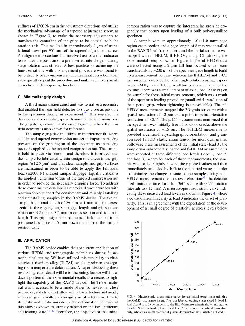
A sample with an approximately 1.0 × 1.0 mm2 gageregion cross section and a gage length of 8 mm was installedin the RAMS load frame insert, and the initial structure wasmapped with nf-HEDM, ff-HEDM, and µ-CT utilizing theexperimental setup shown in Figure 1. The nf-HEDM datawere collected using a 2 µm tall line-focused x-ray beamtranslated along∼200 µm of the specimen gage length to buildup a measurement volume, whereas the ff-HEDM and µ-CTmeasurements were collected in single rotations using, respec-tively, a 600 µm and 1000 µm tall box beam which defined thevolume. There was a small amount of axial load (23 MPa) onthe sample for these initial measurements, which was a resultof the specimen loading procedure (small axial translation ofthe tapered grips when tightening is unavoidable). The nf-HEDM measurements mapped the 3D grain structure with aspatial resolution of ∼2 µm and a point-to-point orientationresolution of <0.1◦. The µ-CT measurements confirmed thatthe specimen was initially free of voids or cracks above thespatial resolution of ∼1.5 µm. The ff-HEDM measurementsprovided a centroid, crystallographic orientation, and grain-averaged full 3D elastic strain tensor for individual grains.Following these measurements of the initial state (load 0), thesample was subsequently loaded and ff-HEDM measurementswere repeated at three different load levels (load 1, load 2,and load 3), where for each of these measurements, the sam-ple was loaded slightly beyond the reported values and thenimmediately unloaded by 10% to the reported values in orderto minimize the change in state of the sample during a ff-HEDM measurement due to stress relaxation50 (the detectorused limits the time for a full 360◦ scan with 0.25◦ rotationintervals to ∼12 min). A macroscopic stress-strain curve indi-cating these measured load levels is shown in Figure 4, wherea deviation from linearity at load 3 indicates the onset of plas-ticity. This is in agreement with the expectation of the devel-opment of a small degree of plasticity at stress levels below
FIG. 4. Macroscopic stress-strain curve for an initial experiment utilizingthe RAMS load frame insert. The four labeled loading states (load 0, load 1,load 2, and load 3) correspond to the HEDM measurements shown in Figures5 and 6. Note that load 0, load 1, and load 2 correspond to elastic deformationonly, whereas a small amount of plastic deformation has initiated at Load 3.
5 Distribution A. Approved for public release (PA): distribution unlimited.
093902-6 Shade et al. Rev. Sci. Instrum. 86, 093902 (2015)
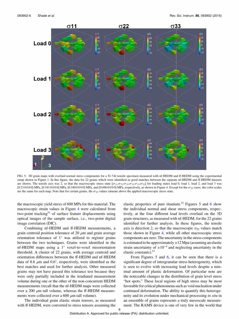
FIG. 5. 3D grain maps with overlaid normal stress components for a Ti-7Al tensile specimen measured with nf-HEDM and ff-HEDM using the experimentalsetup shown in Figure 1. In this figure, the data for 22 grains which were identified as good matches between the separate nf-HEDM and ff-HEDM datasetsare shown. The tensile axis was 2, so that the macroscopic stress state [σ11σ22σ33σ12σ13σ23] for loading states load 0, load 1, load 2, and load 3 was[0 23 0 0 0 0] MPa, [0 181 0 0 0 0] MPa, [0 340 0 0 0 0] MPa, and [0 496 0 0 0 0] MPa, respectively, as shown in Figure 4. Except for the σ22 cases, the color scalesare the same for each map. Note that for certain grains, the σ22 values saturate above the applied macroscopic stress state.
the macroscopic yield stress of 600 MPa for this material. Themacroscopic strain values in Figure 4 were calculated fromtwo-point tracking51 of surface feature displacements usingoptical images of the sample surface, i.e., two-point digitalimage correlation (DIC).
Combining nf-HEDM and ff-HEDM measurements, agrain centroid position tolerance of 20 µm and grain averageorientation tolerance of 1◦ was utilized to register grainsbetween the two techniques. Grains were identified in thenf-HEDM maps using a 1◦ voxel-to-voxel misorientationthreshold. A cluster of 22 grains, with average centroid andorientation differences between the ff-HEDM and nf-HEDMdata of 8.6 µm and 0.6◦, respectively, were identified as thebest matches and used for further analysis. Other measuredgrains may not have passed this tolerance test because theywere only partially included in the irradiated measurementvolume during one or the other of the non-concurrent HEDMmeasurements (recall that the nf-HEDM maps were collectedover a 200 µm tall volume, whereas the ff-HEDM measure-ments were collected over a 600 µm tall volume).
The individual grain elastic strain tensors, as measuredwith ff-HEDM, were converted to stress tensors assuming the
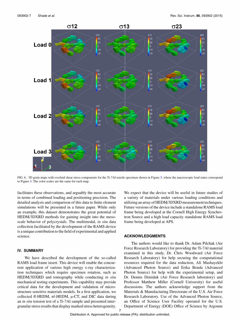
elastic properties of pure titanium.52 Figures 5 and 6 showthe individual normal and shear stress components, respec-tively, at the four different load levels overlaid on the 3Dgrain structures, as measured with nf-HEDM, for the 22 grainsidentified for further analysis. In these figures, the tensileaxis is direction 2, so that the macroscopic σ22 values matchthose shown in Figure 4, while all other macroscopic stresscomponents are zero. The uncertainty in the stress componentsis estimated to be approximately±12 Mpa (assuming an elasticstrain uncertainty of ±10−4 and neglecting uncertainty in theelastic constants).53
From Figures 5 and 6, it can be seen that there is asignificant degree of intergranular stress heterogeneity, whichis seen to evolve with increasing load levels despite a min-imal amount of plastic deformation. Of particular note arethe noticeable changes in the distribution of grain level stress“hot spots.” These local regions of high stress may be mostfavorable for critical phenomena such as void nucleation undercontinued deformation. The ability to quantify this heteroge-neity and its evolution under mechanical processing in situ inan ensemble of grains represents a truly mesoscale measure-ment. The RAMS device is one of very few in the world that
6 Distribution A. Approved for public release (PA): distribution unlimited.
093902-7 Shade et al. Rev. Sci. Instrum. 86, 093902 (2015)
FIG. 6. 3D grain maps with overlaid shear stress components for the Ti-7Al tensile specimen shown in Figure 5, where the macroscopic load states correspondto Figure 4. The color scales are the same for each map.
facilitates these observations, and arguably the most accuratein terms of combined loading and positioning precision. Thedetailed analysis and comparison of this data to finite elementsimulations will be presented in a future paper. While onlyan example, this dataset demonstrates the great potential ofHEDM/3DXRD methods for gaining insight into the meso-scale behavior of polycrystals. The multimodal, in situ datacollection facilitated by the development of the RAMS deviceis a unique contribution to the field of experimental and appliedscience.
IV. SUMMARY
We have described the development of the so-calledRAMS load frame insert. This device will enable the concur-rent application of various high energy x-ray characteriza-tion techniques which require specimen rotation, such asHEDM/3DXRD and tomography while conducting in situmechanical testing experiments. This capability may providecritical data for the development and validation of micro-structure sensitive materials models. In a first application, wecollected ff-HEDM, nf-HEDM, µ-CT, and DIC data duringan in situ tension test of a Ti-7Al sample and presented inter-granular stress results that display marked stress heterogeneity.
We expect that the device will be useful in future studies ofa variety of materials under various loading conditions andutilizing an array of HEDM/3DXRD measurement techniques.Future versions of the device include a standalone RAMS loadframe being developed at the Cornell High Energy Synchro-tron Source and a high load capacity standalone RAMS loadframe being developed at APS.
ACKNOWLEDGMENTS
The authors would like to thank Dr. Adam Pilchak (AirForce Research Laboratory) for providing the Ti-7Al materialexamined in this study, Dr. Chris Woodward (Air ForceResearch Laboratory) for help securing the computationalresources required for the data reduction, Ali Mashayekhi(Advanced Photon Source) and Erika Benda (AdvancedPhoton Source) for help with the experimental setup, andDr. Dennis Dimiduk (Air Force Research laboratory) andProfessor Matthew Miller (Cornell University) for usefuldiscussions. The authors acknowledge support from theMaterials & Manufacturing Directorate of the U.S. Air ForceResearch Laboratory. Use of the Advanced Photon Source,an Office of Science User Facility operated for the U.S.Department of Energy (DOE) Office of Science by Argonne
7 Distribution A. Approved for public release (PA): distribution unlimited.
093902-8 Shade et al. Rev. Sci. Instrum. 86, 093902 (2015)
National Laboratory was supported by the U.S. DOE underContract No. DEAC02-06CH11357.
1P. R. Dawson, Int. J. Solids Struct. 37, 115 (2000).2F. Roters, P. Eisenlohr, L. Hantcherli, D. D. Tjahjanto, T. R. Bieler, and D.Raabe, Acta Mater. 58, 1152 (2010).
3D. L. McDowell, J. H. Panchal, H. J. Choi, C. C. Seepersad, J. K. Allen, andF. Mistree, Integrated Design of Multiscale, Multifunctional Materials andProducts (Butterworth-Heinemann, Burlington, MA, 2010).
4Computational Methods for Microstructure-Property Relationships, editedby S. Ghosh and D. Dimiduk (Springer, New York, 2011).
5R. Pokharel, J. Lind, A. K. Kanjarla, R. A. Lebensohn, S. F. Li, P. Kenesei,R. M. Suter, and A. D. Rollett, Annu. Rev. Condens. Matter Phys. 5, 317(2014).
6J. C. Schuren, P. A. Shade, J. V. Bernier, S. F. Li, B. Blank, J. Lind, P. Kenesei,U. Lienert, R. M. Suter, T. J. Turner, D. M. Dimiduk, and J. Almer, Curr.Opin. Solid State Mater. Sci. 19, 235 (2015).
7G. Winther, L. Margulies, S. Schmidt, and H. F. Poulsen, Acta Mater. 52,2863 (2004).
8S. R. Kalidindi, A. Bhattacharyya, and R. D. Doherty, Proc. R. Soc. A 460,1935 (2004).
9A. Musienko, A. Tatschl, K. Schmidegg, O. Kolednik, R. Pippan, and G.Cailletaud, Acta Mater. 55, 4121 (2007).
10E. Heripre, M. Dexet, J. Crepin, L. Gelebart, A. Roos, M. Bornert, and D.Caldemaison, Int. J. Plast. 23, 1512 (2007).
11Z. Zhao, M. Ramesh, D. Raabe, A. M. Cuitino, and R. Radovitzky, Int. J.Plast. 24, 2278 (2008).
12L. St-Pierre, E. Heripre, M. Dexet, J. Crepin, G. Bertolino, and N. Bilger,Int. J. Plast. 24, 1516 (2008).
13A. J. Beaudoin, M. Obstalecki, R. Storer, W. Tayon, J. Mach, P. Kenesei,and U. Lienert, Modell. Simul. Mater. Sci. Eng. 20, 024006 (2012).
14P. A. Shade, M. A. Groeber, J. C. Schuren, and M. D. Uchic, Integr. Mater.Manuf. Innov. 2, 5 (2013).
15T. J. Turner, P. A. Shade, J. C. Schuren, and M. A. Groeber, Modell. Simul.Mater. Sci. Eng. 21, 015002 (2013).
16H. Lim, J. D. Carroll, C. C. Battaile, T. E. Bucheit, B. L. Boyce, and C. R.Weinberger, Int. J. Plast. 60, 1 (2014).
17C. C. Tasan, M. Diehl, D. Yan, C. Zambaldi, P. Shanthraj, F. Roters, and D.Raabe, Acta Mater. 81, 386 (2014).
18M. P. Miller and P. R. Dawson, Curr. Opin. Solid State Mater. Sci. 18, 286(2014).
19C. Zhang, H. Li, P. Eisenlohr, W. Liu, C. J. Boehlert, M. A. Crimp, and T.R. Bieler, Int. J. Plast. 69, 21 (2015).
20H. Abdolvand, M. Majkut, J. Oddershede, S. Schmidt, U. Lienert, B. J. Diak,P. J. Withers, and M. R. Daymond, Int. J. Plast. 70, 77 (2015).
21H. F. Poulsen, Three-Dimensional X-Ray Diffraction Microscopy: MappingPolycrystals and their Dynamics (Springer, Berlin, 2004).
22U. Lienert, S. F. Li, C. M. Hefferan, J. Lind, R. M. Suter, J. V. Bernier, N.R. Barton, M. C. Brandes, M. J. Mills, M. P. Miller, B. Jakobsen, and W.Pantleon, JOM 63, 70 (2011).
23H. F. Poulsen, J. Appl. Crystallogr. 45, 1084 (2012).24H. F. Poulsen, S. F. Nielsen, E. M. Lauridsen, S. Schmidt, R. M. Suter, U.
Lienert, L. Margulies, T. Lorentzen, and D. J. Jensen, J. Appl. Crystallogr.34, 751 (2001).
25L. Margulies, T. Lorentzen, H. F. Poulsen, and T. Leffers, Acta Mater. 50,1771 (2002).
26J. Oddershede, S. Schmidt, H. F. Poulsen, H. O. Sorensen, J. Wright, and W.Reimers, J. Appl. Crystallogr. 43, 539 (2010).
27J. V. Bernier, N. R. Barton, U. Lienert, and M. P. Miller, J. Strain Anal. Eng.Des. 46, 527 (2011).
28R. M. Suter, D. Hennessy, C. Xiao, and U. Lienert, Rev. Sci. Instrum. 77,123905 (2006).
29S. F. Li and R. M. Suter, J. Appl. Crystallogr. 46, 512 (2013).30P. J. Withers and M. Preuss, Annu. Rev. Mater. Res. 42, 81 (2012).31B. E. Blank, J. Schuren, P. Shade, and T. Turner, U.S. patent application
14/461,582 (18 August 2014).32T. M. Breunig, S. R. Stock, and R. C. Brown, Mater. Eval. 51, 596
(1993).33H. G. Brokmeier, U. Zink, T. Reinert, and W. Murach, J. Appl. Crystallogr.
29, 501 (1996).34J. C. Schuren, M. P. Miller, and A. Kazimirov, Exp. Mech. 52, 461
(2012).35H. A. Bale, A. Haboub, A. A. MacDowell, J. R. Nasiatka, D. Y. Parkin-
son, B. N. Cox, D. B. Marshall, and R. O. Ritchie, Nat. Mater. 12, 40(2013).
36S. F. Li, J. Lind, C. M. Hefferan, R. Pokharel, U. Lienert, A. D. Rollett, andR. M. Suter, J. Appl. Crystallogr. 45, 1098 (2012).
37J. Lind, S. F. Li, R. Pokharel, U. Lienert, A. D. Rollett, and R. M. Suter, ActaMater. 76, 213 (2014).
38H. M. Reiche, S. C. Vogel, P. Mosbrucker, E. J. Larson, and M. R. Daymond,Rev. Sci. Instrum. 83, 053901 (2012).
39M. Hoelzel, W. M. Gan, M. Hofmann, C. Randau, G. Seidl, Ph. Juttner,and W. W. Schmahl, Nucl. Instrum. Methods Phys. Res., Sect. A 711, 101(2013).
40P. Wyss, P. Thurner, R. Bronnimann, U. Sennhauser, M. Stampanoni, R.Abela, and R. Muller, Rev. Sci. Instrum. 76, 076106 (2005).
41W. Xu, K. Lauer, Y. Chu, and E. Nazaretski, J. Synchrotron Radiat. 21, 1367(2014).
42H. Sharma, R. M. Huizenga, and S. E. Offerman, J. Appl. Crystallogr. 45,705 (2012).
43D. H. Lassila, M. M. LeBlanc, and G. J. Kay, J. Eng. Mater. Technol. 124,290 (2002).
44P. A. Shade, R. Wheeler, Y. S. Choi, M. D. Uchic, D. M. Dimiduk, and H.L. Fraser, Acta Mater. 57, 4580 (2009).
45R. V. Jones and I. R. Young, J. Sci. Instrum. 33, 11 (1956).46C. Wenjie, L. Wei, and Y. Guilin, in 11th International Conference on
Control Automation Robotics Vision (IEEE, 2010), p. 1755.47U. Lienert, M. C. Brandes, J. V. Bernier, J. Weiss, S. D. Shastri, M. J. Mills,
and M. P. Miller, Mater. Sci. Eng. A 524, 46 (2009).48M. C. Brandes, M. J. Mills, and J. C. Williams, Metall. Mater. Trans. A 41,
3463 (2010).49J. Kwon, M. C. Brandes, P. Sudharshan Phani, A. P. Pilchak, Y. F. Gao, E.
P. George, G. M. Pharr, and M. J. Mills, Acta Mater. 61, 4743 (2013).50P. Dawson, D. Boyce, S. MacEwen, and R. Rogge, Metall. Mater. Trans. A
31, 1543 (2000).51M. Guizar-Sicairos, S. T. Thurman, and J. R. Fienup, Opt. Lett. 33, 156
(2008).52E. S. Fisher and C. J. Renkin, Phys. Rev. 135, 482 (1964).53J. C. Schuren and M. P. Miller, J. Strain Anal. Eng. Des. 46, 663 (2011).
8 Distribution A. Approved for public release (PA): distribution unlimited.

Review of Scientific Instruments is copyrighted by AIP Publishing LLC (AIP). Reuse of AIPcontent is subject to the terms at: http://scitation.aip.org/termsconditions. For moreinformation, see http://publishing.aip.org/authors/rights-and-permissions.
9 Distribution A. Approved for public release (PA): distribution unlimited.