Embed Size (px)
Citation preview

SOLIDWORKS 15 SHAFT SPINNER PAgE 3-1
Spinner
Shaft A. Revolve1.Step 1. Click File Menu > New, click Part and OK.
Step 2. Click Front Plane in the Feature Manager and click Sketch from the Context toolbar, Fig. 1.
Step 3. Click Line (L) on the Sketch toolbar.
Step 4. Starting from Origin draw the two sets of lines, Fig. 2. To terminate chain, double click back on the line you have just drawn.
Step 5. Click 3 Point Arc (S) in the Arc flyout on the Sketch toolbar.
Step 6. Draw 2 arcs between endpoints of lines, Fig. 3.
Step 7. Right click graphics area and click Select from menu to unselect 3 Point Arc tool.
Step 8. Ctrl click both arcs to select both. Release Ctrl key and
click Make Tangent on the Context toolbar, Fig. 4.
Step 9. Click Centerline in the Line flyout on the Sketch toolbar.
Step 10. Draw centerline up from Origin , Fig. 5.
Chapter 3
12/8/14
Fig. 1
Fig. 2
Origin
Fig. 3
Fig. 5Fig. 4
Origin
Ctrl click both arcs
© Cudacountry.net Tech Edhttp://www.cudacountry.net email:[email protected]

SOLIDWORKS 15 SHAFT SPINNER PAgE 3-2
Step 11. Click Smart Dimension
(S) on the Sketch toolbar.
Step 12. Add dimensions, Fig. 6. Dimension double dis-tance diameter to endpoint of angled line. To double distance dimension, click vertical centerline and then bottom endpoint of line, move the cursor to left of the centerline (Origin) and click. Key-in .782 dimension and press ENTER. Add other dimensions. To dimension to the arc edge, hold down the Shift key before clicking the arc.
Step 13. Click Features on the Command Manager toolbar.
Step 14. Click Revolved Boss/Base on the Features toolbar.
Step 15. In the Revolve Property Manger:
click OK .
B. Save as "SHAFT".Step 1. Click File Menu > Save As.
Step 2. Key-in SHAFT for the filename and press EN-TER.
Fig. 6
Fig. 7
Fig. 8

SOLIDWORKS 15 SHAFT SPINNER PAgE 3-3
C. Insert Part - Base.Step 1. Click Insert Menu > Part.
Step 2. Select your Base part and open.
Step 3. In the Insert Part Property Manager, Fig. 9
click OK .
Step 4. In the Locate Part Property Manager: under Translate, Fig. 10
Delta Y -.3 press Tab key on keyboard, Fig. 11
click OK .
D. Indent.Step 1. Click Insert Menu > Features > Indent.
Step 2. In the Indent Property Manager: under Selections, Fig. 11 Target body: click Revolved1 (Shaft), Fig. 12 Tool body region: click a face on Base check Cut
under Parameters Clearance .02
click OK .
Step 3. Hide Base. To hide, click Base and Hide on the Context toolbar, Fig. 14.
Fig. 13
Fig. 9
Fig. 10
Fig. 11
Fig. 10
Fig. 12Fig. 14
Tool body
Target body

SOLIDWORKS 15 SHAFT SPINNER PAgE 3-4
E. Chamfer1.
Step 1. Click Chamfer in the Fillet flyout on the Features toolbar.
Step 2. In the Chamfer Property Manager set: under Chamfer Parameters, Fig. 15
Depth .08
Angle 45º select Full preview click top edge of center shaft, Fig. 16 click OK .
F. Revolved Cut.Step 1. Click Front Plane in the Feature
Manager and click Sketch from the Context toolbar, Fig. 18.
Step 2. Click Normal To on the Stan-dard Views toolbar. (Ctrl-8)
Step 3. Click Wireframe on the View toolbar.
Step 4. Click Line (L) on the Sketch toolbar.
Step 5. Draw right triangle with the horizontal line coincident with the top edge of the Revolve, Fig. 19.
Keep away from Origin .
Fig. 15
Fig. 18
Fig. 19
Fig. 16
Edge
Fig. 17
Origin

SOLIDWORKS 15 SHAFT SPINNER PAgE 3-5
Step 6. Click Centerline in the Line flyout on the Sketch toolbar.
Step 7. Draw vertical centerline up from
Origin , Fig. 20.
Step 8. Click Smart Dimension (S) on the Sketch toolbar.
Step 9. Add dimensions, Fig. 21.
Step 10. Right click graphics area and click Select from menu to unselect Smart Dimension.
Step 11. Ctrl click the vertical line and right silhouette edge of center shaft to select both, Fig. 22 and Fig. 23. Release Ctrl key and click Make Collinear on the Context toolbar.
Step 12. Click Shaded With Edges on the View toolbar.
Step 13. Click Features on the Command Manager toolbar.
Step 14. Click Revolved Cut on the Features toolbar.
Step 15. In the Cut-Revolve Property Manager:
click OK .
Step 16. Save. Use Ctrl-S.
Fig. 25Fig. 24
Fig. 20
Fig. 21
Fig. 22
Fig. 23
Origin
Ctrl click line
and edge
Fig. 26

SOLIDWORKS 15 SHAFT SPINNER PAgE 3-6
G. Move Face.Step 1. Click Insert Menu > Face > Move.
Step 2. In the Move Face Property Manager: under Move Face, Fig. 27 select Translate click top and chamfer faces of center shaft, Fig. 28 under Parameters
Delta Y .25 press Tab key on keyboard click OK .
H. Fillet1 and 2.
Step 1. Click Fillet on the Features toolbar.
Step 2. In the Fillet Property Manager: select FilletXpert, Fig. 29
Radius .03 click chamfer face, Fig. 30 and 4 faces inside 2 of the 4 are selected, Fig. 31 use down arrow on keyboard to rotate view and select the other 2, Fig. 32 click Apply, Fig. 29 and Fig. 33.
Fig. 27 Fig. 28
Fig. 29
Fig. 30
Fig. 31
Fig. 32 Fig. 33

SOLIDWORKS 15 SHAFT SPINNER PAgE 3-7
Step 3. Click Trimetric on the Stan-dard Views toolbar.
Step 4. In the Fillet Property Manager:
set Radius .08, Fig. 34 click top outside cylindrical face of rim, Fig. 35click OK .
Step 5. Save. Use Ctrl-S.
I. Revolve2.Step 1. Click Front Plane in the Fea-
ture Manager and click Sketch from the Context toolbar, Fig. 37.
Step 2. Click Normal To on the Standard Views toolbar. (Ctrl-8)
Step 3. Use Z key on keyboard to zoom out.
Step 4. Click Wireframe on the View toolbar.
Step 5. Click Line (L) on the Sketch toolbar.
Step 6. Start at Midpoint of edge inside bottom of base. Draw all the line shown in, Fig. 38.
Step 7. Right click graphics area and click Select from menu to unselect Line tool.
Step 8. Ctrl click the Line 1 and Line 2 to select both.
Fig. 35
Fig. 34
Fig. 37
Fig. 36
Fig. 38

SOLIDWORKS 15 SHAFT SPINNER PAgE 3-8
Release Ctrl key and click Make Collinear
on the Context toolbar, Fig. 39.
Step 9. Click Centerline in the Line flyout
on the Sketch toolbar.
Step 10. Draw centerline down from bottom left corner, Fig. 40.
Step 11. Click Smart Dimension (S) on the Sketch toolbar.
Step 12. Add dimensions, Fig. 41.
Step 13. Click Shaded With Edges on the View toolbar.
Step 14. Click Features on the Command Manager toolbar.
Step 15. Click Revolved Boss/Base on the Features toolbar.
Step 16. In the Revolve Property Manger: under Direction1, Fig. 42 uncheck Merge results
click OK .
Fig. 41
Fig. 42
Fig. 43
Fig. 30Fig. 39
Ctrl click lines
Fig. 44

SOLIDWORKS 15 SHAFT SPINNER PAgE 3-9
J. Chamfer2.
Step 1. Click Chamfer in the Fillet flyout on the Features toolbar.
Step 2. In the Chamfer Property Manager set: under Chamfer Parameters, Fig. 45
Depth .1
Angle 45º select Full preview click edges of center shaft, Fig. 46 click OK .
K. Fillet3.
Step 1. Click Fillet on the Features toolbar.
Step 2. In the Fillet Property Manager: select FilletXpert, Fig. 48
Radius .08 click chamfer faces of center shaft, Fig. 49click OK .
Step 3. Save. Use Ctrl-S.
Fig. 45 Fig. 46
Fig. 48
Fig. 47
Fig. 49 Fig. 50

SOLIDWORKS 15 SHAFT SPINNER PAgE 3-10
L. Shell.Step 1. Use up arrow and keyboard to rotate view to view bottom face, Fig. 52.
Step 2. Click Shell on the Features toolbar.
Step 3. In the Shell Property Manager set: under Parameters, Fig. 51
Distance .08 check Show preview in the face to remove box and click bottom face, Fig. 52 click OK .
Step 4. Save. Use Ctrl-S.
M. Combine Bodies.Step 1. Click Insert Menu > Features > Combine.
Step 2. In the Combine Property Manager: under Operation Type, Fig. 54 select Add click both bodies, Fig. 55 click OK .
Fig. 51
Fig. 52 Fig. 53
Fig. 54
Fig. 55Fig. 53

SOLIDWORKS 15 SHAFT SPINNER PAgE 3-11
N. Fillet4 Full Round Under Rim.
Step 1. Click Fillet on the Features toolbar.
Step 2. In the Fillet Property Manager: select Manual, Fig. 56 under Fillet Type
select Full Round Fillet add a Full Round Fillet to fillet face at bottom Revolve1, bottom face of Revolve1 and cylindrical face Revolve2, Fig. 57 and Fig. 58. After selecting a surface, right click to move selection to next selection box click OK .
O. Create Plane1.Step 1. Click Trimetric on the Stan-
dard Views toolbar.
Step 2. Click Top Plane in the Feature Manager to display plane in graphics area, Fig. 59.
Step 3. Ctrl drag Top plane down in graphics area and release, Fig. 60.
Step 4. In the Plane Property Manager set: under First Reference, Fig. 61
Distance 1.3 and press ENTER the new plane should be below Top plane, Fig. 60, if in wrong direction, uncheck Flip offset click OK .
Fig. 56Fig. 57
Fig. 58
Fig. 59
Fig. 61Fig. 60
Hold down Ctrl drag plane
Drag plane down

SOLIDWORKS 15 SHAFT SPINNER PAgE 3-12
P. Extrude Boss.Step 1. Hide Plane1 . To hide, click Plane1 in the
Feature Manager and Hide on the Context toolbar, Fig. 62.
Step 2. Click Plane1 in the Feature Manager and click Sketch from the Context toolbar, Fig. 63.
Step 3. Click Offset Entities on the Sketch toolbar.
Step 4. In the Convert Entities Property Manager: under Entities to Convert, Fig. 64 click edge of long cylindrical face of Revolve2 at fillet, Fig. 65 click OK twice.
Step 5. Hide Fillet4 solid body (shaft). To hide, expand Solid Bodies folder in the Feature Manager. In the Display Pane under Hide/Show column for
Fillet4 click Show to turn off show, Fig. 67.
Fig. 63Fig. 62
Fig. 64
Fig. 65
Fig. 67
Fig. 66

SOLIDWORKS 15 SHAFT SPINNER PAgE 3-13
Step 6. Click Normal To on the Stan-dard Views toolbar. (Ctrl-8)
Step 7. Click Line (L) on the Sketch toolbar.
Step 8. Draw 3 perpendicular lines using the automatic perpendicular rela-tion, cursor will change to yellow perpendicular icon as you draw, Fig. 68.
Step 9. Click Centerline in the Line
flyout on the Sketch toolbar.
Step 10. Draw horizontal centerline from
Origin to right out to the converted circle, Fig. 69. And a vertical centerline down from Ori-
gin but short of the converted circle.
Step 11. Click Smart Dimension (S) on the Sketch toolbar.
Step 12. Add dimensions, Fig. 70.
Step 13. Click Tangent Arc in the Arc
flyout on the Sketch toolbar.
Step 14. Draw tangent arc between end-points of bottom line and endpoint of horizontal centerline. Draw sec-ond tangent arc between endpoints of top line and converted circle,Fig. 71.
Fig. 68
Fig. 69
Fig. 70
Fig. 71

SOLIDWORKS 15 SHAFT SPINNER PAgE 3-14
Step 15. Click Smart Dimension (S) on the Sketch toolbar.
Step 16. Dimension arc radiuses, Fig. 72.
Step 17. Right click graphics area and click Select from menu to unselect Tangent Arc tool.
Step 18. Ctrl click converted circle and an arc to select both. Release Ctrl key
and click Make Tangent on the Context toolbar, Fig. 73.
Step 19. Ctrl click converted circle and other arc to select both. Release Ctrl key
and click Make Tangent on the Context toolbar, Fig. 74.
Fig. 72
Fig. 73
Fig. 74
Ctrl click arc and
convert circle
Ctrl click arc and
convert circle

SOLIDWORKS 15 SHAFT SPINNER PAgE 3-15
Step 20. Click Trim Entities (S) on the Sketch toolbar.
Step 21. In the Trim Property Manger select Power Trim , Fig. 75. Trim away converted circle between arcs Drag across converted circle to trim, Fig. 76. Results shown in Fig. 77. Click OK when done.
Step 22. Click Trimetric on the Standard Views toolbar.
Step 23. Show Fillet4 solid body (shaft), Fig. 78. To show, expand Solid Bodies folder in the Feature Manager. In the Dis-play Pane under Hide/Show column for Fillet4 click Hide
to turn hide off.
Step 24. Click Features on the Command Manager toolbar.
Fig. 77Fig. 76
Fig. 75
Fig. 78
Drag across

SOLIDWORKS 15 SHAFT SPINNER PAgE 3-16
Step 25. Click Extruded Boss/Base on the Features toolbar.
Step 26. In the Property Manager set: under Direction 1, Fig. 79
Depth .08 click Reverse
direction Direction arrow should point down, Fig. 80
click OK .
Q. Draft.Step 1. Click Draft on the Features toolbar.
Step 2. In the Draft Property Manager set: under Type of Draft, Fig. 82 select Neutral plane under Draft Angle
Angle 10º
under Neutral Plane click vertical face of extrude, Fig. 83 under Faces to Draft click top and bottom faces of extrude, Fig. 83 and Fig. 84. Use up arrow and keyboard to rotate view. Click OK .
Step 3. Save. Use Ctrl-S.
Fig. 79 Fig. 81Fig. 80
Direction arrow
Fig. 82
Fig. 83
Fig. 84
Fig. 85
Draft face 1
Neutral plane
Draft face 2
SOLIDWORKS 15 SHAFT SPINNER PAgE 3-17
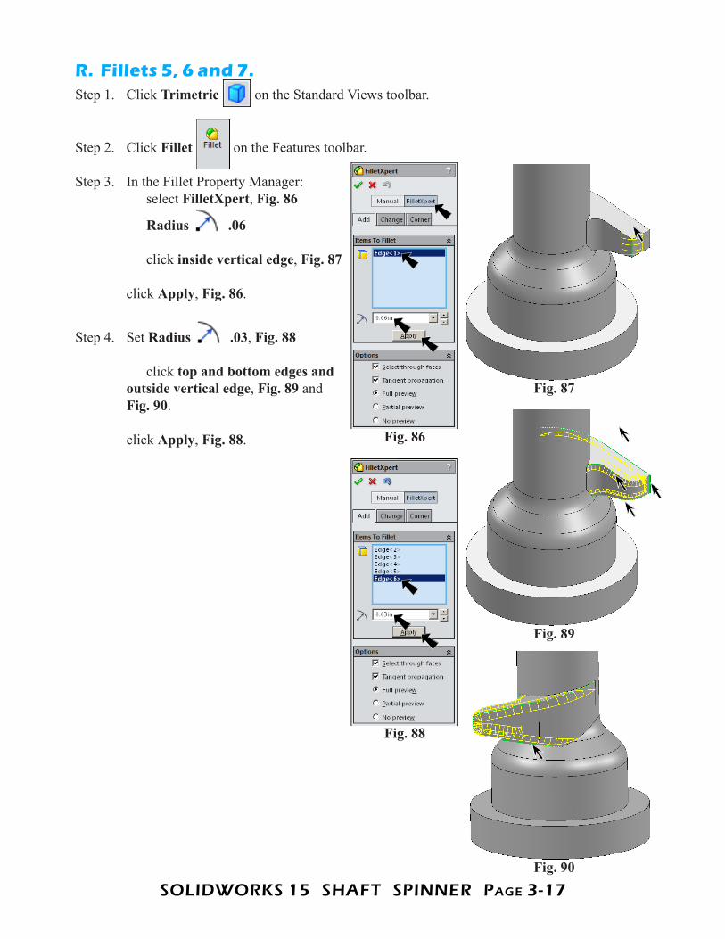
R. Fillets 5, 6 and 7.Step 1. Click Trimetric on the Standard Views toolbar.
Step 2. Click Fillet on the Features toolbar.
Step 3. In the Fillet Property Manager: select FilletXpert, Fig. 86
Radius .06 click inside vertical edge, Fig. 87 click Apply, Fig. 86.
Step 4. Set Radius .03, Fig. 88 click top and bottom edges and outside vertical edge, Fig. 89 and Fig. 90.
click Apply, Fig. 88. Fig. 86
Fig. 87
Fig. 89
Fig. 88
Fig. 90

SOLIDWORKS 15 SHAFT SPINNER PAgE 3-18
Step 5. Set Radius .04, Fig. 91 click edges at shaft, Fig. 92 click OK .
S. Circular Pattern.Step 1. Shift click Boss-Extrude1 and last
Fillet to select the features, Fig. 94. To Shift click, hold down the Shift key, click first feature, Boss-Extrude1 and click last feature, last Fillet.
Step 2. Click Circular Pattern on the Features
toolbar.
Step 3. In the Circular Pattern Property Manager set: under Parameters, Fig. 95 in the Pattern Axis box click cylindrical face of shaft, Fig. 96
Number of Instances 2 check Equal spacing under Features to Pattern features are selected click OK .
Fig. 91
Fig. 92
Fig. 95
Fig. 96
Fig. 94
Fig. 97
Axis
Fig. 93

SOLIDWORKS 15 SHAFT SPINNER PAgE 3-19
T. Appearance Color.Step 1. Click the Propeller, click Appearance Callout on the Context
toolbar and click PROPELLER , Fig. 98.
Step 2. In the Appearances Property Manager under Color, Fig. 99 set RGB values R 201 G 255 B 94 click OK .
Step 3. Save. Use Ctrl-S.
Fig. 99
Fig. 98
Fig. 100


![50000865[1] spinner 6600](https://img.pdfslide.us/doc/110x75/55cf98fa550346d0339acda4/500008651-spinner-6600.jpg)