Embed Size (px)
Citation preview
A review on thermoelectric renewable energy: Principle parametersthat affect their performance
Mohamed Hamid Elsheikh a,c,n, Dhafer Abdulameer Shnawah a, Mohd Faizul Mohd Sabri a,Suhana Binti Mohd Said b, Masjuki Haji Hassan a, Mohamed Bashir Ali Bashir a,Mahazani Mohamad b
a Department of Mechanical Engineering, University of Malaya, 50603 Kuala Lumpur, Malaysiab Department of Electrical Engineering, University of Malaya, 50603 Kuala Lumpur, Malaysiac Department of Mechanical Engineering, University of Bahri,13104 Khartoum, Sudan
a r t i c l e i n f o
Article history:Received 17 June 2013Received in revised form1 October 2013Accepted 19 October 2013Available online 12 November 2013
Keywords:Thermoelectric materialsFigure of meritPerformance challenge
a b s t r a c t
Developing thermoelectric materials with superior performance means tailoring interrelated thermo-electric physical parameters – electrical conductivities, Seebeck coefficients, and thermal conductivities –for a crystalline system. High electrical conductivity, low thermal conductivity, and a high Seebeckcoefficient are desirable for thermoelectric materials. Therefore, knowledge of the relation betweenelectrical conductivity and thermal conductivity is essential to improve thermoelectric properties. Ingeneral, research in recent years has focused on developing thermoelectric structures and materials ofhigh efficiency. The importance of this parameter is universally recognized; it is an established,ubiquitous, routinely used tool for material, device, equipment and process characterization both inthe thermoelectric industry and in research. In this paper, basic knowledge of thermoelectric materialsand an overview of parameters that affect the figure of merit ZT are provided. The prospects for theoptimization of thermoelectric materials and their applications are also discussed.
& 2013 Elsevier Ltd. All rights reserved.
Contents
1. Introduction . . . . . . . . . . . . . . . . . . . . . . . . . . . . . . . . . . . . . . . . . . . . . . . . . . . . . . . . . . . . . . . . . . . . . . . . . . . . . . . . . . . . . . . . . . . . . . . . . . . . . . . . 3382. Thermoelectric properties . . . . . . . . . . . . . . . . . . . . . . . . . . . . . . . . . . . . . . . . . . . . . . . . . . . . . . . . . . . . . . . . . . . . . . . . . . . . . . . . . . . . . . . . . . . . . 338
2.1. The Seebeck coefficient . . . . . . . . . . . . . . . . . . . . . . . . . . . . . . . . . . . . . . . . . . . . . . . . . . . . . . . . . . . . . . . . . . . . . . . . . . . . . . . . . . . . . . . . . 3392.2. Thermal conductivity. . . . . . . . . . . . . . . . . . . . . . . . . . . . . . . . . . . . . . . . . . . . . . . . . . . . . . . . . . . . . . . . . . . . . . . . . . . . . . . . . . . . . . . . . . . 3402.3. Electrical resistivity (ρ) . . . . . . . . . . . . . . . . . . . . . . . . . . . . . . . . . . . . . . . . . . . . . . . . . . . . . . . . . . . . . . . . . . . . . . . . . . . . . . . . . . . . . . . . . 340
3. Categories of TE material . . . . . . . . . . . . . . . . . . . . . . . . . . . . . . . . . . . . . . . . . . . . . . . . . . . . . . . . . . . . . . . . . . . . . . . . . . . . . . . . . . . . . . . . . . . . . 3403.1. Metal-based thermoelectrics . . . . . . . . . . . . . . . . . . . . . . . . . . . . . . . . . . . . . . . . . . . . . . . . . . . . . . . . . . . . . . . . . . . . . . . . . . . . . . . . . . . . . 3413.2. Ceramics. . . . . . . . . . . . . . . . . . . . . . . . . . . . . . . . . . . . . . . . . . . . . . . . . . . . . . . . . . . . . . . . . . . . . . . . . . . . . . . . . . . . . . . . . . . . . . . . . . . . . 3423.3. Polymers . . . . . . . . . . . . . . . . . . . . . . . . . . . . . . . . . . . . . . . . . . . . . . . . . . . . . . . . . . . . . . . . . . . . . . . . . . . . . . . . . . . . . . . . . . . . . . . . . . . . 3423.4. Semiconductors . . . . . . . . . . . . . . . . . . . . . . . . . . . . . . . . . . . . . . . . . . . . . . . . . . . . . . . . . . . . . . . . . . . . . . . . . . . . . . . . . . . . . . . . . . . . . . . 343
4. Governing parameters for thermoelectric material selection: intrinsic material properties . . . . . . . . . . . . . . . . . . . . . . . . . . . . . . . . . . . . . . . . . 3434.1. Energy gap and band structure in semiconductors . . . . . . . . . . . . . . . . . . . . . . . . . . . . . . . . . . . . . . . . . . . . . . . . . . . . . . . . . . . . . . . . . . . 3434.2. Charge carrier concentration. . . . . . . . . . . . . . . . . . . . . . . . . . . . . . . . . . . . . . . . . . . . . . . . . . . . . . . . . . . . . . . . . . . . . . . . . . . . . . . . . . . . . 3444.3. Mobility . . . . . . . . . . . . . . . . . . . . . . . . . . . . . . . . . . . . . . . . . . . . . . . . . . . . . . . . . . . . . . . . . . . . . . . . . . . . . . . . . . . . . . . . . . . . . . . . . . . . . 344
5. Auxiliary properties . . . . . . . . . . . . . . . . . . . . . . . . . . . . . . . . . . . . . . . . . . . . . . . . . . . . . . . . . . . . . . . . . . . . . . . . . . . . . . . . . . . . . . . . . . . . . . . . . . 3445.1. Diffusion properties . . . . . . . . . . . . . . . . . . . . . . . . . . . . . . . . . . . . . . . . . . . . . . . . . . . . . . . . . . . . . . . . . . . . . . . . . . . . . . . . . . . . . . . . . . . . 3445.2. Oxidizability. . . . . . . . . . . . . . . . . . . . . . . . . . . . . . . . . . . . . . . . . . . . . . . . . . . . . . . . . . . . . . . . . . . . . . . . . . . . . . . . . . . . . . . . . . . . . . . . . . 3455.3. Brittleness . . . . . . . . . . . . . . . . . . . . . . . . . . . . . . . . . . . . . . . . . . . . . . . . . . . . . . . . . . . . . . . . . . . . . . . . . . . . . . . . . . . . . . . . . . . . . . . . . . . 3465.4. Compression and shear strength . . . . . . . . . . . . . . . . . . . . . . . . . . . . . . . . . . . . . . . . . . . . . . . . . . . . . . . . . . . . . . . . . . . . . . . . . . . . . . . . . 3465.5. Coefficient of thermal expansion (CTE) . . . . . . . . . . . . . . . . . . . . . . . . . . . . . . . . . . . . . . . . . . . . . . . . . . . . . . . . . . . . . . . . . . . . . . . . . . . . 346
Contents lists available at ScienceDirect
journal homepage: www.elsevier.com/locate/rser
Renewable and Sustainable Energy Reviews
1364-0321/$ - see front matter & 2013 Elsevier Ltd. All rights reserved.http://dx.doi.org/10.1016/j.rser.2013.10.027
n Corresponding author at: University of Malaya, Department of Mechanical Engineering, Jalan University, 50603 Kuala Lumpur, Malaysia. Tel.: þ60 122 567 021;fax: þ60 379 675 317.
E-mail address: [email protected] (M. Hamid Elsheikh).
Renewable and Sustainable Energy Reviews 30 (2014) 337–355
6. Applications . . . . . . . . . . . . . . . . . . . . . . . . . . . . . . . . . . . . . . . . . . . . . . . . . . . . . . . . . . . . . . . . . . . . . . . . . . . . . . . . . . . . . . . . . . . . . . . . . . . . . . . . 3476.1. Applications of thermoelectric devices as coolers . . . . . . . . . . . . . . . . . . . . . . . . . . . . . . . . . . . . . . . . . . . . . . . . . . . . . . . . . . . . . . . . . . . . 347
6.1.1. Cooling electronic devices . . . . . . . . . . . . . . . . . . . . . . . . . . . . . . . . . . . . . . . . . . . . . . . . . . . . . . . . . . . . . . . . . . . . . . . . . . . . . . . . 3476.1.2. Refrigerators and air conditioners. . . . . . . . . . . . . . . . . . . . . . . . . . . . . . . . . . . . . . . . . . . . . . . . . . . . . . . . . . . . . . . . . . . . . . . . . . 348
6.2. Application of thermoelectric devices for power generation. . . . . . . . . . . . . . . . . . . . . . . . . . . . . . . . . . . . . . . . . . . . . . . . . . . . . . . . . . . . 3486.2.1. Low power generation. . . . . . . . . . . . . . . . . . . . . . . . . . . . . . . . . . . . . . . . . . . . . . . . . . . . . . . . . . . . . . . . . . . . . . . . . . . . . . . . . . . 3486.2.2. High power generation . . . . . . . . . . . . . . . . . . . . . . . . . . . . . . . . . . . . . . . . . . . . . . . . . . . . . . . . . . . . . . . . . . . . . . . . . . . . . . . . . . 349
6.3. Applications of thermoelectric devices as thermal-energy sensors. . . . . . . . . . . . . . . . . . . . . . . . . . . . . . . . . . . . . . . . . . . . . . . . . . . . . . . 3506.4. Aerospace applications . . . . . . . . . . . . . . . . . . . . . . . . . . . . . . . . . . . . . . . . . . . . . . . . . . . . . . . . . . . . . . . . . . . . . . . . . . . . . . . . . . . . . . . . . 351
7. Conclusion . . . . . . . . . . . . . . . . . . . . . . . . . . . . . . . . . . . . . . . . . . . . . . . . . . . . . . . . . . . . . . . . . . . . . . . . . . . . . . . . . . . . . . . . . . . . . . . . . . . . . . . . . 351Acknowledgments . . . . . . . . . . . . . . . . . . . . . . . . . . . . . . . . . . . . . . . . . . . . . . . . . . . . . . . . . . . . . . . . . . . . . . . . . . . . . . . . . . . . . . . . . . . . . . . . . . . . . . . 351References . . . . . . . . . . . . . . . . . . . . . . . . . . . . . . . . . . . . . . . . . . . . . . . . . . . . . . . . . . . . . . . . . . . . . . . . . . . . . . . . . . . . . . . . . . . . . . . . . . . . . . . . . . . . . 351
1. Introduction
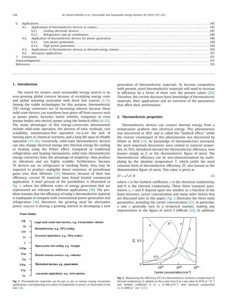
The search for cleaner, more sustainable energy sources is anever-growing global concern because of escalating energy costsand global warming associated with fossil fuel sources [1–5].Among the viable technologies for this purpose, thermoelectric(TE) energy converters are of increasing interest because thesesolid-state devices can transform heat given off from sources suchas power plants, factories, motor vehicles, computers or evenhuman bodies into electric power using the Seebeck effect [6–12].The many advantages of this energy-conversion phenomenoninclude solid-state operation, the absence of toxic residuals, vastscalability, maintenance-free operation vis-à-vis the lack ofmoving parts or chemical reactions, and a long life span of reliableoperation [13–16]. Conversely, solid-state thermoelectric devicescan also change electrical energy into thermal energy for coolingor heating using the Peltier effect. Compared to traditionalrefrigeration and heating mechanisms, solid-state thermoelectricenergy converters have the advantage of simplicity; they produceno vibrations and are highly scalable. Furthermore, becauseTE devices use no refrigerants or working fluids, they may beexpected to produce negligible direct emissions of greenhousegases over their lifetimes [17]. However, because of their lowefficiency, current TE materials have found limited commercialapplication. A brief perusal of the possibilities is illustrated inFig. 1, where the different scales of energy generation that arerepresented are relevant to different applications [18]. The pro-blem remains that the efficiency of today's thermoelectric materialis inadequate to compete with conventional power generation andrefrigeration [19]. Moreover, the growing need for alternativepower sources is driving a growing interest in developing a new
generation of thermoelectric materials. To become competitivewith present, novel thermoelectric materials will need to increasein efficiency by a factor of three over the present values [20].Therefore, this review discusses basic knowledge of thermoelectricmaterials, their applications and an overview of the parametersthat affect their performance.
2. Thermoelectric properties
Thermoelectric devices can convert thermal energy from atemperature gradient into electrical energy. This phenomenonwas discovered in 1821 and is called the “Seebeck effect,” whilethe reverse counterpart of this phenomenon was discovered byPeltier in 1834 [13]. As knowledge of thermoelectrics increased,the most important discoveries were related to material proper-ties. In 1911, Altenkirch derived the thermoelectric efficiency, nowknown simply as Z, or the thermoelectric figure of merit. Thethermoelectric efficiency can be non-dimensionalized by multi-plying by the absolute temperature T, which yields the mostcommon form of thermoelectric efficiency, ZT, also known as thedimensionless figure of merit. This value is given as
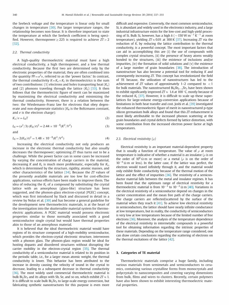
ZT ¼ α2sT=K ð1Þwhere α is the Seebeck coefficient, s is the electrical conductivity,and K is the thermal conductivity. These three transport para-meters α, s and K depend upon one another as a function of theband structure, carrier concentration and many other factors thatare discussed later in this paper; Fig. 2 illustrates the three mainparameters, including the carrier concentration [21]. In particular,α and s generally vary in a reciprocal manner, making anyimprovement in the figure of merit Z difficult [22]. In addition,
Fig. 1. Thermoelectric materials can be put to use in various energy conversionapplications, encompassing ten orders of magnitude in power, as illustrated in thetext [18].
Fig. 2. Maximizing the efficiency (ZT) of a thermoelectric involves a compromise ofthermal conductivity (k; plotted on the y-axis from 0 to a top value of 10Wm–1 K–1)and Seebeck coefficient (S or α; 0–500 μV K–1) with electrical conductivity(s; 0–5000 Ω–1 cm–1) [21].
M. Hamid Elsheikh et al. / Renewable and Sustainable Energy Reviews 30 (2014) 337–355338

the electrical conductivity and the Seebeck coefficient are inver-sely related, so it is not generally possible to increase the thermo-electric power factor above a particular optimal value for a bulkmaterial [23]. However, ideal thermoelectric materials would havea high electrical conductivity to allow the conduction of electricity,which would create a potential difference across the sample, and alow thermal conductivity to maintain the temperature gradientbetween the hot and cold side [24]. Early work in thermoelectricsresulted in very small values of Z because the materials being used(mostly metals) did not possess ideal thermoelectric properties;i.e., metals possess both high electrical conductivity and highthermal conductivity. Most traditional materials exhibit a correla-tion between electrical and thermal conductivity. A material thatconducts electricity well, such as a metal, also conducts heat well,and a material that insulates heat, such as glass or ceramic, alsoinsulates electricity [21].
Many years of effort to increase ZT have not yet led to afundamental breakthrough. In fact, the history of thermoelectricmaterials can be characterized by the progress in increasing ZT, asshown in Fig. 3 [25]. Thus, for devices operating at room tem-perature (TE300 K), traditional thermoelectric materials, such asbismuth telluride (Bi2Te3) and lead telluride (PbTe), possess valuesof ZTE1 [26]. In recent years, work by Venkatasubramanian et al.[27] and Harman et al. [28] using superlattices and quantum dotsbased on these materials has increased their room room-temperature ZT to �2–2.4. These improvements in performa-nce are primarily the result of a reduction in lattice thermal
conductivity, and the thermoelectric power factor (α2s) is largelyunchanged. For practical purposes, a suitable high-performance TEmaterial should have a ZT of 44, and the achievement of this goalhas remained a formidable challenge [19]. However, commercialmaterials are available with ZTE1.
2.1. The Seebeck coefficient
A temperature difference between two points in a conductor orsemiconductor results in a voltage difference between these twopoints. Stated differently, a temperature gradient in a conductor orsemiconductor gives rise to a built-in electric field. This phenom-enon is called the Seebeck effect or the thermoelectric effect [29].The Seebeck coefficient gauges the magnitude of this effect. Thethermoelectric voltage developed per unit temperature differencein a conductor is called the Seebeck coefficient or thermopower.Only the net Seebeck voltage difference between different metalscan be measured [25]. In fact, it is via the Seebeck effect thatthermoelectric devices can act as electrical power generators [30].A schematic diagram of a simple solid-state thermoelectric refrig-erator or power generator operating based on the Seebeck effect isshown in Fig. 4.
The Seebeck coefficient is expressed in units of V/K (or, morecommonly, μV/K or μV/1C). It has been found that only a combina-tion of two different materials, a so-called thermocouple, exhibitsthe Seebeck effect. For two leads of the same material, no Seebeckeffect manifests, although both leads intrinsically possess aSeebeck coefficient, for reasons of symmetry. It is, however,present because the Seebeck effect is a bulk property and doesnot depend on either the specific arrangement of the leads or thematerial or the specific method of joining them [31]. Metals havedifferent thermoelectric sensitivities, or Seebeck coefficients. Forexample, iron has a Seebeck coefficient of 19 μV/1C at 0 1C, whichmeans that for every 1 1C difference in temperature, a positivethermoelectric emf (or Seebeck voltage) of 19 μV is induced in ironat temperatures near 0 1C. A negative thermoelectric electromotiveforce (emf) can also be induced in a metal, so Seebeck coefficientscan also have negative values. For example, constantan (a copper–nickel alloy) has a Seebeck coefficient of �35 μV/1C at 0 1C.Generally, most metals possess Seebeck coefficients of 10 μV/K orless, but semiconductor materials are promising for the construc-tion of thermocouples because they have Seebeck coefficients inexcess of 100 μV/K. It should be noted that the relation between
Fig. 4. A thermoelectric modules illustrating the versatility of these materials for use in solid-state thermoelectric refrigeration or in power generation. The thermoelectricmodule is composed of an n-type and a p-type semiconducting material connected electrically in series through metallic electrical contact pads and thermally in parallelbetween ceramic ends [30].
Fig. 3. ZT of many typical thermoelectric materials as a function of year [25].
M. Hamid Elsheikh et al. / Renewable and Sustainable Energy Reviews 30 (2014) 337–355 339
the Seebeck voltage and the temperature is linear only for smallchanges in temperature [30]. For larger temperature ranges, therelationship becomes non-linear. It is therefore important to statethe temperature at which the Seebeck coefficient is being speci-fied. However, thermopowerZ225 is required to achieve ZT42[32].
2.2. Thermal conductivity
A high-quality thermoelectric material must have a highelectrical conductivity, a high thermopower, and a low thermalconductivity. Because the first two are determined only by theelectronic properties of the material, they are often combined intothe quantity PF¼α2s, referred to as the ‘power factor.’ In contrast,the thermal conductivity K¼KeþKL in thermoelectrics is the sumof two contributions: (1) electrons and holes transporting heat (Ke)and (2) phonons traveling through the lattice (KL) [33]. It thenfollows that the thermoelectric figure of merit can be maximizedby maximizing the electrical conductivity and minimizing thethermal conductivity. However, there is a relation between thetwo: the Wiedemann–Franz law for electrons that obey degen-erate and non-degenerate statistics (KB is the Boltzmann constant,and e is the electron charge):
Ke=s¼ L0T ð2Þ
L0 ¼ ðπ2=3Þ ðKB=eÞ2 ¼ 2:44� 10�8ðK2=V2Þ ð3Þand
L0 ¼ 2ðKB=eÞ2 ¼ 1:48� 10�8ðK2=V2Þ ð4ÞIncreasing the electrical conductivity not only produces an
increase in the electronic thermal conductivity but also usuallydecreases the thermopower; optimizing ZT thus turns out to be achallenge. While the power factor can in some cases be increasedby varying the concentration of charge carriers in the material,decreasing K and KL is much more problematic, especially for KL,which is determined by the structure, rigidity, atomic masses, andother characteristics of the lattice [34]. Because the ZT values ofthe presently available materials are too low for cost-effectiveapplications, various efforts have been made to improve them. Theidea of reducing the KL of a compound by substituting the crystallattice with an amorphous (glass-like) structure has beensuggested, and the phonon-glass electron-crystal (PGEC) concept,which was first introduced by Slack and discussed in detail in areview by Nolas et al. [30] and has become a general guideline forthe development new thermoelectric materials, is at the heart ofthe investigation into the skutterudite material system for thermo-electric applications. A PGEC material would possess electronicproperties similar to those normally associated with a goodsemiconductor single crystal but would have thermal propertiesakin to those of an amorphous material.
It is believed that the ideal thermoelectric material would haveregions of its structure composed of a high-mobility semiconductor,which provides the electron-crystal electronic structure, interwovenwith a phonon glass. The phonon-glass region would be ideal forhosting dopants and disordered structures without disrupting thecarrier mobility in the electron-crystal region [35]. The thermalconductivity of a semiconductor material is related to its position inthe periodic table, i.e., for a larger mean atomic weight, the thermalconductivity is lower. This behavior has been attributed to theincrease in density causing the velocity of sound in the crystal todecrease, leading to a subsequent decrease in thermal conductivity[36]. The most widely used commercial thermoelectric material isbulk Bi2Te3 and its alloys with Sb, Se, and so on, which exhibit ZTE1.It is difficult to scale bulk Bi2Te3 to large-scale energy conversion, butfabricating synthetic nanostructures for this purpose is even more
difficult and expensive. Conversely, the most common semiconductor,Si, is abundant and widely used in the electronics industry, and a largeindustrial infrastructure exists for the low-cost and high-yield proces-sing of Si. Bulk Si, however, has a high k (�150Wm�1 K�1 at roomtemperature), yielding ZTE0.01 at 300 K [37]. Increasing ZT via thereduction of K, by reducing the lattice contribution to the thermalconductivity, is a powerful concept. The most important factors thatcan aid in accomplishing this are (i) the use of compounds withcomplex crystal structures, (ii) the presence of heavy atoms weaklybonded to the structures, (iii) the existence of inclusions and/orimpurities, (iv) the formation of solid solutions and (v) the existenceof a large number of grain boundaries [38]. The introduction ofnanostructure has also become a potential tool for reducing K andconsequently increasing ZT. This concept has revolutionized the fieldof TE because, the utilization of nanostructures has led to theachievement of ZT values of approximately 1–2 compared to o1for bulk materials. The nanostructured BixSb2�xTe3 have been shownto exhibit significantly improved ZTE 1.4 at 100 1C, mostly because ofthe reduced KL [37]. However, it is difficult to scale up these super-lattices for large-volume energy-conversion applications because oflimitations in both heat transfer and cost. Joshi et al. [39] investigatedthe enhanced thermoelectric figure of merit in nanostructured p-typesilicon germanium bulk alloys and found that this ZT enhancement ismost likely attributable to the increased phonon scattering at thegrain boundaries and crystal defects formed by lattice distortion, withsome contribution from the increased electron power factor at hightemperatures.
2.3. Electrical resistivity (ρ)
Electrical resistivity is an important material-dependent propertythat is usually a function of temperature. The value of ρ at roomtemperature is indicative of whether a material is an insulator (ρ is onthe order of 106 Ωm or more) or a metal (ρ is on the order of10�6 Ωm or less). In the latter case, if the lattice was perfect, theelectron would travel infinitely through it, and the material wouldonly exhibit finite conductivity because of the thermal motion of thelattice and the effect of impurities [36]. The resistivity of a semicon-ductor material falls between the metal and insulator regimes. It hasbeen found that the optimum range of electrical resistivity for athermoelectric material is from 10�3 to 10�2 Ωm [40]. Variations inthe electrical resistivity of a semiconductor depend on changes in thecarrier concentration and the mean free path of the charge carriers.The charge carriers are reflected/scattered by the surface of thematerial when they reach it [41]. To achieve low electrical resistivityin semiconductors, the lattice should have nearly infinite conductanceat low temperatures, but in reality, the conductivity of semiconductorsis very low at low temperatures because of the limited number of freeelectrons [36]. Moreover, the analysis of the temperature dependenceof the electrical resistivity in intermetallic compounds is a powerfultool for obtaining information regarding the intrinsic properties ofthese materials. Depending on the temperature range considered, onecan draw certain conclusions regarding the scattering of electrons onthe thermal excitations of the lattice [42].
3. Categories of TE material
Thermoelectric materials comprise a huge family, includingvarious materials from semimetals and semiconductors to cera-mics, containing various crystalline forms from monocrystals andpolycrystals to nanocomposites and covering varying dimensionsfrom bulk, films and wires to clusters. Recently, certain polymershave also been shown to exhibit interesting thermoelectric mate-rial properties.
M. Hamid Elsheikh et al. / Renewable and Sustainable Energy Reviews 30 (2014) 337–355340
3.1. Metal-based thermoelectrics
The history of applications of thermoelectric materials isstrongly associated with their efficiency. The earliest applicationof the thermoelectric effect was in metal thermocouples, whichhave been used to measure temperature and radiant energy formany years [25]. However, metals possess very high electricalconductivity and very high thermal conductivity. Several TEmaterials containing heavy metals such as Bi, Sb, Pb and Te havebeen developed so far; these materials are mostly toxic andunstable at high temperatures (�1000 K) [43]. Therefore, metaloxides that exhibit good TE performance are in high demandbecause metal oxides are environmentally friendly and essentiallystable at high temperatures [43]. Watanabe et al. [44] measuredthe temperature dependence of the electrical resistivity and thethermoelectric power of (Ni1�xMx)Mn2O4 (M¼Zn and Mg, x¼0,0.1 and 0.2), and they reported that the activation energy forelectrical conduction is increased above a certain temperature(�450 1C). In the low-temperature region, the absolute value ofthe thermoelectric power is increased by Mg substitution, and thethermoelectric powers of all samples are found to change signfrom negative to positive as the temperature increases.
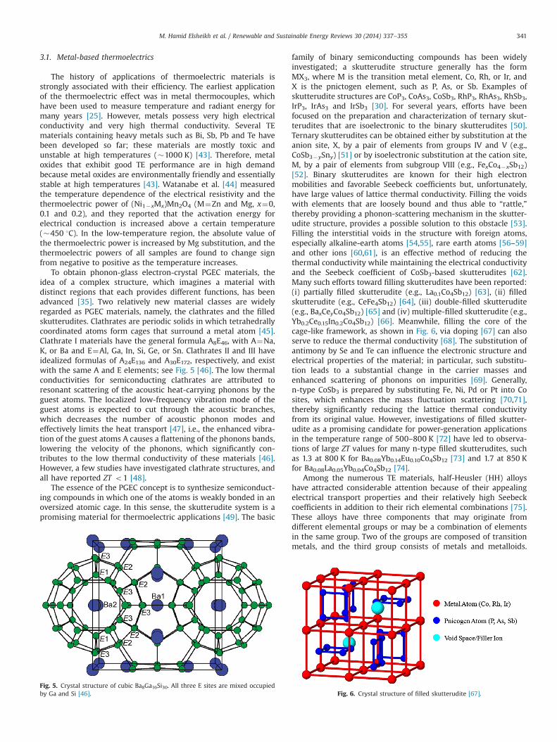
To obtain phonon-glass electron-crystal PGEC materials, theidea of a complex structure, which imagines a material withdistinct regions that each provides different functions, has beenadvanced [35]. Two relatively new material classes are widelyregarded as PGEC materials, namely, the clathrates and the filledskutterudites. Clathrates are periodic solids in which tetrahedrallycoordinated atoms form cages that surround a metal atom [45].Clathrate I materials have the general formula A8E46, with A¼Na,K, or Ba and E¼Al, Ga, In, Si, Ge, or Sn. Clathrates II and III haveidealized formulas of A24E136 and A30E172, respectively, and existwith the same A and E elements; see Fig. 5 [46]. The low thermalconductivities for semiconducting clathrates are attributed toresonant scattering of the acoustic heat-carrying phonons by theguest atoms. The localized low-frequency vibration mode of theguest atoms is expected to cut through the acoustic branches,which decreases the number of acoustic phonon modes andeffectively limits the heat transport [47], i.e., the enhanced vibra-tion of the guest atoms A causes a flattening of the phonons bands,lowering the velocity of the phonons, which significantly con-tributes to the low thermal conductivity of these materials [46].However, a few studies have investigated clathrate structures, andall have reported ZT o1 [48].
The essence of the PGEC concept is to synthesize semiconduct-ing compounds in which one of the atoms is weakly bonded in anoversized atomic cage. In this sense, the skutterudite system is apromising material for thermoelectric applications [49]. The basic
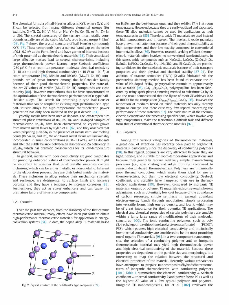
family of binary semiconducting compounds has been widelyinvestigated; a skutterudite structure generally has the formMX3, where M is the transition metal element, Co, Rh, or Ir, andX is the pnictogen element, such as P, As, or Sb. Examples ofskutterudite structures are CoP3, CoAs3, CoSb3, RhP3, RhAs3, RhSb3,IrP3, IrAs3 and IrSb3 [30]. For several years, efforts have beenfocused on the preparation and characterization of ternary skut-terudites that are isoelectronic to the binary skutterudites [50].Ternary skutterudites can be obtained either by substitution at theanion site, X, by a pair of elements from groups IV and V (e.g.,CoSb3�ySny) [51] or by isoelectronic substitution at the cation site,M, by a pair of elements from subgroup VIII (e.g., FexCo4�xSb12)[52]. Binary skutterudites are known for their high electronmobilities and favorable Seebeck coefficients but, unfortunately,have large values of lattice thermal conductivity. Filling the voidswith elements that are loosely bound and thus able to “rattle,”thereby providing a phonon-scattering mechanism in the skutter-udite structure, provides a possible solution to this obstacle [53].Filling the interstitial voids in the structure with foreign atoms,especially alkaline-earth atoms [54,55], rare earth atoms [56–59]and other ions [60,61], is an effective method of reducing thethermal conductivity while maintaining the electrical conductivityand the Seebeck coefficient of CoSb3-based skutterudites [62].Many such efforts toward filling skutterudites have been reported:(i) partially filled skutterudite (e.g., La0.1Co4Sb12) [63], (ii) filledskutterudite (e.g., CeFe4Sb12) [64], (iii) double-filled skutterudite(e.g., BaxCeyCo4Sb12) [65] and (iv) multiple-filled skutterudite (e.g.,Yb0.2Ce0.15In0.2Co4Sb12) [66]. Meanwhile, filling the core of thecage-like framework, as shown in Fig. 6, via doping [67] can alsoserve to reduce the thermal conductivity [68]. The substitution ofantimony by Se and Te can influence the electronic structure andelectrical properties of the material; in particular, such substitu-tion leads to a substantial change in the carrier masses andenhanced scattering of phonons on impurities [69]. Generally,n-type CoSb3 is prepared by substituting Fe, Ni, Pd or Pt into Cosites, which enhances the mass fluctuation scattering [70,71],thereby significantly reducing the lattice thermal conductivityfrom its original value. However, investigations of filled skutter-udite as a promising candidate for power-generation applicationsin the temperature range of 500–800 K [72] have led to observa-tions of large ZT values for many n-type filled skutterudites, suchas 1.3 at 800 K for Ba0.08Yb0.14Eu0.10Co4Sb12 [73] and 1.7 at 850 Kfor Ba0.08La0.05Yb0.04Co4Sb12 [74].
Among the numerous TE materials, half-Heusler (HH) alloyshave attracted considerable attention because of their appealingelectrical transport properties and their relatively high Seebeckcoefficients in addition to their rich elemental combinations [75].These alloys have three components that may originate fromdifferent elemental groups or may be a combination of elementsin the same group. Two of the groups are composed of transitionmetals, and the third group consists of metals and metalloids.
Fig. 6. Crystal structure of filled skutterudite [67].Fig. 5. Crystal structure of cubic Ba8Ga16Si30. All three E sites are mixed occupiedby Ga and Si [46].
M. Hamid Elsheikh et al. / Renewable and Sustainable Energy Reviews 30 (2014) 337–355 341
The chemical formula of half-Heusler alloys is XYZ, where X, Y, andZ can be selected from many different elemental groups (forexample, X¼Ti, Zr, Hf, V, Mn, or Nb; Y¼Fe, Co, Ni, or Pt; Z¼Snor Sb). The crystal structures of the ternary intermetallic com-pounds usually are of the cubic MgAgAs type (space group F-43m)[76]. Fig. 7 shows the crystal structure of half-Heusler compoundsXYZ [77]. These compounds have a narrow band gap on the orderof 0.1–0.2 eV at the Fermi level and have garnered interest becauseof their potential as thermoelectric materials [78]. Their associatedlarge effective masses lead to several characteristics, includinglarge thermoelectric power factors, large Seebeck coefficients(250 μV K�1) at room temperature, moderate electrical resistivity(1–10 μΩ m) and high thermal conductivity (�10 W m�1 K�1) atroom temperature [79]. MNiSn and MCoSb (M¼Ti, Zr, Hf) com-pounds are of great interest among the half-Heusler familybecause of their good thermoelectric properties. The state-of-the-art ZT values of MNiSn (M¼Ti, Zr, Hf) compounds are closeto unity [80]. However, most efforts thus far have concentrated onthe optimization of the thermoelectric performance of n-type half-Heusler alloys. The search for promising p-type half-Heuslermaterials that can be coupled to existing high-performance n-typehalf-Heusler alloys for high-temperature thermoelectric powergeneration has only been initiated in the past decade [81].
Typically, metals have been used as dopants. The low-temperaturestructural phase transitions of Bi-, Pb-, In- and Sn-doped samples ofthermoelectric Zn4Sb3 have been characterized on crystals grownfrom molten metal fluxes by Nylén et al. [82], and they observed thatwhen preparing β-Zn4Sb3 in the presence of metals with low meltingpoints (Bi, Sn, In, and Pb), the additional metal atoms are unavoidablyincorporated in small concentrations (0.04–1.3 wt%), act as dopantsand alter the subtle balance between Zn disorder and Zn deficiency inZn4Sb3, which has dramatic consequences for its low-temperaturestructural behavior.
In general, metals with poor conductivity are good candidatesfor providing enhanced values of thermoelectric power. It mightbe important to consider that most metallic materials containinclusions, which can be either metallic or non-metallic. Inherentto the elaboration process, they are distributed inside the materi-als. These inclusions in alloys reduce their mechanical strengthand resilience, are detrimental to surface finish and increaseporosity, and they have a tendency to increase corrosion [83].Furthermore, they act as stress enhancers and can cause thepremature failure of in-service components.
3.2. Ceramics
Over the past two decades, from the discovery of the first ceramicthermoelectric material, many efforts have been put forth to obtainhigh-performance thermoelectric materials for application in energy-conversion systems [84]. To date, the doped alloy TE materials based
on Bi2Te3 are the best-known ones, and they exhibit ZTE1 at roomtemperature. However, because they are easily oxidized and vaporized,these TE alloy materials cannot be used for applications at hightemperatures in air [85]. Therefore, oxide TEmaterials are used insteadat high temperatures and in oxygen. Thermoelectric oxide materialshave drawn much attention because of their good thermal stability athigh temperatures and their low toxicity compared to conventionalintermetallic alloys [86]. However, research seeking efficient thermo-electric materials often involves no conventional semiconductors. Inthis sense, oxide compounds such as NaCo2O4, LaCoO3, (ZnO)mIn2O3,BaSnO3, BaPbO3, Ca3Co4O9, Sr1�xNdxTiO3 and Bi2Ca2Co2Ox are promis-ing candidates for thermoelectric materials because of their transportproperties and their physical and chemical stability [87–94]. Theaddition of titanate nanotubes (TNTs) (2 vol%) fabricated via thepressureless sintering method has been found to enhance the ZTvalue of Nb-doped SrTiO3 polycrystalline ceramic to approximately0.14 at 900 K [95]. (Ca1�xSrx)3Co4O9 polycrystalline has been fabri-cated by using spark plasma sintering method to substitute Ca by Sr,and the result demonstrated that the figure of merit ZT achieves 0.22at 1000 K for the composition (Ca0.995Sr0.005)3Co4O9 [96]. However, thefabrication of modules based on oxide materials has only recentlybegun to emerge, and there exist very few reports concerning theperformance of these materials [97]. The oxide nature of the thermo-electric elements and the processing specifications, which involve veryhigh temperatures, make the fabrication a difficult task and differentfrom that of conventional thermoelectric modules [97].
3.3. Polymers
Among the various categories of thermoelectric materials,a great deal of attention has recently been paid to organic TEmaterials, particularly since the discovery of conducting polymers[98]. In this regard, polymers are very attractive because they arelight, flexible, and suitable for room-temperature applications andbecause they generally require relatively simple manufacturingprocesses (i.e., spin coating and inkjet printing) compared tosemiconductor-based thermoelectrics. Polymers are intrinsicallypoor thermal conductors, which make them ideal for use asthermoelectrics, but their low electrical conductivity, Seebeckcoefficient, and stability have hampered their use in thermo-electric applications [99]. However, compared to inorganic TEmaterials, organic or polymer TE materials exhibit several inherentadvantages, such as potentially low cost because of the abundanceof carbon resources, simple synthesis in general, abundantelectron-energy bands through modulation, simple processinginto versatile forms, high energy density, and low k, which maybe of great importance for their potential TE applications. Thephysical and chemical properties of certain polymers are tunablewithin a fairly large range of modifications of their molecularstructures [100]. The ionic conducting polymers, such as poly(3,4-ethylenedi-oxythiophene):poly(styrenesulfonate) (PEDOT:PSS), which possess high electrical conductivity and intrinsicallylow thermal conductivity, are considered to be the most promisingnovel organic TE materials [98]. In a two-component nanocompo-site, the selection of a conducting polymer and an inorganicthermoelectric material may yield high thermoelectric powerand high electrical conductivity of the material. Because theseproperties are dependent on the particle size and morphology, it isinteresting to map the relation between the structural andelectrical properties of the material. Recently, various researchershave attempted to prepare nanocomposites/hybrids/heterostruc-tures of inorganic thermoelectrics with conducting polymers[101]. Table 1 summarizes the electrical conductivity s, Seebeckcoefficient α, thermal conductivity k and power factor PF as well asthe highest ZT value of a few typical polymer and polymer–inorganic TE nanocomposites. Du et al. [102] reviewed theFig. 7. Crystal structure of the half-Heusler type compounds [77].
M. Hamid Elsheikh et al. / Renewable and Sustainable Energy Reviews 30 (2014) 337–355342
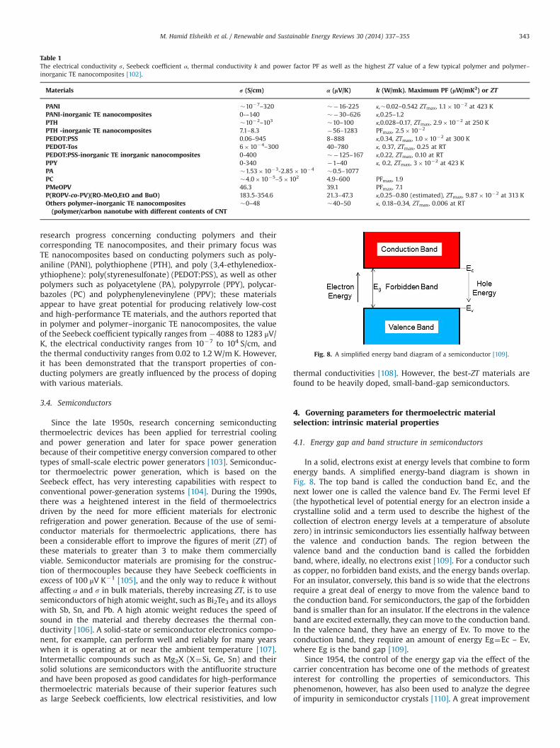
research progress concerning conducting polymers and theircorresponding TE nanocomposites, and their primary focus wasTE nanocomposites based on conducting polymers such as poly-aniline (PANI), polythiophene (PTH), and poly (3,4-ethylenediox-ythiophene): poly(styrenesulfonate) (PEDOT:PSS), as well as otherpolymers such as polyacetylene (PA), polypyrrole (PPY), polycar-bazoles (PC) and polyphenylenevinylene (PPV); these materialsappear to have great potential for producing relatively low-costand high-performance TE materials, and the authors reported thatin polymer and polymer–inorganic TE nanocomposites, the valueof the Seebeck coefficient typically ranges from �4088 to 1283 μV/K, the electrical conductivity ranges from 10�7 to 104 S/cm, andthe thermal conductivity ranges from 0.02 to 1.2 W/m K. However,it has been demonstrated that the transport properties of con-ducting polymers are greatly influenced by the process of dopingwith various materials.
3.4. Semiconductors
Since the late 1950s, research concerning semiconductingthermoelectric devices has been applied for terrestrial coolingand power generation and later for space power generationbecause of their competitive energy conversion compared to othertypes of small-scale electric power generators [103]. Semiconduc-tor thermoelectric power generation, which is based on theSeebeck effect, has very interesting capabilities with respect toconventional power-generation systems [104]. During the 1990s,there was a heightened interest in the field of thermoelectricsdriven by the need for more efficient materials for electronicrefrigeration and power generation. Because of the use of semi-conductor materials for thermoelectric applications, there hasbeen a considerable effort to improve the figures of merit (ZT) ofthese materials to greater than 3 to make them commerciallyviable. Semiconductor materials are promising for the construc-tion of thermocouples because they have Seebeck coefficients inexcess of 100 μV K�1 [105], and the only way to reduce k withoutaffecting α and s in bulk materials, thereby increasing ZT, is to usesemiconductors of high atomic weight, such as Bi2Te3 and its alloyswith Sb, Sn, and Pb. A high atomic weight reduces the speed ofsound in the material and thereby decreases the thermal con-ductivity [106]. A solid-state or semiconductor electronics compo-nent, for example, can perform well and reliably for many yearswhen it is operating at or near the ambient temperature [107].Intermetallic compounds such as Mg2X (X¼Si, Ge, Sn) and theirsolid solutions are semiconductors with the antifluorite structureand have been proposed as good candidates for high-performancethermoelectric materials because of their superior features suchas large Seebeck coefficients, low electrical resistivities, and low
thermal conductivities [108]. However, the best-ZT materials arefound to be heavily doped, small-band-gap semiconductors.
4. Governing parameters for thermoelectric materialselection: intrinsic material properties
4.1. Energy gap and band structure in semiconductors
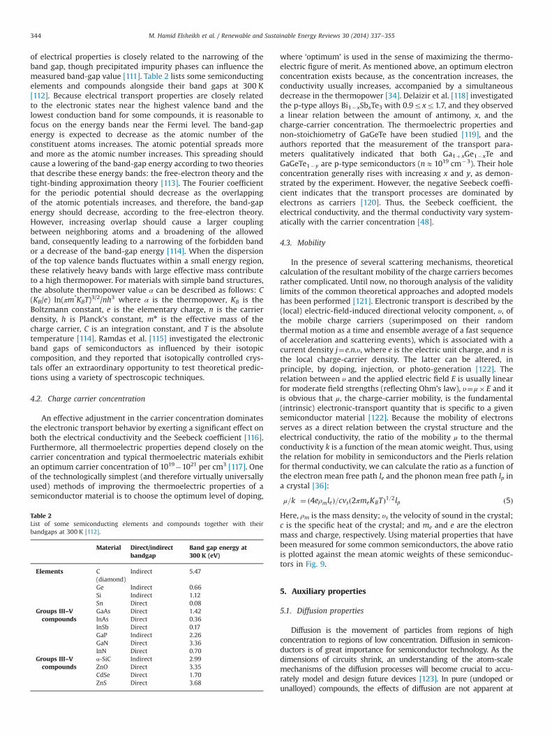
In a solid, electrons exist at energy levels that combine to formenergy bands. A simplified energy-band diagram is shown inFig. 8. The top band is called the conduction band Ec, and thenext lower one is called the valence band Ev. The Fermi level Ef(the hypothetical level of potential energy for an electron inside acrystalline solid and a term used to describe the highest of thecollection of electron energy levels at a temperature of absolutezero) in intrinsic semiconductors lies essentially halfway betweenthe valence and conduction bands. The region between thevalence band and the conduction band is called the forbiddenband, where, ideally, no electrons exist [109]. For a conductor suchas copper, no forbidden band exists, and the energy bands overlap.For an insulator, conversely, this band is so wide that the electronsrequire a great deal of energy to move from the valence band tothe conduction band. For semiconductors, the gap of the forbiddenband is smaller than for an insulator. If the electrons in the valenceband are excited externally, they can move to the conduction band.In the valence band, they have an energy of Ev. To move to theconduction band, they require an amount of energy Eg¼Ec – Ev,where Eg is the band gap [109].
Since 1954, the control of the energy gap via the effect of thecarrier concentration has become one of the methods of greatestinterest for controlling the properties of semiconductors. Thisphenomenon, however, has also been used to analyze the degreeof impurity in semiconductor crystals [110]. A great improvement
Fig. 8. A simplified energy band diagram of a semiconductor [109].
Table 1The electrical conductivity s, Seebeck coefficient α, thermal conductivity k and power factor PF as well as the highest ZT value of a few typical polymer and polymer–inorganic TE nanocomposites [102].
Materials r (S/cm) α (lV/K) k (W/mk). Maximum PF (lW/mK2) or ZT
PANI �10�7–320 ��16-225 κ,�0.02–0.542 ZTmax, 1.1�10�2 at 423 KPANI-inorganic TE nanocomposites 0-–140 ��30–626 κ,0.25–1.2PTH �10�2–103 �10–100 κ,0.028–0.17, ZTmax, 2.9�10�2 at 250 KPTH -inorganic TE nanocomposites 7.1–8.3 �56–1283 PFmax, 2.5�10�2
PEDOT:PSS 0.06–945 8–888 κ,0.34, ZTmax, 1.0�10�2 at 300 KPEDOT-Tos 6�10�4–300 40–780 κ, 0.37, ZTmax, 0.25 at RTPEDOT:PSS-inorganic TE inorganic nanocomposites 0-400 ��125–167 κ,0.22, ZTmax, 0.10 at RTPPY 0-340 �1–40 κ, 0.2, ZTmax, 3�10�2 at 423 KPA �1.53�10�3-2.85�10�4 �0.5–1077PC �4.0�10�5–5�102 4.9–600 PFmax, 1.9PMeOPV 46.3 39.1 PFmax, 7.1P(ROPV-co-PV)(RO-MeO,EtO and BuO) 183.5-354.6 21.3–47.3 κ,0.25–0.80 (estimated), ZTmax, 9.87�10�2 at 313 KOthers polymer–inorganic TE nanocomposites(polymer/carbon nanotube with different contents of CNT
�0–48 �40–50 κ, 0.18–0.34, ZTmax, 0.006 at RT
M. Hamid Elsheikh et al. / Renewable and Sustainable Energy Reviews 30 (2014) 337–355 343
of electrical properties is closely related to the narrowing of theband gap, though precipitated impurity phases can influence themeasured band-gap value [111]. Table 2 lists some semiconductingelements and compounds alongside their band gaps at 300 K[112]. Because electrical transport properties are closely relatedto the electronic states near the highest valence band and thelowest conduction band for some compounds, it is reasonable tofocus on the energy bands near the Fermi level. The band-gapenergy is expected to decrease as the atomic number of theconstituent atoms increases. The atomic potential spreads moreand more as the atomic number increases. This spreading shouldcause a lowering of the band-gap energy according to two theoriesthat describe these energy bands: the free-electron theory and thetight-binding approximation theory [113]. The Fourier coefficientfor the periodic potential should decrease as the overlappingof the atomic potentials increases, and therefore, the band-gapenergy should decrease, according to the free-electron theory.However, increasing overlap should cause a larger couplingbetween neighboring atoms and a broadening of the allowedband, consequently leading to a narrowing of the forbidden bandor a decrease of the band-gap energy [114]. When the dispersionof the top valence bands fluctuates within a small energy region,these relatively heavy bands with large effective mass contributeto a high thermopower. For materials with simple band structures,the absolute thermopower value α can be described as follows: C(KB/e) ln(πm*KBT)3/2/nh3 where α is the thermopower, KB is theBoltzmann constant, e is the elementary charge, n is the carrierdensity, h is Planck's constant, mn is the effective mass of thecharge carrier, C is an integration constant, and T is the absolutetemperature [114]. Ramdas et al. [115] investigated the electronicband gaps of semiconductors as influenced by their isotopiccomposition, and they reported that isotopically controlled crys-tals offer an extraordinary opportunity to test theoretical predic-tions using a variety of spectroscopic techniques.
4.2. Charge carrier concentration
An effective adjustment in the carrier concentration dominatesthe electronic transport behavior by exerting a significant effect onboth the electrical conductivity and the Seebeck coefficient [116].Furthermore, all thermoelectric properties depend closely on thecarrier concentration and typical thermoelectric materials exhibitan optimum carrier concentration of 1019�1021 per cm3 [117]. Oneof the technologically simplest (and therefore virtually universallyused) methods of improving the thermoelectric properties of asemiconductor material is to choose the optimum level of doping,
where ‘optimum’ is used in the sense of maximizing the thermo-electric figure of merit. As mentioned above, an optimum electronconcentration exists because, as the concentration increases, theconductivity usually increases, accompanied by a simultaneousdecrease in the thermopower [34]. Delaizir et al. [118] investigatedthe p-type alloys Bi1�xSbxTe3 with 0.9rxr1.7, and they observeda linear relation between the amount of antimony, x, and thecharge-carrier concentration. The thermoelectric properties andnon-stoichiometry of GaGeTe have been studied [119], and theauthors reported that the measurement of the transport para-meters qualitatively indicated that both Ga1þxGe1�xTe andGaGeTe1�y are p-type semiconductors (nE1019 cm�3). Their holeconcentration generally rises with increasing x and y, as demon-strated by the experiment. However, the negative Seebeck coeffi-cient indicates that the transport processes are dominated byelectrons as carriers [120]. Thus, the Seebeck coefficient, theelectrical conductivity, and the thermal conductivity vary system-atically with the carrier concentration [48].
4.3. Mobility
In the presence of several scattering mechanisms, theoreticalcalculation of the resultant mobility of the charge carriers becomesrather complicated. Until now, no thorough analysis of the validitylimits of the common theoretical approaches and adopted modelshas been performed [121]. Electronic transport is described by the(local) electric-field-induced directional velocity component, υ, ofthe mobile charge carriers (superimposed on their randomthermal motion as a time and ensemble average of a fast sequenceof acceleration and scattering events), which is associated with acurrent density j¼e.n.υ, where e is the electric unit charge, and n isthe local charge-carrier density. The latter can be altered, inprinciple, by doping, injection, or photo-generation [122]. Therelation between υ and the applied electric field E is usually linearfor moderate field strengths (reflecting Ohm's law), υ¼μ� E and itis obvious that μ, the charge-carrier mobility, is the fundamental(intrinsic) electronic-transport quantity that is specific to a givensemiconductor material [122]. Because the mobility of electronsserves as a direct relation between the crystal structure and theelectrical conductivity, the ratio of the mobility μ to the thermalconductivity k is a function of the mean atomic weight. Thus, usingthe relation for mobility in semiconductors and the Pierls relationfor thermal conductivity, we can calculate the ratio as a function ofthe electron mean free path le and the phonon mean free path lp ina crystal [36]:
μ=k� �¼ ð4eρmleÞ=cvsð2πmeKBTÞ1=2lp ð5ÞHere, ρm is the mass density; υs the velocity of sound in the crystal;c is the specific heat of the crystal; and me and e are the electronmass and charge, respectively. Using material properties that havebeen measured for some common semiconductors, the above ratiois plotted against the mean atomic weights of these semiconduc-tors in Fig. 9.
5. Auxiliary properties
5.1. Diffusion properties
Diffusion is the movement of particles from regions of highconcentration to regions of low concentration. Diffusion in semicon-ductors is of great importance for semiconductor technology. As thedimensions of circuits shrink, an understanding of the atom-scalemechanisms of the diffusion processes will become crucial to accu-rately model and design future devices [123]. In pure (undoped orunalloyed) compounds, the effects of diffusion are not apparent at
Table 2List of some semiconducting elements and compounds together with theirbandgaps at 300 K [112].
Material Direct/indirectbandgap
Band gap energy at300 K (eV)
Elements C(diamond)
Indirect 5.47
Ge Indirect 0.66Si Indirect 1.12Sn Direct 0.08
Groups III–Vcompounds
GaAs Direct 1.42InAs Direct 0.36InSb Direct 0.17GaP Indirect 2.26GaN Direct 3.36InN Direct 0.70
Groups III–Vcompounds
α-SiC Indirect 2.99ZnO Direct 3.35CdSe Direct 1.70ZnS Direct 3.68
M. Hamid Elsheikh et al. / Renewable and Sustainable Energy Reviews 30 (2014) 337–355344
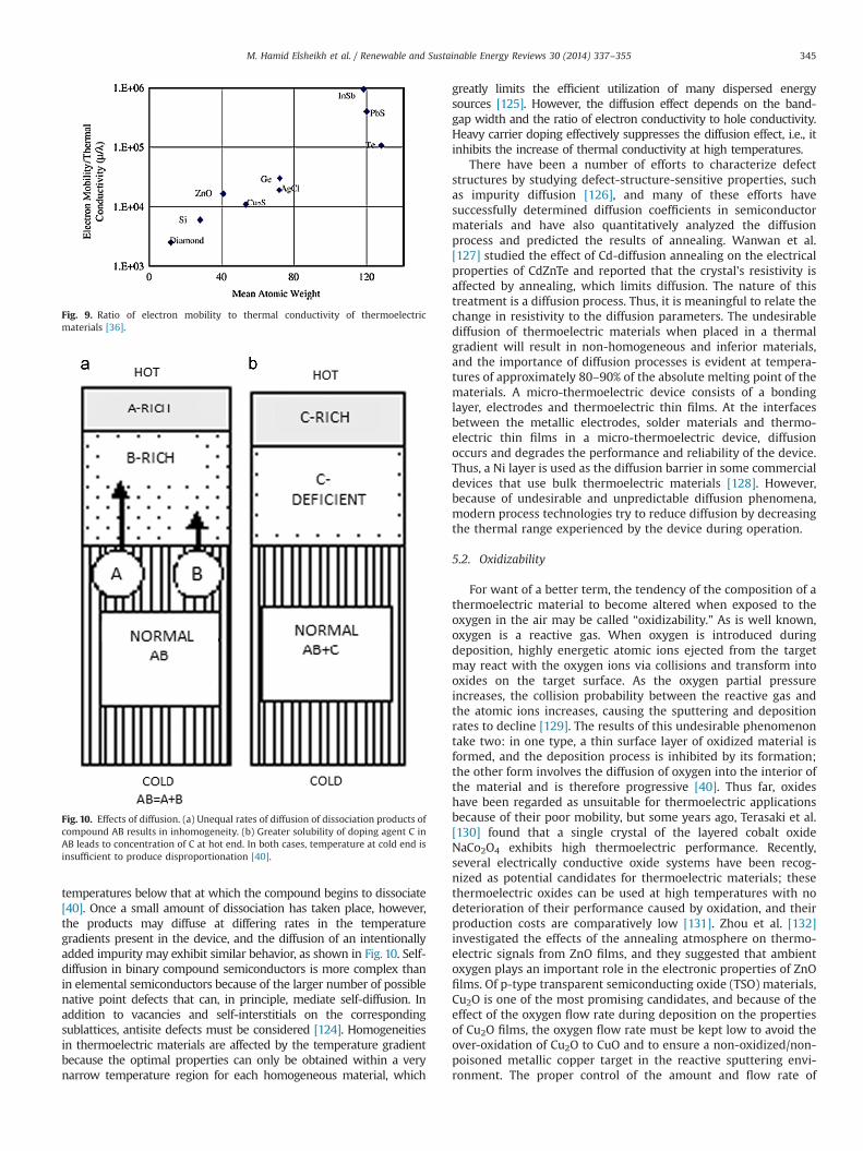
temperatures below that at which the compound begins to dissociate[40]. Once a small amount of dissociation has taken place, however,the products may diffuse at differing rates in the temperaturegradients present in the device, and the diffusion of an intentionallyadded impurity may exhibit similar behavior, as shown in Fig. 10. Self-diffusion in binary compound semiconductors is more complex thanin elemental semiconductors because of the larger number of possiblenative point defects that can, in principle, mediate self-diffusion. Inaddition to vacancies and self-interstitials on the correspondingsublattices, antisite defects must be considered [124]. Homogeneitiesin thermoelectric materials are affected by the temperature gradientbecause the optimal properties can only be obtained within a verynarrow temperature region for each homogeneous material, which
greatly limits the efficient utilization of many dispersed energysources [125]. However, the diffusion effect depends on the band-gap width and the ratio of electron conductivity to hole conductivity.Heavy carrier doping effectively suppresses the diffusion effect, i.e., itinhibits the increase of thermal conductivity at high temperatures.
There have been a number of efforts to characterize defectstructures by studying defect-structure-sensitive properties, suchas impurity diffusion [126], and many of these efforts havesuccessfully determined diffusion coefficients in semiconductormaterials and have also quantitatively analyzed the diffusionprocess and predicted the results of annealing. Wanwan et al.[127] studied the effect of Cd-diffusion annealing on the electricalproperties of CdZnTe and reported that the crystal's resistivity isaffected by annealing, which limits diffusion. The nature of thistreatment is a diffusion process. Thus, it is meaningful to relate thechange in resistivity to the diffusion parameters. The undesirablediffusion of thermoelectric materials when placed in a thermalgradient will result in non-homogeneous and inferior materials,and the importance of diffusion processes is evident at tempera-tures of approximately 80–90% of the absolute melting point of thematerials. A micro-thermoelectric device consists of a bondinglayer, electrodes and thermoelectric thin films. At the interfacesbetween the metallic electrodes, solder materials and thermo-electric thin films in a micro-thermoelectric device, diffusionoccurs and degrades the performance and reliability of the device.Thus, a Ni layer is used as the diffusion barrier in some commercialdevices that use bulk thermoelectric materials [128]. However,because of undesirable and unpredictable diffusion phenomena,modern process technologies try to reduce diffusion by decreasingthe thermal range experienced by the device during operation.
5.2. Oxidizability
For want of a better term, the tendency of the composition of athermoelectric material to become altered when exposed to theoxygen in the air may be called “oxidizability.” As is well known,oxygen is a reactive gas. When oxygen is introduced duringdeposition, highly energetic atomic ions ejected from the targetmay react with the oxygen ions via collisions and transform intooxides on the target surface. As the oxygen partial pressureincreases, the collision probability between the reactive gas andthe atomic ions increases, causing the sputtering and depositionrates to decline [129]. The results of this undesirable phenomenontake two: in one type, a thin surface layer of oxidized material isformed, and the deposition process is inhibited by its formation;the other form involves the diffusion of oxygen into the interior ofthe material and is therefore progressive [40]. Thus far, oxideshave been regarded as unsuitable for thermoelectric applicationsbecause of their poor mobility, but some years ago, Terasaki et al.[130] found that a single crystal of the layered cobalt oxideNaCo2O4 exhibits high thermoelectric performance. Recently,several electrically conductive oxide systems have been recog-nized as potential candidates for thermoelectric materials; thesethermoelectric oxides can be used at high temperatures with nodeterioration of their performance caused by oxidation, and theirproduction costs are comparatively low [131]. Zhou et al. [132]investigated the effects of the annealing atmosphere on thermo-electric signals from ZnO films, and they suggested that ambientoxygen plays an important role in the electronic properties of ZnOfilms. Of p-type transparent semiconducting oxide (TSO) materials,Cu2O is one of the most promising candidates, and because of theeffect of the oxygen flow rate during deposition on the propertiesof Cu2O films, the oxygen flow rate must be kept low to avoid theover-oxidation of Cu2O to CuO and to ensure a non-oxidized/non-poisoned metallic copper target in the reactive sputtering envi-ronment. The proper control of the amount and flow rate of
Fig. 10. Effects of diffusion. (a) Unequal rates of diffusion of dissociation products ofcompound AB results in inhomogeneity. (b) Greater solubility of doping agent C inAB leads to concentration of C at hot end. In both cases, temperature at cold end isinsufficient to produce disproportionation [40].
Fig. 9. Ratio of electron mobility to thermal conductivity of thermoelectricmaterials [36].
M. Hamid Elsheikh et al. / Renewable and Sustainable Energy Reviews 30 (2014) 337–355 345

oxygen during deposition can produce good-quality p-type trans-parent Cu2O films with electrical resistivities ranging from 102 to104 Ω cm, hole mobilities of 1–10 cm2/V s, and optical band gaps of2.0–2.6 eV [133]. The synthesis and post-annealing effects on thetransport properties of thermoelectric oxide (ZnO)mIn2O3 ceramicshave been studied by Wang et al. [92], and they inferred that theoxygen defects or vacancies in the InO2 layers play an importantrole on both the electrical and thermal transport properties ofthese (ZnO)mIn2O3 ceramics. It has also been reported that theresistivity, carrier concentration, and Hall mobility of Z5IO filmsdepend strongly on the annealing temperature and ambientatmosphere. Measurements of the Seebeck coefficient and elec-trical resistivity are most likely among the most sensitive meansfor the detection of small amounts of diffusive oxidation [40].However, in some of the most-studied compounds, traces ofdiffusive oxidation that are visually and chemically undetectablecan so severely affect the Seebeck coefficient as to change its sign,and the resistivity can be increased by several decades as a resultof this process.
5.3. Brittleness
At low temperatures (To200 K), single crystals of the Bi–Sballoys exhibit the best thermoelectric performances, but thebrittleness of the single crystals is a problem in practical devices.To ameliorate this limitation, some efforts have been devoted tostudying the influence of the growth parameters on the mechan-ical properties of such alloys [134]. However, the requirements forproducing nanostructured TE materials are two-fold: improvetheir mechanical properties (reduce brittleness and improvemachining) and improve their TE properties (figure of merit)[135]. Moon et al. [136] prepared p-type Te-doped Bi2Te3–Sb2Te3compounds using rapid solidification and spark plasma sintering(SPS) techniques, and they reported that the solidified powdersconsisted of homogeneous thermoelectric phase and that as theSPS temperature increases, the microstructure becomes coarser,resulting in a reduction of the hardness. At present, rapid solidi-fication processes (RSPs) such as gas atomization and melt spin-ning have been reported to offer a novel opportunity for modifyingthe intrinsic brittleness and thermoelectric anisotropy of Bi–Te-based thermoelectric materials by forming a fine-grained andhomogeneous microstructure [137]. One reason for the broadinterest in hardness (H) testing is that the microstructure (andhardness) of materials can change dramatically with alloying, andthe machinability of brittle materials also has been correlated withhardness. Thus, the compositional dependence of H is significantbecause H is related to other mechanical properties. For LAST(lead–antimony–silver–tellurium), the fabrication of thermoelec-tric (TE) modules for waste-heat recovery will require the machin-ing of perhaps several hundred (or more) individual TE legs.Because machinability and wear resistance are functions of H forother brittle materials [138], Zhou et al. [139] investigated thethermal stability and elastic properties of Mg2X (X¼Si, Ge, Sn, Pb)phases from first-principle calculations and calculated the bulkmoduli B, shear moduli G, Young's moduli E and Poisson ratios υ;they reported that Mg2Si, Mg2Ge, Mg2Sn and Mg2Pb are all brittle.
5.4. Compression and shear strength
The average strength (the mean of the strength distribution)and Young's modulus (which characterizes the stress–strainresponse of a brittle material prior to fracture) are fundamentalto understand the mechanical properties of a TE material in apractical device [140]. Enhancement of the mechanical strength ofa TE module will render it more robust. The largest improvementmust be in the shear strength, which is the weakest point of many
TE modules. The compressive strength also must be increased,especially near the perimeter of the module. Such additionalcompressive strength will be especially useful in preventingdamage to the module if, during the assembly process, clampingforces are accidentally applied unevenly to the module. Not onlydoes the brittleness of the material limit the resistance of thedevice to mechanical and thermal shocks, but the cutting andfabrication of the arms themselves require that the materials usednot be too brittle. Hong et al. [141] studied the thermoelectricproperties of novel n-type 95% Bi2Te2 5% Bi2Se3 alloys by gasatomizing and extrusion process, and they reported that thecompressive strengths of the compounds hot extruded at 16:1and 25:1 were 160 and 160 MPa, respectively. The figures of meritZ of the compounds extruded at 16:1 and 25:1 were 2.50 and2.07�10�3 K�1, respectively, because of the different grain sizesinduced by the differences in deformation caused by varying theextrusion ratio. The shear strength of aged CoSb3/Ti/Mo–Cu TEjoints has been investigated [142], and the results indicated thejoints possessed sufficient strength after aging at 575 1C for 720 h.Moreover, the CoSb3/Ti/W80Cu20 elements exhibit sufficient shearstrength and good electrical contact for the reliability of a thermo-electric device [143]. Experiments conducted by Zhao et al. [144]on nanostructured materials, such as nanoparticles, nanowires,nanotubes, nanopillars, thin films, and nanocrystals, have revealeda host of “ultra-strength” phenomena, which are defined by thestresses in a material component generally increasing to a sig-nificant fraction (41/10) of its ideal strength – the highestachievable stress of a defect-free crystal at zero temperature.However, while thermoelectric modules exhibit relatively highmechanical strength in the compression mode, their shearstrength is comparatively low.
5.5. Coefficient of thermal expansion (CTE)
Thermal expansion is critical, as devices for high-temperatureapplications will be subjected to extreme temperature fluctua-tions. This property, defined as the fractional change in length orvolume with a unit change in temperature, affects several aspectsof the design of thermoelectric devices. Generally, the thermalexpansion coefficient α (α¼(ΔL/L0)/(T2�T1)) varies inversely withthe melting temperature (Tm), and it has been empirically con-firmed that the product αTm is a constant for many substances.This means that a material with high Tm should exhibit low α[145]. The CTE of TE materials is of critical importance because theshear stress is proportional to the temperature gradient, and thelarger the heterogeneity in the thermal expansion coefficient of amaterial is, the larger is the shear stress that will result [146].Al-Merbati et al. [147] examined the influence of device geometryon thermal stress, thermal efficiency and output power, and theresult indicated that the presence of high stress can be attributedto the mismatch of thermal expansion coefficients between thepin and the hot plate, which generates high stress levels at theinterface between the hot plate and the pin. With respect to thespace group (in mathematics and geometry, a space group is asymmetry group, usually for three dimensions, that divides spaceinto discrete repeatable domains), the Pnma phase exhibited asmall but significant decrease in thermal expansion with increas-ing dopant levels, while the Imma phase exhibited no significantchange in CTE with increasing dopant levels. However, thesevalues can be considered representative of the behavior of a bulkpolycrystalline sample because of the independence of the ther-mal expansion from microstructure and porosity [148]. Tachibanaand Fang [149] estimated the thermal stress to investigate thereliability of thermoelectric devices by devices via temperature-cycling tests, and they claimed that it was obvious that the thermalstress was determined by the temperature difference, coefficients
M. Hamid Elsheikh et al. / Renewable and Sustainable Energy Reviews 30 (2014) 337–355346
of thermal expansion, die height, die cross section, substrate sizeand so on. However, no explicit relations among these parameterswere given. Rogl et al. [150] investigated the effects of highpressure torsion (HPT) processing on the structural, thermoelectricand mechanical properties of Sr0.07Ba0.07Yb0.07Co4Sb12, and theyreported that the thermal expansion coefficient below roomtemperature after processing was slightly lower than before HPT.The thermal expansion of the sample was measured above roomtemperature both parallel and perpendicular to the pressingdirection, and interesting results were obtained: the thermalexpansion coefficient calculated for the temperature range of600–700 K was the same as for the low-temperature region, butthe expansion behavior from room temperature to 550 K differedbetween the first and third measurements and requires furtherinvestigation. As the temperature increased from 300 to 550 K, thelength first reached a maximum and then was observed todecrease.
6. Applications
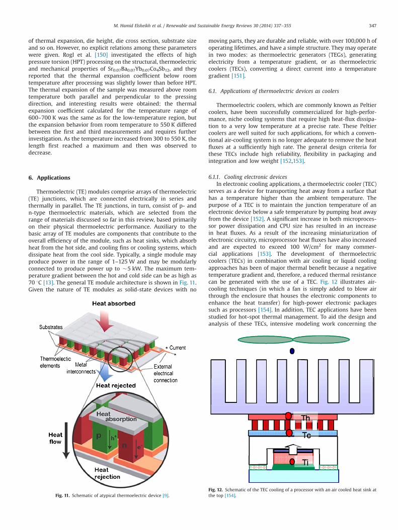
Thermoelectric (TE) modules comprise arrays of thermoelectric(TE) junctions, which are connected electrically in series andthermally in parallel. The TE junctions, in turn, consist of p- andn-type thermoelectric materials, which are selected from therange of materials discussed so far in this review, based primarilyon their physical thermoelectric performance. Auxiliary to thebasic array of TE modules are components that contribute to theoverall efficiency of the module, such as heat sinks, which absorbheat from the hot side, and cooling fins or cooling systems, whichdissipate heat from the cool side. Typically, a single module mayproduce power in the range of 1–125 W and may be modularlyconnected to produce power up to �5 kW. The maximum tem-perature gradient between the hot and cold side can be as high as70 1C [13]. The general TE module architecture is shown in Fig. 11.Given the nature of TE modules as solid-state devices with no
moving parts, they are durable and reliable, with over 100,000 h ofoperating lifetimes, and have a simple structure. They may operatein two modes: as thermoelectric generators (TEGs), generatingelectricity from a temperature gradient, or as thermoelectriccoolers (TECs), converting a direct current into a temperaturegradient [151].
6.1. Applications of thermoelectric devices as coolers
Thermoelectric coolers, which are commonly known as Peltiercoolers, have been successfully commercialized for high-perfor-mance, niche cooling systems that require high heat-flux dissipa-tion to a very low temperature at a precise rate. These Peltiercoolers are well suited for such applications, for which a conven-tional air-cooling system is no longer adequate to remove the heatfluxes at a sufficiently high rate. The general design criteria forthese TECs include high reliability, flexibility in packaging andintegration and low weight [152,153].
6.1.1. Cooling electronic devicesIn electronic cooling applications, a thermoelectric cooler (TEC)
serves as a device for transporting heat away from a surface thathas a temperature higher than the ambient temperature. Thepurpose of a TEC is to maintain the junction temperature of anelectronic device below a safe temperature by pumping heat awayfrom the device [152]. A significant increase in both microproces-sor power dissipation and CPU size has resulted in an increasein heat fluxes. As a result of the increasing miniaturization ofelectronic circuitry, microprocessor heat fluxes have also increasedand are expected to exceed 100 W/cm2 for many commer-cial applications [153]. The development of thermoelectriccoolers (TECs) in combination with air cooling or liquid coolingapproaches has been of major thermal benefit because a negativetemperature gradient and, therefore, a reduced thermal resistancecan be generated with the use of a TEC. Fig. 12 illustrates air-cooling techniques (in which a fan is simply added to blow airthrough the enclosure that houses the electronic components toenhance the heat transfer) for high-power electronic packagessuch as processors [154]. In addition, TEC applications have beenstudied for hot-spot thermal management. To aid the design andanalysis of these TECs, intensive modeling work concerning the
Fig. 11. Schematic of atypical thermoelectric device [9].Fig. 12. Schematic of the TEC cooling of a processor with an air cooled heat sink atthe top [154].
M. Hamid Elsheikh et al. / Renewable and Sustainable Energy Reviews 30 (2014) 337–355 347
performance of TECs has been carried out, such as that for thematerial Bi2Te3 [155]. Chang et al. [156] developed a theoreticalmodel of a thermal analogy network to predict the thermalperformance of a TEC with an air-cooling module. They reportedthat at a specific heat load, the TEC air-cooling module achieves itsbest cooling performance at an optimum input current between6 A and 7 A and for heat loads between 20 W and 100 W. Theirresult also demonstrated that the thermoelectric air-cooling mod-ule performs better at a lower heat load. Similarly, Huang et al.[157] demonstrated experimentally that the thermal performanceof a conventional water-cooling device can be effectively enhancedby integrating it with a thermoelectric cooler when the heat loadis below 57 W. Zhou and Yu [158] conducted detailed analyses ofthe optimal allocation of the finite thermal conductance betweenthe cold-side and hot-side heat exchangers of a TEC system. Theanalysis results when the constraint of the total thermal conduc-tance was considered demonstrated that the maximum coefficientof performance (COP) can exceed 1.5 when the finite total thermalconductance is optimally allocated. However, overall, the efficiencyof the hot-side heat exchanger parameters is usually the predo-minant factor in determining the overall performance of a TECsystem [158,159].
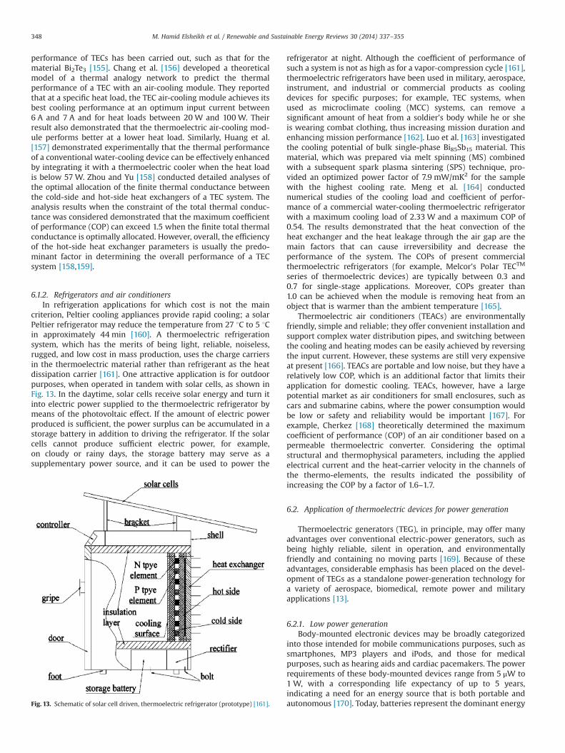
6.1.2. Refrigerators and air conditionersIn refrigeration applications for which cost is not the main
criterion, Peltier cooling appliances provide rapid cooling; a solarPeltier refrigerator may reduce the temperature from 27 1C to 5 1Cin approximately 44 min [160]. A thermoelectric refrigerationsystem, which has the merits of being light, reliable, noiseless,rugged, and low cost in mass production, uses the charge carriersin the thermoelectric material rather than refrigerant as the heatdissipation carrier [161]. One attractive application is for outdoorpurposes, when operated in tandem with solar cells, as shown inFig. 13. In the daytime, solar cells receive solar energy and turn itinto electric power supplied to the thermoelectric refrigerator bymeans of the photovoltaic effect. If the amount of electric powerproduced is sufficient, the power surplus can be accumulated in astorage battery in addition to driving the refrigerator. If the solarcells cannot produce sufficient electric power, for example,on cloudy or rainy days, the storage battery may serve as asupplementary power source, and it can be used to power the
refrigerator at night. Although the coefficient of performance ofsuch a system is not as high as for a vapor-compression cycle [161],thermoelectric refrigerators have been used in military, aerospace,instrument, and industrial or commercial products as coolingdevices for specific purposes; for example, TEC systems, whenused as microclimate cooling (MCC) systems, can remove asignificant amount of heat from a soldier's body while he or sheis wearing combat clothing, thus increasing mission duration andenhancing mission performance [162]. Luo et al. [163] investigatedthe cooling potential of bulk single-phase Bi85Sb15 material. Thismaterial, which was prepared via melt spinning (MS) combinedwith a subsequent spark plasma sintering (SPS) technique, pro-vided an optimized power factor of 7.9 mW/mK2 for the samplewith the highest cooling rate. Meng et al. [164] conductednumerical studies of the cooling load and coefficient of perfor-mance of a commercial water-cooling thermoelectric refrigeratorwith a maximum cooling load of 2.33 W and a maximum COP of0.54. The results demonstrated that the heat convection of theheat exchanger and the heat leakage through the air gap are themain factors that can cause irreversibility and decrease theperformance of the system. The COPs of present commercialthermoelectric refrigerators (for example, Melcor's Polar TECTM
series of thermoelectric devices) are typically between 0.3 and0.7 for single-stage applications. Moreover, COPs greater than1.0 can be achieved when the module is removing heat from anobject that is warmer than the ambient temperature [165].
Thermoelectric air conditioners (TEACs) are environmentallyfriendly, simple and reliable; they offer convenient installation andsupport complex water distribution pipes, and switching betweenthe cooling and heating modes can be easily achieved by reversingthe input current. However, these systems are still very expensiveat present [166]. TEACs are portable and low noise, but they have arelatively low COP, which is an additional factor that limits theirapplication for domestic cooling. TEACs, however, have a largepotential market as air conditioners for small enclosures, such ascars and submarine cabins, where the power consumption wouldbe low or safety and reliability would be important [167]. Forexample, Cherkez [168] theoretically determined the maximumcoefficient of performance (COP) of an air conditioner based on apermeable thermoelectric converter. Considering the optimalstructural and thermophysical parameters, including the appliedelectrical current and the heat-carrier velocity in the channels ofthe thermo-elements, the results indicated the possibility ofincreasing the COP by a factor of 1.6–1.7.
6.2. Application of thermoelectric devices for power generation
Thermoelectric generators (TEG), in principle, may offer manyadvantages over conventional electric-power generators, such asbeing highly reliable, silent in operation, and environmentallyfriendly and containing no moving parts [169]. Because of theseadvantages, considerable emphasis has been placed on the devel-opment of TEGs as a standalone power-generation technology fora variety of aerospace, biomedical, remote power and militaryapplications [13].
6.2.1. Low power generationBody-mounted electronic devices may be broadly categorized
into those intended for mobile communications purposes, such assmartphones, MP3 players and iPods, and those for medicalpurposes, such as hearing aids and cardiac pacemakers. The powerrequirements of these body-mounted devices range from 5 μW to1 W, with a corresponding life expectancy of up to 5 years,indicating a need for an energy source that is both portable andautonomous [170]. Today, batteries represent the dominant energyFig. 13. Schematic of solar cell driven, thermoelectric refrigerator (prototype) [161].
M. Hamid Elsheikh et al. / Renewable and Sustainable Energy Reviews 30 (2014) 337–355348
source for portable devices. Although the energy density ofbatteries has increased by a factor of 3 over the past 15 years, inmany cases, their presence has had a large impact on, or evendominated, the overall size and operational cost of portabledevices [170]. Furthermore, batteries contain chemical substancesor materials that are harmful to the environment, such as sulfuricacid, mercury, zinc, lithium, lead, nickel and cadmium, and exhibittoxicity that can cause damage to humans and the environment.For this reason, body-mounted TEGs are an attractive proposition,as they may be fabricated out of safer materials than Ni-Cd orlithium-ion batteries [13]. So far, a thermoelectric wristwatch thatis driven by body heat has appeared as one commercializedexample of body-mounted TEGs. Two known manufacturers ofthese TEG wristwatches are Seiko and Citizen; the Seiko watchtypically produces 300 mV of open-circuit voltage from a tem-perature gradient of 1.5 K, and its efficiency is approximately 0.1%[171].
6.2.2. High power generation(a) Waste heat thermoelectric generators: Traditionally, large-
scale electricity generation is achieved via the burning of fossilfuels (e.g., heat engines) or from nuclear or hydropower sources.Each of these technologies has some disadvantages in terms ofenvironmental impact. For example, the burning of fossil fuels hasbeen linked to environmental pollution and global warning, whilenuclear electricity carries a risk of nuclear meltdown, as demon-strated by the 2011 Fukushima disaster. TEGs circumvent theseproblems, as they generally offer a low environmental risk.Furthermore, TEGs are an intelligent way of mitigating the adverseeffects of global warming, as they are able to generate electricityby harvesting waste heat, such as heat that is the byproduct ofindustrial processes, such as the steelworks industry, and auto-mobile engines. Recognizing the potential of waste heat as anenergy resource, these two industries have been the main drivingforce behind the development of commercial TEGs for high-powerelectricity generation. The energy-conversion efficiency of a TEG(ηte) is determined by both the operating temperature of thegenerator and the unitless figures of merit (ZT) of the thermo-electric materials used, as follows:
ηte ¼ ððTh�TcÞ=ThÞ:ð√ð1þZTÞ�1Þ=ð√ð1þZTÞþTc=ThÞ ð6Þ
where Th is the hot-side temperature, and Tc is the cold-sidetemperature; these temperatures are selected based on the appli-cation of the TEG. Komatsu's Bi2Te3-based thermoelectric genera-tor, touted as the world's most efficient, has ηte¼7.2% and producesan output density of approximately 1 W/cm2 when operating atTc¼30 1C and Th¼280 1C [172]. In the case of waste-heat-recoverypower generation, several leading automobile manufacturers, suchas Volkswagen, Volvo, Ford and BMW, have been developing TEGwaste-heat-recovery systems to improve the fuel economy of theirautomobiles with potential power generated from the TEGs in therange of �1 kW. Even despite the currently low TEG efficiency,diligent harvesting of waste heat from resources such as auto-mobile exhaust via judicious design and fabrication methods andmaintenance strategies render TEGs a worthwhile technology forinvestment by these automobile manufacturers [171]. A TEG with aZT of 1.25 and an efficiency of approximately 10% could be used toharvest 35– 40% of the energy from the exhaust manifold, whichhas an average temperature of 250 1C, to generate useable powerthat would contribute directly to the operation of the equippedvehicle, which could increase fuel efficiency by up to 16% [173].Most of these automobile TEGs use BiTe-based bulk thermoelectricmaterials, as an optimal ZT in the temperature rangeo500 K maybe achieved using this compound, and therefore, the manufactur-ing processes for this compound have been extensively developed.
Table 3 presents the characteristics of available thermoelectricgenerator semiconductors [15]. Hsu et al. have designed a systemfor the recovery of waste heat that comprises 24 TEG modules toconvert heat from the exhaust pipe of an automobile to electricalpower [174]; a temperature difference of 30 1C was able to producea total power output of 12.41 W. In another development effort,Karri et al. [175] simulated a performance comparison of a TEGcontaining bismuth telluride (Bi2Te3) and quantum-well (QW)thermoelectric materials. The TEGs containing these two materialswere placed in the exhaust streams of a sports utility vehicle (SUV)and a stationary, compressed-natural-gas-fueled engine generatorset (CNG). The results predicted an increase in power between theQW- and Bi2Te3-based generators of approximately a factor ofthree for the SUV and a factor of seven for the CNG generatorunder the same simulation conditions. The relative fuel savings forthe SUV averaged approximately –0.2% using Bi2Te3 and 1.25%using the QW generator. For the CNG case, the fuel savings wasapproximately 0.4% using Bi2Te3 and approximately 3% using theQW generator. However, any temperature fluctuation on the hotside leads to a rapid change in the output power generated by theTEG, which is dangerous to electric devices [176].
While the energy conversion efficiency is a useful metric forconsidering the performance and selection of TEGs, the cost ofgenerating electricity is of comparatively equal importance for thedevelopment of commercial devices. For practical applications, thecost of power generation – as governed by material, manufactur-ing, and heat-exchanger costs – is a critical factor that is notcaptured by the figure of merit, ZT, alone [177]. Komatsu, whichboasts the world's highest-efficiency TEG module, in their techni-cal report by Sano et al. [178], deduced that the selling prices ofBi–Te-based thermoelectric modules range from $7 to $42 per wattat a maximum energy-conversion efficiency of 15%. Consequently,current applications of TEGs are restricted to niche sectors wherereliable power generation is required irrespective of cost andefficiency, such as deep-space missions and oil and gas platforms.
(b) Solar thermoelectric generators (STEGs): Solar thermoelec-tric generators (STEGs) were initially designed and optimized forspace applications because of their advantages of reliability andlong lifetimes as well as their ability to capture high levels ofincident solar radiation in extraterrestrial regions; however, muchof the recent interest in these systems has been focused onresidential solar-thermal-energy harvesting [1,179–185]. The STEGmay be described as consisting of a TEG and a thermal collector.Solar heat can be absorbed by the thermal collector and thenconcentrated and conducted over the thermoelectric generatorusing a fluid pipe or some other means. Subsequently, the thermalresistance of the thermoelectric generator will lead to a tempera-ture difference that is proportional to the heat flux from theabsorber of the thermal collector to the fluid. As a result, electricpower will be generated by the thermoelectric generator, and thispower will be proportional to the temperature difference [1]. Suteret al. [181] simulated a 4-leg TEC module consisting of two pairs of
Table 3The characteristic of available thermoelectric generator materials [15].
Temperature (1C) Type TEG materials ZT (maximum)
o150 p Bi2Te3 0.8n Bi2Te3 0.8
150–500 p Zn4Sb3 –
p, n PbTe 0.7–0.8p TeAgGeSb(TAGS) 1.2
500–700 p CeFe4Sb12 1.1n CoSb3 0.8
700–900 p, n SiGe 0.6–1.0p LaTe 0.4
M. Hamid Elsheikh et al. / Renewable and Sustainable Energy Reviews 30 (2014) 337–355 349
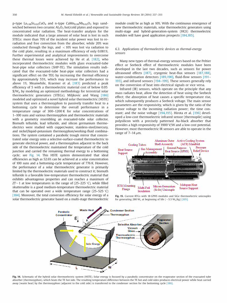
p-type La1.98Sr0.02CuO4 and n-type CaMn0.98Nb0.02O3 legs sand-wiched between two ceramic Al2O3 hot/cold plates and exposed toconcentrated solar radiation. The heat-transfer analysis for themodule indicated that a large amount of solar heat is lost in suchSTEGs: more than 70% of the incident solar power was lost to re-radiation and free convection from the absorber, while 20% wasconducted through the legs, and o10% was lost via radiation tothe cold plate, resulting in a maximum efficiency of only 0.081%.Further experimental and analytical improvements to overcomethese thermal losses were achieved by He et al. [182], whoincorporated thermoelectric modules with glass evacuated-tubeheat-pipe solar collectors (SHP-TE). The simulation results indi-cated that the evacuated-tube heat-pipe solar collectors had asignificant effect on the TEG by increasing the thermal efficiencyby approximately 55%, which may increase the performance toabove 1%. Meanwhile, Kraemer et al. [183] predicted a peakefficiency of 5 with a thermoelectric material cost of below 0.05$/Wp by modeling an optimized methodology for terrestrial solarthermoelectric generators (STEGs). Miljkovic and Wang [186]modeled and optimized a novel hybrid solar thermoelectric (HSTE)system that uses a thermosyphon to passively transfer heat to abottoming cycle to determine the overall performance in atemperature range of 300–1200 K for solar concentrations of1–100 suns and various thermosyphon and thermoelectric materialswith a geometry resembling an evacuated-tube solar collector.Bismuth telluride, lead telluride, and silicon germanium thermo-electrics were studied with copper/water, stainless-steel/mercury,and nickel/liquid-potassium thermosyphon/working-fluid combina-tions. The system contained a parabolic trough mirror that concen-trated solar energy onto a selective-surface-coated thermoelectric togenerate electrical power, and a thermosyphon adjacent to the backside of the thermoelectric maintained the temperature of the coldjunction and carried the remaining thermal energy to a bottomingcycle; see Fig. 14. This HSTE system demonstrated that idealefficiencies as high as 52.6% can be achieved at a solar concentrationof 100 suns and a bottoming-cycle temperature of 776 K. However,the performance of a solar thermoelectric generator is primarilylimited by the thermoelectric materials used to construct it; bismuthtelluride is a favorable low-temperature thermoelectric material thatexhibits advantageous properties and can reaches a maximum ofZT�1 at low temperatures in the range of (25–225 1C), while filledskutterudite is a good medium-temperature thermoelectric materialthat can be operated over a wide temperature range (25–525 1C)[184]. Moreover, the total conversion efficiency for solar energy of asolar thermoelectric generator based on a multi-stage thermoelectric
module could be as high as 10%. With the continuous emergence ofnew thermoelectric materials, solar thermoelectric generators usingmulti-stage and hybrid-generation-system (HGS) thermoelectricmodules will have good application prospects [184,185].
6.3. Applications of thermoelectric devices as thermal-energysensors
Many new types of thermal-energy sensors based on the Peltiereffect or Seebeck effect of thermoelectric modules have beendeveloped in the last two decades, such as sensors for powerultrasound effects [187], cryogenic heat-flux sensors [187,188],water-condensation detectors [189,190], fluid-flow sensors [191–193], and infrared sensors [194–199]. These sensors generally relyon the conversion of heat into electrical signals or vice versa.
Infrared (IR) sensors, which operate on the principle that anymass radiates heat, allow the detection of heat using the Seebeckeffect; the absorption of heat causes a specific temperature rise,which subsequently produces a Seebeck voltage. The main sensorparameters are the responsivity, which is given by the ratio of thesensor voltage to the incoming radiation power; the time con-stant; and the noise voltage [194,195]. Hirota et al. [196] devel-oped a low-cost thermoelectric infrared sensor (thermopile) usingpolysilicon with a precisely patterned Au-black absorber thatprovides a high responsivity of 3900 V/W and a low cost potential.However, most thermoelectric IR sensors are able to operate in therange of 7–14 μm.
Fig. 14. Schematic of the hybrid solar thermoelectric system (HSTE). Solar energy is focused by a parabolic concentrator on the evaporator section of the evacuated tubeabsorber (thermosyphon), which heats the TE hot side. The resulting temperature difference between the TE hot and cold sides produces electrical power while heat carriedaway (waste heat) by the thermosyphon (adjacent to the cold side) is transferred to the condenser section for the bottoming cycle [186].
Fig. 15. Current RTGs with 18 GPHS modules and SiGe thermoelectric unicouplesfor generating 280 We at beginning of life (�5.5 We/kg) [205].
M. Hamid Elsheikh et al. / Renewable and Sustainable Energy Reviews 30 (2014) 337–355350
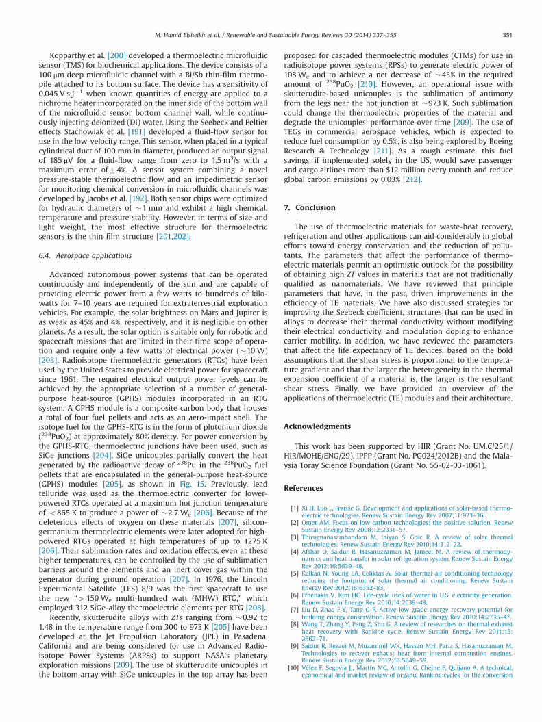
Kopparthy et al. [200] developed a thermoelectric microfluidicsensor (TMS) for biochemical applications. The device consists of a100 μm deep microfluidic channel with a Bi/Sb thin-film thermo-pile attached to its bottom surface. The device has a sensitivity of0.045 V s J�1 when known quantities of energy are applied to anichrome heater incorporated on the inner side of the bottomwallof the microfluidic sensor bottom channel wall, while continu-ously injecting deionized (DI) water. Using the Seebeck and Peltiereffects Stachowiak et al. [191] developed a fluid-flow sensor foruse in the low-velocity range. This sensor, when placed in a typicalcylindrical duct of 100 mm in diameter, produced an output signalof 185 μV for a fluid-flow range from zero to 1.5 m3/s with amaximum error of74%. A sensor system combining a novelpressure-stable thermoelectric flow and an impedimetric sensorfor monitoring chemical conversion in microfluidic channels wasdeveloped by Jacobs et al. [192]. Both sensor chips were optimizedfor hydraulic diameters of �1 mm and exhibit a high chemical,temperature and pressure stability. However, in terms of size andlight weight, the most effective structure for thermoelectricsensors is the thin-film structure [201,202].
6.4. Aerospace applications
Advanced autonomous power systems that can be operatedcontinuously and independently of the sun and are capable ofproviding electric power from a few watts to hundreds of kilo-watts for 7–10 years are required for extraterrestrial explorationvehicles. For example, the solar brightness on Mars and Jupiter isas weak as 45% and 4%, respectively, and it is negligible on otherplanets. As a result, the solar option is suitable only for robotic andspacecraft missions that are limited in their time scope of opera-tion and require only a few watts of electrical power (�10 W)[203]. Radioisotope thermoelectric generators (RTGs) have beenused by the United States to provide electrical power for spacecraftsince 1961. The required electrical output power levels can beachieved by the appropriate selection of a number of general-purpose heat-source (GPHS) modules incorporated in an RTGsystem. A GPHS module is a composite carbon body that housesa total of four fuel pellets and acts as an aero-impact shell. Theisotope fuel for the GPHS-RTG is in the form of plutonium dioxide(238PuO2) at approximately 80% density. For power conversion bythe GPHS-RTG, thermoelectric junctions have been used, such asSiGe junctions [204]. SiGe unicouples partially convert the heatgenerated by the radioactive decay of 238Pu in the 238PuO2 fuelpellets that are encapsulated in the general-purpose heat-source(GPHS) modules [205], as shown in Fig. 15. Previously, leadtelluride was used as the thermoelectric converter for lower-powered RTGs operated at a maximum hot junction temperatureof o865 K to produce a power of �2.7 We [206]. Because of thedeleterious effects of oxygen on these materials [207], silicon-germanium thermoelectric elements were later adopted for high-powered RTGs operated at high temperatures of up to 1275 K[206]. Their sublimation rates and oxidation effects, even at thesehigher temperatures, can be controlled by the use of sublimationbarriers around the elements and an inert cover gas within thegenerator during ground operation [207]. In 1976, the LincolnExperimental Satellite (LES) 8/9 was the first spacecraft to usethe new “4150 We multi-hundred watt (MHW) RTG,” whichemployed 312 SiGe-alloy thermoelectric elements per RTG [208].
Recently, skutterudite alloys with ZTs ranging from �0.92 to1.48 in the temperature range from 300 to 973 K [205] have beendeveloped at the Jet Propulsion Laboratory (JPL) in Pasadena,California and are being considered for use in Advanced Radio-isotope Power Systems (ARPSs) to support NASA's planetaryexploration missions [209]. The use of skutterudite unicouples inthe bottom array with SiGe unicouples in the top array has been
proposed for cascaded thermoelectric modules (CTMs) for use inradioisotope power systems (RPSs) to generate electric power of108 We and to achieve a net decrease of �43% in the requiredamount of 238PuO2 [210]. However, an operational issue withskutterudite-based unicouples is the sublimation of antimonyfrom the legs near the hot junction at �973 K. Such sublimationcould change the thermoelectric properties of the material anddegrade the unicouples' performance over time [209]. The use ofTEGs in commercial aerospace vehicles, which is expected toreduce fuel consumption by 0.5%, is also being explored by BoeingResearch & Technology [211]. As a rough estimate, this fuelsavings, if implemented solely in the US, would save passengerand cargo airlines more than $12 million every month and reduceglobal carbon emissions by 0.03% [212].
7. Conclusion
The use of thermoelectric materials for waste-heat recovery,refrigeration and other applications can aid considerably in globalefforts toward energy conservation and the reduction of pollu-tants. The parameters that affect the performance of thermo-electric materials permit an optimistic outlook for the possibilityof obtaining high ZT values in materials that are not traditionallyqualified as nanomaterials. We have reviewed that principleparameters that have, in the past, driven improvements in theefficiency of TE materials. We have also discussed strategies forimproving the Seebeck coefficient, structures that can be used inalloys to decrease their thermal conductivity without modifyingtheir electrical conductivity, and modulation doping to enhancecarrier mobility. In addition, we have reviewed the parametersthat affect the life expectancy of TE devices, based on the boldassumptions that the shear stress is proportional to the tempera-ture gradient and that the larger the heterogeneity in the thermalexpansion coefficient of a material is, the larger is the resultantshear stress. Finally, we have provided an overview of theapplications of thermoelectric (TE) modules and their architecture.
Acknowledgments
This work has been supported by HIR (Grant No. UM.C/25/1/HIR/MOHE/ENG/29), IPPP (Grant No. PG024/2012B) and the Mala-ysia Toray Science Foundation (Grant No. 55-02-03-1061).
References
[1] Xi H, Luo L, Fraisse G. Development and applications of solar-based thermo-electric technologies. Renew Sustain Energy Rev 2007;11:923–36.
[2] Omer AM. Focus on low carbon technologies: the positive solution. RenewSustain Energy Rev 2008;12:2331–57.
[3] Thirugnanasambandam M, Iniyan S, Goic R. A review of solar thermaltechnologies. Renew Sustain Energy Rev 2010;14:312–22.
[4] Afshar O, Saidur R, Hasanuzzaman M, Jameel M. A review of thermody-namics and heat transfer in solar refrigeration system. Renew Sustain EnergyRev 2012;16:5639–48.
[5] Kalkan N, Young EA, Celiktas A. Solar thermal air conditioning technologyreducing the footprint of solar thermal air conditioning. Renew SustainEnergy Rev 2012;16:6352–83.
[6] Fthenakis V, Kim HC. Life-cycle uses of water in U.S. electricity generation.Renew Sustain Energy Rev 2010;14:2039–48.
[7] Liu D, Zhao F-Y, Tang G-F. Active low-grade energy recovery potential forbuilding energy conservation. Renew Sustain Energy Rev 2010;14:2736–47.
[8] Wang T, Zhang Y, Peng Z, Shu G. A review of researches on thermal exhaustheat recovery with Rankine cycle. Renew Sustain Energy Rev 2011;15:2862–71.
[9] Saidur R, Rezaei M, Muzammil WK, Hassan MH, Paria S, Hasanuzzaman M.Technologies to recover exhaust heat from internal combustion engines.Renew Sustain Energy Rev 2012;16:5649–59.
[10] Vélez F, Segovia JJ, Martín MC, Antolín G, Chejne F, Quijano A. A technical,economical and market review of organic Rankine cycles for the conversion
M. Hamid Elsheikh et al. / Renewable and Sustainable Energy Reviews 30 (2014) 337–355 351
of low-grade heat for power generation. Renew Sustain Energy Rev2012;16:4175–89.
[11] Martín-González M, Caballero-Calero O, Díaz-Chao P. Nanoengineeringthermoelectrics for 21st century: energy harvesting and other trends inthe field. Renew Sustain Energy Rev 2013;24:288–305.
[12] Shu G, Liang Y, Wei H, Tian H, Zhao J, Liu L. A review of waste heat recoveryon two-stroke IC engine aboard ships. Renew Sustain Energy Rev2013;19:385–401.
[13] Riffat SB, Ma X. Thermoelectrics: a review of present and potential applica-tions. Appl Therm Eng 2003;23:913–35.
[14] Dai D, Zhou Y, Liu J. Liquid metal based thermoelectric generation system forwaste heat recovery. Renew Energy 2011;36:3530–6.
[15] Tie SF, Tan CW. A review of energy sources and energy management systemin electric vehicles. Renew Sustain Energy Rev 2013;20:82–102.
[16] Ullah KR, Saidur R, Ping HW, Akikur RK, Shuvo NH. A review of solar thermalrefrigeration and cooling methods. Renew Sustain Energy Rev 2013;24:499–513.
[17] Tsubota T, Ohno T, Shiraishi N, Miyazaki Y. Thermoelectric properties ofSn1�x�yTiySbxO2 ceramics. J Alloys Compd 2008;463:288–93.
[18] Pichanusakorn P, Bandaru P. Nanostructured thermoelectrics. Mater Sci EngR: Rep 2010;67:19–63.
[19] Gao X, Uehara K, Klug DD, Tse JS. Rational design of high-efficiencythermoelectric materials with low band gap conductive polymers. ComputMater Sci 2006;36:49–53.
[20] Zhan G-D, Kuntz JD, Mukherjee AK, Zhu P, Koumoto K. Thermoelectricproperties of carbon nanotube/ceramic nanocomposites. Scr Mater2006;54:77–82.
[21] Snyder GJ, Toberer ES. Complex thermoelectric materials. Nat Mater2008;7:105–14.
[22] Cai KF, Mueller E, Drasar C, Stiewe C. The effect of titanium diboride additionon the thermoelectric properties of β-FeSi2 semiconductors. Solid StateCommun 2004;131:325–9.
[23] Zide J, Vashaee D, Bian Z, Zeng G, Bowers J, Shakouri A, et al. Demonstrationof electron filtering to increase the Seebeck coefficient in In0.53Ga0.47As∕In0.53Ga0.28Al0.19As superlattices. Phys Rev B 2006:74.
[24] Bian Z, Shakouri A. Enhanced solid-state thermionic emission in nonplanarheterostructures. Appl Phys Lett 2006;88:012102.
[25] Zheng J-C. Recent advances on thermoelectric materials. Front Phys China2008;3:269–79.
[26] Hochbaum AI, Chen R, Delgado RD, Liang W, Garnett EC, Najarian M, et al.Enhanced thermoelectric performance of rough silicon nanowires. Nature2008;451:163–7.
[27] Venkatasubramanian R, Siivola E, Colpitts T, O'Quinn B. Thin-film thermo-electric devices with high room-temperature figures of merit. Nature2001;413:597–602.
[28] Harman TC, Taylor PJ, Walsh MP, LaForge BE. Quantum dot superlatticethermoelectric materials and devices. Science 2002;297:2229–32.
[29] Sootsman JR, Chung DY, Kanatzidis MG. New and old concepts in thermo-electric materials. Angew Chem Int Ed 2009;48:8616–39.
[30] Nolas GS, Morelli DT, Tritt TM. KUTTERUDITES: a phonon-glass-electroncrystal approach to advanced thermoelectric energy conversion applications.Annu Rev Mater Sci 1999;29:89–116.
[31] HERWAARDEN VAN, SARRO AW, THERMAL PM. Sensors based on theseebeck effect. Sensors Actuat A: Phys 1986;10:321–46.
[32] Tritt TM, Subramanian MA. Thermoelectric materials, phenomena, andapplications: a bird's eye view. MRS Bull 2006;31:188–229.
[33] Pereira Gonçalves A, Branco Lopes E, Rouleau O, Godart C. Conducting glassesas new potential thermoelectric materials: the Cu–Ge–Te case. J Mater Chem2010;20:1516.
[34] Dmitriev AV, Zvyagin IP. Current trends in the physics of thermoelectricmaterials. Physics – Uspekhi 2010;53:789–803.
[35] Wan C, Wang Y, Wang N, Koumoto K. Low-thermal-conductivity(MS)1þx(TiS2)2 (M¼Pb, Bi, Sn) misfit layer compounds for bulk thermo-electric materials. Materials 2010;3:2606–17.
[36] Bulusu A, Walker DG. Review of electronic transport models for thermo-electric materials. Superlattices Microstruct. 2008;44:1–36.
[37] Ma Y, Hao Q, Poudel B, Lan Y, Yu B, Wang D, et al. Enhanced thermoelectricfigure-of-merit in p-type nanostructured bismuth antimony tellurium alloysmade from elemental chunks. Nano Lett. 2008;8:2580–4.
[38] Gonçalves AP, Lopes EB, Delaizir G, Vaney JB, Lenoir B, Piarristeguy A, et al.Semiconducting glasses: a new class of thermoelectric materials? J. SolidState Chem. 2012;193:26–30.
[39] Joshi G, Lee H, Lan Y, Wang X, Zhu G, Wang D, et al. Enhanced thermo-electric figure-of-merit in nanostructured p-type silicon germanium bulkalloys. Nano Lett. 2008;8:4670.
[40] Cadoff IB, Miller E. Thermoelecteric materials and devices. New York:Reinhold Publishing Corporation; 1960.
[41] Das VD, Ganesan PG. Thickness and temperature effects on thermoelectricpower and electrical resistivity of (Bi0.25Sb0.75)2Te3 thin films. Mater ChemPhys 1998;57:57–66.
[42] Kowalczyk A, Falkowski M, Toliński T, Tran VH, Miiller W, Reiffers M, et al.Specific heat, electrical resistivity and thermoelectric power of YbNi4Si.Mater Res Bull 2008;43:185–90.
[43] Wang YF, Lee KH, Ohta H, Koumoto K. Fabrication and thermoelectricproperties of heavily rare-earth metal-doped SrO(SrTiO3)n (n¼1, 2) ceramics.Ceram Int 2008;34:849–52.
[44] Watanabe N, Nakayama H, Fukao F, Munakata F. Effects of metal substitutionon the electric and thermoelectric properties in (Ni1�xMx)Mn2O4 (M¼Znand Mg). Thermochim Acta 2012;532:56–9.
[45] Iversen BB, Palmqvist AEC, Cox DE, Nolas GS, Stucky GD, Blake NP, et al. Whyare clathrates good candidates for thermoelectric materials? J Solid StateChem 2000;149:455–8.
[46] Kleinke H. New bulk materials for thermoelectric power generation: clath-rates and complex antimonides†. Chem Mater 2010;22:604–11.
[47] Christensen M, Juranyi F, Iversen BB. The rattler effect in thermoelectricclathrates studied by inelastic neutron scattering. Physica B: CondensedMatter 2006;385-386:505–7.
[48] Anno H, Yamada H, Nakabayashi T, Hokazono M, Shirataki R. Galliumcomposition dependence of crystallographic and thermoelectric propertiesin polycrystalline type-I Ba8GaxSi46�x (nominal x¼14–18) clathrates pre-pared by combining arc melting and spark plasma sintering methods. J SolidState Chem 2012;193:94–104.
[49] Kim SW, Kimura Y, Mishima Y. Effects of doping on the high-temperaturethermoelectric properties of IrSb3 skutterudite compounds. J Electron Mater2003;32:1141–7.
[50] Vaqueiro P, Sobany GG, Powell AV, Knight KS. Structure and thermoelectricproperties of the ordered skutterudite CoGe1.5Te1.5. J Solid State Chem2006;179:2047–53.
[51] Kim IH, Park KH, Ur SC. Thermoelectric properties of Sn-doped CoSb3prepared by encapsulated induction melting. J Alloys Compd 2007;442:351–4.
[52] Ur S-C, Kwon J-C, Kim I-H. Thermoelectric properties of Fe-doped CoSb3prepared by mechanical alloying and vacuum hot pressing. J Alloys Compd2007;442:358–61.
[53] Alboni PN, Ji X, He J, Gothard N, Hubbard J, Tritt TM. Synthesis andthermoelectric properties of nano-engineered CoSb3 skutterudite materials.J Electron Mater 2007;36:711–5.
[54] Matsuoka E, Morimoto S, Tanaka K, Sasakawa T, Takabatake T. Magnetic andthermoelectric properties of BayFe4�xCoxSb12. Physica B: Condensed Matter2006;383:132–3.
[55] Park K-H, Kim I-H. Thermoelectric properties of Ca-filled CoSb3-basedskutterudites synthesized by mechanical alloying. J Electron Mater 2010;40:493–8.
[56] Kim SW, Kimura Y, Mishima Y. Effect of partial La filling on high-temperature thermoelectric properties of IrSb3-based skutterudite com-pounds. J Electron Mater 2004;33:1156–60.
[57] Alleno E, Bérardan D, Godart C, Puyet M, Lenoir B, Lackner R, et al. Doublefilling in skutterudites: a promising path to improved thermoelectric proper-ties. Physica B: Condensed Matter 2006;383:103–6.
[58] Sklad AC, Gaultois MW, Grosvenor AP. Examination of CeFe4Sb12 uponexposure to air: is this material appropriate for use in terrestrial, high-temperature thermoelectric devices? J Alloys Compd, 505; 2010; L6–9.
[59] Rogl G, Grytsiv A, Rogl P, Bauer E, Zehetbauer M. A new generation of p-typedidymium skutterudites with high ZT. Intermetallics 2011;19:546–55.
[60] Grytsiv A, Rogl P, Berger S, Paul C, Michor H, Bauer E, et al. Novelthermoelectric skutterudites SnyNi4Sb12�xSnx. Physica B: Condensed Matter2003;328:71–3.
[61] Jung J-Y, Ur S-C, Kim I-H. Thermoelectric properties of InzCo4Sb12�yTeyskutterudites. Mater Chem Phys 2008;108:431–4.
[62] Lu P-X, Wu F, Han H-L, Wang Q, Shen Z-G, Hu X. Thermoelectric properties ofrare earths filled CoSb3 based nanostructure skutterudite. J Alloys Compd2010;505:255–8.
[63] Liu K, Dong X, Jiuxing Z. The effects of La on thermoelectric properties ofLaxCo4Sb12 prepared by MA–SPS. Mater Chem Phys 2006;96:371–5.
[64] Ravot D, Lafont U, Chapon L, Tedenac JC, Mauger A. Anomalous physicalproperties of cerium–lanthanum filled skutterudites. J Alloys Compd2001;323–324:389–91.
[65] Bai SQ, Pei YZ, Chen LD, Zhang WQ, Zhao XY, Yang J. Enhanced thermo-electric performance of dual-element-filled skutterudites BaxCeyCo4Sb12.Acta Mater 2009;57:3135–9.
[66] Ballikaya S, Uzar N, Yildirim S, Salvador JR, Uher C. High thermoelectricperformance of In, Yb, Ce multiple filled CoSb3 based skutterudite com-pounds. J Solid State Chem 2012;193:31–5.
[67] Chakoumakos BC, Sales BC. Skutterudites: their structural response to filling.J Alloys Compd 2006;407:87–93.
[68] Deng L, Jia XP, Su TC, Jiang YP, Zheng SZ, Guo X, et al. The thermoelectricproperties of Co4Sb12-xTex synthesized at different pressure. Mater Lett2011;65:1057–9.
[69] Wojciechowski KT, Toboła J, Leszczyński J. Thermoelectric properties andelectronic structure of CoSb3 doped with Se and Te. J Alloys Compd2003;361:19–27.
[70] Kitagawa H, Wakatsuki M, Nagaoka H, Noguchi H, Isoda Y, Hasezaki K, et al.Temperature dependence of thermoelectric properties of Ni-doped CoSb3. JPhys Chem Solids 2005;66:1635–9.
[71] Peng J, Yang J, Zhang T, Song X, Chen Y. Preparation and characterization ofFe substituted CoSb3 skutterudite by mechanical alloying and annealing. JAlloys Compd 2004;381:313–6.
[72] Yu J, Zhao W, Zhou H, Wei P, Zhang Q. Rapid preparation and thermoelectricproperties of Ba and In double-filled p-type skutterudite bulk materials. ScrMater 2013;68:643–6.
[73] Shi X, Salvador JR, Yang J, Wang H. Thermoelectric properties of n-typemultiple-filled Skutterudites. J Electron Mater 2009;38:930–3.
M. Hamid Elsheikh et al. / Renewable and Sustainable Energy Reviews 30 (2014) 337–355352
[74] Shi X, Yang J, Salvador JR, Chi M, Cho JY, Wang H, et al. Multiple-filledskutterudites: high thermoelectric figure of merit through separately opti-mizing electrical and thermal transports. J Am Chem Soc 2011;133:7837–46.
[75] Zou M, Li J-F, Kita T. Thermoelectric properties of fine-grained FeVSb half-Heusler alloys tuned to p-type by substituting vanadium with titanium. JSolid State Chem 2013;198:125–30.
[76] Wang S-H, Cheng H-M, Wu R-J, Chao W-H. Structural and thermoelectricproperties of HfNiSn half-Heusler thin films. Thin Solid Films 2010;518:5901–4.
[77] Kawaharada Y, Kurosaki K, Muta H, Uno M, Yamanaka S. High temperaturethermoelectric properties of CoNb1�xHfxSn1�ySby half-Heusler compounds. JAlloys Compd 2004;377:312–5.
[78] Shutoh N, Sakurada S. Thermoelectric properties of the TiX(Zr0.5Hf0.5)1�xNiSnhalf-Heusler compounds. J Alloys Compd 2005;389:204–8.
[79] Lee P-J, Chao L-S. High-temperature thermoelectric properties of Ti0.5(ZrHf)0.5�xNbxNi0.9Pd0.1Sn0.98Sb0.02 half-Heusler alloys. J Alloys Compd2010;504:192–6.
[80] Fu C, Xie H, Liu Y, Zhu TJ, Xie J, Zhao XB. Thermoelectric properties of FeVSbhalf-Heusler compounds by levitation melting and spark plasma sintering.Intermetallics 2013;32:39–43.
[81] Maji P, Takas NJ, Misra DK, Gabrisch H, Stokes K, Poudeu PFP. Effects of Rh onthe thermoelectric performance of the p-type Zr0.5Hf0.5Co1�xRhxSb0.99Sn0.01
half-Heusler alloys. J Solid State Chem 2010;183:1120–6.[82] Nylén J, Lidin S, Andersson M, Liu H, Newman N, Häussermann U. Effect of
metal doping on the low-temperature structural behavior of thermoelectricβ-Zn4Sb3. J Solid State Chem 2007;180:2603–15.
[83] Carreon H. On the exploitation of thermoelectric coupling for characteriza-tion of elliptical inclusions in metals. Expl Therm Fluid Sci 2013;44:673–9.
[84] Ferreira NM, Rasekh S, Costa FM, Madre MA, Sotelo A, Diez JC, et al. Newmethod to improve the grain alignment and performance of thermoelectricceramics. Mater Lett 2012;83:144–7.
[85] Liu S, Wang J, Jia J, Hu X, Liu S. Synthesis and thermoelectric performance ofLi-doped NiO ceramics. Ceram Int 2012;38:5023–6.
[86] Wang HC, Wang CL, Su WB, Liu J, Zhao Y, Peng H, et al. Enhancement ofthermoelectric figure of merit by doping Dy in La0.1Sr0.9TiO3 ceramic.Mater Res Bull 2010;45:809–12.
[87] Constantinescu G, Rasekh S, Torres MA, Madre MA, Diez JC, Sotelo A.Enhancement of the high-temperature thermoelectric performance ofBi2Ba2Co2Ox ceramics. Scr Mater 2013;68:75–8.
[88] Kenfaui D, Chateigner D, Gomina M, Noudem JG. Texture mechanical andthermoelectric properties of Ca3Co4O9 ceramics. J Alloys Compd 2010;490:472–9.
[89] Li F, Li J-F. Effect of Ni substitution on electrical and thermoelectric proper-ties of LaCoO3 ceramics. Ceram Int 2011;37:105–10.
[90] Liu J, Wang CL, Su WB, Wang HC, Li JC, Zhang JL, et al. Thermoelectricproperties of Sr1�xNdxTiO3 ceramics. J Alloys Compd 2010;492:L54–6.
[91] Tajima S, Tani T, Isobe S, Koumoto K. Thermoelectric properties of highlytextured NaCo2O4 ceramics processed by the reactive templated graingrowth (RTGG) method. Mater Sci Eng 2001;B86:20–5.
[92] Wang LM, Chang C-Y, Yeh S-T, Chen SW, Peng ZA, Bair SC, et al. Synthesisand post-annealing effects on the transport properties of thermoelectricoxide (ZnO)mIn2O3 ceramics. Ceram Int 2012;38:1167–74.
[93] Yasukawa M, Kono T. Preparation of dense BaPbO3-based ceramics by acoprecipitation and their thermoelectric properties. J Alloys Compd2006;426:420–5.
[94] Yasukawa M, Kono T, Ueda K, Yanagi H, Hosono H. High-temperaturethermoelectric properties of La-doped BaSnO3 ceramics. Mater Sci Eng B2010;173:29–32.
[95] Wang N, He H, Li X, Han L, Zhang C. Enhanced thermoelectric properties ofNb-doped SrTiO3 polycrystalline ceramic by titanate nanotube addition. JAlloys Compd 2010;506:293–6.
[96] Delorme F, Martin CF, Marudhachalam P, Ovono DO, Guzman G. Effect of Casubstitution by Sr on the thermoelectric properties of Ca3Co4O9 Ceramics. JAlloys Compd 2011;509:2311–5.
[97] Noudem JG, Lemonnier S, Prevel M, Reddy ES, Guilmeau E, Goupil C.Thermoelectric ceramics for generators. J Eur Ceram Soc 2008;28:41–8.
[98] Tsai T-C, Chang H-C, Chen C-H, Whang W-T. Widely variable Seebeckcoefficient and enhanced thermoelectric power of PEDOT:PSS films byblending thermal decomposable ammonium formate. Org Electron2011;12:2159–64.
[99] Choi Y, Kim Y, Park S-G, Kim Y-G, Sung BJ, Jang S-Y, et al. Effect of the carbonnanotube type on the thermoelectric properties of CNT/Nafion nanocompo-sites. Org Electron 2011;12:2120–5.
[100] Yue R, Xu J. Poly(3,4-ethylenedioxythiophene) as promising organic thermo-electric materials: a mini-review. Synth Met 2012;162:912–7.
[101] Chatterjee K, Suresh A, Ganguly S, Kargupta K, Banerjee D. Synthesis andcharacterization of an electro-deposited polyaniline-bismuth telluride nano-composite — a novel thermoelectric material. Mater Charact 2009;60:1597–601.
[102] Du Y, Shen SZ, Cai K, Casey PS. Research progress on polymer–inorganicthermoelectric nanocomposite materials. Prog Polym Sci 2012;37:820–41.
[103] Zhang KX, Qin XY, Xin HX, Li HJ, Zhang J. Transport and thermoelectricproperties of nanocrystal substitutional semiconductor alloys(Mg1�xCdx)3Sb2 doped with Ag. J Alloys Compd 2009;484:498–504.
[104] Chen L, Li J, Sun F, Wu C. Performance optimization of a two-stagesemiconductor thermoelectric-generator. Appl Energy 2005;82:300–12.
[105] Dughaish ZH. Lead telluride as a thermoelectric material for thermoelectricpower generation. Physica B 2005;322:205–23.
[106] Majumdar A. Thermoelectricity in semiconductor nanostructures. Mater Sci2004;303:777–8.
[107] Alam H, Ramakrishna S. A review on the enhancement of figure of merit frombulk to nano-thermoelectric materials. Nano Energy 2013;2:190–212.
[108] Tani J-i Kido H. Thermoelectric properties of Bi-doped Mg2Si semiconductors.Physica B: Condensed Matter 2005;364:218–24.
[109] Ozpineci B, Tolbert LM. Comparison of wide-bandgap semiconductors forpower electronics applications. Oak Ridge National Laboratory; 2003.
[110] Omar MS, Gorges FY. The optical energy gap dependence on both carrierconcentration and intrinsic energy gap in n-type semiconductors. Mater SciSemiconduct Process 2006;9:164–7.
[111] Gao Y, Ying P, Cui J, Chen S, Li Y. Thermoelectric properties of Cu and Sb Co-doped Ga-Te based semiconductor with wide band gap. Proc Eng 2012;27:156–62.
[112] Hummel RE. Electronic properties of materials. 3rd edition. New York:Springer; 2011.
[113] Nag BR. Direct band-gap energy of semiconductors. Infrared Phys Technol1995;36:831–5.
[114] Zhang FP, Lu QM, Zhang X, Zhang JX. First principle investigation of electronicstructure of CaMnO3 thermoelectric compound oxide. J Alloys Compd2011;509:542–5.
[115] Ramdas AK, Rodriguez S, Tsoi S, Haller EE. Electronic band gaps of semi-conductors as influenced by their isotopic composition. Solid State Commun2005;133:709–14.
[116] Tan G, Wang S, Yan Y, Li H, Tang X. Enhanced thermoelectric performance inp-type Ca0.5Ce0.5Fe4�xNixSb12 skutterudites by adjusting the carrier concen-tration. J Alloys Compd 2012;513:328–33.
[117] Wang S, Fu F, She X, Zheng G, Li H, Tang X. Optimizing thermoelectricperformance of Cd-doped β-Zn4Sb3 through self-adjusting carrier concen-tration. Intermetallics 2011;19:1823–30.
[118] Delaizir G, Bernard-Granger G, Monnier J, Grodzki R, Kim-Hak O, Szkutnik PD,et al. A comparative study of Spark Plasma Sintering (SPS), Hot IsostaticPressing (HIP) and microwaves sintering techniques on p-type Bi2Te3thermoelectric properties. Mater Res Bull 2012;47:1954–60.
[119] Drasar C, Kucek V, Benes L, Lostak P, Vlcek Mb. Thermoelectric properties andnonstoichiometry of GaGeTe. J Solid State Chem 2012;193:42–6.
[120] Roudebush JH, Toberer ES, Hope H, Jeffrey Snyder G, Kauzlarich SM. Crystalstructure, characterization and thermoelectric properties of the type-Iclathrate Ba8�ySryAl14Si32 (0.6ryr1.3) prepared by aluminum flux. J SolidState Chem 2011;184:1176–85.
[121] Mikhnovich Jr. VV. Scattering of charge carriers in semiconductors: modelsand their criteria. Physica 2001;B 308–310:1023–6.
[122] Karl N. Charge carrier transport in organic semiconductors. Synth Met2003;133–134:649–57.
[123] Uberuaga BP, Henkelman G, Jo´nsson H, Dunham ST, Windl W, Stumpf R.Theoretical studies of self-diffusion and dopant clustering in semiconductors.Phys stat sol 2002;233:24–30.
[124] Bracht HA, Silvestri HH, Haller EE. Advanced diffusion studies with isotopi-cally controlled materials. Solid State Commun 2005;133:727–35.
[125] Cui JL, Zhao XB, Zhao WM, Lu YP. Preparation, thermoelectric properties andinterface analysis of n-type graded material FeSi2/Bi2Te3. Mater Sci Eng 2002;B94:223–8.
[126] Nakagawa T, Sakaguchi I, Matsunaga K, Yamamoto T, Haneda H,Ikuhara Y. Control of point defects and grain boundaries in advancedmaterials. Nucl Inst Meth Phys Res Sect B: Beam Inter Mater Atoms2005;232:343–7.
[127] Wanwan L, Zechun C, Bin Z, Feng Z, Hongtao L, Wenbin S, et al. Study on theeffect of Cd-diffusion annealing on the electrical properties of CdZnTe. JCrystal Growth 2006;292:53–61.
[128] Bae N-H, Han S, Lee KE, Kim B, Kim S-T. Diffusion at interfaces of microthermoelectric devices. Curr Appl Phys 2011;11:S40–4.
[129] Xu Z, Lan Z, Zhu G, Sun K, Yu Z. Effects of the oxygen partial pressure duringdeposition on the material characteristics and magnetic properties of BaMthin films. J Alloys Compd 2012;538:11–5.
[130] Terasaki I. Transport properties and electronic states of the thermoelectricoxide NaCo2O4. Physica B: Condensed Matter 2003;328:63–7.
[131] Ito M, Furumoto D. Effects of noble metal addition on microstructure andthermoelectric properties of NaxCo2O4. J Alloys Compd 2008;450:494–8.
[132] Zhou XF, Zhang H, Chen QM, Shang J, Zhang PX. Effects of annealingatmosphere on thermoelectric signals from ZnO films. Thin Solid Films2011;519:3026–8.
[133] Li FM, Waddingham R, Milne WI, Flewitt AJ, Speakman S, Dutson J, et al. Lowtemperature (o100 1C) deposited P-type cuprous oxide thin films: impor-tance of controlled oxygen and deposition energy. Thin Solid Films2011;520:1278–84.
[134] Liu HJ, Song CM, Wu ST, Li LF. Processing method dependency of thermo-electric properties of Bi85Sb15 alloys in low temperature. Cryogenics2007;47:56–60.
[135] Prokhorov VM, Pivovarov GI. Detection of internal cracks and ultrasoundcharacterization of nanostructured Bi2Te3-based thermoelectrics via acousticmicroscopy. Ultrasonics 2011;51:715–8.
[136] Moon C, Shin S, Kim D, Kim T-S. Microstructure and thermoelectric proper-ties of p-type Bi2Te3–Sb2Te3 alloys produced by rapid solidification andspark plasma sintering. J Alloys Compd 2010;504:S504–7.
M. Hamid Elsheikh et al. / Renewable and Sustainable Energy Reviews 30 (2014) 337–355 353

[137] Kim T-S, Chun B-S. Microstructure and thermoelectric properties of n- and p-typeBi2Te3 alloys by rapid solidification processes. J Alloys Compd 2007;437:225–30.
[138] Ren F, Case ED, Timm EJ, Schock HJ. Hardness as a function of composition forn-type LAST thermoelectric material. J Alloys Compd 2008;455:340–5.
[139] Zhou D, Liu J, Xu S, Peng P. Thermal stability and elastic properties of Mg2X(X¼Si, Ge, Sn, Pb) phases from first-principle calculations. Comput Mater Sci2012;51:409–14.
[140] Fan X, Case ED, Ren F, Shu Y, Baumann MJ, Part II. Fracture strength andelastic modulus as a function of porosity for hydroxyapatite and other brittlematerials. J Mech Behav Biomed Mater 2012;8:99–110.
[141] Hong S-J, Lee S-H, Chun B-S. Thermoelectric properties of newly fabricated n-type 95%Bi2Te2–5%Bi2Se3 alloys by gas atomizing and extrusion process.Mater Sci Eng B 2003;98:232–8.
[142] Zhao D, Li X, He L, Jiang W, Chen L. Interfacial evolution behavior andreliability evaluation of CoSb3/Ti/Mo–Cu thermoelectric joints during accel-erated thermal aging. J Alloys Compd 2009;477:425–31.
[143] Zhao D, Geng H, Teng X. Fabrication and reliability evaluation of CoSb3/W–Cuthermoelectric element. J Alloys Compd 2012;517:198–203.
[144] Zhu T, Li J. Ultra-strength materials. Prog Mater Sci 2010;55:710–57.[145] Jung D-y Kurosaki K, Kim C-e, Muta H, Yamanaka S. Thermal expansion and
melting temperature of the half-Heusler compounds: MNiSn (M¼Ti, Zr, Hf).J Alloys Compd 2010;489:328–31.
[146] Huang M-J, Chou P-K, Lin M-C. Thermal and thermal stress analysis of a thin-film thermoelectric cooler under the influence of the Thomson effect. SensActuat A: Phys 2006;126:122–8.
[147] Al-Merbati AS, Yilbas BS, Sahin AZ. Thermodynamics and thermal stressanalysis of thermoelectric power generator: influence of pin geometry ondevice performance. Appl Therm Eng 2013;50:683–92.
[148] Asenath-Smith E, Misture ST, Edwards DD. Structural behavior and thermo-electric properties of the brownmillerite system Ca2(ZnxFe2�x)O5. J SolidState Chem 2011;184:2167–77.
[149] Tachibana M, Fang J. An estimation of thermal stress of thermoelectricdevices in the temperature cycling test. Proc Eng 2012;27:177–85.
[150] Rogl G, Aabdin Z, Schafler E, Horky J, Setman D, Zehetbauer M, et al. Effect ofHPT processing on the structure, thermoelectric and mechanical propertiesof Sr0.07Ba0.07Yb0.07Co4Sb12. J Alloys Compd 2012;537:183–9.
[151] Ahiska R, Dislitas S, Omer G. A new method and computer-controlled systemfor measuring the time constant of real thermoelectric modules. EnergyConvers Manage 2012;53:314–21.
[152] Chein R, Huang G. Thermoelectric cooler application in electronic cooling.Appl Therm Eng 2004;24:2207–17.
[153] Putra N, Yanuar, Iskandar FN. Application of nanofluids to a heat pipe liquid-block and the thermoelectric cooling of electronic equipment. Exp ThermFluid Sci 2011;35:1274–81.
[154] Zhang HY, Mui YC, Tarin M. Analysis of thermoelectric cooler performancefor high power electronic packages. Appl Therm Eng 2010;30:561–8.
[155] PrezAparicio JL, Palma R, Taylor RL. Finite element analysis and materialsensitivity of Peltier thermoelectric cells coolers. Int J Heat Mass Transf2012;55:1363–74.
[156] Chang Y-W, Chang C-C, Ke M-T, Chen S-L. Thermoelectric air-cooling modulefor electronic devices. Appl Therm Eng 2009;29:2731–7.
[157] Huang H-S, Weng Y-C, Chang Y-W, Chen S-L, Ke M-T. Thermoelectric water-cooling device applied to electronic equipment. Int Commun Heat MassTransf 2010;37:140–6.
[158] Zhou Y, Yu J. Design optimization of thermoelectric cooling systems forapplications in electronic devices. Int J Refrig 2012;35:1139–44.
[159] Wang X, Yu J, Ma M. Optimization of heat sink configuration for thermo-electric cooling system based on entropy generation analysis. Int J Heat MassTransf 2013;63:361–5.
[160] Abdul-Wahab SA, Elkamel A, Al-Damkhi AM, IhA Al-Habsi, Al-Rubai'ey HS,Al-Battashi AK, et al. Design and experimental investigation of portable solarthermoelectric refrigerator. Renew Energy 2009;34:30–4.
[161] Dai YJ, Wang RZ, Ni L. Experimental investigation on a thermoelectricrefrigerator driven by solar cells. Renew Energy 2003;28:949–59.
[162] Chen L, Meng F, Sun F. Effect of heat transfer on the performance ofthermoelectric generator-driven thermoelectric refrigerator system. Cryo-genics 2012;52:58–65.
[163] Luo T, Wang S, Li H, Tang X. Low temperature thermoelectric properties ofmelt spun Bi85Sb15 alloys. Intermetallics 2013;32:96–102.
[164] Meng F, Chen L, Sun F. Performance prediction and irreversibility analysis ofa thermoelectric refrigerator with finned heat exchanger. Acta Phys Pol A2011;120:397–406.
[165] Available at www.tetech.com; 2010.[166] Shen L, Xiao F, Chen H, Wang S. Investigation of a novel thermoelectric
radiant air-conditioning system. Energy Build 2013;59:123–32.[167] Riffat SB, Qiu G. Comparative investigation of thermoelectric air-conditioners
versus vapour compression and absorption air-conditioners. Appl Therm Eng2004;24:1979–93.
[168] Cherkez R. Theoretical studies on the efficiency of air conditioner based onpermeable thermoelectric converter. Appl Therm Eng 2012;38:7–13.
[169] Niu X, Yu J, Wang S. Experimental study on low-temperature waste heatthermoelectric generator. J Power Sources 2009;188:621–6.
[170] Vullers RJM, van Schaijk R, Doms I, Van Hoof C, Mertens R. Micropowerenergy harvesting. Solid-State Electron 2009;53:684–93.
[171] Snyder G.J. Small thermoelectric generators. Interface: the electrochemicalsociety, Fall; 2008. p. 54–6.
[172] Group A-hW. Critical raw materials for the EU. European Commission; 2010.[173] Yu C, Chau KT. Thermoelectric automotive waste heat energy recovery using
maximum power point tracking. Energy Convers Manage 2009;50:1506–12.[174] Hsu C-T, Huang G-Y, Chu H-S, Yu B, Yao D-J. Experiments and simulations on
low-temperature waste heat harvesting system by thermoelectric powergenerators. Appl Energy 2011;88:1291–7.
[175] Karri MA, Thacher EF, Helenbrook BT. Exhaust energy conversion by thermo-electric generator: two case studies. Energy Convers Manage 2011;52:1596–611.
[176] Gou X, Yang S, Xiao H, Ou Q. A dynamic model for thermoelectric generatorapplied in waste heat recovery. Energy 2013;52:201–9.
[177] Yee SK, LeBlanc S, Goodson KE, Dames C. $ per W metrics for thermoelectricpower generation: beyond ZT. Energy Environ Sci 2013;6:2561.
[178] Sano S, Mizukami H, Kaibe H. Development of high-efficiency thermoelectricpower generation system. KOMAT'SU; 2003.
[179] Omer SA, Infield DG. Design optimization of thermoelectric devices for solarpower generation. Solar Energy Mater Solar Cells 1998;53:67–82.
[180] Omer SA, Infield DG. Design and thermal analysis of a two stage solarconcentrator for combined heat and thermoelectric power generation.Energy Convers Manage 2000;41:737–56.
[181] Suter C, Tomeš P, Weidenkaff A, Steinfeld A. Heat transfer and geometricalanalysis of thermoelectric converters driven by concentrated solar radiation.Materials 2010;3:2735–52.
[182] He W, Su Y, Wang YQ, Riffat SB, Ji J. A study on incorporation of thermo-electric modules with evacuated-tube heat-pipe solar collectors. RenewEnergy 2012;37:142–9.
[183] Kraemer D, McEnaney K, Chiesa M, Chen G. Modeling and optimization ofsolar thermoelectric generators for terrestrial applications. Solar Energy2012;86:1338–50.
[184] Xiao J, Yang T, Li P, Zhai P, Zhang Q. Thermal design and management forperformance optimization of solar thermoelectric generator. Appl Energy2012;93:33–8.
[185] Deng Y, Zhu W, Wang Y, Shi Y. Enhanced performance of solar-drivenphotovoltaic–thermoelectric hybrid system in an integrated design. SolarEnergy 2013;88:182–91.
[186] Miljkovic N, Wang EN. Modeling and optimization of hybrid solar thermo-electric systems with thermosyphons. Solar Energy 2011;85:2843–55.
[187] Faïd F, Romdhane M, Gourdon C, Wilhelm AM, Delmas H. A comparativestudy of local sensors of power ultrasound effects electrochemical, thermo-electrical and chemical probes. Ultrason Sonochem 1998;5:63–8.
[188] Ahamat MA, Tierney MJ. Timewise temperature control with heat meteringusing a thermoelectric module. Appl Thermal Eng 2011;31:1421–6.
[189] Vancauwenberghe O, Short J, Giehler E, Bildstein P, Ancey P, Gschwind M.Microsensor for the preventive detection of water condensation: operatingprinciple and interface electronics. Sens Actuat A 1996;53:304–8.
[190] Sawaguchi N, Shin W, Izu N, Matsubara I, Murayama N. Effect of humidity onthe sensing property of thermoelectric hydrogen sensor. Sens Actuat B:Chem 2005;108:461–6.
[191] Stachowiak H, Lassue S, Dubernard A, Gaviot E. A thermoelectric sensor forfluid flow measurement. principles, calibration and solution for self tem-perature compensation. Flow Meas Instrum 1998;9:135–41.
[192] Jacobs T, Kutzner C, Kropp M, Brokmann G, Lang W, Steinke A, et al.Combination of a novel perforated thermoelectric flow and impedimetricsensor for monitoring chemical conversion in micro fluidic channels. ProcChem 2009;1:1127–30.
[193] Jacobs T, Kutzner C, Kropp M, Lang W, Kienle A, Hauptmann P. Novel pressurestable thermoelectric flow sensor in non-steady state operation mode for inlineprocess analysis in micro reactors. Proc Chem 2009;1:148–51.
[194] Mülller M, Budde W, Gotffried-Gottfried R, Hübel A, Jähne R, Kück H. Athermoelectric infrared radiation sensor with monolithically integratedamplifier stage and temperature sensor. Sens Actuat A 1996;54:601–5.
[195] Escriba C, Campo E, Estève D, Fourniols JY. Complete analytical modeling andanalysis of micromachined thermoelectric uncooled IR sensors. Sens ActuatA: Phys 2005;120:267–76.
[196] Hirota M, Nakajima Y, Saito M, Uchiyama M. 120�90 element thermo-electric infrared focal plane array with precisely patterned Au-black absorber.Sens Actuat A: Phys 2007;135:146–51.
[197] Ploteau JP, Glouannec P, Noel H. Conception of thermoelectric flux meters forinfrared radiation measurements in industrial furnaces. Appl Therm Eng2007;27:674–81.
[198] Ihring A, Kessler E, Dillner U, Haenschke F, Schinkel U, Meyer H-G. Surface-micromachined thermoelectric infrared focal-plane array with high detec-tivity for room temperature operation. Microelectron Eng 2011;88:2267–71.
[199] Sion C, Godts P, Ziouche K, Bougrioua Z, Lasri T, Leclercq D. Unpackagedinfrared thermoelectric microsensor realised on suspended membrane bysilicon technology. Sens Actuat A: Phys 2012;175:78–86.
[200] Kopparthy VL, Tangutooru SM, Nestorova GG, Guilbeau EJ. Thermoelectricmicrofluidic sensor for bio-chemical applications. Sens Actuat B: Chem2012;166-167:608–15.
[201] Kozlov AG. Optimization of thin-film thermoelectric radiation sensor withcomb thermoelectric transducer. Sens Actuat 1999;75:139–50.
[202] Kozlov AG. Optimization of thin-film thermoelectric radiation sensor withseparate disposition of absorbing layer and comb thermoelectric transducer.Sens Actuat 2000;84:259–69.
[203] El-Genk MS, Saber HH. Performance analysis of cascaded thermoelectricconverters for advanced radioisotope power systems. Energy ConversManage 2005;46:1083–105.
M. Hamid Elsheikh et al. / Renewable and Sustainable Energy Reviews 30 (2014) 337–355354

[204] O’Brien RC, Ambrosi RM, Bannister NP, Howe SD, Atkinson HV. Safe radio-isotope thermoelectric generators and heat sources for space applications. JNucl Mater 2008;377:506–21.
[205] El-Genk MS, Saber HH, Caillat T. Efficient segmented thermoelectric unicouplesfor space power applications. Energy Convers Manage 2003;44:1755–72.
[206] Rinehart GH. Design characteristics and fabrication of radioisotope heatsources for space missions. Prog Nucl Energy 2001;39:305–19.
[207] Lange RG, Carroll WP. Review of recent advances of radioisotope powersystems. Energy Convers Manage 2008;49:393–401.
[208] Bennett GL, Hemler RJ, Schock A. Status report on the U.S. space nuclearprogram. Acta Astronaut 1996;38:551–60.
[209] El-Genk MS, Saber HH, Caillat T, Sakamoto J. Tests results and performancecomparisons of coated and un-coated skutterudite based segmented uni-couples. Energy Convers Manage 2006;47:174–200.
[210] El-Genk MS, Saber HH. Thermal and performance analyses of efficientradioisotope power systems. Energy Convers Manage 2006;47:2290–307.
[211] Huang J. Aerospace and aircraft thermoelectric applications, Thermoelectricsapplications Workshop. San Diego, CA: The Boeing Company; 2009.
[212] Kousksou T, Bédécarrats J-P, Champier D, Pignolet P, Brillet C. Numericalstudy of thermoelectric power generation for an helicopter conical nozzle. JPower Sources 2011;196:4026–32.
M. Hamid Elsheikh et al. / Renewable and Sustainable Energy Reviews 30 (2014) 337–355 355