Embed Size (px)
Citation preview
ISSN (Online) 2395-2717
International Journal of Engineering Research in Electrical and Electronic
Engineering (IJEREEE)
Vol 3, Issue 8, August 2017
All Rights Reserved © 2017 IJEREEE 32
A Review on Protection of Compensated Power
Transmission Line
[1] Ashok Manori ,[2] Manoj Tripathy,
[3] Hari Om Gupta
[1] National Institute of Technology Delhi, Narela-110040, New Delhi, India. [2]
Indian Institute of Technology Roorkee, Roorkee-247667, Uttarakhand, India. [3]
J P Institute of Information Technology, Sector-128 Jaypee Wish Town Village, Noida-201304, Uttar Pradesh,
India.
Abstract-— This paper presents a survey of present and past developments in the field of protection of transmission
lines having FACTS devices and also suggests the best suitable solutions for the problems. In present time extra high
voltage transmission lines are used to transmit large amount of power over a wide interconnected power network.
Transmission lines are capable of transmitting electric power up-to its thermal limit. To utilize the full capacity of
transmission line for transmission of electric power over a power network, flexible alternating current transmission
systems (FACTS) are installed in the transmission line at different locations. Presence of FACTS systems changes the
transmission parameters and hence adversely affects the transmission line protection system by creating problems viz.
reaching problem, zone setting, inversion (voltage and current) and resonance issues. Therefore, there is a great need
to identify the wider impact of different FACTS devices on the existing protection system and simultaneously the
remedies of the problems.
Index Terms— Adaptive relaying, artificial neural network, flexible alternating current transmission system,
impedance relay, over voltage, over-reaching, under-reaching, transmission line protection, support vector machine,
wavelet transform, zone setting.
1. INTRODUCTION:
Day-by-day demand for electric power is continuously
increasing. To meet ever increasing power demand, more
electricity generating stations are needed to be installed
and simultaneously upgraded transmission system is
required to transmit the generated power. Transmission
lines of the existing power systems are supplying power
close to their stability and thermal limits, which may lead
to an unstable power system. Increases wire density and
requirement of extra costly towers is the main drawback
of extending the existing power transmission system by
constructing parallel lines. The extra construction may
also best impeded by environmental issues. In the recent
years, FACTS devices have been popular worldwide for
increasing the power transfer by providing the optimum
utilization of the system capability by pushing power
system to their stability and thermal limits.
FACTS devices may be installed in the existing
transmission line in series, shunt and composite manner
according to application. All the FACTS devices affect
steady state and transient response of voltage and current
during healthy and fault condition. Distance protection is
the most common protection scheme of long transmission
line which measures the positive sequence impedance of
transmission line and compares with a set value, if it is
less than the set value the relay operates. In distance
protected transmission line, generally, three protection
zones are assigned, zone one protects line up-to 80-90 %,
zone two covers 100 % of line one and above 20 % of
adjacent line while zone three protects up-to the complete
adjacent line .Insecurity is the common issue in distance
protection which occurs due to uncertain fault resistance
and variable compensation in transmission line. The
FACTS devices affect the distance protection scheme
during faulty or transient conditions because it is based on
the voltage and current response at the relay point.
Controllable or fixed series capacitors are widely used in
transmission line to obtain maximum transmission
capability. Series compensation introduces several
problems like voltage and current inversion, over voltage,
phase estimation, sub-synchronous frequencies and
reaching problems (distance measurements). Mho
distance relay is widely used for the protection of
compensated and uncompensated EHV (Extra High
Voltage) transmission lines due to its directional
discrimination capability. Presence of Thyristor controlled
Series Capacitor (TCSC) in transmission line badly affect
the operation of Mho distance relay specially the reaching
characteristic of the relay. In case of capacitive
ISSN (Online) 2395-2717
International Journal of Engineering Research in Electrical and Electronic
Engineering (IJEREEE)
Vol 3, Issue 8, August 2017
All Rights Reserved © 2017 IJEREEE 33
compensation Mho relay shows over-reaching effect and
in case of inductive compensation it shows under-
reaching effect . TCSC is commonly installed at the end
of transmission line with generating stations and relays. If
any fault occurs near the relays, the apparent impedance
become capacitive and current or voltage phase changes
by 180 degree which is sensed by the relay as a reverse
fault. Another important series device is Static
Synchronous Series Compensator (SSSC) which affects
reaching as well as directionality of Mho relay. M.
Khederzadeh et al. in 2009 proposed the analytical study
of error introduced by SSSC in impedance measurement
and the study conclude that SSSC in the fault loop
increases resistance and reactance of apparent impedance
and its impact is worsen in capacitive mode of operation.
Shunt FACTS devices are widely used in transmission
line. They maintain constant line voltage at the point of
connection in transmission line by injecting current at this
point. It is preferably connected in the middle of the line
because voltage sag is high at that point. Shunt FACTS
devices supply or absorb current into the connecting bus.
The distance relay shows under reaching or overreaching
affects relative to the direction of current injection into
the transmission line. Composite device like Unified
Power Flow Controller (UPFC) is a combination of both
series and shunt device and can affect the transmission
line parameters in both the way, which create serious
protection issues. UPFC has the unique ability to
exchange reactive as well active power with the power
system at the point of coupling so it equally affects the
resistive and inductive portion of apparent impedance .
So, there is a need to make a flexible transmission line
protection system which can adapt all the changes pop in
transmission line by the FACTS devices. Protection
engineers and researchers have done pleasing effort to
analyze the effect of entire FACTS devices on protection
system and suggested a lot of techniques to sort out the
issues. Next section of this article gives the idea of the
impact of entire compensation devices on transmission
line protection. Third section discusses the all-inclusive
techniques which are suggested about the protection of
compensated transmission line. Finally conclusive
remarks are given in section IV. The orientation of this
work is towards the study which analyses the impact of
entire FACTS devices on the protection system and all the
articles which provides the protection techniques.
2. IMPACT OF DIFFERENT FACTS DEVICES ON
TRANSMISSION LINE PROTECTION
In power transmission system there are mainly two types
of compensation devices: (i) series devices e.g. fixed
capacitor, TCSC and SSSC; (ii) shunt devices e.g. SVC
and STATCOM. Impacts of both types of devices are
summarized as follows:
2.1 Impact of Series Devices
2.1.1 Impact of TCSC
Series compensation devices are connected in
series with the transmission line which affects the line
parameters directly. The most important series device is
TCSC, which is a parallel combination of a capacitor and
thyristor controlled reactor (TCR). During fault
conditions, series capacitor suffers from the overvoltage
that occurs across the TCSC. The overvoltage protection
to TCSC is provided by connecting a MOV (Metal Oxide
Varistor) across TCSC which is again protected by spark
gap. A circuit breaker is also installed across the TCSC
module to bypass it if a severe fault occurs. Initially it was
protected by a non-linear resistor which was unable to
damp transients below protective level[18]. Non-linear
resistors were replaced by varistors which provide
instantaneous reinsertion of capacitors during external
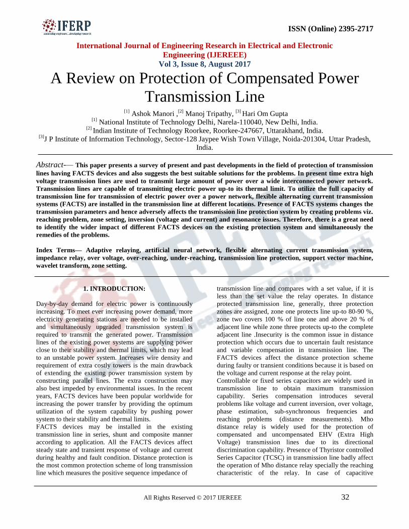
faults[19]–[21]. An elementary single phase thyristor
controlled series capacitor (TCSC) is shown in fig. 1 (a).It
consists of a fixed capacitor (CS), shunted through a
reactor of inductance LS in series with a bidirectional
thyristor switch. Current in the reactor can be controlled
from maximum value to zero by the method of firing
angle delay control. Complete range of α for
Fig. 1. Complete firing angle range of single phase
TCSC.
ISSN (Online) 2395-2717
International Journal of Engineering Research in Electrical and Electronic
Engineering (IJEREEE)
Vol 3, Issue 8, August 2017
All Rights Reserved © 2017 IJEREEE 34
capacitive and inductive compensation is shown in figure
1(b). In normal operating condition, TCSC
operates in four different modes and depending on MOV
conduction it shows reaching problems:
(i) Capacitive Boost Mode (αClim< α <π / 2)
(ii) Inductive Boost Mode (0 < α < αLlim)
(iii) Blocking Mode (α=π/2)
(iv) Bypass Mode (α = 0)
2.1.1.1 Reaching Problems
In TCSC transmission line, reach measurement
by distance relay depends upon the status of the TCSC
impedance which is varying in nature. The varying nature
of impedance inserted by TCSC in the line creates under-
reaching and over-reaching at the relay point in inductive
and capacitive compensation respectively and that is a
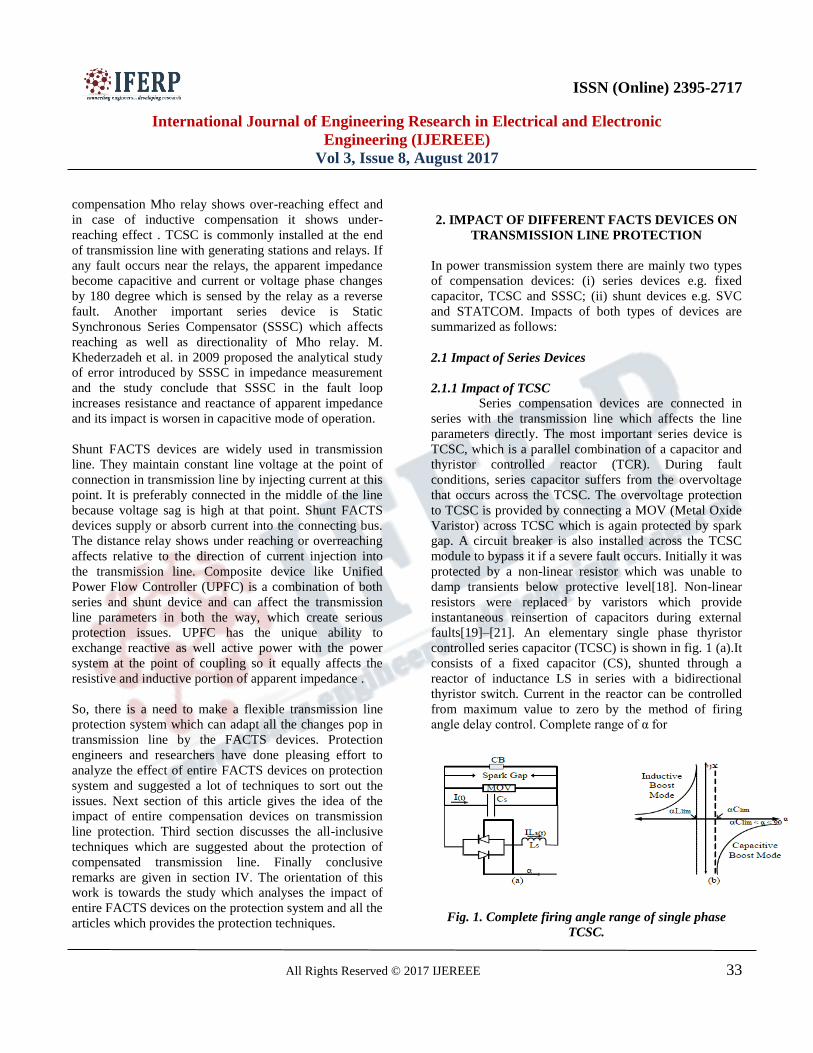
challenge to the protection engineer. Due to this variable
impedance, there is no clear boundary between zone 1 and
zone 2 hence overlapping area exists at the boundary as
shown in fig. 2. Due to this overlapping area, fault in zone
1 can extend up to zone 2 while zone 2 faults may fall
within zone 1 according to the mode of operation of
TCSC. This creates severe problem of zone identification
in case of fault in transmission line having TCSC.
Fig. 2. Overlapping area between zone one and zone
two.
2.1.1.2 Inversion Problems
(i) Voltage Inversion
In distance protection voltage inversion is a change of 180
degrees in the voltage phase angle at relay bus from the
actual fault voltage. For elements responding to phase
quantities, voltage inversion can occur for a fault near a
series capacitor if the impedance from the relay to the
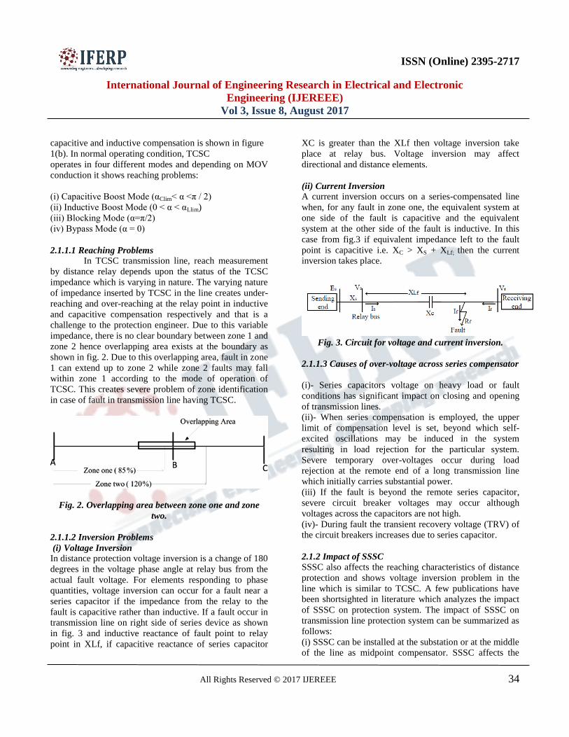
fault is capacitive rather than inductive. If a fault occur in
transmission line on right side of series device as shown
in fig. 3 and inductive reactance of fault point to relay
point in XLf, if capacitive reactance of series capacitor
XC is greater than the XLf then voltage inversion take
place at relay bus. Voltage inversion may affect
directional and distance elements.
(ii) Current Inversion
A current inversion occurs on a series-compensated line
when, for any fault in zone one, the equivalent system at
one side of the fault is capacitive and the equivalent
system at the other side of the fault is inductive. In this
case from fig.3 if equivalent impedance left to the fault
point is capacitive i.e. XC > XS + XLf; then the current
inversion takes place.
Fig. 3. Circuit for voltage and current inversion.
2.1.1.3 Causes of over-voltage across series compensator
(i)- Series capacitors voltage on heavy load or fault
conditions has significant impact on closing and opening
of transmission lines.
(ii)- When series compensation is employed, the upper
limit of compensation level is set, beyond which self-
excited oscillations may be induced in the system
resulting in load rejection for the particular system.
Severe temporary over-voltages occur during load
rejection at the remote end of a long transmission line
which initially carries substantial power.
(iii) If the fault is beyond the remote series capacitor,
severe circuit breaker voltages may occur although
voltages across the capacitors are not high.
(iv)- During fault the transient recovery voltage (TRV) of
the circuit breakers increases due to series capacitor.
2.1.2 Impact of SSSC
SSSC also affects the reaching characteristics of distance
protection and shows voltage inversion problem in the
line which is similar to TCSC. A few publications have
been shortsighted in literature which analyzes the impact
of SSSC on protection system. The impact of SSSC on
transmission line protection system can be summarized as
follows:
(i) SSSC can be installed at the substation or at the middle
of the line as midpoint compensator. SSSC affects the
ISSN (Online) 2395-2717
International Journal of Engineering Research in Electrical and Electronic
Engineering (IJEREEE)
Vol 3, Issue 8, August 2017
All Rights Reserved © 2017 IJEREEE 35
protection system depending upon its location. SSSC does
not affect the line protection system if not present in the
fault loop.
(ii) SSSC is connected in series with the transmission line
and works in capacitive and inductive mode of operation
so it shows both over-reaching and under-reaching effects
at relay end.
(iii) SSSC share both the active and reactive power in
transmission line so it affects resistance as well as
reactance of apparent impedance in transmission line.
(iv) Capacitive mode of SSSC mainly affects the apparent
resistance while inductive mode largely affects the
apparent reactance of transmission line.
(v) A. Kazemi et al. in 2008 presents the impact of
voltage transformer (VT) location w.r.t. SSSC and it is
concluded that for least impact of SSSC on distance
protection, VT in front of SSSC is the preferred location.
(vi) A. Kazemi et al. in 2009 gives the comparison of the
impact of SSSC and STATCOM on distance trip
characteristics and showed that for line end installation,
the impact of SSSC is more while for mid-point
installation STATCOM impact is more.
2.2 Impact of shunt devices
Presence of shunt FACTS device significantly
affects the performance of protection system and may
create security and reliability issues. It maintains constant
line voltage at the point of connection in transmission line
by injecting current at that point. It is preferably
connected in the middle of the line because voltage sag is
high at that point. Shunt FACTS devices supply or absorb
current into the connecting bus. The distance relay shows
under reaching or overreaching effects relative to the
direction of current injection into the transmission line. It
was found that mid-point FACTS compensation could
affect the distance relays concerning impedance
measurement, phase selection and operating times leading
to under-reaching and over-reaching of Mho relay.
2.2.1 Reaching Problems
Basic principle of distance protection is to
measure impedance between relay point and the fault
point; if it is less than the set value then the relay trips. In
the normal loading conditions with STATCOM,
resistance values are more and reactance values are less
when compared to the resistance and reactance values
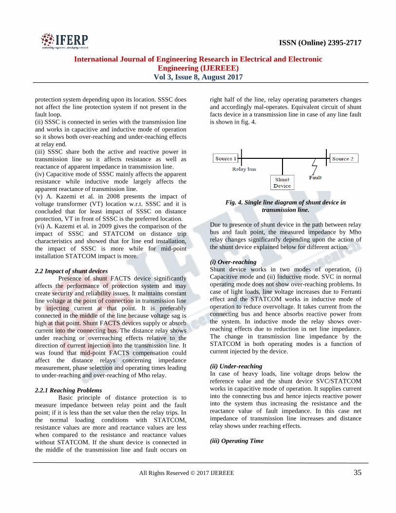
without STATCOM. If the shunt device is connected in
the middle of the transmission line and fault occurs on
right half of the line, relay operating parameters changes
and accordingly mal-operates. Equivalent circuit of shunt
facts device in a transmission line in case of any line fault
is shown in fig. 4.
Fig. 4. Single line diagram of shunt device in
transmission line.
Due to presence of shunt device in the path between relay
bus and fault point, the measured impedance by Mho
relay changes significantly depending upon the action of
the shunt device explained below for different action.
(i) Over-reaching
Shunt device works in two modes of operation, (i)
Capacitive mode and (ii) Inductive mode. SVC in normal
operating mode does not show over-reaching problems. In
case of light loads, line voltage increases due to Ferranti
effect and the STATCOM works in inductive mode of
operation to reduce overvoltage. It takes current from the
connecting bus and hence absorbs reactive power from
the system. In inductive mode the relay shows over-
reaching effects due to reduction in net line impedance.
The change in transmission line impedance by the
STATCOM in both operating modes is a function of
current injected by the device.
(ii) Under-reaching
In case of heavy loads, line voltage drops below the
reference value and the shunt device SVC/STATCOM
works in capacitive mode of operation. It supplies current
into the connecting bus and hence injects reactive power
into the system thus increasing the resistance and the
reactance value of fault impedance. In this case net
impedance of transmission line increases and distance
relay shows under reaching effects.
(iii) Operating Time
ISSN (Online) 2395-2717
International Journal of Engineering Research in Electrical and Electronic
Engineering (IJEREEE)
Vol 3, Issue 8, August 2017
All Rights Reserved © 2017 IJEREEE 36
Mho relay responds within the time after the fault occurs
until steady state value of the line impedance is found and
for Mho relay usually the operating time is less than 1
cycle. In case of fault, shunt device takes 5 to 7 cycles to
settle down in steady state condition. So the operating
time of Mho relay increases significantly high.
(iv) Phase selection
In case of mid-point shunt compensation if any
unsymmetrical fault occurs in the transmission line, the
faulty phase experiences severe under voltage effect as
compared to healthy phase. Shunt FACTS device supplies
even equal compensation for all the phases and healthy
phase voltage increases due to this overcompensation.
Due to this overcompensation healthy phase may
experience high line current and the overcurrent relay
may result it as a fault.
2.3 Impact of Composite device: UPFC
UPFC is the combination of SSSC (a series device) and
STATCOM (a shunt device), so it affects the protection
system in more complex manner. UPFC can consume
both active power and reactive power. UPFC has more
influence on apparent resistance because of the active
power consumed by SSSC and STATCOM. The effect of
UPFC on apparent impedance measurement can be
summarized as follows:
(i) UPFC has greater influence on the apparent resistance;
this is due to the active power injection and consumption
by both SSSC and STATCOM.
(ii) When SSSC consumes active power, the apparent
resistance will increase and when SSSC inject active
power, the apparent resistance will decrease.
(iii) When the SSSC injects reactive power into the
system, it is operated like a series capacitor and the
apparent impedance decreases, in this case Mho relay
overreaches. When it consumes reactive power from the
system, it is operated like a series inductance and the
apparent impedance increases and Mho relay overreaches.
(iv) Apparent fault impedance is influenced by the
reactive power injected/absorbed by the STATCOM,
which will result in the under reaching or over reaching of
distance relay respectively.
3. PROTECTION TECHNIQUES
3.1 Protection of Series Compensated Line
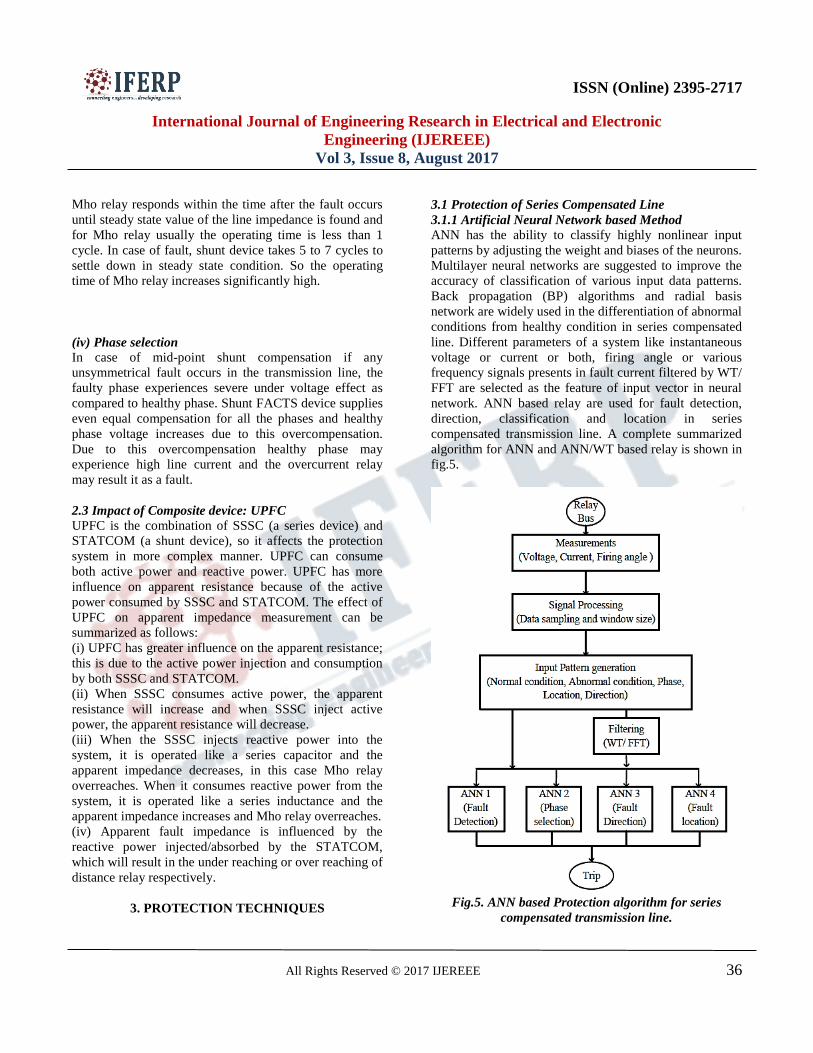
3.1.1 Artificial Neural Network based Method
ANN has the ability to classify highly nonlinear input
patterns by adjusting the weight and biases of the neurons.
Multilayer neural networks are suggested to improve the
accuracy of classification of various input data patterns.
Back propagation (BP) algorithms and radial basis
network are widely used in the differentiation of abnormal
conditions from healthy condition in series compensated
line. Different parameters of a system like instantaneous
voltage or current or both, firing angle or various
frequency signals presents in fault current filtered by WT/
FFT are selected as the feature of input vector in neural
network. ANN based relay are used for fault detection,
direction, classification and location in series
compensated transmission line. A complete summarized
algorithm for ANN and ANN/WT based relay is shown in
fig.5.
Fig.5. ANN based Protection algorithm for series
compensated transmission line.
ISSN (Online) 2395-2717
International Journal of Engineering Research in Electrical and Electronic
Engineering (IJEREEE)
Vol 3, Issue 8, August 2017
All Rights Reserved © 2017 IJEREEE 37
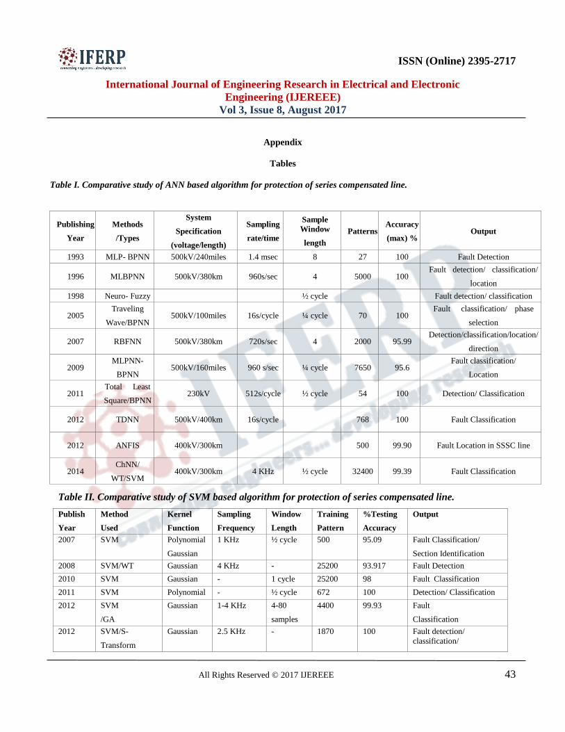
Table I (Given in Appendix) shows the year wise
development in neural network based
techniques for protection of series compensated
transmission line.
It is concluded that BPNN (Back-propagation neural
networks) is easy to implement and frequently used for
fault detection with classification accuracy achieved up to
100%. Although, it suffers from local conversion and
gives false results. RBFNN (Radial basis feed-forward
neural networks) are
generally faster and less number of parameters are
required to train. In most of the algorithms, rated system
voltage is chosen to be 400kV or 500kV. Whereas in
newly UHV transmission system has been installed above
1000kV in which transients are severe and needed to be
analyzed with respect to ANN. A versatile ANN structure
can be achieved through training it by a large number of
patterns and it can be observed that for less numbers of
testing samples can show dummy increase in percentage
accuracy.
3.1.2 Support Vector Machine Based Algorithms
The SVM is a machine learning technique used for
statistical classification and regression analysis. SVM
constructs a number of hyper planes in a high dimensional
space to separate data points which belongs to different
classes. ANN based relaying technique need lot of
training and testing before implementation, so it takes
more time on training and can suffer from multiple local
minima too. Due to better classification, features selection
capability and fast convergence rate of SVM, it is used as
a pattern classifier for obtaining healthy and faulty, phase
selection and fault location in series compensated line.
SVM are trained to detect, classify and zone identification
in compensated/uncompensated transmission line and
tested on various activation functions like polynomial,
Radial Gaussian, linear and sigmoidal to optimize the
classification. Optimization algorithm like Genetic
algorithm is also used to optimize the parameter of SVM
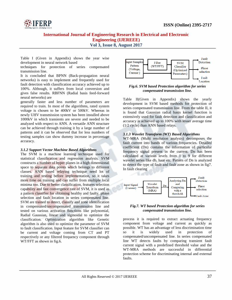
to fault classification. Input feature for SVM classifier can
be current and voltage coming from CT and PT
respectively or any filtered frequency component through
WT/FFT as shown in fig.6.
Fig.6. SVM based Protection algorithm for series
compensated transmission line.
Table II(Given in Appendix) shows the yearly
development in SVM based methods for protection of
series compensated transmission line. From the table II, it
is found that Gaussian radial basis kernel function is
extensively used for fault detection and classification and
accuracy is achieved up to 100% with lesser average time
(1/2 cycle) than ANN based relays.
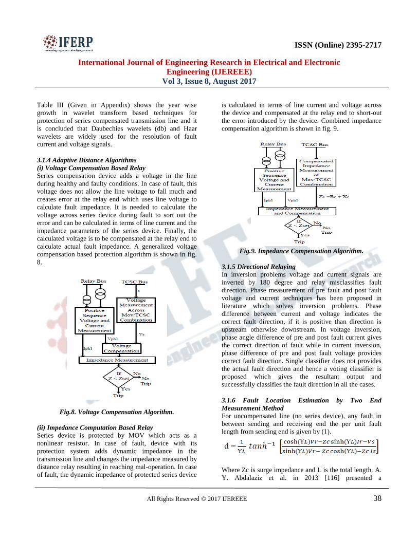
3.1.3 Wavelet Transform (WT) Based Algorithms
WT-MRA (Multi resolution analysis) decomposes the
fault current into bands of various frequencies. Detailed
coefficient (Dn) contains the information of particular
frequency signal present in the current. Dn has been
calculated at various levels from 1 to 9 for different
wavelet series like db, haar etc. Pattern of Dn is analyzed
to detect the type of fault and fault zone as shown in fig7.
In fault clearing
Fig.7. WT based Protection algorithm for series
compensated transmission line.
process it is required to extract actuating frequency
component from voltage and current as quickly as
possible. WT has an advantage of less discrimination time
so it is widely used in protection of
compensated/uncompensated line. In series compensated
line WT detects faults by comparing transient fault
current signal with a predefined threshold value and the
WT-MRA methods are successful in differential
protection scheme for discriminating internal and external
faults.
ISSN (Online) 2395-2717
International Journal of Engineering Research in Electrical and Electronic
Engineering (IJEREEE)
Vol 3, Issue 8, August 2017
All Rights Reserved © 2017 IJEREEE 38
Table III (Given in Appendix) shows the year wise
growth in wavelet transform based techniques for
protection of series compensated transmission line and it
is concluded that Daubechies wavelets (db) and Haar
wavelets are widely used for the resolution of fault
current and voltage signals.
3.1.4 Adaptive Distance Algorithms
(i) Voltage Compensation Based Relay
Series compensation device adds a voltage in the line
during healthy and faulty conditions. In case of fault, this
voltage does not allow the line voltage to fall much and
creates error at the relay end which uses line voltage to
calculate fault impedance. It is needed to calculate the
voltage across series device during fault to sort out the
error and can be calculated in terms of line current and the
impedance parameters of the series device. Finally, the
calculated voltage is to be compensated at the relay end to
calculate actual fault impedance. A generalized voltage
compensation based protection algorithm is shown in fig.
8.
Fig.8. Voltage Compensation Algorithm.
(ii) Impedance Computation Based Relay
Series device is protected by MOV which acts as a
nonlinear resistor. In case of fault, device with its
protection system adds dynamic impedance in the
transmission line and changes the impedance measured by
distance relay resulting in reaching mal-operation. In case
of fault, the dynamic impedance of protected series device
is calculated in terms of line current and voltage across
the device and compensated at the relay end to short-out
the error introduced by the device. Combined impedance
compensation algorithm is shown in fig. 9.
Fig.9. Impedance Compensation Algorithm.
3.1.5 Directional Relaying
In inversion problems voltage and current signals are
inverted by 180 degree and relay misclassifies fault
direction. Phase measurement of pre fault and post fault
voltage and current techniques has been proposed in
literature which solves inversion problems. Phase
difference between current and voltage indicates the
correct fault direction, if it is positive than direction is
upstream otherwise downstream. In voltage inversion,
phase angle difference of pre and post fault current gives
the correct direction of fault while in current inversion,
phase difference of pre and post fault voltage provides
correct fault direction. Single classifier does not provides
the actual fault direction and hence a voting classifier is
proposed which gives the resultant output and
successfully classifies the fault direction in all the cases.
3.1.6 Fault Location Estimation by Two End
Measurement Method
For uncompensated line (no series device), any fault in
between sending and receiving end the per unit fault
length from sending end is given by (1).
Where Zc is surge impedance and L is the total length. A.
Y. Abdalaziz et al. in 2013 [116] presented a
ISSN (Online) 2395-2717
International Journal of Engineering Research in Electrical and Electronic
Engineering (IJEREEE)
Vol 3, Issue 8, August 2017
All Rights Reserved © 2017 IJEREEE 39
synchronized measurement technique to find the exact
fault location in uncompensated and series compensated
transmission line. The proposed algorithm uses
distributed parameters of the transmission line and utilizes
the synchronized measurements of voltages and currents
at both ends of the line as shown in fig. 10.
In case of series compensation, the transmission line is
divided into two sections, section between „s‟ to „c1‟ and
section „c2‟ to „r‟. Voltage across series device Vc1 and
Vc2 is calculated by synchronizing measurement of
current through the device and fault location can be
calculated in two different sections from (1).
B. Vyas et al. [117] presented a comparative study of all
fault location techniques for series compensated line.
Parallel computation based adaptive neuro-fuzzy
inference system (ANFIS) for fault location in
transmission line having SSSC has been suggested by E
Mohagheghi et al. in 2012 [84], in this scheme, apparent
impedance is calculated for various faults created at
several locations and simultaneously SSSC equivalent
impedance is calculated to train the neuro-fuzzy system to
find out the optimized fault location.
3.1.7 Overvoltage Protection of Series Compensators
Based upon the experimental studies following actions
have been suggested to protect series compensator from
overvoltage (TRV).
(i) Installation of fast protective device across the series
device for bypassing.
(ii) Force triggering of protective gap or by lowering the
breakdown voltage of gap.
(iii) Impedance has to be inserting in series or an arrester
in parallel with the circuit breaker to reduce the peak of
TRV.
(iv) Maximum compensation has to be set up-to
permissible limit. Lower value of compensation generates
lower overvoltage.
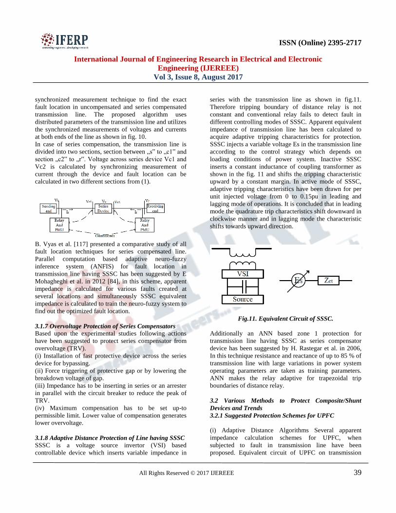
3.1.8 Adaptive Distance Protection of Line having SSSC
SSSC is a voltage source invertor (VSI) based
controllable device which inserts variable impedance in
series with the transmission line as shown in fig.11.
Therefore tripping boundary of distance relay is not
constant and conventional relay fails to detect fault in
different controlling modes of SSSC. Apparent equivalent
impedance of transmission line has been calculated to
acquire adaptive tripping characteristics for protection.
SSSC injects a variable voltage Es in the transmission line
according to the control strategy which depends on
loading conditions of power system. Inactive SSSC
inserts a constant inductance of coupling transformer as
shown in the fig. 11 and shifts the tripping characteristic
upward by a constant margin. In active mode of SSSC,
adaptive tripping characteristics have been drawn for per
unit injected voltage from 0 to 0.15pu in leading and
lagging mode of operations. It is concluded that in leading
mode the quadrature trip characteristics shift downward in
clockwise manner and in lagging mode the characteristic
shifts towards upward direction.
Fig.11. Equivalent Circuit of SSSC.
Additionally an ANN based zone 1 protection for
transmission line having SSSC as series compensator
device has been suggested by H. Rastegar et al. in 2006,
In this technique resistance and reactance of up to 85 % of
transmission line with large variations in power system
operating parameters are taken as training parameters.
ANN makes the relay adaptive for trapezoidal trip
boundaries of distance relay.
3.2 Various Methods to Protect Composite/Shunt
Devices and Trends
3.2.1 Suggested Protection Schemes for UPFC
(i) Adaptive Distance Algorithms Several apparent
impedance calculation schemes for UPFC, when
subjected to fault in transmission line have been
proposed. Equivalent circuit of UPFC on transmission
ISSN (Online) 2395-2717
International Journal of Engineering Research in Electrical and Electronic
Engineering (IJEREEE)
Vol 3, Issue 8, August 2017
All Rights Reserved © 2017 IJEREEE 40
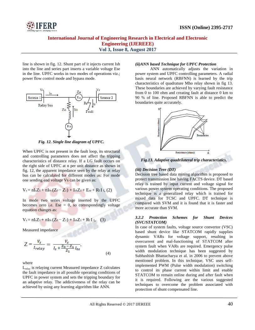
line is shown in fig. 12. Shunt part of it injects current Ish
into the line and series part inserts a variable voltage Ese
in the line. UPFC works in two modes of operations viz.;
power flow control mode and bypass mode.
Fig. 12. Single line diagram of UPFC.
When UPFC is not present in the fault loop, its structural
and controlling parameters does not affect the tripping
characteristics of distance relay. If a LG fault occurs on
the right side of UPFC at n per unit distance as shown in
fig. 12, the apparent impedance seen by the relay at relay
bus can be calculated for different modes as: For mode
one sending end voltage Vs can be given as:
Vs = nIsZ1 + nI0s (Z0 − Z1) + IshZ1 + Ese + Rf I f, (2)
In mode two series voltage inserted by the UPFC
becomes zero i.e. Ese = 0, so correspondingly voltage
equation changes as:
Vs = nIsZ1 + nI0s (Z0 − Z1) + IshZ1 + Rf I f, (3)
Measured impedance
(4)
where
Lrelay is relaying current Measured impedance Z calculates
the fault impedance in all possible operating conditions of
UPFC in power system and sets the tripping boundary for
an adaptive relay. The addictiveness of the relay can be
achieved by using any learning algorithm like ANN.
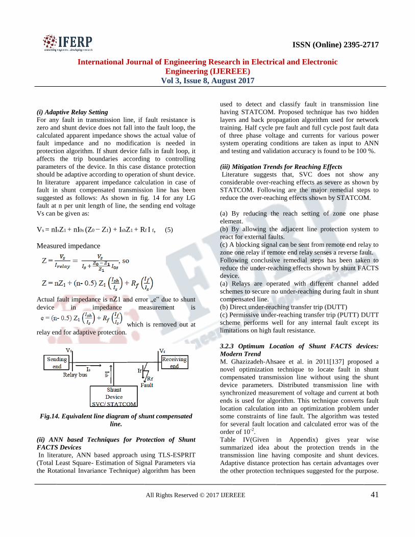
(ii)ANN based Technique for UPFC Protection
ANN automatically adjusts the variation in
power system and UPFC controlling parameters. A radial
basis neural network (RBFNN) is learned by the trip
characteristics of quadrature Mho relay shown in fig 13.
These boundaries are achieved by varying fault resistance
from 0 to 100 ohm and creating fault at distance 0 km to
90 % of line. Proposed RBFNN is able to predict the
boundaries quite accurately.
Fig.13. Adaptive quadrilateral trip characteristics.
(iii) Decision Tree (DT)
Decision tree based data mining algorithm is proposed to
protect transmission line having FACTS device. DT based
relay is trained by input current and voltage signal for
various power system operating conditions. The proposed
technique is a generalized relay which is trained for
mixed data for TCSC and UPFC. DT technique is
compared with SVM and it is found that it is faster and
more accurate than SVM.
3.2.2 Protection Schemes for Shunt Devices
(SVC/STATCOM)
In case of system faults, voltage source convertor (VSC)
based shunt device like STATCOM rapidly supplies
dynamic VARs for voltage support, resulting in
overcurrent and mal-functioning of STATCOM after
system fault when VARs are required. Emergency pulse
width modulation technique has been suggested by
Subhashish Bhattacharya et al. in 2006 to prevent above
mentioned problem. In this technique, VSC uses self-
implemented PWM (Pulse width modulation) switching
to control its phase current within limit and enable
STATCOM to remain online during and after fault when
it is required. Following are the various suggested
techniques to overcome the problem associated with
protection of shunt compensated line.
ISSN (Online) 2395-2717
International Journal of Engineering Research in Electrical and Electronic
Engineering (IJEREEE)
Vol 3, Issue 8, August 2017
All Rights Reserved © 2017 IJEREEE 41
(i) Adaptive Relay Setting
For any fault in transmission line, if fault resistance is
zero and shunt device does not fall into the fault loop, the
calculated apparent impedance shows the actual value of
fault impedance and no modification is needed in
protection algorithm. If shunt device falls in fault loop, it
affects the trip boundaries according to controlling
parameters of the device. In this case distance protection
should be adaptive according to operation of shunt device.
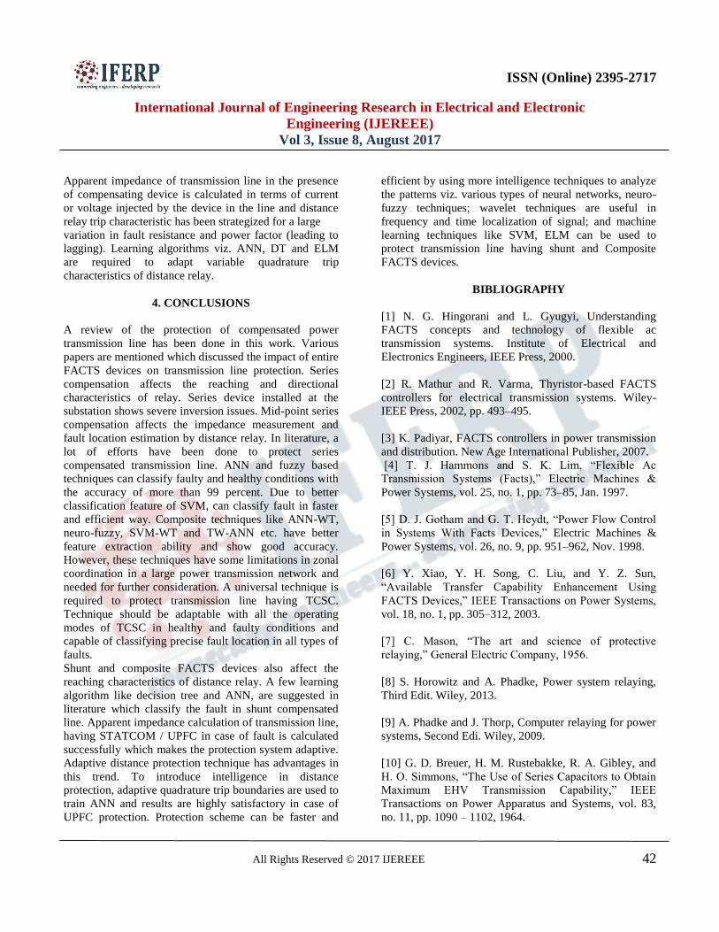
In literature apparent impedance calculation in case of
fault in shunt compensated transmission line has been
suggested as follows: As shown in fig. 14 for any LG
fault at n per unit length of line, the sending end voltage
Vs can be given as:
Vs = nIsZ1 + nI0s (Z0 − Z1) + IshZ1 + Rf I f, (5)
Measured impedance
Actual fault impedance is nZ1 and error „e‟ due to shunt
device in impedance measurement is
which is removed out at
relay end for adaptive protection.
Fig.14. Equivalent line diagram of shunt compensated
line.
(ii) ANN based Techniques for Protection of Shunt
FACTS Devices
In literature, ANN based approach using TLS-ESPRIT
(Total Least Square- Estimation of Signal Parameters via
the Rotational Invariance Technique) algorithm has been
used to detect and classify fault in transmission line
having STATCOM. Proposed technique has two hidden
layers and back propagation algorithm used for network
training. Half cycle pre fault and full cycle post fault data
of three phase voltage and currents for various power
system operating conditions are taken as input to ANN
and testing and validation accuracy is found to be 100 %.
(iii) Mitigation Trends for Reaching Effects
Literature suggests that, SVC does not show any
considerable over-reaching effects as severe as shown by
STATCOM. Following are the major remedial steps to
reduce the over-reaching effects shown by STATCOM.
(a) By reducing the reach setting of zone one phase
element.
(b) By allowing the adjacent line protection system to
react for external faults.
(c) A blocking signal can be sent from remote end relay to
zone one relay if remote end relay senses a reverse fault.
Following conclusive remedial steps has been taken to
reduce the under-reaching effects shown by shunt FACTS
device.
(a) Relays are operated with different channel added
schemes to secure no under-reaching during fault in shunt
compensated line.
(b) Direct under-reaching transfer trip (DUTT)
(c) Permissive under-reaching transfer trip (PUTT) DUTT
scheme performs well for any internal fault except its
limitations on high fault resistance.
3.2.3 Optimum Location of Shunt FACTS devices:
Modern Trend
M. Ghazizadeh-Ahsaee et al. in 2011[137] proposed a
novel optimization technique to locate fault in shunt
compensated transmission line without using the shunt
device parameters. Distributed transmission line with
synchronized measurement of voltage and current at both
ends is used for algorithm. This technique converts fault
location calculation into an optimization problem under
some constraints of line fault. The algorithm was tested
for several fault location and calculated error was of the
order of 10-2
.
Table IV(Given in Appendix) gives year wise
summarized idea about the protection trends in the
transmission line having composite and shunt devices.
Adaptive distance protection has certain advantages over
the other protection techniques suggested for the purpose.
ISSN (Online) 2395-2717
International Journal of Engineering Research in Electrical and Electronic
Engineering (IJEREEE)
Vol 3, Issue 8, August 2017
All Rights Reserved © 2017 IJEREEE 42
Apparent impedance of transmission line in the presence
of compensating device is calculated in terms of current
or voltage injected by the device in the line and distance
relay trip characteristic has been strategized for a large
variation in fault resistance and power factor (leading to
lagging). Learning algorithms viz. ANN, DT and ELM
are required to adapt variable quadrature trip
characteristics of distance relay.
4. CONCLUSIONS
A review of the protection of compensated power
transmission line has been done in this work. Various
papers are mentioned which discussed the impact of entire
FACTS devices on transmission line protection. Series
compensation affects the reaching and directional
characteristics of relay. Series device installed at the
substation shows severe inversion issues. Mid-point series
compensation affects the impedance measurement and
fault location estimation by distance relay. In literature, a
lot of efforts have been done to protect series
compensated transmission line. ANN and fuzzy based
techniques can classify faulty and healthy conditions with
the accuracy of more than 99 percent. Due to better
classification feature of SVM, can classify fault in faster
and efficient way. Composite techniques like ANN-WT,
neuro-fuzzy, SVM-WT and TW-ANN etc. have better
feature extraction ability and show good accuracy.
However, these techniques have some limitations in zonal
coordination in a large power transmission network and
needed for further consideration. A universal technique is
required to protect transmission line having TCSC.
Technique should be adaptable with all the operating
modes of TCSC in healthy and faulty conditions and
capable of classifying precise fault location in all types of
faults.
Shunt and composite FACTS devices also affect the
reaching characteristics of distance relay. A few learning
algorithm like decision tree and ANN, are suggested in
literature which classify the fault in shunt compensated
line. Apparent impedance calculation of transmission line,
having STATCOM / UPFC in case of fault is calculated
successfully which makes the protection system adaptive.
Adaptive distance protection technique has advantages in
this trend. To introduce intelligence in distance
protection, adaptive quadrature trip boundaries are used to
train ANN and results are highly satisfactory in case of
UPFC protection. Protection scheme can be faster and
efficient by using more intelligence techniques to analyze
the patterns viz. various types of neural networks, neuro-
fuzzy techniques; wavelet techniques are useful in
frequency and time localization of signal; and machine
learning techniques like SVM, ELM can be used to
protect transmission line having shunt and Composite
FACTS devices.
BIBLIOGRAPHY
[1] N. G. Hingorani and L. Gyugyi, Understanding
FACTS concepts and technology of flexible ac
transmission systems. Institute of Electrical and
Electronics Engineers, IEEE Press, 2000.
[2] R. Mathur and R. Varma, Thyristor-based FACTS
controllers for electrical transmission systems. Wiley-
IEEE Press, 2002, pp. 493–495.
[3] K. Padiyar, FACTS controllers in power transmission
and distribution. New Age International Publisher, 2007.
[4] T. J. Hammons and S. K. Lim, “Flexible Ac
Transmission Systems (Facts),” Electric Machines &
Power Systems, vol. 25, no. 1, pp. 73–85, Jan. 1997.
[5] D. J. Gotham and G. T. Heydt, “Power Flow Control
in Systems With Facts Devices,” Electric Machines &
Power Systems, vol. 26, no. 9, pp. 951–962, Nov. 1998.
[6] Y. Xiao, Y. H. Song, C. Liu, and Y. Z. Sun,
“Available Transfer Capability Enhancement Using
FACTS Devices,” IEEE Transactions on Power Systems,
vol. 18, no. 1, pp. 305–312, 2003.
[7] C. Mason, “The art and science of protective
relaying,” General Electric Company, 1956.
[8] S. Horowitz and A. Phadke, Power system relaying,
Third Edit. Wiley, 2013.
[9] A. Phadke and J. Thorp, Computer relaying for power
systems, Second Edi. Wiley, 2009.
[10] G. D. Breuer, H. M. Rustebakke, R. A. Gibley, and
H. O. Simmons, “The Use of Series Capacitors to Obtain
Maximum EHV Transmission Capability,” IEEE
Transactions on Power Apparatus and Systems, vol. 83,
no. 11, pp. 1090 – 1102, 1964.
ISSN (Online) 2395-2717
International Journal of Engineering Research in Electrical and Electronic
Engineering (IJEREEE)
Vol 3, Issue 8, August 2017
All Rights Reserved © 2017 IJEREEE 43
Appendix
Tables
Table I. Comparative study of ANN based algorithm for protection of series compensated line.
Publishing
Year
Methods
/Types
System
Specification
(voltage/length)
Sampling
rate/time
Sample
Window
length
Patterns Accuracy
(max) % Output
1993 MLP- BPNN 500kV/240miles 1.4 msec 8 27 100 Fault Detection
1996 MLBPNN 500kV/380km 960s/sec 4 5000 100 Fault detection/ classification/
location
1998 Neuro- Fuzzy ½ cycle Fault detection/ classification
2005 Traveling
Wave/BPNN 500kV/100miles 16s/cycle ¼ cycle 70 100
Fault classification/ phase
selection
2007 RBFNN 500kV/380km 720s/sec 4 2000 95.99 Detection/classification/location/
direction
2009 MLPNN-
BPNN 500kV/160miles 960 s/sec ¼ cycle 7650 95.6
Fault classification/
Location
2011 Total Least
Square/BPNN 230kV 512s/cycle ½ cycle 54 100 Detection/ Classification
2012 TDNN 500kV/400km 16s/cycle 768 100 Fault Classification
2012 ANFIS 400kV/300km 500 99.90 Fault Location in SSSC line
2014 ChNN/
WT/SVM 400kV/300km 4 KHz ½ cycle 32400 99.39 Fault Classification
Table II. Comparative study of SVM based algorithm for protection of series compensated line.
Publish
Year
Method
Used
Kernel
Function
Sampling
Frequency
Window
Length
Training
Pattern
%Testing
Accuracy
Output
2007 SVM Polynomial
Gaussian
1 KHz ½ cycle 500 95.09 Fault Classification/
Section Identification
2008 SVM/WT Gaussian 4 KHz - 25200 93.917 Fault Detection
2010 SVM Gaussian - 1 cycle 25200 98 Fault Classification
2011 SVM Polynomial - ½ cycle 672 100 Detection/ Classification
2012 SVM
/GA
Gaussian 1-4 KHz 4-80
samples
4400 99.93 Fault
Classification
2012 SVM/S-
Transform
Gaussian 2.5 KHz - 1870 100 Fault detection/
classification/
Location
ISSN (Online) 2395-2717
International Journal of Engineering Research in Electrical and Electronic
Engineering (IJEREEE)
Vol 3, Issue 8, August 2017
All Rights Reserved © 2017 IJEREEE 44
2012 SVM/WT Gaussian 4 KHz ½ cycle 2400 99.81 Fault Detection
2014 SVM/ANN Gaussian 4 kHz ½ cycle 32400 99.39 Fault classification
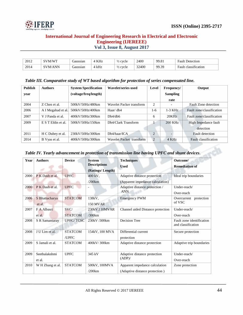
Table III. Comparative study of WT based algorithm for protection of series compensated line.
Publish
year
Authors System Specification
(voltage/freq/length)
Wavelet/series used Level Frequency/
Sampling
rate
Output
2004 Z Chen et al. 500kV/50Hz/480km Wavelet Packer transform 2 - Fault Zone detection
2006 A I Megahad et al. 500kV/50Hz/400km Haar/ db4 1-6 1-3 KHz Fault zone/classification
2007 V J Panda et al. 400kV/50Hz/300km Db4/db6 6 20KHz Fault zone/classification
2009 E S T Eldin et al. 500kV/50Hz/150km Db4/Clark Transform 1 200 KHz High Impedance fault
detection
2011 H C Dubey et al. 230kV/50Hz/300km Db4/haar/ICA 2 - Fault detection
2014 B Vyas et al. 400kV/50Hz/300km Wavelet Packet transform 2 4 KHz Fault classification
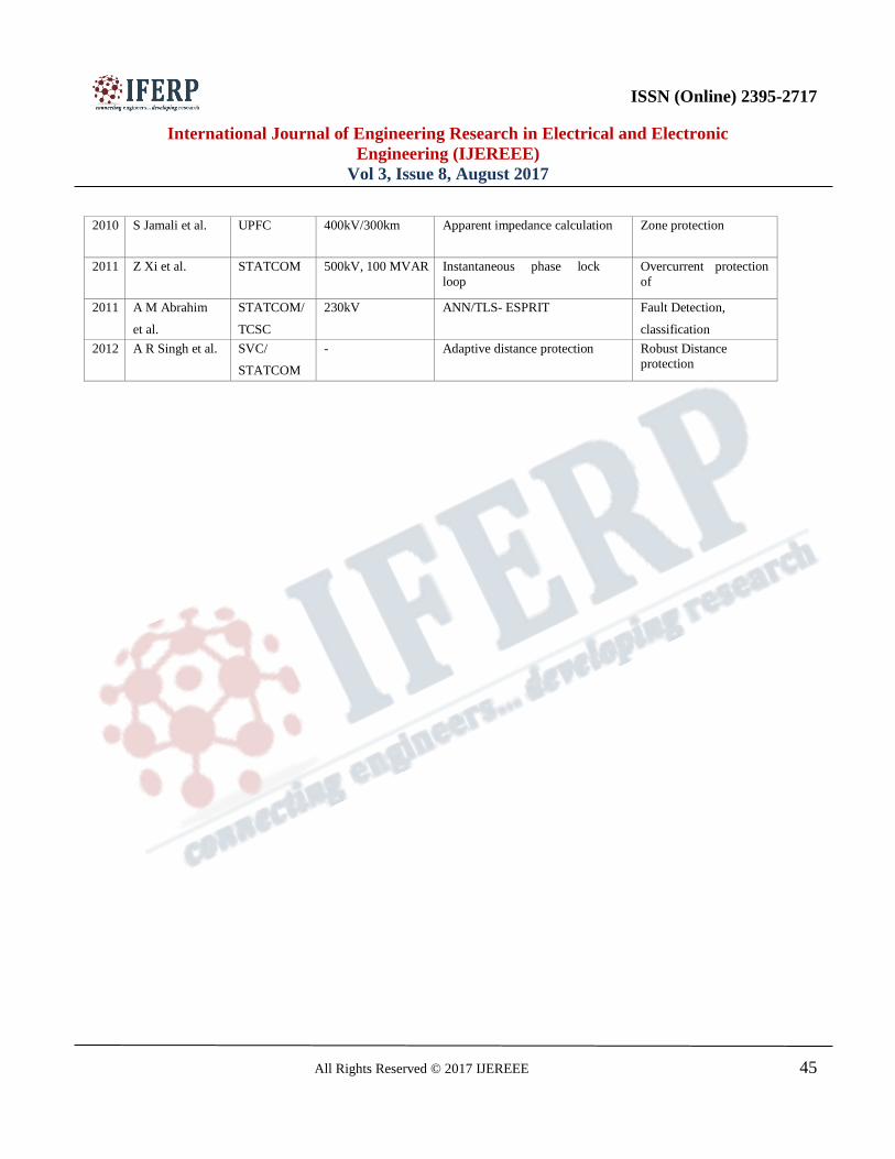
Table IV. Yearly advancement in protection of transmission line having UPFC and shunt devices.
Year Authors Device System
Descriptions
(Ratings/ Length)
Techniques
Used
Outcome/
Remediation of
2000 P K Dash et al. UPFC 400 kV,
/200km
Adaptive distance protection
(Apparent impedance calculation)
Ideal trip boundaries
2000 P K Dash et al. UPFC - Adaptive distance protection /
ANN
Under-reach/
Over-reach
2006 S Bhattacharya
et al.
STATCOM 138kV,
150 MVAR
Emergency PWM Overcurrent protection
of VSC
2007 F A Albasri
et al.
SVC/
STATCOM
230kV,110MVAR
/300km
Channel aided Distance protection Under-reach/
Over-reach
2008 S R Samantaray UPFC/ TCSC 230kV /300km Decision Tree Fault zone identification
and classification
2008 J U Lim et al. STATCOM
/UPFC
154kV, 100 MVA Differential current
protection
Secure protection
2009 S Jamali et al. STATCOM 400kV/ 300km Adaptive distance protection Adaptive trip boundaries
2009 Seethalakshmi
et al.
UPFC 345 kV Adaptive distance protection
(ADP)/
GRNN
Under-reach/
Over-reach
2010 W H Zhang et al. STATCOM 500kV, 100MVA
/200km
Apparent impedance calculation
(Adaptive distance protection )
Zone protection
ISSN (Online) 2395-2717
International Journal of Engineering Research in Electrical and Electronic
Engineering (IJEREEE)
Vol 3, Issue 8, August 2017
All Rights Reserved © 2017 IJEREEE 45
2010 S Jamali et al. UPFC 400kV/300km Apparent impedance calculation Zone protection
2011 Z Xi et al. STATCOM 500kV, 100 MVAR Instantaneous phase lock
loop
(IPLL)
Overcurrent protection
of
VSC 2011 A M Abrahim
et al.
STATCOM/
TCSC
230kV ANN/TLS- ESPRIT Fault Detection,
classification
2012 A R Singh et al. SVC/
STATCOM
- Adaptive distance protection Robust Distance
protection