Embed Size (px)
Citation preview
International Journal of Scientific & Engineering Research, Volume 7, Issue 5, May-2016 85 ISSN 2229-5518
IJSER © 2016 http://www.ijser.org
A Review on Microstructure of Friction Stir Welded Joint
Komal Rania, V.K. Patelb
aAssistant Professor at P.G.I. Roorkee
bAssistant Professor at G.B.P.E.C. Ghurdauri Pauri Garhwal
ABSTRACT
Friction stir welding is a solid state joining technique patented by The Welding Institute (TWI) in1991. New class of materials like metal matrix composites and difficult to weld materials can be easily weld by friction stir welding technique. A non-consumable tool made of harder material as compared to base material is used for joining operation. Semi-circular rings like milling process are formed on the upper surface of plates which makes contact with tool shoulder. Tool action greatly affects the microstructure of parent material. Frictional heating and stirring action of tool are responsible for total dynamic recrystallization in friction stir weld. Generally four zones are created by tool action in friction stir welding. Due to different microstructure all the four zones exhibit different properties. Selected parameters affect the microstructure of friction stir welding. This review represents the results of some researchers about microstructure before and after friction stir welding.
Keywords: Friction Stir Welding (FSW), Nugget Zone (NZ), Thermo-Mechanically Affected Zone (TMAZ), Heat Affected Zone (HAZ), Base Material (BM), Weld Zone (WZ).
1. INTRODUCTION
Friction stir welding is a solid-state joining
method patented in 1991 at The Welding
Institute (TWI) UK [1]. It can produce high
quality welds in materials like aluminium,
nickel, magnesium, titanium and steel which are
widely used in industries like automobiles,
aerospace and shipbuilding [2]. FSW is a
technique has proved suitable for joining the
materials which are generally considered as un-
weld able or difficult to weld [3]. FSW is an
effective method for joining particulate
reinforced metal matrix composite. Joints
produced by FSW eliminate defects like gas
occlusion, undesired interfacial reaction between
molten alloy and reinforcing particles,
inhomogeneous particles distribution after
welding which are induced by any other fusion
IJSER
International Journal of Scientific & Engineering Research, Volume 7, Issue 5, May-2016 86 ISSN 2229-5518
IJSER © 2016 http://www.ijser.org
welding technique like arc welding, TIG and
MIG etc. [4].
2. FRICTION STIR WELDING
2.1 Working Principle of FSW
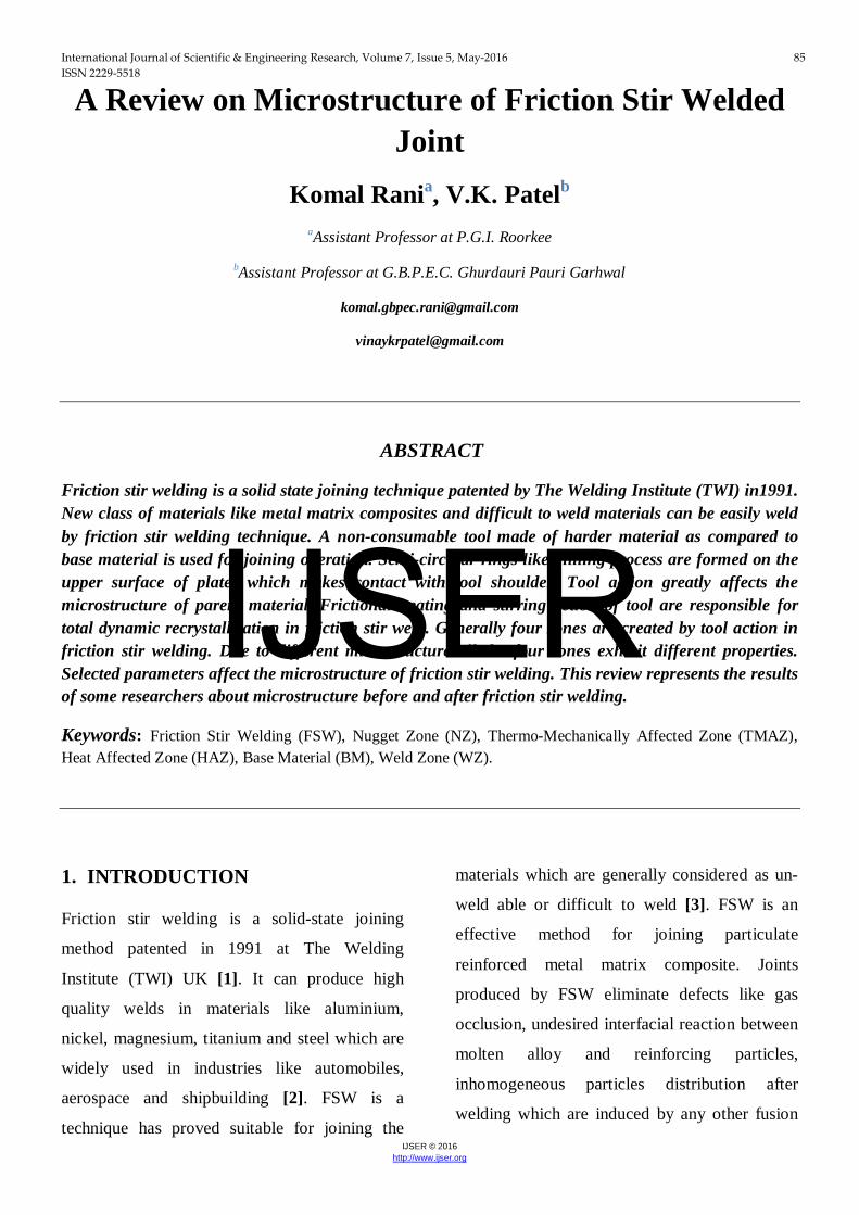
Friction stir welding follows the simple principle
of heat generation through friction as its name
implies. Name of FSW gives a clear description
of its working principle. It contains three words
in order friction + stir + welding. Firstly
frictional heat produced between tool and work-
piece surface soften the work piece material.
Secondly this soft material is stirred by rotating
tool from forward to backward direction. At last
weld is formed between the plates by cooling of
stirred material. Two separate plates which we
want to join clamp together on baking plates
with a zero root gap. FSW tool which is a
combination of shoulder and pin is inserted
between these plates. FSW tool rotates between
these two plates and traverse along weld
direction. Friction produced during rubbing of
tool with plate’s surfaces converts into heat. This
frictional heat forms weld between plates [5].
FIGURE 2.1: Schematic of Friction Stir Welding [6]
2.2 Heat Sources
There are two sources which are responsible for
production of heat in whole process.
i. Frictional heat produced between the tool
shoulder and work-piece material
surfaces.
ii. Heat produced by the mechanical mixing
process (forging and extrusion of
plasticized deformed material) [7].
Frictional heat produced in first stage has
capability to raise the temperature below the
melting temperature of work-piece which we
want to be joined. Soften material gets plastically
deformed by stirring action of tool and produced
heat by mechanical mixing. This second stage
produced heat further helps the work-piece
material for softening.
2.3 FSW Zones
Heat production, plastic deformation, and
dynamic recrystallization are occurred during
FSW process. These are responsible to form
different zones of micro-structure and material
properties. Tool shoulder in contact with upper
IJSER
International Journal of Scientific & Engineering Research, Volume 7, Issue 5, May-2016 87 ISSN 2229-5518
IJSER © 2016 http://www.ijser.org
most surface of work-piece material creates an
inordinate amount of heat as comparison to
bottom surface. This difference in thermal heat
input and boundary condition are responsible for
creating a through thickness variation in
recrystallization and grain growth which leads to
distinct lower and upper nuggets. Welds at least
of 2 cm thick has shown the clear distinction
between the upper and lower nuggets. Outside of
weld nugget zone there is another material zone.
This zone is called thermo mechanically affected
zone (TMAZ). TMAZ is thermally affected and
mechanically deformed through stirring tool pin
during FSW. This zone is shown as zone C in
following Fig. 2.2. There is also a forth material
zone. Being too distance, this zone is not
affected by the stirring of FSW tool but still
subjected to heat as heat was conducted away
from the FSW joint during processing. This zone
is known as heat affected zone (HAZ) [8]. HAZ
is shown as D in Fig. 2.2
FIGURE 2.2: FSW Zones [8]
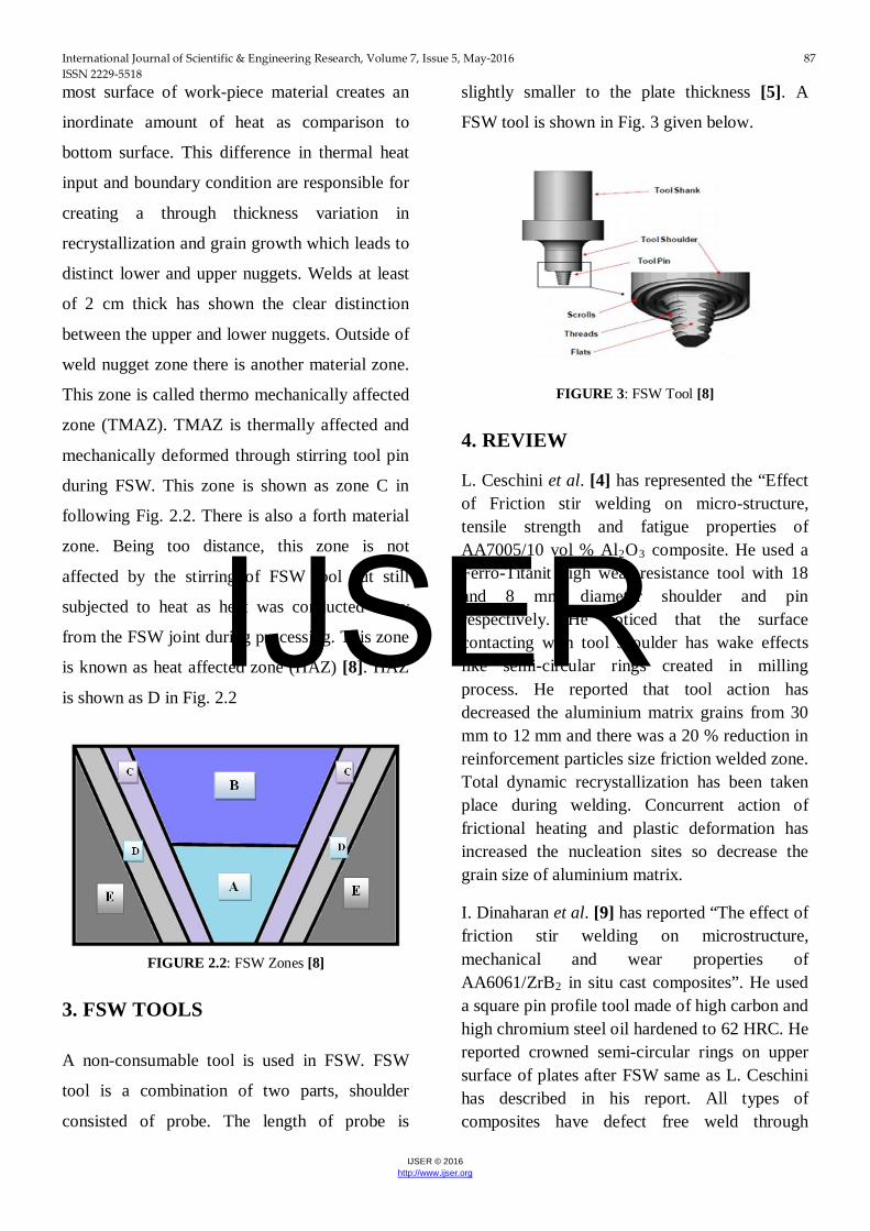
3. FSW TOOLS
A non-consumable tool is used in FSW. FSW
tool is a combination of two parts, shoulder
consisted of probe. The length of probe is
slightly smaller to the plate thickness [5]. A
FSW tool is shown in Fig. 3 given below.
FIGURE 3: FSW Tool [8]
4. REVIEW
L. Ceschini et al. [4] has represented the “Effect of Friction stir welding on micro-structure, tensile strength and fatigue properties of AA7005/10 vol % Al2O3 composite. He used a Ferro-Titanit high wear resistance tool with 18 and 8 mm diameter shoulder and pin respectively. He noticed that the surface contacting with tool shoulder has wake effects like semi-circular rings created in milling process. He reported that tool action has decreased the aluminium matrix grains from 30 mm to 12 mm and there was a 20 % reduction in reinforcement particles size friction welded zone. Total dynamic recrystallization has been taken place during welding. Concurrent action of frictional heating and plastic deformation has increased the nucleation sites so decrease the grain size of aluminium matrix.
I. Dinaharan et al. [9] has reported “The effect of friction stir welding on microstructure, mechanical and wear properties of AA6061/ZrB2 in situ cast composites”. He used a square pin profile tool made of high carbon and high chromium steel oil hardened to 62 HRC. He reported crowned semi-circular rings on upper surface of plates after FSW same as L. Ceschini has described in his report. All types of composites have defect free weld through
IJSER

International Journal of Scientific & Engineering Research, Volume 7, Issue 5, May-2016 88 ISSN 2229-5518
IJSER © 2016 http://www.ijser.org
friction stir welding. He reported that four types of zone (base material, heat affected zone, thermo-mechanically affected zone and weld or nugget zone) were clearly visible in all three types of composites welded by FSW, Fig. 4.1. Casted AA6061 alloy exhibited dendritic structure in base material. He noticed that the presence of Mg2Si was higher than its solubility limit in alloy. There was exposure of frictional heating to HAZ. So HAZ showed refined dendritic structure with dissolved Mg2Si secondary phase as compared to base material. On other hand TMAZ exhibited highly elongated grains of alloy with thoroughly recrystallized microstructure. He reported that heavy plastic deformation followed by dynamic recrystallization has altered the microstructure into equiaxed recrystallized grains. After FSW of composites reinforced with ZrB2 particles, microstructure exhibited the homogeneous dispersion of reinforcement with circular shape. There was no clear difference has been noticed between HAZ and BM. H reported that heat generated by friction and stresses have induced plastic deformation in TMAZ. TMAZ has exhibited stretched ZrB2 particles along shear stress directions. Rotation up-to 90o has been reported into matrix grains within TMAZ. He reported that ZrB2 particles have homogeneous dispersion in weld zone. Due to homogeneous dispersion there was an increment has been noticed in nucleation sites resulted reduction in matrix grain size. He also reported that tools stirring action was responsible for fragmented clusters of reinforcement within weld zone. There was a heavy reduction in particles cluster size up-to 2-3 µm has been noticed within weld zone.
FIGURE 4.1: Optical micrograph of friction stir welded
AA6061/5 wt% ZrB2 composite. (a) Parent material, (b)
Heat affected zone, (c) Thermo mechanically affected
zone, (d) weld zone. [9]
John A. Wert [10] has been studied the “Microstructure of friction stir weld joints between an aluminium base-metal matrix composite and a monolithic aluminium alloy”. He used a square pin profiled rounded corner tool. He revealed that matrix has a fine grained structure at the centre of weld with homogeneously dispersed Al2O3 particles. He reported that from the two materials if softer material is on the retreating side than its easy to transfer it to advancing side but if harder material on retreating side there is a less amount of material transferred to advancing side.
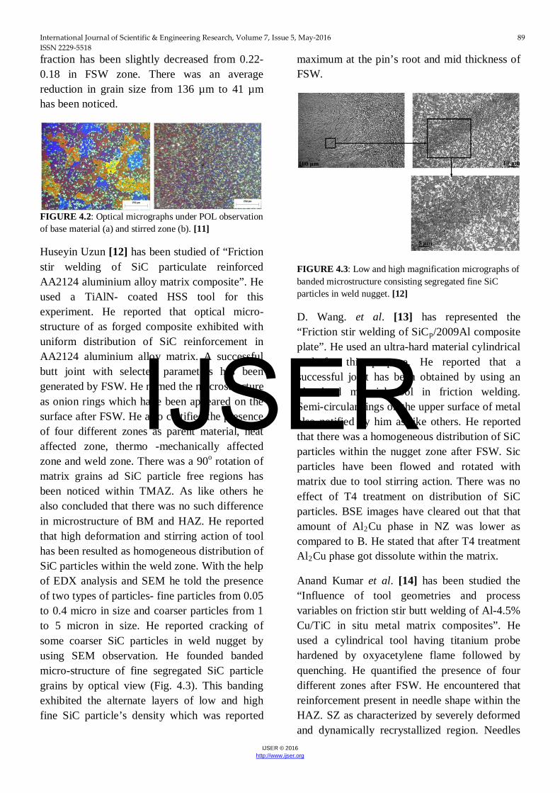
G. Minak et al. [11] has studied “Fatigue properties of friction stir welded particulate reinforced aluminium matrix composites”. He selected a highly wear resistant steel, heat treated to 64 HRC as tool material. He concluded that FSW was capable to generate the successful joint with all selected process parameters. He recounted the presence of four zones- BM, TMAZ, HAZ and Stirred Zone. He identified refinement in ceramic reinforcement particles and matrix grains size. There was an increment reported number of reinforcing particles within the stirred zone (Fig. 4.2). He reported that stress induced by tool decreased the particle area from 94 to 59 µm2 in lower zone near the pin end. He also stated that local reinforcement volume
IJSER
International Journal of Scientific & Engineering Research, Volume 7, Issue 5, May-2016 89 ISSN 2229-5518
IJSER © 2016 http://www.ijser.org
fraction has been slightly decreased from 0.22-0.18 in FSW zone. There was an average reduction in grain size from 136 µm to 41 µm has been noticed.
FIGURE 4.2: Optical micrographs under POL observation of base material (a) and stirred zone (b). [11]
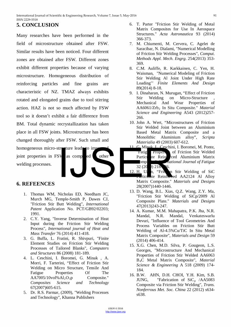
Huseyin Uzun [12] has been studied of “Friction stir welding of SiC particulate reinforced AA2124 aluminium alloy matrix composite”. He used a TiAlN- coated HSS tool for this experiment. He reported that optical micro-structure of as forged composite exhibited with uniform distribution of SiC reinforcement in AA2124 aluminium alloy matrix. A successful butt joint with selected parameters has been generated by FSW. He named the macrostructure as onion rings which have been appeared on the surface after FSW. He also certified the presence of four different zones as parent material, heat affected zone, thermo -mechanically affected zone and weld zone. There was a 90o rotation of matrix grains ad SiC particle free regions has been noticed within TMAZ. As like others he also concluded that there was no such difference in microstructure of BM and HAZ. He reported that high deformation and stirring action of tool has been resulted as homogeneous distribution of SiC particles within the weld zone. With the help of EDX analysis and SEM he told the presence of two types of particles- fine particles from 0.05 to 0.4 micro in size and coarser particles from 1 to 5 micron in size. He reported cracking of some coarser SiC particles in weld nugget by using SEM observation. He founded banded micro-structure of fine segregated SiC particle grains by optical view (Fig. 4.3). This banding exhibited the alternate layers of low and high fine SiC particle’s density which was reported
maximum at the pin’s root and mid thickness of FSW.
FIGURE 4.3: Low and high magnification micrographs of banded microstructure consisting segregated fine SiC particles in weld nugget. [12]
D. Wang. et al. [13] has represented the “Friction stir welding of SiCp/2009Al composite plate”. He used an ultra-hard material cylindrical tool for this purpose. He reported that a successful joint has been obtained by using an ultra-hard material tool in friction welding. Semi-circular rings on the upper surface of metal also notified by him as like others. He reported that there was a homogeneous distribution of SiC particles within the nugget zone after FSW. Sic particles have been flowed and rotated with matrix due to tool stirring action. There was no effect of T4 treatment on distribution of SiC particles. BSE images have cleared out that that amount of Al2Cu phase in NZ was lower as compared to B. He stated that after T4 treatment Al2Cu phase got dissolute within the matrix.
Anand Kumar et al. [14] has been studied the “Influence of tool geometries and process variables on friction stir butt welding of Al-4.5% Cu/TiC in situ metal matrix composites”. He used a cylindrical tool having titanium probe hardened by oxyacetylene flame followed by quenching. He quantified the presence of four different zones after FSW. He encountered that reinforcement present in needle shape within the HAZ. SZ as characterized by severely deformed and dynamically recrystallized region. Needles
IJSER

International Journal of Scientific & Engineering Research, Volume 7, Issue 5, May-2016 90 ISSN 2229-5518
IJSER © 2016 http://www.ijser.org
like reinforcement have been broken down by tool stirring action and distributed as very fine intermixed particles throughout the matrix of SZ. TMAZ also has been seen with very small needle like reinforcement.
X. G. Chen et al. [15] has been studied the “Microstructure and mechanical properties of friction stir welded AA6063-B4C metal matrix composites”. He casted-off a conical unthreaded tool made of AISI 4340 steel. He notified a homogeneous dispersal of B4C particles within SZ and low amount of clusters present compared to BM. After FSW fragmentation and redistribution of reaction induced particles and intermetallic particles have been noticed around B4C particles within SZ, Fig. 4.4. No fragmentation of intermetallic phase has been shown within HAZ and TMAZ. There was a decrement in grain size from 50 to 13 µm size has been noticed in NZ after FSW. After T6 treatment an abnormal grain growth has been noticed within SZ up-to 940 µm.
FIGURE 4.4: SEM micrographs on AA6063 + 10.5 % B4C. [15]
Byung-Wook AHN et al. [16] has been studied the “Fabrication of SiCp / AA5083 composite via friction stir welding”. He described the smaller grain size of matrix after FSW as pinning effect of particles. Hard reinforcing particles which were present in hot deformed material pin the movement of grain boundary and retarded the grain growth after dynamic recrystallization.
K. Kalaiselvan et al. [17] has been studied “Role of friction stir welding parameters on tensile
strength of AA6061-B4C composite joints”. He used a square pin profile tool made of high carbon and high chromium steel with 62 HRC oil hardened. He notified the presence of four different zones NZ, TMAZ, HAZ and BM respectively (Fig. 4.5). He reported that there was no significant difference has been noted between the microstructure of HAZ and BM. TMAZ has elongated grains. Grain refinement of matrix and reduction in B4C size both were noticed after FSW in NZ. He concluded that during FSW process SZ has been subjected to severe plastic deformation and material flow.
FIGURE 4.5: Optical micrographs of transverse section of castA6061-B4C MMCs (a) BM (b) HAZ, (c) TMAZ, (d)
WN. [17]
G.J. Fernandez et al. [18] had been studied the
characterization of tool wear and weld
optimization in FSW of cast aluminium
359+20% SiC metal matrix composite. It was
clear from microstructure that grain size of
nugget zone had been reduced compare to base
material. Grain size had been reduced 3µm in
nugget zone from 6µm in base material due to
dynamic recrystallization.
IJSER
International Journal of Scientific & Engineering Research, Volume 7, Issue 5, May-2016 91 ISSN 2229-5518
IJSER © 2016 http://www.ijser.org
5. CONCLUSION
Many researches have been performed in the
field of microstructure obtained after FSW.
Similar results have been noticed. Four different
zones are obtained after FSW. Different zones
exhibit different properties because of varying
microstructure. Homogeneous distribution of
reinforcing particles and fine grains are
characteristic of NZ. TMAZ always exhibits
rotated and elongated grains due to tool stirring
action. HAZ is not so much affected by FSW
tool so it doesn’t exhibit a fair difference from
BM. Total dynamic recrystallization has taken
place in all FSW joints. Microstructure has been
changed thoroughly after FSW. Such small and
homogeneous micro-structure leads to improved
joint properties in FSW as compared to other
welding processes.
6. REFEENCES
1. Thomas WM, Nicholas ED, Needham JC, Murch MG, Temple-Smith P, Dawes CJ, "Friction Stir Butt Welding", International Patent Application No. PCT/GB92/02203; 1991.
2. C.Y. Yang, "Inverse Determination of Heat Input during the Friction Stir Welding Process", International journal of Heat and Mass Transfer 76 (2014) 411-418.
3. G. Buffa, L. Fratini, R. Shivpuri, "Finite Element Studies on Friction Stir Welding Processes of Tailored Blanks", Computers and Structures 86 (2008) 181-189.
4. L. Ceschini, I. Boromei, G. Minak , A. Morri, F. Tarterini, “Effect of Friction Stir Welding on Micro Structure, Tensile And Fatigue Properties Of The AA7005/10vol%Al2O3p Composite." Composites Science and Technology 67(2007)605-615.
5. Dr. R.S. Parmar, (2009), "Welding Processes and Technology", Khanna Publishers
6. T. Parter "Friction Stir Welding of Metal Matrix Composites for Use In Aerospace Structures." Acta Astronautica 93 (2014) 366-373.
7. M. Chiumenti, M. Cervera, C. Agelet de Saracibar, N. Dialami, "Numerical Modelling of Friction Stir Welding Processes", Comput. Methods Appl. Mech. Engrg. 254(2013) 353-369.
8. C.M. Auliffe, R. Karkkainen, C. Yen, H. Waisman, "Numerical Modeling of Friction Stir Welding Al Joint Under High Rate Loading’’ Finite Elements And Design 89(2014) 8-18.
9. I. Dinaharan, N. Murugan, “Effect of Friction Stir Welding on Micro-Structure , Mechanical And Wear Properties of AA6061/Zrb2 In Situ Composite." Material Science and Engineering A543 (2012)257-266.
10. John A. Wert, “Microstructures of Friction Stir Welded Joint between an Aluminium Based Metal Matrix Composite and a Monolithic Aluminium alloy”, Scripta Materialia 49 (2003) 607-612.
11. G. Minak, L. Ceschini, I. Boromei, M. Ponte, "Fatigue Properties of Friction Stir Welded Particulate Reinforced Aluminium Matrix Composite", International Journal of Fatigue 32 (2010) 218-226.
12. H. Uzun, “Friction Stir Welding of SiC Particulate Reinforced AA2124 Al Alloy Matrix Composite." Materials and Designs 28(2007)1440-1446.
13. D. Wang, B.L. Xias, Q.Z. Wang, Z.Y. Ma, "Friction Stir Welding of SiCp/2009 Al Composite Plate." Materials and Designs 47(2013)243-247.
14. A. Kumar, M.M. Mahapatra, P.K. Jha, N.R. Mandal, N.R. Mandal, Venkateswarlu Devuri, "Influence of Tool Geometries And Process Variables on Friction Stir Butt Welding of Al-4.5%Cu/TiC In Situ Metal Matrix Composite", Materials and Design 59 (2014) 406-414.
15. X.G. Chen, M.D. Silva, P. Gougeon, L.S. Georges, "Microstructure And Mechanical Properties of Friction Stir Welded AA6063 B4C Metal Matrix Composite", Material Science & Engineering A 518 (2009) 174-184.
16. B.W. AHN, D.H. CHOI, Y.H. Kim, S.B. JUNG, "Fabrication of SiCp /AA5083 Composite via Friction Stir Welding", Trans. Nonferrous Met. Soc. China 22 (2012) s634-s638.
IJSER

International Journal of Scientific & Engineering Research, Volume 7, Issue 5, May-2016 92 ISSN 2229-5518
IJSER © 2016 http://www.ijser.org
17. K. Kalaiselvan, N. Murugan, "Role of Friction Stir Welding Parameters on Tensile Strength of AA6061-B4C Composite Joint", Trans. Nonferrous Met. Soc. China23 (2013) 616-624.
18. G.J. Fernandez, L.E. Murr, "Characterization of Tool Wear And Welding Optimization In Friction Stir Welding of Cast Aluminium Alloy 359+20% SiC Metal Matrix Composite", Materials Characterization 52 (2004) 65-75.
IJSER