Embed Size (px)
Citation preview
J. M. R. Malla et. al. / International Journal of New Technologies in Science and EngineeringVol. 1, Issue. 1, Jan. 2014, ISSN XXXX-XXXX
Available online @ www.ijntse.com 32
A Review on Direct Torque Control ofInduction Motor
Jagan Mohana Rao Malla and Manti Mariya DasEmail: [email protected]
Abstract: At present, induction motors are the dominant drives in various industries. It is quitecumbersome to control an induction motor (IM) because of its poor dynamic response incomparison to the DC motor drives. The central theme of Vector Control (VC) is to decouplethe stator current of the IM into two orthogonal components and is to control these twocomponents individually so as to achieve an independent control of flux and torque of the IM.VC is still very complex to implement. Direct Torque Control (DTC) is an improvised VCmethod. With the DTC scheme employing a Voltage Source Inverter, it is possible to controldirectly the stator flux linkage and the electromagnetic torque by the optimum selection ofinverter switching vectors. The modeling of an IM drive employing DTC with application offuzzy is performed in this article, it is better to understand the DTC and its difficulties. Thereference voltage vector is then realized using a voltage vector modulator. Several variations ofDTC-SVM have been proposed and discussed in the literature. The work of this review paperis to study, evaluate and compare the various techniques of the DTC-SVM applied to theInduction Motor.
Keywords: Induction Motor Drive, Modeling of Induction Motor, Vector Control, Field OrientControl, Direct Torque Control, and Fuzzy Applications.
1. INTRODUCTIONThe history of electrical motors goes back as far as 1820, when Hans Christian Oersted
discovered the magnetic effect of an electric current. One year later, Michael Faraday discovered theelectromagnetic rotation and built the first primitive D.C. motor. Faraday went on to discoverelectromagnetic induction in 1831, but it was not until 1883 that Tesla invented the A.C.asynchronous motor [1]. Currently, the main types of electric motors are still the same, DC, ACasynchronous and synchronous, all based on Oested, Faraday and Tesla’s theories developed anddiscovered more than a hundred years ago.
An IM is a type of asynchronous AC motor where power is supplied to the rotating device bymeans of electromagnetic induction [2-5]. Induction motors are widely used, especially polyphaseinduction motors, which are frequently used in industrial drives. These facts are due to the inductionmotors advantages over the rest of the motors. Most of the industrial motor applications use ACinduction motors. The reasons for this include high robustness, reliability, low price and highefficiency [2-8].
2. PRINCIPLE OF OPERATION AND COMPARISON TO SYNCHRONOUS MOTORSA 3-phase power supply provides a rotating magnetic field in an IM. The basic difference
between an IM and a synchronous AC motor is that in the latter a current is supplied onto the rotor.This then creates a magnetic field which, through magnetic interaction, links to the rotating magneticfield in the stator which in turn causes the rotor to turn. It is called synchronous because at steadystate the speed of the rotor is the same as the speed of the rotating magnetic field in the stator. Byway of contrast, the IM does not have any direct supply onto the rotor; instead, a secondary current isinduced in the rotor [2, 9]. This changing magnetic field pattern can induce currents in the rotorconductors. These currents interact with the rotating magnetic field created by the stator and the rotorwill turn [10].
J. M. R. Malla et. al. / International Journal of New Technologies in Science and EngineeringVol. 1, Issue. 1, Jan. 2014, ISSN XXXX-XXXX
Available online @ www.ijntse.com 33
This difference between the speed of the rotor and speed of the rotating magnetic field in thestator is called slip. The three phase AC IM and is the most widely used machine. Because it ishaving the characteristic features Simple and rugged construction, Low cost and minimummaintenance, High reliability and sufficiently high efficiency, Needs no extra starting motor andneed not be synchronized, and an IM has basically two parts: Stator and Rotor [10].2.1. APPLICATIONS
A wide variety of induction motors are available and are currently in use throughout a rangeof industrial applications. Single phase induction motors are widely used, due to their simplicity,strength and high performance. They are used in household appliances, such as refrigerators, airconditioners, hermetic compressors, washing machines, pumps, fans, as well as in some industrialapplications. Before the days of power electronics, a limited speed control of IM was achieved byswitching the three-stator windings from delta connection to star connection, allowing the voltage atthe motor windings to be reduced [1-20].2.2. VARIABLE-FREQUENCY DRIVES (VFD)
A VFD can easily start a motor at a lower frequency than the AC line, as well as a lowervoltage, so that the motor starts with full rated torque and with no inrush of current. The rotorcircuit's impedance increases with slip frequency, which is equal to supply frequency for a stationaryrotor, so running at a lower frequency actually increases torque [21-23]. Industries have manyapplications, where variable operating speed is a prime requirement. Principal benefits of variablespeed drives in industrial applications are that they allow the drive speed and torque to be adjusted tosuit the process requirements. In many applications, operating the plant at a reduced speed when fulloutput is not needed produces a further important benefit: energy savings and reduced cost [21].Whereas infinitely variable speed drives with good performances for DC motors already existed.These drives not only permitted the operation in four quadrants but also covered a wide power range.Moreover, they had a good efficiency, and with a suitable control even a good dynamic response. Itsmain drawback was the compulsory requirement of brushes [10].
The various methods of speed control of squirrel cage IM through semiconductor devices aregiven in [2, 9-20] as under: Scalar control, Vector control (Field-Oriented Control, FOC), DirectTorque Control (DTC) and DTC with SVM & Fuzzy based control. These controllers are depends onhow inverters can be controlled, mostly multilevel inverters are using in industries due to theiradvantages [21-45].
Scalar controllers: Despite the fact that “Voltage-Frequency” (V/F) is the simplest controller, itis the most widespread, being in the majority of the industrial applications [2]. It is known as a scalarcontrol and acts by imposing a constant relation between voltage and frequency, so as to give nearlyconstant flux over wide range of speed variation [9]. More over Constant voltage/hertz control keepsthe stator flux linkage constant in steady state without maintaining decoupling between the flux andtorque [2]. However, this controller does not achieve a good accuracy in both speed and torqueresponses, mainly due to the fact that the stator flux and torque are not directly controlled. Eventhough, as long as the parameters are identified, the accuracy in the speed can be 2% (expect in avery low speed), and the dynamic response can be approximately around 50ms [2, 9].
Vector controllers: In 1971, Blaschke propose a scheme which aims as the control of an IMlike a separately excited dc motor, called field oriented control, VC, or Trans vector control [46-48].In this scheme the IM analyzed from a synchronously rotating reference frame where all fundamentalvariables appears to be dc ones. The torque and flux component of currents are identified andcontrolled independently to achieve good dynamic response [46, 47]. The most widespreadcontrollers of this type are the ones that use vector transform such as either Park or Ku. Howeverthere is a necessity of transforming the variables in the synchronously rotating reference frame tostator reference frame to affect the control of actual currents/voltages [47]. Additionally thetransformation also needs the approximate flux vector angle, where is either calculated slip angle ormeasured rotor angle as indirect VC or by estimating the flux angle directly by employing a flux
J. M. R. Malla et. al. / International Journal of New Technologies in Science and EngineeringVol. 1, Issue. 1, Jan. 2014, ISSN XXXX-XXXX
Available online @ www.ijntse.com 34
observer as in direct VC [47]. Its accuracy can reach values such as 0.5% regarding the speed and2% regarding the torque, even when at standstill. The main disadvantages are the huge computationalcapability required and the compulsory good identification of the motor parameters.
Recently advanced control strategies for PWM inverter fed IM drives have been developedbased on the space vector approach, where the IM can be directly and independently controlledwithout any co-ordination transformation [48]. One of the emerging methods in this perspective isthe direct torque and flux control (DTFC). In DTFC, the motor torque and the flux are calculatedfrom the primary variables, and they are controlled directly and independently by selecting optimuminverter switch modes [2-52]. This control results in quick torque response in the transient operationand improvement in the steady state efficiency [14]. Its main characteristic is the good performance,obtaining results as good as the classical vector control but with several advantages based on itssimpler structure and control diagram.
DTC is said to be one of the future ways of controlling the IM in four quadrants. In DTC it ispossible to control directly the stator flux and the torque by selecting the appropriate inverter state[46, 54]. DTC main features are direct control of flux and torque, indirect control of stator currentsand voltages, approximately sinusoidal stator fluxes and stator currents, and High dynamicperformance even at stand still [53, 54]. DTC have several advantages like, Decoupled control oftorque and flux, Absence of co-ordinate transforms, Absence of voltage modular block, Absence ofmechanical transducers, Current regulator, PWM pulse generation, PI control of flux and torque andco-ordinate transformation is not required, Very simple control scheme and low computational time,and Reduced parameter sensitivity and Very good dynamic properties as well as other controllerssuch as PID for motor flux and torque, and Minimal torque response time even better than the VCs[53, 54]. However, some disadvantages are also present such as: Possible problems during starting,Requirement of torque and flux estimators, implying the consequent parameters identification, andInherent torque and stator flux ripple [53-54]. Although, some disadvantages are: High torque ripplesand current distortions, Low switching frequency of transistors with relation to computation time,Constant error between reference and real torque [3]. After this, comparison of variable speed drivesis given. The aim being to find even simpler methods of speed control for induction machines onemethod, which is popular at the moment, is DTC.
Initially the theory of induction machine model is given. The understanding of this model ismandatory to understand both the control strategies (i.e. FOC and DTC). DTC drives utilizinghysteresis comparators suffer from high torque ripple and variable switching frequency. Straightlyspeaking, Major drawback of Classical DTC is high torque & flux ripples. The most commonsolution to this problem is to use fuzzy applications with Space Vector Modulation (SVM) or usingmultilevel inverter [2, 3]. In this Paper the author briefly explained about two-fuzzy controller alongwith the SVM technique is applied to two level inverter. Before going to DTC, first we study aboutthe mathematical background of DTC.
3. INDUCTION MOTOR MATHEMATICAL MODELThe steady-state model and equivalent circuit are useful for studying the performance of
machine in steady state. This implies that all electrical transients are neglected during load changesand stator frequency variations. The dynamic model of IM is derived by using a two-phase motor indirect and quadrature axes [55]. This approach is desirable because of the conceptual simplicityobtained with the two sets of the windings, one on the stator and the other on the rotor. Theequivalence between the three-phase and two-phase machine models is derived from the simpleobservation. The concept of power invariance is introduced [2, 3, 8]. The reference frames arechosen to arbitrary and particular cases such as stationary, rotor, and synchronous reference frames,are simple instances of the general case. The space-phasor model is derived from the dynamic modelin direct and quadrature axes [55].3.1 DYNAMIC d-q MODEL
J. M. R. Malla et. al. / International Journal of New Technologies in Science and EngineeringVol. 1, Issue. 1, Jan. 2014, ISSN XXXX-XXXX
Available online @ www.ijntse.com 35
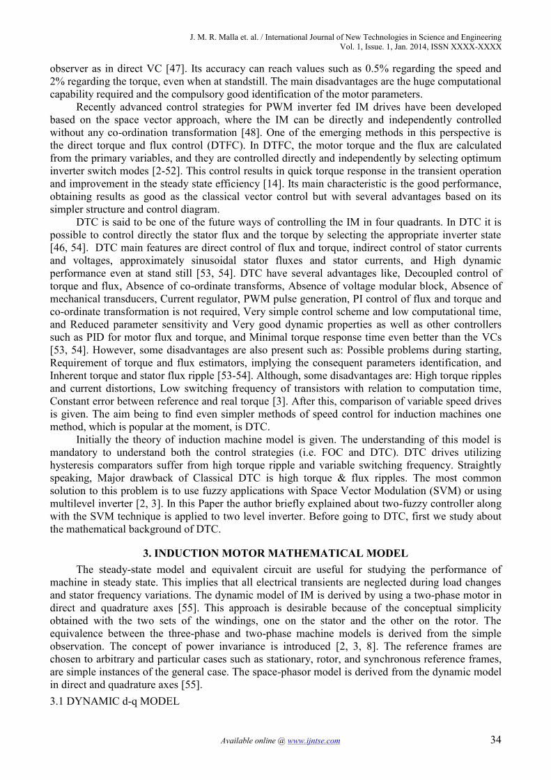
The assumptions are made to derive the dynamic model as uniform air gap, balanced rotor andstator windings, with sinusoidal distributed mmf, inductance vs. rotor position in sinusoidal, andSaturation and parameter changes are neglected. The dynamic performance of an AC machine issomewhat complex because the three-phase rotor windings move with respect to the three-phasestator windings as shown in Fig 1(a). Basically, it can be looked on as a transformer with a movingsecondary, where the coupling coefficients between the stator and rotor phases change continuouslywith the change of rotor position correspond to rotor direct and quadrature axes [2-4, 7, 8]. Notethat a three-phase machine can be represented by an equivalent two-phase machine as shown in Fig1(b), where ds ~ qs correspond to stator direct and quadrature axes, and d r ~q r is corresponding torotor.
Fig 1: (a) Coupling effect in three-phase stator and rotor windings of motor; (b) Equivalent two-phasemachine.
Although it is somewhat simple, the problem of time-varying parameters still remains. R.H.Park, in the 1920s, proposed a new theory of electric machine analysis to solve this problem.Essentially, he transformed or referred, the stator variables to a synchronously rotating referenceframe fixed in the rotor [56]. With such a transformation (called Park’s transformation), he showedthat all the time-varying inductances that occur due to an electric circuit in relative motion andelectric circuits with varying magnetic reluctances can be eliminated [3,7]. Later, in the 1930s, H. C.Stanley showed that time- varying inductances in the voltage equations of an induction machine dueto electric circuits in relative motion can be eliminated by transforming the rotor variables tovariables associated with fictitious stationary windings. Later, G. Kron proposed a transformation ofboth stator and rotor variables to a synchronously rotating reference frame that moves with therotating magnetic field. D. S. Brereton proposed a transformation of stator variables to a rotatingreference frame that is fixed on the rotor. In fact, it was shown later by Krause and Thomas that time-varying inductances can be eliminated by referring the stator and rotor variables to a commonreference frame which may rotate at any speed.3.2. AXES TRANSFORMATION
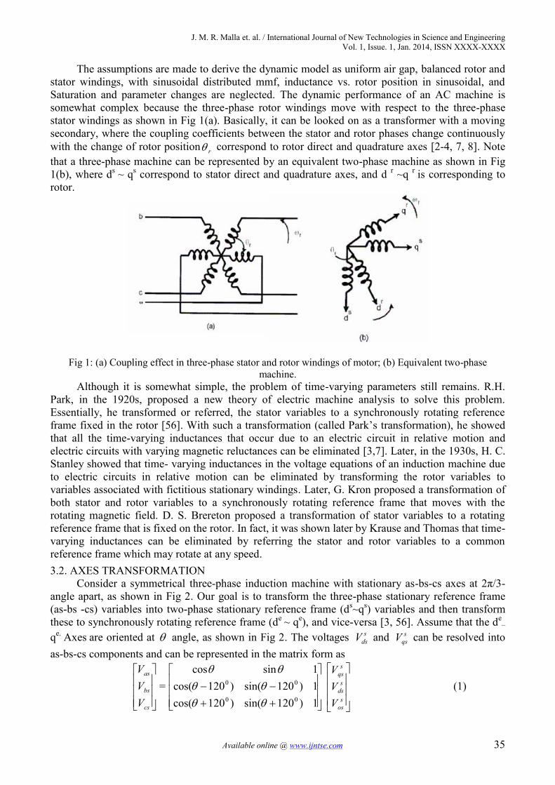
Consider a symmetrical three-phase induction machine with stationary as-bs-cs axes at 2π/3-angle apart, as shown in Fig 2. Our goal is to transform the three-phase stationary reference frame(as-bs -cs) variables into two-phase stationary reference frame (ds~qs) variables and then transformthese to synchronously rotating reference frame (de ~ qe), and vice-versa [3, 56]. Assume that the de
–
qe. Axes are oriented at angle, as shown in Fig 2. The voltages and can be resolved intoas-bs-cs components and can be represented in the matrix form as
= (1)
r
sdsV s
qsV
cs
bs
as
VVV
1)120sin()120cos(1)120sin()120cos(1sincos
00
00
sos
sds
sqs
VVV

J. M. R. Malla et. al. / International Journal of New Technologies in Science and EngineeringVol. 1, Issue. 1, Jan. 2014, ISSN XXXX-XXXX
Available online @ www.ijntse.com 36
The corresponding inverse relation is.
= (2)
Where is added as the zero sequence component, which may or may not be present. Thecurrent and flux linkages can be transformed by similar equations. It is convenient to set = 0, sothat the qs axis is aligned with the as-axis, the transformation relations can be simplified by ignoringzero sequence. Fig 3 shows the synchronously rotating de- q e, which rotates at synchronous speed
with respect to the ds-qs axes and the angle the two-phase de- qs windings aretransformed into the hypothetical windings mounted on the de-qe axes [3]. The voltages on the ds-qs
axes can be converted (or resolved) into the de-qe frame as follows:(3)
(4)For convenience, the superscript e has been dropped from now on from the synchronously
rotating frame parameters. Again, resolving the rotating frame parameters into a stationary frame, therelations are.
(5)
(6)The qe -de components can also be combined into a vector form:
(7)
Or inversely(8)
Note that the vector magnitudes in stationary and rotating frames are equal, that is,
(9)
Fig 2. Stationary frame a~b~c to ds~qs axes transformation.
sos
sds
sqs
VVV
32
5.05.05.0)120sin()120sin(sin)120cos()120cos(cos
00
00
cs
bs
as
VVV
sosV
e .tee
es
dses
qsqs VVV sincos
es
dses
qsds VVV cossin
edseqss
qs VVV sincos
edseqss
ds VVV cossin
ee jjsds
sqs
es
dses
qses
dses
qsdsqse
qds
eVejVV
VVjVVjVVV
)(
)cossin()sincos(
ejdsqs
sds
sqs ejVVjVVV )(
22ˆdsqsm VVVV
J. M. R. Malla et. al. / International Journal of New Technologies in Science and EngineeringVol. 1, Issue. 1, Jan. 2014, ISSN XXXX-XXXX
Available online @ www.ijntse.com 37
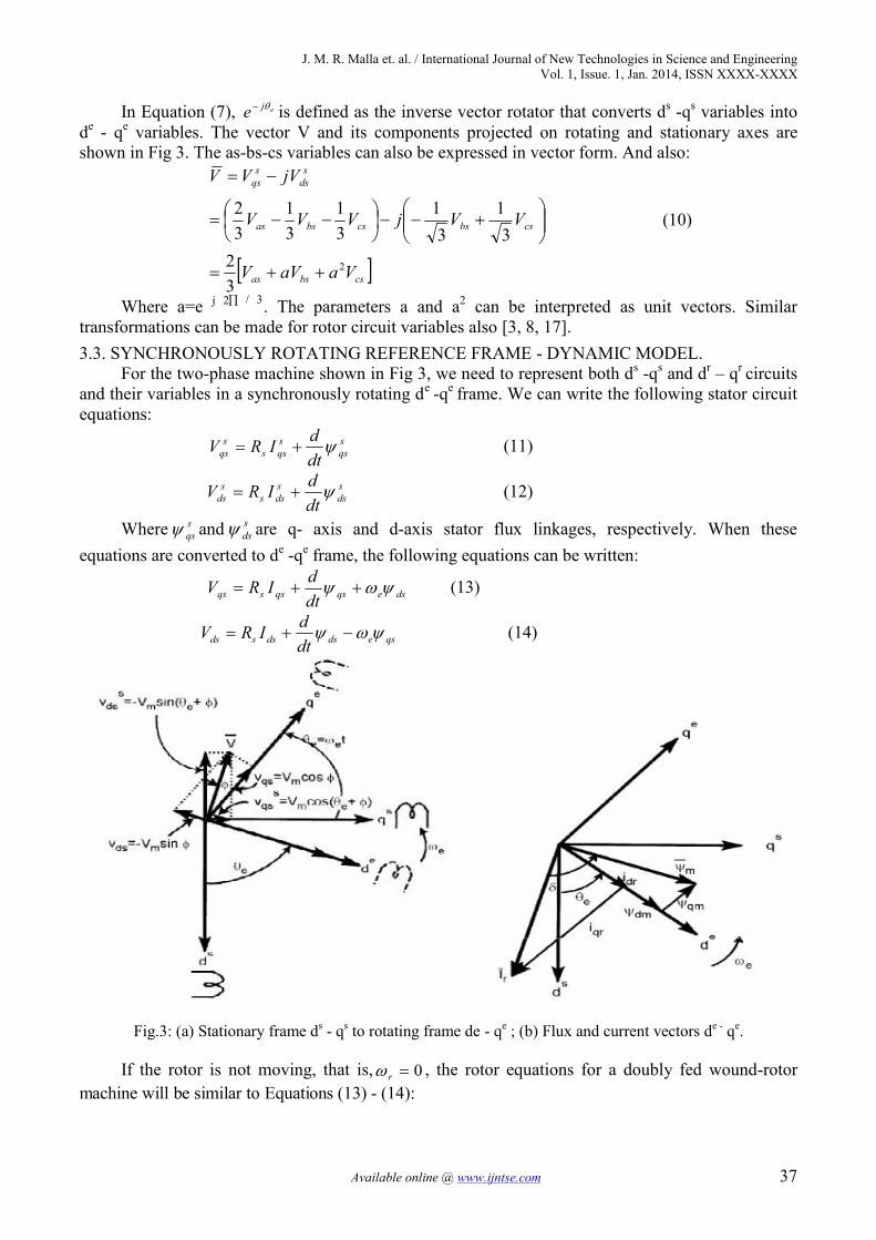
In Equation (7), eje is defined as the inverse vector rotator that converts ds -qs variables intode - qe variables. The vector V and its components projected on rotating and stationary axes areshown in Fig 3. The as-bs-cs variables can also be expressed in vector form. And also:
(10)
Where a=e j 2∏ / 3. The parameters a and a2 can be interpreted as unit vectors. Similartransformations can be made for rotor circuit variables also [3, 8, 17].3.3. SYNCHRONOUSLY ROTATING REFERENCE FRAME - DYNAMIC MODEL.
For the two-phase machine shown in Fig 3, we need to represent both ds -qs and dr – qr circuitsand their variables in a synchronously rotating de -qe frame. We can write the following stator circuitequations:
(11)
sds
sdss
sds dt
dIRV (12)
Where and are q- axis and d-axis stator flux linkages, respectively. When theseequations are converted to de -qe frame, the following equations can be written:
(13)
qsedsdssds dtdIRV (14)
Fig.3: (a) Stationary frame ds - qs to rotating frame de - qe ; (b) Flux and current vectors de - qe.
If the rotor is not moving, that is, , the rotor equations for a doubly fed wound-rotormachine will be similar to Equations (13) - (14):
csbsas
csbscsbsas
sds
sqs
VaaVV
VVjVVV
jVVV
2
32
31
31
31
31
32
sqs
sqss
sqs dt
dIRV
sqs
sds
dseqsqssqs dtdIRV
0r
J. M. R. Malla et. al. / International Journal of New Technologies in Science and EngineeringVol. 1, Issue. 1, Jan. 2014, ISSN XXXX-XXXX
Available online @ www.ijntse.com 38
(15)
qredrdrrdr dtdiRV (16)
The rotor actually moves at speed r , the d - q axes fixed on the rotor move at a speed e - rrelative to the synchronously rotating frame. Therefore, rotor equations should be modified as.
(17)
(18)
The de -qe dynamic model equivalent circuits that satisfy Equations (13), (14) and (17), (18). Aspecial advantage of the de -qe dynamic model of the machine is that all the sinusoidal variables instationary frame appear as dc quantities in synchronous frame. The flux linkage expressions in termsof the currents can be written from Fig 3(b) as follows:
(19)
)( qrqsmqrlrqr iiLiL (20)
)( qrqsmqm iiL (21)
)( drdsmdslsds iiLiL (22))( drdsmdrlrdr iiLiL (23)
)( drdsmdm iiL (24)Combining the above expressions with Equations (13), (14), (17) and (18), the electrical
transient model in terms of voltages and currents can be given in matrix form as
(25).
Where S is Laplace operator. For a cage motor, Vrq=Vdr= 0. If the speed is consideredconstant. Then, knowing the inputs Vsq, Vsd and , the currents iqs, ids, iqr and idr can be solved fromEquation (25). If the machine is fed by current source, iqs, ids and are independent. Then thedependent variables Vsq,Vsd, iqr and idr can be solved from Equation (25). The speed in Equation(25) cannot normally be treated as a constant. It can be related to the torques as
(26)
Where TL = load torque, J = rotor inertia, and = mechanical speed. Often, for compactrepresentation, the machine model and equivalent circuits are expressed in complex form [3].Multiplying Equation (14) by –j and adding with Equation (13) gives.
(27)
Or (28)
Similarly, the rotor equations (17)-(18) can be combined to represent
qdrreqdrqdrrqdr jdtdiRV )( (29)
dreqrqrrqr dtdiRV
drreqrqrrqr dtdiRV )(
qrredrdrrdr dtdiRV )(
)( qrqsmqslsqs iiLiL
dr
qr
ds
qs
rrrremmre
rrerrmrem
mmessse
memsess
dr
qr
ds
qs
iiii
SLRLSLLLSLRLSL
SLLSLRLLSLLSLR
VVVV
)()()()(
r
e
e
r
dtdJ
PT
dtdJTT r
Lm
Le 2
m
)()()( dsqsedsqsdsqssdsqs jjjdtdjiiRjVV
qdsreqdsqdssqds jdtdiRV )(

J. M. R. Malla et. al. / International Journal of New Technologies in Science and EngineeringVol. 1, Issue. 1, Jan. 2014, ISSN XXXX-XXXX
Available online @ www.ijntse.com 39
Where Vqdr=0. Therefore, the steady-state equations can be derived as(30)
(31)
If the parameter Rm is neglected. We know that
sin22
3rme IPT
(32)
From Equation (32), the torque can be generally expressed in the vector form as
(33)
drqmqrdme IiPT
223
(34)
Some other torque expressions can be derived easily as follows:
dsqmqsdme IiPT
223
(35)
dsqsqsdse IiPT
223
(36)
)(22
3qrdsdrqsme iiiiLPT
(37)
)(22
3drqrqrdre IiPT
(38)
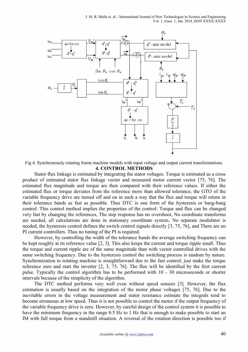
Equations (25), (26), and (37) give the complete model of the electro-mechanical dynamics ofan IM in synchronous frame. Fig 4 shows the block diagram of the machine model along with inputvoltage & output current transformation [2, 8] and resolving variables into dqe components.Renewable energy based water supply system is one of the application [57-74]. In irrigation anddrinking water supply, mostly we are using induction motors; hence study of control of inductionmotor is necessary.
sesss jIRV
rerr jI
SR
0
rme IxPT
223
J. M. R. Malla et. al. / International Journal of New Technologies in Science and EngineeringVol. 1, Issue. 1, Jan. 2014, ISSN XXXX-XXXX
Available online @ www.ijntse.com 40
Fig 4. Synchronously rotating frame machine models with input voltage and output current transformations.4. CONTROL METHODS
Stator flux linkage is estimated by integrating the stator voltages. Torque is estimated as a crossproduct of estimated stator flux linkage vector and measured motor current vector [75, 76]. Theestimated flux magnitude and torque are then compared with their reference values. If either theestimated flux or torque deviates from the reference more than allowed tolerance, the GTO of thevariable frequency drive are turned off and on in such a way that the flux and torque will return intheir tolerance bands as fast as possible. Thus DTC is one form of the hysteresis or bang-bangcontrol. This control method implies the properties of the control: Torque and flux can be changedvery fast by changing the references, The step response has no overshoot, No coordinate transformsare needed, all calculations are done in stationary coordinate system, No separate modulator isneeded, the hysteresis control defines the switch control signals directly [3, 75, 76], and There are noPI current controllers. Thus no tuning of the PI is required.
However, by controlling the width of the tolerance bands the average switching frequency canbe kept roughly at its reference value [2, 3]. This also keeps the current and torque ripple small. Thusthe torque and current ripple are of the same magnitude than with vector controlled drives with thesame switching frequency. Due to the hysteresis control the switching process is random by nature.Synchronization to rotating machine is straightforward due to the fast control; just make the torquereference zero and start the inverter [2, 3, 75, 76]. The flux will be identified by the first currentpulse. Typically the control algorithm has to be performed with 10 - 30 microseconds or shorterintervals because of the simplicity of the algorithm.
The DTC method performs very well even without speed sensors [3]. However, the fluxestimation is usually based on the integration of the motor phase voltages [75, 76]. Due to theinevitable errors in the voltage measurement and stator resistance estimate the integrals tend tobecome erroneous at low speed. Thus it is not possible to control the motor if the output frequency ofthe variable frequency drive is zero. However, by careful design of the control system it is possible tohave the minimum frequency in the range 0.5 Hz to 1 Hz that is enough to make possible to start anIM with full torque from a standstill situation. A reversal of the rotation direction is possible too if
J. M. R. Malla et. al. / International Journal of New Technologies in Science and EngineeringVol. 1, Issue. 1, Jan. 2014, ISSN XXXX-XXXX
Available online @ www.ijntse.com 41
the speed is passing through the zero range rapidly enough to prevent excessive flux estimatedeviation [77, 78]. If continuous operation at low speeds including zero frequency operation isrequired, a position sensor can be added to the DTC system [77-79].
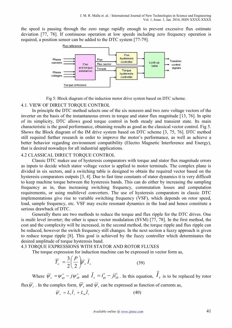
Fig 5: Block diagram of the induction motor drive system based on DTC scheme.4.1. VIEW OF DIRECT TORQUE CONTROL
In principle the DTC method selects one of the six nonzero and two zero voltage vectors of theinverter on the basis of the instantaneous errors in torque and stator flux magnitude [13, 76]. In spiteof its simplicity, DTC allows good torque control in both steady and transient state. Its maincharacteristic is the good performance, obtaining results as good as the classical vector control. Fig 5.Shows the Block diagram of the IM drive system based on DTC scheme [3, 75, 76]. DTC methodstill required further research in order to improve the motor’s performance, as well as achieve abetter behavior regarding environment compatibility (Electro Magnetic Interference and Energy),that is desired nowadays for all industrial applications.4.2 CLASSICAL DIRECT TORQUE CONTROL
Classic DTC makes use of hysteresis comparators with torque and stator flux magnitude errorsas inputs to decide which stator voltage vector is applied to motor terminals. The complex plane isdivided in six sectors, and a switching table is designed to obtain the required vector based on thehysteresis comparators outputs [3, 4]. Due to fast time constants of stator dynamics it is very difficultto keep machine torque between the hysteresis bands. This can do either by increasing the samplingfrequency as in, thus increasing switching frequency, commutation losses and computationrequirements, or using multilevel converters. The use of hysteresis comparators in classic DTCimplementations give rise to variable switching frequency (VSF), which depends on rotor speed,load, sample frequency, etc. VSF may excite resonant dynamics in the load and hence constitute aserious drawback of DTC.
Generally there are two methods to reduce the torque and flux ripple for the DTC drives. Oneis multi level inverter; the other is space vector modulation (SVM) [77, 78]. In the first method, thecost and the complexity will be increased, in the second method, the torque ripple and flux ripple canbe reduced, however the switch frequency still changes. In the next section a fuzzy approach is givento reduce torque ripple [8]. This goal is achieved by the fuzzy controller which determinates thedesired amplitude of torque hysteresis band.4.3 TORQUE EXPRESSIONS WITH STATOR AND ROTOR FLUXES
The torque expression for induction machine can be expressed in vector form as,
223
sse IPT
(39)
Where sds
sqss j and
sds
sqss jiiI . In this equation, sI is to be replaced by rotor
flux r . In the complex form, s and r can be expressed as function of currents as,
rmsss ILIL (40)

J. M. R. Malla et. al. / International Journal of New Technologies in Science and EngineeringVol. 1, Issue. 1, Jan. 2014, ISSN XXXX-XXXX
Available online @ www.ijntse.com 42
smrrr ILIL (41)From equations 39, 40 and 41:
srsr
me LL
LPT '223
(42)
That is, the magnitude torque is
sin22
3' srsr
me LL
LPT
(43)
Where γ is the angle between the fluxes, indicating the vectors s , r , and sI for positivedeveloped torque. If the rotor flux remains constant and stator flux is changed incrementally by statorvoltage sV as shown and the corresponding change of γ angle is , the incremental torque eTexpression is given as
sin22
3'
ssr
sr
me LL
LPT (44)
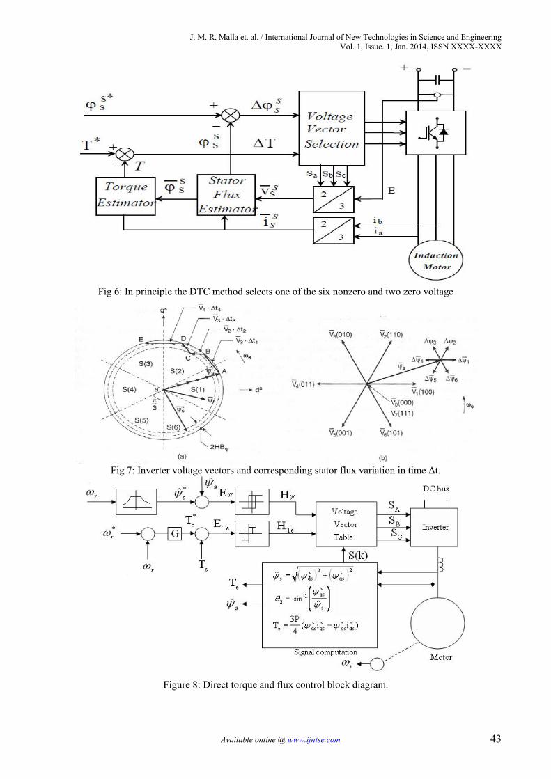
4.4 CONTROL STRATEGY OF DTCBlock diagram of the IM drive system based on DTC scheme is shown in Fig 6. The speed
control loop and the flux program as a function of speed are shown as usual and will not be
discussed. The command stator flux *ˆ s and torque*
eT magnitudes are compared with the respectiveestimated values and the errors are processed through hysteresis-band controllers, as shown [2]. Theflux loop controller has two levels of digital output according to the following relations:
for1 HBEH (45)
HBEH for1 (46)
Where HB2 = total hysteresis-band width controller. The circular trajectory of the command
flux vector*ˆ s with the hysteresis band rotates in an anti-clockwise direction as shown in Fig 7. The
actual stator flux s is constrained within the hysteresis band and it tracks the command flux in azigzag path. The torque control loop has three levels of digital output, which have the followingrelations [2]:
TeTeTe HBEH for1 (47)
TeTeTe HBEH for1 (48)for0 TeTeTeTe HBEHBH (49)
J. M. R. Malla et. al. / International Journal of New Technologies in Science and EngineeringVol. 1, Issue. 1, Jan. 2014, ISSN XXXX-XXXX
Available online @ www.ijntse.com 43
Fig 6: In principle the DTC method selects one of the six nonzero and two zero voltage
Fig 7: Inverter voltage vectors and corresponding stator flux variation in time Δt.
Figure 8: Direct torque and flux control block diagram.

J. M. R. Malla et. al. / International Journal of New Technologies in Science and EngineeringVol. 1, Issue. 1, Jan. 2014, ISSN XXXX-XXXX
Available online @ www.ijntse.com 44
The feedback flux and torque are calculated from the machine terminal voltages and currents.The signal computation block also calculates the sector number S(k) in which the flux vector s lies.There are six sectors (each /3 angle wide), as in Fig 7(a). The voltage vector table block in Fig 8receives the input signals ,, TeHH and S(k)and generates the appropriate control voltage vector(switching states) for the inverter by lookup table, which is shown in table 1 (the vector sign isdeleted) [2, 3]. The inverter voltage vector and a typical s are shown in Fig 7(b). Neglecting thestator resistance of the machine, we can write.
)( ss dtdV (50)
Or. tVss (51)
Which means that s can be changed incrementally by applying stator voltage sV for timeincrement Δt. The flux increment vector corresponding to each of six inverter voltage vectors isshown in Fig 7. The flux in machine is initially established to at zero frequency (dc) along the
trajectory OA shown in Figure 7. With the rated flux, the command torque is applied and the*
svector starts rotating [2, 3].
Table1: Switching table of inverter voltage vectors.HΨ HTe S(1) S(2) S(3) S(4) S(5) S(6)
1
1 V2 V3 V4 V5 V6 V1
0 V0 V7 V0 V7 V0 V7
-1 V6 V1 V2 V3 V4 V5
-1
1 V3 V4 V5 V6 V1 V2
0 V7 V0 V7 V0 V7 V0
-1 V5 V6 V1 V2 V3 V4
Table2: Flux and Torque variations due to applied voltage vector in.
Voltage vector V1 V2 V3 V4 V5 V6 V0 or V7
Ψs 0
Te
Table 1 applies the selected voltage vector, which essentially affects both the torque and fluxsimultaneously [2, 3]. The flux trajectory segments AB, BC, CD and DE by the respective voltagevectors 4343 and,,, VVVV are shown in Figure 7(a). The total and incremental torque due to sare explained in Fig 7(b). Note that the stator flux vector changes quickly by, but the r change is
J. M. R. Malla et. al. / International Journal of New Technologies in Science and EngineeringVol. 1, Issue. 1, Jan. 2014, ISSN XXXX-XXXX
Available online @ www.ijntse.com 45
very sluggish due to large time constant Tr. Since r is more filtered, it moves uniformly at
frequency ωe, whereas s movement is jerky. The average speed of both, however, remains thesame in the steady-state condition. Table2 summarizes the flux and torque change (magnitude anddirection) for applying the voltage vectors for the location of s shown in Fig 7(b) [2, 3]. The flux
can be increased by the 621 and,, VVV vectors, whereas it can be decreased by the 543 and,, VVVvectors [2]. Similarly, torque is increased by the 432 and,, VVV Vectors, but decreased by the
651 and,, VVV vectors. The zero vectors (V0 or V7) short-circuit the machine terminals and keepthe flux and torque unaltered. Due to finite resistance (Rs) drop, the torque and flux will slightlydecrease during the short-circuit condition.
Consider for example, an operation in sector S(2) as shown in Fig 7(a), where at point B, the
flux is too high and the torque is too low; that is, 1H and 1TeH . From table 1, voltage
V4 is applied to the inverter, which will generate the trajectory BC. At point C, 1H and
1TeH and this will generate the V3 vector from the table. The drive can easily operate in thefour quadrants, and speed loop and field-weakening control can be added, if desired [80]. The torqueresponse of the drive is claimed to be comparable with that of a vector-controlled drive [2].
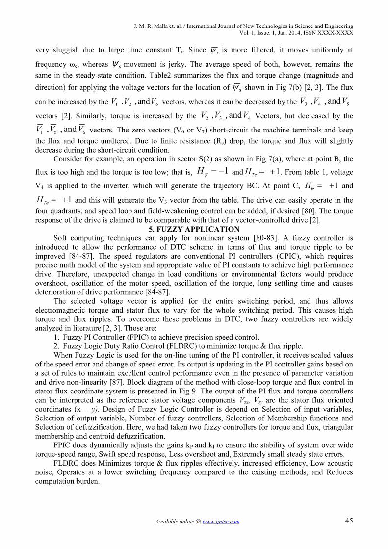
5. FUZZY APPLICATIONSoft computing techniques can apply for nonlinear system [80-83]. A fuzzy controller is
introduced to allow the performance of DTC scheme in terms of flux and torque ripple to beimproved [84-87]. The speed regulators are conventional PI controllers (CPIC), which requiresprecise math model of the system and appropriate value of PI constants to achieve high performancedrive. Therefore, unexpected change in load conditions or environmental factors would produceovershoot, oscillation of the motor speed, oscillation of the torque, long settling time and causesdeterioration of drive performance [84-87].
The selected voltage vector is applied for the entire switching period, and thus allowselectromagnetic torque and stator flux to vary for the whole switching period. This causes hightorque and flux ripples. To overcome these problems in DTC, two fuzzy controllers are widelyanalyzed in literature [2, 3]. Those are:
1. Fuzzy PI Controller (FPIC) to achieve precision speed control.2. Fuzzy Logic Duty Ratio Control (FLDRC) to minimize torque & flux ripple.When Fuzzy Logic is used for the on-line tuning of the PI controller, it receives scaled values
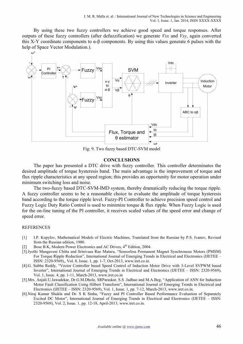
of the speed error and change of speed error. Its output is updating in the PI controller gains based ona set of rules to maintain excellent control performance even in the presence of parameter variationand drive non-linearity [87]. Block diagram of the method with close-loop torque and flux control instator flux coordinate system is presented in Fig 9. The output of the PI flux and torque controllerscan be interpreted as the reference stator voltage components Vsx, Vsy are the stator flux orientedcoordinates (x − y). Design of Fuzzy Logic Controller is depend on Selection of input variables,Selection of output variable, Number of fuzzy controllers, Selection of Membership functions andSelection of defuzzification. Here, we had taken two fuzzy controllers for torque and flux, triangularmembership and centroid defuzzification.
FPIC does dynamically adjusts the gains kP and kI to ensure the stability of system over widetorque-speed range, Swift speed response, Less overshoot and, Extremely small steady state errors.
FLDRC does Minimizes torque & flux ripples effectively, increased efficiency, Low acousticnoise, Operates at a lower switching frequency compared to the existing methods, and Reducescomputation burden.
J. M. R. Malla et. al. / International Journal of New Technologies in Science and EngineeringVol. 1, Issue. 1, Jan. 2014, ISSN XXXX-XXXX
Available online @ www.ijntse.com 46
By using these two fuzzy controllers we achieve good speed and torque responses. Afteroutputs of these fuzzy controllers (after defuzzification) we generate Vsx and Vsy, again convertedthis X-Y coordinate components to α-β components. By using this values generate 6 pulses with thehelp of Space Vector Modulation.).
InductionMotor
Vα
Vβ
Flux, Torque andθ estimator
PIController
Fuzzy
Fuzzy
Ψ*
Ψ
T*
T
ω*
ω
Inverter
Vdc
θ
VdcIαIβ
ωr
ABC to αβ
x-yto
α-β
Vsx
Vsy
SVM
Fig: 9. Two fuzzy based DTC-SVM model
CONCLUSIONSThe paper has presented a DTC drive with fuzzy controller. This controller determinates the
desired amplitude of torque hysteresis band. The main advantage is the improvement of torque andflux ripple characteristics at any speed region; this provides an opportunity for motor operation underminimum switching loss and noise.
The two-fuzzy based DTC-SVM-IMD system, thereby dramatically reducing the torque ripple.A fuzzy controller seems to be a reasonable choice to evaluate the amplitude of torque hysteresisband according to the torque ripple level. Fuzzy-PI Controller to achieve precision speed control andFuzzy Logic Duty Ratio Control is used to minimize torque & flux ripple. When Fuzzy Logic is usedfor the on-line tuning of the PI controller, it receives scaled values of the speed error and change ofspeed error.
REFERENCES
[1] I.P. Kopylov, Mathematical Models of Electric Machines, Translated from the Russian by P.S. Ivanov, Revisedfrom the Russian edition, 1980.
[2] Bose B.K, Modern Power Electronics and AC Drives, 4th Edition, 2004.[3].Jyothi Mangaveni Chitta and Srinivasa Rao Maturu, “Sensorless Permanent Magnet Synchronous Motors (PMSM)
For Torque Ripple Reduction”, International Journal of Emerging Trends in Electrical and Electronics (IJETEE –ISSN: 2320-9569),, Vol. 8, Issue. 1, pp. 1-7, Oct-2013, www.iret.co.in.
[4].G. Subba Reddy, “Vector Controller based Speed Control of Induction Motor Drive with 3-Level SVPWM basedInverter”, International Journal of Emerging Trends in Electrical and Electronics (IJETEE – ISSN: 2320-9569),Vol. 1, Issue. 4, pp. 1-11, March-2013, www.iret.co.in
[5].Mrs. Anjali.U.Jawadekar, Dr.G.M.Dhole, SRParaskar, S.S .Jadhao and M.A.Beg, “Application of ANN for InductionMotor Fault Classification Using Hilbert Transform”, International Journal of Emerging Trends in Electrical andElectronics (IJETEE – ISSN: 2320-9569), Vol. 1, Issue. 1, pp. 7-12, March-2013, www.iret.co.in.
[6].Niraj Kumar Shukla and Dr. S K Sinha, “Fuzzy and PI Controller Based Performance Evaluation of SeparatelyExcited DC Motor”, International Journal of Emerging Trends in Electrical and Electronics (IJETEE – ISSN:2320-9569), Vol. 2, Issue. 1, pp. 12-18, April-2013, www.iret.co.in.
J. M. R. Malla et. al. / International Journal of New Technologies in Science and EngineeringVol. 1, Issue. 1, Jan. 2014, ISSN XXXX-XXXX
Available online @ www.ijntse.com 47
[7].K. Anil Naik, “Frequency Domain Analysis of IMC Tuned PID Controller for Synchronous Generator ExcitationSystem”, International Journal of Emerging Trends in Electrical and Electronics (IJETEE – ISSN: 2320-9569),Vol. 3, Issue.1, pp. 15-19, May-2013, www.iret.co.in.
[8].Mr. Sandeep N Panchal, Mr. Vishal S Sheth and Mr. Akshay A Pandya, “Simulation Analysis of SVPWM InverterFed Induction Motor Drives”, International Journal of Emerging Trends in Electrical and Electronics (IJETEE –ISSN: 2320-9569), Vol. 2, Issue. 4, pp. 18-22, April-2013, www.iret.co.in.
[9].Bose B.K, Power Electronics and Motor Drives, Academic Press, Imprint of Elsevier, 2006.[10]. B.L. Theraja, A.K. Theraja, A Textbook of Electrical Technology, Vol.2.[11]. G. Venu Madhav and Y. P. Obulesu, “Artificial Neural Network Based Control of Doubly Fed Induction
Generator”, International Journal of Emerging Trends in Electrical and Electronics (IJETEE – ISSN: 2320-9569),Vol. 1, Issue. 1, pp. 25-31, March-2013, www.iret.co.in.
[12]. Sourabh Jain, Shailendra Sharma and R.S. Mandloi, “Improved Power Quality AC Drive Feeding InductionMotor”, International Journal of Emerging Trends in Electrical and Electronics (IJETEE – ISSN: 2320-9569),Vol. 2, Issue. 1, pp. 35-40, April-2013, www.iret.co.in
[13]. Mahesh Nandaniya, “A Review Paper of Automatic Canal Gate Control of 3-ø Induction Motor with PLC andVFD, Powered by Solar System and Monitoring by SCADA”, International Journal of Emerging Trends inElectrical and Electronics (IJETEE – ISSN: 2320-9569), Vol. 1, Issue. 1, pp. 32-39, March-2013, www.iret.co.in
[14]. Vijaya kumar.M and Gunasekaran.M, “Stability Analysis of FPGA –Based Control of Brushless DC Motor UsingFuzzy Logic Controller”, International Journal of Emerging Trends in Electrical and Electronics (IJETEE – ISSN:2320-9569), Vol. 4, Issue. 1, pp. 35-40, June-2013, www.iret.co.in
[15]. Shrinivas P. Ganjewar and Chandulal guguloth, “Sensorless Approach for Speed Control of Induction Motorusing MRAS”, International Journal of Emerging Trends in Electrical and Electronics (IJETEE – ISSN: 2320-9569), Vol. 1, Issue. 1, pp. 64-67, March-2013, www.iret.co.in.
[16]. Ms. Preeti Dhiman, Deepankar Anand, Ekta Singh and Komal Grover, “PC Based Speed Control of InductionMotor”, International Journal of Emerging Trends in Electrical and Electronics (IJETEE – ISSN: 2320-9569),Vol. 2, Issue. 1, pp. 81-84, April-2013, www.iret.co.in.
[17]. Annapurna Birdar and Ravindra G. Patil, “Energy Conservation Using Variable Frequency Drive”, InternationalJournal of Emerging Trends in Electrical and Electronics (IJETEE – ISSN: 2320-9569), Vol. 2, Issue. 1, pp. 85-91, April-2013, www.iret.co.in.
[18]. Prof. Khushbu L. Mishra, Prof. Dambhare S.S. and Prof. Pagire K.M, “Design and Implementation of IGBTBased Single Phase AC Drive Using PIC 18F452”, International Journal of Emerging Trends in Electrical andElectronics (IJETEE – ISSN: 2320-9569), Vol. 5, Issue. 1, pp. 79-82, July-2013, www.iret.co.in.
[19]. M.Sathish Kannan and S.Vasantharathna, “Dynamically Reconfigurable Control Structure for Asynchronous ACDrives”, International Journal of Engineering Trends in Electrical and Electronics (IJETEE – ISSN: 2320-9569),Vol. 3, Issue 1, pp. 75-82May, 2013, www.iret.co.in.
[20]. Mr. Thanikonda Yedukondalu, Dr S. Satya Narayana and M. Subba Rao, “Controlling of Buck Converter UsingDifferent Types of Sliding Mode Controllers”, International Journal of Emerging Trends in Electrical andElectronics (IJETEE – ISSN: 2320-9569), Vol. 6, Issue. 2, pp. 1-4, Aug-2013, www.iret.co.in.
[21] G. K. Dubey, Power Semiconductor Controlled Drives, Prentice Hall, Englewood, NJ, 1989.[22] B. K. Bose, Energy, environment, and advances in power electronics, IEEE Trans. Power Electronics, vol. 15, pp.
688–701, July 2000.[23] B. K. Bose (Ed.), Power Electronics and Variable Frequency Drives, IEEE Press, New York, 1996.[24]. Dr RAMA RAO P.V.V. and Ms. N. VENUPRIYA, “SPWM Based Two Level VSI for Microgrid Applications”,
International Journal of Emerging Trends in Electrical and Electronics (IJETEE – ISSN: 2320-9569), Vol. 7,Issue. 1, pp. 3-6, Sep-2013, www.iret.co.in.
[25]. J.Shankaraiah, G.Kumara Swamy and Dr.K.Sri Gowri, “High Step-UP DC-DC Converter Using CascodeTechnique”, International Journal of Emerging Trends in Electrical and Electronics (IJETEE – ISSN: 2320-9569),Vol. 8, Issue. 1, pp. 13-18, Oct-2013, www.iret.co.in.
[26]. BANOTHU THAVU, “Micro Controller based Current Fed Dual Bridge DC-DC Converter”, InternationalJournal of Emerging Trends in Electrical and Electronics (IJETEE – ISSN: 2320-9569), Vol. 1, Issue. 4, pp. 24-31, March-2013, www.iret.co.in.
[27]. P. Bapaiah, “Improvement of Power System Stability Using HVDC Controls”, International Journal of EmergingTrends in Electrical and Electronics (IJETEE – ISSN: 2320-9569), Vol. 2, Issue. 1, pp. 19-34, April-2013,www.iret.co.in.
[28]. Brijesh M.Patel, Minesh k. Joshi and Dhaval N. Tailor, “Design and Simulation of Boost Converter for ConstantOutput Voltage”, International Journal of Emerging Trends in Electrical and Electronics (IJETEE – ISSN: 2320-9569), Vol. 8, Issue. 1, pp. 19-24, Oct-2013, www.iret.co.in.
[29]. Pavani vanga, Dr.S.Satyanarayana and M.Subbarao, “Design and Analysis of Soft Switched PWM Full BridgeDC–DC Converter for Regulated Voltage”, International Journal of Emerging Trends in Electrical and Electronics(IJETEE – ISSN: 2320-9569), Vol. 6, Issue. 1, pp. 24-29, Aug-2013, www.iret.co.in.
J. M. R. Malla et. al. / International Journal of New Technologies in Science and EngineeringVol. 1, Issue. 1, Jan. 2014, ISSN XXXX-XXXX
Available online @ www.ijntse.com 48
[30]. U.Vinod kumar and P.Sai Sampath Kumar, “Loaded Resonant Converter for the DC to DC Energy ConversionApplications”, International Journal of Emerging Trends in Electrical and Electronics (IJETEE – ISSN: 2320-9569), Vol. 6, Issue. 2, pp. 21-28, Aug-2013, www.iret.co.in.
[31]. R. Krishnan, Electric Motor Drives, Modeling, Analysis, and Control, First Indian Reprint, Pearson Education,2003.
[32]. A.M. Trzynadlowski, Control of Induction Motors, Academic Press, 2001.[33]. I. Takahashi, Y. Ohmori, High-performance direct torque control of induction motor, IEEE Trans. Ind. Appl., vol.
25, no. 2, pp. 257–264, 1989.[34]. Jil sutaria, Manisha shah and Chirag chauhan, “Comparative Analysis of Single Phase and Multiphase Bi-
Directional DC-DC Converter”, International Journal of Emerging Trends in Electrical and Electronics (IJETEE –ISSN: 2320-9569), Vol. 2, Issue. 1, pp. 41-46, April-2013, www.iret.co.in.
[35]. M.Balachandran and N.P.Subramaniam, “Fuzzy Logic Controller for Z-Source Cascaded Multilevel Inverter”,International Journal of Emerging Trends in Electrical and Electronics (IJETEE – ISSN: 2320-9569), Vol. 6,Issue. 1, pp .30-34, Aug-2013, www.iret.co.in.
[36]. Santhosh Kumar Vasireddy and Munfar Ali G, “Parallel Power Flow AC/DC Converter with Input Power FactorCorrection and Tight Output Voltage Regulation for Universal Voltage Applications”, International Journal ofEmerging Trends in Electrical and Electronics (IJETEE – ISSN: 2320-9569), Vol. 1, Issue. 4, pp. 55-65, March-2013, www.iret.co.in.
[37]. R. Subbarayudu, K. Kishore Reddy and Dr K. Sri Gowri, “A Novel Power Converter for Integrated TractionEnergy Storage”, International Journal of Emerging Trends in Electrical and Electronics (IJETEE – ISSN: 2320-9569), Vol. 6, Issue. 2, pp. 37-45, Aug-2013, www.iret.co.in.
[38]. Dhana Prasad Duggapu, Satya Venkata Kishore Pulavarthi and Swathi Nulakajodu, “Comparison between DiodeClamped and HBridge Multilevel Inverter (5 to 15 odd levels)”, International Journal of Emerging Trends inElectrical and Electronics (IJETEE – ISSN: 2320-9569), Vol. 1, Issue. 4, pp. 66-78, March-2013, www.iret.co.in.
[39]. P.Chaithanya Deepak and S. Nagaraja Rao, “Cascaded H-Bridge Multilevel Inverter Using Inverted Sine WavePWM Technique”, International Journal of Emerging Trends in Electrical and Electronics (IJETEE – ISSN: 2320-9569), Vol. 6, Issue. 1, pp. 39-44, Aug-2013, www.iret.co.in.
[40]. Dharmesh.V.Khakhkhar, “Design and Simulation of Novel Integral Switching Cycle Control for Heating Load”,International Journal of Emerging Trends in Electrical and Electronics (IJETEE – ISSN: 2320-9569), Vol. 5,Issue. 1, pp. 41-44, July-2013, www.iret.co.in.
[41]. Mukesh Gupta, Sachin Kumar and Vagicharla Karthik, “Design and Implementation of Cosine Control FiringScheme for Single Phase Fully Controlled Bridge Rectifier”, International Journal of Emerging Trends inElectrical and Electronics (IJETEE – ISSN: 2320-9569), Vol. 3, Issue. 1, pp. 40-46, May-2013, www.iret.co.in.
[42]. L. Sai Suman Rao and S. Nagaraja Rao, “Three Level Neutral Point Clamped Back to Back Converter”,International Journal of Emerging Trends in Electrical and Electronics (IJETEE – ISSN: 2320-9569), Vol. 6,Issue. 1, pp. 45-50, Aug-2013, www.iret.co.in.
[43]. K.K. Dinesh kumar, K.B. Naresh kumar, S. ManiKandan and S. Venkatanarayanan, “Design of Bridgeless SEPICConverter for Speed Control of PMDC Motor”, International Journal of Emerging Trends in Electrical andElectronics (IJETEE – ISSN: 2320-9569), Vol. 2, Issue. 1, pp. 64-69, April-2013, www.iret.co.in.
[44]. A Mallikarjuna Prasad, S Thirumalaiah, U chaithanya and P Nagarjuna, “Simulation of New Multilevel InverterTopology”, International Journal of Emerging Trends in Electrical and Electronics (IJETEE – ISSN: 2320-9569),Vol. 1, Issue. 1, pp. 68-73, March-2013, www.iret.co.in.
[45]. Avneet Kaur, Prof. S.K Tripathi, Prof. P. Tiwari, “Study of Power Factor Correction in Single Phase AC-DCConverter”, International Journal of Emerging Trends in Electrical and Electronics (IJETEE – ISSN: 2320-9569),Vol. 5, Issue. 1, pp. 89-93, July-2013, www.iret.co.in.
[46]. A. M. Khambadkone and J. Holtz, Vector controlled induction motor drive with a self- commissioning scheme,IEEE Trans. Ind. Elec., vol. 38, pp. 322–327, October 1991.
[47]. P. Vas, Sensorless Vector and Direct Torque Control, Oxford University Press, New York, 1998.[48]. G. S. Buja and M. P. Kazmierkowski, Direct torque control of PWM inverter-fed ac motors—a survey, IEEE IE
Trans., vol. 51, pp. 744–757, August 2004.[49]. Mr. Ambadas. S. Mane and Mr. Vijay. B. Suryawanshi, “Analysis of Five Level Inverter”, International Journal of
Emerging Trends in Electrical and Electronics (IJETEE – ISSN: 2320-9569), Vol. 1, Issue. 1, pp. 98-101, March-2013, www.iret.co.in.
[50]. Mashhood Hasan, Dinesh Kumar and Zafar Khan, “Multimodules of Diode Clamped Multilevel Converter: ANovel Option for High Power Facts Controller”, International Journal of Emerging Trends in Electrical andElectronics (IJETEE – ISSN: 2320-9569), Vol. 2, Issue. 1, pp. 109-112, April-2013, www.iret.co.in.
[51]. M. M. Irfan, “Simulation of High Voltage Gain Zero Voltage Switching Boost Converter”, International Journalof Engineering Trends in Electrical and Electronics(IJETEE – ISSN: 2320-9569), Vol. 3, Issue 1, pp. 88-92, May,2013, www.iret.co.in.
J. M. R. Malla et. al. / International Journal of New Technologies in Science and EngineeringVol. 1, Issue. 1, Jan. 2014, ISSN XXXX-XXXX
Available online @ www.ijntse.com 49
[52]. Mr. Ambadas S. Mane and Mr Vijay P. Mohale, “Series Resonant Converter”, International Journal of EmergingTrends in Electrical and Electronics (IJETEE – ISSN: 2320-9569), Vol. 1, Issue. 1, pp. 102-105, March-2013,www.iret.co.in.
[53]. P.Marino, M.D. Incecco and N.Visciano, A comparison of Direct Torque Control Methodologies for InductionMotor, IEEE trans. 2001.
[54]. G. Buja et al., Direct torque control of induction motor drives, IEEE ISIE Conf. Rec., pp. TU2–TU8, 1997.[55]. Burak Ozpineci, L.M.Tolbertr, Simulink Implementation of Induction Machine Model-A modular approach, IEEE
Trans. 2003.[56]. R. H. Park, Two-reaction theory of synchronous machines-generalized method of analysis -Part 1, AIEE Trans.,
vol. 48, pp. 716–727, July 1929.[57]. Manju khare, Yogendra kumar, Ganga Agnihotri and V.K. Sethi, “Simulation and Analysis of Maximum-Power-
Point-Tracker for Photovoltaic Arrays”, International Journal of Emerging Trends in Electrical and Electronics(IJETEE – ISSN: 2320-9569), Vol. 1, Issue. 1, pp .1-6, March-2013, www.iret.co.in.
[58]. MoganapriyaKrishnakumar and PanneerselvamManickam, “Modeling and Neuro-Fuzzy Control of DFIG in WindPower Systems for Grid Power Leveling”, International Journal of Emerging Trends in Electrical and Electronics(IJETEE – ISSN: 2320-9569), Vol. 3, Issue.1, pp. 8-14, May-2013, www.iret.co.in.
[59]. R.Dinesh kumar and P.Karuppusamy, “Performance Analysis of Soft Switched Seven Level Inverter forPhotovoltaic System”, International Journal of Emerging Trends in Electrical and Electronics (IJETEE – ISSN:2320-9569), Vol. 5, Issue. 3, pp. 11-16, July-2013, www.iret.co.in.
[60]. Devendra Singh, Gyanendra yadav, DivyaPratap Singh and GyanRanjan Gupta, “Maximum Power Point TrackingFor PV Based Solar System: A Review”, International Journal of Emerging Trends in Electrical and Electronics(IJETEE – ISSN: 2320-9569), Vol. 3, Issue.1, pp. 29-30, May-2013, www.iret.co.in.
[61]. Bhanupriya.R and Subasri.R, “Nonlinear Disturbance Control in a Wind Energy Conversion System Using Theta-D Control”, International Journal of Emerging Trends in Electrical and Electronics (IJETEE – ISSN: 2320-9569),Vol. 6, Issue. 1, pp. 35-38, Aug-2013, www.iret.co.in.
[62]. Rupert Gouws and Elizbe van Niekerk, “Prototype Super-capacitor Photovoltaic Streetlight with xLogicSuperRelay Functionality”, International Journal of Emerging Trends in Electrical and Electronics (IJETEE –ISSN: 2320-9569), Vol. 7, Issue. 1, pp. 34-39, Sep-2013, www.iret.co.in.
[63]. Brijesh M. Patel, Kalpesh J.Chudasma, Hardik A.Shah, “Simulation of Single Phase Inverter using PSIMSoftware for Solar P.V. System give Constant Output Voltage at Different Solar Radiation”, International Journalof Emerging Trends in Electrical and Electronics (IJETEE – ISSN: 2320-9569), Vol. 4, Issue. 1, pp. 26-31, June-2013, www.iret.co.in
[64]. Mrs. S. Sathana and Ms. Bindukala M.P, “Hybrid Solar and Wind Power Conversion Using DFIG with GridPower Leveling”, International Journal of Emerging Trends in Electrical and Electronics (IJETEE – ISSN: 2320-9569), Vol. 1, Issue. 1, pp. 43-48, March-2013, www.iret.co.in.
[65]. Mr.K.Saravanan and Dr. H. Habeebullah Sait, “Multi Input Converter for Distributed Renewable EnergySources”, International Journal of Emerging Trends in Electrical and Electronics (IJETEE – ISSN: 2320-9569),Vol. 2, Issue. 1, pp. 51-58, April-2013, www.iret.co.in.
[66]. Mrs. Thivya Balasubramanian., Mr. Rajesh. T. Mr.RajaPerumal T.A, “Load Sharing In A Hybrid Power SystemWith Renewable Energy Sources”, International Journal of Engineering Trends in Electrical and Electronics(IJETEE – ISSN: 2320-9569), Vol. 3, Issue 1, pp. 35-39, May, 2013, www.iret.co.in.
[67]. K. K. Saravanan , Dr. N. Stalin and S. T. Jayasuthahar, “Review of Renewable Energy Resources in Clean GreenEnvironment”, International Journal of Emerging Trends in Electrical and Electronics (IJETEE – ISSN: 2320-9569), Vol. 1, Issue. 1, pp. 54-58, March-2013, www.iret.co.in.
[68]. S.Sathish Kumar and S. Chinnaiya, “Switched Inductor Quasi-z-source Inverter for PMSG based Wind EnergyConversion System”, International Journal of Emerging Trends in Electrical and Electronics (IJETEE – ISSN:2320-9569), Vol. 3, Issue. 1, pp. 41-46, May-2013, www.iret.co.in.
[69]. C.Bhuvaneswari and R.Rajeswari, “Study Analysis of Hybrid Power Plant (Wind-Solar) - Vertical Axis WindTurbine-Giromill Darrieus Type with Evacuated Tube Collectors”, International Journal of Emerging Trends inElectrical and Electronics (IJETEE – ISSN: 2320-9569), Vol. 1, Issue. 1, pp. 80-83, March-2013, www.iret.co.in.
[70]. Deepali Sharma, Uphar Tandon, Nitin Saxena, “Development of 1000W, 230volt Solar Photovoltaic PowerElectronic Conversion System”, International Journal of Emerging Trends in Electrical and Electronics (IJETEE –ISSN: 2320-9569), Vol. 3, Issue. 1, pp. 70-74, May-2013, www.iret.co.in.
[71]. K.GAYATHRI, S.GOMATHI and T.SUGANYA, “Design of Intelligent Solar Power System Using PSO BasedMPPT with Automatic Switching between ON grid and OFF Grid Connections”, International Journal ofEmerging Trends in Electrical and Electronics (IJETEE – ISSN: 2320-9569), Vol. 1, Issue. 1, pp. 95-97, March-2013, www.iret.co.in.
[72]. D.Pugazhenthi, P.Sathishbabu and R.M.SasiRaja, “A NOVEL NINE-SWITCH CONVERTER FOR SOLARENERGY GENERATION SYSTEMS”, International Journal of Engineering Trends in Electrical andElectronics(IJETEE – ISSN: 2320-9569), Vol. 3, Issue 1, pp. 83-87, May, 2013, www.iret.co.in.
J. M. R. Malla et. al. / International Journal of New Technologies in Science and EngineeringVol. 1, Issue. 1, Jan. 2014, ISSN XXXX-XXXX
Available online @ www.ijntse.com 50
[73]. Panchal Mehulkumar J and Ved Vyas Dwivedi, “Sustainable Energy Development and Appropriate Options toEnergy Sustainability Threats in India”, International Journal of Emerging Trends in Electrical and Electronics(IJETEE – ISSN: 2320-9569), Vol. 2, Issue. 4, pp. 83-89, April-2013, www.iret.co.in.
[74]. Mr. Karthick R.T and Dr. Ashok Kumar L, “Stand-Alone Solar Power Generation System with Constant CurrentDischarge”, International Journal of Emerging Trends in Electrical and Electronics (IJETEE – ISSN: 2320-9569),Vol. 5, Issue. 1, pp. 108-114, July-2013, www.iret.co.in.
[75]. Xingyi.Xu, D.W.Novotny, Implementation of Direct stator flux orientation control on versatile DSP based system,IEEE Trans. Ind. Appl., vol. 24, no. 4, July/August 1991.
[76]. Y.A.Chapuis, D.Roye, J.Davoine, Principles and Implementation of Direct Torque Control by stator fluxorientation of Induction Motor, IEEE Trans. 1995.
[77]. S.Vamsidhar, B.G.Fernades, Design and Development of Energy Efficient Sensor less Direct Torque ControlledInduction Motor Drive in Real Time Simulation, The 30th Annual conference of IEEE Industrial ElectronicsSociety November 2-6, 2004.
[78]. S.Vamsidhar, B.G.Fernades, Hardware-in-loop-simulation based design and experimental evaluation of DTCstrategies, 35th Annual IEEE power Electronics Special Conference, 2004.
[79]. C. Lascu, I. Boldea, F. Blaabjerg, A Modified Direct Torque Control for Induction Motor Sensor less Drive. IEEETram on Ind. Appl., vol 36, No-1, 122-130, January/ February 2000.
[80]. Miss Shraddha Mehta, Miss Mital Upahaya, Miss Mita Rathod, “CloudComputing: A Review”, InternationalJournal of Emerging Trends in Electrical and Electronics (IJETEE – ISSN: 2320-9569), Vol. 4, Issue. 2, pp. 29-31, June-2013, www.iret.co.in.
[81]. Ms. Mohini Pande, Mr.Dishant Vyas, Ms.Roopakiran Yeluri and Prof.(Mrs).Suvarna K.Gaikwad,“Microcontroller Based Neural Network Controlled Low Cost Autonomous Vehicle”, International Journal ofEmerging Trends in Electrical and Electronics (IJETEE – ISSN: 2320-9569), Vol. 2, Issue. 4, pp. 36-39, April-2013, www.iret.co.in.
[82]. Arun Kumar, Munish Vashishth and Lalit Rai. “Liquid level control of coupled tank system using Fractional PIDcontroller”, International Journal of Emerging Trends in Electrical and Electronics (IJETEE – ISSN: 2320-9569),Vol. 3, Issue. 1, May-2013, www.iret.co.in.
[83]. RAJDEEP SINGH, KUMARI KALPNA, DAWINDAR KUMAR MISHRA, “Hybrid Optimization Technique forCircuit Partitioning Using PSO and Genetic Algorithm”, International Journal of Emerging Trends in Electricaland Electronics (IJETEE – ISSN: 2320-9569), Vol. 4, Issue. 2, pp. 69-71, June-2013, www.iret.co.in.
[84]. Hoang Le-Huy, Comparison of Field-Oriented Control and Direct Torque Control for Induction Motor Drives,IEEE Thirty-Fourth IAS Annual Meeting, 1999.
[85]. P. Z. Grabowski, M. P. Kazmierkowski, B. K. Bose, and F. Blaabjerg, A simple direct-torque Neuro-fuzzy controlof PWM-inverter-fed induction motor drive, IEEE Trans. Ind. Elec., vol. 47, pp. 863–870, August 2000.
[86]. G. C. D. Sousa, B. K. Bose, and K. S. Kim, Fuzzy logic based on-line tuning of slip gain for an indirect vectorcontrolled induction motor drive, IEEE IECON Conf. Rec., pp. 1003–1008, 1993.
[87]. B. K. Bose, Expert system, fuzzy logic, and neural network applications in power electronics and motion control,Proc. IEEE, vol. 82, pp. 1303–1323, August 1994.
[86]. G.Vijayakumar and R Anita, “Renewable Energy Based Shunt Compensator for Power Quality Improvement”,International Journal of Emerging Trends in Electrical and Electronics (IJETEE – ISSN: 2320-9569),, Vol. 9,Issue. 1, Nov-2013, www.iret.co.in.
[87]. J. Suryakumari and G. Sahiti, “Analysis and Simulation of Modified Adaptive Perturb and Observe MPPTTechnique for PV Systems”, International Journal of Emerging Trends in Electrical and Electronics (IJETEE –ISSN: 2320-9569),, Vol. 9, Issue. 1, Nov-2013, www.iret.co.in.
[88]. Danish Chaudhary, Amit Kumar Singhal, Madhur Chauhan, “Analysis of Harmonic Free Voltage Regulator withSimulation Technique”, International Journal of Emerging Trends in Electrical and Electronics (IJETEE – ISSN:2320-9569),, Vol. 9, Issue. 1, Nov-2013, www.iret.co.in.
[89]. Aslam P. Memon, Waqar A. Khan, Riaz H. Memon, Asif Ali Akhund, “Laboratory Studies of Speed Control ofDC Shunt Motor and the Analysis of Parameters Estimation”, International Journal of Emerging Trends inElectrical and Electronics (IJETEE – ISSN: 2320-9569),, Vol. 9, Issue. 1, Nov-2013, www.iret.co.in.
[90]. Aslam P. Memon, A. Sattar Memon, Asif Ali Akhund, Riaz H. Memon, “Multilayer Perceptrons Neural NetworkAutomatic Voltage Regulator With Applicability And Improvement In Power System Transient Stability”,International Journal of Emerging Trends in Electrical and Electronics (IJETEE – ISSN: 2320-9569),, Vol. 9,Issue. 1, Nov-2013, www.iret.co.in.
[91]. Aslam P. Memon, M. Aslam Uqaili, Zubair A. Memon, Asif A. Akhund, “Time-Frequency Analysis Techniquesfor Detection of Power System Transient Disturbances”, International Journal of Emerging Trends in Electricaland Electronics (IJETEE – ISSN: 2320-9569),, Vol. 9, Issue. 1, Nov-2013, www.iret.co.in.
[92]. V.Samba Siva Raju, *Mr. S.Srinu, “Fault Detection and Mitigation in Multilevel Cascaded ConverterSTATCOM’s”, International Journal of Emerging Trends in Electrical and Electronics (IJETEE – ISSN: 2320-9569),, Vol. 9, Issue. 1, Nov-2013, www.iret.co.in.
J. M. R. Malla et. al. / International Journal of New Technologies in Science and EngineeringVol. 1, Issue. 1, Jan. 2014, ISSN XXXX-XXXX
Available online @ www.ijntse.com 51
[93]. Dhanorkar Sujata , E. Himabindu, “Voltage Sag Mitigation Analysis Using DSTATCOM Under Different Faultsin Distribution System”, International Journal of Emerging Trends in Electrical and Electronics (IJETEE – ISSN:2320-9569),, Vol. 9, Issue. 1, Nov-2013, www.iret.co.in.
[94]. Vishal Phaugat, Hari Mohan Rai, Subham Gupta and Rohit Thakran, “Effect of Binder on Viscosity with ShearRate”, International Journal of Emerging Trends in Electrical and Electronics (IJETEE – ISSN: 2320-9569),, Vol.9, Issue. 1, Nov-2013, www.iret.co.in.
[95]. Shivam Thakur, Hari Mohan Rai, Sidharth Kumar and Suman Pawar, “Factors Determining the Speed andEfficiency of a Micro-Processor in a PC”, International Journal of Emerging Trends in Electrical and Electronics(IJETEE – ISSN: 2320-9569),, Vol. 9, Issue. 1, Nov-2013, www.iret.co.in.
[96]. G.Paranjothi and R.Manikandan, “Photovoltaic Based Brushless DC Motor Closed Loop Drive for ElectricVehicle”, International Journal of Emerging Trends in Electrical and Electronics (IJETEE – ISSN: 2320-9569),,Vol. 9, Issue. 1, Nov-2013, www.iret.co.in.
[97]. C. N. Bhende, S. Mishra, S. G. Malla, “Permanent Magnet Synchronous Generator Based Standalone WindEnergy Supply System”, IEEE Transaction on sustainable energy, Vol. 2, No.2, 2011.
[98]. S.G. Malla, C. N. Bhende, S. Mishra, “Photovoltaic based Water Pumping System”, International Conference onEnergy, Automation and Signal (ICEAS), 2011.
[99]. J. M. R. Malla and S. G. Malla, “Three level diode clamped inverter for DTC-SVM of induction Motor”,International Conference on Power Electronics, Drives and Energy Systems (PEDES), 2010.